

Page 1

Instructions for use
CONTENTS page
1 - DESCRIPTION OF THE WHEEL BALANCER ..........................................................................................................3
1.1 - GENERAL .......................................................................................................................................................3
1.2 - TECHNICAL DATA ..........................................................................................................................................3
1.3 - OVERALL DIMENSIONS ................................................................................................................................... 3
1.4 - RECOMMENDATIONS ................................................................................................................................... 4
1.5 - STANDARD SAFETY DEVICES .....................................................................................................................4
2 - HOISTING AND INSTALLATION ...............................................................................................................................4
3 - COMMISSIONING ......................................................................................................................................................5
3.1 - ELECTRICAL POWER SUPPLY ...................................................................................................................5
3.2 - PNEUMATIC CONNECTION .......................................................................................................................... 5
3.2.1 - PRESSURE ADJUSTMENT FOR SPIN AND BRAKING DEVICE ....................................................5
4 - ASSEMBLY ............................................................................................................................................................... 5
4.1 - ADAPTER MOUNTING ..................................................................................................................................5
4.2 - WHEEL MOUNTING .......................................................................................................................................5
4.3 - GUARD MOUNTING AND ADJUSTMENT (OPTION) .......................................................................................5
5 - CONTROL PANEL ..................................................................................................................................................... 6
6 - PRESETTING OF DIMENSIONS ..............................................................................................................................7
6.1 - AUTOMATIC MEASUREMENT ......................................................................................................................7
6.1.1 - STANDARD WHEELS .......................................................................................................................7
6.1.2 - WHEELS WITH WEIGHTS INSIDE (ALU-S) ....................................................................................8
6.2 - MANUAL PRESETTING .................................................................................................................................9
6.2.1 - STANDARD WHEELS .......................................................................................................................9
6.2.2 - WHEELS WITH WEIGHTS INSIDE (ALU-S) ..................................................................................10
6.3 - PRESETTING WITH GAUGE EXTENSION ................................................................................................. 11
6.4 - DOUBLE OPERATOR PROGRAM ..............................................................................................................11
6.5 - OPTIONS ......................................................................................................................................................12
7 - WHEEL BALANCING ..............................................................................................................................................13
7.1- UNBALANCE MEASUREMENT ....................................................................................................................13
7.2 - RECALCULATION OF THE UNBALANCE ..................................................................................................13
7.3 - MINIMIZATION OF STATIC UNBALANCE ...................................................................................................14
7.4 - INDICATION OF COUNTERWEIGHT POSITION IN ALU-S ........................................................................ 14
7.5 - STATIC - ALU ...............................................................................................................................................15
8 - UNBALANCE OPTIMIZATION ................................................................................................................................16
8.1 - VISUAL WHEEL EXAMINATION ..................................................................................................................16
9 - SELF-CALIBRATION ............................................................................................................................................... 17
9.1 - WHEEL BALANCER .....................................................................................................................................17
9.2 - AUTOMATIC RIM DISTANCE GAUGE .........................................................................................................17
10 - ERRORS ................................................................................................................................................................ 18
10.1 - INCONSISTENT UNBALANCE READINGS .............................................................................................. 18
11 - SELF DIAGNOSTICS ............................................................................................................................................. 19
12 - ROUTINE MAINTENANCE (SEE EXPLODED DRAWINGS) ............................................................................... 19
12.1 - TO REPLACE THE DRIVING PULLEY ......................................................................................................... 19
12.2 - TO REPLACE THE BRAKE PAD ...............................................................................................................19
12.3 - TO REPLACE THE FUSES ........................................................................................................................19
12.4 - MAINTENANCE OF THE SPECIAL PNEUMATIC CIRCUIT ......................................................................19
13 - RECOMMENDED SPARE PARTS LIST ................................................................................................................20
I
I 0147 - 1
GB
Page 2

I 0147 - 2
I 0147 - 3
820
1080
1885
1468
2125
�
GB
GB
Page 3

820
1080
1885
1468
2125
�
1 - Description of the wheel balancer
1.1 - General
It is an electronic wheel balancer with microprocessor designed for balancing wheels up to 200 kg in weight.
The controls and indicator devices are all mounted on the front panel.
The push button calibration system allows a sufciently wide range of adjustment to cater for wheels other than the
ordinary ones (motor cycles and racing cars).
Certain functions are available for wheels of unusual shape and for setting the optional functions of the wheel
balancer. The machine is equipped with a built-in pneumatic lift to facilitate mounting of large size wheels. The lift is
complete with a carriage running on castors with side bar having a dual function: ensuring operator safety and easier
axial displacement of the wheel.
1.2 - Technical data
Max. wheel diameter 1300mm
Max. wheel weight 200 Kg
Max. power consumption 1,1 Kw
Standard power supply 115/230 V single phase 50/60 Hz
Balancing accuracy 1 g for car / 10 g for truck
Balancing speed 100 r.p.m. for car wheels
70 r.p.m. for truck wheels
Rim diameter 10” to 26.5” or else 265 to 665 mm
Rim width 1.5” to 20” or 40 to 510 mm
Cycle time 8 to 20 sec
Net weight with guard (excluding cone adapters) 200 kg
Sound pressure level during work cycle < 70 d B (A)
Operating temperature range from 0° to 45° C
Min/max. compressed air pressure 8 to 10 Kg/cm2 ..... approx 0.8 to 1 Mpa
approx 8 to 10 Bar approx 115 to 145 PSI
Protection class IP 54
- UNBALANCE DISPLAY PITCH
Car = 5 g (0.25 Oz).................................... Truck = 50 g (1 Oz)
When is pressed, the unbalance is displayed with pitch:
Car = 1 g................................................... Truck = 10 g
- UNBALANCE DISPLAY THRESHOLD
Car = 5 g (.3 Oz)....................................... Truck = 50 g (2 Oz)
1.3 - Overall dimensions
1
I 0147 - 3
GB
Page 4

I 0147 - 4
I 0147 - 5
GB
GB
1.4 - Recommendations
- Before starting to use the balancing machine, carefully read the operating instruction manual.
- Keep the manual in a safe place for future reference.
- Refrain from removing or modifying machine parts as this would impair correct operation. Please get in
touch with the Technical Service when needing repairs.
- Do not use strong jets of compressed air for cleaning.
- Use alcohol to clean plastic panels or shelves (AVOID LIQUIDS CONTAINING SOLVENTS).
- Before starting the wheel balancing cycle, make sure that the wheel is securely locked on the adapter.
- The machine operator should not wear clothes with apping edges. Make sure that unauthorized personnel
do not approach the balancing machine during the work cycle.
- Avoid placing counterweights or other objects in the base which could impair the correct operation of the
balancing machine.
- The balancing machine should not be used for purposes other than those described in the instruction
manual.
1.5 - Standard safety devices
- Low rotation speed.
- Stop push button for stopping the wheel under emergency conditions.
- The safety guard of high impact plastic is with shape and size designed to prevent risk of counterweights
from ying out in any direction except towards the oor. A microswitch prevents starting the machine if the
guard is not lowered and stops the wheel whenever the guard is raised.
- Protection system on LIFT control.
2 - Hoisting and installation
To hoist the machine, lever only on the base where the 3 support points are located. Never, under any circumstance, apply force to other points such as the spindle, head, side guard or accessory shelf.
Check that the balancing machine touches the oor at the three support points.
The machine does not require anchoring to the oor for correct operation.
N.B.: The model without LIFT with protection must always be secured to the ground to ensure stability. The standard
model with LIFT offers alternative options:
- Front wheel translation KIT
- Ground securing plate KIT
2 2a
Page 5

A
B
3 - Commissioning
3.1 - Electrical power supply
WARNING: The electrical connection must be made by specialized personnel. Connection to the single
phase mains must be made between phase and neutral, and never, under any circumstances,
between phase and earth (ground). Efcient earthing (grounding) is essential. The Manufacturer
declines all responsibility and warranty in the event of incorrect connection.
Before connecting the machine to the mains through relative cable, check that the mains voltage matches the one
shown on the nameplate at the back of the balancing machine. Rating of the electrical connection should be on the
basis of the machine electrical power consumption (see nameplate).
- The machine mains supply cable should be tted with a plug conforming to current regulations.
- It is recommended to provide the machine with its own electrical connection through a slow acting safety switch
rated at 4 A (230 V) or 10 A (115 V).
- When connection is made directly to the main control panel without using any plug, it is advisable to padlock the
main switch of the balancing machine in order to limit its use to authorized personnel only.
3.2 - Pneumatic connection
Connect the machine to the compressed air main. Do not use the machine if there is no pressure. Max. permissible
inlet pressure is 10 kg/cm2 (approx. 10 bar or 145 PSI or 1Mpa). Make the connection to the pressure limiting unit at
the back of balancing machine. The pneumatic circuit is designed to give the Lift considerable “exibility” of movement in any position of its stroke; thanks to this the wheel position can be adjusted according to requirements with
minimum manual effort.
3.2.1 - Pressure adjustment for spin and braking device
Use relative knob on the compressed air preparation unit to adjust the pressure. Average pressure setting is 4 to 5
kg/cm2 (approx. 4 to 5 BAR or 60 to 75 PSI or 0.4 to 0.5MPa).
N.B. An excessively high pressure could led to rapid wear on the rubber on the driving pulley.
Lubrication is essential for correct machine operation. Oil ow rate is adjustable via relative screw on the oil tank.
Tighten or loosen the screw until a drop of oil falls per every 10 consecutive spins.
CAUTION! Only use mineral oil with average viscosity (30 cST at 40°C - WAIRSOL, LXOL grade).
4 - Assembly
4.1 - Adapter mounting
3
The wheel balancer is supplied complete with cone
type adapter for fastening wheels with central bore.
Other optional adapters can be mounted:
a) Remove threaded end piece A after backing off
screw
b) Mount the new adapter (see enclosed
brochures).
4.2 - Wheel mounting
The wheels should be fastened with one of the numerous adapters builded by The Manufacturer (see enclosed
brochures). N.B.: Incorrect centering inevitably causes unbalance.
4.3 - Guard mounting and adjustment (option)
a) Fasten the components to the base as illustrated in specical exploded drawing.
b) The positions of these guards can be adjusted using the special screws accessed from inside the main support.
c) Check that the microswitch is held down when the guard is closed.
d) Adjust the angular position of microswitch control.
I 0147 - 5
GB
Page 6

I 0147 - 6
I 0147 - 7
GB
GB
5 - Control panel
1-2 Digital readout, UNBALANCE on inside/outside
3-4 Indicator, UNBALANCE POSITION on inside/outside
5 Indicator, correction mode selected
6 Push button, unbalance reading < 5 g (0.3 oz; options - calibration selection)
7 Push button, selection of correction mode
8 Pulsante per ricalcolo / autotaratura
9 Push button, manual DISTANCE setting
10 Push button, manual WIDTH setting
11 Push button, manual DIAMETER setting
12 Push button, car/truck selection
13 Push button, program selection
14 Push button, cycle start
15 Emergency push button, wheel lock/release
N.B. Never use the ngers to press the push buttons. Never use the counterweight pincers or other pointed objects.
Page 7

6 - Presetting of dimensions
6.1 - Automatic measurement
Two types of measurements are provided, namely:
- STANDARD WHEELS, valid also for correction modes ALU - 1-2
- ALU - S, very useful for alloy rims of special shape where ALU 2 does not guarantee sufcient approximation.
6.1.1 - Standard wheels
- Move the gauge into measuring position as shown in g. 4. While the gauge is being displaced, the symbol shown in
g. 5 appears on the display in movement thus indicating that the gauge is not in a steady position.
4
5
- Hold the gauge still in position for approx. 2 sec.
6
- Indication of successful memorization is displayed as shown in g. 6.
- Return the gauge to position 0.
- Manually preset the diameter and width dimensions as described in section MANUAL PRESETTING.
N.B.: If the symbol of g. 5 or 6 appears on the displays, the gauge is not in position 0. It is not possible to use the
control panel, not even for making a balancing spin. Check the position.
I 0147 - 7
GB
Page 8

I 0147 - 8
I 0147 - 9
GB
GB
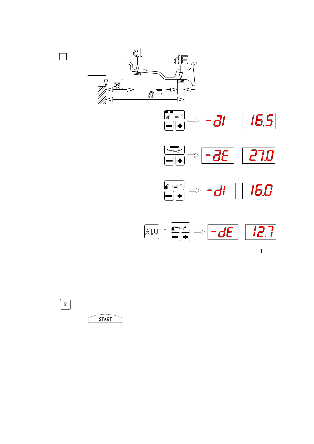
6.1.2 - Wheels with weights inside (alu-s)
Use the automatic distance gauge as follows:
7
ALU-S inside I (aI)
INTERNAL LIMIT, COUNTERWEIGHT
- Move the gauge to the position indicated in g. 7; after successful memorization (g. 6), move the gauge further to
inside the wheel as shown in g. 8.
8
ALU-S outside E (aE)
EXTERNAL LIMIT, COUNTERWEIGHT
- Hold the position for approx. 2 seconds. Successful memorization is indicated by the display as shown in g. 9.
9
- Return the gauge to position 0. The measured distance aI appears on the display together with its value (see g.
11).
- Preset the values for the diameter on the inside and diameter on the outside as described in points c) and d) in
section WHEELS WITH WEIGHTS INSIDE (ALU-S).
Page 9

GB
a
d
b
6.2 - Manual presetting
The dimensions can be entered or modied in manual mode by proceeding as follows:
6.2.1 - Standard wheels
10
Reading
- DISTANCE: preset distance “a” of the wheel inside
from the machine after measuring it with relative gauge.
Increment pitch 0.5 cm
Full scale 40 cm
- DIAMETER: preset nominal diameter “d” marked
on the tyre.
Increment pitches:
- unit of measurement in mm = 12/13 mm
- unit of measurement in inches = 0.5”
- WIDTH: preset the nominal width stamped
on the rim or else measure dimension “b” of
g. 10 with the calliper gauge (standard accessory).
Increment pitches:
- unit of measurement in mm = 5 mm
- unit of measurement in inches = 0.25”
( .2 is displayed for 1/4”; .5 for 1/2”; 7 for 3/4” )
10a
10b
10c
I 0147 - 9
Page 10
I 0147 - 10
I 0147 - 11
GB
GB
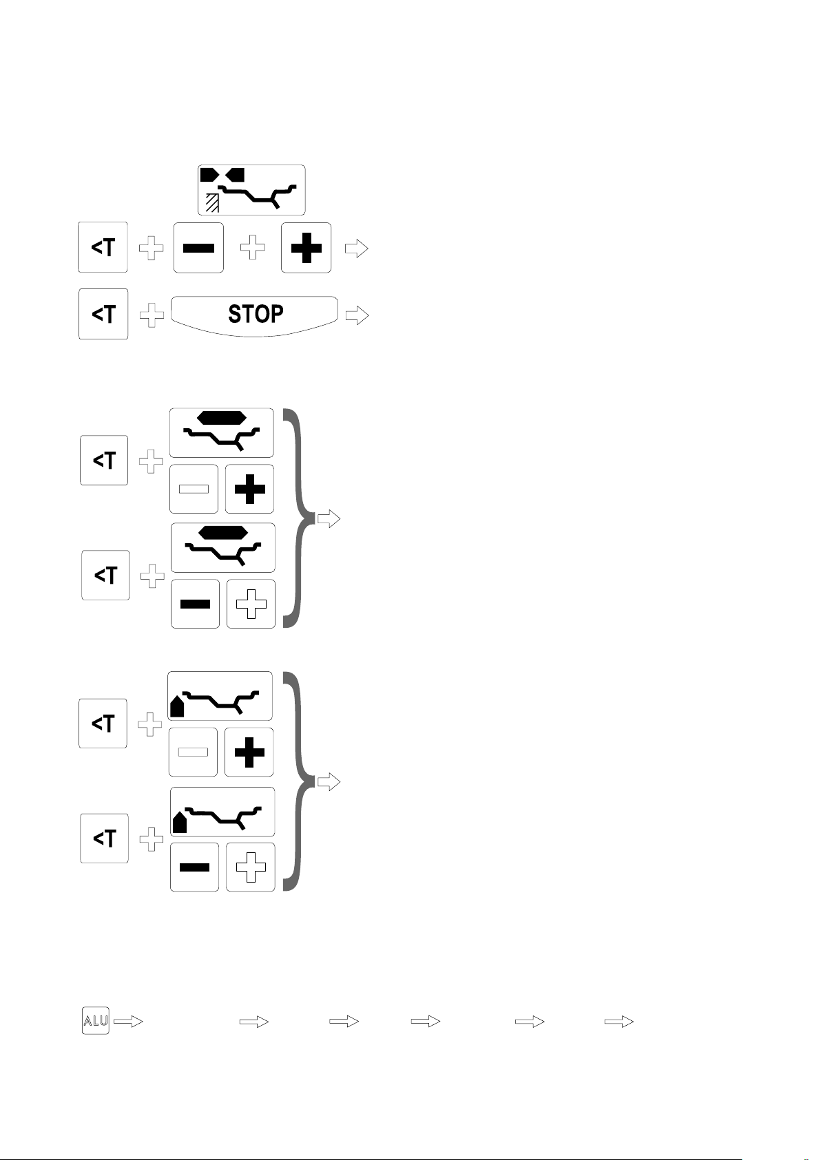
6.2.2 - Wheels with weights inside (alu-s)
Measure the dimensions according to the scheme given below:
11
0 gauge
SEQUENCE:
a) To change aI press
b) To change aE press
14 mm car
20 mm truck
c) To change dI press
d) To change dE press
N.B.: dE by default = 0.8 dI
(keep ALU pressed)
N.B. When dI is reselected, the system automatically sets dE = 0.8 dI.
The system automatically calculates the distance between the centres of gravity of the weights by
considering them approx. 14 mm wide. To display the unbalance regarding the preset dimensions, press
button ; if a spin has already been made, the system automatically recalculates the unbalance;
otherwise press the push button for a new spin.
Page 11

6.3 - Presetting with gauge extension
The extension increases the distance measuring range of the gauge by 10 cm (g. 12).
Proceed as follows:
- Insert the extension on the distance gauge.
- Measure the distance as already described in the above procedures.
- After reading value “a” on the scale, return the gauge to 0 and preset the value “a + 10” in manual mode.
- Preset the diameter and width in manual mode as illustrated in g. 10:
12
reading
extension
6.4 - Double operator program
This program allows memorizes the dimensions of two types of wheels.
Thus two operators can work simultaneously on two different vehicles using the same balancing machine.
The system always memorizes two programs regarding the last two spins carried out with the various preset
dimensions.
When the machine is switched on, the programs are the same.
To change the program, press
Display, Program 1:
DIMENSIONS: as shown in g. 10a/b/c
UNBALANCE: as shown in g. 13-14
Display, Program 2:
DIMENSIONS UNBALANCE
unit of measurement = grams unit
of measurement = ounces
N.B.
- Each time the dimensions are changed and a spin is performed subsequently, the system saves Program 1 in Program 2 while the current dimensions are saved in Program 1. In this way, the programs regarding the last two types
of wheels balanced are always available.
- This mode of operating is also valid for dimensions regarding the special “ALU-S” function.
I 0147 - 11
GB
Page 12
I 0147 - 12
I 0147 - 13
GB
GB
6.5 - Options
SELECTIONS MEMORIZED ALSO WHEN MACHINE IS SWITCHED OFF:
- UNIT of unbalance measurement grams/ounce
- Starting with guard closed (optional)
SELECTIONS LOST WHEN MACHINE IS SWITCHED OFF:
or
or
- UNIT of WIDTH measurement mm/inch
(with “DIMENSIONS PRESETTING” by selecting
WIDTH)
N.B. In inches each time the machine is switched on
- UNIT of DIAMETER measurement mm/inch
(with “DIMENSIONS PRESETTING” by selecting
DIAMETER)
N.B. In inches each time the machine is switched on.
Display of unbalance:
Dinamyc Static Dynamic
Alu S Alu 1 Alu 2
Page 13
7 - Wheel balancing
7.1- Unbalance measurement
- To perform a measuring spin, close the guard ( press if the “Start with guard close” function is not
enabled: see section 6.5).
- In a few seconds, the wheel is brought up to speed and again braked; the unbalance values remain memorized on
instruments 1 and 2.
- The displays with the LED’s lit up indicate the correct angular position where to mount the counterweights (12
o’clock position).
- In this screen a light pressing of button will cause the preset dimensions to appear in sequence:
13
14
CORRECTION ON OUTSIDE
CORRECTION ON INSIDE
: performs the wheel locking/release: useful for xing the unbalance correction weights.
At the end of a measuring spin:
- search for the unbalance position on the outside.
- press to lock the wheel;
- Apply the correction weight shown on the right display;
- press to release the wheel.;
- Proceed in the same way for the inside
7.2 - Recalculation of the unbalance
- Preset the new dimensions following the above described methods.
- Without repeating the spin, press .
The new recalculated unbalance values are displayed.
I 0147 - 13
GB
Page 14

I 0147 - 14
I 0147 - 15
GB
GB
7.3 - Minimization of static unbalance
INTERNAL LIMIT, COUNTERWEIGHT
- When using the normal commercially available weights, with pitch of 5 in every 5 g, there could be a residual static
unbalance of up to 4 g. The damage of such approximation is emphasized by the fact that static unbalance is
cause of most of the disturbances on the vehicle. The computer automatically indicates the optimum entity of the
weights to be applied by approximating them in an “intelligent” way according to their position. (Pitch 5 grams/0.25
ounce for cars, 50 grams/1 ounce for trucks).
- Press to display the actual unbalance (Pitch 1 gram/0.1 ounce).
- The instruments indicate “0” for unbalance less than 5 grams/=.4 for cars and 50 grams/2 ounces for trucks; to
display the residual unbalance press .
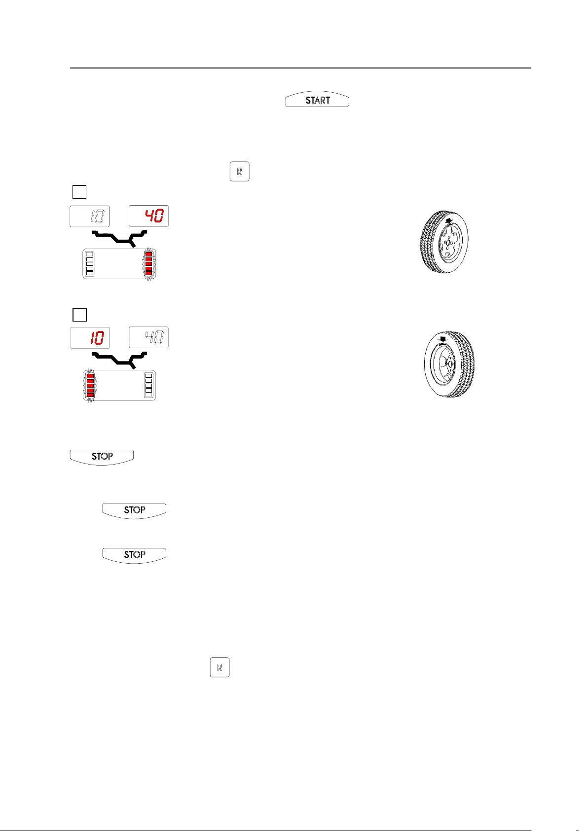
7.4 - Indication of counterweight position in alu-s
After calibrating the machine in ALU-S mode, proceed as follows to cancel approximations made in mounting the
counterweights:
- Press + the following appears:
:
DISTANCE NOT DEFINED
- Extract the distance gauge.
- The reaching of the correction application position for the unbalance correction weights is indicated by the
unbalance display on the relative plane (see g. 15)
15
DISTANCE FOR APPLICATION
OF WEIGHT ON INSIDE
DISTANCE FOR APPLICATION
OF WEIGHT ON OUTSIDE
EXTERNAL LIMIT, COUNTERWEIGHT
Page 15

12/13 mm
7.5 - Static - alu
The available functions allows indicating the correction weights to be placed in the different positions compared to the
normal ones:
- Press to select the required function (see OPTIONS).
- The unbalance values are displayed corrected on the basis of the correction position selected.
16
Standard - Balancing of steel or light alloy rims by applying clip-on weights on
the rim edges.
Static - STATIC correction is required for motor cycle wheels or when it is not
possible to place counterweights on both sides of the rim.
ALU 1 - Balancing of light alloy rims with application of adhesive weights on
the rim shoulders.
Rim resting surface
ALU 2 - Balancing of light alloy rims with hidden application of the outer adhesive weight. The xed position of the external weight is shown in the gure.
N.B. - ALU1 and ALU2 can only be selected for car wheels.
- For correction operation of the ALU functions, mount the wheel to be
balanced on an adapter for car wheels.
- For a quick selection of NORMAL DYNAMIC from any other type of
correction push buttons + .at the same time.
I 0147 - 15
GB
Page 16

I 0147 - 16
I 0147 - 17
GB
GB
8 - Unbalance optimization
) of the unbalance compared to the actual wheel
situation.
- LH display: actual static unbalance which can be
reduced by wheel-rim rotation.
- This function serves to reduce the amount of weight to be added in order to balance the wheel.
- It is suitable for static unbalance exceeding 30 g.
- In many cases it is also possible to improve the residual eccentricity of the tyre.
- The operations described below should be carried out with great care in order to obtain the best results.
Press:
(Press if it is wished to cancel the
function).
- The display prompts the operator to rotate
the rim-tyre. Mark with chalk a reference sign on the
adapter and rim in order to ret the rim in the same position of the machine.
(Use scale on the spindle).
- With the aid of a tyre remover, turn the tyre on the rim
by 180°.
- Ret the rim on the adapter in the previous position.
RH display: possible percentage reduction (symbol
Turn the wheel under the outer LED’s light up:
mark the tyre in the 12 o’clock position.
In the same way, mark the rim corresponding to the
position indicated by the innermost LED’s.
- Make the two points to coincide.
- In this example, an 80% reduction of the static unbalance of 45 grams is achieved with a residual of approx. 9
grams.
8.1 - Visual wheel examination
In certain cases, it is considered appropriate to rotate the wheel with the guard open in order to check the
state of the tread.
- Press and with the other hand press .
- One complete measuring spin is performed. The function is disabled automatically at the end of the cycle.
WARNING! The use of this function is at the operator’s own risk and peril.
Page 17
+
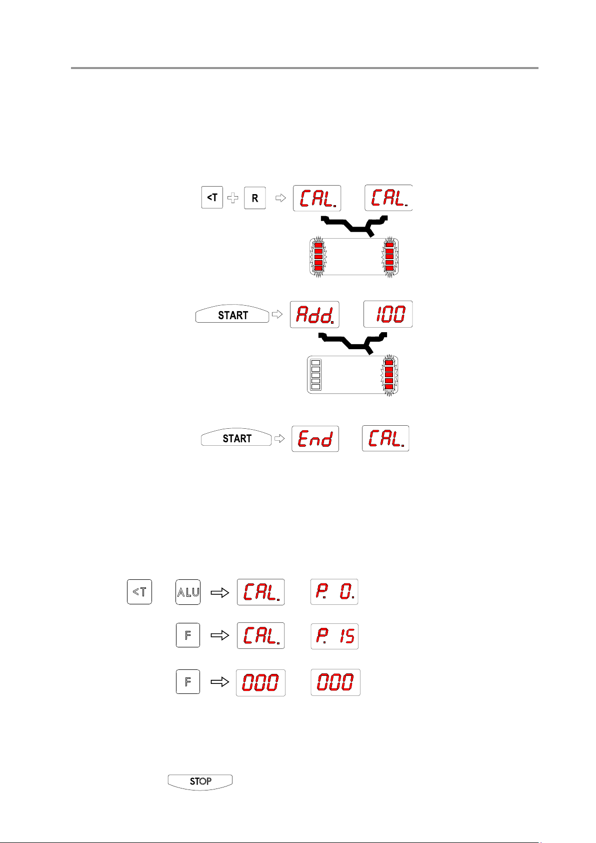
9 - Self-calibration
9.1 - Wheel balancer
For self-calibration of the machine, proceed as follows:
- Fit a medium-sized wheel with steel rim on the shaft. Example: 6" x 14" (± 1")
- Preset the exact dimensions of the wheel mounted.
CAUTION!! Presetting of incorrect dimensions would mean that the machine is not correctly calibrated, therefore
all subsequent measurements will be incorrect until a new self-calibration is performed with the correct
dimensions!
- Hold down keys
- Press
- Press
until the positioning LED’s
change from ashing into
steady.
- It is highly important to
avoid the wheel from
being knocked during
this spin.
- Add a 100 gram weight
(3.5 oz) on the outside in
any angular position.
- MACHINE CALIBRATED
- Remove the reference
weight and balance the
wheel as described previously.
The values derived by the machine from the self-calibration cycle are automatically memorized in a special memory
which retains them even when the machine is switched off. Hence each time the machine is switched on again, it is
ready for correct operation. However, the self-calibration operation can be repeated whenever required or if there is
some doubt as to the correct operation of the machine.
9.2 - Automatic rim distance gauge
Press:
Shift the distance gauge to position “0” and keeping it quite still, press:
Shift the distance gauge to position “15” and keeping it quite still, press:
CORRECT CALIBRATION
- Return the gauge to rest position
- The wheel balancer is ready for operation
N.B. In the event of errors or faulty operation, the writing CAL P.O appears on the display: shift the gauge
to position 0 and repeat the calibration operation exactly as described above. If the error persists, contact
the Technical Service Department. In the event of incorrect input in the rim distance gauge calibration
function, press to cancel it.
I 0147 - 17
GB
Page 18

I 0147 - 18
I 0147 - 19
GB
GB
10 - Errors
Various abnormal conditions can arise during machine operation. When detected by the microprocessor, they appear
on the monitor as:
ERRORS CAUSES CONTROLS
Err. 1 No rotation signal. 1. Verify belt tautness.
Err. 2 Speed too low during detection.
Err. 3 Unbalance too high. 1. Verify wheel dimension settings.
Err. 4 Rotation in opposite direction.
Err. 5 Guard open
Err. 7 /
Err. 8
During unbalance measurement rotation, wheel speed
is less than 42 rpm.
After pressing [START], the wheel begins to rotate in
the opposite direction (anticlockwise).
The [START] pushbutton was pressed without rst
closing the guard.
NOVRAM parameter read error 1. Repeat machine calibration
2. Verify the function of the phase pick-up board and, in particular,
the reset signal.
3. Replace the phase pick-up board.
4. Replace the computer board.
1. Make sure that a vehicle wheel is mounted on the wheel balancer.
2. Verify belt tautness.
3. Verify the function of the phase pick-up board and, in particular,
the reset signal.
4. Replace the computer board.
2. Check detection unit connections.
3. Perform machine calibration.
4. Mount a wheel with more or less known unbalance (less than 100
grammes) and verify the response of the machine.
5. Replace the computer board.
1. Verify the connection of the UP/DOWN – RESET signals on the
phase pick-up board.
1. Reset the error by pressing pushbutton [7]=End.
2. Close the guard.
3. Verify the function of the protection uSwitch.
4. Press the [START] pushbutton.
2. Shut down the machine.
3. Wait for a minimum time of ~ 1 Min.
4. Re-start the machine and verify correct operation.
5. Replace the computer board.
10.1 - Inconsistent unbalance readings
Sometimes after balancing a wheel and removing it from the balancing machine, it is found that,
upon mounting it on the machine again, the wheel is not balanced.
This does not depend on incorrect indication of the machine, but only on faulty mounting of the
wheel on the adapter; i.e. in the two mountings, the wheel has assumed a different position with
respect to the balancing machine shaft centre line.
If the wheel has been mounted on the adapter with screws, it could be possible that the screws have not been correctly tightened, i.e. crosswise one by one, or else (as often occurs) holes have been drilled on the wheel with too wide
tolerances.
Small errors, up to 10 grams (0.4 oz) are to be considered normal in wheels locked by a cone; the
error is normally greater for wheels fastened with screws or studs.
If, after balancing, the wheel is found to be still out-of-balance when retted on the vehicle, this
could be due to the unbalance of the car brake drum or very often due to the holes for the screws on
the rim and drum sometimes drilled with too wide tolerances. In such case a readjustment could be
advisable using the balancing machine with the wheel mounted (For example, see our models L36,
L38/2).
Page 19

11 - Self-diagnostics
When +
are pressed together, a test is enabled for the correct operation of the displays and LED’s of the
PC board after the end of which the wording
appears on the left display. At this point, correct operation of the
position sensor can be checked by looking at the positioning LED’s regarding the outside:
- When the wheel is moved slowly in the direction of rotation of the machine, the AUTO LED should start ashing
while the ALU-S LED should remain steady.
- When the wheel is moved slowly in the opposite direction, the AUTO LED should start ashing while the ALU1 LED
should remain steady.
- When switching from reset, the wording “ ” should appear on the right display..
- Press .
- A number appears on the RIGHT display, which is useful for calibrating the rim distance gauge (only for specialized
personnel).
- Press .
12 - Routine maintenance (see exploded drawings)
Before carrying out any operation, disconnect the machine from the mains.
12.1 - To replace the driving pulley
- Remove the head and the weight shelf being careful not to pull away the electrical cables.
- Unscrew the pulley mounting screw in order to replace the pulley.
- Check supply pressure of the spinner device (see PRESSURE ADJUSTMENT FOR SPIN AND BRAKING DEVICE).
- Excessive pressure will cause premature damage of the rubber.
12.2 - To replace the brake pad
Back-off the two screws fastening the worn brake pad to the motor mounting brake. Securely x the new brake pad
by tightening the screws.
12.3 - To replace the fuses
Remove the weight shelf in order to gain access to the power supply board on which two fuses are installed. If the
fuses need replacement, use ones of the same current rating. If the fault persists, contact the Technical Service Department.
12.4 - Maintenance of the special pneumatic circuit
It is important to periodically clean the compressed air lter and check that there be sufcient lubricating
oil The bowl should be lled 3/4; to top up, use mineral oil of medium viscosity (30 cSt at 20° C) (WAIRSOL, LXOL grade). Normal oil ow rate is one drop every 10 operations.
N.B.: DRAIN FREQUENTLY ANY CONDENSATE BUILT UP IN THE FILTER BOWL VIA RELATIVE
VALVE.
NONE OF THE OTHER MACHINE PARTS REQUIRE MAINTENANCE.
I 0147 - 19
GB
Page 20

13 - Recommended spare parts list (References on the exploded drawings)
CODE DESCRIZIONE
182185730 Balancing spring
07FG33406 Rubber covered driving pulley
42FB37113 Complete brake pad
020620803 Bearing 6208-2Z Ø 40/80/18
67M38954M Position pick-up board c/w cable
182185750 Spring, rim distance gauge 18575P
05PR33399 Display panel
511231002 Switch KL 1002 + Q 555
86PR33822 Complete panel
86SC33821 Computer board
86SC33823 Power board
681002000 Fuses DM 5x20 2A
86SB35583 Cable with DISTANCE potentiometer + board
162368905 Pneumatic control 368-905
SPECIAL PARTS FOR 230V MACHINES
86SZ45288 Complete power board
568001458 Capacitor 14MF 450V Faston vite/screw M8
165000026 Illuminated anti-interference adapter 230V - A05G25
16SP33941 Set of solenoid valves 230V 50/60 Hz
160007221 Coil MB58 230V 50/60 Hz
611000308 Transformer 30VA (230V)
SPECIAL PARTS FOR 115V MACHINES
86SZ45289 Complete power board
568003558 Capacitor 35MF 450V Faston vite/screw M8
165000014 Illuminated anti-interference adapter 115V - A05G24
16SP33942 Set of solenoid valves 115V 50/60 Hz
160007222 Coil MB57 115V 50/60 Hz
611000307 Transformer 30VA (115V)
GB
I 0147 - 20
 Loading...