

Page 1
CTK900-ES-1
Page 2
GUIDELINES LAID DOWN BY FCC RULES FOR USE OF THE UNIT IN THE U.S.A. (not applicable to other areas).
NOTICE
This equipment has been tested and found to comply with the limits for a Class B digital device, pursuant to Part 15 of the
FCC Rules. These limits are designed to provide reasonable protection against harmful interference in a residential
installation. This equipment generates, uses and can radiate radio frequency energy and, if not installed and used in
accordance with the instructions, may cause harmful interference to radio communications. However, there is no guarantee
that interference will not occur in a particular installation. If this equipment does cause harmful interference to radio or
television reception, which can be determined by turning the equipment off and on, the user is encouraged to try to correct
the interference by one or more of the following measures:
• Reorient or relocate the receiving antenna.
• Increase the separation between the equipment and receiver.
• Connect the equipment into an outlet on a circuit different from that to which the receiver is connected.
• Consult the dealer or an experienced radio/TV technician for help.
FCC WARNING
Changes or modifications not expressly approved by the party responsible for compliance could void the user’s authority
to operate the equipment.
Important!
Please note the following important information before using this product.
•
Before using the optional AD-5 Adaptor to power the unit, be sure to check the AC Adaptor
for any damage first. Carefully check the power cord for breakage, cuts, exposed wire and
other serious damage. Never let children use an AC adaptor that is seriously damaged.
• Never attempt to recharge batteries.
• Do not use rechargeable batteries.
• Never mix old batteries with new ones.
• Use recommended batteries or equivalent types.
• Always make sure that positive (+) and negative (–) poles are facing correctly as indicated
near the battery compartment.
• Replace batteries as soon as possible after any sign they are getting weak.
• Do not short-circuit the battery terminals.
• The product is not intended for children under 3 years.
• Use only CASIO AD-5 adaptor.
• The AC adaptor is not a toy.
• Be sure to disconnect the AC adaptor before cleaning the product.
This mark applies in EU countries only.
CASIO Europe GmbH
Bornbarch 10, 22848 Norderstedt, Germany
707A-E-002A
Page 3
Safety Precautions
Safety Precautions
Congratulations on your selection of the CASIO electronic
musical instrument.
• Before using the instrument, be sure to carefully read
through the instructions contained in this manual.
• Please keep all information for future reference.
Symbols
Various symbols are used in this user’s guide and on the
product itself to ensure that the product is used safely and
correctly, and to prevent injury to the user and other persons
as well as damage to property. Those symbols along with
their meanings are shown below.
Alkaline Batteries
Perform the following steps immediately if fluid
leaking from alkaline batteries ever gets into
your eyes.
1. Do not rub your eyes! Rinse them with
water.
2. Contact your physician immediately.
Leaving alkaline battery fluid in your eyes can
lead to loss of sight.
DANGER
This symbol indicates information that, if ignored or applied
incorrectly, creates the danger of death or serious personal
injury.
WARNING
This indication stipulates matters that have the risk of
causing death or serious injury if the product is operated
incorrectly while ignoring this indication.
CAUTION
This indication stipulates matters that have the risk of
causing injury as well as matters for which there is the
likelihood of occurrence of physical damage only if the
product is operated incorrectly while ignoring this
indication.
Symbol Examples
This triangle symbol ( ) means that the user
should be careful. (The example at left indicates
electrical shock caution.)
This circle with a line through it ( ) means that
the indicated action must not be performed.
Indications within or nearby this symbol are
specifically prohibited. (The example at left
indicates that disassembly is prohibited.)
The black dot ( ) means that the indicated
action must be performed. Indications within
this symbol are actions that are specifically
instructed to be performed. (The example at left
indicates that the power plug must be unplugged
from the electrical socket.)
Smoke, Strange Odor, Overheating
Continued use of the product while it is
emitting smoke, a strange odor, or heat creates
the risk of fire and electric shock. Take the
following steps immediately.
1. Turn off power.
2. If you are using the AC adaptor for power,
unplug it from the wall outlet.
3. Contact your original retailer or an
authorized CASIO Service Provider.
AC Adaptor
● Misuse of the AC adaptor creates the risk of
fire and electric shock. Always make sure
you observe the following precautions.
• Be sure to use only the AC adaptor that is
specified for this product.
• Use only a power source whose voltage is
within the rating marked on the AC
adaptor.
• Do not overload electrical outlets and
extension cords.
● Misuse of the AC adaptor’s electric cord can
damage or break it, creating the risk of fire
and electric shock. Always make sure you
observe the following precautions.
• Never place heavy objects on the cord or
subject it to heat.
• Never try to modify the cord or subject it to
excessive bending.
• Never twist or stretch the cord.
• Should the electric cord or plug become
damaged, contact your original retailer or
authorized CASIO Service Provider.
707A-E-003A
E-1
Page 4
Safety Precautions
● Never touch the AC adaptor while your hands
are wet.
Doing so creates the risk of electric shock.
● Use the AC adaptor where it will not be
splashed with water. Water creates the risk of
fire and electric shock.
● Do not place a vase or any other container
filled with liquid on top of the AC adaptor.
Water creates the risk of fire and electric shock.
Batteries
Misuse of batteries can cause them to leak,
resulting in damage to nearby objects, or to
explode, creating the risk of fire and personal
injury. Always make sure you observe the
following precautions.
• Never try to take batteries apart or allow them
to become shorted.
• Never expose batteries to heat or dispose of
them by incineration.
• Never mix old batteries with new ones.
• Never mix batteries of different types.
• Do not charge the batteries.
• Make sure the positive (+) and negative (–)
ends of the batteries are facing correctly.
Do not incinerate the product.
Never throw the product into fire.
Doing so can cause it to explode, creating the risk
of fire and personal injury.
Water and Foreign Matter
Dropping and Impact
Continued use of this product after it has been
damaged by dropping or subjecting it to strong
impact creates the risk of fire and electric shock.
Take the following steps immediately.
1. Turn off power.
2. If you are using the AC adaptor for power,
unplug it from the wall outlet.
3. Contact your original retailer or an
authorized CASIO Service Provider.
Plastic Bags
Never place the plastic bag the product comes in
over your head or in your mouth. Doing so
creates the risk of suffocation.
Particular care concerning this precaution is
required where small children are present.
Keep off of the product and stand.*
Climbing onto the product or stand can cause it
to tip over or become damaged. Particular care
concerning this precaution is required where
small children are present.
Location
Avoid locating the product on an unstable
stand, on an uneven surface, or any other
unstable location. An unstable location can
cause the product to fall over, creating the risk
of personal injury.
Water, other liquids, and foreign matter (such as
pieces of metal) getting into the product create
the risk of fire and electric shock. Take the
following steps immediately.
1. Turn off power.
2. If you are using the AC adaptor for power,
unplug it from the wall outlet.
3. Contact your original retailer or an
authorized CASIO Service Provider.
Disassembly and Modification
Never try to take this product apart or modify it
in any way. Doing so creates the risk of electric
shock, burn injury, or other personal injury.
Leave all internal inspection, adjustment, and
maintenance up to your original retailer or
authorized CASIO Service Provider.
E-2
707A-E-004A
Page 5

Safety Precautions
AC Adaptor
● Misuse of the AC adaptor creates the risk of
fire and electric shock. Always make sure
you observe the following precautions.
• Do not locate the electric cord near a stove
or other sources of heat.
• Never pull on the cord when unplugging
from the electrical outlet. Always grasp
the AC adaptor when unplugging.
● Misuse of the AC adaptor creates the risk of
fire and electric shock. Always make sure
you observe the following precautions.
• Insert the AC adaptor into the wall outlet as
far as it will go.
• Unplug the AC adaptor from the wall
outlet during lightening storms or before
leaving on a trip or other long-term
absence.
• At least once a year, unplug the AC
adaptor from the wall outlet and wipe
away any dust that is built up in the area
around the prongs of the plug.
Relocating the Product
Before relocating the product, always unplug
the AC adaptor from the wall outlet and
disconnect all other cables and connecting cords.
Leaving cords connected creates the risk of
damage to the cords, fire, and electric shock.
Cleaning
Before cleaning the product, always unplug the
AC adaptor from the wall outlet first. Leaving
the AC adaptor plugged in creates the risk of
damage to the AC adaptor, fire, and electric
shock.
Connectors
Connect only the specified devices and
equipment to the product’s connectors.
Connection of a non-specified device or
equipment creates the risk of fire and electric
shock.
Location
Avoid the following locations for this product.
Such locations create the risk of fire and electric
shock.
• Areas subject to high humidity or large
amounts of dust
• In food preparation areas or other areas
subject to oil smoke
• Near air conditioning equipment, on a
heated carpet, in areas exposed to direct
sunlight, inside of a vehicle parked in the
sun, or any other area that subjects the
product to high temperatures
Display Screen
• Never push on the display screen’s LCD panel
or subject it to strong impact. Doing so can
cause the LCD panel’s glass to crack, creating
the risk of personal injury.
• Should the LCD panel ever crack or break,
never touch the liquid inside of the panel.
LCD panel liquid can cause skin irritation.
• Should LCD panel liquid ever get inside your
mouth, immediately wash out your mouth
with water and contact your physician.
• Should LCD panel liquid ever get into your
eyes or onto your skin, rinse with clear water
for at least 15 minutes, and then contact a
physician.
Batteries
Misuse of batteries can cause them to leak
resulting in damage to nearby objects, or to
explode, creating the risk of fire and personal
injury. Always make sure you observe the
following precautions.
• Use only batteries that are specified for use
with this product.
• Remove batteries from the product if you do
not plan to use it for a long time.
707A-E-005A
Sound Volume
Do not listen to music at very loud volumes for
long periods. Particular care concerning this
precaution is required when using headphones.
High volume settings can damage your hearing.
Heavy Objects
Never place heavy object on top of the product.
Doing so can make the product top heavy,
causing the product to tip over or the object to
fall from it, creating the risk of personal injury.
E-3
Page 6
Safety Precautions
Correct Stand* Assembly
An incorrectly assembled stand can tip over,
causing the product to fall and creating the risk
of personal injury.
Make sure you assemble the stand correctly,
following the assembly instructions that come
with it. Make sure you mount the product on the
stand correctly.
* Stand is available as an option.
When using batteries, be sure to replace them or shift to one of
the alternate power sources whenever you notice any of the
following symptoms.
• Dim power indicator
• Instrument does not turn on
• Display that is flickering, dim, or difficult to read
• Abnormally low speaker/headphone volume
• Distortion of sound output
• Occasional interruption of sound when playing at high
volumes
• Sudden power failure when playing at high volumes
• Flickering or dimming of the display when playing at high
volume
• Continued sound output even after you release a key
• A tone that is totally different from the one that is selected
• Abnormal rhythm pattern and demo tune play
• Loss of power, sound distortion, or low volume when playing
from a connected computer or MIDI device
•
E-4
707A-E-006A
Page 7

Introduction
Introduction
Congratulations upon your selection of this CASIO musical instrument. This keyboard provides you with the following features
and functions.
JJJJ 550 Tones Include Rich Advanced Tones
A total of 332 Advanced Tones are programmed with DSP tones to make them richer and more powerful. Advanced tones like
Stereo Piano and Tremolo Electric Piano enhance the Piano and Electric Piano tones to create a totally new sound.
JJJJ 50 Drawbar Organ Tones
In addition to the 550 standards tones, the keyboard also includes 50 realistic drawbar organ tones. Drawbar organ tones can be
controlled using nine digital drawbars. You can also select percussion or key click, and even edit the parameters of preset tone and
save up to 100 original tones in user tone memory.
JJJJ Flash Memory
Built-in Flash memory lets you expand your selection of tones and rhythms by downloading data from the CASIO MUSIC SITE, or
by the CD-ROM that comes bundled with the keyboard. You can also store up to 200 SMF format music files for playback.
JJJJ PIANO SETTING Button
The press of a button optimizes the keyboard setup for piano play.
JJJJ 160 Preset Rhythms + 16 User Rhythms
A selection of 160 rhythms includes accompaniments for everything from rock to pops and jazz.
You can also transfer accompaniment data from your computer and store up to 16 of them as user rhythms in keyboard memory.
JJJJ Auto Accompaniment
Simply play a chord and the corresponding rhythm, bass and chord parts play automatically. One-touch Preset instantly recalls the
most suitable tone and tempo settings to match the rhythm you are using.
JJJJ Big, Information-packed Display
A big built-in display shows chord names, tempo setting, keyboard information, staff notation of notes played, and more for full
support of all your keyboard play. A built-in backlight keeps the display easy to read, even in total darkness.
JJJJ Song Memory
Record up to six parts in memory, along with their tone, volume, pan position, and other parameters for later playback. Realistic
ensemble play can also be created using the Auto Accompaniment function.
JJJJ Synthesizer Mode
Edit built-in sounds to produce your own original creations. Up to 120 of your own sounds can be stored in memory for recall, just
like the built-in tones.
JJJJ General MIDI compatibility
The General MIDI tones of this keyboard let you connect to a personal computer to enjoy “desktop music” capabilities. This
keyboard can be used as a desktop music input device or sound source, and it's just the thing for playback of commercially available
pre-recorded General MIDI music software.
707A-E-007A
E-5
Page 8

Introduction
JJJJ Powerful effects
A collection of powerful effects, such as DSP, reverb, chorus, and more, give you total control over the type of sound you want. You
can even change the parameters of an effect to create your own, original effects. A 4-band equalizer is also included.
JJJJ Mixer
You can specify tone, volume, pan position, and other parameters for each built-in Auto Accompaniment part. You can also control
the same parameters for each channel during MIDI input.
JJJJ Registration Memory
Keyboard setups can be stored in memory for later recall and instant set up whenever you need them. Up to 32 setups (4 setups ×
8 banks) can be stored in registration memory.
JJJJ Data download from your computer
You can use your computer to download data from the CASIO MUSIC SITE.
E-6
707A-E-008A
Page 9

Contents
Safety Precautions......... E-1
Introduction .................... E-5
General Guide................. E-9
Attaching the Score stand ...................E-10
Playing a Demo Tune..........................E-11
Power Supply ............... E-12
Using batteries ....................................E-12
Using the AC Adaptor .........................E-13
Auto Power Off....................................E-13
Turning Off the Keyboard....................E-14
Memory Contents................................E-14
Connections ................. E-15
Applying Effects to
Tones............................. E-23
Effect Blocks....................................... E-23
Selecting a DSP Type ........................ E-23
DSP Button......................................... E-25
Selecting REVERB ............................. E-25
Selecting CHORUS ............................ E-26
Using the Equalizer ............................ E-27
Auto
Accompaniment ...........E-28
About the MODE button ..................... E-28
Selecting a Rhythm ............................ E-29
Playing a Rhythm ............................... E-29
Adjusting the Tempo .......................... E-29
Using Auto Accompaniment ............... E-30
Basic Operations.......... E-16
To play the keyboard...........................E-16
Selecting a Tone .................................E-16
PIANO SETTING Button .....................E-18
Using the Drawbar
Organ Mode .................. E-19
To select a drawbar organ tone ..........E-20
To edit a drawbar organ tone ..............E-20
Parameter Details ...............................E-21
To save an edited drawbar
organ tone ...........................................E-22
Using an Intro Pattern ........................ E-32
Using a Fill-in Pattern ......................... E-32
Using a Rhythm Variation................... E-32
Synchro Starting Accompaniment
with Rhythm Play................................ E-33
Finishing with an Ending Pattern........ E-33
Using One-touch Preset ..................... E-34
Using Auto Harmonize ....................... E-34
Adjusting the Accompaniment
Volume ............................................... E-35
Mixer Function.............. E-36
What you can do with the Mixer ......... E-36
Turning Channels On and Off ............ E-36
Using the Parameter Edit Mode ......... E-37
How Parameters Work ....................... E-38
707A-E-009A
E-7
Page 10

Contents
Synthesizer Mode......... E-40
Synthesizer Mode Functions...............E-40
Creating a User Tone ..........................E-43
Storing a User Tone In Memory ..........E-45
Registration Memory ... E-46
Registration Memory Features ............E-46
To Save a Setup in Registration
Memory ...............................................E-47
To Recall a Setup from Registration
Memory ...............................................E-48
Song Memory Function
Tracks .................................................E-49
Basic Song Memory operations ..........E-50
Using Real-time Recording .................E-50
Mixer Mode Settings ...........................E-51
... E-49
Using the SMF Player... E-71
Playing Back an SMF ......................... E-73
Configuring Other Settings ................. E-73
MIDI................................ E-75
What is MIDI? ..................................... E-75
General MIDI ...................................... E-75
MIDI Settings...................................... E-75
Using the Music Data Management
Software (on the Bundled CD-ROM)
.. E-76
Troubleshooting ........... E-78
Specifications ............... E-80
Care of your
Instrument..................... E-82
Playing Back from Song Memory........E-52
Recording Melody and Chords
with Step Recording ............................E-52
Recording Multiple Tracks...................E-55
Correcting Mistakes While Step
Recording............................................E-57
Editing Memory Contents ....................E-58
Editing a Song.....................................E-59
Keyboard Settings ....... E-61
Using Layer .........................................E-61
Using Split ...........................................E-62
Using Layer and Split Together...........E-63
Transposing the Keyboard..................E-64
Using Touch Response .......................E-64
Tuning the Keyboard...........................E-65
Changing Other Settings.....................E-66
DSP Algorithm List....... E-83
Appendix .........................A-1
Tone List............................................... A-1
Drum Assignment List .......................... A-8
Rhythm List ........................................ A-10
Fingered Chord Chart......................... A-11
Effect List............................................ A-13
MIDI Implementation Chart
E-8
707A-E-010A
Page 11
General Guide
General Guide
*1 *2
707A-E-011A
E-9
Page 12

General Guide
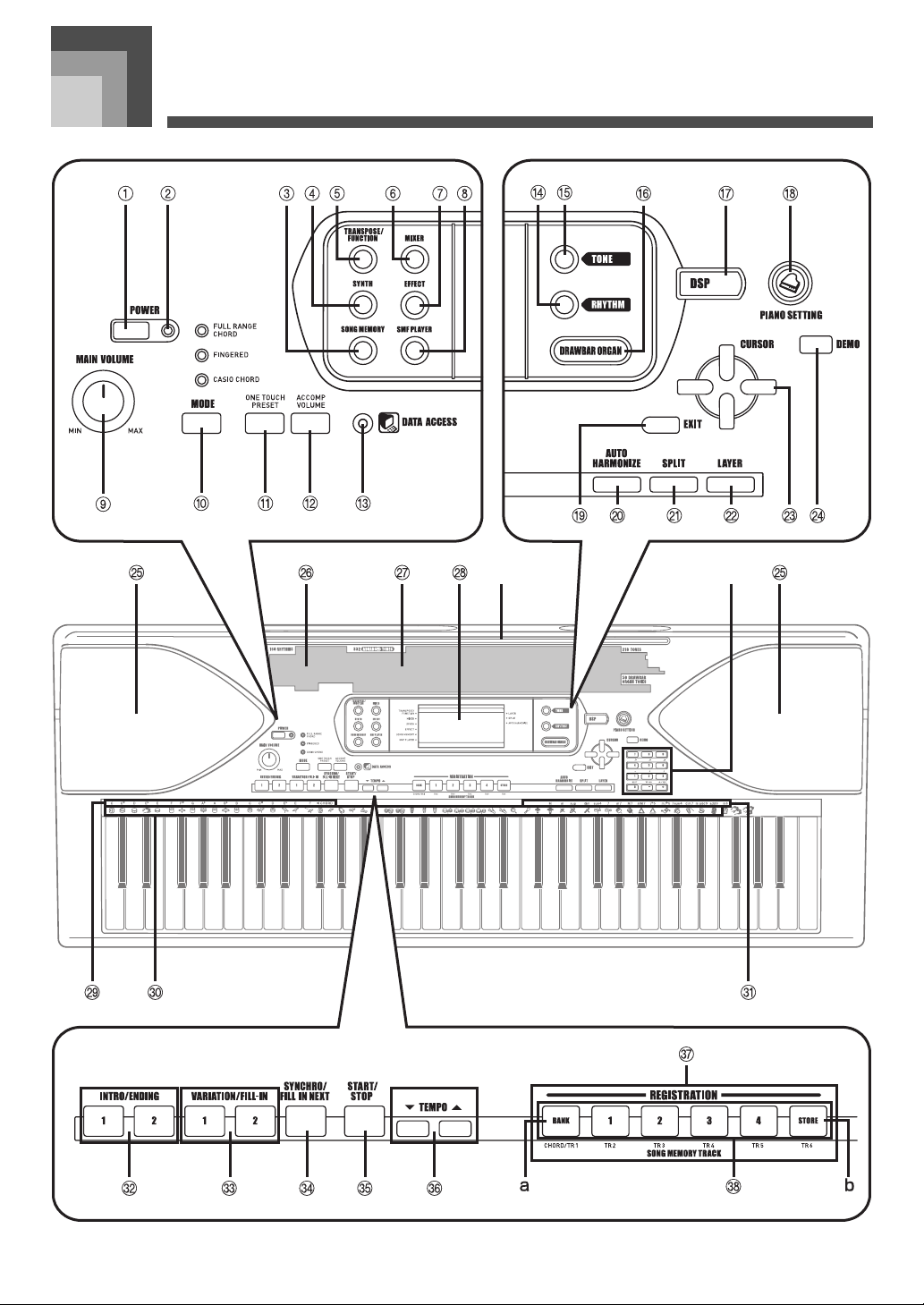
POWER button
1
Power indicator
2
SONG MEMORY button
3
SYNTH button
4
TRANSPOSE/FUNCTION button
5
MIXER button
6
EFFECT button
7
SMF PLAYER button
8
MAIN VOLUME knob
9
MODE button
b
k
ONE TOUCH PRESET button
bl
ACCOMP VOLUME button
b
m
DATA ACCESS indicator
b
n
RHYTHM button
b
o
TONE button
b
p
DRAWBAR ORGAN button
b
q
DSP button
br
PIANO SETTING button
bs
EXIT button
bt
AUTO HARMONIZE button
c
k
SPLIT button
cl
LAYER button
c
m
[ ] / [ ] / [ ] / [ ]CURSOR buttons
c
n
DEMO button (*3)
c
o
Speaker
c
p
Rhythm list
c
q
Tone list
cr
Display
cs
CHORD root names
ct
Percussion instrument list
d
k
Chord types name
dl
INTRO/ENDING 1/2 buttons
d
m
VARIATION/FILL-IN 1/2 buttons
d
n
SYNCHRO/FILL-IN NEXT button
d
o
START/STOP button
d
p
TEMPO buttons
d
q
REGISTRATION buttons
dr
a) BANK button
b) STORE button
SONG MEMORY TRACK buttons
ds
E-10
707A-E-012A
Page 13

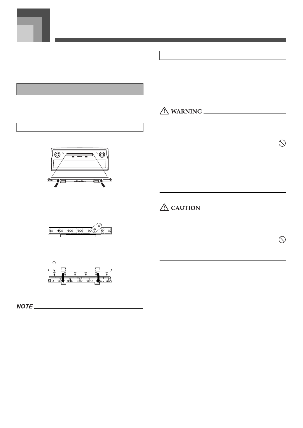
J Attaching the Score stand (*1)
Insert the score stand into the slot at the top of the keyboard as shown in the illustration.
General Guide
707A-E-013A
E-11
Page 14
General Guide
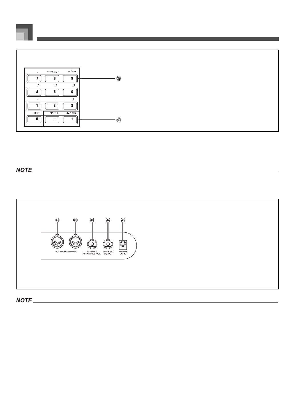
*2
Number buttons
dt
• For input of numbers to change displayed settings.
[+]/[–] buttons (YES/NO)
e
• Negative values can be changed only by using [+] and [–] to
k
increment and decrement the displayed value.
J Playing a Demo Tune (*3)
Pr essing t he DEM O bu tton sta rts de mo tun e play. T here a re 3 de mo t unes , wh ich co ntinuou sly play in s equen ce. To stop d emo tu ne
play, press either the DEMO button or the START/STOP button.
• Pressing the [+]/[–] buttons skips to the next demo tune.
• The PIANO SETTING button, Layer, and Split are disabled while a demo tune is playing.
Rear Panel
MIDI OUT terminal
el
MIDI IN terminal
e
m
SUSTAIN/ASSIGNABLE JACK terminal
e
n
PHONES/OUTPUT terminal
e
o
DC 9V jack
e
p
• Display examples shown in this User’s Guide are intended for illustrative purposes only. The actual text and values that appear on the
display may differ from the examples shown in this User’s Guide.
• Due to LCD element characteristics, display contrast changes depending on the angle from which you view it. The initial default contrast
setting is one that allows easy viewing for a musician seated directly in front of the display. You can also adjust the contrast to the level
that suits your particular needs. For more information, see page E-69.
E-12
Page 15
Power Supply
Power Supply
This keyboard can be powered by current from a standard
household wall outlet (using the specified AC adaptor) or by
batteries. Always make sure you turn the keyboard off
whenever you are not using it.
Using batteries
Always make sure you turn off the keyboard before loading
or replacing batteries.
To load batteries
1. Remove the battery compartment cover.
2. Load six D-size batteries into the battery
compartment.
• Make sure that the positive (+) and negative (–) ends
are facing correctly.
3. Insert the tabs on the battery compartment cover
into the holes provided and close the cover.
Important Battery Information
The following shows the approximate battery life.
• Manganese batteries: Approximately 4 hours
The above value is standard battery life at normal
temperature, with the keyboard volume at a medium
setting. Temperature extremes or playing at very loud
volume settings can shorten battery life.
Misuse of batteries can cause them to leak, resulting in damage
to nearby objects, or to explode, creating the risk of fire and
personal injury. Always make sure you observe the following
precautions.
• Never try to take batteries apart or allow them to
become shorted.
• Never expose batteries to heat or dispose of them by
incineration.
• Never mix old batteries with new ones.
• Never mix batteries of different types.
• Do not charge the batteries.
• Make sure the positive (+) and negative (–) ends of the
batteries are facing correctly.
Misuse of batteries can cause them to leak resulting in damage
to nearby objects, or to explode, creating the risk of fire and
personal injury. Always make sure you observe the following
precautions
• Use only batteries that are specified for use with this
product.
• Remove batteries from the product if you do not plan to
use it for a long time.
Tab
1
• The keyboard may not function correctly if you load or
replace batteries with power turned on. If this happens,
turning the keyboard off and then back on again should
return functions back to normal.
E-12
707A-E-014A
Page 16
Power Supply
1
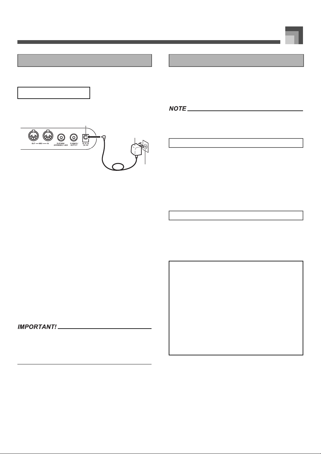
Using the AC Adaptor
Make sure that you use only the AC adaptor specified for this
keyboard.
Specified AC Adaptor: AD-5
Rear Panel
2
3
DC 9V jack
1
AC adaptor AD-5
2
AC outlet
3
Note the following important precautions to avoid damage to
the power cord.
● During Use
• Never pull on the cord with excessive force.
• Never repeatedly pull on the cord.
• Never twist the cord at the base of the plug or
connector.
• The power cord should not be stretched tight
while it is in use.
● During Movement
• Before moving the keyboard, be sure to
unplug the AC adaptor from the power outlet.
● During Storage
• Loop and bundle the power cord, but never
wind it around the AC adaptor.
• Make sure that the keyboard is turned off before connecting
or disconnecting the AC adaptor.
• Using the AC adaptor for a long time can cause it to become
warm to the touch. This is normal and does not indicate
malfunction.
Auto Power Off
When you are using battery power, keyboard power turns off
automatically whenever you leave it on without performing
any operation for about 6 minutes. When this happens, press
the POWER button to turn power back on.
• Auto Power Off is disabled (it does not function) when you
are using the AC adaptor to power the keyboard.
To disable Auto Power Off
Hold down the TONE button while turning on the keyboard
to disable Auto Power Off.
• When Auto Power Off is disabled, the keyboard does not
turn off automatically no matter how long it is left with no
operation being performed.
• Auto Power Off is automatically enabled whenever you
turn on keyboard power.
Settings
Tone, rhythm, and other “main keyboard settings” in effect
when you turn off the keyboard manually by pressing
POWER button or when Auto Power Off turns off power are
still in effect the next time you turn power back on.
Main Keyboard Settings
Tone number, layer, split, split point, drawbar organ
tone settings, transpose, tuning, contrast settings, touch
response, reverb, chorus, DSP, equalizer, rhythm
number, tempo, keyboard channel, MIDI In Chord
Judge on/off, accomp MIDI out on/off, assignable jack
setting, accompaniment volume, user area tones
(Synthesizer Mode), user area accompaniments, user
DSP area, Auto Harmonize on/off, Auto Harmonize
type, Mixer hold, DSP hold, Auto Accompaniment
mode, all Mixer parameters, all Synthesizer Mode
parameters, Song Memory song numbers, SMF player
settings (play mode, manual play part, SMF playback
volume)
707A-E-015A
E-13
Page 17
Power Supply
Turning Off the Keyboard Memory Contents
• Be sure to press the POWER button to turn off power and
make sure that the LCD backlight is off before
disconnecting the AC adaptor or doing anything else.
• Never disconnect the AC adaptor while the keyboard is
turned on or try to turn off power using any other
technique besides pressing the POWER button. Doing so
can cause the contents of the keyboard's Flash memory to
become corrupted. Strange keyboard operation and
abnormal startup when power is turned on are symptoms
of corrupted Flash memory contents. See
“Troubleshooting” on page E-78 for more information.
• While the following message is on the display, never turn off
the keyboard by pressing the POWER button, disconnecting
the AC adaptor, etc.
(message)“Pls Wait” or “Bulk In”
Turning off the keyboard while the above message is on the
display can cause user data (user tones, song memory data,
etc.) currently stored in keyboard memory to become
corrupted. Once corrupted, you may not be able to recall the
data again.
In addition to the above settings, data stored in the
Registration Mode and Song Memory Mode is also retained
when keyboard power is turned off.
Saving Setups and Memory Contents
J About Flash memory
Your keyboard comes with built-in Flash memory, which can
continue to hold data even when electrical power is totally cut
off. This means that even after batteries go completely dead,
you can attach the AC adaptor, turn on power, and still recall
data stored in memory.
• When running under battery power, be sure to replace
batteries as soon as possible after the first signs of low
battery power (dim power indicator lamp, dim display
characters, etc.) Though the keyboard’s Flash memory is
non-volatile (which means that data is not lost when power is
interrupted), data can be lost if power suddenly fails while
data is being written to flash memory*.
* While storing or deleting user data, while recording with
the synthesizer, while transferring data from a computer,
etc.
J Backing Up Data to a Computer
You can use a MIDI connection to back up keyboard settings
and memory contents on a computer’s hard disk. See
“MIDI”on page E-75 for more information.
E-14
Initializing the Keyboard
Initialization can be used to return keyboard parameters to
their initial factory default settings, or to delete all data
currently in keyboard memory. See page E-70 for more
information about initialization.
Returning the keyboard to its initial factory defaults
You can use the CD-ROM that comes with the keyboard and
your computer to return the keyboard’s flash memory and all
of its parameters to their initial factory default settings. See
“Bundled CD-ROM Data” on page E-76 for details.
707A-E-016A
Page 18
Connections
1
Connections
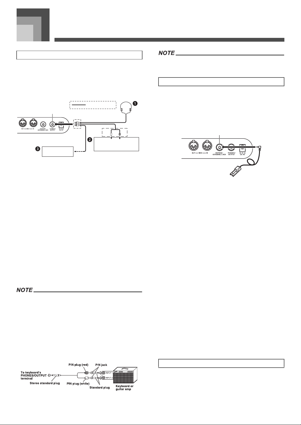
Phones/Output Terminal
Before connecting phones or other external equipment, be
sure to first turn down the volume settings of the keyboard
and the connected equipment. You can then adjust volume to
the desired level after connections are complete.
Rear Panel
Audio connection
PHONES/OUTPUT jack
Stereo standard plug
• You can also connect the keyboard to a computer or
sequencer. See “MIDI” on page E-75 for details.
Sustain/Assignable jack Terminal
You can connect an optional sustain pedal (SP-3 or SP-20) to
the SUSTAIN/ASSIGNABLE JACK terminal to enable the
capabilities described below.
For details on how to select the pedal function you want, see
“Changing Other Settings” on page E-66.
Keyboard amp,
guitar amp, etc.
White
AUX IN or similar terminal
of audio amplifier
LEFT
RIGHT
Red
PIN plug
J Connecting Phones 1
Connecting phones cuts off output from the keyboard’s builtin speakers, so you can play even late at night without
disturbing anyone.
J Audio Equipment 2
Connect the keyboard to a audio equipment using a
commercially available connecting cord with a standard plug
on one end and two PIN plugs on the other end. Note that the
standard plug you connect to the keyboard must be a stereo
plug, otherwise you will be able to output only one of stereo
channels. In this configuration, you normally set the input
selector of the audio equipment to the terminal (usually
marked AUX IN or something similar) where the cord from
the keyboard is connected. See the user documentation that
comes with your audio equipment for full details.
J Musical Instrument Amplifier 3
Use a commercially available connecting cord to connect the
keyboard to a musical instrument amplifier.
• Be sure to use a connecting cord that has a stereo standard
plug on the end you connect to the keyboard, and a
connector that provides dual channel (left and right) input to
the amplifier to which you are connecting. The wrong type of
connector at either end can cause one of the stereo channels
to be lost.
• When connected to a musical instrument amplifier, set the
volume of the keyboard to a relatively low level and make
output volume adjustments using the amplifier’s controls.
Connection Example
SP-20
SUSTAIN/ASSIGNABLE JACK Terminal
1
J Sustain Pedal
• With piano tones, depressing the pedal causes notes to
linger, much like a piano’s damper pedal.
• With organ tones, depressing the pedal causes notes to
continue to sound until the pedal is released.
J Sostenuto Pedal
• As with the sustain pedal function described above,
depressing the sostenuto pedal causes notes to be
sustained.
• This difference between a sostenuto pedal and sustain
pedal is the timing.
• With a sostenuto pedal, you press the keys and then
depress the pedal before you release the keys. Only the
notes that are sounding when the pedal is depressed are
sustained.
J Soft Pedal
Depressing the pedal softens the sound of the notes being
played.
J Rhythm Start/Stop Pedal
In this case, the pedal performs the same functions as the
START/STOP button.
Accessories and Options
Use only the accessories and options specified for this
keyboard. Use of non-authorized items creates the danger of
fire, electrical shock, and personal injury.
707A-E-017A
E-15
Page 19

Basic Operations
Basic Operations
1 2
6
MAIN VOLUME
1
DSP
4
Number buttons
7
This section provides information on performing basic
keyboard operations.
POWER
2
PIANO SETTING
5
[+]/[–]
8
To play the keyboard
1. Press the POWER button to turn the keyboard on.
• This causes the power indicator to light.
2. Use the MAIN VOLUME knob to set the volume to
a relatively low level.
3. Play something on the keyboard.
43 5
7
8
TONE
3
START/STOP
6
Selecting a Tone
This keyboard comes with tones built-in, as shown below.
A partial list of the available tone names is printed on the
keyboard console. See the “Tone List” on page A-1 of this
manual for a complete list.
“Advanced Tones” are variations of standard tones, which
are created by programming in effects (DSP) and other
settings.
For details about drawbar organ tones, see “Using the
Drawbar Organ Mode” on page E-19.
Tone Types
E-16
Standard Tones: 550 Preset Tones + 124 User Tones
Number
000-331 332 Advanced Tones On
400-599 200 Preset Tones Off
600-617 18 Drum Sets Off
700-799 100 User Tones (*2) On/Off (*3)
800-819 20
900-903 4
Number of
Tones
Tone Type
User Tones with Waves
(*4)
User Drum Sets with
Waves (*4)
DSP Line On/Off
(*1)
On/Off (*3)
On/Off (*5)
707A-E-018A
Page 20
Basic Operations
Drawbar Organ Tones:
50 Preset Tones + 100 User Tones
Number
000-049 50 Preset Tones On/Off (*5)
100-199 100 User Tones (*6) On/Off (*3)
*1 See “Changing Tones and Configuring DSP Effect
Settings” on page E-18.
*2 Memory area for tones created by you. See “Synthesizer
Mode” on page E-40. User tone areas 700 through 799
initially contain the same data as DSP types 000 through
099.
*3 Depends on source tone or user setting. See “Synthesizer
Mode” on page E-40 for more information.
*4 Area for data transferred from a computer. See “Using the
Music Data Management Software (on the Bundled CDROM)” on page E-76 for more information. For
information about waveforms, see “Creating a User Tone”
on page E-43.
*5 Depends on tone. This status can be checked by viewing
the DSP button. See “DSP Button” on page E-25 for more
information.
*6 Memory area for tones created by you. See “To edit a
drawbar organ tone” on page E-20. User drawbar organ
tone areas initially contain two sets of the same data as
drawbar organ tones types 000 through 049.
Number of
Tones
Tone Type
DSP Line On/Off
(*1)
To select a tone
1. Find the tone you want to use in the tone list and
note its tone number.
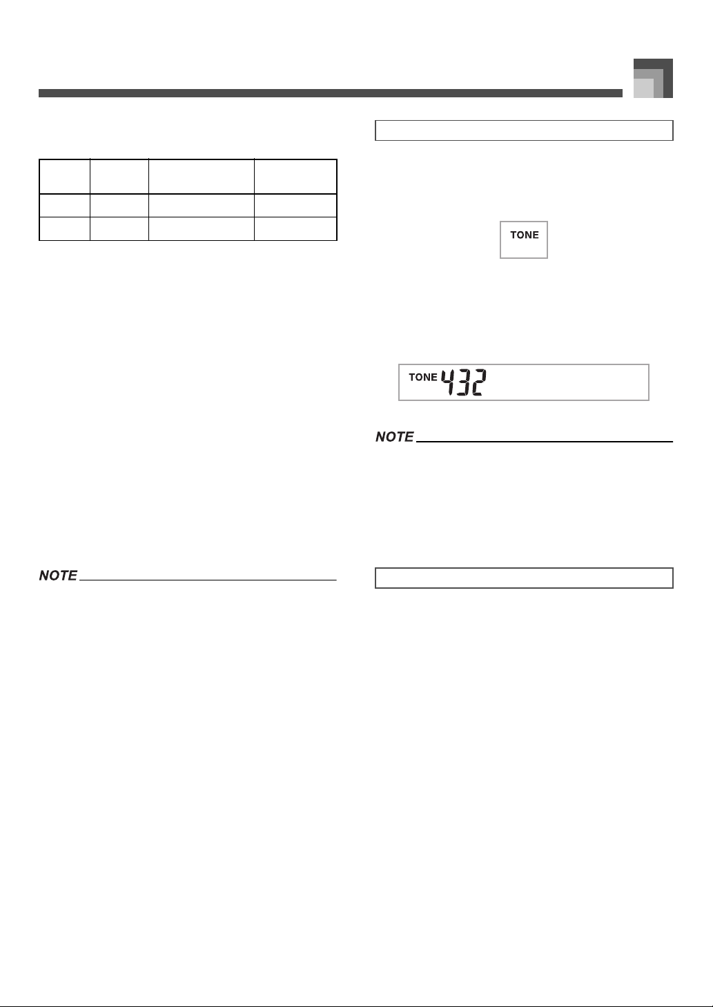
2. Press the TONE button.
3. Use the number buttons to input the three digit
tone number for the tone you want to select.
Example:
To select “432 GM ACOUSTIC BASS”, input 4, 3
and then 2.
AuBsGsoc
• Always input all three digits for the tone number, including
leading zeros (if any).
• You can also increment the displayed tone number by
pressing [+] and decrement it by pressing [–].
• When one of the drum sets is selected (tone numbers 600
through 617), each keyboard key is assigned a different
percussion sound. See page A-8 for details.
• You cannot select tone numbers not included in the above
ranges (standard tones 332 through 399, 618 through 699
and 820 through 899, and drawbar organ tones from 050 to
099). When you use the [+] and [–] buttons to scroll through
tone numbers, scrolling jumps across the unused numbers.
Pressing [+] when 617 is selected, for example, jumps to
700.
707A-E-019A
Polyphony
The term polyphony refers to the maximum number of notes
you can play at the same time. The keyboard has 32-note
polyphony, which includes the notes you play as well as the
rhythms and auto-accompaniment patterns that are played
by the keyboard. This means that when a rhythm or autoaccompaniment pattern is being played by the keyboard, the
number of notes (polyphony) available for keyboard play is
reduced. Also note that some of the tones offer only 10-note
polyphony.
E-17
Page 21
Basic Operations
Changing Tones and Configuring DSP
Effect Settings
This keyboard has only a single DSP sound source. Because of
this, selecting tones for which DSP is enabled for multiple
parts when layering or splitting tones (page E-61, E-62) can
cause conflicts. To avoid conflicts, DSP is allocated to the last
DSP enabled tone, and DSP is disabled (DSP line OFF) for all
other parts.
DSP line is a parameter that controls whether or not the
currently selected DSP effect is applied to a part.* Each tone
has a DSP line parameter. Selecting a tone for a part applies
the tone’s DSP line parameter setting to all parts.
* The DSP line parameter is turned on (DSP effect is applied)
for the 332 Advanced Tones numbered 000 through 331,
and turned off (DSP effect not applied) for the 200 preset
tones from 400 to 599. For information about other tones,
see “Tone Types” on page E-16.
PIANO SETTING Button
Pressing this button changes the setup of the keyboard to
optimize it for piano play.
Settings
Tone number: “000”
Rhythm number: “140”
Accompaniment Mode: Normal
Layer: Off
Split: Off
Auto Harmonize: Off
Transpose: 0
Touch Response: Off: Returns to initial default
On: No change
Assignable Jack: SUS
Local Control: On
Mixer Channel 1 Parameter
Setup:
Depends on tone
• Pressing the PIANO SETTING button while a rhythm is
playing stops rhythm play and then changes the keyboard
setup.
• Pressing the PIANO SETTING button while the keyboard is
in the Synthesizer Mode or other mode exits the current
mode and then changes the keyboard setup.
• The setup of the keyboard does not change if you press the
PIANO SETTING button when any one of the following
exists.
* During real-time recording, step recording, or while using
the editing function of the Song Memory
* While the data save or overwrite message is on the
display
* During demo tune play
J To optimize keyboard settings for piano play
1. Press the PIANO SETTING button.
2. Now try playing something on the keyboard.
• The notes you play will sound with a piano tone.
3. If you want to play with rhythm accompaniment,
press the START/STOP button
• This causes a rhythm that is optimized for piano will
start to play.
• To stop rhythm play, press the START/STOP button
again.
E-18
.
707A-E-020A
Page 22
Using the Drawbar Organ Mode
Using the Drawbar Organ Mode
21
4
5
3
DRAWBAR ORGAN
1
Number buttons
4
Your keyboard has built-in “drawbar organ tones” that can be altered using nine digital drawbars whose operations are similar to
the controls on a drawbar organ. You can also select percussion or key click. There is room in memory for storage of up to 100 usercreated drawbar tone variations.
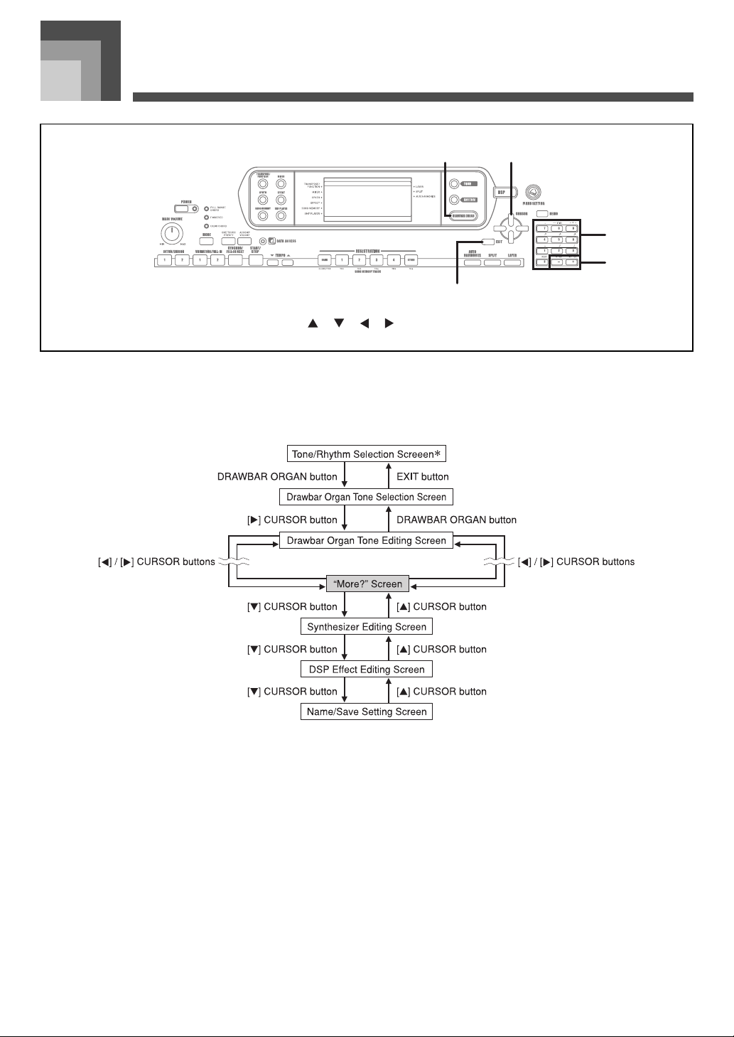
Drawbar Organ Mode Operational Flow
[ ]/[ ]/[ ]/[ ] CURSOR
2
[+]/[–]
5
EXIT
3
* You can also display the drawbar organ tone selection screen from the Song Memory Mode or SMF Playback Mode screen. In
this case, however, the Drawbar Organ Tone Editing Screen does not appear.
707A-E-021A
E-19
Page 23

Using the Drawbar Organ Mode
1 2
1 2
To select a drawbar organ tone
1. Find the drawbar organ tone you want to use in the
tone list and note its tone number.
2. Press the DRAWBAR ORGAN button.
• This causes the drawbar organ tone selection screen to
appear.
Dwar1bar
• While the “More?” screen is on the display, you can
advance to the synthesizer and DSP effect editing
screens by pressing the [ ] CURSOR button or the
[+] button.
3. Use the [ ] and [ ] CURSOR buttons or the [
and [–] buttons to change the setting of the
currently displayed parameter.
• You can also change a parameter setting by entering a
value with the number buttons.
• You can monitor the changes in a tone by playing
notes on the keyboard as you adjust parameter
settings.
+
]
Tone Number
1
Tone Name
2
3. Use the number buttons to input the three digit
tone number for the tone you want to select.
• Always input all three digits for the tone number, including
leading zeros (if any).
• You can also increment the displayed tone number by
pressing [+] and decrement it by pressing [–].
To edit a drawbar organ tone
1. Select the drawbar organ tone (000 to 049, 100 to
199) you want to edit.
2.
Use the [ ] and [ ] CURSOR buttons to display
the drawbar organ tone editing screen. Select the
parameter whose setting you want to change
Example:
Selecting the “Ft16’” parameter
.
F6’1t
• Selecting a different tone after you edit parameters replaces
parameter settings with those of the newly selected tone.
• If you have drawbar organ tones assigned to more than one
channel, changing the drawbar organ tone setting for one of
the channels causes the same setting to be applied to all of
the other channels as well.
• See “To save an edited drawbar organ tone” on page E-22
for information about saving your edits.
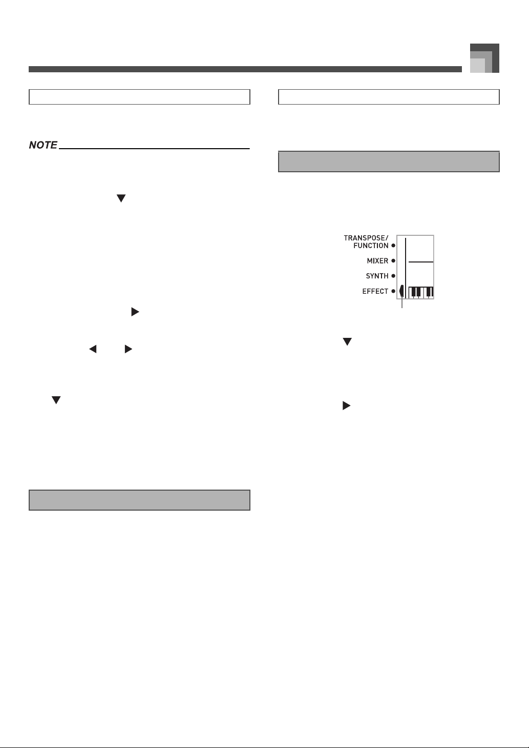
Editing Synthesizer Mode Parameters and
DSP Parameters of Drawbar Organ Tones
As with standard (non-drawbar) tones, you can edit the
Synthesizer Mode parameters and DSP parameters of
drawbar organ tones (See “Drawbar Organ Mode
Operational Flow” on page E-19).
1. Use the [ ] and [ ] CURSOR buttons to display
“More?”, and then press the [ ] CURSOR button.
• This enters the Synthesizer Mode, which is indicated
by the pointer next to SYNTH on the display screen.
• For the remainder of this procedure, perform the steps
starting from step 3 under “Creating a User Tone” on
page E-43.
Parameter Setting
1
Parameter Name
2
• There are a total of 13 parameters. You can use the
[ ] and [ ] CURSOR buttons to cycle through
them. See “Parameter Details” on page E-21 for more
information.
E-20
707A-E-022A
Page 24
Using the Drawbar Organ Mode
Parameter Details
The following provides details about the parameters you can
configure using the drawbar organ tone editing screen.
Drawbar Position
This parameter defines the position of each drawbar, and the
volume of each overtone. The larger the value, the greater the
corresponding overtone’s volume.
Parameter Name
Drawbar 16’ Ft16’ 0 to 3
Drawbar 5 1/3’ Ft 5 1/3’ 0 to 3
Drawbar 8’ Ft 8’ 0 to 3
Drawbar 4’ Ft 4’ 0 to 3
Drawbar 2 2/3’ Ft 2 2/3’ 0 to 3
Drawbar 2’ Ft 2’ 0 to 3
Drawbar 1 3/5’ Ft 1 3/5’ 0 to 3
Drawbar 1 1/3’ Ft 1 1/3’ 0 to 3
Drawbar 1’ Ft 1’ 0 to 3
(Ft: Feet)
Click
The parameter determines whether or not a key click is added
when a sustained tone configured using the drawbars is
played.
Parameter Name
Click Click
Percussion
This parameter lets you add percussion sound, which
provides modulation to sustained tones that you create.
When you hold down a key on the keyboard, the sound
produced decays until it is no longer audible. Pressing the key
again sounds the note again at a louder volume. Percussion
has “2nd Percussion” (2nd overtone pitch) and “3rd
Percussion” (3rd overtone pitch) settings, each of which can
be turned on or off.
You can also specify the percussion decay time, which
controls how long it takes for the percussion sound to decay.
Parameter Display
Indication
Parameter Display
Indication
oFF:
on:
Settings
Settings
Click Off
Click On
Parameter Name
2nd Percussion Second
3rd Percussion Third
Percussion Decay Time Decay 000 to 127
Parameter Display
Indication
Settings
oFF:
on:
oFF:
on:
Off
On
Off
On
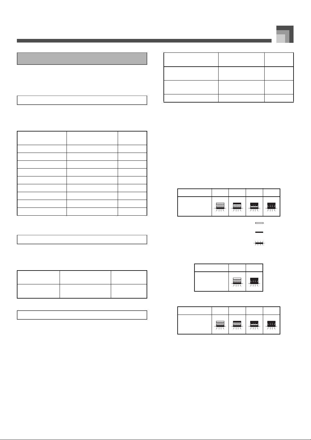
J Display Contents in the Drawbar Organ Mode
In the Drawbar Organ Mode, the current status of the
drawbar positions, key click, and percussion parameters are
indicated on the display’s bar graph as shown in the
illustrations below. There is one line for each parameter, and
the bottom segment of the selected parameter line flashes.
The bottom segment of the bar graph column that represents
the currently selected parameter flashes to indicate that it is
selected.
None of the channel numbers (1 to 16) are displayed in the
drawbar organ tone selection mode and editing mode.
Drawbar Position Graph
Setting Value 0 1 2 3
Display
Off
On
Flash
Click and Percussion On/Off Graph
Setting Value Off On
Display
Percussion Decay Time Graph
Setting Value 0-31 32-63 64-95 96-127
Display
707A-E-023A
E-21
Page 25

Using the Drawbar Organ Mode
To save an edited drawbar
organ tone
1. After editing parameters, use the [ ] and [ ]
CURSOR buttons to display “More?”.
2. Press the [ ] CURSOR button three times to
display the screen for inputting a tone name and
assigning a tone number.
3. Use the [
• You can select a tone number in the range of 100 to 199.
+
] and [–] buttons to select a tone number.
4. After the tone name is the way you want, press the
[ ] CURSOR button to store the tone.
•Use the [+] and [–] buttons to scroll through letters at
the current cursor location.
• Use the [ ] and [ ] CURSOR buttons to move the
cursor left and right.
• See the page E-45 for information about inputting text.
5. After everything is the way you want, press the
[ ] CURSOR button to store the tone.
• This will display a confirmation message asking
whether you really want to save the data. Press the
YES button to save the data.
• After the save operation is complete, the message
“Complete” appears and then the display returns to
the tone selection screen.
• To cancel save, press the EXIT button.
E-22
707A-E-024A
Page 26
Applying Effects to Tones
Applying Effects to Tones
1
EFFECT
1
[ ]/[ ]/[ ]/[ ] CURSOR
4
This keyboard provides you with a selection of effects that
you can apply to tones.
The built-in effects include a wide variety of variations that
give you access to a selection of general digital effects.
EXIT
2
Number buttons
5
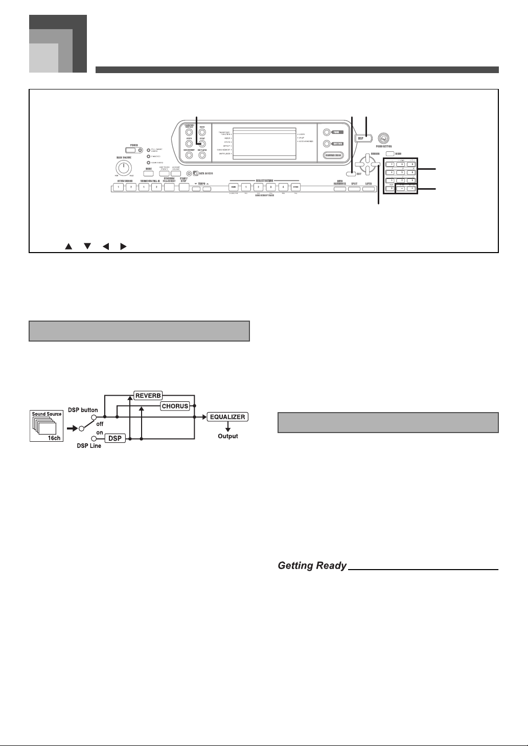
Effect Blocks
The following shows how the effects of this keyboard are
organized.
2 3
5
6
4
DSP
3
[+]/[–]
6
J CHORUS
The chorus effect gives sound greater depth by causing it to
vibrate. You can choose from among 16 different chorus
effects, including “Chorus” and “Flanger.”
The equalizer is another type of effect that you can use to
make adjustments in tone quality. Frequencies are divided
among a number of bands, and raising and lowering the level
of each frequency band alters the sound.
You can reproduce the optimal acoustics for the type of music
you are playing (classics, for example) by selecting the
applicable equalizer setting.
J DSP
DSP effects are applied to the connection between the sound
source and output. You can select distortion and modulation
effects. You can create DSP effect setups and also transfer
downloaded DSP data from your computer. The keyboard
has memory that lets you store up to 100 DSP effect setups.
See “Using the Music Data Management Software (on the
Bundled CD-ROM)” on page E-76 and “Saving the Settings of
DSP Parameters” on page E-25 for more information.
J REVERB
Reverb simulates the acoustics of specific types of
environments. You can choose from among 16 different
reverb effects, including “Room” and “Hall.”
707A-E-025A
Selecting a DSP Type
In addition to the 100 built-in effect types, you can also edit
effect types to create your own and store them in user
memory. You can have up to 100 effect types in user memory
at one time. You can also select the DSP type of the last DSP
enabled tone that you used. This means you always have
access to the DSP type of Advanced Tones and tones you
download over the Internet. To select the DSP type of the last
DSP enabled tone that you used, select “ton” in step 3 of the
procedure below.
Perform the following steps to select a DSP type.
• When using a DSP effect, you should use the Mixer to
confirm that the DSP lines of the required parts are turned
on. See “Mixer Function” on page E-36 for more information.
1. Press the EFFECT button so the pointer appears
next to EFFECT on the display.
• The DSP type setting screen (step 3) will appear
automatically about fives seconds after you press the
button.
E-23
Page 27

Applying Effects to Tones
2. Press the [ ] CURSOR button.
3. Use the [+] and [–] buttons or the number buttons
to select the type of DSP you want.
• See the “Effect List” on page A-13 for information
about the DSP types that can be selected.
• Here you could also change the parameters of the
effect you selected, if you want. See “Changing the
Settings of DSP Parameters” for more information.
• The DSP type display area shows the DSP number (000 to
199) or “ton” (user tone created using DSP).
Changing the Settings of DSP Parameters
You can control the relative strength of a DSP and how it is
applied. See the following section titled “DSP Parameters” for
more information.
1. After selecting the DSP type you want, use the
[ ] and [ ] CURSOR buttons to display the
parameter whose setting you want to change.
• This displays the parameter setting screen.
2. Use the [
+
] and [–] buttons or the number buttons
to make the parameter setting you want.
•Pressing the [+] and [–] buttons at the same time
returns the parameter to its recommended setting.
3. Press the EFFECT or EXIT button.
• This exits the tone or ryhthm setting screen.
z DSP Reverb Send (Range: 000 to 127)
Specifies how much of the post-DSP sound should be sent
to reverb.
z DSP Chorus Send (Range: 000 to 127)
Specifies how much of the post-DSP sound should be sent
to chorus.
• Whether or not an effect is applied to the parts that are
sounding also depends on Mixer Mode Reverb Send,
Chorus Send, and DSP on/off settings. See “Mixer Function”
on page E-36 for more information.
• Playing a demo tune (page E-11) automatically changes the
effect to the one that is assigned to the tune. You cannot
change or cancel a demo tune effect.
• Changing the effect setting while sound is being output by
the keyboard causes a slight break in the sound when the
effect changes.
• A number of tones, called “Advanced Tones,” automatically
turn on the DSP line for richer, higher quality sound. If you
assign an Advanced Tone to a keyboard part (Channels 1
through 4), the DSP line turns on automatically and the DSP
selection changes in accordance with the settings of the
Advanced Tone. Also, the Mixer Mode DSP line on/off
setting for the keyboard part to which the Advanced Tone is
assigned is turned on.*
* The Mixer DSP line setting is automatically turned off for
each part that does not have an Advanced Tone assigned.
Because of this, DSP effects previously applied to these
parts are cancelled, which can make their tone sound
different. In this case, display the Mixer screen and turn
DSP back on.
DSP Parameters
The following describes the parameters for each DSP.
J DSP
z Parameter 0 to 7
These parameters differ in accordance with the
algorithm* of the selected DSP type. See the “Effect List”
on page A-13 and the “DSP Algorithm List” on page E-83
for more information.
* Effector structure and operation type
E-24
707A-E-026A
Page 28
Applying Effects to Tones
1
Saving the Settings of DSP Parameters
You can save up to 100 modified DSPs in the user area for
later recall when you need them.
• User DSP areas 100 through 199 initially contain the same
data as DSP types 000 through 099.
1. After making the DSP parameter settings you
want, press the [ ] CURSOR button.
• This causes the DSP number of the user area where the
DSP will be saved to flash on the display.
2. Use the [
area number where you want to save the new
DSP.
• You can select a user DSP area number in the range of
+
] and [–] buttons to select the user DSP
100 to 199 only.
3. After the user DSP area number you want is
selected, press the [ ] CURSOR button.
•Use the [+] and [–] buttons to scroll through letters at
the current cursor location.
• Use the [ ] and [ ] CURSOR buttons to move the
cursor left and right.
• See the page E-45 for information about inputting text.
4. After everything is the way you want, press the
[ ] CURSOR button to store the effect.
• This will display a confirmation message asking
whether you really want to save the data. Press the
YES button to save the data.
• The message “Complete” appears momentarily on the
display, followed by the tone or rhythm selection
screen.
DSP Button
Checking the DSP button will tell you whether or not DSP is
enabled for the tone that is currently selected for a part. The
DSP button will be lit for a tone that is DSP enabled (DSP line
ON), and unlit for a tone that is D SP disabled (DSP line OFF).
For example, when you move each part while using the split/
layer function, the DSP button lights or goes out in
accordance with that parts setting.
Pressing the DSP button toggles the tone of the part you are
currently playing on the keyboard between enabled (DSP line
ON) and disabled (DSP line OFF).
To turn DSP line on and off
1. Press the DSP button to toggle DSP line for the
currently selected part on and off.
Selecting REVERB
Perform the following steps to select REVERB.
1. Press the EFFECT button, so the pointer appears
next to EFFECT on the display screen.
Pointer
1
2. Press the [ ] CURSOR button once.
• This displays the reverb editing screen.
• The reverb type setting screen (step 4) will appear
automatically about fives seconds after you press the
button.
3. Press the [ ] CURSOR button.
4. Use the [
to scroll through the reverb types until the one you
want is displayed, or use the number buttons to
input the reverb number you want to select.
• See the list on page A-13 for information about the
• Here you could also change the parameters of the
+
] and [–] buttons or the number buttons
types of REVERB effects that are available.
effect you selected, if you want. See “Changing the
Settings of REVERB Parameters” on page E-26 for
more information.
707A-E-027A
E-25
Page 29
Applying Effects to Tones
Changing the Settings of REVERB
Parameters
You can control the relative strength of a reverb and how it is
applied. See the following section titled “REVERB
Parameters” for more information.
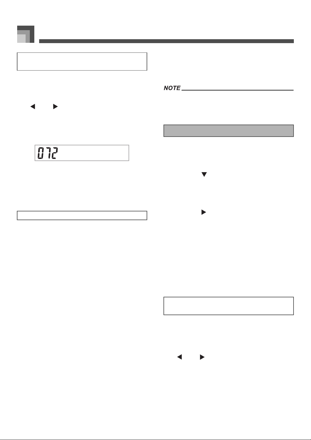
1. After selecting the reverb type you want, use the
[ ] and [ ] CURSOR buttons to display the
parameter whose setting you want to change.
• This displays the parameter setting screen.
Example:
To set the Reverb Time parameter
SimeTvR
2. Use the [+] and [–] buttons or the number buttons
to input the parameter setting you want.
3. Press the EFFECT or EXIT button.
• This returns to the tone or rhythm selection screen.
REVERB Parameters
Reverb effects are associated with either a reverb type or
delay type. Parameter settings depend upon the associated
type.
Reverb Type (No. 0 to 5, 8 to 13)
z Reverb Level (Range: 000 to 127)
Controls the reverb size. A larger number produces
larger reverb.
z Reverb Time (Range: 000 to 127)
Controls how long reverb continues. A larger
number produces longer reverb.
z ER Level (Initial Echo Sound) (Range: 000 to 127)
This parameter controls the initial reverb volume.
The initial echo sound is the first sound reflected
from the walls and ceiling when a sound is output
by this keyboard. A larger value specifies a larger
echo sound.
z High Damp (Range: 000 to 127)
Adjusts the damping of high frequency
reverberation (high sound). A smaller value damps
high sounds, creating a dark reverb. A larger value
does not damp high sounds, for a brighter reverb.
Delay Type (No. 6, 7, 14, 15)
z Delay Level (Range: 000 to 127)
Specifies the size of the delay sound. A higher value
produces a larger delay sound.
z Delay Feedback (Range: 000 to 127)
Adjusts delay repeat. A higher value produces a
greater number of repeats.
z ER Level
Same as Reverb Type
z High Damp
Same as Reverb Type
• Whether or not an effect is applied to the parts that are
sounding also depends on Mixer Mode Reverb Send,
Chorus Send, and DSP on/off settings. See “Mixer Function”
on page E-36 for more information.
Selecting CHORUS
Perform the following steps to select CHORUS.
1. Press the EFFECT button, so the pointer appears
next to EFFECT on the display screen.
2. Press the [ ] CURSOR button twice.
• This displays the chorus editing screen.
• The chorus type setting screen (step 4) will appear
automatically about fives seconds after you press the
button.
3. Press the [ ] CURSOR button.
4. Use the [
to scroll through the chorus types until the one you
want is displayed, or use the number buttons to
input the chorus number you want to select.
• See the list on page A-13 for information about the
• Here you could also change the parameters of the
Changing the Settings of CHORUS
Parameters
You can control the relative strength of an effect and how it is
applied. The parameters you can control depend on the effect.
See the following section titled “CHORUS Parameters” for
more information.
+
] and [–] buttons or the number buttons
types of CHORUS effects that are available.
effect you selected, if you want. See “Changing the
Settings of CHORUS Parameters” for more
information.
1. After selecting the chorus type you want, use the
[ ] and [ ] CURSOR buttons to display the
parameter whose setting you want to change.
2. Use the [
to input the parameter setting you want.
+
] and [–] buttons or the number buttons
3. Press the EFFECT or EXIT button.
• This returns to the tone or rhythm selection screen.
E-26
707A-E-028A
Page 30

Applying Effects to Tones
CHORUS Parameters
Chorus Level (Range: 000 to 127)
Specifies the size of the chorus sound.
Chorus Rate (Range: 000 to 127)
Specifies the undulation speed of the chorus sound. A
higher value produces faster undulation.
Chorus Depth (Range: 000 to 127)
Specifies the undulation depth of the chorus sound. A
higher value produces deeper undulation.
• Whether or not an effect is applied to the parts that are
sounding also depends on Mixer Mode Reverb Send,
Chorus Send, and DSP on/off settings. See “Mixer Function”
on page E-36 for more information.
Using the Equalizer
This keyboard has a built-in four-band equalizer and 10
different settings from which you can choose. You can adjust
the gain (volume) of all four equalizer bands within the range
of –12 to 0 to +12.
To select the equalizer type
1. Press the EFFECT button so the pointer appears
next to EFFECT on the display screen.
2. Press the [ ] CURSOR button three times.
• This displays the equalizer editing screen.
• The equalizer type setting (step 4) screen will appear
automatically about fives seconds after you press the
button.
3. Press the [ ] CURSOR button.
4. Use the [
to select the equalizer type you want.
• See the list on page A-13 for information about the
+
] and [–] buttons or the number buttons
equalizer types that are available.
Example:
To select Jazz
To adjust the gain (volume) of a band
1. After selecting the equalizer type you want, use the
[ ] and [ ] CURSOR buttons to select the band
whose gain you want to adjust.
Example:
To adjust the HIGH band
E
E
q
q
M i
2. Use the [
to adjust the band gain.
] and [–] buttons or the number buttons
+
Example:
To adjust the gain to 10
M i
• Pressing the EXIT or EFFECT button exits the
equalizer setting screen.
• Changing to another equalizer type causes the band gain
settings to change to the initial settings for the newly selected
equalizer type automatically.
g
g
hH
hH
Jzza
• Pressing the EXIT or EFFECT button exits the
equalizer setting screen.
707A-E-029A
E-27
Page 31

Auto Accompaniment
Auto Accompaniment
421 3 5
9 bl
bk86 7
bm
bn
MODE
1
RHYTHM
4
VARIATION/FILL-IN 1/2
7
TEMPO
bk
[+]/[–]
bn
This keyboard automatically plays bass and chord parts in
accordance with the chords you finger. The bass and chord
parts are played using sounds and tones that are
automatically selected to select the rhythm you are using. All
of this means that you get full, realistic accompaniments for
the melody notes you play with your right hand, creating the
mood of a one-person ensemble.
ONE TOUCH PRESET
2
EXIT
5
SYNCHRO/FILL-IN NEXT
8
AUTO HARMONIZE
bl
ACCOMP VOLUME
3
INTRO/ENDING 1/2
6
START/STOP
9
Number buttons
bm
About the MODE button
Use the MODE button to select the accompaniment mode you
want to use. Each press of the MODE button cycles through
the available accompaniment modes as shown in the
illustration below.
• Only rhythm sounds are produced when all
accompaniment mode lamps are off.
• The currently selected accompaniment mode is shown by
the mode lamps above the MODE button. Information on
using each of these modes starts from page E-30.
E-28
707A-E-030A
Page 32

Auto Accompaniment
Selecting a Rhythm
This keyboard provides you with 160 exciting rhythms that
you can select using the following procedure.
You can also transfer accompaniment data from your
computer and store up to 16 of them as user rhythms in
keyboard memory. See “Using the Music Data Management
Software (on the Bundled CD-ROM)” on page E-76 for more
information.
To select a rhythm
1. Find the rhythm you want to use in the rhythm list
and note its rhythm number.
•
Not all of the available rhythms are shown on the
rhythm list printed on the keyboard console. For a
complete list, see the “Rhythm List” on page A-
10.
2. Press the RHYTHM button.
8a1teB
12
Appears when RHYTHM button is pressed
1
Number and name of selected rhythm
2
3. Use the number buttons to input the three digit
rhythm number for the rhythm you want to select.
Example:
To select “052 ROCK 2”, input 0, 5 and then 2.
Playing a Rhythm
To play a rhythm
1. Press VARIATION/FILL-IN button 1 or 2.
• This starts the play of the selected rhythm.
• To stop rhythm play, press the START/STOP button.
• Chords will sound along with the rhythm if any of the three
accompaniment mode lamps above the MODE button is lit. if
you want to play the rhythm pattern without chords, press the
MODE button until all of the lamps are off.
Adjusting the Tempo
You can adjust the tempo of rhythm play within a range of 30
to 255 beats per minute. The tempo setting is used for Auto
Accompaniment chord play, and song memory operations.
To adjust the tempo
Press one of the TEMPO buttons ( or ).
: Increments displayed value (increases tempo)
: Decrements displayed value (decreases tempo)
Rk2co
• You can also increment the displayed rhythm number by
pressing [+] and decrement it by pressing [–].
707A-E-031A
• Pressing both TEMPO buttons ( and ) at the same time
resets the tempo to the default value of the currently selected
rhythm.
E-29
Page 33

Auto Accompaniment
1 2
Using Auto Accompaniment
The following procedure describes how to use the keyboard’s
Auto Accompaniment feature. Before starting, you should
first select the rhythm you want to use and set the tempo of
the rhythm to the value you want.
To use Auto Accompaniment
1. Use the MODE button to select FULL RANGE
CHORD, FINGERED, or CASIO CHORD as the
accompaniment mode.
2. Press the START/STOP button to start play of the
currently selected rhythm.
3. Play a chord.
• The actual procedure you should use to play a chord
depends on the currently selected accompaniment
mode. Refer to the following pages for details on
chord play.
CASIO CHORD : Page E-30
FINGERED : Page E-31
FULL RANGE CHORD : Page E-31
Rk2co
Chord name
1
Current measure number and beat number
2
Basic fingering of current chord
3
(May be different from chord actually being played
on the keyboard.)
4. To stop Auto Accompaniment play, press the
START/STOP button again.
• If you press the SYNCHRO/FILL-IN NEXT button and then
the VARIATION/FILL-IN 1/2 buttons in place of the START/
STOP button in step 2, accompaniment will start with an intro
pattern when you perform the operation in step 3. For details
about these buttons, see pages E-32 and E-33.
• If you press the VARIATION/FILL-IN 1/2 buttons in place of
the START/STOP button in step 4, an ending pattern will
play before accompaniment play is ended. For details about
this button, see page E-33.
• You can adjust the accompaniment part volume level
independently of the main volume. For details, see
“Adjusting the Accompaniment Volume” on page E-35.
CASIO CHORD
This method of chord play makes it possible for anyone to
easily play chords, regardless of previous musical knowledge
and experience. The following describes the CASIO CHORD
“accompaniment keyboard” and “melody keyboard,” and
tells you how to play CASIO CHORDs.
J CASIO CHORD Accompaniment Keyboard and
Melody Keyboard
• The accompaniment keyboard can be used for playing
chords only. No sound will be produced if you try playing
single melody notes on the accompaniment keyboard.
J Chord Types
CASIO CHORD accompaniment lets you play four types of
chords with minimal fingering.
Chord Types
Major chords
Major chord names are marked
above the keys of the
accompaniment keyboard. Note
that the chord produced when you
press an accompaniment keyboard
does not change octave, regardless
of which key you use to play it.
Minor chords (m)
To play a minor chord, keep the
major chord key depressed and
press any other accompaniment
keyboard key located to the right
of the major chord key.
Seventh chords (7)
To play a seventh chord, keep the
major chord key depressed and
press any other two
accompaniment keyboard keys
located to the right of the major
chord key.
Minor seventh chords (m7)
To play a minor seventh chord,
keep the major chord key
depressed and press any other
three accompaniment keyboard
keys located to the right of the
major chord key.
C Major (C)
C minor (Cm)
C seventh (C7)
C minor seventh (Cm7)
Example
E-30
707A-E-032A
Page 34

Auto Accompaniment
• It makes no difference whether you press black or white keys
to the right of a major chord key when playing minor and
seventh chords.
FINGERED
FINGERED provides you with a total of 15 different chord
types. The following describes the FINGERED
“accompaniment keyboard” and “melody keyboard”, and
tells you how to play a C-root chord using FINGERED.
J FINGERED Accompaniment Keyboard and Melody
Keyboard
• The accompaniment keyboard can be used for playing
chords only. No sound will be produced if you try playing
single melody notes on the accompaniment keyboard.
• Except for the chords specified in note*1above, inverted
fingerings (i.e. playing E-G-C or G-C-E instead of C-E-G) will
produce the same chords as the standard fingering.
• Except for the exception specified in note*
keys that make up a chord must be pressed. Failure to press
even a single key will not play the desired FINGERED chord.
2
above, all of the
FULL RANGE CHORD
This accompaniment method provides a total of 38 different
chord types: the 15 chord types available with FINGERED
plus 23 additional types. The keyboard interprets any input of
three or more keys that matches a FULL RANGE CHORD
pattern to be a chord. Any other input (that is not a FULL
RANGE CHORD pattern) is interpreted as melody play.
Because of this, there is no need for a separate
accompaniment keyboard, so the entire keyboard, from end
to end, functions as a melody keyboard that can be used for
both melody and chords.
J FULL RANGE CHORD Accompaniment Keyboard
and Melody Keyboard
See the “Fingered Chord Chart” on page A-11 for details on
playing chords with other roots.
*1 Inverted fingerings cannot be used. The lowest note is the
root.
*2 The same chord can be played without pressing the 5th G.
Chords Recognized by This Keyboard
The following table identifies patterns that are recognized
as chords by FULL RANGE CHORD.
Pattern Type Number of Variations
The 15 chord patterns shown under
FINGERED
Standard
Fingerings
FINGERED on page E-31. See the
“Fingered Chord Chart” on page A-11
for details on playing chords with other
roots.
23 standard chord fingerings. The
following are examples of the 23 chords
available with C as the bass note.
707A-E-033A
E-31
Page 35

Auto Accompaniment
Example:
To play the chord C major.
Any of the fingerings shown in the illustration below will
produce C major.
• As with the FINGERED mode (page E-31), you can play the
notes that form a chord in any combination (1).
• When the lowest note of a chord is separated from its
neighboring note by six or more semitones, the lowest note
becomes the bass note (2).
Using a Fill-in Pattern
Fill-in patterns let you momentarily change the rhythm
pattern to add some interesting variation to your
performances.
The following procedure describes how to use the Fill-in
feature.
To insert a fill-in
1. Press the START/STOP button to start rhythm
play.
2. Select the fill-in variation you want.
• To insert Fill-in 1, press the VARIATION/FILL-IN 1
button while Variation 1 of the rhythm is playing.
• To insert Fill-in 2, press the VARIATION/FILL-IN 2
button while Variation 2 of the rhythm is playing.
Using an Intro Pattern
This keyboard lets you insert a short intro into a rhythm
pattern to make startup smoother and more natural.
The following procedure describes how to use the Intro
feature. Before starting , you should first selec t the rhythm you
want to use, set the tempo, and use the MODE button to select
the chord play method you want to use (NORMAL, CASIO
CHORD, FINGERED, FULL RANGE CHORD).
To insert an intro
1. Press INTRO/ENDING button 1 or 2.
• With the above setup, the intro pattern is played and
the auto accompaniment with intro pattern starts as
soon as you play chords on the accompaniment
keyboard.
• The standard rhythm pattern starts to play after the intro
pattern is complete.
• Only the SYNCHRO/FILL-IN NEXT button is operational
while an intro is playing.
• Holding down the SYNCHRO/FILL-IN NEXT or VARIATION/
FILL-IN 1/2 buttons causes the fill-in pattern to repeat.
Using a Rhythm Variation
In addition to the standard rhythm pattern, you can also
switch to a secondary “variation” rhythm pattern for a bit of
variety.
To insert the variation rhythm pattern
1. Press the START/STOP button to start rhythm
play.
2. Press the SYNCHRO/FILL-IN NEXT button.
• If a Variation 1 rhythm is currently playing, this plays
Fill-in 1, followed by Fill-in 2, and then switches to the
Variation 2 rhythm.
• If a Variation 2 rhythm is currently playing, this plays
Fill-in 2, followed by Fill-in 1, and then switches to the
Variation 1 rhythm.
• Holding down the SYNCHRO/FILL-IN NEXT button
causes the fill-in pattern to repeat.
E-32
707A-E-034A
Page 36

Auto Accompaniment
Synchro Starting Accompaniment
with Rhythm Play
You can set up the keyboard to start rhythm play at the same
time you play the accompaniment on the keyboard.
The following procedure describes how to use synchro start.
Before starting, you should first select the rhythm you want to
use, set the tempo, and use the MODE button to select the
chord play method you want to use (NORMAL, CASIO
CHORD, FINGERED, FULL RANGE CHORD).
To use synchro start
1. Press the SYNCHRO/FILL-IN NEXT button to put
the keyboard into synchro start standby.
2. Play a chord and the rhythm pattern starts to play
automatically.
• If the MODE button is set to NORMAL, only the rhythm plays
(without a chord) when you play on the accompaniment
keyboard.
• If you press the INTRO/ENDING button 1 or 2 before playing
anything on the keyboard, the rhythm starts automatically
with an intro pattern when you play something on the
accompaniment keyboard.
• To cancel synchro start standby, press the SYNCHRO/FILLIN NEXT button one more time.
Finishing with an Ending
Pattern
You can end your performances with an ending pattern that
brings the rhythm pattern you are using to a naturalsounding conclusion.
The following procedure describes how to insert an ending
pattern. Note that the actual ending pattern played depends
on the rhythm pattern you are using.
To finish with an ending pattern
1. While the rhythm is playing, press INTRO/
ENDING button 1 or 2.
• The timing when the ending pattern starts depends on
when you press the INTRO/ENDING button 1 or 2. If
you press the button before the second beat of the
current measure, the ending pattern starts playing
immediately.
• Pressing the INTRO/ENDING button prior to the first half
beat at the beginning of a measure plays the ending
immediately. Pressing the button after the first half beat of a
measure causes the ending to be played from the beginning
of the following measure.
707A-E-035A
E-33
Page 37

Auto Accompaniment
Using One-touch Preset
One-touch preset automatically makes the main settings
listed below in accordance with the rhythm pattern you are
using.
•Keyboard tone
•Layer on/off
•Split on/off
• Auto Harmonize on/off
• Auto Harmonize type
• Accompaniment volume level
•Tempo
• Effect settings
To use one-touch preset
1. Select the rhythm you want to use.
2. Use the MODE button to select the
accompaniment mode you want to use.
3. Press the ONE TOUCH PRESET button.
• This automatically makes the one-touch preset
settings in accordance with the rhythm you selected.
• The keyboard automatically enters synchro standby at
this time.
4. Start rhythm and Auto Accompaniment, and play
something on the keyboard.
• Accompaniment is played using the one-touch preset
settings.
Using Auto Harmonize
When you are using Auto Accompaniment, Auto Harmonize
automatically adds additional notes to your melody in
accordance with the chord that is being played. The result is a
harmony effect that makes your melody line richer and fuller.
To use Auto Harmonize
1. Use the MODE button to select FINGERED or
CASIO CHORD as the accompaniment mode.
• The currently selected accompaniment mode is the
one whose lamp is lit. See “About the MODE button”
on page E-28 for details.
2. Press AUTO HARMONIZE to turn on Auto
Harmonize.
• This causes a pointer to appear next to AUTO
HARMONIZE on the display.
E-34
3. Start Auto Accompaniment play, and play
something on the keyboard.
4. To turn off Auto Harmonize, press AUTO
HARMONIZE once.
• This causes the pointer next to AUTO HARMONIZE
to disappear.
• Auto Harmonize turns off temporarily whenever you start
demo tune play. It turns back on as soon as the operation or
function that caused it to turn off is finished.
• Auto Harmonize is enabled only when the Auto
Accompaniment mode is FINGERED or CASIO CHORD.
707A-E-036A
Page 38

Auto Accompaniment
1
Auto Harmonize Types
Auto Harmonize lets you select from among the 10 Auto
Harmonize types. Type changing is performed by the setting
item using the TRANSPOSE/FUNCTION button.
See “Changing Other Settings” on page E-66 for more
information.
About Auto Harmonize notes and tones
The notes you play on the keyboard are called “melody
notes,” while the notes added to the melody by Auto
Harmonize is called the “harmonize notes.” Auto Harmonize
normally uses the tone you selected for the melody notes as
the tone for the harmonize notes, but you can use the Mixer
(page E-36) to specify a different tone for the harmonize notes.
The harmonize note tone is assigned to Mixer Channel 5, so
change Channel 5 to the tone you want to use for the
harmonize notes.
In addition to the tone, you can also use the Mixer to change
a number of other parameters, such as volume balance. See
“Using the Parameter Edit Mode” on page E-37 for details on
these procedures.
• The default harmonize note tone when you first turn on Auto
Harmonize is the same tone as the melody note tone.
• Changing the melody tone setting automatically changes the
harmonize note tone to the same setting.
Adjusting the Accompaniment
Volume
You can adjust the volume of the accompaniment parts as a
value in the range of 000 (minimum) to 127 (maximum).
1. Press the ACCOMP VOLUME button.
AmVol
Current accompaniment volume setting
1
p
oc
2. Use the number buttons or the [+]/[–] buttons to
change the current volume setting value.
Example: 110
AmVol
• Pressing the ACCOMP VOLUME button or EXIT button
returns to the tone or rhythm setting screen.
• Any channel balance settings you make with the Mixer are
maintained when you change the accompaniment volume
setting.
• Pressing [+] and [–] buttons at the same time automatically
sets an accompaniment volume of 100.
p
oc
707A-E-037A
E-35
Page 39

Mixer Function
Mixer Function
1 2 3
6
7
54
MIXER
1
EXIT
4
[+]/[–]
7
DRAWBAR ORGAN
2
[ ]/[ ]/[ ]/[ ] CURSOR
5
What you can do with the Mixer
This keyboard lets you play multiple different musical
instrument parts at the same time during auto-accompaniment
play, song memory playback, receipt of data through the MIDI
terminal, etc. The Mixer assigns each part to a separate channel
(1 through 16) and lets you control the channel on/off, volume,
and pan pot parameters of each channel.
In addition to channels 1 through 16, the Mixer also has a DSP
channel that you can use to adjust the DSP level, DSP pan, and
other DSP parameters.
Channel Assignments
The following shows the parts that are assigned to each of the
16 channels.
Channel
Number
Channel 1 Main tone
Channel 2 Layered tone
Channel 3 Split tone
Channel 4 Layered/split tone
Channel 5 Harmonize Tone
Channel 6 Auto Accompaniment chord part 1
Channel 7 Auto Accompaniment chord part 2
Channel 8 Auto Accompaniment chord part 3
Channel 9 Auto Accompaniment bass part
Channel 10 Auto Accompaniment rhythm part
Channel 11 Song Memory track 1
Channel 12 Song Memory track 2
Channel 13 Song Memory track 3
Channel 14 Song Memory track 4
Channel 15 Song Memory track 5
Channel 16 Song Memory track 6
Part
TONE
3
Number buttons
6
See pages E-61 to E-63 for information on layered, split, and
layered/split tones.
See page E-49 for information on the song memory.
• Normally, keyboard play is assigned to Channel 1. When
Auto Accompaniment is being used, each part of the
accompaniment is assigned to Channels 6 through 10.
• When this keyboard is being used as the sound source for an
externally connected computer or other MIDI device, all 16
channels are assigned musical instrument parts. The notes
played over the channel selected by steps 1 and 2 under
“Turning Channels On and Off” on page E-36 are shown on
the displayed keyboard and staff.
Turning Channels On and Off
Turning a channel off mutes any instrument recorded in the
channel.
To turn channels on and off
1. Press the MIXER button.
• This causes a pointer to appear on the display next to
MIXER.
2. Use the [ ]/[ ] CURSOR buttons to select a
channel.
Example:
To select Channel 1.
1
Flash
1
• This causes the upper three segments of the selected
channel's level meter to flash.
E-36
707A-E-038A
Page 40

3. Press the [ ]/[ ] CURSOR buttons to display
the on/off selection screen.
Mixer Function
Using the Parameter Edit Mode
Cnelnah
4. Use the [
+
]/[–] buttons to select on or off.
Example:
To turn the channel off.
Cnelnah
• Press the [ ] CURSOR button to return to the
channel selection screen.
• Pressing the MIXER button returns to the Tone Screen.
• The MIDI data display shows only the data for the channels
selected with the Mixer.
How Channel On/Off Works
The following describes what happens and what appears on
the display when you turn a channel on or off.
z On (on)
This setting turns on the currently selected channel, which is
indicated by a bar appearing at the bottom of the level meter
for that chann el. This is also the defa ult setting for all cha nnels
when the keyboard is turned on.
z Off (oFF)
This setting turns off the currently selected channel, which is
indicated by the absence of the bar at the bottom of the level
meter for that channel.
Editing the Parameters for Channels 1
through 16
In the Parameter Edit Mode, you can change the settings of
ten different parameters (including tone, volume, and pan
pot) for the channel you selected on the Mixer screen.
To change parameters
1. Press the MIXER button.
• This causes a pointer to appear on the display next to
MIXER.
2. Use the [ ] and [ ] CURSOR buttons to select
the channel you want.
3. Use the [ ] and [ ] CURSOR buttons to select
the parameter whose setting you want to change.
Example:
Select volume setting by displaying “Volume”.
• Each press of the [ ] or [ ] CURSOR buttons cycles
through the parameters.
• You can use the [ ] and [ ] CURSOR buttons to
change to another channel at any time during this
procedure.
Vuemlo
1
Indicates channel volume of 127
1
4. Use the number buttons or [
the parameter setting.
Example:
Change the setting to “060”.
+
] and [–] to change
707A-E-039A
On
1
Off
2
• Pressing the MIXER or EXIT button exits the
parameter edit mode.
Vuemlo
E-37
Page 41

Mixer Function
Editing DSP Channel Parameters
1. While Channel 16 is selected, press the [ ]
CURSOR button.
• This selects the DSP channel.
• Pressing the [ ] CURSOR button while the DSP
channel is selected returns to Channel 16.
How Parameters Work
The following are the parameters whose settings can be
changed in the Parameter Edit Mode.
Tone Parameters
z Tone (Range: 000 to 903, Drawbar organ tones 000 to 199)
This parameter controls the tones assigned to each part.
Anytime the tone is on the display, you can use the TONE
button or DRAWBAR ORGAN button and then select a
different tone, if you want.
SGPnor.t
z Octave Shift (Range: –2 to 0 to +2)
You can use octave shift to shift the range of the tone up or
down. When using the piccolo tone, there may be cases when
very high notes you want to play are not included within the
range of the keyboard. When this happens, you can use
octave shift to shift the keyboard range one octave up.
OSifthtc
–2 :Range shifted two octaves down.
–1 :Range shifted one octave down.
0 :No shift
+1 :Range shifted one octave up.
+2 :Range shifted two octaves up.
Tuning Parameters
You can use these parameters to tune each of the parts
individually.
z Coarse Tune (Range: –24 to 00 to +24)
This parameter controls the coarse tuning of the selected
channel’s pitch in semitone units.
z Part On/Off (Settings: on, oFF)
This parameter can be used to turn ea ch par t on (sounds) and
off (does not sound). The current on/off status of each part is
indicated on the display as described below.
Cnelnah
z Volume (Range: 000 to 127)
This is the parameter that controls the volume of the selected
channel.
Vuemlo
z Pan Pot (Range: –64 to 00 to +63)
This parameter controls the pan pot, which is the center point
of the left and right stereo channels. Setting “00” specifies
center, a value less than “00” moves the point left, and a value
greater than “00” moves it right.
Pna
CuenT.
z Fine Tune (Range: –99 to 00 to +99)
This parameter controls the fine tuning of the selected
channel’s pitch in cent units.
FeuneTni
Effect Parameters
The Mixer lets you control the effects applied to each
individual part, making it different from the Effect Mode,
whose settings are applied to all parts in general.
z Reverb Send (Range: 000 to 127)
This parameter controls how much reverb is applied to a part.
A setting of “000” turns reverb off, while a setting of 127
applies maximum reverb.
• “Reverb Send” does not work with some drum sounds.
RendSbv
E-38
707A-E-040A
Page 42

z Chorus Send (Range: 000 to 127)
This parameter controls how much chorus send is applied to
a part. A setting “000” turns chorus send off, while a setting
of 127 applies maximum chorus send.
• “Chorus Send” does not work with drum sounds.
CendSoh
z DSP Line (Settings: on, oFF)
You can use this parameter to turn DSP line off for a particular
channel, or to turn it on.
DineLPS
DSP Part Parameters
z DSP Level (Range: 0 to 127)
Sets the post-DSP volume.
Mixer Function
• Changing the tone, volume, pan pot, coarse tune, fine tune,
reverb send, or chorus send setting causes the
corresponding MIDI message to be output from the MIDI
terminal.
• Changing the tone settings changes the tone, octave shift,
reverb send, chorus send, and DSP line* parameter settings.
* When DSP is off (See the note on page E-24).
• Turning on the Mixer’s DSP line parameter (page E-24)
causes the settings of the DSP Pan, DSP System Reverb
Send, and DSP System Chorus parameters to be used in
place of the Pan Pot, Reverb Send, and Chorus Send
parameter’s settings.
DLvelePS
z DSP Pan (Range: –64 to 0 to 63)
Sets the post-DSP stereo pan.
DanPPS
z DSP System Reverb Send (Range: 000 to 127)
This parameter adjusts how much reverb is applied to all
parts.
DvSndbR.
z DSP System Chorus Send (Range: 000 to 127)
This parameter adjusts chorus.
DhSndoC.
707A-E-041A
E-39
Page 43

Synthesizer Mode
Synthesizer Mode
1
SYNTH
1
Number buttons
4
The Synthesizer Mode of this keyboard provides the tools for
creating your own original tones. Simply select one of the
built-in tones and change its parameters to create your own
original sound. You can even store your sounds in memory
and select it using the same procedure as that used to select a
preset tone.
EXIT
2
[+]/[–]
5
Synthesizer Mode Functions
The following describes how to use each of the functions
available in the Synthesizer Mode.
2
3
[ ]/[ ]/[ ]/[ ] CURSOR
3
4
5
Synthesizer Mode Parameters
The preset tones that are built into this keyboard consist of a
number of parameters. To create a user tone, you first recall
an advanced tone (000 to 331) or a preset tone (400 to 599) and
then change its parameters to change it to your own tone.
Note that drum set tones (600 through 617) cannot be used as
the basis of a user tone.
The illustration nearby shows the parameters that make up
the preset tones and what each parameter does. As can be
seen in the illustration, parameters can be divided into four
groups, each of which is described in detail below.
• Note that the tone whose parameter you can edit is the one
assigned to the channel (1 through 4) that is currently
selected with the Synthesizer Mode.
E-40
707A-E-042A
Page 44

Synthesizer Mode
J Tone Characteristic Waveform
z Tone Setting
Specifies which of the preset tones should be used as the
original tone.
J Volume Characteristic Parameters
These parameters control how the tone changes over time,
from when the keyboard key is pressed until the tone decays.
You can specify changes in volume and sound characteristics.
z Attack time
This is the rate or time it takes for the tone to reach its highest
volume level. You can specify a fast rate, where the tone
reaches its highest volume level immediately, a slow rate
where it gradually rises, or something in between.
z Release time
z Cutoff Frequency
The cutoff frequency is a parameter for adjusting timbre by
cutting any frequency that is higher than a specific frequency.
A larger cutoff frequency produces a brighter (harder) timbre,
while a smaller frequency produces a darker (softer) timbre.
z Resonance
Resonance enhances the harmonic components in the vicinity
of the cutoff frequency, which creates a distinctive sound. A
larger resonance value enhances the sound as shown in the
figure.
• With some tones, a large resonance value can cause
distortion or noise during the attack part of the tone.
J Tone Pitch Parameters
z Vibrato Type, Vibrato Delay, Vibrato Rate, Vibrato Depth
These parameters adjust the vibrato effect, which causes
periodic changes in the tone.
z Octave Shift
This parameter controls the octave of all tones.
J Tone Characteristic Setting Parameters
z Level
This parameter controls the overall volume of the tone.
z Touch Sense
This parameter controls changes in volume and timbre in
accordance with the relative amount of pressure applied to
the keyboard keys. You can specify more volume for stronger
pressure and less volume or a lighter pressure, or you can
specify the same volume regardless of how much pressure is
applied to the keys.
z Reverb Send, Chorus Send, DSP Line , DSP Type, DSP
Parameter
These parameters control the effects applied to tones.
707A-E-043A
E-41
Page 45

Synthesizer Mode
Saving User Tones
The group of tone numbers from 700 through 799 (User 001 through User 100) is called the “user area” because they are reserved
for storage of user tones. After you recall a preset tone and change its parameters to create your own user tone, you can store it in
the user area for later recall. You can recall your tones using the same procedure that you use when selecting a preset tone.
*1: You can select any Advanced Tone, preset tone, or user tone. User tone areas 700 through 799 initially contain the same data
as advanced tones 000 through 099.
*2: Area where data transferred from computer is stored (see “Using the Music Data Management Software (on the Bundled CD-
ROM)” on page E-76). After transfer, you can use the keyboard to edit parameters, but you can only overwrite existing
parameters. You cannot save the data to another number.
*3: Area where data transferred from computer is stored (see “Using the Music Data Management Software (on the Bundled CD-
ROM)” on page E-76). Transfer only is allowed, and no parameter editing is allowed.
*4: User tones created by modifying parameters of one of the preset tones (000 to 049). User drawbar organ tone areas initially
contain two sets of the same data as drawbar organ tones types 000 through 049.
• You can create an original tone using a user tone that includes a waveform (tone number 800 to 819). In this case, the storage area is
the same as the source tone area. For example, an original tone created using tone number 800 as a source tone is stored in user area
number 800.
E-42
707A-E-044A
Page 46

Synthesizer Mode
Creating a User Tone
Use the following procedure to select a preset tone and
change its parameters to create a user tone.
1. First, select the preset tone you want to use as a
basis for your user tone.
2. Press the SYNTH button.
• This enters the Synthesizer Mode, which is indicated
by the pointer next to SYNTH on the display screen.
AimeTkt
1 2
Parameter setting value
1
Currently selected parameter
2
3. Use the [ ] and [ ] CURSOR buttons to display
the parameter whose setting you want to change.
VDla
• Each press of the [ ] or [ ] CURSOR buttons
changes to the next parameter. See “Parameters and
Their Settings” on page E-43 for information on setting
range for each parameter.
4. Use [
+
] and [–] to change the setting of the
currently selected parameter.
• You can also use the number buttons to input a value
to change a parameter setting. See “Parameters and
Their Settings” on page E-43 for information on setting
range for each parameter.
ebi
5. After you are finished editing the sound, press the
SYNTH button to exit the Synthesizer Mode.
y
Parameters and Their Settings
The following describes the function of each parameter and
provides its setting range.
z Attack Time (Range: –64 to 00 to +63)
Time it takes before the tone sounds after a key is pressed
AimeTkt
z Release Time (Range: –64 to 00 to +63)
Time the tone continues to sound after a key is released
R.imeTle
z Cutoff Frequency
(Range: –64 to 00 to +63)
High-band cutoff for the harmonic components of the tone
y
p
q
.
eTbi
CfFr
z Resonance (Range: –64 to 00 to +63)
Resonance of the tone
Roan
z Vibrato Waveform (Range: See below.)
Specifies the vibrato waveform.
fo-
nse
V.
• See “Storing a User Tone In Memory” on page E-45 for
details on saving user tone data to memory so it is not
deleted.
707A-E-045A
Value Meaning Waveform
Sin Sine Wave
tri Triangle Wave
SAU Sawtooth Wave
Sqr Square Wave
E-43
Page 47

Synthesizer Mode
z Vibrato Delay (Range: –64 to 00 to +63)
Specifies the amount of time before vibrato starts.
VDla
z Vibrato Rate (Range: –64 to 00 to +63)
Rate (speed) of the vibrato effect
ebi
y
V . ateRbi
z Vibrato Depth (Range: –64 to 00 to +63)
Depth of the vibrato effect
VD
z Octave Shift (Range: –2 to 0 to +2)
Up/down octave shift
p
thebi
OSifthtc
z Level (Range: 000 to 127)
This parameter controls the overall volume of the tone. The
greater the value, the greater the volume. Setting a level of
zero means that the tone does not sound at all.
Lelve
Touch Sensitivity (Range: –64 to 00 to +63)
This parameter controls changes in the volume of the tone in
accordance with the pressure applied to the keyboard keys. A
greater positive value increases the volume of the output as
pressure increases, while a negative value decreases volume
with increased keyboard pressure. A setting of zero specifies
no change in output volume in accordance with keyboard
pressure.
z Reverb Send (Range: 000 to 127)
This parameter adjusts reverb.
R endSbv
z Chorus Send (Range: 000 to 127)
This parameter adjusts chorus.
C endSoh
z DSP Line (Settings: on, oFF)
This parameter controls whether or not the DSP effect is used.
D ineLPS
DSP Settings
Use the DSP editing screen to select the DSP type and to edit
parameters.
1. Select a tone, press the SYNTH button, and then
configure parameter settings.
2. After everything is the way you want, press the
[ ] CURSOR button once. This advances to the
DSP parameter editing screen.
Pressing the [ ] CURSOR button returns to the Synthesizer
Mode parameter screen.
This setting specifies DSP parameters. See “DSP Parameters”
on page E-24, “Effect List” on page A-13, and “DSP Algorithm
List” on page E-83 for more information.
• If you store an original tone with the DSP line turned on (see
next page), simply recalling the tone automatically changes
the DSP line, DSP type, and DSP parameter settings. This
simplifies the recall of original tones that include a DSP
effect.
• An indicator appears next to DSP on the display while you
are making DSP type or DSP parameter settings.
E-44
T S nseehc
707A-E-046A
Page 48

Synthesizer Mode
User Tone Creation Hints
The following hints provide helpful advice on making user
tone creation a bit quicker and easier.
Use a preset tone that is similar to the one you are trying to
create.
Whenever you already have a rough idea of the tone you are
trying to create, it is always a good idea to start with a preset
tone that is similar.
z Experiment with various different settings.
There are no real rules about what a tone should sound like.
Let your imagination run free and experiment with different
combinations. You may be surprised at what you can achieve.
Storing a User Tone In Memory
The following procedure shows how to store a user tone in
memory. Once a tone is stored, you can call it up just as you
do with a preset tone.
To name a user tone and store it in memory
1. Select a preset tone to use as the basis for the
user tone, press the SYNTH button to enter the
Synthesizer Mode, and make the parameter
settings you want.
2. After making parameter settings to create the user
tone, press the [ ] CURSOR button twice.
3. Use [+] and [–] to change the user area tone
number on the display until the one where you
want to store the tone is shown.
• You can select any tone number from 700 to 799.
5. Press the [ ] CURSOR button to save the user
tone.
• This will display a confirmation message asking
whether you really want to save the data. Press the
YES button to save the data.
• The message “Complete” appears momentarily on the
display, followed by the tone or rhythm selection
screen.
• To abort the save operation at any time, press the
SYNTH button or the EXIT button to exit the
Synthesizer Mode. Pressing the SYNTH button again
(before selecting another tone) returns to the
Synthesizer Mode with all of your parameter settings
still in place.
Inputting Characters
The following are the types of characters you can input when
saving data to the user area.
4. After the tone name is the way you want, press the
[ ] CURSOR button to store the tone.
•Use the [+] and [–] buttons to scroll through letters at
the current cursor location.
• Use the [ ] and [ ] CURSOR buttons to move the
cursor left and right.
• See “Inputting Characters” for information about
inputting text.
707A-E-047A
E-45
Page 49

Registration Memory
Registration Memory
1
5
2 43
1
4
MODE
STORE
BANK
2
Number buttons
5
Registration Memory Features
Registration memory lets you store up to 32 keyboard setups
(4 sets × 8 banks) for instant recall whenever you need them.
The following is a list of settings that are saved in registration
memory.
Registration Memory Settings
•Tone
•Rhythm
•Tempo
•Layer on/off
•Split on/off
• Split point
• Auto Harmonize on/off
• Mixer settings (Channels 1 to 10)
• Effect settings
• Touch Response settings
• Assignable jack setting
•Transpose
•Tuning
• Accompaniment volume setting
• Auto Harmonize type
• MODE button setting
• Synchro standby state
•Mixer Hold
•DSP Hold
• Synthesizer Mode parameters (Vibrato Waveform, Vibrato
Delay, Vibrato Rate, and Vibrato Depth only)
REGISTRATION
3
• Each bank of registration memory initially contains data
when you first use the keyboard. Simple replace the existing
data with your own data.
• Registration memory functions are disabled while you are
using the SMF Player, Song Memory or demo tune function.
E-46
707A-E-048A
Page 50

Registration Memory
Setup Names
You can assign setups into one of 32 areas, which you can
select using BANK buttons 1 through 4 and the four
REGISTRATION buttons. Area names range from 1-1
through 8-4 as shown below.
Use the BANK button to select the bank. Each press of
1
BANK cycles through the bank numbers from 1 to 8.
Pressing one of the REGISTRATION buttons (1 to 4)
2
selects the corresponding area in the currently selected
bank.
• Whenever you save a setup and assign it a setup name, any
setup data previously assigned to that name is replaced with
the new data.
• You can use the keyboard’s MIDI capabilities to save your
setup data to a computer or other external storage device.
See “Using the Music Data Management Software (on the
Bundled CD-ROM)” on page E-76 for details.
To Save a Setup in Registration
Memory
1. Select a tone and rhythm, and otherwise set up the
keyboard the way you want it.
• See “Registration Memory Features” on page E-46 for
details on what data is stored in the registration
memory.
2. Use the BANK button or the number buttons to
select the bank you want.
• If you do not perform any operation for about five
seconds after pressing the BANK button, the display
returns to the contents in step 1, above.
• Bank 1 selected.
Bkna
3. While holding down the STORE button, press a
REGISTRATION button (1 to 4).
• The following display appears when you press the 2
button.
Sreot
4. Release the STORE and REGISTRATION
buttons.
• The setup is saved as soon as you press a REGISTRATION
button in step 3, above.
707A-E-049A
E-47
Page 51

Registration Memory
To Recall a Setup from
Registration Memory
1. Use the BANK button or the number buttons to
select the bank.
• If you do not perform any operation for about five
seconds after pressing the BANK button, the keyboard
automatically clears the registration memory recall
screen.
Bkna
2. Press the REGISTRATION button (1 to 4) for the
area whose setup you want to recall.
Rallce
• The setup name along with the message “Recall”
appears on the display.
• If you press a REGISTRATION button without using the
BANK button to select a bank first, the last bank number
selected is used.
E-48
707A-E-050A
Page 52

Song Memo ry Functio n
Song Memory Function
2 41
9 bk86 7
MODE
1
DRAWBAR ORGAN
4
VARIATION/FILL-IN 1/2
7
TEMPO
bk
[+]/[–], YES/NO
bn
This keyboard lets you record up to five separate songs in
song memory for later playback. There are two methods you
can use to record a song: real-time recording where you
record the notes as you play them on the keyboard, and step
recording where you input chords and notes one-by-one.
• Layer and split cannot be used while standing by for
recording or while recording is being performed in the Song
Memory Mode. Also, layer and split are automatically turned
off whenever the keyboard goes into record standby or starts
recording.
SONG MEMORY
2
[ ]/[ ]/[ ]/[ ] CURSOR
5
SYNCHRO/FILL-IN NEXT
8
SONG MEMORY TRACK
bl
3 5
bm
bn
bl
TONE
3
INTRO/ENDING 1/2
6
START/STOP
9
Number buttons
bm
Tracks
Keyboard song memory records and plays back much like a
standard tape recorder. There are a total of six tracks, each of
which can be recorded separately. Besides notes, each track
can have its own tone number. Then when you play back the
tracks together, it sounds like an entire six-piece band. During
playback, you can adjust the tempo to change the speed of
playback.
707A-E-051A
• With this keyboard, Track 1 is the basic track, which can be
used to record keyboard play, along with Auto
Accompaniment. Tracks 2 through 6 can be used for
keyboard play, so they are called melody tracks. Tracks 2
through 6 are used to add other parts to what is recorded in
Track 1.
• Note that each track is independent of the others. This
means that even if you make a mistake while recording, you
only need to re-record the track where the mistake was
made.
• You can use different Mixer settings for each track (page
E-36).
E-49
Page 53

Song Memory Function
1 2 4 63 5
1
Selecting a Track
Use the SONG MEMORY TRACK buttons marked CHORD/
TR1 through TR6 to select the track you want.
J SONG MEMORY TRACK Buttons
Track 1
1
Track 2
2
Track 3
3
Track 4
4
Track 5
5
Track 6
6
Basic Song Memory operations
The status of the Song Memory changes each time you press
the SONG MEMORY button.
Using Real-time Recording
With real-time recording, the notes you play on the keyboard
are recorded as you play them.
To record with real-time recording
1. Press the SONG MEMORY button twice to enter
real-time record standby.
• Perform step 2, below, within five seconds after
entering record standby.
• The level meters for tracks 11 through 16 are shown on
the display while the keyboard is in record standby, so
you can easily check which tracks are already
recorded. See “Level Meter Contents During Record/
Edit Standby” on page E-57 for details.
2. Use the number buttons to select a song number
(0 to 4).
Rodrce
E-50
Song number
1
• The above song number screen remains on the display
for about five seconds. If it disappears before you have
a chance to select a song number, use the [ ]
CURSOR button to re-display it.
3. Make the following settings.
•Tone number
• Rhythm number
•Tempo
•MODE button
4. Press the START/STOP button to start recording.
•
Real-time recording without a rhythm starts. If you want
to record with a rhythm, press the INTRO/ENDING 1/2
or VARIATION/FILL-IN 1/2
• When recording starts, the REC indicator flashes on
the display. After a few moments the indicator stops
flashing, and remains on the display.
.
707A-E-052A
Page 54

5. Play something on the keyboard.
• You can also record Auto Accompaniment chords by
selecting the applicable mode with the MODE button.
• Optional pedal operation is also recorded. See “Track
1 Contents After Real-time Recording”.
6. Press the START/STOP button to end recording
when you are finish playing.
• If you make a mistake while recording, you can stop
the record operation and begin over again from step 1,
or you can use the editing function (page E-58) to
make corrections.
• Using real-time recording to record to a track that already
contains recorded data replaces the previous recording with
the new one.
Song Memory Function
Mixer Mode Settings
Channel 1 Mixer parameters (page E-36) are automatically
recorded to Track 1. You can use the Mixer to change each of
the parameters.
Memory Capacity
The keyboard has memory for approximately 10,000 notes.
• The measure number and note number flash on the display
whenever remaining memory is less than 100 notes.
• Recording automatically stops (and auto-accompaniment
and rhythm stops playing if they are being used) whenever
memory becomes full.
• Initially, nothing is stored in song memory.
Track 1 Contents After Real-time Recording
In addition to keyboard notes and accompaniment chords,
the following data is also recorded to Track 1 during real-time
recording. This data is applied whenever Track 1 is played
back.
• Tone number
• Rhythm number
• INTRO/ENDING 1 button, INTRO/ENDING 2 button,
VARIATION/FILL-IN 1 button, VARIATION/FILL-IN 2
button, SYNCHRO/FILL-IN NEXT button operations
• Pedal operations (option)
The following data is recorded in the header whenever you
start a recording of a track.
• Mixer settings of other tracks
• Effect type
• Accompaniment volume
• Reverb Level
•Chorus Level
• DSP Hold On/Off
• Mixer Hold On/Off
Memory Data Storage
• Whenever you make a new recording, anything previously
stored in memory is replaced.
• Turning off the keyboard while a record operation is in
progress causes the contents of the track your are currently
recording to be lost.
• Remember that you can dump memory contents to another
MIDI device using the procedure described under “Using
the Music Data Management Software (on the Bundled
CD-ROM)” on page E-76.
Track 1 Real-time Recording Variations
The following describes a number of different variations you
can use when recording to Track 1 using real-time recording.
All of these variations are based upon the procedure
described under “To record with real-time recording” on
page E-50.
J To start recording with synchro start
In place of step 4, press the SYNCHRO/FILL-IN NEXT
button. Auto-accompaniment and recording will both start
when you play a chord on the accompaniment keyboard.
J To record using an intro, ending, or fill-in
During recording, the INTRO/ENDING 1/2, SYNCHRO/
FILL-IN NEXT, and VARIATION/FILL-IN 1/2 buttons
(pages E-32 to E-33) can all be used as they normally are.
707A-E-053A
J To synchro start Auto Accompaniment with an intro
pattern
In place of step 4, press the SYNCHRO/FILL-IN NEXT
button and then INTRO/ENDING 1 or INTRO/ENDING 2
button. Auto-accompaniment will start with the intro pattern
when you play a chord on the accompaniment keyboard.
E-51
Page 55

Song Memory Function
J To start Auto Accompaniment part way into a
recording
In place of step 4, press the SYNCHRO/FILL-IN NEXT
button and then play something on the melody keyboard to
start recording without Auto Accompaniment. When you
reach the point where you want accompaniment to start, play
a chord on the accompaniment keyboard to start Auto
Accompaniment.
Playing Back from Song
Memory
Once you record tracks to song memory, you can play them
back to see what they sound like.
To play back from song memory
1. Use the SONG MEMORY button to enter playback
standby, and then use the number buttons to
select a song number (0 to 4).
Pyal
1 2
Song number
1
Playback standby
2
• The above song number screen remains on the display
for about five seconds. If it disappears before you have
a chance to select a song number, use the [ ]
CURSOR button to re-display it.
2. Press the START/STOP button to playback the
song you selected.
• You can use the TEMPO buttons to adjust the
playback tempo.
• Press the START/STOP button again to stop playback.
• You can play along on the keyboard using layer (page
E-61) and split (page E-62) during playback.
• Pressing the START/STOP button to start playback from
song memory always starts from the beginning of the song.
• The entire keyboard functions as a melody keyboard,
regardless of the accompaniment mode setting.
To turn off a specific track
Press the SONG MEMORY TRACK button of the track you
want to turn off, or use the Mixer (Page E-36) to turn off the
channel of the track.
Recording Melody and Chords
with Step Recording
With step recording, you can record Auto-Accompaniment
chords and notes, and even specify note lengths one by one.
Even those who find it difficult to play along on the keyboard
with an Auto-Accompaniment can create AutoAccompaniments based on their own original chord
progressions. The following shows the type of data that can
be recorded in Tracks 1 through 6.
Track 1 : Chords and Auto-Accompaniment
Tracks 2 through 6 : Keyboard play
With step recording, first record the chords and AutoAccompaniment in Track 1. Next, record the melody in
Tracks 2 through 6.
• Use the procedure under “To record to Tracks 2 through 6
using real-time recording” on page E-55 for details on how to
record to Tracks 2 through 6.
E-52
707A-E-054A
Page 56

Song Memory Function
To record chords with step recording
1. Press the SONG MEMORY button three times to
enter step recording standby, and then use the
number buttons to select the song number (0 to 4).
S
Flash
1
p
Recet
1
2. Make the following settings.
• Rhythm number
•MODE button
3. Press the CHORD/TR1 button, which is one of the
SONG MEMORY TRACK buttons, to select
Track1.
• When recording starts, the REC indicator flashes on
the display. After a few moments the indicator stops
flashing, and remains on the display.
4. Press the SYNCHRO/FILL-IN NEXT button.
5. Play a chord.
• Use the chord play method that is specified by the
current MODE setting (FINGERED, CASIO CHORD,
etc.).
• When the accompaniment mode is set to NORMAL,
specify the chord using the root input keyboard and
chord type input keyboard. See “Specifying Chords in
the Normal Mode” on page E-54 for details.
Crdoh
6. Input the length of the chord (how long it should be
played until the next chord is played).
• Use the number buttons to specify the length of the
chord. See “Specifying the Length of a Note” on page
E-54 for details.
• The specified chord and its length are stored in
memory and the keyboard stands by for input of the
next chord.
• Repeat steps 5 and 6 to input more chords.
7. After you are finished recording, press the
START/STOP button.
• This enters playback standby for the song you have
just recorded.
• To play back the song at this time, press the START/
STOP button.
• Use the procedure under “Correcting Mistakes While Step
Recording” on page E-57 to correct input mistakes you make
during step recording.
• You can add on to a track that already contains recorded
data by selecting that track in step 3 of the above procedure.
Doing so automatically locates the step recording start point
at the first beat immediately following the previously
recorded data.
• Inputting “0” as the chord length in steps 5 and 6 of the above
procedure specifies a rest, but the rest is not reflected in the
accompaniment contents when the accompaniment is
played.
Track 1 Contents After Step Recording
In addition to chords, the following data is also recorded to
Track 1 during step recording. This data is applied whenever
Track 1 is played back.
• Rhythm number
• INTRO/ENDING 1 button, INTRO/ENDING 2 button,
VARIATION/FILL-IN 1 button, VARIATION/FILL-IN 2
button, SYNCHRO/FILL-IN NEXT button operations
1
2
* 96 clocks = 1 beat
707A-E-055A
Chord name
Measure, beat, and clock at current location*
• You can also use number buttons 1 through 7, and button 9
to specify the button release timing for the VARIATION/FILLIN 1, VARIATION/FILL-IN 2, and SYNCHRO/FILL-IN NEXT
buttons. For more information, see “Specifying the Length of
a Note” on page E-54. Specifying release timing specifies
that the applicable button remains depressed for a particular
amount of time. If you do not specify the release timing, it is
assumed that the button is pressed and then immediately
released.
E-53
Page 57

Song Memory Function
Specifying Chords in the Normal Mode
When the accompaniment mode is set to NORMAL during
step recording, you can specify chords using a method that is
different from CASIO CHORD and FINGERED fingerings.
This chord specification method can be used to input 18
different chord types using only two keyboard keys, so
chords can be specified even if you don’t know how to
actually play them.
Major
1
Minor
2
Augmented
3
Diminished
4
Suspended four
5
Seventh
6
Minor seventh
7
Major seventh
8
Minor major seventh
9
Seventh flat five
bk
Minor seventh flat five
bl
Seventh suspended four
b
m
Diminished seventh
bn
Minor add ninth
bo
Add ninth
bp
Minor sixth
bq
Sixth
br
Six ninth
bs
To specify a chord, hold down the key on the root input
keyboard that specifies the root, and press the key in the
chord type input keyboard to specify the chord type. When
inputting a chord with a specified bass note, pressing two
keys of the root input keyboard causes the lower note to be
specified as a bass note.
Example 1:
To input Gm7, hold down G on the root input
keyboard and press the m7 key on the chord
type input keyboard.
chord root.
Press key to specify chord.Hold down key to specify
E-54
707A-E-056A
Page 58

Song Memory Function
Example 2:
To input Gm/C, hold down C and G on the root
input keyboard and press the m key on the chord
type input keyboard.
and chord root.
Press key to specify chord.Hold down key to specify on bass
Specifying the Length of a Note
During step recording, the number buttons are used to
specify the length of each note.
J Note lengths
Use number buttons [1] through [6] to specify whole notes ( ),
half notes ( ), quarter notes ( ), eighth notes ( ), 16th notes
( ), and 32nd notes ( ).
Example:
To specify a quarter note ( ), press [3].
J Dots ( ) and triplicates ( )
While holding down the [7] (dot) or [9] (triplicate), use
buttons [1] through [6] to input the lengths of the notes.
Example:
To input a dotted eighth notes ( ), hold down [7]
and press [4].
J Ties
Input the first and then the second note.
Example:
To input , press [4] and then [8]. Next, press
[5]. This note will be tied to the next note you
input (16th note in this example).
J Rest
Hold down [0] and then use number buttons [1] through [9]
to specify the length of the rest.
Example:
To input an eighth note rest, hold down [0] and
press [4].
• Pressing the [ ] CURSOR button inputs rests up to the
beginning of the next measure.
Track 1 Step Recording Variations
The following describes a number of different variations you
can use when recording to Track 1 using step recording. All
of these variations are based upon the procedure described
under “To record chords with step recording” on page E-53.
J To start accompaniment with an intro pattern
In step 4, press INTRO/ENDING 1 or INTRO/ENDING 2
button after the SYNCHRO/FILL-IN NEXT button.
J To switch to a rhythm variation
In step 5, press VARIATION/FILL-IN 1 or VARIATION/
FILL-IN 2 button immediately before inputting the chord.
J To insert a fill in
In step 5, press VARIATION/FILL-IN 1 or VARIATION/
FILL-IN 2 button at the measure or beat immediately before
the chord or beat where you want to insert the fill in.
J To insert an ending
In step 5, press INTRO/ENDING 1 or INTRO/ENDING 2
button at the measure or beat immediately before the chord
where you want to insert the ending.
• The length of the ending depends on the rhythm you are
using. Check the length of the pattern you are using and set
the length of the chord accordingly in step 6. Making the
chord too short in step 6 can result in the ending pattern
being cut off.
J To step record chords without rhythm
Skip step 4. The specified chord of the length specified by the
number buttons is recorded. A rest can be specified here, so
an original chord pattern can be created.
J To add chord accompaniment part way through
rhythm play
In place of step 4 at the start of the recording, press
VARIATION/FILL-IN 1 or VARIATION/FILL-IN 2 button
and input rests. Then in step 5, input the chords. Only rhythm
is played where you input the rests, and then chord play
starts after the rests.
707A-E-057A
E-55
Page 59

Song Memory Function
Recording Multiple Tracks
Track 1 of the keyboard’s song memory records Auto
Accompaniment and keyboard play. In addition, there are
five other melody tracks that you can use to record melody
parts only. You can record different tones to the melody
tracks and build a full ensemble of instruments for your
recordings. The procedure you use for recording to Tracks 2
through 6 is identical to the one you use when recording to
Track 1.
To record to Tracks 2 through 6 using real-
time recording
You can record to Tracks 2 through 6 while playing back what
you originally recorded on Track 1 and any other tracks that
are already recorded.
1. Press the SONG MEMORY button twice to enter
record standby, and then use the number buttons
to select a song number (0 to 4).
• The song number you select should be the one where
you previously input Track 1.
2. Use the SONG MEMORY TRACK buttons to
select the track you want to record to (2 through 6).
• While the keyboard is in record standby, the display
shows the level meters for channels 11 through 16, so
you can check which tracks have already been
recorded. See “Level Meter Contents During Record/
Edit Standby” on page E-57 for details.
3. Make the following settings.
• Tone number
•Tempo
4. Press the START/STOP button to start recording.
• At this time, the contents of any tracks that are already
recorded start to play back.
• Optional pedal operation you perform is also
recorded.
5. Use the keyboard to play what you want to record
the track you selected.
6. Press the START/STOP button to end recording
when you are finished.
Track Contents After Real-time Recording
In addition to keyboard notes, the following data is also
recorded to the selected track during real-time recording.
This data is applied whenever the track is played back.
• Tone number
• Optional pedal operations
The following data is recorded in the header whenever you
start a recording of a track.
• Mixer settings of other tracks
• Effect type
• Accompaniment volume
•Reverb Level
•Chorus Level
•DSP Hold On/Off
•Mixer Hold On/Off
To record to Tracks 2 through 6 using step
recording
This procedure describes how to input notes one-by-one,
specifying each note’s pitch and length.
1. Press the SONG MEMORY button three times to
enter real-time record standby, and then use the
number buttons to select a song number (0 to 4).
• The song number you select should be the one where
you previously input Track 1.
S
p
Recet
2. Use the SONG MEMORY TRACK buttons to
select the track you want to record to (2 through 6).
Example:
Select Track 2.
Flash
1
E-56
707A-E-058A
Page 60

Song Memory Function
3. Specify a tone number.
• Pressing a TONE button or the DRAWBAR ORGAN
button displays the tone number and name on the
display. You can then use the number buttons, or the
[+] (increase) and [–] (decrease) buttons to change the
tone.
• After changing the tone number, press any keyboard
key to clear the tone number and name screen, and
return to the note input screen.
4. Use the keyboard keys to input notes, or the [0]
button to input rests.
• At this time, the display shows the keyboard pressure
(velocity). Use the [+] (increase) and [–] (decrease)
buttons to change the velocity.
• You can also input a chord.
5. Use the number buttons to input the length of the
note or rest (page E-54).
6. Repeat steps 4 and 5 to input more notes.
7. Press the START/STOP button to end recording
when you are finished.
• Use the procedure under “Correcting Mistakes While Step
Recording” on page E-57 to correct input mistakes you make
during step recording.
• You can add on to a track that already contains recorded
data by selecting that track in step 2 of the above procedure.
Doing so automatically locates the step recording start point
at the first beat immediately following the previously
recorded data.
• Whenever you are recording to Tracks 2 through 6, the entire
keyboard functions as a melody keyboard, regardless of the
current MODE button setting.
• When playing back data recorded with Advanced Tones at
the beginning of multiple tracks, the keyboard uses the DSP
type of the Advanced Tone that is recorded in the track with
the largest track number.
• When playing back a track that was recorded with an
Advanced Tone selected, they may be a slight delay before
the first note of the track sounds. If this happens, try to insert
a very short rest at the beginning of the track.
Level Meter Contents During Record/Edit
Standby
Channels 11 through 16 correspond to Tracks 1 through 6.
Whenever the keyboard is in record or edit (page E-58)
standby, the level meter display shows which tracks already
contain recorded data and which are still empty. Tracks with
four lit segments already contained recorded data, while
tracks with one lit segment are not yet recorded.
1 2
Recording track
1
Not recording track
2
Correcting Mistakes While Step
Recording
Memory data can be thought of as a musical score that
progresses from left to right, with the input point normally at
the far right of the recorded data.
The procedure described here lets you move the input point
to the left in order to make changes in data you have already
input. Note, however, that moving the input point to the left
and changing data automatically deletes all of the data
recorded to the right of the input point.
To correct mistakes while step recording
1. Without exiting step recording, use the [ ]
CURSOR button to move the input point to the left.
• The REC indicator disappears from the display, and
the STEP indicator flashes.
NeC#4to
Track Contents After Step Recording
In addition to notes and rests, the following data is also
recorded to the track during step recording. This data is
applied whenever the track is played back.
• Tone number
707A-E-059A
E-57
Page 61

Song Memory Function
2. Monitoring the data on the display, use the [ ]
and [ ] CURSOR buttons to move the input point
to the data you want to change.
Example:
To re-record all note data following the note A3
located at Measure 120, Beat 1, Clock 0.
NeA3to
3. Press the [ ] CURSOR button.
Rrte?iwe
To delete specific note data
1. Perform steps 1 and 2 under “To correct mistakes
while step recording” above to display the note you
want to delete.
2. Press the [ ] CURSOR button twice.
3. In response to the “Delete?” message that
appears on the screen, press the YES button to
delete the displayed note.
Editing Memory Contents
After you record to keyboard memory, you can recall
individual notes and parameter settings (such as tone
number) and make any changes you want. This means you
can correct misplayed notes, make changes in tone selections,
etc.
The following types of data can be edited.
• Note intensity
•Notes
•Chords
• Tone numbers
• Rhythm number
• INTRO/ENDING 1 button, INTRO/ENDING 2 button,
VARIATION/FILL-IN 1 button, VARIATION/FILL-IN 2
button, SYNCHRO/FILL-IN NEXT button operations
4. Press the YES button.
• This deletes all data from the location you specified
and enters step record standby.
• Pressing the [ ] CURSOR button or the NO button
cancels deleting the data.
• When you reach the end of the recording by pressing the
[ ] CURSOR button, the REC indicator appears and the
STEP indicator flashes on the display, indicating that you can
add more data using step recording.
E-58
To edit memory contents
1. Press the SONG MEMORY button three times to
enter step recording standby, and then use the [+]
and [–] buttons to select a song number (0 to 4).
S
1 Flash
p
Recet
1
2. Use the SONG MEMORY TRACK buttons to
select the recorded track that you want to edit.
3. Press the [ ] CURSOR button to enter the editing
mode.
• The REC indicator disappears from the display, and
the STEP indicator flashes.
707A-E-060A
Page 62

Song Memory Function
1 2
4. Use the [ ] and [ ] CURSOR buttons to move
to the location in track where the note or parameter
you want to change is located.
Note editing example
NeC4to
Velocity
1
Pitch
2
5. Make any changes in the value that you want.
• The actual procedures you use to change a parameter
depend on the type of data it contains. See “Editing
Techniques and Display Contents” on page E-59 for
details.
• Repeat steps 4 and 5 to edit other parameters.
6. Press the START/STOP button to end editing
when you are finished.
• The only parameters that can be editted for Tracks 2 through
6 are notes and tone numbers.
• In the case of real-time recording, you later can change tone
numbers you specified while recording to Tracks 1 through 6
is in progress.
• You can only change tone numbers that were originally set
for Tracks 2 through 6 using step recording.
• In the case of real-time recording, you later can change
rhythm numbers you specified while recording to Track 1 is
in progress.
• You can only change rhythm numbers that were originally set
for Track 1 using step recording.
• You cannot use the edit procedure to add more data to a
recording.
• You cannot move portions of a recording to a different
location within the recording.
• Note lengths cannot be changed.
Editing Techniques and Display Contents
The following describes the editing techniques you can use to
change the various parameters stored in memory.
J To change the key pressure (velocity) of a note
Use the number buttons or [+] and [–] to adjust the key
pressure.
NeG4to
J To change the pitch of a note
Input a new note on the keyboard to change the pitch of a
note. The pitch you specify here is reflected in the keyboard
and the notes shown in the staff on the display.
NeG4to
• Whenever editing memory contents, never change a note so
it is identical to the note before or after it. Doing so may alter
the length of the changed note and the note before or after it.
Should this happen, you will have to re-record the entire
track.
J To change a chord
Use the chord fingering method selected by the MODE button
(FINGERED, CASIO CHORD, etc.) to input a chord.
Crdoh
707A-E-061A
J To change a tone number
Use the number buttons or [+] and [–] buttons to change a
tone number.
SGPnor.t
• In the case of real-time recording, you later can change tone
numbers you specified while recording to Tracks 1 through 6
is in progress.
E-59
Page 63

Song Memory Function
1 2
• You can only change tone numbers that were originally set
for Tracks 2 through 6 using step recording.
J To change a rhythm number
Use the number buttons or [+] and [–] buttons to change a
rhythm number.
p
P1
o
• In the case of real-time recording, you later can change
rhythm numbers you specified while recording to Track 1 is
in progress.
• You can only change rhythm numbers that were originally set
for Track 1 using step recording.
J To change a rhythm controller operation *
* INTRO/ENDING 1 button, INTRO/ENDING 2 button,
VARIATION/FILL IN 1 button, VARIATION/FILL IN 2
button, SYNCHRO/FILL IN NEXT button operations
Press the rhythm controller button you want to change to.
I/nd1Etn
5. Press the YES button to delete the song and return
to playback standby.
To delete a specific track
1. Press the SONG MEMORY button once to enter
playback standby.
2. Use the [+] and [–] buttons to select the number of
the song that contains the track you want to delete.
3. Press the [ ] CURSOR button. If there is no song
number on the display, press the [ ] CURSOR
button three times.
• This displays the song delete screen.
TDl.?e.r
1 2
Number of the song that contains the track (cannot
1
be changed)
Track delete standby
2
4. Use the SONG MEMORY TRACK buttons to
select the recorded track or tracks whose data you
want to delete.
Track delete standby
Editing a Song
You can perform the following operations in the song editing
mode.
• Delete a song
• Delete a track
• Song header data rewrite (Panel Record)
To delete a song
1. Press the SONG MEMORY button once to enter
playback standby.
2. Use the [
the song you want to delete.
] and [–] buttons to select the number of
+
3. Press the [ ] CURSOR button. If there is no song
number on the display, press the [ ] CURSOR
button twice.
• This displays the song delete screen.
4. Press the YES button.
• This causes the message “Sure?” to appear,
confirming whether you really want to delete the
song.
E-60
Recorded track
1
Track being deleted (Multiple tracks can be
2
specified.)
• You can specify more than one track for deletion by
pressing more than one track select button.
• To deselect a track, simply press its track select button
again.
5. Press the YES button.
• This causes the message “Sure?” to appear,
confirming whether you really want to delete the
track.
6. Press the YES button to delete the track.
• You cannot change the song number while in track delete
standby.
• Pressing the SONG MEMORY button while in track delete
standby returns to record standby.
707A-E-062A
Page 64

To rewrite song header data (Panel Record)
You can use a procedure called “Panel Record” to change the
initial Mixer, tempo and other settings stored in the song
header.
1. Press the SONG MEMORY button once to enter
playback standby.
2. Use the [
the song that contains the header data you want to
rewrite.
] and [–] buttons to select the number of
+
3. Make the changes you want to the header data.
4. Press the [ ] CURSOR button three times.
• This displays the song delete screen.
• This causes the message “Pnel Rec?” to appear on the
display.
5. Press the YES button to rewrite the header data.
Song Memory Function
E-61
Page 65

Keyboard Settings
21
Keyboard Settings
21
MODE
1
EXIT
4
LAYER
7
[+]/[–], YES/NO
bk
TRANSPOSE/FUNCTION 3 TONE
2
DSP 6 SPLIT
5
[ ]/[ ]/[ ]/[ ] CURSOR 9 Number buttons
8
Parts
Up to four parts (numbered 1 through 4) can be used
simultaneously during keyboard play. These parts can be
used by the layer and split functions explained below.
Part 1: Main tone part
Part 2: Layered tone part
Part 3: Split tone part
Part 4: Layered and split tone part
543
9
bk
6 7 8
To layer tones
1. First select the main tone.
Example:
To select “461 GM BRASS” as the main tone,
press the TONE button and then use the number
buttons to input 4, 6 and then 1.
Bs Gsar
Using Layer
Layer lets you assign two different tones (a main tone and a
layered tone) to the keyboard, both of which play whenever
you press a key. For example, you could layer the GM
FRENCH HORN tone on the GM BRASS tone to produce a
rich and brassy sound.
J LAYER
707A-E-063A
2. Press the LAYER button.
Si
Selected layer tone
1
Pointer
2
g
1Gnrt
3. Select the layered tone.
Example:
To select “460 GM FRENCH HORN” as the
layered tone, use the number buttons to input 4,
6 and then 0.
FonGrHr
4. Now try playing something on the keyboard.
• Both tones are played at the same time.
E-61
Page 66

Keyboard Settings
21
5. Press the LAYER button again to unlayer the tones
and return the keyboard to normal.
• Turning on layering switches the currently selected part from
Part 1 to Part 2, and displays the layered tone. At that time,
you can use the [ ] and [ ] CURSOR buttons to switch
between parts. Turning off layering returns to Part 1.
• The main tone sounds over Channel 1, while the layered
tone sounds over Channel 2. You can also use the Mixer to
change the tone and volume settings for these channels.
• Note that layering is not possible during record standby or
recording in the Song Memory Mode, or while you are using
the SMF Player Mode.
Using Split
With split you can assign two different tones (a main tone and
a split tone) to either end of the keyboard, which lets you play
one tone with your left hand and another tone with your right
hand. For example, you could select GM STRINGS 1 as the
main (high range) tone and GM PIZZICATO as the split (low
range) tone, putting an entire string ensemble at your
fingertips.
Split also lets you specify the split point, which is the location
on the keyboard where the changeover between the two tones
occurs.
To split the keyboard
1. First select the main tone.
Example:
To select “448 GM STRINGS 1” as the main tone,
press the TONE button and then use the number
buttons to input 4, 4 and then 8.
Si
2. Press the SPLIT button.
AuBsGsoc
Selected split tone
1
Pointer
2
3. Select the split tone.
Example:
To s el ec t “ 44 5 G M P I ZZ IC AT O” as th e sp li t t on e,
use the number buttons to input 4, 4 and then 5.
g
1Gnrt
• Leave the MODE button in the NORMAL or FULL RANGE
CHORD position.
J SPLIT
PzatGczi
4. Specify the split point. While holding down the
SPLIT button, press the keyboard key where you
want the leftmost key of the high end range to be.
Example:
To specify G3 as the split point, press the G3 key.
G3
5. Now try playing something on the keyboard.
• Every key from F#3 and below is assigned the GM
PIZZICATO tone, while every key from G3 and above
is assigned the GM STRINGS 1 tone.
6. Press the SPLIT button again to unsplit the
keyboard and return it to normal.
E-62
707A-E-064A
Page 67

• Turning on split switches the currently selected part to Part
3, and displays the split tone. At that time, you can use the
[ ] and [ ] CURSOR buttons to switch between parts.
Turning off split returns to Part 1.
• The main tone sounds over Channel 1, while the split tone
sounds over Channel 3. You can also use the Mixer to
change the tone and volume settings for these channels.
• Note that split is not possible during record standby or
recording in the Song Memory Mode, or while you are using
the SMF Player Mode.
• When the accompaniment mode is set to CASIO CHORD or
FINGERED, the accompaniment keyboard range is in
accordance with the split point you specify with the above
procedure.
Using Layer and Split Together
You can use layer and split together to create a layered split
keyboard. It makes no difference whether you layer tones first
and then split the keyboard, or split the keyboard and then
layer tones. When you use layer and split in combination, the
high range of the keyboard is assigned two tones (main tone
+ layered tone), and the low range two tones (split tone +
layered split tone).
J LAYER SPLIT
Keyboard Settings
2. Press the SPLIT button and then input the number
of the split tone.
Example:
To set “445 GM PIZZICATO” as the split tone.
PzatGczi
• After specifying the split tone, press the SPLIT button
to unsplit the keyboard.
3. Press the LAYER button and then input the
number of the layered tone.
Example:
To set “460 GM FRENCH HORN” as the layered
tone.
Fon GrHr
4. Press the SPLIT button or the LAYER button so
both of the SPLIT and LAYER indicators are
displayed.
5. Input the number of the layered split tone.
Example:
To specify the “448 GM STRINGS 1” tone, enter
4, 4, 8.
To split the keyboard and then layer tones
1. Press the TONE button and then input the tone
number of the main tone.
Example:
To set “461 GM BRASS” as the main tone.
Bs Gsar
707A-E-065A
Si
g
1Gnrt
6. While holding down the SPLIT button, press the
keyboard key where you want the lowest note (the
leftmost key) of the upper range (right side range)
to be.
7. Play something on the keyboard.
• Press the LAYER button to unlayer the keyboard, and
the SPLIT button to unsplit it.
• Turning on layer+split switches the currently selected part to
Part 4, and displays the layered tone. At that time, you can
use the [ ] and [ ] CURSOR buttons to switch between
parts. Turning off layer returns to Part 3, while turning off split
returns to Part 2. Turning off both layer and split returns to
Part 1.
• The main tone sounds over Channel 1, the layer tone over
Channel 2, the split tone over Channel 3, and the layer/split
tone over Channel 4. You can also use the Mixer to change
the tone and volume settings for these channels.
E-63
Page 68

Keyboard Settings
Transposing the Keyboard
Transpose lets you raise and lower the overall key of the
keyboard in semitone units. If you want to play an
accompaniment for a vocalist who sings in a key that’s
different from the keyboard, for example, simply use
transpose to change the key of the keyboard.
To transpose the keyboard
1. Press the TRANSPOSE/FUNCTION button.
• This causes a pointer to appear on the display next to
TRANSPOSE/FUNCTION, and displays the
transpose setting screen.
Tn.sar
2. Use [+] and [–] to change the transpose setting of
the keyboard.
Example:
To transpose the keyboard five semitones
upwards.
Tn.sar
• Pressing the TRANSPOSE/FUNCTION button exits
the transpose screen.
• The keyboard can be transposed within a range of –24 (two
octave downwards) to +24 (two octave upwards).
• The transpose setting also affects playback from song
memory and Auto Accompaniment.
• The allowable pitch range you can transpose within depends
on the tone you are using. If a transpose operation causes a
note to be outside of the pitch range for the tone being used,
the keyboard automatically plays the same note in the
nearest octave that falls within the pitch range of the tone you
are using.
Using Touch Response
When touch response is turned on, the relative volume of
sound output by the keyboard is varied in accordance with
the amount of pressure applied, just like an acoustic piano.
To turn touch response on and off
1. Press the TRANSPOSE/FUNCTION button.
• This causes a pointer to appear on the display next to
TRANSPOSE/FUNCTION.
2. Use the [ ] and [ ] CURSOR buttons to display
the touch response setting screen.
Tchuo
3. Use the [
response sensitivity level.
• “1” outputs powerful sound even with light key
pressure, while “3” requires very heavy key pressure
to output powerful sound.
• Pressing [+] and [–] at the same time returns
sensitivity to the “2” setting.
• When you select “oFF”, the tone does not change
regardless of how much pressure you apply to the
keyboard.
• Touch response not only affects the keyboard’s internal
sound source, it also is output as MIDI data.
• Song Memory playback, accompaniment, and external MIDI
note data do not affect the touch response setting.
] and [–] buttons to select the touch
+
E-64
707A-E-066A
Page 69

Tuning the Keyboard
The tuning feature lets you fine tune the keyboard to match
the tuning of another musical instrument.
To tune the keyboard
1. Press the TRANSPOSE/FUNCTION button.
2. Use the [ ] and [ ] CURSOR buttons to display
the tuning screen.
Tenu
3. Use [+] and [–] to change the tuning setting of the
keyboard.
Example:
To lower the tuning by 20.
Keyboard Settings
Tenu
• Pressing the TRANSPOSE/FUNCTION button exits
the transpose screen.
• The keyboard can be tuned within a range of –99 cents to
+99 cents.
* 100 cents is equivalent to one semitone.
• The tuning setting also affects playback from song memory
and Auto Accompaniment.
707A-E-067A
E-65
Page 70

Keyboard Settings
Changing Other Settings
Setting Types
The table below shows the parameters whose settings you can change.
Setting menu Description Page
Transpose
(Trans.)
Auto Harmonize
(AutoHarm)
Touch Response
(Touch)
Tune
(Tune)
Contrast
(Contrast)
Assignable Jack
(Jack)
Mixer Hold
(MixHold)
DSP Hold
(DSP Hold)
MIDI
(MIDI)
Delete/Initialize
(Del/Init)
Adjusts overall keyboard tuning by semitone units. E-64
Selects the Auto Harmonize Type. E-69
Specifies how sound should change with keyboard pressure. E-64
Fine adjustment of overall keyboard tuning. E-65
Adjusts display brightness. E-69
Assigns effects to pedals. E-69
Turns mixer hold on or off. E-69
Turns DSP hold on or off. E-69
MIDI settings E-70
Initialization can be used to return keyboard parameters to their initial factory default settings,
or to delete all data currently in keyboard memory.
E-70
• The above settings are all saved whenever you turn off the keyboard. For details, see “Memory Contents” on page E-14.
• MIDI settings and Delete/Initialize settings are disabled while you are using the SMF Player or Song Memory function.
E-66
707A-E-068A
Page 71

Keyboard Settings
To use the keyboard settings menu
1. Press the TRANSPOSE/FUNCTION button.
• This causes a pointer to appear on the display next to TRANSPOSE/FUNCTION.
2. Use the [ ] and [ ] CURSOR buttons, and the [ ] and [ ] CURSOR buttons to recall the items whose
settings you want to change.
707A-E-069A
E-67
Page 72

Keyboard Settings
3. Use the [
• Settings you make are applied even if you do not press the EXIT button.
• See the following section titled “Setting Menu Items” for details on each setting.
• After making the settings you want, press the TRANSPOSE/FUNCTION button or EXIT button to return to the tone or
rhythm selection screen.
z In case of a delete or initialize procedure
] and [–] buttons or the number buttons to change the values.
+
4. Press the YES button.
• This displays the user area number and data name of the data to be deleted.
• The data size value represents kilobyte units.
5. Now use the number buttons, or the [
] (increase) and [–] (decrease) buttons to select the data you want.
+
6. Press the [ ] CURSOR button.
• This causes the message “Sure?” to appear, confirming whether you really want to perform the delete or initialize operation.
7. Press the YES button to complete the operation.
• This performs the delete or initialize operation and returns to the step 5 screen.
8. After making the settings you want, press the TRANSPOSE/FUNCTION button or EXIT button to return to the
tone or rhythm selection screen.
• It can take about 40 seconds to perform a delete or initialize procedure after you pressing the YES button in step 7 above. The message
“Pls Wait” will remain on the display to indicate that a procedure is being performed. Never try to perform any operation while “Pls Wait”
is displayed. Performing any operation can damage the keyboard’s memory and cause it to malfunction.
E-68
707A-E-070A
Page 73

Keyboard Settings
Setting Menu Items
J Auto Harmonize Types
You can select from among the 10 different types of auto harmonize listed below.
No. Type Description
0 Duet1 Adds a 1-part harmony to keyboard play.
1 Duet2 Adds a 1-part harmony to keyboard play. Duet2 harmony is more open than Duet1.
2 Country Adds a country-flavor harmony to keyboard play.
3 Octave Adds notes one octave below notes played on the keyboard.
4 5th Adds fifth notes above notes played on the keyboard.
5 3-Way Open Adds two open harmony parts to notes played on the keyboard (creating three-part harmony).
6 3-Way Close Adds two close harmony parts to notes played on the keyboard (creating three-part harmony).
7 Strings Adds harmony suitable for strings.
8 Block Adds block chord notes.
9 Big Band Adds harmony suitable for big band play.
J Other Settings
Setting menu Range Default Description
Contrast
(Contrast)
Assignable Jack
(Jack)
Mixer Hold
(MixHold)
DSP Hold
(DSP Hold)
00 to 15 07 Adjusts display contrast.
SUS SUS Assigns the sustain pedal effect to a pedal.
SoS — Assigns the sostenuto pedal effect to a pedal.
SFt — Assigns the soft pedal effect to a pedal.
rhy — Assigns the START/STOP button function to a pedal.
on/oFF oFF
on/oFF oFF
When Mixer Hold is turned on, the parameters of accompaniment parts
(Part 6 through Part 10) cannot be modified by accompaniment data.
on: Current DSP line setting is maintained, even when the tone is
changed.
oFF: Changing the tone switches to the DSP line setting of the new
tone.
707A-E-071A
E-69
Page 74

Keyboard Settings
J MIDI Settings
Setting menu Range Default Description
Keyboard Channel
(Keybd Ch)
MIDI In Chord Judge
(Chord)
Accomp/Song MIDI Out
(Ac/sg Out)
Local Control Setting
(Local)
01 to 16 01 Specifies the send channel for main tone play.
on/oFF oFF
on/oFF oFF
on/oFF on Specifies whether the keyboard should sound the parts played on it.
Specifies whether accompaniment range MIDI Note On messages
received from an external device should be interpreted as auto
accompaniment chords.
Specifies whether this keyboard’s auto accompaniment or song
memory is sent as MIDI messages.
J Delete/Initialize Settings
Setting menu Range Default Description
SMF Delete — — Deletes selected SMF data.
User Rhythm Delete — — Deletes selected user rhythm data.
User Tone Delete — — Deletes selected user tone data.
Mixer Reset
(InitMix?)
Parameter Reset
(InitPar?)
System Reset
(InitSys?)
— —
— — Initializes all parameters, except for the display contrast setting.
— —
Initializes parameters assigned by the Mixer or by input from an
external sequencer.
Initializes the keyboard’s parameters and registration data, and deletes
all data stored in the keyboard’s user area.
E-70
707A-E-072A
Page 75

Using the SMF Player
Using the SMF Player
12
5 64
SMF PLAYER
1
ACCOMP VOLUME
4
Number buttons
7
The letters “SMF” stand for Standard MIDI File, which is a file format that allows MIDI data to be shared between different software
and sequencers. There are actually three SMF formats, named SMF 0, SMF 1, and SMF 2. This keyboard supports the SMF 0 format,
which is the one that is most widely used today, and so all mentions of “SMF data” in this manual refer to SMF 0 format data.
The Flash Memory built into your keyboard lets you store SMF format music data for playback whenever you want. You can have
up to 200 music files* in Flash Memory at one time. You can use your computer to transfer SMFs from the bundled CD-ROM to
keyboard flash memory, or SMFs you have downloaded from the CASIO MUSIC SITE. See “Using the Music Data Management
Software (on the Bundled CD-ROM)” on page E-76 for more information.
* Note that the number of files you can store in memory also depends on the size of each file. If your files are very large, you may
be able to store fewer than 200.
* Initially, your keyboard comes with three sample SMF tunes in memory.
MIXER
2
START/STOP
5
[+]/[–]
8
3
EXIT
3
[ ]/[ ]/[ ]/[ ] CURSOR
6
7
8
• Note that CASIO COMPUTER CO., LTD. shall not be held liable for any loss of data stored in this keyboard’s Flash Memory.
707A-E-073A
E-71
Page 76

Using the SMF Player
SMF Player Mode Operational Flow
Tone/Rhythm Selection Screen
SMF PLAYER button
SMF PLAYER button
Select file.
File Number
000
001
008
Direct input using number buttons is also possible.
File Name
ABC1
[]*, [+]
ABC2
ABC3
[], [+] [], [
Select play along part.
Part Number
01
EXIT button
Direct input using number buttons is also possible.
04
[], [+]
16
[], [+]
Select play back mode.
Playback Mode
S1
EXIT button
Direct input using number buttons is also possible.
SL
[], [+]
A1
[], [+]
AL
[], [+]
Select output mode.
EXIT button
Output Mode
int
out
[], [+]
*
[] : [] CURSOR button
[] : [] CURSOR button
[] : [] CURSOR button
[] : [] CURSOR button
[]*, [–]
[], [
Key Ch
Key Ch
Key Ch
PlayMode
PlayMode
PlayMode
PlayMode
–
][], [+]
–
]
[]*[]*
[][]
[][]
Output
Output
[], [
[], [
[], [
[], [–][], [+]
[], [
[], [
[], [–]
[], [–][], [+]
[], [
–
][], [+]
–
]
–
]
–
]
–
]
–
]
START/STOP button
START/STOP button
START/STOP button
START/STOP button
Display Screen
Number Area
Text Area
During SMF playback
File NameFile Number
001 ABC 2
You can use the [] and [] CURSOR buttons or
[+] and [
–] buttons to change the SMF.
Direct input using number buttons is also possible.
Playback stopped.
Error (Other errors may also occur.)
Data is not an SMF 0 format
Err Not SMF0
Data is not correct SMF
Err WrongDat
START/STOP button,
Playback complete.
EXIT button
E-72
707A-E-074A
Page 77

Using the SMF Player
Playing Back an SMF
To play back an SMF
1. Press the SMF PLAYER button to display the file
selection screen.
• This causes the SMF player pointer to appear on the
display.
• SMF are those whose file names end with the
extension “MID”. An error message appears at this
time if there are no SMF files currently in Flash
Memory.
2. Use the number buttons to input the three-digit file
number of the file you want to play.
• The name of the currently selected file will appear in
the text area of the display. The file number is shown
in the number area of the display. The Tempo/
Measure area of the display shows the size of the file
in kilobytes.
• You can also use the [ ] and [ ] CURSOR buttons
or [+] and [–] buttons to change the file.
3. Press the START/STOP button.
• This starts playback of the selected file.
• You can use the TEMPO buttons to adjust the tempo
within the range of 30 to 255.
• You can turn channels 1 through 16 on and off,
regardless of whether file playback is in progress or
stopped. For more information, see “Turning
Channels On and Off” on page E-36.
4. To stop file playback, press the START/STOP
button again.
Adjusting SMF Playback Volume
The following procedure explains how to control the overall
volume of SMF data playback. You can adjust volume while
playback is stopped or ongoing.
1. Press the ACCOMP VOLUME button.
• This causes the “SMF Vol.” indicator to appear on the
display, along with a value that indicates the current
SMF volume setting.
2. Use the [
to adjust the SMF volume.
• You can specify a setting in the range of 000
(minimum) to 127 (maximum).
• Pressing [+] and [–] at the same time returns the SMF
volume setting to 100.
• Note that this setting does not affect the volume of the
notes you play on the keyboard.
] and [–] buttons or the number buttons
+
Configuring Other Settings
To configure other settings
1. While playback is stopped, select the file you want
to play back.
• Perform steps 1 through 2 under “To play back an
SMF” to select a file.
2. Press the [ ] CURSOR button to display a
screen for selecting the part you want to play on
the keyboard (play along part).
• Use the [ ] and [ ] CURSOR buttons or the [+] and
[–] buttons to select the play along part.
• Press the MIXER button to enter the Mixer Mode.
• Turn off the channel that corresponds to the play
along part you selected above. See “Turning Channels
On and Off” on page E-36 for more information.
Performing this step turns off the applicable part so
you can play it on the keyboard along with the rest of
the SMF playback.
• Entering the SMF Player Mode initializes all parts by turning
on all Mixer Mode channels.
• After configuring Mixer Mode settings, press the MIXER
button or EXIT button to return to the SMF Player Mode.
3. Press the [ ] CURSOR button to display the
playback mode selection screen.
• Use the [ ] and [ ] CURSOR buttons or the [+] and
[–] buttons to select the playback mode.
• You can select from among the following four
playback modes.
S1: One file, one time
SL: One file, repeat
A1: All files, one time
AL: All files, repeat
707A-E-075A
E-73
Page 78

Using the SMF Player
4. Press the [ ] CURSOR button to display the
output mode selection screen.
• Use the [ ] and [ ] CURSOR buttons or the [+] and
[–] buttons to select the output mode.
• You can select from among the following two output
types.
int: Keyboard’s built-in speakers
out: MIDI OUT
• Layer, split, and Auto Harmonize are automatically turned off
in the SMF Player Mode.
SMF Player Error Messages
The following explains what you should do when an error
message appears in the SMF Player Mode.
Error
Message
Err
Not SMF0
Err
WrongDat
Cause Action
You are attempting to play
SMF data that is not F ormat 0.
There is a problem with the
SMF data you are trying to
play or the data is corrupted.
Use only Format
0 SMF data.
Use different
data.
E-74
707A-E-076A
Page 79

MIDI
MIDI
What is MIDI?
MIDI Settings
MIDI is a standard for digital signals and connectors that
allows musical instruments, computers, and other devices,
regardless of manufacturer, to exchange data with each other.
MIDI Connections
To use a computer or other MIDI device to record and
pl ay bac k t he M ID I dat a p rod uc ed b y t his ke ybo ar d, y ou mus t
co nn ect th e MI DI IN a nd MIDI OU T te rm ina ls of b ot h de vi ces
in order to send and receive data.
Rear Panel
MIDI cable: MK-5
If a MIDI THRU function provided by the software is being
run on a connected computer or other MIDI device, be sure to
turn this keyboard’s “Local Control Setting” off (page E-70).
General MIDI
You can change the settings of a number of parameters that
control how MIDI messages are sent and received.
MIDI Parameters
You can use the parameter setting procedure (page E-67) to
change the settings of the MIDI parameters described below.
See page E-70 for details about the setting menu and
procedure.
z MIDI In Chord Judge
This parameter determines whether note data received from
an external device should be interpreted as an auto
accompaniment chord fingering. Turn on this parameter
when you want to control auto accompaniment chords from
a computer or other external device.
•on : Causes note data input through MIDI IN to be
interpreted as auto accompaniment chord
fingerings. The channel specified by the keyboard
channel is used for specifying chords.
•oFF : Turns off “MIDI In Chord Judge”.
z Accomp/Song MIDI Out (Accompaniment/Song MIDI
Out)
Turn on this parameter when you want sound auto
accompaniment or Song Memory on an external devices
sound source.
•on : Outputs auto accompaniment or Song Memory as
MIDI messages through the keyboard’s MIDI OUT
terminal.
•oFF : Does not output auto accompaniment or Song
Memory.
This keyboard supports General MIDI, so it can be used to
play commercially available pre-recorded General MIDI data
and General MIDI data send to it from a personal computer.
See the “Tone List” on page A-1 for details about the tones
that are available with GM tones numbered 000 to 127.
707A-E-077A
• For details about MIDI specifications, visit the CASIO
Website.
http://world.casio.com
E-75
Page 80

MIDI
Using the Music Data
Management Software (on the
Bundled CD-ROM)
The Music Data Management Software application on the
CD-ROM that comes bundled with the keyboard lets you
transfer data you downloaded from the CASIO MUSIC SITE
from your computer to keyboard memory. You can also use it
to save keyboard data to your computer’s hard disk. Music
Data Management Software supports transfer of the
following type of data.
•SMF
• Rhythm Patterns
•Registrations
• User songs created in the Song Memory Mode
• Drum sounds with waveform
• Drawbar organ tones
•Tone
• Tones with waveforms
•DSP
• Package file
• All user data
1. To install the Music Data Management Software, navigate
to the CD-ROM on your computer and double-click
“wk3-30.exe”. Next, follow the instructions that appear on
your computer screen.
* An English-language manual with detailed explanations
about Music Data Management Software operations is
located in the English folder on the CD-ROM. You can
access the manual by opening its HTML named
“index.html” using one of the following types of web
browser applications. Other language versions of this
manual are available for free download from the CASIO
MUSIC SITE.
Internet Explorer 4 or higher
Netscape Navigator 4.04 or higher
Supported Computer Operating Systems
The Music Data Management Software will run under the
following operating systems.
Windows 98SE
Windows Me
Windows 2000
Windows XP
CASIO MUSIC SITE
http://music.casio.com/
Music Data Management Software
Music Data Management Software makes it possible for your
computer to transfer data you downloaded from the CASIO
Music Site to keyboard memory, and to transfer keyboard
memory data to your computer’s hard disk for storage. After
starting up the Music Data Management Software, you can
access the following three converter applications.
Wave Converter
Wave Converter creates keyboard Tone With Wave data from
tone data files (.wav) stored on your computer's hard disk.
Rhythm Converter
Rhythm Converter creates keyboard Rhythm data from SMF
format rhythm data stored on your computer's hard disk.
Parameter Editor
Parameter Editor makes it possible to use your computer to
edit keyboard parameters.
To install the Music Data Management Software
• Before installing the Music Data Management Software, be
sure to read the contents of the applicable readme.txt file.
You can find the readme.txt file inside the same language
folder where the Music Data Management Software you
are installing is located.
• Though Music Data Management Software is designed to
run under the standard configurations of the above operating
systems, note that it may not be able to run correctly under
certain software and hardware environments.
• Music Data Management Software does not support
operation on a Macintosh.
Downloading Data
Visit the CASIO MUSIC SITE for information about
downloading data.
When you arrive at the CASIO MUSIC SITE, select a
geographic area or country. Next, select an Internet Data
Expansion System data download service.
Note that the services that are available at the CASIO MUSIC
SITE depend on the area or country you select.
Bundled CD-ROM Data
The CD-ROM that comes bundled with the keyboard has a
folder named “Data”, which contains various data folders.
For details about the data contained in the data folders, see
the “list.txt” file inside of each folder.
E-76
707A-E-078A
Page 81

Returning the keyboard to its initial factory defaults
The “Data” folder on the CD-ROM that comes bundled with
the keyboard includes a file named “alldata.ckf”, which
contains factory default setup data. Transferring the
“alldata.ckf” data to the keyboard’s flash memory will return
all settings to their initial factory defaults.
• For information about transferring data to the keyboard’s
flash memory, see the application software manual.
MIDI
• When using the application software, make sure that the
tone setting screen (the screen that appears after turning on
power) is on the keyboard’s display screen.
• Performing a keyboard operation while transferring data
between it and a computer may interrupt the data transfer.
Do not perform any keyboard operations while data transfer
is in progress.
To connect to a computer
Be sure to turn off the keyboard and your computer before
connecting them. You should also set the volume controller of
the keyboard to a relatively low volume.
1. Connect the keyboard’s MIDI interface to your
computer’s MIDI interface.
DATA ACCESS Lamp
• The DATA ACCESS lamp lights whenever the keyboard is
exchanging data with a connected computer over a MIDI
cable connection. Never disconnect the MIDI cable while
the DATA ACCESS lamp is lit.
CTK-900
2. Turn on the keyboard, and then turn on your
computer or other connected device.
3. Start up the software you want to use on your
computer.
707A-E-079A
E-77
Page 82

Troubleshooting
Troubleshooting
Problem Possible Cause Action See page
No keyboard Sound 1. Power supply problem.
2. Power is not turned on.
3. Volume setting is too low.
4. Playing in the accompaniment
keyboard area while the MODE
button setting is CASIO CHORD or
FINGERED.
5. Local Control is off.
6. Mixer channel 1 is turned off.
7. Mixer channel 1 volume setting is too
low.
Any of the following symptoms
while using battery power.
Low battery power Replace the batteries with a set of
1. Correctly attach the AC
adaptor, make sure that
batteries poles (+/–) are facing
correctly, and check to make
sure that batteries are not dead.
2. Press the POWER button to
turn on power.
3. Use the MAIN VOLUME knob
to increase volume.
4. None of the accompaniment
mode indicators are lit, which
means Auto Acc ompaniment is
turned off.
5. Turn on Local Control.
6. Use the Mixer to turn channel 1
on.
7. Use the Mixer to raise the
volume setting for channel 1.
new ones or use the AC adaptor.
E-12, 13
E-16
E-16
E-28
E-70
E-36
E-37, 38
E-12, 13
• Dim power indicator
• Instrument does not turn on.
• Display that is flickering, dim, or
difficult to read
• Abnormally low speaker/headphone
volume
• Distortion of sound output
Auto Accompaniment does not
sound.
Sound output does not change
when key pressure is varied.
Playing the keyboard sounds two
tones.
Different tones sound when keys
in different keyboard ranges are
pressed.
The key or tuning does not match
when playing along with another
MIDI machine.
Parts suddenly drop out during
song memory playback.
Some parts do not play at all
during song memory playback.
Touch response is turned off. Press the TRANSPOSE/
Layer is turned on. Press the LAYER button to turn off
Split is turned on. Press the SPLIT button to turn off
The number of tones being played at the
same time exceeds the keyboard’s
limitation.
• Occasional interruption of sound
when playing at high volumes
• Sudden power failure when playing at
high volumes
• Flickering or dimming of the display
when playing at high volume
• Continued sound output even after
you release a key
1. Accompaniment volume is set to 000.
2. Auto Accompaniment part Channels
6 through 10 are turned off.
3. Auto Accompaniment part Channels
6 through 10 volume setting is too
low.
1. The tuning or transpose parameter is
set to a value other than 00.
2. Mixer coarse tune, fine tune, and/or
octave shift settings are values other
than 00.
1. Channels are turned off.
2. Volume setting is too low.
• A tone that is totally different from the
one that is selected.
• Abnormal rhythm pattern and demo
tune play
• Loss of power, sound distortion, or
low volume when playing from a
connected computer or MIDI device
1. Use the ACCOMP VOLUME
button to increase the volume.
2. Use the Mixer to turn the
channels on.
3. Use the Mixer to raise the
volume setting for the
applicable channel.
FUNCTION button to turn it on.
layering.
split.
1. Change the transpo se or tuning
parameter value to 00.
2. Use the Mixer to change the
coarse tune, fine tune, and/or
octave shift settings to 00.
Use the Mixer to turn unneeded
channels off and decrease the
number of parts being played.
1. Use the Mixer to turn channels
on.
2. Use the Mixer to check the
volume setting.
E-35
E-36
E-37, 38
E-64
E-61
E-62
E-64, 65
E-38
E-36
E-36
E-37, 38
E-78
707A-E-080A
Page 83

Problem Possible Cause Action See page
Nothing happens when the
LAYER or SPLIT button is
pressed.
No sound is produced when
playing MIDI data from a
computer.
Playing on the keyboard produces
an unnatural sound when
connected to a computer.
Cannot record chord
accompaniment data on a
computer.
The keyboard starts up
abnormally when it is turned on.
A downloaded tone with
waveform contains noise or
keyboard operations become
abnormal when user data is
selected.
A tone’s quality and volume
sounds slightly different
depending where it is played on
the keyboard.
Troubleshooting
1. One or more of the melody channels
(2 through 4) is turned off.
2. The volume setting of one or more of
the melody channels (2 through 4) is
too low.
3. The keyboard is in record standby.
4. The SMF Player Mode is currently
being use.
1. MIDI cables are not connected
properly.
2. Channel is turned off, or volume
setting is too low.
The computer’s MIDI Thru function is
turned on.
Accomp/Song MIDI Out is turned off. Turn on Accomp/Song MIDI Out. E-70
1. Flash memory is corrupted.
2. The keyboard detected abnormal
flash memory data and is
automatically resetting the keyboard
system.
Someone may have turned off the
keyboard while data was being stored in
Flash memory or something else has
caused Flash memory contents to become
corrupted for some reason.
This is an unavoidable result of the digital sampling process,* and does not
indicate malfunction.
* Multiple digital samples are taken for the low range, middle range, and high
range of the original musical instrument. Because of this, there may be a very
slight difference in tonal quality and volume between sample ranges.
1. Use the Mixer to turn on
Channels 2 through 4.
2. Use the Mixer to raise the
volume setting of Channels 2
through 4.
3. The LAYER and SPLIT buttons
are disabled during recording
and record standby.
4. Turn off the SMF Player Mode.
LAYER and SPLIT are not
available while the SMF Player
Mode is in use.
1. Connect MIDI cables properly.
2. Use the Mixer to turn the
channel on, or raise the volume
setting.
Turn off the MIDI Thru function on
the computer or turn off Local
Control on the keyboard.
1. a. Remove the batteries from the
keyboard and disconnect the
AC adaptor and press the
POWER button.
b. Reload the batteries and/or
reconnect the AC adaptor, and
then press the POWER button
again to turn on power
c. Use the TRANSPOSE/
FUNCTION button to perform
the system reset operation
• If this does not solve the
problem, contact your
nearest authorized CASIO
Service Provider to request
repair.
2. Wait (about 40 seconds) until the
“Pls Wait” message disappears
from the display.
Use the TRANSPOSE/FUNCTION
button to perform the system reset
operation.
If this does not correct the problem,
contact your nearest authorized
CASIO Service Provider to request
maintenance.
E-36
E-37, 38
E-61, 62
E-71
E-75
E-36, 38
E-70
E-70
E-70
707A-E-081A
E-79
Page 84

Specifications
Specifications
Model: CTK-900
Keyboard: 61 standard-size keys, 5 octaves with touch response (Off / 1 / 2 / 3)
Tones: 332 Advanced Tones + 200 Preset Tones + 18 Drum Sets + 100 standard user tones +
20 user tones with waves* + 4 user drum sets with waves* + 50 drawbar organ tones
+ 100 user drawbar organ tones (824 tones total); layer/split
Polyphony: 32 notes maximum (10 for certain tones)
Effects: DSP (200 types: internal, 100 user areas) + Reverb (16 types) + Chorus (16 types) +
Equalizer (10 types, 4 bands)
Auto Accompaniment
• Rhythm Patterns:
•Tempo:
•Chords:
• Rhythm Controller:
176 (internal, 16 user areas*)
Variable (226 steps, = 30 to 255)
3 fingering methods (CASIO CHORD, FINGERED, FULL RANGE CHORD)
START/STOP, INTRO/ENDING 1 and 2, VARIATION/FILL-IN 1 and 2,
SYNCHRO/FILL-IN NEXT
•Accomp Volume:
•One-touch Presets:
0 to 127 (128 steps)
Recalls settings for tone, tempo, layer on/off, and harmonize on/off in accordance
with rhythm.
• Auto Harmonize:
10 types : Auto matic addi tion o f no tes t hat harm oni ze wit h melo dy note i n acco rdanc e
with specified Auto Accompaniment chords.
Memory Function
•Songs:
•Recording Tracks:
• Recording Methods:
•Memory Capacity:
• Edit Function:
5
6 (2 through 6 are melody tracks)
Real-time, step
Approximately 10,000 notes (total for 5 songs)
Equipped
Demo Tunes: 3
0
1
2
Street Beatz
Wind from the South
Serendipity Waltz
TECH-NOTE INTERNATIONAL LTD.
Synthesizer Function
• Parameters:
Attack time; release time; resonance; cutoff frequency; vibrato type; vibrato delay;
vibrato depth; vibrato rate; octave shift; level; touch sense; reverb send; chorus send;
DSP line; DSP type and DSP parameter, DSP level.
Registration Memory
•Number of Setups:
• Memory Contents:
32 (4 setups x 8 banks)
Tone, Rhythm, Tempo, Layer on/off, Split on/off, Split point, Harmonize on/off,
Mixer settings (Channels 1 to 10), Effect settings, Touch Response settings, Assignable
jack setting, Transpose, Tuning, Accompaniment volume setting, Auto Harmonize
type, MODE button setting, Synchro standby state, Mixer Hold, DSP Hold,
Synthesizer Mode parameters
Mixer Function
• Channels:
• Parameters:
16
Tone; part on/off; volume; pan pot; octave shift; coarse tune; fine tune; reverb send;
chorus send; DSP line; DSP level; DSP pan; DSP system reverb send; DSP system
chorus send
MIDI: 16 multi-timbre receive, GM Level 1 standard
E-80
Steve Turner
Hage Software
2:10
2:30
1:52
707A-E-082A
Page 85

Specifications
Other Functions
• Transpose:
• Tuning:
• LCD:
SMF Player Flash memory storage for up to 200 files*
Flash Memory Capacity: 4MB
Terminals
• MIDI Terminals:
• Sustain/Assignable Terminal:
• Headphone/Output Terminal:
• Power Supply Terminal:
Power Supply
• Batteries:
• Battery Life:
• AC Adaptor:
• Auto Power Off:
Speaker Output: 3W + 3W
Power consumption: 9V 7.7W
49 steps (–24 semitones to +24 semitones)
Variable (A4 = approximately 440Hz ±100 cents)
Adjustable contrast
• Supported Format: SMF0
Shared Area: Approximately 3.5MB (waveform data, accompaniment data, SMF data)
• Further storage of waveform, accompaniment, and SMF data becomes impossible
after the total of such data reaches approximately 3.5MB.
IN, OUT
Standard jack (sustain, sostenuto, soft, rhythm start/stop)
Stereo standard jack
Output Impedance: 140Ω
Output Voltage: 4.5V (RMS) MAX
9V DC
Dual power supply system
6 D-size batteries
Approximately 4 hours continuous operation on manganese batteries
AD-5
Turns power off approximately six minutes after last key operation. Enabled under
battery power only, can be disabled manually.
Dimensions: 96.0 × 37.5 × 14.6 cm (37 13/16 × 14 3/4 × 5 3/4 inch)
Weight: Approximately 5.6 kg (12.3lbs) (without batteries)
* The same memory area is used to store waveform data, accompaniment data, and SMF data.
707A-E-083A
E-81
Page 86

Care of your Instrument
Care of your Instrum ent
J Avoid heat, humidity or direct sunlight.
Do not overexpose the instrument to direct sunlight, or place it near an air conditioner, or in any extremely hot place.
J Do not use near a TV or radio.
This instrument can cause video or audio interference with TV and radio reception. If this happens, move the instrument away from
the TV or radio.
J Do not use lacquer, thinner or similar chemicals for cleaning.
Clean the instrument with a soft cloth dampened in a weak solution of water and a neutral detergent. Soak the cloth in the solution
and squeeze until it is almost dry.
J Avoid use in areas subjected to temperature extremes.
Extremely high or low temperature can cause figures on the LCD screen to become dim and difficult to read. This condition should
correct itself when the instrument is brought back to normal temperature.
• You may notice lines in the finish of the case of this instrument. These lines are a result of the molding process used to shape the plastic
of the case. They are not cracks or breaks in the plastic, and are no cause for concern.
E-82
707A-E-084A
Page 87

DSP Algorithm List
DSP Algorithm List
J 00 :Auto Pan
• Function
Continually performs left-right panning of the input signal in
accordance with an LFO.
• Parameters
0 : Rate (Range: 0 to 127)
Adjusts the panning rate.
1 : Depth (Range: 0 to 127)
Adjusts the panning depth.
J 01 :Tremolo
• Function
Adjusts volume of input signal in accordance with an LFO.
• Parameters
0 : Rate (Range: 0 to 127)
Adjusts the tremolo rate.
1 : Depth (Range: 0 to 127)
Adjusts the tremolo depth.
J 02 :2BandEQ
• Function
This is a two-band equalizer.
• Parameters
0 : Low Frequency (Range: 0 (200Hz), 1 (400Hz), 2 (800Hz))
Adjusts the cutoff frequency of the low-band equalizer.
1 : Low Gain (Range: –12, –11, –10 to 0 to +10, +11, +12)
Adjusts the gain of the low-band equalizer.
2 : High Frequency (Range: 0 (6.0KHz), 1 (8.0KHz), 2 (10KHz))
Adjusts the cutoff frequency of the high-band equalizer.
3 : High Gain (Range: –12, –11, –10 to 0 to +10, +11, +12)
Adjusts the gain of the high-band equalizer.
J 03 :3BandEQ
• Function
This is a three-band equalizer.
• Parameters
0 : Low Frequency (Range: 0 (200Hz), 1 (400Hz), 2 (800Hz))
Adjusts the cutoff frequency of the low-band equalizer.
1: Low Gain (Range: –12, –11, –10 to 0 to +10, +11, +12)
Adjusts the gain of the low-band equalizer.
2: Mid Frequency (Range: 0 (1.0KHz), 1 (1.3KHz), 2 (1.6KHz),
3 (2.0KHz), 4 (3.0KHz), 5 (4.0KHz), 6 (6.0KHz), 7 (8.0KHz))
Adjusts the center frequency of the mid-band equalizer.
3: Mid Gain (Range: –12, –11, –10 to 0 to +10, +11, +12)
Adjusts the gain of the mid-band equalizer.
4: High Frequency (Range: 0 (6.0KHz), 1 (8.0KHz), 2 (10KHz))
Adjusts the cutoff frequency of the high-band equalizer.
5: High Gain (Range: –12, –11, –10 to 0 to +10, +11, +12)
Adjusts the gain of the high-band equalizer.
J 04 :LFO Wah
• Function
This is a “wah” effect that can automatically affect the frequency in
accordance with an LFO.
• Parameters
0: Input Level (Range: 0 to 127)
Adjusts the input level. The input signal can become distorted
when the level of the sound being input, the number of chords,
or the Resonance value is large. Adjust this parameter to
eliminate such distortion.
1: Resonance (Range: 0 to 127)
Adjusts the resonance of the sound.
2: Manual (Range: 0 to 127)
Adjusts the frequency used as the basis for the wah filter.
3: LFO Rate (Range: 0 to 127)
Adjusts the rate of the LFO.
4: LFO Depth (Range: 0 to 127)
Adjusts the depth of the LFO.
J 05 :Auto Wah
• Function
This is a “wah” effect that can automatically affect the frequency in
accordance with the level of the input signal.
• Parameters
0: Input Level (Range: 0 to 127)
Adjusts the input level. The input signal can become distorted
when the level of the sound being input, the number of chords,
or the Resonance value is large. Adjust this parameter to
eliminate such distortion.
1: Resonance (Range: 0 to 127)
Adjusts the resonance of the sound.
2: Manual (Range: 0 to 127)
Adjusts the frequency used as the basis for the wah filter.
3: Depth(Range: –64 to 0 to +63)
Adjusts the depth of the wah in accordance with the level of the
input signal.
Setting a positive value causes the wah filter to open in direct
proportion with the size of the input signal, producing a bright
sound.
Setting a negative value causes the Wah filter to close in
accordance with the size of the input signal, which produces a
dark tone quality. However, large input re-opens the Wah filter,
even if it is closed.
J 06 :Compressor
• Function
Compresses the input signal, which can have the effect of
suppressing level variation and making it possible to sustain
dampened sounds longer.
• Parameters
0: Depth (Range: 0 to 127)
Adjusts compression of the audio signal.
1: Attack (Range: 0 to 127)
Adjusts the attack amount of the input signal.
A smaller value causes prompt compressor operation, which
suppresses the attack of the input signal.
A larger values delays compressor operation, which causes
attack to be output as-is.
2: Release (Range: 0 to 127)
Adjusts the time from the point when the input signal drops
below a certain level until the compression operation is stopped.
When an attack feeling is desired (no compression at the onset of
the sound), set this parameter to as low a value as possible.
To have compression applied at all times, set a high value.
3: Level (Range: 0 to 127)
Adjusts the output level.
The output volume changes in accordance with the Depth
setting and the characteristics of the input tone. Use this
parameter to correct for such changes.
J 07 :Limiter
• Function
This is an effector that you can use to set an upper limit value on the
level of the input signal.
• Parameters
0: Limit (Range: 0 to 127)
Adjusts the volume level from which the limit is applied.
1: Attack (Range: 0 to 127)
Adjusts the attack amount of the input signal.
2: Release (Range: 0 to 127)
Adjusts the time from when the input signal drops below a
certain level until the limit operation stops.
3: Level (Range: 0 to 127)
Adjusts the level being output.
The output volume changes in accordance with the Limit setting
and the characteristics of the input tone. Use this parameter to
correct for such changes.
J 08 :Distortion
• Function
This effect provides Distortion + AmpSimulator.
• Parameters
0 : Gain (Range: 0 to 127)
Adjusts the input gain.
707A-E-085A
E-83
Page 88

DSP Algorithm List
1: Low (Range: 0 to 127)
Adjusts the low-band gain.
The cutoff frequency differs according to the preset DSP.
2: High (Range: 0 to 127)
Adjusts the high-band gain.
The cutoff frequency differs according to the preset DSP.
3: Level (Range: 0 to 127)
Adjusts the output level.
J 09 :Stereo Phaser
• Function
This is a stereo phaser that modulates the phase in accordance with
a sine wave LFO.
• Parameters
0 : Resonance (Range: 0 to 127)
Adjusts the resonance of the sound.
1: Manual (Range: –64 to 0 to +63)
Adjusts the phaser shift volume, which is used for reference.
2: Rate (Range: 0 to 127)
Adjusts the rate of the LFO.
3: Depth (Range: 0 to 127)
Adjusts the depth of the LFO.
4: Wet Level (Range: 0 to 127)
Adjusts the volume level of the effect.
J 10 :Phaser
• Function
This is a monaural phaser that modulates the phase in accordance
with a sine wave LFO.
• Parameters
0: Resonance (Range: 0 to 127)
Adjusts the resonance of the sound.
1: Manual (Range: –64 to 0 to +63)
Adjusts the phaser shift volume, which is used for reference.
2: Rate (Range: 0 to 127)
Adjusts the rate of the LFO.
3: Depth (Range: 0 to 127)
Adjusts the depth of the LFO.
4: Wet Level (Range: 0 to 127)
Adjusts the level of the effect sound.
J 11 :Rotary
• Function
This is a rotary speaker simulator.
• Parameters
0: Speed (Range: Slow, Fast)
Switches the speed mode between fast and slow.
1: Break (Range: Rotate, Stop)
Stops speaker rotation.
2: Fall Accel (Range: 0 to 127)
Adjusts acceleration when the speed mode is switched from fast
to slow.
3: Rise Accel (Range: 0 to 127)
Adjusts acceleration when the speed mode is switched from
slow to fast.
4: Slow Rate (Range: 0 to 127)
Adjusts speaker rotation speed of the slow speed mode.
5: Fast Rate (Range: 0 to 127)
Adjusts speaker rotation speed of the fast speed mode.
J 12 :Drive Rotary
• Function
This is an overdrive - rotary speaker simulator.
• Parameters
0: Overdrive Gain (Range: 0 to 127)
Adjusts overdrive gain.
1: Overdrive Level (Range: 0 to 127)
Adjusts the output level of the overdrive.
2: Speed(Range: Slow, Fast)
Switches the speed mode between fast and slow.
3: Break (Range: Rotate, Stop)
Stops speaker rotation.
4: Fall Accel (Range: 0 to 127)
Adjusts acceleration when the speed mode is switched from fast
to slow.
5: Rise Accel (Range: 0 to 127)
Adjusts acceleration when the speed mode is switched from
slow to fast.
6: Slow Rate (Range: 0 to 127)
Adjusts speaker rotation speed of the slow speed mode.
7: Fast Rate (Range: 0 to 127)
Adjusts speaker rotation speed of the fast speed mode.
J 13 :Enhancer
• Function
Enhances the outlines of the low range and high range of the input
signal.
• Parameters
0: Low Frequency (Range: 0 to 127)
Adjusts the low range enhancer frequency.
1: Low Gain (Range: 0 to 127)
Adjusts the low range enhancer gain.
2: High Frequency (Range: 0 to 127)
Adjusts the high range enhancer frequency.
3: High Gain (Range: 0 to 127)
Adjusts the high range enhancer gain.
J 14 :Ring Modulator
• Function
This is a ring modulator (AM modulator) that makes it possible to
modulate the frequency of internal oscillator (OSC) in accordance
with an internal LFO.
• Parameters
0: OSC Frequency (Range: 0 to 127)
Sets the reference frequency of the internal OSC.
1: LFO Rate (Range: 0 to 127)
Adjusts the rate of the LFO.
2: LFO Depth (Range: 0 to 127)
Adjusts the depth of the LFO.
3: Wet Level (Range: 0 to 127)
Adjusts the level of the effect sound.
4: Dry Level (Range: 0 to 127)
Adjusts the level of the original sound.
J 15 :Lo-Fi
• Function
This is an effector that reproduces a retro-type Lo-Fi sound using
Noise Generator 1 (phonograph record player type scratch noise
generator) and Noise Generator 2 (FM radio type white noise and
pink noise continuous noise generator), and by noise modulation
(amplitude modulation = AM) and distortion of frequency
characteristics.
• Parameters
0: Noise Level 1 (Range: 0 to 127)
Adjusts the level of Noise Generator 1.
1: Noise Density 1 (Range: 0 to 127)
Adjusts the noise density of Noise Generator 1.
2: Noise Level 2 (Range: 0 to 127)
Adjusts the level of Noise Generator 2.
3: Noise Density 2 (Range: 0 to 127)
Adjusts the noise density of Noise Generator 2.
4: Tone (Range: 0 to 127)
Adjusts the tone.
5: Resonance (Range: 0 to 127)
Adjusts the resonance of the sound.
6: Bass(Range: –64 to 0 to +63)
Adjusts the volume of low sounds.
7: Level (Range: 0 to 127)
Adjusts the output level.
J 16 :1-Phase Chorus
• Function
This is monaural chorus in accordance with a sine wave LFO.
• Parameters
0: LFO Rate (Range: 0 to 127)
Adjusts the rate of the LFO.
1: LFO Depth (Range: 0 to 127)
Adjusts the depth of the LFO.
E-84
707A-E-086A
Page 89

DSP Algorithm List
2: Feedback (Range: –64 to 0 to +63)
Adjusts the feedback of the sound.
3: Wet Level (Range: 0 to 127)
Adjusts the level of the effect sound.
J 17 :Sin 2-Phase Chorus
• Function
This is stereo chorus in accordance with a sine wave LFO.
• Parameters
0: LFO Rate (Range: 0 to 127)
Adjusts the rate of the LFO.
1: LFO Depth (Range: 0 to 127)
Adjusts the depth of the LFO.
2: Feedback (Range: –64 to 0 to +63)
Adjusts the feedback of the sound.
3: Wet Level (Range: 0 to 127)
Adjusts the level of the effect sound.
J 18 :3-Phase Chorus
• Function
This is 3-phase chorus in accordance with two LFOs of with different
sine wave rates.
• Parameters
0: Rate1 (Fast LFO Rate) (Range: 0 to 127)
Adjusts the rate of LFO1.
1: Depth1 (Fast LFO Depth) (Range: 0 to 127)
Adjusts the depth of LFO1.
2: Rate2 (Slow LFO Rate) (Range: 0 to 127)
Adjusts the rate of LFO2.
3: Depth2 (Slow LFO Depth) (Range: 0 to 127)
Adjusts the depth of LFO2.
4: Wet Level (Range: 0 to 127)
Adjusts the level of the effect sound.
J 19 :Tri 2-Phase Chorus
• Function
This is stereo chorus in accordance with triangular wave LFO.
• Parameters
0: LFO Rate (Range: 0 to 127)
Adjusts the rate of the LFO.
1: LFO Depth (Range: 0 to 127)
Adjusts the depth of the LFO.
2: Feedback(Range: –64 to 0 to +63)
Adjusts the feedback of the sound.
3: Wet Level (Range: 0 to 127)
Adjusts the level of the effect sound.
J 20 :Stereo Delay 1
• Function
This is delay of stereo input and output.
• Parameters
0: Delay Time (Range: 0 to 127)
Adjusts the delay time.
1: Wet Level (Range: 0 to 127)
Adjusts the level of the effect sound.
2: Feedback (Range: 0 to 127)
Adjusts the repeat of the delay.
3: High Damp (Range: 0 to 127)
Adjusts damping of the high-range delay sound.
The smaller the value, the greater the damping of high-range
delay sound.
4: Ratio L (Range: 0 to 127)
Adjusts the delay time of the left channel.
Proportional to the value set for Delay Time.
5: Ratio R (Range: 0 to 127)
Adjusts the delay time of the right channel.
Proportional to the value set for Delay Time.
J 21 :Stereo Delay 2
• Function
This is cross feedback delay of stereo input and output.
• Parameters
0: Delay Time (Range: 0 to 127)
Adjusts the delay time.
1: Wet Level (Range: 0 to 127)
Adjusts the level of the effect sound.
2: Feedback (Range: 0 to 127)
Adjusts the repeat of the delay.
3: High Damp (Range: 0 to 127)
Adjusts damping of the high-range delay sound.
The smaller the value, the greater the damping of high-range
delay sound.
4: Ratio L (Range: 0 to 127)
Adjusts the delay time of the left channel.
Proportional to the value set for Delay Time.
5: Ratio R (Range: 0 to 127)
Adjusts the delay time of the right channel.
Proportional to the value set for Delay Time.
J 22 :3-Tap Delay
• Function
This is left/center/right 3-tap delay.
• Parameters
0: Delay Time (Range: 0 to 127)
Adjusts the delay time.
1: Wet Level (Range: 0 to 127)
Adjusts the level of the effect sound.
2: Feedback (Range: 0 to 127)
Adjusts the repeat of the delay.
3: High Damp (Range: 0 to 127)
Adjusts damping of the high-range delay sound.
The smaller the value, the greater the damping of high-range
delay sound.
4: Ratio L (Range: 0 to 127)
Adjusts the delay time of the left channel.
Proportional to the value set for Delay Time.
5: Ratio C (Range: 0 to 127)
Adjusts the delay time of the center channel.
Proportional to the value set for Delay Time.
6: Ratio R (Range: 0 to 127)
Adjusts the delay time of the right channel.
Proportional to the value set for Delay Time.
J 23 :Gate Reverb
• Function
This is a fader that creates artificial reverb that sounds like it is being
cut with a gate.
• Parameters
0: LPF (Range: 0 to 127)
Adjusts the cutoff frequency of the low-pass filter.
A smaller value cuts the high range.
1: HPF (Range: 0 to 127)
Adjusts the cutoff frequency of the high-pass filter.
A larger value cuts the low range.
2: Feedback (Range: 0 to 127)
Adjusts the repeat of the reverb.
3: High Damp (Range: 0 to 127)
Adjusts damping of the high-range delay sound.
The smaller the value, the greater the damping of high-range
delay sound.
4: Diffusion (Range: 0 to 127)
Provides fine adjustment of the reverb.
5: Wet Level (Range: 0 to 127)
Adjusts the level of the effect sound.
6: Dry Level (Range: 0 to 127)
Adjusts the level of the original sound.
J 24 :Reverse Gate Reverb
• Function
This is gate reverb with a reverse rotation effect.
• Parameters
0: LPF (Range: 0 to 127)
Adjusts the cutoff frequency of the low-pass filter.
A smaller value cuts the high range.
1: HPF (Range: 0 to 127)
Adjusts the cutoff frequency of the high-pass filter.
A larger value cuts the low range.
707A-E-087A
E-85
Page 90

DSP Algorithm List
2: Feedback (Range: 0 to 127)
Adjusts the repeat of the reverb.
3: High Damp (Range: 0 to 127)
Adjusts damping of the high-range reverb sound.
The smaller the value, the greater the damping of high-range
reverb sound.
4: Diffusion (Range: 0 to 127)
Provides fine adjustment of the reverb.
5: Wet Level (Range: 0 to 127)
Adjusts the level of the effect sound.
6: Dry Level (Range: 0 to 127)
Adjusts the level of the original sound.
J 25 :Reflection
• Function
This is an effector that extracts the first reflected sound from a reverb
sound.
• Parameters
0: Type (Range: 0 to 7)
Selects from among the eight available reflection patterns.
1: Wet Level (Range: 0 to 127)
Adjusts the level of the effect sound.
2: Feedback (Range: 0 to 127)
Adjusts the repeat of the reflected sound.
3: Tone (Range: 0 to 127)
Adjusts the tone of the reflected sound.
J 26 :Flanger
• Function
This is a flanger in accordance with a sine wave LFO.
• Parameters
0: LFO Rate (Range: 0 to 127)
Adjusts the rate of the LFO.
1: LFO Depth (Range: 0 to 127)
Adjusts the depth of the LFO.
2: Feedback (Range: –64 to 0 to +63)
Adjusts the feedback of the sound.
3: Wet Level (Range: 0 to 127)
Adjusts the level of the effect sound.
J 27 :Reverb
• Function
This is an effector that preserves the breadth of a sound by adding a
reverb sound.
• Parameters
0: Tone (Range: 0 to 127)
Adjusts the tone of the reverb sound.
1: Time (Range: 0 to 127)
Adjusts the reverb time.
2: High Damp (Range: 0 to 127)
Adjusts damping of the high-range reverb sound.
The smaller the value, the greater the damping of high-range
reverb sound.
3: ER Level (Range: 0 to 127)
Adjusts the level of the initial reflection.
4: Wet Level (Range: 0 to 127)
Adjusts the level of the effect sound.
J 28 :2-Tap Delay
• Function
This is left/right 2-tap delay.
• Parameters
0: Delay Time (Range: 0 to 127)
Adjusts the delay time.
1: Wet Level (Range: 0 to 127)
Adjusts the level of the effect sound.
2: Feedback (Range: 0 to 127)
Adjusts the repeat of the delay.
3: High Damp (Range: 0 to 127)
Adjusts damping of the high-range delay sound.
The smaller the value, the greater the damping of high-range
delay sound.
4: Ratio L (Range: 0 to 127)
Adjusts the delay time of the left channel.
Proportional to the value set for Delay Time.
5: Ratio R (Range: 0 to 127)
Adjusts the delay time of the right channel.
Proportional to the value set for Delay Time.
The following “Multi” algorithms are used in combination with the
algorithms described above. Parameters are shared by both types of
algorithms.
J M00 :Multi00 (Sin 2-Phase Chorus – 2-Tap Delay)
• Function
This is a multi effector that is related to Sin 2-Phase Chorus – 2-Tap
Delay.
• Parameters
0: Chorus LFO Rate
1: Chorus LFO Depth
2: Chorus Feedback
3: Chorus Wet Level
4: Delay Time
5: Delay Wet Level
6: Delay Feedback
7: Delay High Damp
J M01 :Multi01 (3-Phase Chorus – 3-Tap Delay)
• Function
This is a multi effector that is related to 3-Phase Chorus – 3-Tap
Delay.
• Parameters
0: Chorus Rate 1
1: Chorus Depth 1
2: Chorus Rate 2
3: Chorus Depth 2
4: Chorus Wet Level
5: Delay Time
6: Delay Wet Level
7: Delay Feedback
J M02 : Multi02 (Phaser – 3-Phase Chorus)
• Function
This is a multi effector that is related to Phaser – 3-Phase Chorus.
• Parameters
0: Phaser Resonance
1: Phaser Manual
2: Phaser Rate
3: Phaser Depth
4: Chorus Rate 1
5: Chorus Depth 1
6: Chorus Rate 2
7: Chorus Depth 2
J M03 : Multi03 (Flanger – 2-Tap Delay)
• Function
This is a multi effector that is related to Flanger – 2-Tap Delay.
• Parameters
0: Flanger LFO Rate
1: Flanger LFO Depth
2: Flanger Feedback
3: Flanger Wet Level
4: Delay Time
5: Delay Wet Level
6: Delay Feedback
7: Delay High Damp
J M04 : Multi04 (Stereo Phaser – Stereo Delay 1)
• Function
This is a multi effector that is related to Stereo Phaser – Stereo Delay 1.
• Parameters
0: Phaser Resonance
1: Phaser Manual
2: Phaser Rate
3: Phaser Depth
4: Phaser Wet Level
5: Delay Time
6: Delay Wet Level
7: Delay Feedback
E-86
707A-E-088A
Page 91

DSP Algorithm List
J M05 :Multi05 (Enhancer – 1-Phase Chorus)
• Function
This is a multi effector related to Enhancer – 1-Phase Chorus.
• Parameters
0: Enhancer Low Frequency
1: Enhancer Low Gain
2: Enhancer High Frequency
3: Enhancer High Gain
4: Chorus LFO Rate
5: Chorus LFO Depth
6: Chorus Feedback
7: Chorus Wet Level
J M06 : Multi06 (Enhancer – 2-Tap Delay)
• Function
This is a multi effector that is related to Enhancer – 2-Tap Delay.
• Parameters
0: Enhancer Low Frequency
1: Enhancer Low Gain
2: Enhancer High Frequency
3: Enhancer High Gain
4: Delay Time
5: Delay Wet Level
6: Delay Feedback
7: Delay High Damp
J M07 : Multi07 (Enhancer – Flanger)
• Function
This is a multi effector related to Enhancer – Flanger.
• Parameters
0: Enhancer Low Frequency
1: Enhancer Low Gain
2: Enhancer High Frequency
3: Enhancer High Gain
4: Flanger LFO Rate
5: Flanger LFO Depth
6: Flanger Feedback
7: Flanger Wet Level
J M08: Multi08 (Sin 2-Phase Chorus – Flanger)
• Function
This is a multi effector that is related to Sin 2-Phase Chorus –
Flanger.
• Parameters
0: Chorus LFO Rate
1: Chorus LFO Depth
2: Chorus Feedback
3: Chorus Wet Level
4: Flanger LFO Rate
5: Flanger LFO Depth
6: Flanger Feedback
7: Flanger Wet Level
J M09 :Multi09 (Sin 2-Phase Chorus – Tremolo)
• Function
This is a multi effector that is related to Sin 2-Phase Chorus –
Tremolo.
• Parameters
0: Chorus LFO Rate
1: Chorus LFO Depth
2: Chorus Feedback
3: Chorus Wet Level
4: Tremolo Rate
5: Tremolo Depth
J M10 : Multi10 (Stereo Phaser – Auto Pan)
• Function
This is a multi effector that is related to Stereo Phaser – Auto Pan.
• Parameters
0: Phaser Resonance
1: Phaser Manual
2: Phaser Rate
3: Phaser Depth
4: Phaser Wet Level
5: Auto Pan Rate
6: Auto Pan Depth
J M11 : Multi11 (Compressor – Lo-Fi)
• Function
This is a multi effector related to Compressor – Lo-Fi.
• Parameters
0: Compressor Depth
1: Compressor Attack
2: Compressor Level
3: Lo-Fi Noise 1
4: Lo-Fi Noise 2
5: Lo-Fi Tone
6: Lo-Fi Resonance
7: Lo-Fi Bass
J M12 :Multi12 (Ring Modulator – Sin 2-Phase Chorus –
2-Tap Delay)
• Function
This is a multi effector that is related to Ring Modulator – Sin 2Phase Chorus.
• Parameters
0: Ring OSC Frequency
1: Ring LFO Rate
2: Ring LFO Depth
3: Ring Wet Level
4: Ring Dry Level
5: Chorus LFO Depth
6: Delay Time
7: Delay Wet Level
J M13 : Multi13 (Ring Modulator – Distortion)
• Function
This is a multi effector related to Ring Modulator – Distortion.
• Parameters
0: Ring OSC Frequency
1: Ring LFO Rate
2: Ring LFO Depth
3: Ring Wet Level
4: Ring Dry Level
5: Distortion Gain
6: Distortion Tone
7: Distortion Level
J M14 :Multi14 (Lo-Fi – Reflection)
• Function
This is a multi effector related to Lo-Fi – Reflection.
• Parameters
0: Lo-Fi Noise1
1: Lo-Fi Noise2
2: Lo-Fi Tone
3: Lo-Fi Resonance
4: Reflection Type
5: Reflection Wet Level
6: Reflection Feedback
7: Reflection Tone
J M15 : Multi15 (Distortion – Lo-Fi)
• Function
This is a multi effector related to Distortion – Lo-Fi.
• Parameters
0: Distortion Gain
1: Distortion Low
2: Distortion High
3: Distortion Level
4: Lo-Fi Noise1
5: Lo-Fi Noise2
6: Lo-Fi Tone
7: Lo-Fi Resonance
J M16 : Multi16 (Drive Rotary – Reflection)
• Function
707A-E-089A
E-87
Page 92

DSP Algorithm List
This is a multi effector related to Drive Rotary – Reflection.
• Parameters
0: Drive Rotary Gain
1: Drive Rotary Level
2: Drive Rotary Speed
3: Drive Rotary Slow Rate
4: Drive Rotary Fast Rate
5: Reflection Wet Level
6: Reflection Feedback
7: Reflection Tone
J M17 : Multi17 (Rotary – Reflection)
• Function
This is a multi effector related to Rotary – Reflection.
• Parameters
0: Rotary Speed
1: Rotary Break
2: Rotary Slow Rate
3: Rotary Fast Rate
4: Reflection Wet Level
5: Reflection Feedback
6: Reflection Tone
J M18 :Multi18 (Compressor – Enhancer – 2-Tap Delay)
• Function
This is a multi effector that is related to Compressor – Enhancer – 2-
Tap Delay.
• Parameters
0: Compressor Depth
1: Compressor Attack
2: Compressor Level
3: Enhancer Low Gain
4: Enhancer High Gain
5: Delay Time
6: Delay Wet Level
7: Delay Feedback
J M19 : Multi19 (Compressor – Stereo Delay 1)
• Function
This is a multi effector related to Compressor – Stereo Delay 1.
• Parameters
0: Compressor Depth
1: Compressor Attack
2: Compressor Release
3: Compressor Level
4: Delay Time
5: Delay Wet Level
6: Delay Feedback
7: Delay High Damp
J M20 :Multi20 (Phaser – 1-Phase Chorus – Auto Pan)
• Function
This is a multi effector that is related to Phaser – 1-Phase Chorus –
Auto Pan.
• Parameters
0: Phaser Resonance
1: Phaser Manual
2: Phaser Rate
3: Phaser Depth
4: Chorus LFO Rate
5: Chorus LFO Depth
6: Auto Pan Rate
7: Auto Pan Depth
J M21 :Multi21 (Auto Wah – Tri 2-Phase Chorus – 2-Tap
Delay)
• Function
This is a multi effector that is related to Auto Wah – Tri 2-Phase
Chorus – 2-Tap Delay.
• Parameters
0: Wah Resonance
1: Wah Manual
2: Wah Depth
3: Chorus LFO Rate
4: Chorus LFO Depth
5: Delay Time
6: Delay Wet Level
7: Delay Feedback
J M22 :Multi22 (LFO Wah – Tri 2-Phase Chorus – 2-Tap
Delay)
• Function
This is a multi effector that is related to LFO Wah – Tri 2-Phase
Chorus – 2-Tap Delay.
• Parameters
0: Wah Resonance
1: Wah Manual
2: Wah LFO Rate
3: Wah LFO Depth
4: Chorus LFO Depth
5: Delay Time
6: Delay Wet Level
7: Delay Feedback
J M23 :Multi23 (Compressor – Sin 2-Phase Chorus –
Reflection)
• Function
This is a multi effector that is related to Compressor – Sin 2-Phase
Chorus – Reflection.
• Parameters
0: Compressor Depth
1: Compressor Attack
2: Compressor Level
3: Chorus LFO Rate
4: Chorus LFO Depth
5: Reflection Wet Level
6: Reflection Feedback
7: Reflection Tone
J M24 :Multi24 (Distortion – 1-Phase Chorus – 2-Tap
Delay)
• Function
This is a multi effector that is related to Distortion – 1-Phase Chorus
– 2-Tap Delay.
• Parameters
0: Distortion Gain
1: Distortion Low
2: Distortion High
3: Distortion Level
4: Chorus LFO Depth
5: Delay Time
6: Delay Wet Level
7: Delay Feedback
J M25 :Multi25 (Compressor – Distortion – 2-Tap Delay)
• Function
This is a multi effector that is related to Compressor – Distortion – 2Tap Delay.
• Parameters
0: Compressor Depth
1: Distortion Gain
2: Distortion Low
3: Distortion High
4: Distortion Level
5: Delay Time
6: Delay Wet Level
7: Delay Feedback
J M26 :Multi26 (Auto Wah – Distortion – 2-Tap Delay)
• Function
This is a multi effector that is related to Auto Wah – Distortion – 2-
Tap Delay.
• Parameters
0: Wah Manual
1: Wah Depth
2: Distortion Gain
E-88
707A-E-090A
Page 93

3: Distortion Tone
4: Distortion Level
5: Delay Time
6: Delay Wet Level
7: Delay Feedback
J M27 :Multi27 (LFO Wah – Distortion – 2-Tap Delay)
• Function
This is a multi effector that is related to LFO Wah – Distortion – 2-
Tap Delay.
• Parameters
0: Wah Manual
1: Wah LFO Rate
2: Wah LFO Depth
3: Distortion Gain
4: Distortion Level
5: Delay Time
6: Delay Wet Level
7: Delay Feedback
J M28 : Multi28 (Distortion – 3-Tap Delay)
• Function
This is a multi effector that is related to Distortion – 3-Tap Delay.
• Parameters
0: Distortion Gain
1: Distortion Low
2: Distortion High
3: Distortion Level
4: Delay Time
5: Delay Wet Level
6: Delay Feedback
7: Delay High Damp
DSP Algorithm List
J M29 : Multi29 (Distortion – Phaser)
• Function
This is a multi effector related to Distortion – Phaser.
• Parameters
0: Distortion Gain
1: Distortion Low
2: Distortion High
3: Distortion Level
4: Phaser Resonance
5: Phaser Manual
6: Phaser Rate
7: Phaser Depth
J M30 :Multi30 (Distortion – Sin 2-Phase Chorus)
• Function
This is a multi effector that is related to Distortion – Sin 2-Phase
Chorus.
• Parameters
0: Distortion Gain
1: Distortion Low
2: Distortion High
3: Distortion Level
4: Chorus LFO Rate
5: Chorus LFO Depth
6: Chorus Feedback
7: Chorus Wet Level
J M31 : Multi31 (Distortion – Flanger)
• Function
This is a multi effector related to Distortion – Flanger.
• Parameters
0: Distortion Gain
1: Distortion Low
2: Distortion High
3: Distortion Level
4: Flanger LFO Rate
5: Flanger LFO Depth
6: Flanger Feedback
7: Flanger Wet Level
707A-E-091A
E-89
Page 94

707A-E-196A
Page 95

707A-E-197A
Page 96

707A-E-198A
Page 97

707A-E-199A
Page 98

707A-E-200A
Page 99

707A-E-201A
Page 100

Appendix/Apéndice
Appendix/Apéndice
Tone List/Lista de sonidos
1 No./Nº
4 Program Change/Cambio de programa 5
2 Tone Group/Grupo de Sonido 3 Tone Name/Nombre de sonido
Bank Select MSB/MSB de selección de banco
7 Range Type/Tipo de gama 8 DSP Type/Tipo DSP
Advanced Tones/Sonidos avanzados
12 3 45678
0 PIANO STEREO GRAND PIANO 0 51 16 N RvbHall1
1 PIANO STEREO MELLOW PIANO 0 52 16 N GateRvb2
2 PIANO STEREO BRIGHT PIANO 1 50 16 N Equalize
3 PIANO GRAND PIANO 0 48 32 N RvbHall1
4 PIANO ROCK PIANO 1 49 32 N Equalize
5 PIANO MODERN PIANO 1 51 16 N Equalize
6 PIANO DANCE PIANO 1 53 16 N Enha Dly
7 PIANO MELLOW PIANO 0 50 32 N Equalize
8 PIANO BRIGHT PIANO 1 48 32 N Enhancer
9 PIANO SYNTH-STR PIANO 0 54 16 N Cho Flan
10 PIANO STRINGS PIANO 1 52 16 N RvbHall1
11 PIANO VOICE PIANO 0 53 16 N Reflect
12 PIANO ELEC .GRAND PIANO 2 48 32 N Equalize
13 PIANO HARPSICHORD 6 51 32 N CmpChoRf
14 PIANO GRAND PIANO WIDE 0 49 32 N Reflect
15 PIANO AMBIENT PIANO 0 55 16 N St.Delay
16 PIANO 1 OCTAVE PIANO 3 51 16 N Equalize
17 PIANO 2 OCTAVE PIANO 3 50 16 N RvbRoom2
18 PIANO MODERN E.G.PIANO 2 50 16 N ChoDly 1
19 PIANO COMP.PIANO 0 56 32 N CmpEnDly
20 PIANO HONKY-TONK 1 3 48 16 N Enhancer
21 PIANO BRIGHT HARPSICHORD 6 52 32 N CmpChoRf
22 PIANO COUPLED HARPSICHORD 6 49 16 N CmpChoRf
23 E.PIANO ELEC.PIANO 1 4 48 32 N Chorus 3
24 E.PIANO ELEC.PIANO 2 5 49 16 N Chorus 3
25 E.PIANO FM ELEC.PIANO 5 48 16 N Chorus 3
26 E.PIANO DYNO ELEC.PIANO 4 49 32 N Chorus 3
27 E.PIANO 60'S ELEC.PIAN O 4 52 32 N Auto Pan
28 E.PIANO MELLOW E.PIANO 4 53 16 N CmpChoRf
29 E.PIANO POP ELEC.PIANO 4 50 16 N Equalize
30 E.PIANO TREMOLO E.PIANO 4 56 32 N Cho Trem
31 E.PIANO SOFT E.PIANO 5 51 16 N Equalize
32 E.PIANO GLASS E.PIANO 4 51 16 N Equalize
33 E.PIANO SYNTH-STR E.PIANO 1 4 55 16 N Equalize
34 E.PIANO CLAVI 7 48 32 N Dist 1
35 E.PIANO AUTO WAH E.PIANO 4 57 32 N Auto Wah
36 E.PIANO PHASER E.PIANO 4 58 32 N PhaAPan1
37 E.PIANO MODERN E.PIANO 5 50 16 N Enha Dly
38 E.PIANO WARM ELEC.PIANO 4 59 32 N Cho Trem
39 E.PIANO ELEC.PIANO PAD 4 54 16 N StPhaser
40 E.PIANO SYNTH-STR E.PIANO 2 5 53 16 N Equalize
41 E.PIANO STRINGS E.PIANO 5 54 16 N ChoDly 1
42 E.PIANO RESONANCE CLAVI 7 50 32 N Auto Wah
43 E.PIANO PULSE CLAVI 7 49 32 N CmpEnDly
44 E.PIANO LA CLAVI 7 51 32 N Cho Dly4
45
CHROM.PERC
46
CHROM.PERC
47
CHROM.PERC
48
CHROM.PERC
49
CHROM.PERC
50
CHROM.PERC
51
CHROM.PERC
52
CHROM.PERC
53 ORGAN ROTARY DRAWBAR 16 52 16 N Rotary 2
54 ORGAN ROTARY PERC.ORGAN 1 17 52 16 N Rotary 2
55 ORGAN ROTARY PERC.ORGAN 2 17 54 16 N RotRef 1
56 ORGAN 70'S ORGAN 17 49 32 N Rotary 1
57 ORGAN TREMOLO ORGAN 16 49 32 N Cho Trem
58 ORGAN JAZZ DRAWBAR 17 53 16 N RotRef 1
59 ORGAN ROCK ORGAN 18 48 16 N Rotary 2
60 ORGAN OVD ROTARY ORGAN 16 54 32 N Od Rot 2
61 ORGAN ROTARY ELEC.ORGAN 16 53 32 N Rotary 2
62 ORGAN CHURCH ORGAN 1 19 48 16 N RvbHall2
TREMOLO VIBRAPHONE 11 48 32 N Cho Trem
MARIMBA 12 48 32 N Reflect
GLOCKENSPIEL 9 48 32 +1 Reflect
CELESTA 8 48 32 N Reflect
VIBRAPHONE 11 50 32 N Reflect
PHASER MARIMBA 12 50 32 N PhaDly 2
DELAY GLOCKENSPIEL 9 49 32 +1 ChoDly 2
ROTARY CELESTA 8 49 32 N RotRef 2
6 Maximum Polyphony/Polifonía máxima
12 3 45678
63 ORGAN CHAPEL ORGAN 19 51 32 N GateRvb2
64 ORGAN ACCORDION 21 48 16 N Reflect
65 ORGAN BANDONEON 23 48 16 N Reflect
66 ORGAN HARMONICA 22 48 32 N Reflect
67 ORGAN DRAWBAR ORGAN 1 16 48 32 N Reflect
68 ORGAN DRAWBAR ORGAN 2 16 50 32 N Rotary 1
69 ORGAN ELEC.ORGAN 16 51 32 N Reflect
70 ORGAN PERC.ORGAN 1 17 48 16 N Reflect
71 ORGAN PERC.ORGAN 2 17 51 16 N Rotary 2
72 ORGAN JAZZ ORGAN 17 50 16 N Reflect
73 ORGAN OVD ROCK ORGAN 18 49 16 N OdRtRef1
74 ORGAN TAPE ORG AN 20 50 16 N Cho Dly4
75 ORGAN CHURCH ORGAN 2 19 49 16 N GateRvb2
76 ORGAN OCTAVE ACCORDION 21 49 16 N CmpChoRf
77 ORGAN NEO BANDONEON 23 49 16 N ChoDly 4
78 ORGAN SLOW HARMONICA 22 49 32 N RvbRoom2
79 ORGAN WAH HARMONICA 22 50 32 N LWh DsD ly
80 GUITAR PURE ACOUSTIC GUITAR 25 49 32 –1 Equalize
81 GUITAR NYLON STR.GUITAR 24 48 32 –1 Equalize
82 GUITAR STEEL STR.GUITAR 25 48 32 –1 Equalize
83 GUITAR JAZZ GUITAR 26 48 32 –1 CmpChoRf
84 GUITAR CHORUS CLEAN GUITAR 27 53 32 –1 CmpE nDly
85 GUITAR ROTARY GUITAR 27 54 32 –1 RotRef 1
86 GUITAR CRUNCH ELEC.GUITAR 27 52 32 –1 CrnDelay
87 GUITAR OVD FRONT GUITAR 29 49 32 –1 CmpOdDly
88 GUITAR FEEDBACK DIST.GT 30 52 16 –1 Di stDly1
89 GUITAR MUTE DIST.GUITAR 28 49 32 –1 MetalDly
90 GUITAR MELLOW NYLON GUITAR 24 51 16 –1 ChoDly 3
91 GUITAR 12 STRING GUITAR 25 50 16 –1 Equalize
92 GUITAR
93 GUITAR CHORUS STEEL GUITAR 25 51 16 –1 ChoDly 4
94 GUITAR UKULELE 24 49 32 N CmpChoRf
95 GUITAR BANJO 105 48 32 N Equalize
96 GUITAR OCTAVE JAZZ GUITAR 26 50 16 –1 RvbRoom3
97 GUITAR CHORUS JAZZ GUITAR 26 51 32 –1 OdChorus
98 GUITAR CLEAN GUITAR 27 48 32 –1 Equalize
99 GUITAR ELEC.GUITAR FRONT 27 51 32 –1 Equalize
100 GUITAR ELEC.GUITAR REAR 27 50 32 –1 Equalize
101 GUITAR TREMOLO GUITAR 29 55 32 –1 Cho Trem
102 GUITAR MUTE GUITAR 28 48 32 –1 Equalize
103 GUITAR OVERDRIVE GUITAR 29 48 16 –1 CmpDelay
104 GUITAR OVD REAR GUITAR 29 50 32 –1 Ovrdrive
105 GUITAR DISTORTION FRONT GT 30 50 32 –1 DistDly2
106 GUITAR MORE DISTORTION GT 30 51 16 –1 DistDly2
107 GUITAR TOUC H WAH OVD GT 30 54 16 –1 AWh CrD ly
108 GUITAR DISTORTION GUITAR 30 48 16 –1 CmpDelay
109 GUITAR FEEDBACK GUITAR 30 49 16 –1 CmpCrDly
110 GUITAR DISTORTION CLEAN GT 30 53 32 –1 CmpCrDly
111 BASS ACOUSTIC BASS 1 32 48 32 –1 Limiter
112 BASS AC OUSTIC BASS 2 32 49 32 –1 Reflect
113 BASS RIDE BASS 32 50 16 –1 RvbRoom1
114 BASS FINGERED BASS 1 33 48 32 –1 Limiter
115 BASS FINGERED BASS 2 33 49 32 –1 Limiter
116 BASS PICKED BASS 34 48 32 –1 CmpEnDly
117 BASS FRETLESS BASS 35 48 32 –1 ChoDly 1
118 BASS SLAP BASS 37 48 32 –1 Comp 2
119 BASS SAW SYNTH-BASS 1 38 48 16 –1 Chorus 1
120 BASS ANALOG SYNTH-BASS 38 52 32 –1 PhaCho 1
121 BASS CHORUS FINGERED BASS 33 50 16 –1 Crn Cho
122 BASS ROCK PICKED BASS 34 49 32 –1 OdChorus
123 BASS FLAN.FRETLESS BASS 35 49 16 –1 Cho Flan
124 BASS FUNKY SLAP BASS 37 49 32 –1 AWh CrD ly
125 BASS SQR SYNTH-BASS 1 39 48 32 –1 Od Rot 1
BRIGHT ACOUSTIC GUITAR
25 52 32 –1 Enha Dly
A-1
707A-E-182A
 Loading...