

Page 1
CDP-120
INDEX
JUL. 2011
CDP-120
ELECTRONIC KEYBOARD
Ver. 1 : Dec. 2012
Page 2

CDP-120
CONTENTS
SPECIFICATIONS ........................................................................................... 1
BLOCK AND WIRING DIAGRAM .................................................................. 2
PCB INFORMATION ....................................................................................... 3
CIRCUIT DESCRIPTION ................................................................................ 4
PRINTED CIRCUIT BOARDS ......................................................................... 6
DISASSEMBLY ............................................................................................... 9
DIAGNOSTIC PROGRAM ............................................................................ 25
EXPLODED VIEW ......................................................................................... 28
PARTS LIST .................................................................................................. 30
SCHEMATIC DIAGRAMS ............................................................................. 33
Page 3

SPECIFICATIONS
Keyboard 88-key piano keyboard
Touch Response 3 types, Off
Maximum Polyphony 48 notes (24 for certain tones)
Tones
Built-in Tones 5; with layer
Reverb 1 to 10, Off
Chorus 1 to 5, Off
Demo Songs 5 songs (tone demo songs)
Other Functions
Transpose ±1 octaves (-12 to +12 semitones)
Tuning A4 = 415.5 to 465.9 Hz (Initial Default: 440.0 Hz)
MIDI 16 multi-timbre received, GM Level 1 standard
CDP-120
Inputs/Outputs
USB port TYPE B
Damper Pedal jack Standard jack
Phones/Output jack Stereo standard jack
Output Impedance: 3 Ω, Output Voltage: 1.5 V (RMS) MAX
Power Jack 12 V DC
Power Supply
AC Adaptor AD-A12150LW
Auto Power Off 30 minutes after last key operation, Auto Power Off can be disabled.
Speakers (12 cm × 6 cm oval) × 2
Output 8 W + 8 W
Power Consumption 12 V 18 W
Dimensions 132.2 × 28.6 × 12.9 cm (52 1/16 × 11 1/4 × 5 1/16 inch)
Weight Approximately 11.4 kg (25.1 lbs)
– 1 –
Page 4
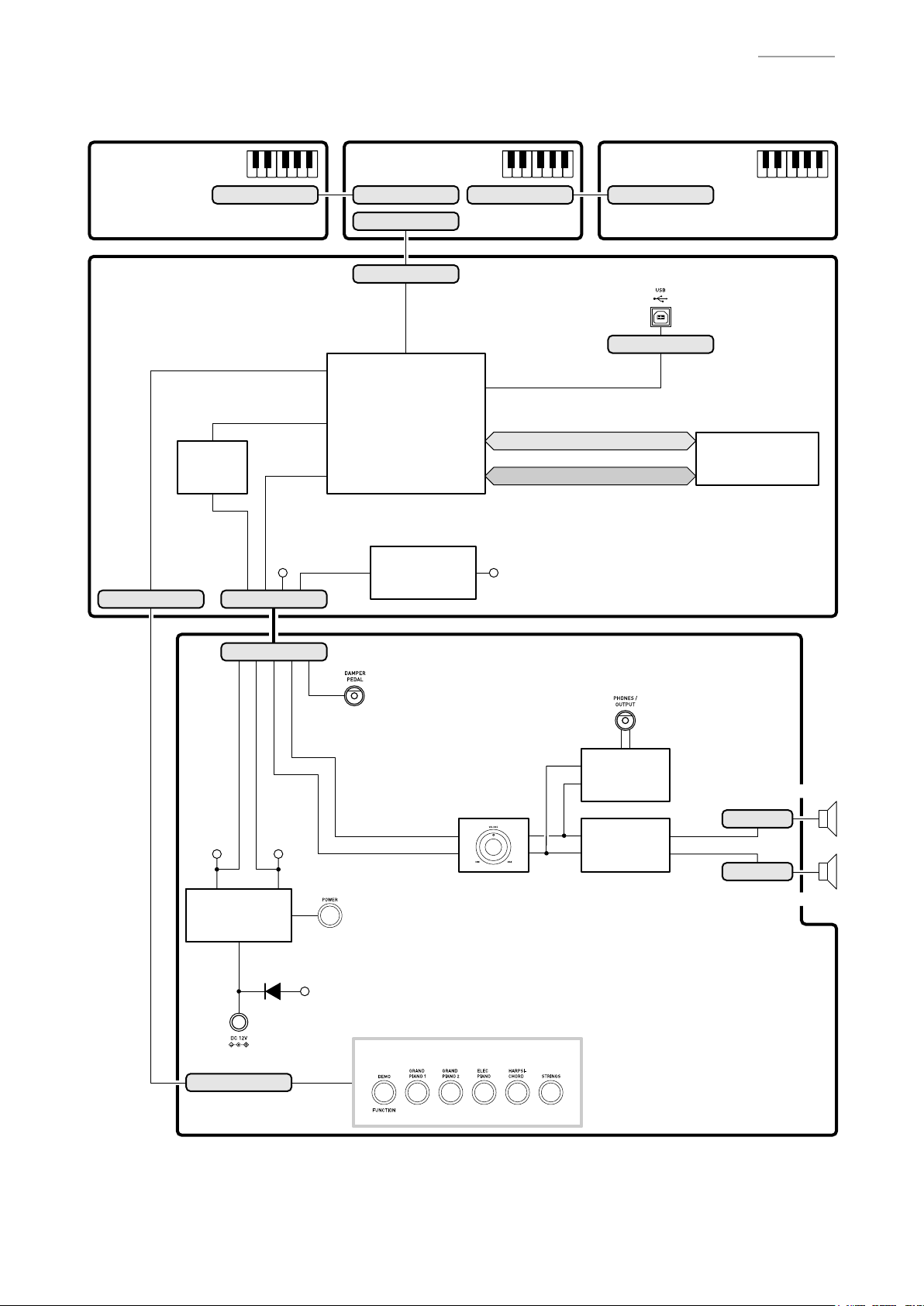
BLOCK AND WIRING DIAGRAM
CDP-120
KEYBOARD PCB
(M914-KYA1)
MAIN PCB
(M914-MDA1)
KI0~KI2, KC0, KC1
Filter
IC5
CN20 (5 pin)
CN801 (16 pin)
LOUT, ROUT
PEDAL,
APO, POFF,
MUTE, MIC IN
VA5
CN11 (11 pin)
KEYBOARD PCB
(M914-KYB1)
CN802 (16 pin) CN804 (16 pin) CN805 (16 pin)
CN803 (30 pin)
CN14 (30 pin)
FI0~FI10,
SI0~SI10,
KC0~KC7
MPU
IC7
Power Supply Circuit
VD5
IC6, C24, C25,
C27, C33, C35
VD3
KEYBOARD PCB
(M914-KYC1)
CN19 (4 pin)
MA1~MA22
MD0~MD15
USB
Flash Memory
(64 Mbit)
IC2
CN3 (11 pin)
VD5VA5
Power Supply Circuit
Power
IC3, Q4, D1,
Supply Circuit
C40~C45
IC3, Q4, D1
D2
DC 12 V (J3)
CN4 (5 pin)
PEDAL (J5)
POWER SWITCH
(SW1)
VCP
BUTTONS
MAIN VOL. (VR1)
LOUT
ROUT
POWER AMP PCB (M914-PSA1)
PHONES (J2)
Headphones
Amplifier
IC1
Power
Amplifier
IC2
SPEAKER (L)
CN1 (2 pin)
CN2 (2 pin)
SPEAKER (R)
– 2 –
Page 5
PCB INFORMATION
M914-MDA1M914-PSA1
M914-KYA1 M914-KYB1 M914-KYC1
Classifi cation Parts Name PCB Name Components
Main PCB PCB UNIT/MAIN M914-MDA1
Power Amp PCB PCB UNIT/PSA1 M914-PSA1
M914-KYA1
M914-KYC1
Keyboard PCB
PCB UNIT/KY and
RUBBER CONTACT
MPU, Flash Memory (64 Mbit),
Power Supply Circuit, Filter, USB Port
Power Supply Circuit, Power Ampli er
Headphones Ampli er, Power Switch,
Main Volume, DC 12 V Terminal,
DAMPER PEDAL Jack,
PHONES/OUTPUT Jack, Buttons
KeyboardM914-KYB1
CDP-120
– 3 –
Page 6
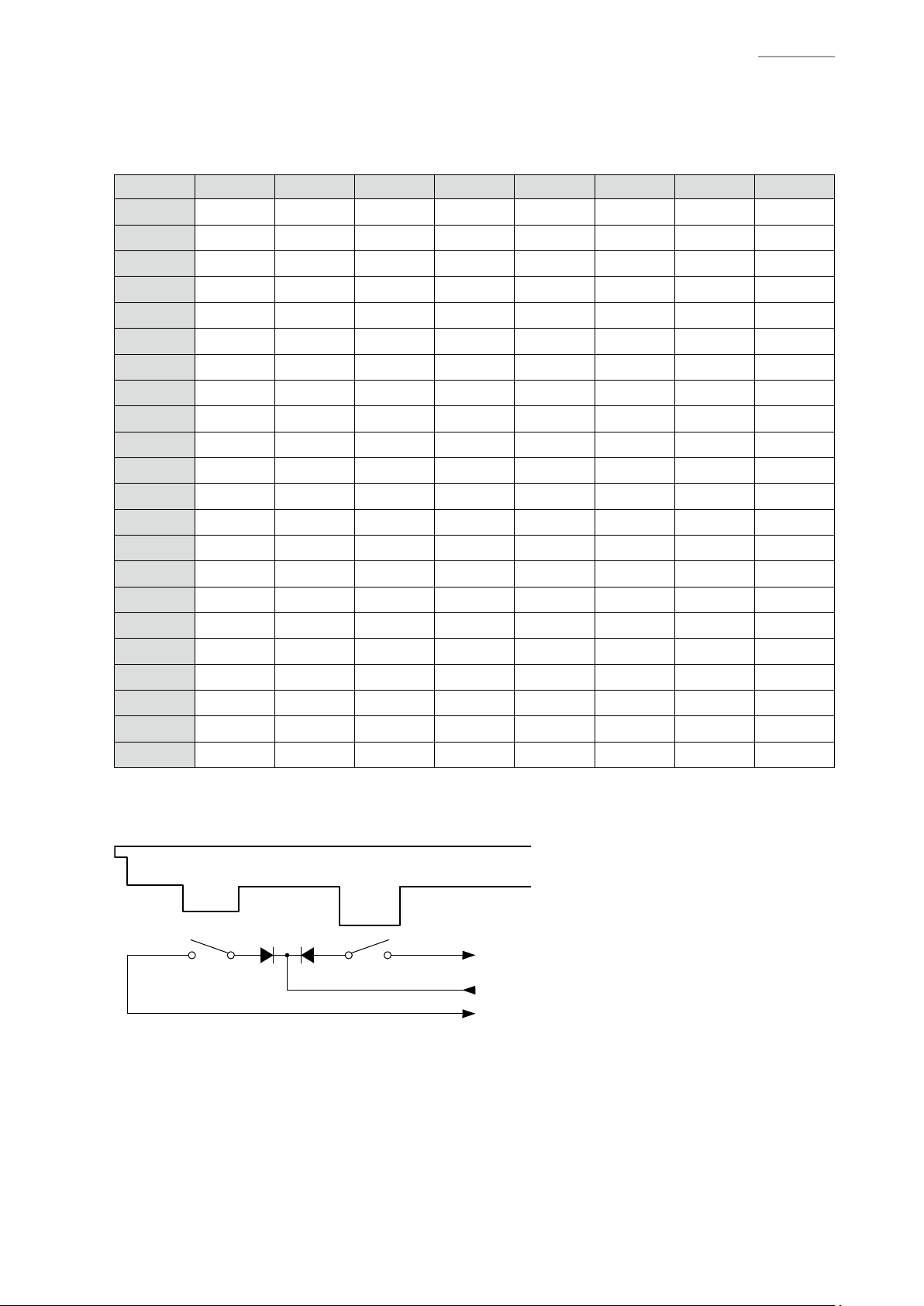
KEY MATRIX
KC0 KC1 KC2 KC3 KC4 KC5 KC6 KC7
FI0 A0
SI0 A0
FI1 F1
SI1 F1
FI2 C2#
SI2 C2#
FI3 A2
SI3 A2
FI4 F3
SI4 F3
FI5 C4#
SI5 C4#
FI6 A4
SI6 A4
FI7 F5
SI7 F5
FI8 C6#
SI8 C6#
FI9 A6
SI9 A6
FI10 F7
SI10 F7
1
2
1
2
1
2
1
2
1
2
1
2
1
2
1
2
1
2
1
2
1
2
CIRCUIT DESCRIPTION
A0#
A0#
F1#
F1#
D2
D2
A2#
A2#
F3#
F3#
D4
D4
A4#
A4#
F5#
F5#
D6
D6
A6#
A6#
F7#
F7#
1
2
1
2
1
2
1
2
1
2
1
2
1
2
1
2
1
2
1
2
1
2
B0
B0
G1
G1
D2#
D2#
B2
B2
G3
G3
D4#
D4#
B4
B4
G5
G5
D6#
D6#
B6
B6
G7
G7
1
2
1
2
1
2
1
2
1
2
1
2
1
2
1
2
1
2
1
2
1
2
C1
C1
G1#
G1#
E2
E2
C3
C3
G3#
G3#
E4
E4
C5
C5
G5#
G5#
E6
E6
C7
C7
G7#
G7#
1
2
1
2
1
2
1
2
1
2
1
2
1
2
1
2
1
2
1
2
1
2
C1#
C1#
A1
A1
F2
F2
C3#
C3#
A3
A3
F4
F4
C5#
C5#
A5
A5
F6
F6
C7#
C7#
A7
A7
1
2
1
2
1
2
1
2
1
2
1
2
1
2
1
2
1
2
1
2
1
2
D1
D1
A1#
A1#
F2#
F2#
D3
D3
A3#
A3#
F4#
F4#
D5
D5
A5#
A5#
F6#
F6#
D7
D7
A7#
A7#
1
2
1
2
1
2
1
2
1
2
1
2
1
2
1
2
1
2
1
2
1
2
D1#
D1#
B1
B1
G2
G2
D3#
D3#
B3
B3
G4
G4
D5#
D5#
B5
B5
G6
G6
D7#
D7#
B7
B7
1
2
1
2
1
2
1
2
1
2
1
2
1
2
1
2
1
2
1
2
1
2
CDP-120
E1
1
E1
2
C2
1
C2
2
G2#
1
G2#
2
E3
1
E3
2
C4
1
C4
2
G4#
1
G4#
2
E5
1
E5
2
C6
1
C6
2
G6#
1
G6#
2
E7
1
E7
2
C8
1
C8
2
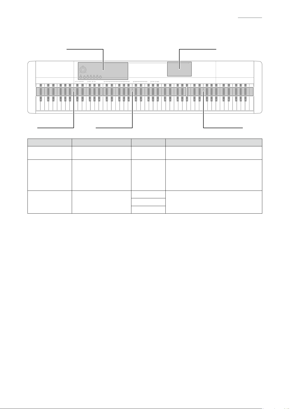
Each key has two contacts, the rst contact 1 and second contact 2.
NOTE: The diagram below illustrates how the contacts work.
Key
FI
Second contact
First contact
KC
SI
– 4 –
Page 7
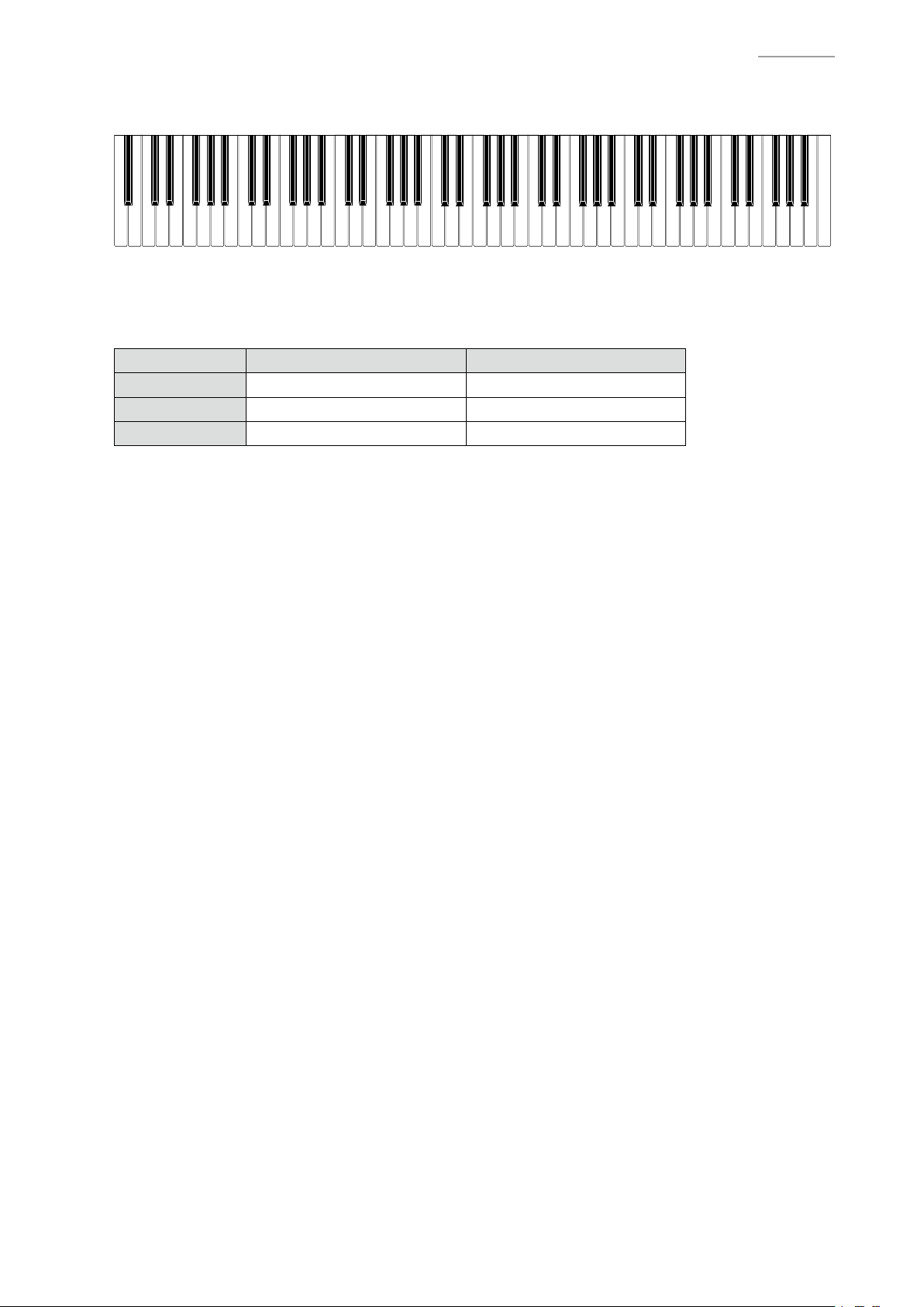
F#3G#3 A#3 C#4D#4 F#4G#4A#4 C#5D#5 F#5 G#5A#5
D#3
C#3A#2G#2F#2D#2C#2
A#1A#0 G#1F#1D#1C#1 A#6G#6F#6D#6C#6
A#7G#7F#7D#7C#7
NOMENCLATURE OF KEYS
CDP-120
C1 D1 E1 F1 G1 A1 B1A0 B0
BUTTON MATRIX
C2 D2 E2 F2 G2 A2 B2 C3 D3 E3
SWI3 STRINGS GRAND PIANO 2
SWI4 GRAND PIANO 1 HARPSICHORD
SWI5 DEMO, FUNCTION
F3 G3 A3 B3 C4 D4 E4 F4 G4 A4 B4 C5 D5 E5 F5 G5 A5 B5 C6
SWO0 SWO1
ELEC PIANO
B6A6G6F6E6D6 C7
B7A7G7F7E7D7 C8
– 5 –
Page 8
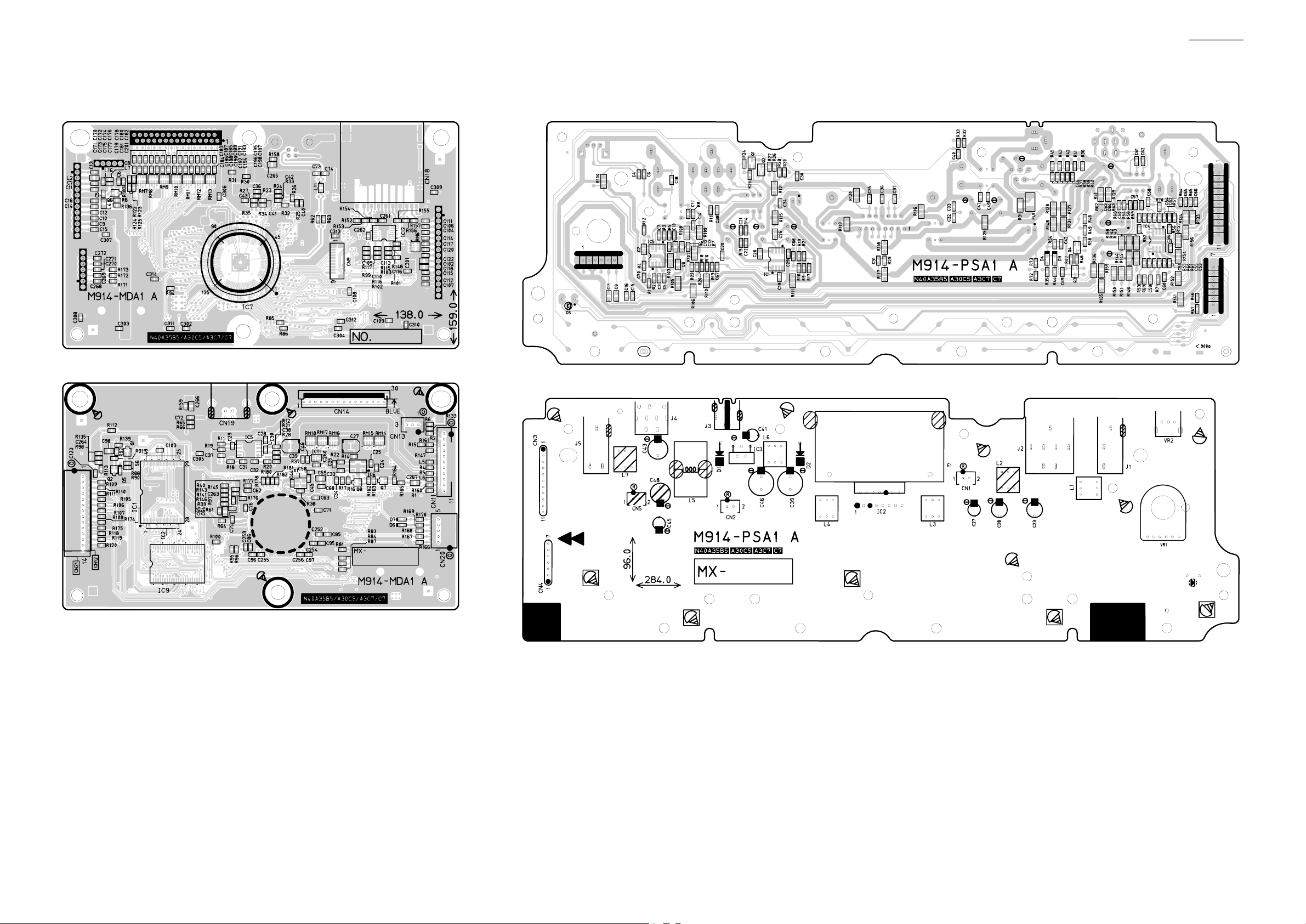
PRINTED CIRCUIT BOARDS
Main PCB: M914-MDA1 Power Amp PCB: M914-PSA1
CDP-120
– 6 –
Page 9
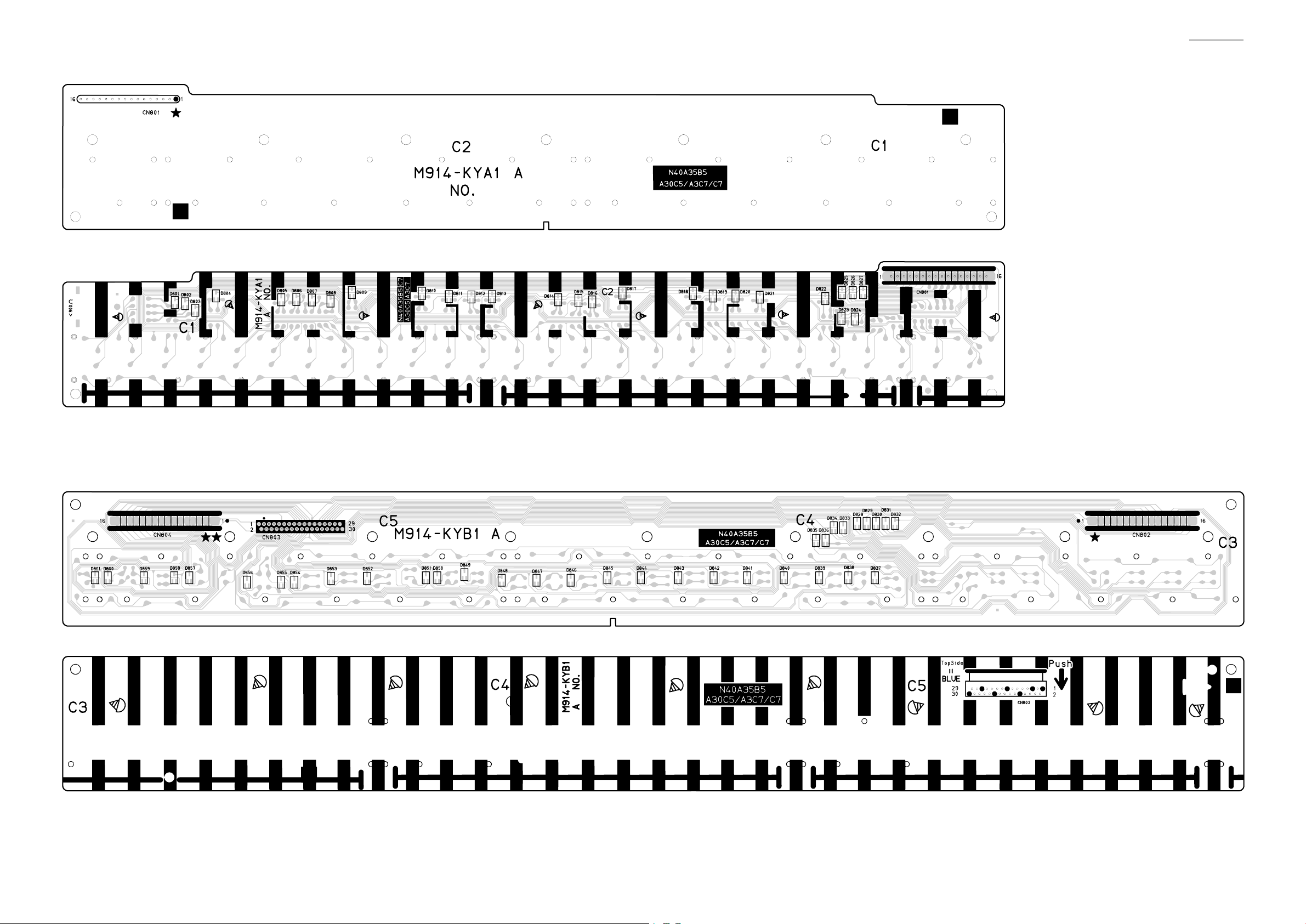
Keyboard PCB: M914-KYA1
CDP-120
Keyboard PCB: M914-KYB1
– 7 –
Page 10
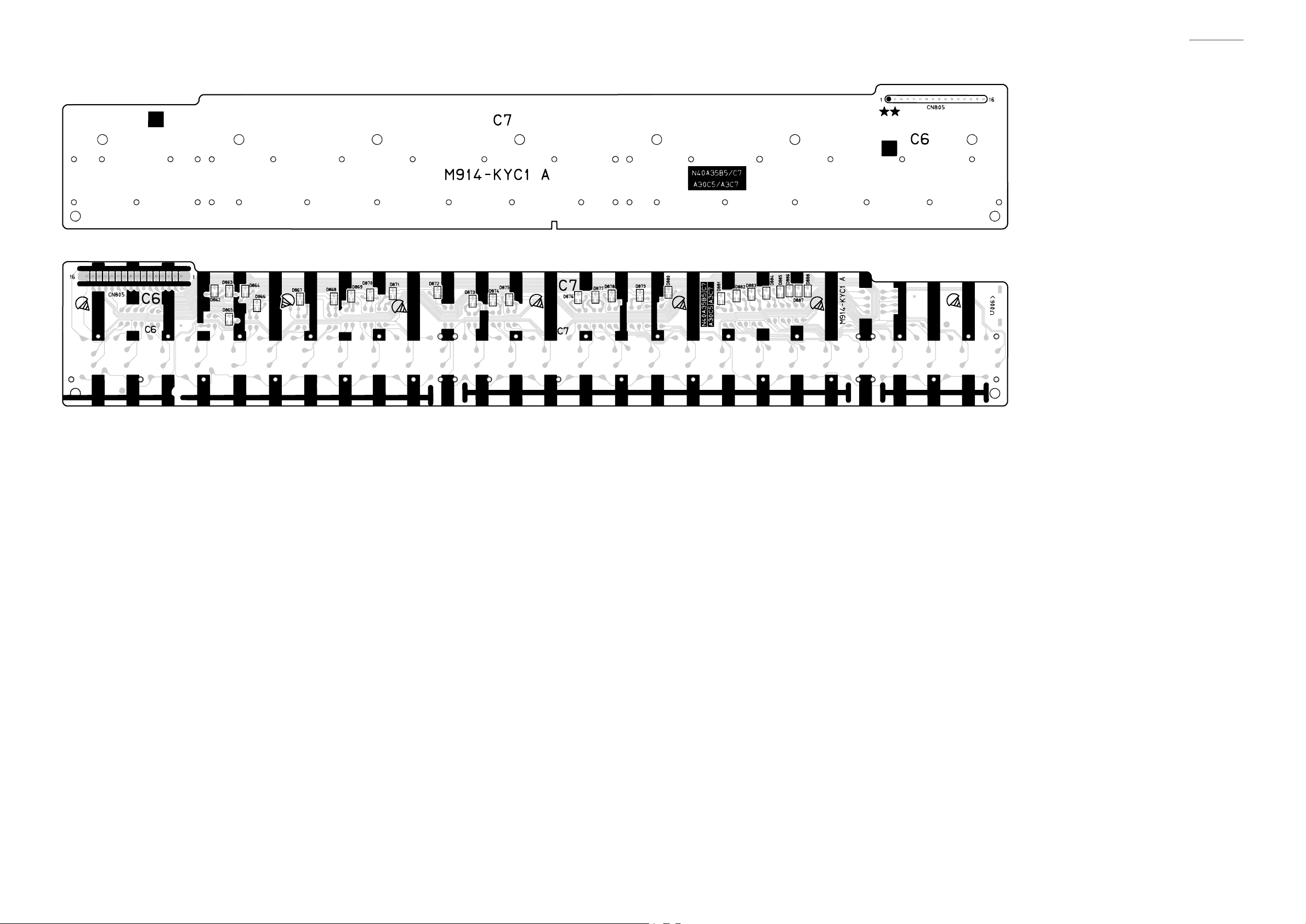
Keyboard PCB: M914-KYC1
CDP-120
– 8 –
Page 11
CDP-120
DISASSEMBLY
CAUTION
z
The photos show a prototype. The appearance of the instrument, such as color, may
differ from the actual model.
z
To avoid damages to the instrument and the oor, lay the instrument on a mattress
or blanket before starting disassembling.
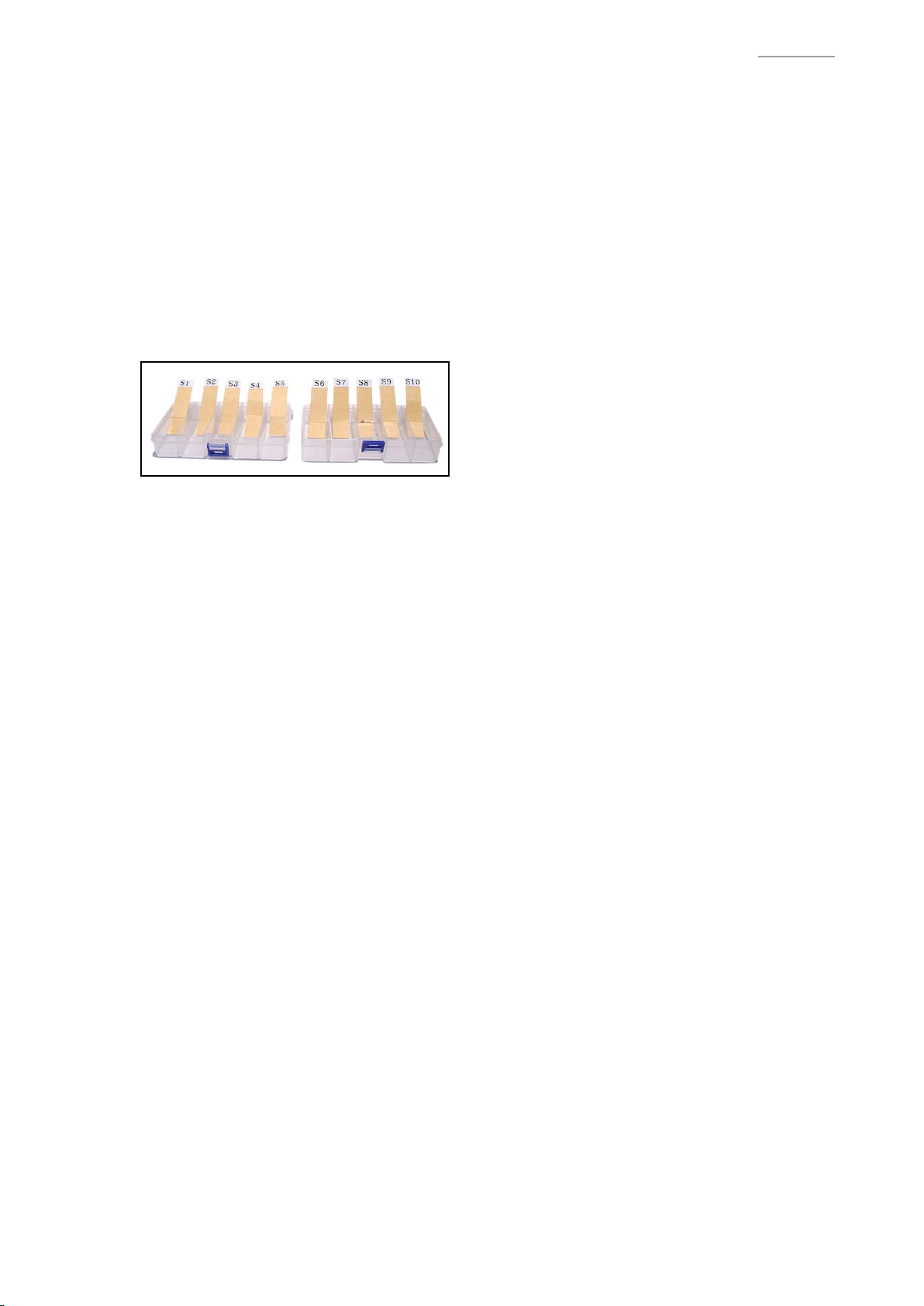
z
There are several kinds of screws. Be sure to use the correct type of screws when
reassembling. It is advisable to sort the screws as shown below after removing
them.
z
If a screw cap is attached to a screw, be sure to reattach the screw cap when
reassembling.
BEFORE STARTING REPAIR OR SERVICING
z
Remove the AC adaptor, AC cord or batteries.
z
Remove accessories such as the music stand.
– 9 –
Page 12
DISASSEMBLY
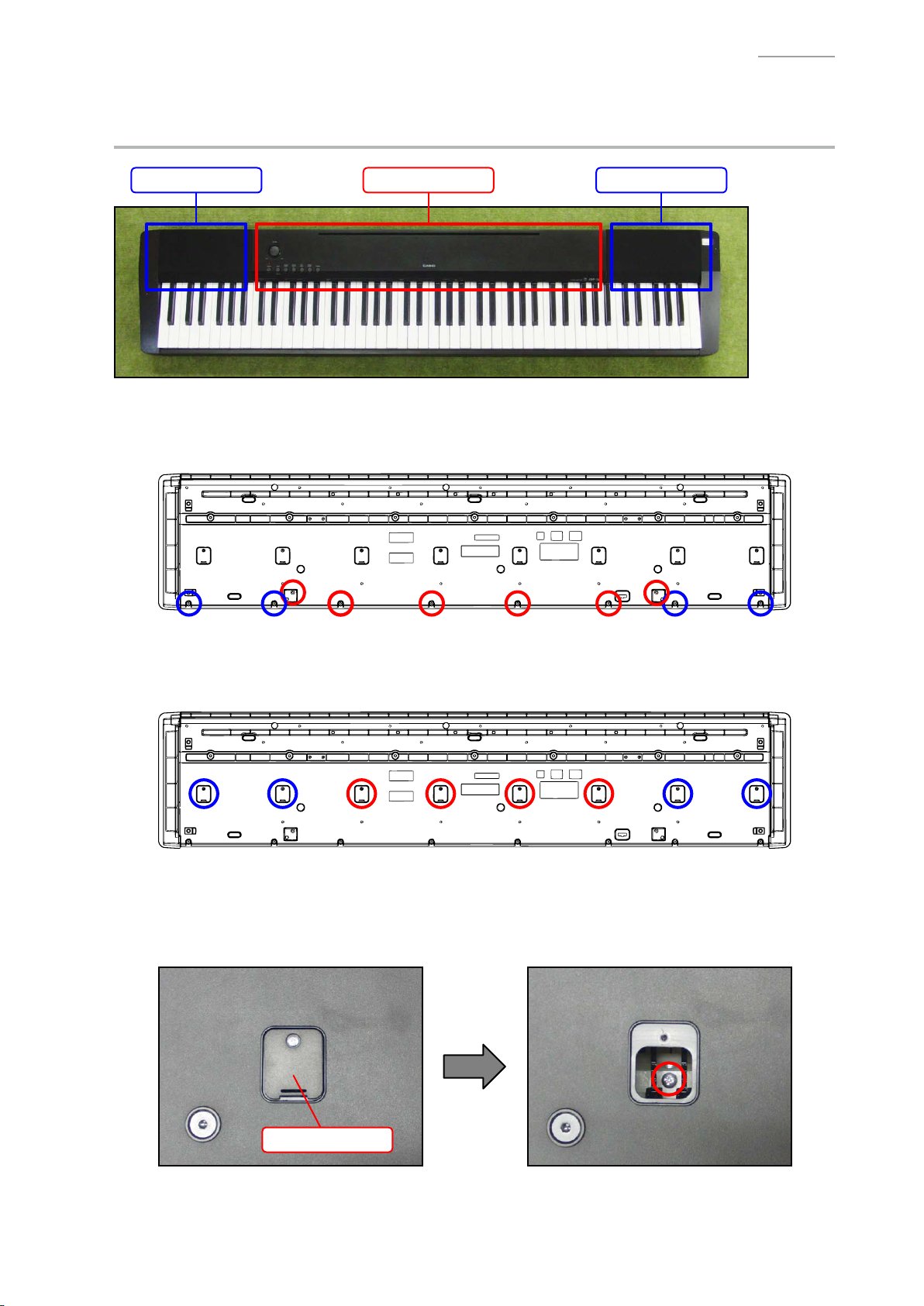
A. REMOVE THE PANEL UNITS
Main panel unit Right panel unitLeft panel unit
A-1. Undo 10 or six screws on the bottom surface of the main unit.
NOTE: To remove only the main panel unit, undo six screws indicated with red circles in the
illustration below.
CDP-120
A-2. Undo eight or four screws and then remove eight or four LOWER-COVERs.
NOTE: To remove only the main panel unit, undo four screws and remove the four LOWER-
COVERs indicated with red circles in the illustration below.
A-3. You will see a screw inside when you remove an LOWER-COVER. Undo and remove the screw
through each opening (eight or four screws in total).
NOTE: Do not drop the screws inside the main unit.
NOTE: Do not touch the hammer with the screwdriver while loosening the screws.
LOWER-COVER
– 10 –
Page 13

A-4. Place the main unit with the keys facing up.
A-5. Lift the main panel unit and turn it over.
NOTE: The main panel unit is connected to the lower case unit with the connectors and FFC.
Use caution when turn over the main panel unit.
A-6. Release the connector lock and remove the FFC.
A-7. Remove two connectors and then remove the main panel unit.
Main panel unit
CDP-120
Connector
(Left speaker)
Connector
(Right speaker)
FFC
(M914-KYB1)
– 11 –
Page 14

A-8. Undo three screws on the RIGHT-SIDE-CASE and then remove the RIGHT-SIDE-CASE.
RIGHT-SIDE-CASE
CDP-120
A-9. Undo three screws on the LEFT-SIDE-CASE and then remove the LEFT-SIDE-CASE.
LEFT-SIDE-CASE
– 12 –
Page 15

CDP-120
A-10. Undo two screws on the RIGHT-SIDE-INNER-CASE and then remove the right panel unit.
RIGHT-SIDE-INNER-CASE
Right panel unit
A-11. Undo two screws on the LEFT-SIDE-INNER-CASE and then remove the left panel unit.
LEFT-SIDE-INNER-CASE
Left panel unit
– 13 –
Page 16

B. REMOVE THE M914-MDA1 PCB (MAIN PCB)
B-1. Remove two connectors.
B-2. Undo four screws and then remove the M914-MDA1 PCB.
M914-MDA1 PCB Connectors (M914-PSA1)
C. REMOVE THE M914-PSA1 PCB (POWER AMP PCB)
C-1. Remove the ROTARY-KNOB
CDP-120
ROTARY-KNOB
C-2. Remove two connectors from the M914-MDA1 PCB.
M914-MDA1 PCB M914-PSA1 PCBConnectors (M914-PSA1)
C-3. Undo 11 screws and then remove the M914-PSA1 PCB and rubber key.
M914-PSA1 PCB
M914-PSA1 PCB
– 14 –
Page 17

D. REMOVE THE SPEAKER
D-1. Unsolder two lead wires.
D-2. Undo four screws and then remove the SPEAKER.
<Left speaker> <Right speaker>
CDP-120
Lead wire (Red)
Lead wire (Black)
E. REMOVE THE KY-ASSY
E-1. Undo three screws and then remove the LEFT-SIDE-INNER-CASE.
LEFT-SIDE-INNER-CASE
Lead wire (Black)
Lead wire (Red)
E-2. Undo three screws and then remove the RIGHT-SIDE-INNER-CASE.
RIGHT-SIDE-INNER-CASE
E-3. Undo 26 screws.
– 15 –
Page 18

E-4. Undo three screws and then remove the KY-ASSY.
LOWER-CASE-UNIT
CDP-120
KY-ASSY
– 16 –
Page 19

DISASSEMBLY OF THE KY-ASSY
A. REMOVE THE KEYS
<Removing the keys>
• To remove the keys, you will need two of the tools described below.
• Before removing a black key, you must rst remove both white keys on either side of the black
key.
• White keys may be removed with the same procedures as removing black keys.
<Tool>
The tool used in the photos in this section was converted from a gardening ID tag. The size and
shape of an ID tag accord to the dimensions below.
<Note on shaping an ID tag>
The thickness of the tool must be within 1.2~1.3 mm. If the tool is too thin, removing keys become
difcult. If the tool is too thick, it may damage the rib of the chassis.
CDP-120
<Tool dimensions>
Width:
15~20 mm
R=2.75 mm
7 mm
Thickness:
within 1.2~1.3 mm
Use this part to
remove the key.
– 17 –
Page 20

CDP-120
A-1. Insert the two tools between the rib of the chassis and a key.
A-2. When the tools are inserted to a certain depth, the key begins to be lifted and can then be
removed.
<Cross-section image>
Tool
Rib of the chassis
Tools
Chassis
Key
– 18 –
Page 21

<Installing the keys>
A code is indicated at the foot of each key.
Set securely into the chassis.
• Refer to the illustration below for the location of each white key.
• Be sure to install each key at its designated location.
• All black keys are the same. A black key may be installed at any correct black-key location.
C E G B D F A C E G B D F A C E G B D F A C E G B
SA
DB F A C E G B D F A C E G B D F A C E G B D F A
Install a black key before installing the white keys on either of its sides. Follow the same
procedures below to install a black or white key.
(1) Assemble a key to a hammer.
(2) Press the protrusion of the chassis rmly into the keyhole.
(3) Press the key to see if it moves properly.
CDP-120
SC
Assemble a key to a hammer.
– 19 –
Page 22

CDP-120
Tweezers
B. REMOVE THE HAMMERS
B-1. Place the chassis upside down so that the hammers are visible.
B-2. Press the chassis with the tip of tweezers.
B-3. While catching a hammer with tweezers, set the tweezers against the resin part of the chassis.
B-4. Using the chassis-tweezer contact as a fulcrum point, press down against the resin part in the
direction of the red arrow in the illustration below, and then disengage the hammer.
NOTE: You must press the resin part of the hammer.
NOTE: Pressing on the metal part of the hammer may damage the area connected to the resin.
Press down the resin part.
Fulcrum point
– 20 –
Page 23

<Kinds of hammers>
Type of Hammer (for a white key)
<Hammers for black keys>
There are several kinds of hammers. The type of a hammer may be identied by the code
engraved on it.
Hammer Code (for a white key)
Type of Hammer (for a black key)
CDP-120
Hammer Code (for a black key)
Type of Hammer: “W” for a white key, “B” for a black key.
Hammer Code: The hammers for white keys are coded W1, W2, W3, and W4.
The hammers for black keys are coded B1, B2, B3, and W4.
<Location to install the hammer>
A hammer must be installed at the correct location according to its type. The combination of
hammers and keys are shown below.
B1 (9 keys) B2 (9 keys) B3 (9 keys) B4 (9 keys)
W1 (13 keys)
W2 (13 keys) W3 (13 keys) W4 (13 keys)
<Hammers for white keys>
– 21 –
Page 24

CDP-120
Tweezers
<Installing the hammers>
Be sure to install each hammer at its designated location. If a hammer does not move smoothly,
check if it is installed at the correct location.
Follow the same procedures shown below to install a hammer for both black and white keys.
Use the tweezers to set a hammer at its correct location.
(1)
(2)
Press the chassis with the tip of tweezers.
(3) Using the chassis-tweezers contact as a fulcrum point, press down the metal part of the
hammer in the direction of the red arrow in the illustration below, and then install the
hammer.
NOTE:
When installing, do not damage the felt.
Press down against the metal part.
Locked at this point
Fulcrum point
Be careful not to damage the felt.
– 22 –
Page 25

C. REMOVE THE M914-KYA1/KYB1/KYC1 PCBs (KEYBOARD PCB)
C-1. Release the connector lock and remove the FFC.
C-2. Remove 23 screws and then remove the M914-KYA1/KYB1/KYC1 PCBs.
FFC
M914-KYA1 PCB M914-KYB1 PCB M914-KYC1 PCB
CDP-120
C-3. Remove eight rubber contact strips.
NOTE: One rubber contact strip is shorter than the others.
Rubber contact strips
Rubber contact strips
Short rubber contact strip
Short rubber contact strip
– 23 –
Page 26

<Installing the keyboard PCB (M914-KYA1/KYB1/KYC1)>
(1) Connect the FFC to the M914-KYB1 PCB and lock the connector.
NOTE: Insert it rmly and lock up.
FFC
(2) Secure the M914-KYA1/KYB1/KYC1 PCBs with 23 screws.
Press the PCBs lightly in the direction of the red arrow in the illustration below while
tightening a screw.
CDP-120
(3) Install eight rubber contact strips.
NOTE: Be sure to install the short rubber contact strip at the correct location.
NOTE: Lightly insert the tip of a rubber contact strip into the PCB rst, and then, press it
in using the end of a paper clip. Do not press the rubber contact strip forcefully to
avoid damaging the rubber contact strip.
– 24 –
Page 27

DIAGNOSTIC PROGRAM
PREPARATION
(1) Connect the AC adaptor.
(2) Connect the pedal (SP-3 or SP-20) to the DAMPER PEDAL jack.
NOTE: SP-3 is the pedal unit that comes with CDP-120. SP-20 pedal is sold separately.
NOTE: “PEDAL CHECK” cannot be performed unless the pedal is connected.
(3) Turn the main volume to the maximum.
(4) Have a PC and a USB cable ready.
NOTE: “USB CHECK” cannot be performed without a PC and a USB cable.
Operating System: Windows® XP (SP2 or later) *1
Windows Vista® *2
Windows 7® *3
Mac OS® X (10.3.9, 10.4.11, 10.5.8 or later, 10.6.6 or later)
*1: Windows XP Home Edition/Windows XP Professional (32 bit)
*2: Windows Vista (32 bit)
*3: Windows 7 (32 bit, 64 bit)
CDP-120
HOW TO START THE DIAGNOSTIC PROGRAM
(1) Hold down the “FUNCTION”, “GRAND PIANO 2” and “HARPSICHORD” buttons at the same time,
to turn the power ON.
NOTE: Be sure to turn OFF the power when the test is nished.
(2) Release the “FUNCTION”, “GRAND PIANO 2” and “HARPSICHORD” buttons
(3) The diagnostic program starts and then CDP-120 enters in the root mode where it waits for test item
selection.
TEST ITEMS
In root mode, you can perform arbitrary test by pressing a desired button that corresponds to the test item.
Test Items Buttons Note
A. BUTTON CHECK FUNCTION
B. ROM VERSION CHECK HARPSICHORD
C. ROM CHECKSUM TEST GRAND PIANO 2
D. PEDAL CHECK ELEC PIANO Pedal (SP-3 or SP-20)
E. USB CHECK PC, USB cable
– 25 –
Page 28

CDP-120
TEST PROCEDURES
A. BUTTON CHECK
A-1. Press the “FUNCTION” button to perform the “BUTTON CHECK”.
A-2. Press the button in the order indicated in the illustration.
NOTE: You cannot cancel this check procedure mid-way.
<If the result passes>
The conrmation chord sounds.
<If the result fails>
If there is a button failure or the buttons are pressed in a wrong sequence, an error tone sounds.
A-3. When the “STRINGS” button is pressed at the end, press the “STRINGS” button again to return to
the root mode.
B. ROM VERSION CHECK
B-1. Press the “HARPSICHORD” button to perform the “ROM VERSION CHECK”.
B-2. Press the “A0” key.
<If the result passes>
The conrmation chord sounds.
<If the result fails>
The error tone sounds.
“A0” key
B-3. Press the “STRINGS” button to return to the root mode.
C. ROM CHECKSUM TEST
C-1. Press the “GRAND PIANO 2” button to select the “ROM CHECKSUM TEST”.
C-2. Press the “GRAND PIANO 2” button to perform the check.
<If the result passes>
The conrmation chord sounds.
<If the result fails>
The error tone sounds.
C-3. Press the “STRINGS” button to return to the root mode.
– 26 –
Page 29

CDP-120
D. PEDAL CHECK
D-1. Press the “ELEC PIANO” button to select the “PEDAL CHECK”.
D-2. Press the pedal.
<If the result passes>
The conrmation chord sounds.
<If the result fails>
The error tone sounds.
D-3. Press the “STRINGS” button to return to the root mode.
E. USB CHECK
NOTE: The following procedures are for a PC with Windows XP.
E-1. Connect the main unit to the PC with a USB cable.
E-2. Open the windows “Device Manager”, and then make sure “USB Audio Devices” is listed under
“Sound, video and game controllers”.
E-3. Disconnect the USB cable.
E-4. Verify “USB Audio Devices” is not listed under “Sound, video and game controllers”.
– 27 –
Page 30

35
CDP-120
EXPLODED VIEW
34
39
36
40
38
41
36
44
40
45
32
42
30
37
2
31
28
43
1
30
31
29
33
45
28
32
44
41
KEYBOARD UNIT
54
55
51
50
55
52
54
46
47
49
48
47
53
49
48
49
56
56
– 28 –
Page 31

CDP-120
KEYBOARD UNIT
6
10
13
11
12
17
7
18
19
14
15
16
20
4
8
21
9
5
3
23
22
24
25
26
27
23
24
25 22
– 29 –
Page 32

PARTS LIST
CDP-120
Notes:
1. Prices and specications are subject to change
without prior notice.
2. Refer to the latest “Parts Price Code” at
“PARTS FINDER” on the Casio Service WEB site
(https://www.servicecasio.com).
3. As for spare parts order and supply, refer to
the “GUIDEBOOK for Spare parts Supply”,
published separately.
4. The numbers in item column correspond to
the same numbers in drawing.
– 30 –
Page 33

1: CDP-120_BLACK_DI
2: CDP-120_BLACK_EU
3: CDP-120_BLACK_UK
4: CDP-120_BLACK_US
CDP-120
Specification R RemarksN Item Code No. Parts Name
MAIN PCB
N 1 10399371 PCB UNIT/MAIN TK-RJM511112*001 1111 AMDA1
CN19 10236624 CONNECTOR/USB UBR24-4K5G00 1111 C
D6,D7 10009218 DIODE 1SS400TE61 2222 X
IC5 10211950 IC NJM2068M-D(TE1) 1111 X
IC11 10137770 IC TC7S08FU(TE85L.F) 1111 X
N IC6 10398240 IC XC6402FV36PR-G 1111 X
N IC2 10396325 LSI/MEMORY MX29LV640EBTI-70G 1111 C
L11 10193074 COIL DLW21HN181SQ2L 1111 X
Q7,Q8 69300298 TRANSISTOR 2SC4081T106R 2222 X
X1 10375016 RESONATOR 7V48080006 1111 X
POWER AMP PCB
N 2 10399370 PCB UNIT/PSA1 TK-RJM511113*001 1111 BPSA1
N D1,D2 10260786 DIODE 1N5822-C144 2222 X
IC3 10375029 IC LA5756-MDB-E 1111 X
IC2 10306512 IC TDA7297 1111 X
J5 10206815 JACK/PEDAL JY-6314*01-030 1111 B
J2 10305218 JACK/PHONE JY-6316B*01-070 1111 B
J3 10334294 JACK/DC KM02022ABMP 1111 A
L2 10231919 COIL RB53-856396NP 1111 X
L3,L4,L6 10231920 COIL RB53-856397NP 3333 X
L5 10232457 COIL RII7-860400NP 1111 X
N VR1 10407265 VARIABLE RESISTOR F164KPD-1N-CASIO-4 1111 BMain volume
D3,D4 23901820 DIODE 1SS355TE-17 2222 X
IC1 10306415 IC BH3547F-E2 1111 X
Q4 69409403 TRANSISTOR 2SA1576AT106R 1111 X
Q1-Q3 69300298 TRANSISTOR 2SC4081T106R 3333 X
Q'ty
1234
Price
Code
KEYBOARD PCB
3 10399792 PCB UNIT/KY and RUBBER CONTACT TK-RJM511215*001 1111 CKYA1/KYB1/KYC1
N D801-D827 10398230 DIODE DAN202UMTL 27 27 27 27 X
N D828-D861 10398230 DIODE DAN202UMTL 34 34 34 34 X
N D862-D888 10398230 DIODE DAN202UMTL 27 27 27 27 X
4 10195879 RUBBER CONTACT/AG RJM502920-001V02 7777 A
5 10195880 RUBBER CONTACT/GC RJM502921-001V02 1111 B
KEYBOARD UNIT
6 10399791 KEYBOARD UNIT TK-RJM511279*001 1111 C
N 7 10363265 WHITE KEY/SA RJM502795-003V05 1111 X
N 8 10398222 WHITE KEY/B RJM502794-001V04 1111 A
N 9 10398223 WHITE KEY/CEGB RJM502862-001V04 7777 A
N 10 10398225 WHITE KEY/DFA RJM502863-001V04 7777 A
N 11 10363266 WHITE KEY/SC RJM502796-003V05 1111 X
N 12 10398220 BLACK KEY RJM502797-001V03 36 36 36 36 A
13 10341062 HAMMER UNIT/W1 TK-RJM509600*001 13 13 13 13 C
14 10341063 HAMMER UNIT/W2 TK-RJM509601*001 13 13 13 13 C
15 10341064 HAMMER UNIT/W3 TK-RJM509602*001 13 13 13 13 C
16 10341065 HAMMER UNIT/W4 TK-RJM509603*001 13 13 13 13 C
17 10341066 HAMMER UNIT/B1 TK-RJM509604*001 9999 C
18 10341067 HAMMER UNIT/B2 TK-RJM509605*001 9999 C
19 10341068 HAMMER UNIT/B3 TK-RJM509606*001 9999 C
20 10341069 HAMMER UNIT/B4 TK-RJM509607*001 9999 C
– 31 –
Page 34

1: CDP-120_BLACK_DI
2: CDP-120_BLACK_EU
3: CDP-120_BLACK_UK
4: CDP-120_BLACK_US
CDP-120
Specification R RemarksN Item Code No. Parts Name
21 10336108 CABLE UL2896-30-265-MACP 1111 X
N 22 10398226 FELT/LOWER LIMIT/BLACK KEY RJM510067-002V02 1111 X
N 23 10398227 FELT/LOWER LIMIT/WHITE KEY RJM503562-002V02 1111 X
N 24 10398219 FELT/UPPER LIMIT/HAMMER RJM511203-001V01 1111 X
25 10399793 FELT/LOWER LIMIT/HAMMER TK-RJM507910*001 1111 X
26 10388000 PLATE RJM510952-001V01 1111 X
27 10343387 FABRIC TAPE/ACP RJM510100-001V01 1111 X
28 10175757 PACKING/10X386 RJM504743-001V01 2222 X
29 10128574 PACKING RJM503241-001V01 1111 X
N 30 69307137 PACKING M440857-1 4444 X
N 31 10397766 KEYBOARD SEALING RJM511107-001V01 2222 X
32 10175758 PACKING/10X100 RJM504744-001V01 2222 X
33 69287160 SPONGE/50X180 M440961-1 1111 X
PANEL UNIT
N 34 10398589 CASE/PANEL RJM511090-001V01 1111 X
35 10269765 KNOB/ROTARY M341109-008V01 1111 C
N 36 10398202 BRACKET RJM511073-001V01 2222 X
N 37 10398204 RUBBER BUTTON/A RJM511075-001V01 1111 X
SIDE PANEL UNIT
N 38 10398236 CASE SUB UNIT/PANEL/LEFT RJM511005*001V01 1111 X
N 39 10398237 CASE SUB UNIT/PANEL/RIGHT RJM511006*001V01 1111 X
40 10130104 FABRIC TAPE/10X180 M440259-002V01 2222 X
41 10284878 SPEAKER C0612J01 2222 X
N 42 10164046 HARNESS EH-2P-43-M420 1111 X
43 10308814 HARNESS EH-2P-85-M810 1111 X
44 69320969 SPONGE/50X285 M441325-1 2222 X
N 45 10312787 SPONGE/50X115 RJM506431-002V01 2222 X
Q'ty
1234
Price
Code
MAIN CASE UNIT
46 10399794 CASE UNIT/LOWER TK-RJM510997*001 1111 X
47
10201510 BRACKET RJM505933-001V01 4 4 4 4 X
N 48 10359076 BRACKET RJM505932-001V02 2222 X
49 10133655 RUBBER FOOT RJM503180-001V01 5555 X
N 50 10398588 CASE/SIDE/LEFT RJM510999-002V01 1111 X
N 51 10398197 CASE/SIDE/RIGHT RJM511000-001V01 1111 X
N 52 10398216 CASE/SIDE/INNER/LEFT RJM511001-001V01 1111 X
N 53 10398217 CASE/SIDE/INNER/RIGHT RJM511002-001V01 1111 X
54 10179177 FABRIC TAPE/6X310 RJM505229-001V01 2222 X
55 69307162 PACKING M440967-1 2222 X
56 10337052 LOWER COVER RJM509409-001V01 8888 X
ACCESSORIES
- 10342718 MUSIC STAND RJM508666-001V04 1111 C
- 10133504 FOOT PEDAL/SP3 TK-RJM503195*001 1111 X
- 10392266 AC ADAPTOR AD-A12150LW-F3 1111 Bwithout AC CORD
- 10361066 AC CORD UC2LT-M006A 1 1 X for US
- 10361067 AC CORD EC2LT-M002A 1 1 X for EU
- 10361068 AC CORD KC2LT-M002A 1 X for Korea
- 10361069 AC CORD AUC2LT-M002A 1 X for Australia
- 10361070 AC CORD BC2LT-M002A 1 X for UK
– 32 –
Page 35

Main PCB: M914-MDA1
(to PSA1/CN3)
CDP-120
SCHEMATIC DIAGRAMS
USB
Not used
(to PSA1/CN4)
(to KYB1/CN803)
– 33 –
Page 36

Power Amp PCB: M914-PSA1
(to MDA1/CN11)
DC 12 V IN (J3) PEDAL (J5)
CDP-120
PHONES (J2)
MAIN VOL. (VR1)
(to LEFT SPEAKER)
(to RIGHT SPEAKER)
POWER SWITCH
(SW1)
LEFT SPEAKER RIGHT SPEAKER
(to MDA1/CN20)
– 34 –
Page 37

Keyboard PCB: M914-KYA1
(to KYB1/CN802)
CDP-120
– 35 –
Page 38

Keyboard PCB: M914-KYB1
(to KYA1/CN801) (to MDA1/CN14) (to KYC1/CN805)
CDP-120
– 36 –
Page 39

Keyboard PCB: M914-KYC1
(to KYB1/CN804)
CDP-120
– 37 –
Page 40

Ver. 1 : Dec. 2012
• Correction of the EXPLODED VIEW (P28)
• Correction of the PARTS LIST (P32)
CASIO COMPUTER CO.,LTD.
Overseas Service Division
6-2, Hon-machi 1-Chome
Shibuya-ku, Tokyo 151-8543, Japan
 Loading...