

Page 1
AP-700
SEP. 2015
Ver. 2 : Mar. 2016
Page 2

AP-700
CONTENTS
SPECIFICATIONS . . . . . . . . . . . . . . . . . . . . . . . . . . . . . . . . . . . . . . . . . . . . . 1
BLOCK AND WIRING DIAGRAM . . . . . . . . . . . . . . . . . . . . . . . . . . . . . . . . . 3
CIRCUIT DESCRIPTION . . . . . . . . . . . . . . . . . . . . . . . . . . . . . . . . . . . . . . . . 4
PRINTED CIRCUIT BOARDS . . . . . . . . . . . . . . . . . . . . . . . . . . . . . . . . . . . . 7
DISASSEMBLY . . . . . . . . . . . . . . . . . . . . . . . . . . . . . . . . . . . . . . . . . . . . . . .11
DIAGNOSTIC PROGRAM . . . . . . . . . . . . . . . . . . . . . . . . . . . . . . . . . . . . . . 55
EXPLODED VIEW . . . . . . . . . . . . . . . . . . . . . . . . . . . . . . . . . . . . . . . . . . . . 67
PARTS LIST. . . . . . . . . . . . . . . . . . . . . . . . . . . . . . . . . . . . . . . . . . . . . . . . . 72
SCHEMATIC DIAGRAMS . . . . . . . . . . . . . . . . . . . . . . . . . . . . . . . . . . . . . . 79
Page 3
AP-700
SPECIFICATIONS
Keyboard 88-key piano keyboard
• Layer, Split
• Duet: Adjustable tone range (–2 to +2 octaves)
• Transpose: 2 octaves (–12 to 0 to +12)
• Octave shift: 4 octaves (–2 to 0 to +2)
Sound Source • Number of Tones: 26
• Maximum polyphony: 256 tones
• Touch Response (3 sensitivity levels, Off)
• Tuning: 415.5 Hz to 440.0 Hz to 465.9 Hz (0.1 Hz units)
• Temperament: Equal temperaments plus 16 other types
• Stretch Tuning: 5 types, Off, Auto Setting
Acoustic Simulator Damper Resonance, Damper noise, Hammer response,
String resonance, Lid simulator
Effects Brilliance (–3 to 0 to 3), Hall simulator (6 types), Chorus (4 types),
DSP, Headphone mode, Volume sync equalizer (3 types, Off)
Concert Play • Number of Songs: 15
• Playback of Concert Play songs obtained with a computer, etc.
• Song volume: Adjustable
• Playback at 80 % of normal tempo
• 2 Modes: LISTEN, PLAY
Music Library • Number of Songs: 60, User Songs: 10 (Up to approximately 90
KB per song, approximately 900 KB for 10 songs)*
* Based on 1 KB = 1024 bytes, 1 MB = 1024
• Song volume: Adjustable
• Part On/Off: L, R
Grand Piano Demo Song 6
MIDI Recorder • Functions: Real-time recording, playback
• Number of Song: 1
• Number of Tracks: 2
• Capacity: Approximately 5,000 notes total
• Recorded Data Protection: Built-in fl ash memory
• MIDI Recorder Volume Level: Adjustable
Audio Recorder • Real-time recording and playback to USB fl ash drive*
* Linear PCM, 16bit, 44.1 kHz, stereo .WAV format
• Songs: 99 fi les
• Approximately 25 minutes maximum recording per fi le.
• Audio Recorder Volume Level: Adjustable
2
bytes
Metronome • Beats: 0 to 9
• Tempo Range: 20 to 255
• Metronome Volume Level: Adjustable
Pedals Damper (with half-pedal operation), Soft, Sostenuto
– 1 –
Page 4
Other Functions • Setting backup
• Operation Lock
MIDI 16-channel multi-timbre receive
USB Flash Drive • Capacity: 32 GB or less recommended
• SMF direct playback, data storage, data loading,
USB fl ash drive format, audio data playback and storage
Inputs/Outputs • PHONES jacks: Stereo standard jacks × 2
• Power: 24 V DC
• MIDI OUT/IN terminals
• LINE IN R, L/MONO jacks: Standard jacks × 2
Input impedance: 9.0 KΩ
Input voltage: 200 mV
• LINE OUT R, L/MONO jacks: Standard jacks × 2
Output impedance: 2.3 KΩ
Output voltage: 1.8 V (RMS) MAX
• USB port: Type B
• USB fl ash drive port: Type A
• Pedal connector
AP-700
Speakers
φ
12 cm × 4 + φ5 cm × 2 (Output 30 W + 30 W)
Power Requirements AC Adaptor: AD-E24500LW
• Auto Power Off: Approximately 4 hours after last operation. Auto
Power Off can be disabled.
Power Consumption 24 V = 28 W
Dimensions Digital Piano and Stand:
137.7 (W) × 42.7 (D) × 91.1 (H) cm (54
1
/4 × 16
13
/16
× 35 7/8 inch)
Weight Digital Piano and Stand: approximately 48.0 kg (105.8 lbs)
– 2 –
Page 5
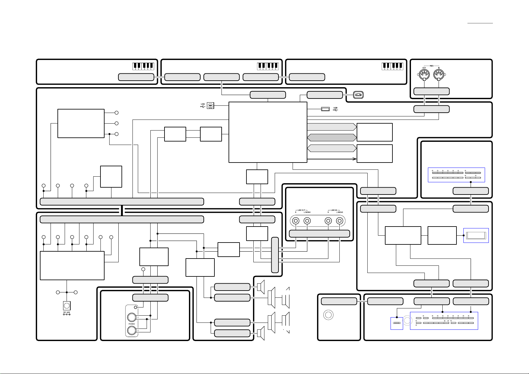
BLOCK AND WIRING DIAGRAM
KEYBOARD PCB (M920-KYA1) KEYBOARD PCB (M920-KYB1) KEYBOARD PCB (M920-KYC1)
MAIN PCB (M936-MDA1)
Power Supply Circuit
IC3, IC4, IC10,
C144~C149,
C152~154, C158
Schmitt
VD5 VA12 VA5 VDP3
VD5 VA12 VA5 VDP3 VH5 VA3
Power Supply Circuit
IC1, IC2, IC5~IC7, C55, C56,
C58~C63, C65~C69,
C122, C123, C185, D6, D7
VC PVCC
DC (J1)
Trigger
IC7
CN16 (13 pin)
CN10 (13 pin)
APO
POWER
PHONES
POWER AMP PCB
(M936-PSA1)
CN801 (17 pin)
VD18
VD1
VD3
APO
LAMP
(J702)
(J701)
CN802 (17 pin)
KI0~KI21, KS0~KS2, KB0~KB3
USB (CN13)
HPDT, HPMUTE, SPMUTE
Filter
IC14
LR
Headphones
Amplifier
IC8
VD5
CN7 (7 pin)
CN701 (7 pin)
PHONES PCB
(M920-HPA1)
L
R
Power
Amplifier
IC4
CN803 (30 pin)
DAC
IC6
Filter
IC16
CN5 (2 pin)
CN4 (2 pin)
CN3 (2 pin)
CN2 (2 pin)
CN804 (17 pin)
CN3 (30 pin)
MPU
IC9
ADC
IC5
LR
CN24 (5 pin)
CN13 (5 pin)
Filter
IC10
TWEETER (R)
TWEETER (L)
CN805 (17 pin)
CN8 (5 pin)
Control Signal
LINE PCB (M921-JKA1)
LINE OUT R (J506), L/MONO (J505)
LINE IN R (J504), L/MONO (J503)
CN502 (5 pin)
CN14 (5 pin)
SPEAKERS (R)
CN605 (3 pin)
SPEAKERS (L)
CONSOLE PCB
(M921-CNA3)
USB (CN12)
DA0~DA13
DQ0~DQ15
RD0~RD7
VOLUME
(VR602)
PEDAL
CONNECTOR
DDR2 SDRAM
IC8
EEPROM
IC2
RSTB, SIN1,
SOUT1, VOLPWSW
CN25 (9 pin)
CN3 (9 pin)
PWSW, VOL
KC0~KC4, LEC0~LEC2,
KI4~KI7, LES6~LES10
Button/LED/LCD
Controller
IC1
LES0~LES5, KC0~KC4
LEC0~LEC2, KI0~KI3
LCD PCB
(M921-LCA1)
CN603 (11 pin)CN604 (3 pin)
SW600
SW600
CONSOLE PCB (M921-CNA1)
CN301 (4 pin)
CN5 (4 pin)
CONSOLE PCB
(M921-CNA2)
SW621~SW638SW621~SW638
LCD Driver
IC2
CN4 (11 pin)
AP-700
MIDI (CN302)
MIDI PCB
(M921-CNA4)
CN602 (17 pin)
CN2 (17 pin)
LCD
CN1 (11 pin)
CN601 (11 pin)
SW601~SW620
SW601~SW620
– 3 –
Page 6
AP-700
CIRCUIT DESCRIPTION
Y
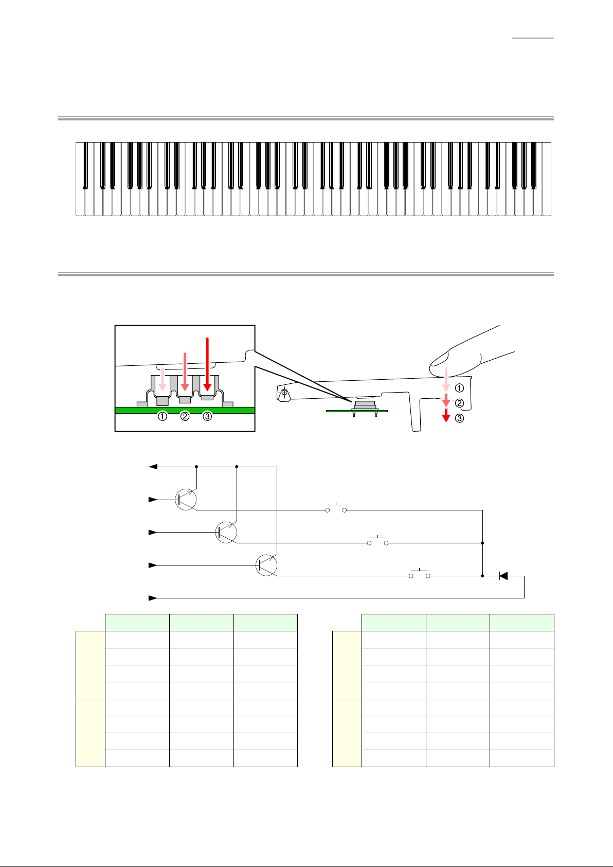
Nomenclature of Keys
A0# C1# D1# F1# G1# A1# C2# D2# F2# G2# A2# C3# D3# F3# G3# A3# C4# D4# F4# G4# A4# C5# D5# F5# G5# A5# C6# D6# F6# G6# A6# C7# D7# F7# G7# A7#
A0 B0 C1 D1 E1 F1 G1 A1 B1 C2 D2 E2 F2 G2 A2 B2 C3 D3 E3 F3 G3 A3 B3 C4 D4 E4 F4 G4 A4 B4 C5 D5 E5 F5 G5 A5 B5 C6 D6 E6 F6 G6 A6 B6 C7 D7 E7 F7 G7 A7 B7 C8
Y
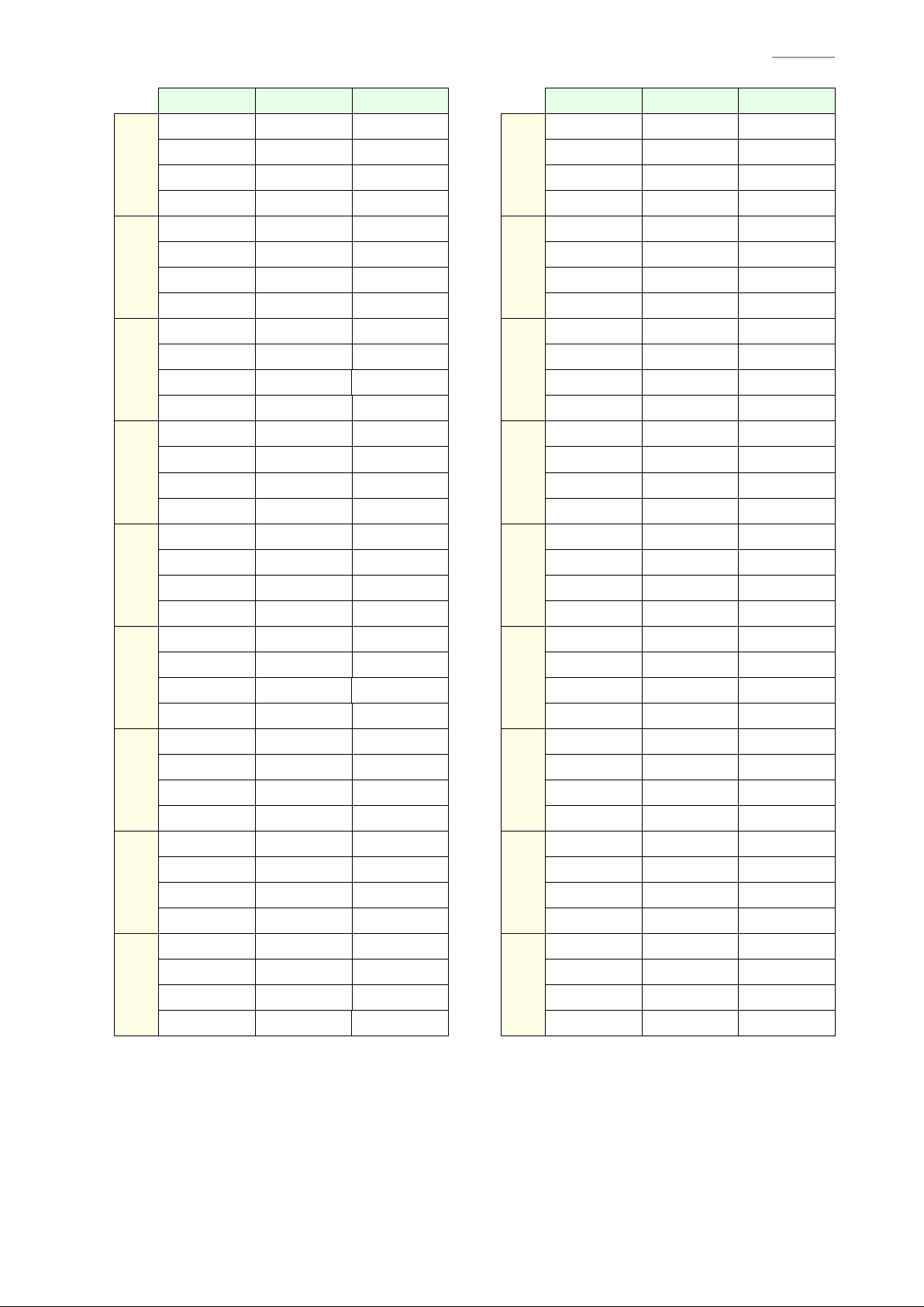
Key Matrix
Each key has three contacts, the fi rst contact , second contact and third contact .
[NOTE] The diagram below illustrates how the contacts work.
KI0
KI1
KB (0-3)
KS0
KS1
KS2
First contact
Second contact
Third contact
KI (0-21)
KS0 KS1 KS2 KS0 KS1 KS2
A0
A0#
B0
C1
C1#
D1
D1#
E1
(KB0) A0
(KB1) A0#
(KB2) B0
(KB3) C1
(KB0) C1#
(KB1) D1
(KB2) D1#
(KB3) E1
(KB0) A0
(KB1) A0#
(KB2) B0
(KB3) C1
(KB0) C1#
(KB1) D1
(KB2) D1#
(KB3) E1
(KB0)
(KB1) F4#
(KB2) G4
(KB3) G4#
(KB0)
(KB1) A4#
(KB2) B4
(KB3) C5
KI11
KI12
F4
(KB0) F4
(KB1) F4#
(KB2) G4
(KB3) G4#
A4
(KB0) A4
(KB1) A4#
(KB2) B4
(KB3) C5
(KB0) F4
(KB1) F4#
(KB2) G4
(KB3) G4#
(KB0) A4
(KB1) A4#
(KB2) B4
(KB3) C5
(KB0)
(KB1)
(KB2)
(KB3)
(KB0)
(KB1)
(KB2)
(KB3)
– 4 –
Page 7
KI2
KI3
KI4
KI5
KI6
KI7
KI8
KI9
KI10
KS0 KS1 KS2 KS0 KS1 KS2
F1
F1#
G1
G1#
A1
A1#
B1
C2
C2#
D2
D2#
E2
F2
F2#
G2
G2#
A2
A2#
B2
C3
C3#
D3
D3#
E3
F3
F3#
G3
G3#
A3
A3#
B3
C4
C4#
D4
D4#
E4
(KB0) F1
(KB1) F1#
(KB2) G1
(KB3) G1#
(KB0) A1
(KB1) A1#
(KB2) B1
(KB3) C2
(KB0) C2#
(KB1) D2
(KB2) D2#
(KB3) E2
(KB0) F2
(KB1) F2#
(KB2) G2
(KB3) G2#
(KB0) A2
(KB1) A2#
(KB2) B2
(KB3) C3
(KB0) C3#
(KB1) D3
(KB2) D3#
(KB3) E3
(KB0) F3
(KB1) F3#
(KB2) G3
(KB3) G3#
(KB0) A3
(KB1) A3#
(KB2) B3
(KB3) C4
(KB0) C4#
(KB1) D4
(KB2) D4#
(KB3) E4
(KB0)
(KB1) D5
(KB2) D5#
(KB3) E5
(KB0)
(KB1) F5#
(KB2) G5
(KB3) G5#
(KB0)
(KB1) A5#
(KB2) B5
(KB3) C6
(KB0)
(KB1) D6
(KB2) D6#
(KB3) E6
(KB0)
(KB1) F6#
(KB2) G6
(KB3) G6#
(KB0)
(KB1) A6#
(KB2) B6
(KB3) C7
(KB0)
(KB1) D7
(KB2) D7#
(KB3) E7
(KB0)
(KB1) F7#
(KB2) G7
(KB3) G7#
(KB0)
(KB1) A7#
(KB2) B7
(KB3) C8
KI13
KI14
KI15
KI16
KI17
KI18
KI19
KI20
KI21
C5#
(KB1) D5
(KB3) E5
F5
(KB0) F5
(KB2) G5
A5
(KB0) A5
(KB2) B5
(KB3) C6
C6#
(KB1) D6
(KB3) E6
F6
(KB0) F6
(KB2) G6
A6
(KB0) A6
(KB2) B6
(KB3) C7
C7#
(KB1) D7
(KB3) E7
F7
(KB0) F7
(KB2) G7
A7
(KB0) A7
(KB2) B7
(KB3) C8
(KB0) C5#
(KB2) D5#
(KB1) F5#
(KB3) G5#
(KB1) A5#
(KB0) C6#
(KB2) D6#
(KB1) F6#
(KB3) G6#
(KB1) A6#
(KB0) C7#
(KB2) D7#
(KB1) F7#
(KB3) G7#
(KB1) A7#
(KB0) C5#
(KB1) D5
(KB2) D5#
(KB3) E5
(KB0) F5
(KB1) F5#
(KB2) G5
(KB3) G5#
(KB0) A5
(KB1) A5#
(KB2) B5
(KB3) C6
(KB0) C6#
(KB1) D6
(KB2) D6#
(KB3) E6
(KB0) F6
(KB1) F6#
(KB2) G6
(KB3) G6#
(KB0) A6
(KB1) A6#
(KB2) B6
(KB3) C7
(KB0) C7#
(KB1) D7
(KB2) D7#
(KB3) E7
(KB0) F7
(KB1) F7#
(KB2) G7
(KB3) G7#
(KB0) A7
(KB1) A7#
(KB2) B7
(KB3) C8
AP-700
(KB0)
(KB1)
(KB2)
(KB3)
(KB0)
(KB1)
(KB2)
(KB3)
(KB0)
(KB1)
(KB2)
(KB3)
(KB0)
(KB1)
(KB2)
(KB3)
(KB0)
(KB1)
(KB2)
(KB3)
(KB0)
(KB1)
(KB2)
(KB3)
(KB0)
(KB1)
(KB2)
(KB3)
(KB0)
(KB1)
(KB2)
(KB3)
(KB0)
(KB1)
(KB2)
(KB3)
– 5 –
Page 8
Y
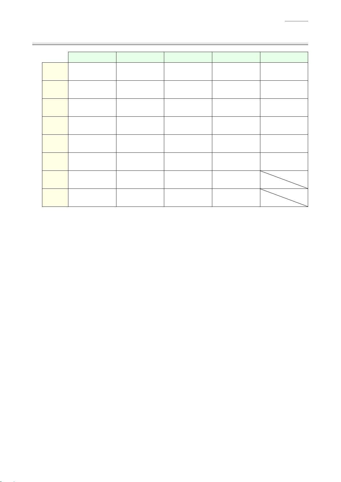
Button Matrix
AP-700
KC0 KC1 KC2 KC3 KC4
KI0 DUET
KI1 SETTING REPEAT
KI2
KI3
KI4 EXIT SALON
KI5 ROOM
KI6 ENTER METRONOME BRILLIANCE
KI7
/k
(Start/Pause)
ELECTRIC
PIANO
FRENCH
CATHEDRAL
OPERATION
LOCK
HARPSI./VIB.
REC STRINGS SONG BASS
u
(Arrow)
LAYER
s
(Rewind)
BERLIN
GRAND
CONCERT
PLAY
w
(Arrow)
DUTCH
CHURCH
TEMPO
w
HAMBURG
GRAND
d
(Fast forward)
ORGAN VOLUME
STANDARD
HALL
q
(Arrow)
TEMPO
q
USB
(Stop)
VIENNA
GRAND
(Arrow)
BERLIN
Y
i
HALL
– 6 –
Page 9
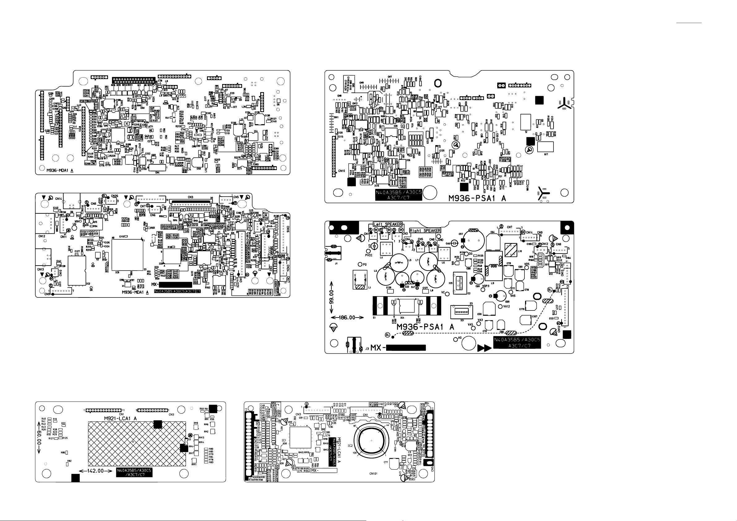
PRINTED CIRCUIT BOARDS
Main PCB: M936-MDA1 Power Amp PCB: M936-PSA1
AP-700
LCD PCB: M921-LCA1
– 7 –
Page 10
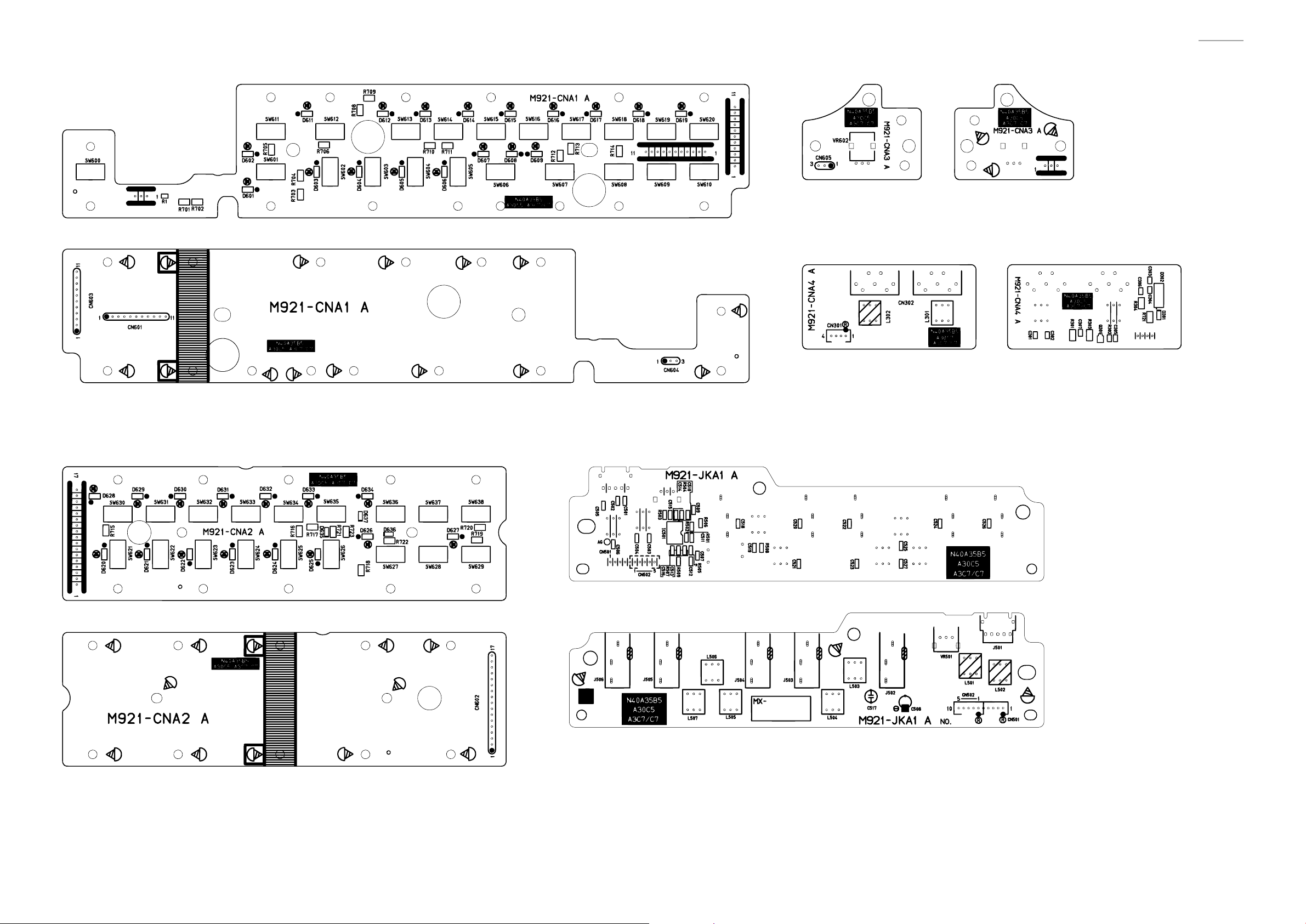
Console PCB: M921-CNA1 Console PCB: M921-CNA3
MIDI PCB: M921-CNA4
AP-700
Console PCB: M921-CNA2
Line PCB: M921-JKA1
– 8 –
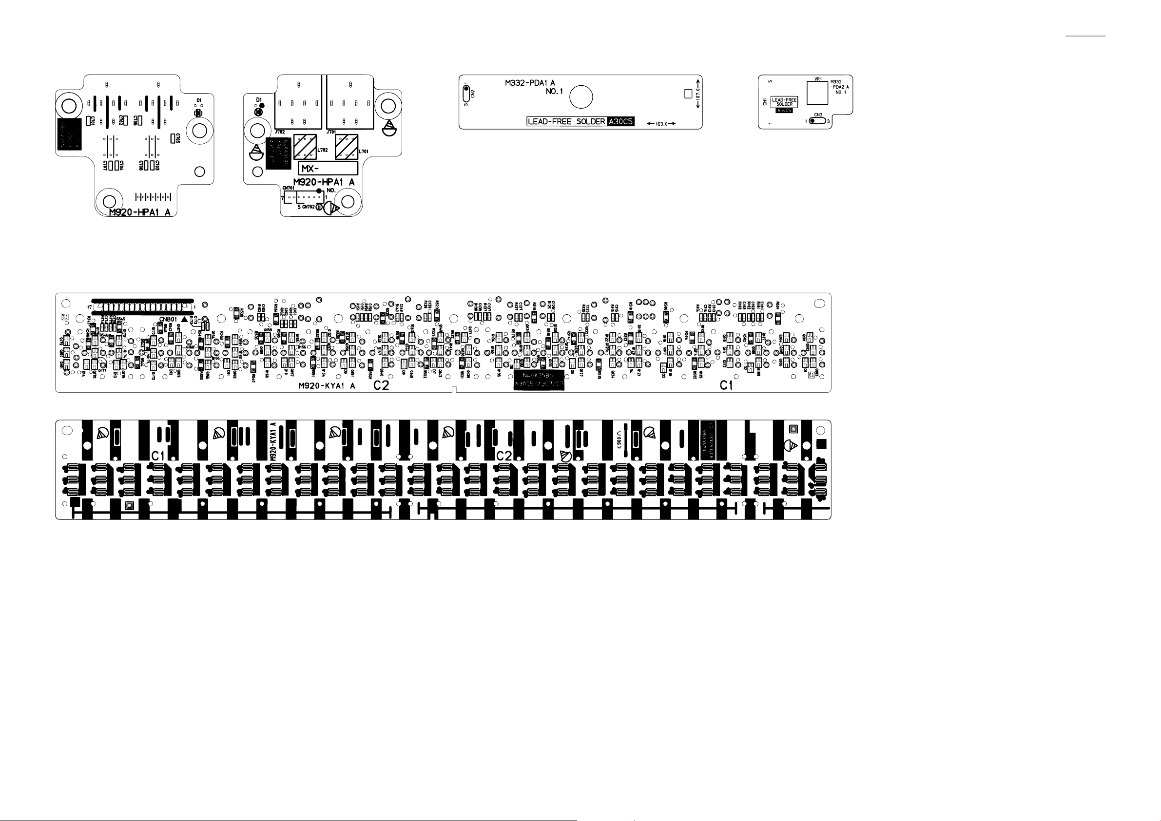
Page 11
AP-700
Phones PCB: M920-HPA1
Keyboard PCB: M920-KYA1
Pedal PCB: M332-PDA1 Pedal PCB: M332-PDA2
– 9 –
Page 12
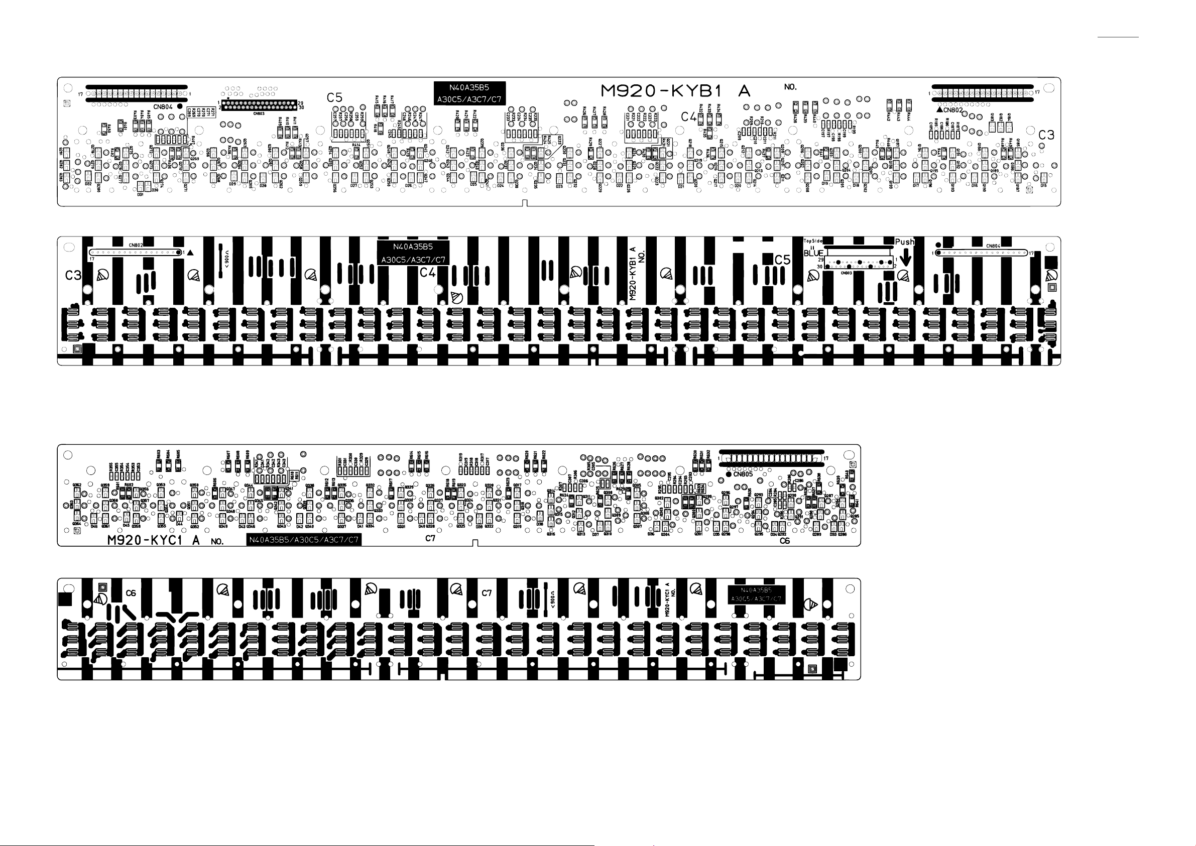
Keyboard PCB: M920-KYB1
AP-700
Keyboard PCB: M920-KYC1
– 10 –
Page 13
DISASSEMBLY
Y
About Repair
• The photos show a prototype, so the appearance of parts may slightly differ from the actual parts.
• To avoid damages to the instrument and fl oor, lay the instrument on a mattress or blanket before
starting disassembling.
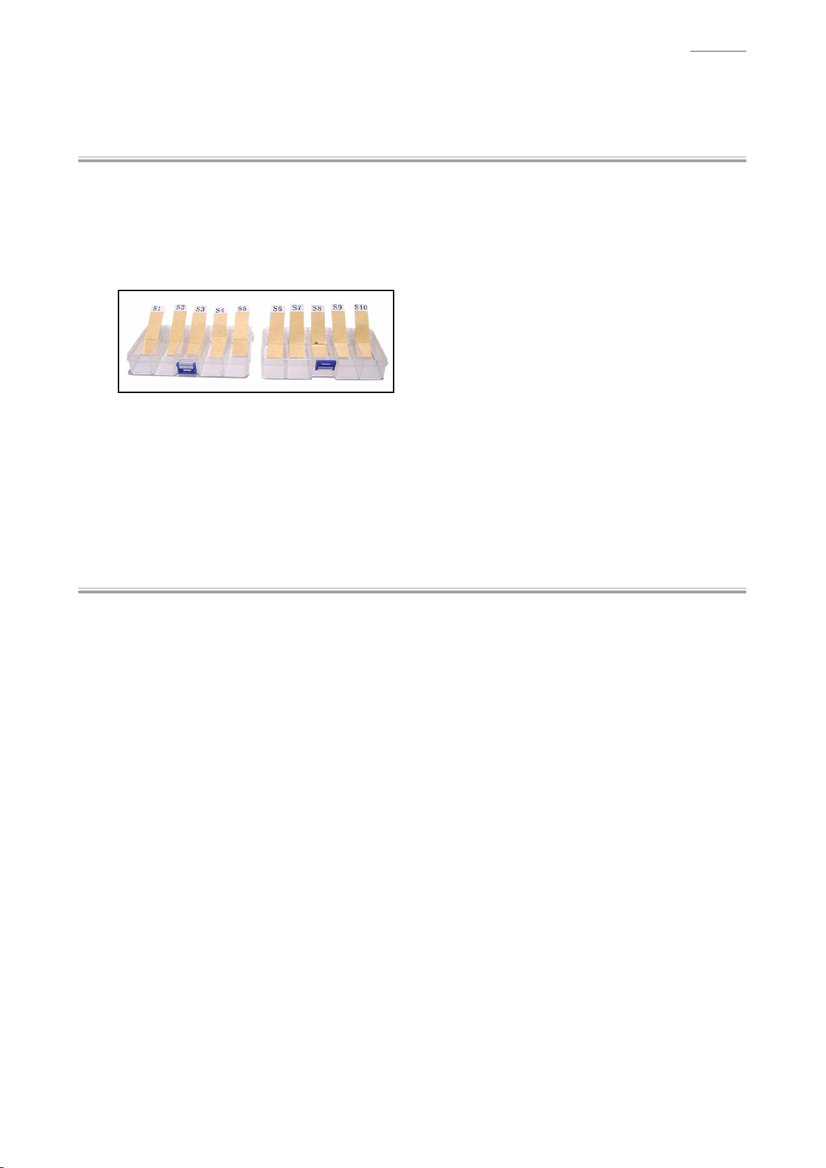
• There are several kinds of screws. Be sure to use the correct type of screws when assembling.
It is advisable to sort the screws as shown below after removing them.
• If a screw cap is attached to the screw, remove it.
When assembling, reattach the screw cap.
AP-700
• Check how cables are wired before removing cables.
When assembling, wire the cables in the same manner as they were before disassembly.
• If a cable is bound by cable tie, tape or similar item, remove it as necessary.
When assembling, bind the cable as it was before disassembly.
Y
Before Starting Repair or Servicing
• Remove the AC adaptor, AC cord or batteries.
• Remove accessories such as the music stand.
– 11 –
Page 14
AP-700
Y
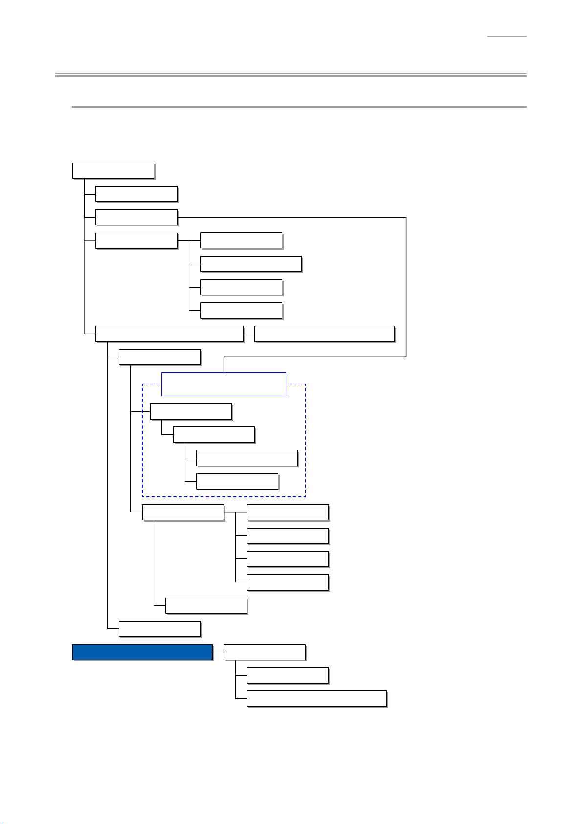
Disassembly Procedures
Flowchart
[NOTE] Some of the major components may be removed/replaced without removing the piano unit
from the stand. Remove the piano unit from the stand as necessary according to the work
environment and with due consideration for safety.
Assembled Product
A. Pedal Unit
B. Stand
F. BOX/PCB
C. TOP BOARD UNIT2, TOP BOARD UNIT1
E. KEY COVER UNIT
The piano unit must be removed from
the stand when performing a repair.
P. SIDE BOARD
K. Console Unit
G. PCB UNIT/MAIN
H. PCB UNIT/POWER & AMP
I. PCB UNIT/JKA1
J. PCB UNIT/CNA4
Q. SIDE RACK UNIT
R. FRONT BOARD UNIT
S. PCB UNIT/HPA1
D. BOARD UNIT/TSP, SCORE BASE UNIT
L. PCB UNIT/CNA1
U. KEYBOARD UNIT
T. SPEAKER
Disassembly of the KEYBOARD UNIT
M. PCB UNIT/CNA2
N. BACK LIGHT UNIT
O. TWEETER
A. KEY
B. HAMMER
C. PCB UNIT/KY AND RUBBER CONTACT
– 12 –
Page 15
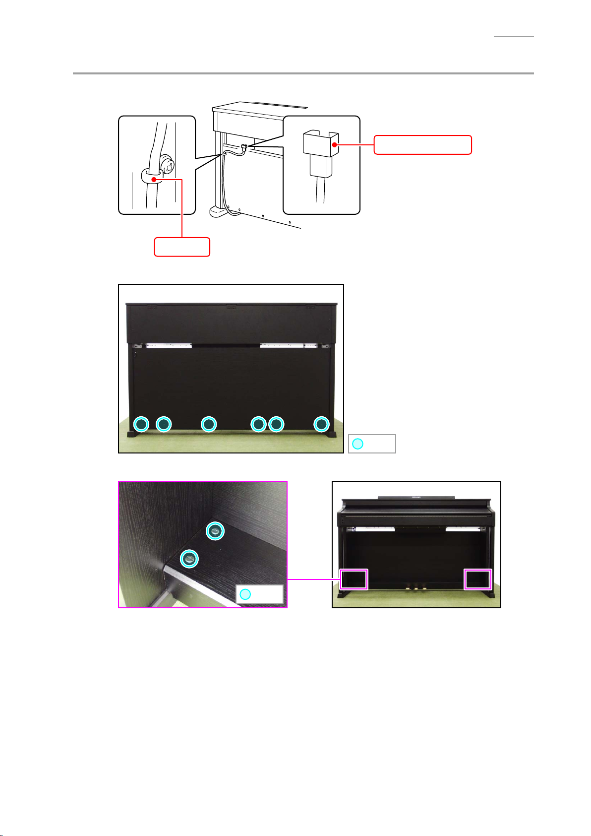
A. Remove the Pedal Unit
A-1. Disconnect the pedal connector from the piano unit.
Clip
A-2. Undo six screws on the back surface.
AP-700
Pedal connector
A-3. Undo four screws.
: Screw
: Screw
– 13 –
Page 16
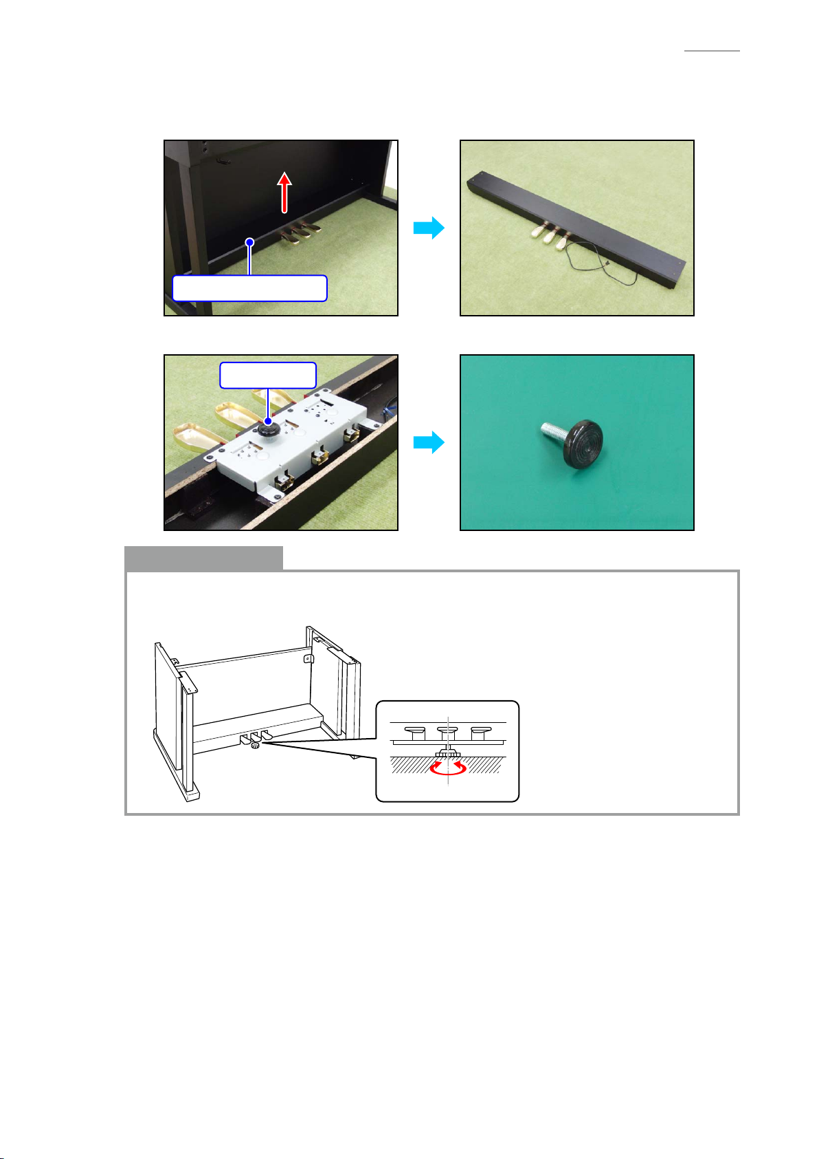
A-4. Remove the PEDAL BOARD UNIT.
[NOTE] The piano unit and stand become slightly unstable when the PEDAL
removed. Use caution so that the piano unit doesn’t fall or the stand doesn’t fall over.
PEDAL BOARD UNIT
A-5. Turn the ADJUSTER to remove it.
ADJUSTER
AP-700
BOARD UNIT is
Notes on Assembly
• Be sure to adjust the ADJUSTER height.
[NOTE] The pedal unit may be damaged if the pedal is operated without height adjustment.
– 14 –
Page 17
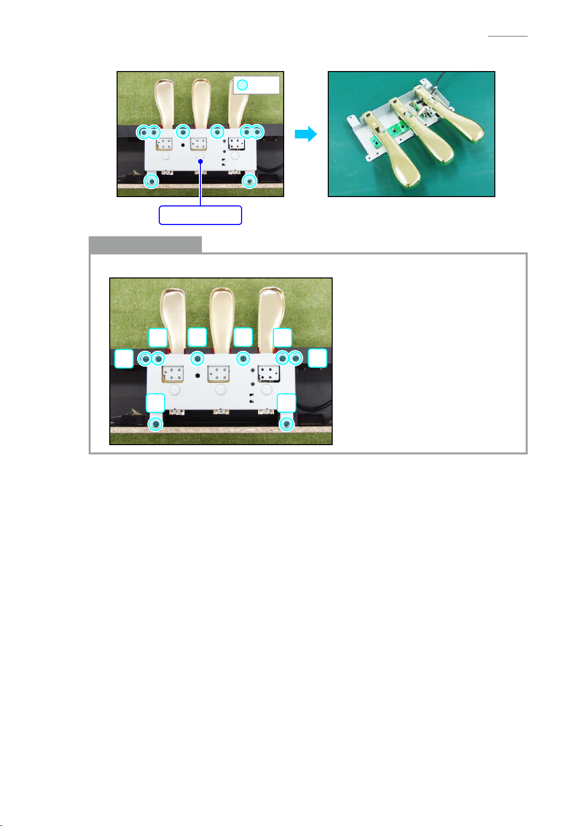
A-6. Undo eight screws and remove the PEDAL UNIT.
: Screw
PEDAL UNIT
Notes on Assembly
• Tighten the screws for the PEDAL UNIT in the order of the numbers shown below.
AP-700
7 8
5
21
6
43
– 15 –
Page 18
B. Remove the Stand
[NOTE] Disassembling or assembling the stand must be done by two or more people.
[NOTE] When disassembling or assembling, take precautions, such as closing the key cover and
tape it closed, so as not to get a hand caught.
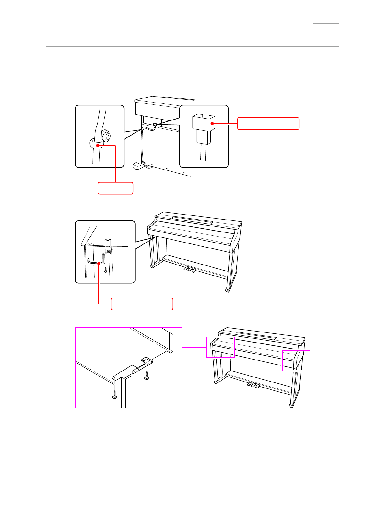
B-1. Disconnect the pedal connector from the piano unit.
Pedal connector
Clip
AP-700
B-2. Undo one screw and remove the
Headphones hook
B-3. Undo four screws on the bottom surface.
headphones hook
.
– 16 –
Page 19
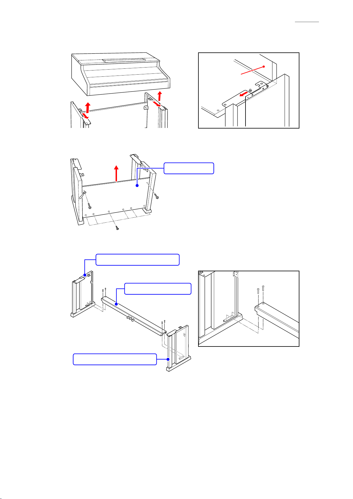
B-4. Place the piano unit on the fl oor.
[NOTE] Please do so with the key cover closed.
Back surface
B-5. Undo eight screws on the back surface and remove the BACK BOARD.
[NOTE] There are two types of screws. Be sure to use the correct screw when reassembling.
BACK BOARD
AP-700
B-6. Undo four screws and remove the SIDE BOARD UNIT/LEFT, SIDE BOARD UNIT/RIGHT, and
PEDAL BOARD UNIT.
SIDE BOARD UNIT/LEFT
PEDAL BOARD UNIT
SIDE BOARD UNIT/RIGHT
– 17 –
Page 20
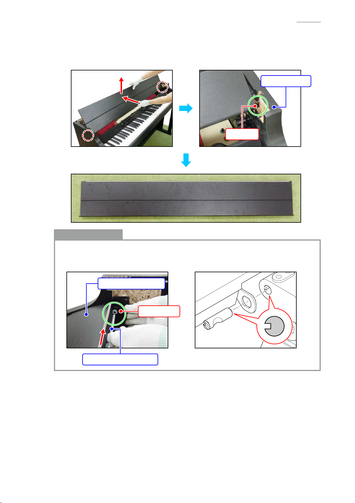
C. Remove the TOP BOARD UNIT2, TOP BOARD UNIT1
C-1. Close the piano lid and undo six screws.
C-2. Lift the TOP BOARD UNIT2.
AP-700
: Screw
TOP BOARD UNIT2
C-3. Undo two screws and remove the BRACKET and TOP BOARD UNIT2.
BRACKET
: Screw
– 18 –
Page 21
Notes on Assembly
• Assemble the TOP BOARD UNIT 2 so that its spring fi ts securely into the plate of the TOP
BOARD UNIT 1.
C-4. Slide the TOP BOARD UNIT1 to remove it.
AP-700
TOP BOARD UNIT1
Notes on Assembly
• Assemble the TOP BOARD UNIT1 so that the brackets on the TOP BOARD UNIT1 and those
on the main case fi t.
– 19 –
Page 22
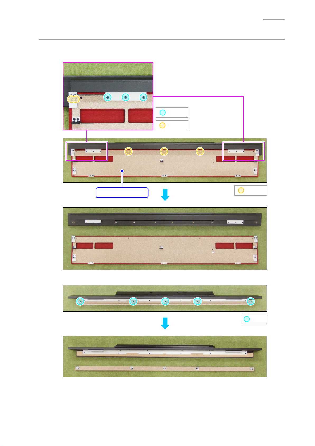
D. Remove the BOARD UNIT/TSP, SCORE BASE UNIT
D-1. Undo 13 screws and remove the BOARD UNIT/TSP.
[NOTE] There are two types of screws. Be sure to use the correct screw when reassembling.
: Screw A
: Screw B
AP-700
BOARD UNIT/TSP
D-2. Undo fi ve screws.
: Screw B
: Screw
– 20 –
Page 23
D-3. Undo six screws.
D-4. Undo 12 screws and remove the SCORE BASE UNIT.
AP-700
: Screw
: Screw
SCORE BASE UNIT
Notes on Assembly
• To assemble the SCORE BASE UNIT, tighten the screws while holding down the unit along
the red lines shown below.
– 21 –
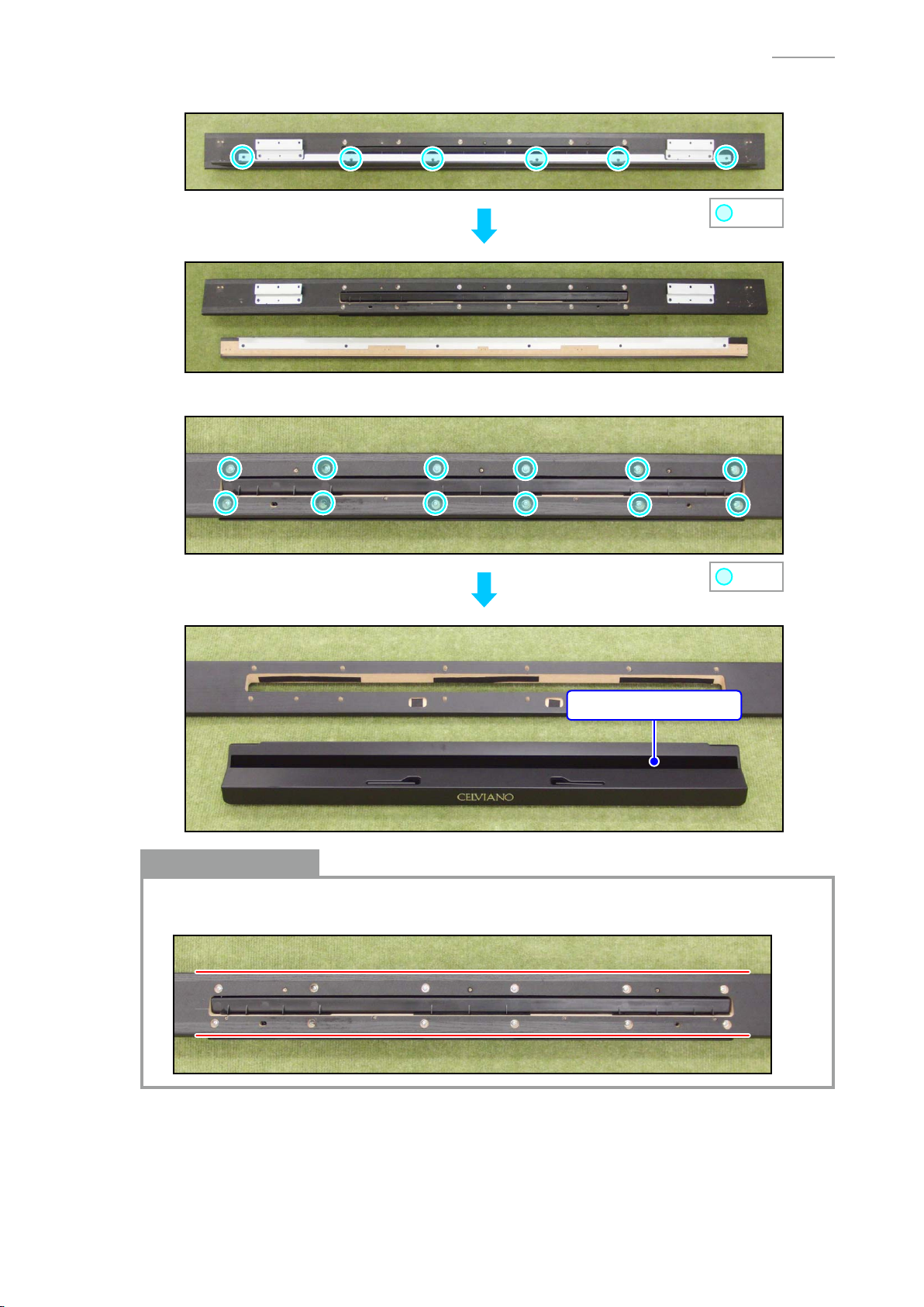
Page 24
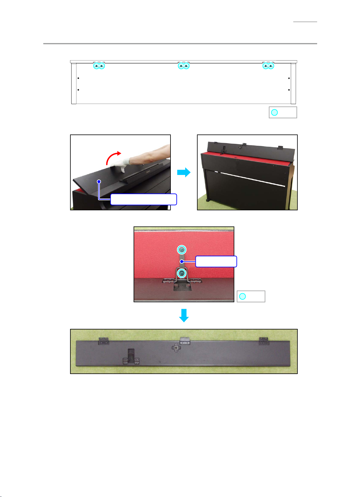
E. Remove the KEY COVER UNIT
E-1. Close the key cover.
E-2. Undo two screws and remove the BRACKET.
Remove the other side in the same manner.
BRACKET
: Screw
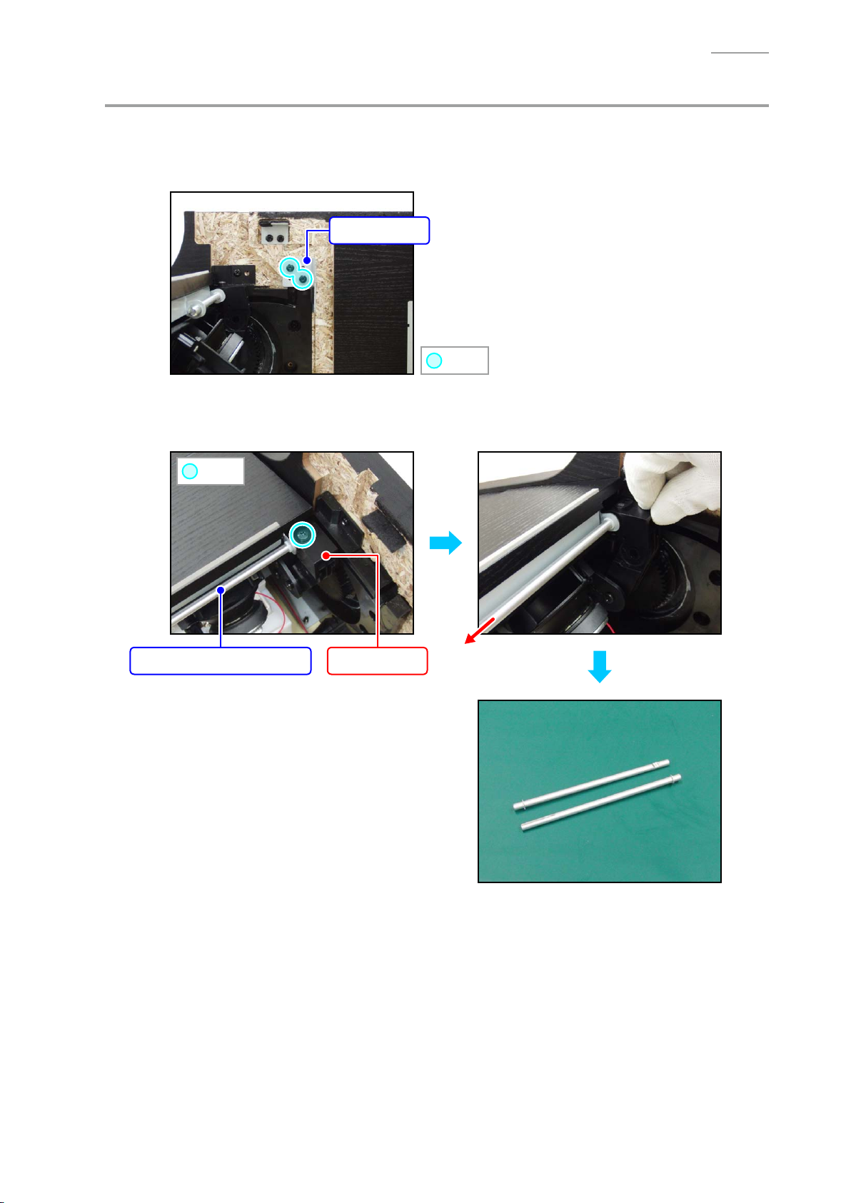
E-3. Undo one screw and while lightly holding the damper in place, remove the SHAFT/for KEY
COVER (with the E-RING).
Remove the other side in the same manner.
AP-700
: Screw
SHAFT/for KEY COVER
Damper
– 22 –
Page 25
AP-700
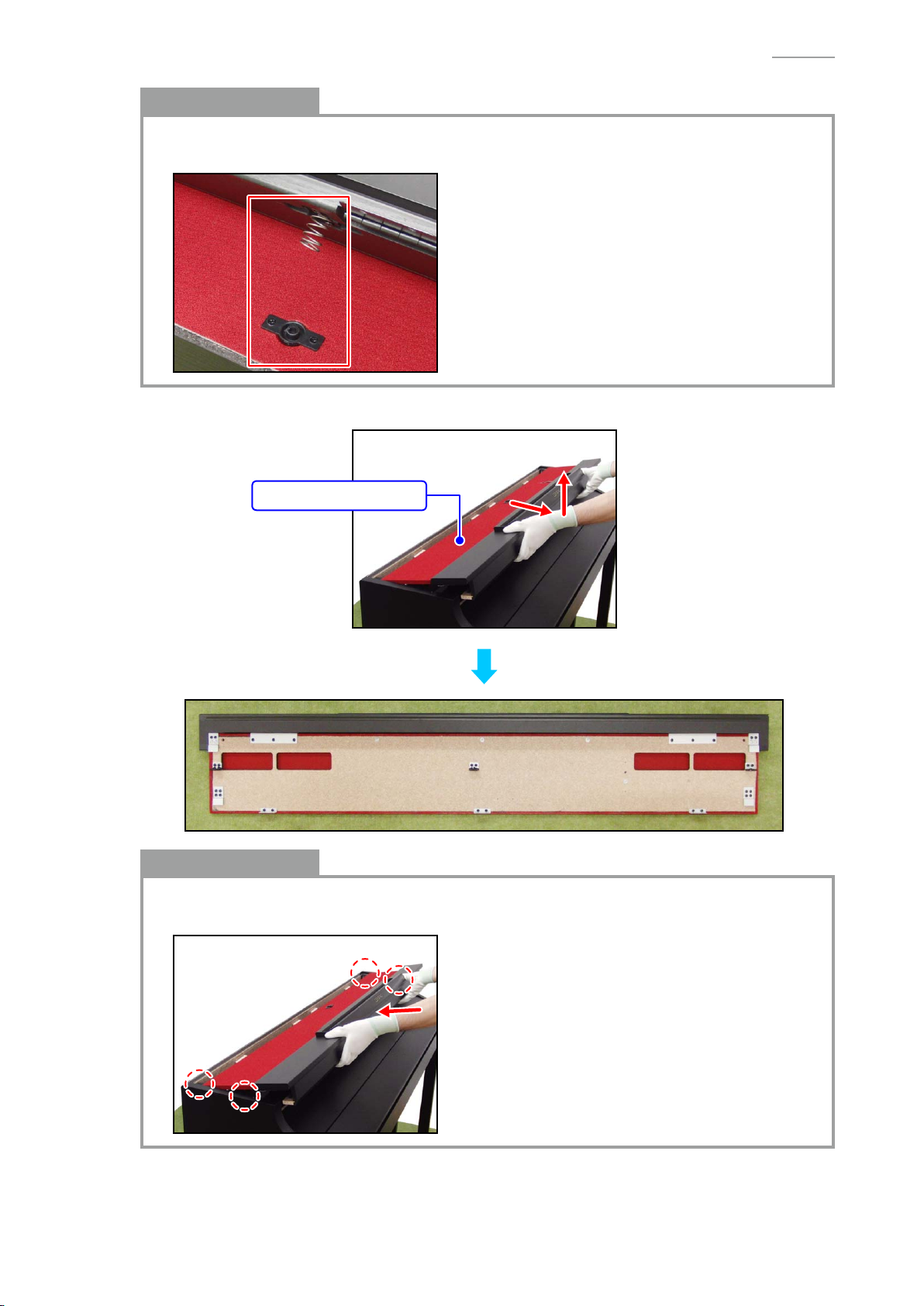
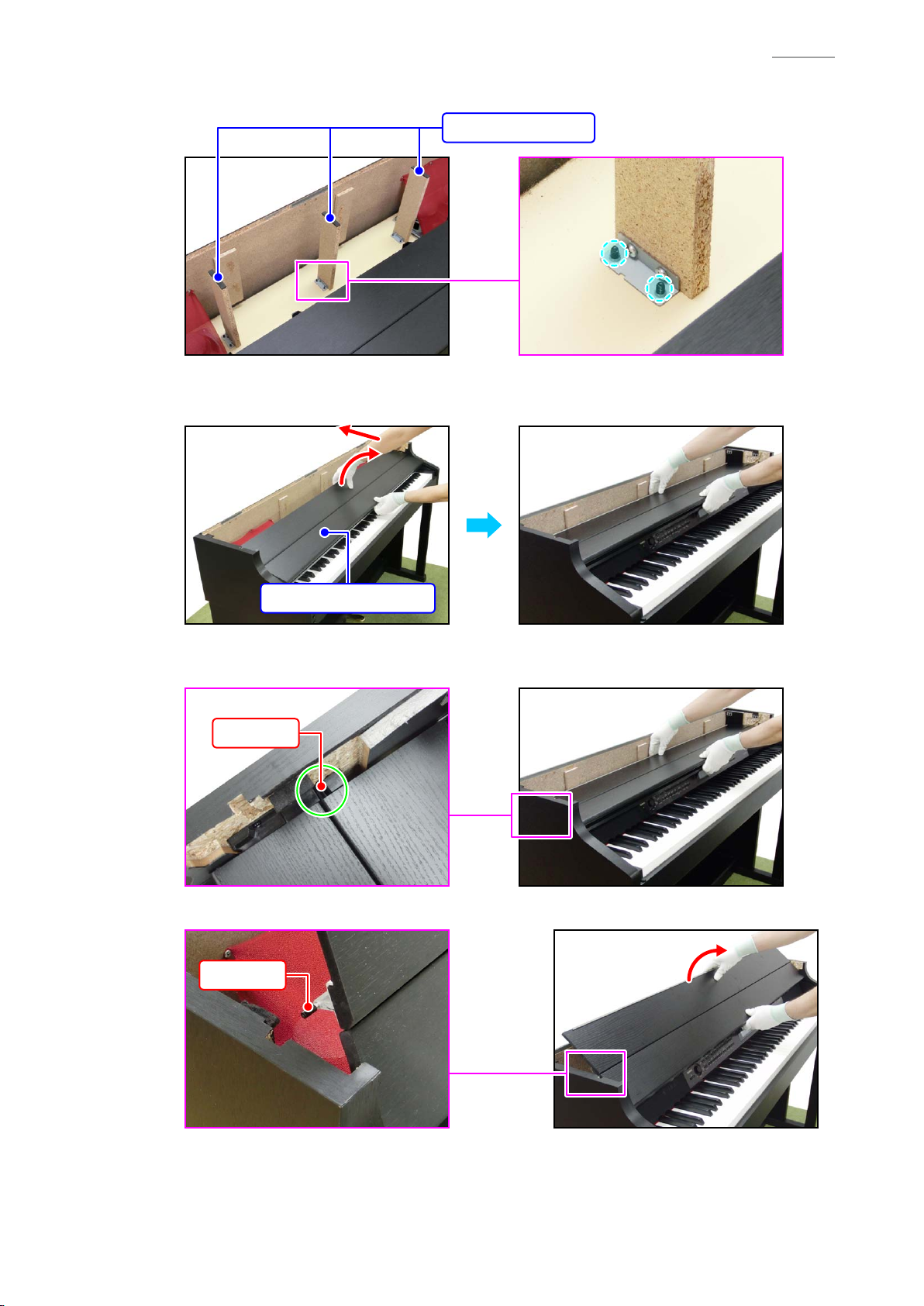
E-4. Undo six screws on the bottom surface and remove three SUPPORT BOARD.
SUPPORT BOARD
E-5. While slightly lifting the rear cover of the KEY COVER UNIT, slide the KEY COVER UNIT all
the way to the rear.
KEY COVER UNIT
E-6. Check that the sliding pin on both sides of the rear cover of the KEY COVER UNIT is visible
when seen from above the rail.
Pin
E-7. Lift the rear cover of the KEY COVER UNIT and then disengage the pins from the rail.
Pin
– 23 –
Page 26
AP-700
E-8. While lifting the KEY COVER UNIT, slide the KEY COVER UNIT further toward the rear.
E-9. In the same manner as when disengaging the pins on the rear cover, disengage the pins on
the front cover from the rail and the grooves on the SIDE BOARD, and then remove the KEY
COVER UNIT.
SIDE BOARD
Pin
Notes on Assembly
• To assemble the SHAFT/for KEY COVER, slightly lift the KEY COVER UNIT while holding the
damper in place, and position the hole to insert the SHAFT/for KEY COVER.
• Align the groove on the SHAFT/for KEY COVER to that on the damper.
KEY COVER UNIT
Damper
SHAFT/for KEY COVER
– 24 –
Page 27
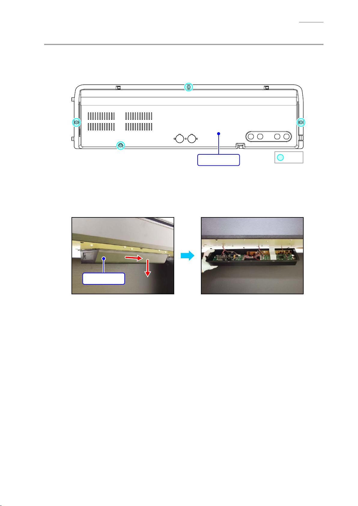
F. Remove the BOX/PCB
[NOTE] If you perform the following steps while the piano unit is attached to the stand, use caution
as not to drop the BOX/PCB nor apply too much tension to the cables and connectors.
F-1. Undo four screws on the bottom surface.
AP-700
BOX/PCB
F-2. Slide the BOX/PCB to remove it.
[NOTE] The BOX/PCB and piano unit are connected with cables. Use caution when removing
the BOX/PCB.
[NOTE] Be sure to hold the BOX/PCB with a hand so as not to add tension to the cables and
connectors.
BOX/PCB
: Screw
– 25 –
Page 28
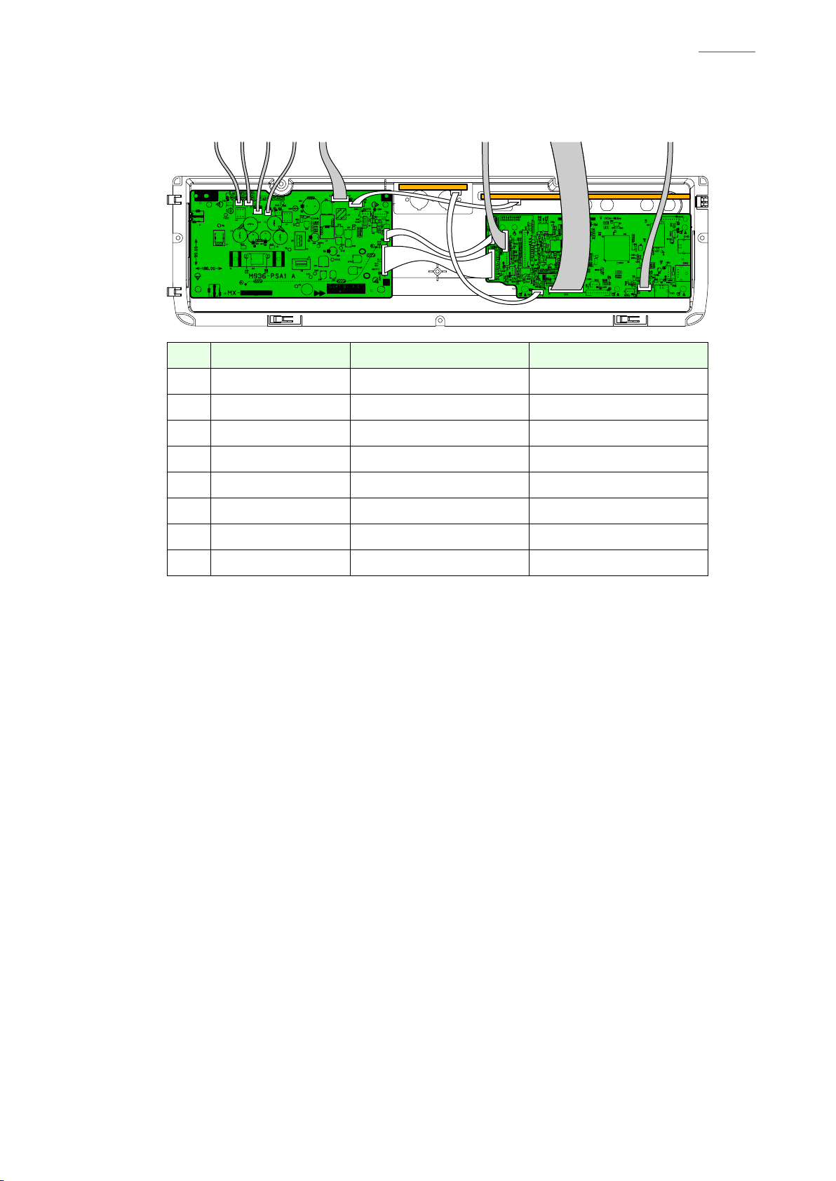
F-3. Disconnect eight cables and remove the BOX/PCB.
[NOTE] Unlock the connector before disconnecting the fl at cable.
No. Type Connected From Connected To
AP-700
Harness Left tweeter PSA1 PCB
Harness Left speakers PSA1 PCB
Harness Right speakers PSA1 PCB
Harness Right tweeter PSA1 PCB
Harness HPA1 PCB PSA1 PCB
Harness LCA1 PCB MDA1 PCB
Flat cable KYB1 PCB MDA1 PCB
Harness Pedal connector MDA1 PCB
– 26 –
Page 29
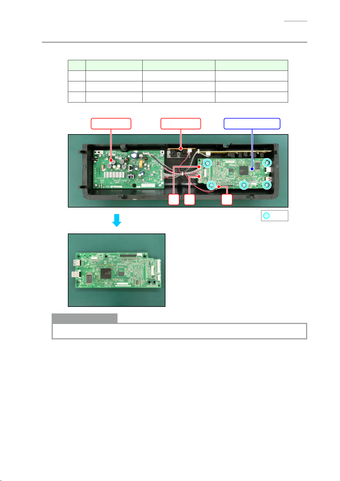
G. Remove the PCB UNIT/MAIN
G-1. Disconnect three cables.
No. Type Connected From Connected To
AP-700
G-2. Undo fi ve screws and remove the PCB UNIT/MAIN.
Harness PSA1 PCB MDA1 PCB
Harness PSA1 PCB MDA1 PCB
Harness CNA4 PCB MDA1 PCB
CNA4 PCBPSA1 PCB
PCB UNIT/MAIN
: Screw
Notes on Assembly
• Connect the cables and before assembling the MDA1 PCB to the BOX/PCB.
– 27 –
Page 30

H. Remove the PCB UNIT/POWER & AMP
AP-700
H-1. Disconnect three
No. Type Connected From Connected To
H-2. Undo four screws and remove the PCB UNIT/POWER & AMP.
PCB UNIT/POWER & AMP
cables
.
Harness PSA1 PCB MDA1 PCB
Harness PSA1 PCB MDA1 PCB
Harness JKA1 PCB PSA1 PCB
MDA1 PCB
JKA1 PCB
: Screw
Notes on Assembly
• When connecting the cables and , support the back of the PCB-side connector by hand
so as not to apply too much load on the MDA1 PCB.
– 28 –
Page 31

I. Remove the PCB UNIT/JKA1
I-1. Disconnect one cable.
No. Type Connected From Connected To
AP-700
I-2. Undo four nuts and remove the PCB UNIT/JKA1.
Harness JKA1 PCB PSA1 PCB
PCB UNIT/JKA1PSA1 PCB
: Nut
– 29 –
Page 32

J. Remove the PCB UNIT/CNA4
J-1. Disconnect one cable.
No. Type Connected From Connected To
AP-700
J-2. Undo three screws and remove the PCB UNIT/CNA4 and BRACKET/for MIDI TERMINAL.
Harness CNA4 PCB PSA1 PCB
PSA1 PCB
PCB UNIT/CNA4
BRACKET
: Screw
PCB UNIT/CNA4
– 30 –
Page 33

K. Remove the Console Unit
K-1. Disconnect the CNA1 PCB cable and tweeter cables from the BOX/PCB.
For details, refer to the “F. Remove the BOX/PCB”.
[NOTE] The cables are secured in place with tape and clips. Be sure to remove the cables
from tape and clips fi rst.
K-2. Undo nine screws.
AP-700
K-3. Lift the Console Unit until it warps slightly.
While maintaining this state, disengage the joint of the SIDE RACK UNIT and console unit on
one side.
[NOTE] Do not apply too much force. Doing so may damage the digital piano.
[NOTE] Be careful not to damage the KEY
FELT.
SIDE RACK UNIT
KEY FELT
Console Unit
: Screw
– 31 –
Page 34

K-4. Disengage the joint on the other side and remove the Console Unit.
CENTER
Console Unit
Notes on Assembly
• Attach the KEY FELT as shown below.
AP-700
1 ± 0.5 mm
SPEAKER PANEL/LEFT & RIGHT KEY FELT
L. Remove the PCB UNIT/CNA1
[REMARK] The PCB UNIT/CNA1 consists of the CNA1 PCB and CNA3 PCB.
L-1. Undo six screws and remove the two PLASTIC BRACKET and BRACKET.
[NOTE] There are two types of screws. Be sure to use the correct screw when reassembling.
LCA1 PCB PCB UNIT/CNA1
: Screw A : Screw B
BRACKET
PLASTIC BRACKET
– 32 –
Page 35

L-2. Disconnect one cable and unsolder one ribbon cable.
No. Type Connected From Connected To
AP-700
L-3. Undo 16 screws and remove the PCB UNIT/CNA1.
Harness CNA1 PCB LCA1 PCB
Ribbon cable CNA1 PCB LCA1 PCB
FABRIC TAPE/5X13
CNA1 PCB CNA3 PCB
: Screw
FABRIC TAPE/5X30
Notes on Assembly
• When replacing the PCB UNIT/CNA1, attach the FABRIC TAPE/5X13 and FABRIC TAPE/5X30
to the CNA1 PCB as shown in the fi gure above.
• Before assembling the PCB UNIT/CNA1, check that the KNOB/for ROTARY, TACT BUTTON (10
pcs), LED COVER with DOUBLE FACED TAPE (14 pcs), LED SPACER (8 pcs), FABRIC TAPE/A,
and FABRIC SHEET/B (2 pcs) have been assembled to the CONSOLE PANEL/MIDDLE.
– 33 –
Page 36

M. Remove the PCB UNIT/CNA2
M-1. Undo four screws and remove the PLASTIC BRACKET and BRACKET.
LCA1 PCBPCB UNIT/CNA2
AP-700
PLASTIC BRACKET
M-2. Unsolder one ribbon cable.
No. Type Connected From Connected To
M-3. Undo 10 screws and remove the PCB UNIT/CNA2.
Ribbon cable CNA2 PCB LCA1 PCB
BRACKET
: Screw
: Screw
Notes on Assembly
• Before assembling the PCB UNIT/CNA2, check that the TACT BUTTON (6 pcs), LED COVER
with DOUBLE FACED TAPE (9 pcs), LED SPACER (5 pcs), and FABRIC TAPE/C (2 pcs) have
been assembled to the CONSOLE PANEL/MIDDLE.
– 34 –
Page 37

N. Remove the BACK LIGHT UNIT
N-1. Undo two screws and remove the BRACKET.
BACK LIGHT UNITCNA2 PCB CNA1 PCB
AP-700
BRACKET
N-2. Disconnect one connector and unsolder two ribbon cables.
No. Type Connected From Connected To
N-3. Undo four screws and remove the BACK LIGHT UNIT.
[NOTE] When you undo the screw, the WASHER also comes off. Be sure to attach the
Harness CNA1 PCB LCA1 PCB
Ribbon cable CNA1 PCB LCA1 PCB
Ribbon cable CNA2 PCB LCA1 PCB
WASHER when assembling.
: Screw
– 35 –
: Screw
WASHER
Page 38

Notes on Assembly
• When replacing the any of following parts, attach the SPONGE/35X60 to the harness as
shown in the fi gure below.
– BACK LIGHT UNIT
– CONNECTOR CABLE (for LCA1 PCB)
• Before assembling the BACK LIGHT UNIT, check that the LCD surfaces on the upper case
side and LCD side are free from dust and dirt.
SPONGE/35X60
AP-700
O. Remove the TWEETER
[NOTE] The basic procedure to remove the part is the same on both sides.
O-1. Undo two screws and remove the TWEETER.
O-2. Unsolder the harness.
No. Left Tweeter Right Tweeter
<Left tweeter> <Right tweeter>
Negative terminal (Black) Negative terminal (White)
Positive terminal (Red) Positive terminal (Red)
TWEETER
– 36 –
Page 39

P. Remove the SIDE BOARD
[NOTE] The basic procedure to remove the part is the same on both sides.
P-1. Undo two screws on the bottom surface.
P-2. Undo two screws on the back surface.
: Screw : Screw
P-3. Undo three screws.
SIDE RACK UNIT
AP-700
SIDE BOARD
: Screw
P-4. Remove the SCREW CAP and undo one screw.
[REMARK] The SCREW CAP is secured with the DOUBLE FACED TAPE.
SCREW CAP
P-5. Remove the SIDE BOARD.
: Screw
– 37 –
Page 40

Q. Remove the SIDE RACK UNIT
[NOTE] The basic procedure to remove the part is the same on both sides.
Q-1. Undo two screws on the bottom surface.
: Screw
Q-2. Undo one screw.
SIDE RACK UNIT
AP-700
Console Unit
: Screw
Q-3. Undo one screw on the side surface and remove the SIDE RACK UNIT and SIDE CASE UNIT.
SIDE RACK UNIT
SIDE CASE UNIT
: Screw
Q-4. Undo two screws and remove the SIDE CASE UNIT from the SIDE RACK UNIT.
SIDE RACK UNIT
: Screw
SIDE CASE UNIT
– 38 –
Page 41

Q-5. Remove the RUBBER FOOT.
RUBBER FOOT
R. Remove the FRONT BOARD UNIT
R-1. Disconnect the HPA1 PCB cable from the BOX/PCB.
For details, refer to the “F. Remove the BOX/PCB”.
R-2. Undo six screws on the bottom surface and remove the FRONT BOARD UNIT.
AP-700
FRONT BOARD UNIT
S. Remove the PCB UNIT/HPA1
S-1. Disconnect the HPA1 PCB cable from the BOX/PCB.
For details, refer to the “F. Remove the BOX/PCB”.
S-2. Undo two screws and remove the PCB UNIT/HPA1.
PCB UNIT/HPA1
: Screw
: Screw
– 39 –
Page 42

T. Remove the SPEAKER
[REMARK] There are two speakers each on right and left. The removal procedure is identical for all
speakers.
T-1. To replace the speaker harness, disconnect the speaker cable from the BOX/PCB.
For details, refer to the “F. Remove the BOX/PCB”.
T-2. Undo three screws and remove the COVER NET.
COVER NET
: Screw
T-3. Unsolder the harness.
AP-700
No. Left Speaker Right Speaker
T-4. Undo four screws and remove the SPEAKER and SPEAKER NET.
<Example> <Example>
Left speaker on the left side Right speaker on the right side
Negative terminal (Black) Negative terminal (White)
Positive terminal (Red) Positive terminal (Red)
: Screw
: Screw
Notes on Assembly
• The
SPEAKER NET
assembling.
SPEAKER NETSPEAKER
has front and back faces. Face the smooth surface to the bottom when
– 40 –
Page 43

U. Remove the KEYBOARD UNIT
U-1. Remove the BOX/PCB.
For details, refer to the “F. Remove the BOX/PCB”.
U-2. Undo 15 screws and remove seven PLASTIC BASE.
[NOTE] The PLASTIC BASE at the center and the both ends are screwed at different hole
positions from the others.
AP-700
LEFT
U-3. Undo three screws.
OTHER OTHER
CENTER RIGHT
: Screw
– 41 –
: Screw
Page 44

U-4. Undo 19 screws on the bottom surface and remove the KEYBOARD UNIT.
KEYBOARD UNIT
AP-700
: Screw
Notes on Assembly
• When the KEYBOARD UNIT or FLAT CABLE has been replaced, attach the SPONGE/50X115
to the FLAT CABLE.
FLAT CABLE
SPONGE/50X115
– 42 –
Page 45

Y
Disassembly of the KEYBOARD UNIT
A. Remove the KEY
Overview
<Removing the Keys>
• To remove the keys, you will need two of the tools described below.
• Before removing a black key, you must fi rst remove both white keys on either side of the black
key.
• White keys may be removed with the same procedures as removing black keys.
<Tool>
• The tool used in the photos in this section was converted from a gardening ID tag. The size
and shape of an ID tag accord to the dimensions below.
<Note on Shaping an ID Tag>
• The thickness of the tool must be within 1.2 ~ 1.3 mm. If the tool is too thin, removing keys
become diffi cult. If the tool is too thick, it may damage the rib of the chassis.
AP-700
<Tool Dimensions>
Width:
15~20 mm
Thickness:
within 1.2~1.3 mm
7 mm
R=2.75 mm
Use this part to
remove the key.
– 43 –
Page 46

A-1. Undo 12 screws and then remove four key spacers.
[NOTE] There are four types of the key spacers. Be sure to use the correct type when assembling.
Key spacer A Key spacer B Key spacer C Key spacer D
Key spacer A
AP-700
: Screw
Key spacer B
Key spacer C
Key spacer D
<How to Identify Key Spacers>
• There is an identifi cation marking on the upper right or upper left of the key spacer.
Parts Name Marking
Key spacer A SPC-A
Key spacer B SPC-B
Key spacer C SPC-C
Key spacer D SPC-D
– 44 –
Page 47

A-2. Insert the two tools between the rib of the chassis and a key and then remove the key.
[NOTE] When you insert the tools to a certain extent, the latch which fi xing the key is
disengaged and the keys are lifted for removal.
Tools
Chassis
<Cross-section Image>
AP-700
Tool
KEYRib of the chassis
– 45 –
Page 48

Notes on Assembly
<Reference: Musical Scale>
• The scale shown below is used for the piano.
Scale
AP-700
Note
SA
(A)
C
(Do)
B C D E F G A B C D E F G A B C D E F G A B
D
(Re)
E
(Mi)
F
(Fa)
G
(So)
<Keyboard Layout>
• Refer to the illustration on the right and install the white keys in
the correct order of the note.
[NOTE] A note is marked at the upper end of each key. You
may ignore the number marked after the note.
[NOTE] The parts for the keys at both ends and the second
one from the left end differ from the other keys with the
same notes.
[NOTE] Install the keys in the order of C → D → E → F → G →
A → B in the range marked with a red broken line in the
illustration (the range between the third key from the
left end and the second key from the right end).
• All black keys are identical; therefore, they may be installed in
any order.
A
(La)
B
(Ti)
C D E F G A B C D E F G A B C D E F G A B C D E F G A B SC
Left end Right end
Note
D F ASA B
SA
B C D E F G A B SC
BE GC
(C)
SC
– 46 –
Page 49

Caution When Replacing with New Parts
• A set of new white keys consists of the parts below.
[NOTE] Remove the part indicated with a red line before use.
[NOTE] The parts for the keys at both ends and the second one from the left end differ from
the other keys with the same notes.
No. Parts Name Note Remarks
WHITE KEY/SA SA (A) Designated for the left end
WHITE KEY/B B Designated for the second key from the left end
WHITE KEY/CEGB C / E/ G / B A set of C/E/G/B
WHITE KEY/DFA D/F/A A set of D/F/A
WHITE KEY/SC SC (C) Designated for the right end
AP-700
BE GC
D F ASA B
SC
– 47 –
Page 50

Applying Grease
• Apply grease on the guide for keys as necessary after the keys are replaced.
[NOTE] Apply grease on the side of the guide for keys.
Code No. Parts Name Specifi cation
94816509 SLICONE GREASE G-501.80G-PC
Guide for black key
AP-700
Guide for white key
Guide for white key
Apply grease here
(In the area indicated in green)
Guide for black key
Apply grease here
(In the area indicated in green)
– 48 –
Page 51

Installing the Keys
• Follow the steps below to install the white and black keys.
[NOTE] The white keys must be arranged in a specifi c order. Install them according to the
correct order of the note. Be sure to install the white key at a hammer for a white key.
[NOTE] Install a black key before installing the white keys on its sides.
Be sure to install the black key at a hammer for a black key.
(1) Assemble a key to a hammer.
(2) Press the key to fi t the hole of the key with the protrusion of the chassis.
(3) Press the key and check to see if it moves properly.
Fit securely into the chassis.
AP-700
Assemble a key to a hammer.
<Locations to Install the White and Black Keys>
• Install a white key in the position of a guide for white key.
• Install a black key in the position of a guide for black key.
Guide for black key
Guide for white key
– 49 –
Page 52

B. Remove the HAMMER
B-1. Place the chassis upside down so that the hammers are visible.
<Identifying the Hammers When Placed Upside Down>
• The size chassis hole differs between white and black keys.
The hammer for a black key goes into a bigger hole, while the hammer for a white key goes
into a smaller hole.
Hammer for white key Hammer for black key
B-2. Press the chassis with the tip of tweezers.
AP-700
B-3. While catching a hammer with tweezers, set the tweezers against the resin part of the chassis.
B-4. Using the chassis-tweezer contact as a fulcrum point, press down against the resin part in the
direction of the red arrow shown below, and then disengage the hammer.
[NOTE] You must press the resin part of the hammer. Pressing on the metal part of the
hammer may damage the area connected to the resin.
[NOTE] If a hammer does not disengage easily, perform the steps while lifting the hammer.
Tweezers
Press down the resin part.
Fulcrum point
– 50 –
Page 53

Kinds of Hammers
• There are several kinds of hammers.
The type of a hammer may be identifi ed by the code engraved on it.
Type of Hammer: “W” for a white key, “B” for a black key.
Hammer Code: The hammers for white keys are coded W1, W2, W3, and W4.
The hammers for black keys are coded B1, B2, B3, and W4.
Type of Hammer (for a white key)
Hammer Code (for a white key)
Type of Hammer (for a black key)
AP-700
Hammer Code (for a black key)
Location to Install the Hammers
• A hammer must be installed at the correct location according to its type.
The combination of hammers and keys are shown below.
<Hammers for black keys>
B1 (9 keys) B2 (9 keys) B3 (9 keys) B4 (9 keys)
W1 (13 keys)
W2 (13 keys)
W3 (13 keys) W4 (13 keys)
<Hammers for white keys>
– 51 –
Page 54

AP-700
Installing the Hammers
• Follow the steps below to install the hammers for white and black keys.
[NOTE] The hammers must be arranged in a specifi c order. Install them according to the
correct order.
[NOTE] If a hammer does not move smoothly, check to see if it is installed at the correct
location.
(1) Use the tweezers to set a hammer at its correct location.
(2) Press the chassis with the tip of tweezers.
(3) Using the chassis-tweezers contact as a fulcrum point, press down the metal part of the
hammer in the direction of the red arrow shown below, and then install the hammer.
[NOTE] Be careful not to damage the felt.
Tweezers
Press down against the metal part.
Locked at this point
Fulcrum point
Be careful not to damage the felt.
– 52 –
Page 55

C. Remove the PCB UNIT/KY AND RUBBER CONTACT
[NOTE] The PCB UNIT/KY AND RUBBER CONTACT consists of the KYA1 PCB, KYB1 PCB, and
KYC1 PCB.
C-1. Unlock the connector and remove the FLAT CABLE.
C-2. Undo 23 screws and remove the PCB UNIT/KY AND RUBBER CONTACT.
FLAT CABLE
: Screw
AP-700
KYB1 PCBKYA1 PCB KYC1 PCB
PCB UNIT/KY AND RUBBER CONTACT
C-3. Remove eight RUBBER CONTACT.
[NOTE] One RUBBER CONTACT differs in length.
RUBBER CONTACT Short RUBBER CONTACT
RUBBER CONTACT/AG
– 53 –
RUBBER CONTACT/AC
Page 56

Installing the PCB UNIT/KY AND RUBBER CONTACT
(1) Secure the PCB UNIT/KY AND RUBBER CONTACT with 23 screws.
[NOTE] Tighten the screws while pressing the PCB in the direction of the red arrow shown
below.
(2) Connect the FLAT CABLE to the KYB1 PCB and lock the connector.
[NOTE] Insert it fi rmly and lock up.
AP-700
FLAT CABLE
How to Install RUBBER CONTACT
• Lightly insert the tip of a RUBBER CONTACT into the PCB fi rst, and then press it in using the
end of a paper clip.
[NOTE] Do not press with too much force. Doing so may damage the RUBBER CONTACT.
– 54 –
Page 57

DIAGNOSTIC PROGRAM
Y
Test Items / Flowchart
Start
[METRONOME] + [TEMPO w] + [TEMPO q] + POWER ON
Launch the Diagnostic Program
(Sub CPU Check)
[Arrow w]
LED Check
[Arrow w]
LCD Check
[Arrow w] × 2
Button Check
AP-700
[Arrow w]
Keyboard Check
[Arrow w]
Pedal Check
[Arrow w]
PHONES Check
[Arrow w]
MIDI Check
[Arrow w]
USB Check
[Arrow w]
USB Host Check
[Arrow w] × 3
ROM Version Check
[Arrow w]
PREPARATION: Headphones
PREPARATION: MIDI cable
PREPARATION: PC, USB cable
PREPARATION: USB flash drive
Flash Memory Check
[Arrow w] × 2
RAM Check
POWER OFF
End the Diagnostic Program
– 55 –
Page 58

Y
Preparation
(1) Connect the AC adaptor.
(2) Connect the pedal.
(3) Adjust the volume so that it is at about 1/3 of the full volume.
(4) Have a headphones and MIDI cable ready.
[NOTE] The “PHONES Check” cannot be performed without a headphones.
The “MIDI Check” cannot be performed without a MIDI cable.
(5) Have a PC and USB cable ready.
For information about PC system requirements, refer to the User’s Guide.
[NOTE] The “USB Check” cannot be performed without a PC and USB cable.
(6) Have a USB fl ash drive ready.
[NOTE] The “USB Host Check” cannot be performed without a USB fl ash drive.
Y
Test Procedures
AP-700
[REMARK] Refer to the below for the pitch of the confi rmation or error tones which you hear during the
test.
A0# C1# D1# F1# G1# A1# C2# D2# F2# G2# A2# C3# D3# F3# G3# A3# C4# D4# F4# G4# A4# C5# D5# F5# G5# A5# C6# D6# F6# G6# A6# C7# D7# F7# G7# A7#
A0 B0 C1 D1 E1 F1 G1 A1 B1 C2 D2 E2 F2 G2 A2 B2 C3 D3 E3 F3 G3 A3 B3 C4 D4 E4 F4 G4 A4 B4 C5 D5 E5 F5 G5 A5 B5 C6 D6 E6 F6 G6 A6 B6 C7 D7 E7 F7 G7 A7 B7 C8
[REMARK] Refer to the below for the LED ON status.
• Lit in Yellow: /k (left)
• Lit in Red: OPERATION LOCK, BERLIN GRAND, HAMBURG GRAND, VIENNA GRAND,
ELECTRIC PIANO, HARPSI./VIB., STRINGS, ORGAN, BASS, DUET, DUET PAN,
REPEAT, s, d, Y, /k (right), REC
• Lit in Red: ROOM, SALON, DUTCH CHURCH, STANDARD HALL, BERLIN HALL,
FRENCH CATHEDRAL, METRONOME, EXIT, Arrow u, Arrow w, Arrow q, Arrow i,
ENTER, LAYER, USB
– 56 –
Page 59

A. Launch the Diagnostic Program (Sub CPU Check)
A-1. Turn on the power while holding down the [METRONOME], [TEMPO w] and [TEMPO q]
buttons.
[REMARK] There are two sets of the [w] and [q] buttons.
In this manual, the buttons are identifi ed by indicating [Arrow] or [TEMPO].
[NOTE] “CASIO” appears when the power is turned on.
Hold down three buttons until “CASIO” disappears.
[NOTE] When the test is fi
<Screen during the diagnostic program startup>
nished, be sure to press the power button to turn off the power.
[TEMPO] buttons
[Arrow] buttons
AP-700
A-2. Once the diagnostic program is launched, the “Sub CPU Check” is performed automatically.
When the test result is “OK”, the diagnostic program top screen appears.
<Top screen>
How to operate the diagnostic program
• The diagnostic program includes test items not performed.
Please skip the items which are not described in this manual.
• To skip an item, press the [Arrow w] button.
To return to the previous item, press the [Arrow q] button.
* Some test items may not be skipped.
• Pressing the [EXIT] button while on a test screen will return to the top screen.
* Some test items do not allow you to go back to the top screen.
* The diagnostic program ends and the User Mode launches when you press the [EXIT] button
while in the top screen.
– 57 –
Page 60

B. LED Check
K
K
K
K
C0 BLOC
C1 BLOC
C2 BLOC
C3 BLOC
B-1. Press the [Arrow w] button and then check that the following screen appears and also that
the “C0 BLOCK” LEDs only are lit.
• Lit in Red: OPERATION LOCK, BERLIN GRAND, HAMBURG GRAND, VIENNA GRAND,
ELECTRIC PIANO, HARPSI./VIB., STRINGS, ORGAN, BASS
AP-700
B-2. Press the [HAMBURG GRAND] button and then check that the following screen appears and
also that the “C1 BLOCK” LEDs only are lit.
• Lit in Yellow: /k (left)
• Lit in Red: DUET, DUET PAN, REPEAT, s, d, Y, /k (right), REC
B-3. Press the [VIENNA GRAND] button and then check that the following screen appears and also
that the “C2 BLOCK” LEDs only are lit.
• Lit in Red: ROOM, SALON, DUTCH CHURCH, STANDARD HALL, BERLIN HALL,
FRENCH CATHEDRAL, METRONOME
B-4. Press the [ELECTRIC PIANO] button and then check that the following screen appears and
also that the “C3 BLOCK” LEDs only are lit.
• Lit in Red: EXIT, Arrow u, Arrow w, Arrow q, Arrow i, ENTER, LAYER, USB
– 58 –
Page 61

B-5. Press the [HARPSI./VIB.] button and then check that the following screen appears and also
that all LEDs are lit.
C. LCD Check
C-1. Press the [Arrow w] button and then check that all dots are lit.
C-2. Press the [HAMBURG GRAND] button and then check that all dots are turned off.
AP-700
C-3. Press the [VIENNA GRAND] button and then check that dots are lit in one-dot intervals,
showing vertical stripes starting from the right end.
C-4. Press the [ELECTRIC PIANO] button and then check that dots are lit in one-dot intervals,
showing vertical stripes starting from the left end.
– 59 –
Page 62

D. Button Check
D-1. Press the [Arrow w] button twice and then check that the following screen appears.
D-2. Press the buttons in the sequence shown in the fi gure below.
1 2 3 4 5 6 7 8 9 10
START
START
11 12 13 14 15 16 17 18 19 20
AP-700
292827262524232221
ENDEND
3736353433323130
If the result passes (OK):
• The confi rmation tone (C6) sounds and “OK:” and button number shown above “XX” appear.
When press the [USB] button at the end, the confi rmation chord (C4/E4/G4) sounds and the
“Keyboard Check” screen appears.
If the result fails (NG):
• If there is a button failure or the buttons are pressed in a wrong sequence, the error tone (F2)
sounds and the NG count appears.
When “NG” occurs three times, the check sequence stops and the program returns to the top
screen.
– 60 –
Page 63

AP-700
E. Keyboard Check
E-1. Check that the following screen appears.
E-2. Press any key and then check that the sound correctly comes out (sine wave) and also that the
following screen appears.
[NOTE] Check the sound while you are at the center of the digital piano.
[REMARK] The “Note” value shows the key position in a hexadecimal number.
[REMARK] The “Velocity” value shows the key velocity in hexadecimal number.
The slower you press the key, the smaller the value becomes.
The faster you press the key, the larger the value becomes.
E-3. Press the “ELECTRIC PIANO” button and then check that the following screen appears.
E-4. Press a key and then check that the sound comes out (sine wave) as follows.
[NOTE] Check all keys.
Key Left Speaker Right Speaker Remarks
Press a key
halfway
Press a key
all the way
C6 sine wave When the contact
C6 sine wave C4 sine wave
When the contact
turned on
is turned on
and are
– 61 –
Page 64

F. Pedal Check
F-1. Press the [Arrow w] button and then check that the following
screen appears.
F-2. Press and release the SOFT pedal and then check that the
following screen appears.
[REMARK] The confi rmation tone (E4) sounds.
<When the pedal is pressed> <When the pedal is released>
AP-700
SOFT DAMPER
SOSTENUTO
F-3. Press and release the SOSTENUTO pedal and then check that the following screen appears.
[REMARK] The confi rmation tone (G4) sounds.
<When the pedal is pressed> <When the pedal is released>
F-4. Press and release the DAMPER pedal and then check that the following screen appears.
[NOTE] The value changes in the range between “00” and “7F” depending on how far the
damper pedal is pressed.
The confi rmation tone (C4) sounds each time the value changes.
<When the pedal is fully pressed> <When the pedal is released>
– 62 –
Page 65

G. PHONES Check
[REMARK] There are two PHONES jacks. Both jacks must be checked.
G-1. Connect a headphones to a PHONES jack.
G-2. Press the [Arrow w] button.
G-3. Disconnect the headphones and then check that the following screen appears.
[REMARK] The confi rmation tone (F2) sounds.
G-4. Repeat the same steps for the other PHONES jack.
* Do not press the [Arrow w] button.
H. MIDI Check
AP-700
H-1. Connect the MIDI OUT terminal to the MIDI IN terminal with a MIDI cable.
H-2. Press the [Arrow w] button to start the check.
When the check is complete, the confi rmation tone sounds and the test result appears.
* Confi rmation tone: OK > C6, NG > F2
H-3. Check that the following screen appears.
H-4. Disconnect the MIDI cable.
I. USB Check
I-1. Connect the digital piano to the PC with a USB cable.
I-2. Press the [Arrow w] button to start the check.
When the check is complete, the confi rmation tone sounds and the test result appears.
* Confi rmation tone: OK > C6, NG > F2
I-3. Check that the following screen appears.
I-4. Disconnect the USB cable.
[REMARK] The confi rmation tone (F2) sounds and the NG screen appears.
– 63 –
Page 66

J. USB Host Check
J-1. Insert a USB fl ash drive into the USB fl ash drive port.
J-2. Press the [Arrow w] button and then check that the following screen appears.
J-3. Press the [BERLIN GRAND] button to format the USB fl ash drive.
[REMARK] The [BERLIN GRAND] LED fl ashes in red during the formatting process.
When formatting is complete, the LED becomes lit in red.
J-4. Check that the following screen appears.
AP-700
J-5. Press the [HAMBURG GRAND] button to start the writing check.
[REMARK] The [HAMBURG GRAND] LED fl ashes in red during the check process.
When checking is complete, the LED becomes lit in red.
J-6. Check that the following screen appears.
J-7. Press the [VIENNA GRAND] button to start the reading check.
[REMARK] The [VIENNA GRAND] LED fl ashes in red during the check process.
When checking is complete, the LED becomes lit in red.
J-8. Check that the following screen appears.
J-9. Press the [BERLIN GRAND] button to disconnect the connection between the USB fl ash drive
and the digital piano.
[REMARK] The [BERLIN GRAND] LED fl ashes in red during while the connection is
disconnected.
When disconnecting is complete, the LED becomes lit in red.
J-10. Check that the following screen appears.
J-11. Remove the USB fl ash drive.
– 64 –
Page 67

K. ROM Version Check
(This section describes how to identify the ROM version, not to test it.)
K-1. Press the [Arrow w] button three times to display the ROM version.
[NOTE] The ROM version may differ depending on the individual products.
<Example>
L. Flash Memory Check
L-1. Press the [Arrow w] button to start the check.
When the check is complete, the confi rmation tone (C6) sounds and the test result appears.
L-2. Check that the following screen appears.
AP-700
M. RAM Check
M-1. Press the [Arrow w] button twice and then check that the following screen appears.
M-2. Press the [BERLIN GRAND] button to start the check.
[REMARK] The [BERLIN GRAND] LED fl ashes in red during the check process.
When checking is complete, the LED becomes lit in red.
M-3. Check that the following screen appears.
M-4. Turn off the power.
[REMARK] When you press the [EXIT] button, the user mode launches.
– 65 –
Page 68

AP-700
Y
Resetting the Touch Response Adjustment Data
Caution
Be sure to reset the touch response adjustment data by following the steps below after
the main PCB or a keyboard component is replaced.
Performing this procedure will erase (initialize) data recorded in the MIDI recorder and
various setting data.
Applicable Parts
•
Main PCB (MDA1 PCB)
• KEYBOARD UNIT
• Components for the KEYBOARD UNIT
(Refer to the EXPLODED VIEW and PART LIST: KEYBOARD UNIT)
Reset Procedure
(1) Turn on the power while holding down the [SETTING], [HAMBURG GRAND] and [CONCERT PLAY]
buttons to launch the Reset Mode.
[NOTE] “CASIO” appears when the power is turned on.
Hold down three buttons until “CASIO” disappears.
(2) When the Reset Mode launches, the resetting process begins automatically.
Check that “INITIALIZING...” appears on the screen.
[NOTE] “INITIALIZING...” appears only briefl y.
[NOTE] When resetting is complete, the user mode launches.
(3)
Turn off the power after the User Mode is launched.
<Change in the reset mode screen>
User mode screen While resetting is in progress
– 66 –
Page 69

20
AP-700
EXPLODED VIEW
21
22
23
24
25
26
25
28
29
26
27
– 67 –
Page 70

AP-700
32
33
30
49
50
49
51
35
48
48
31
36
38
39
32
44 43
34
35
41
37
42
43
40
45
8
6
7
46
5
47
48
49
52
48
49
D1 for Others
D2 for ROOM, SALON
D3 for OPERATION LOCK
D4 for METRONOME
53
54
63
59
LED - D3 LED - D1
62
55
57
65
57
64
58
61
62
60
58
55
56
66
67
– 68 –
Page 71

72
AP-700
68
75
76
77
78
80
79
79
79
79
69
73
70
71
74
17
19
85
87
18
81
82
83
84
84
84
84
86
90
91
89
88 87
89 86
88
– 69 –
Page 72

AP-700
92
93
96
112
113
94
95
114
112
113
97
96
113
112
94
98
95
106
108
107
102
116
115
103
109
104
117
99
105
126
107
108
115
110
100
109
101
14
15
16
124
117
13
119
120
10
121
118
9
122
4
2
3
118-1
12
11
1
123
126
111
109
125
124
– 70 –
Page 73

128
AP-700
127
129
133
135
132
134
130
131
130
132
131
138
136
137
– 71 –
Page 74

PARTS LIST
AP-700
[Notes]
1. Prices and specifi cations are subject to change
without prior notice.
2. Refer to the latest “Parts Price Code” at
“PARTS FINDER” on the Casio Service Website
(https://www.servicecasio.com).
3. As for spare parts order and supply, refer to
the “GUIDEBOOK for Spare Parts Supply”,
published separately.
4. The numbers in item column correspond to
the same numbers in drawing.
– 72 –
Page 75

1: AP-700_BLACK_DI
2: AP-700_BLACK_EU
3: AP-700_BLACK_UK
4: AP-700_BLACK_US
AP-700
Q'ty
1234
Main PCB
N
N 2 10507445 PCB UNIT/POWER & AMP TK-RJM514507*001 1 1 1 1 B PSA1
N 3 10432746 CONNECTOR CABLE EF-PH13P013M923 1 1 1 1 X 13-pin
N 4 10433032 CONNECTOR CABLE EF-PH5P013M927 1 1 1 1 X 5-pin
N 8 10433039 CONNECTOR CABLE EF-PH9P032M927 1 1 1 1 X
1 10507446 PCB UNIT/MAIN TK-RJM514510*001 1 1 1 1 A MDA1
CN12 10432772 USB CONNECTOR (type A) UAR27-4K5J00 1 1 1 1 C USB Flash Drive Port
CN13 10236624 USB CONNECTOR (type B) UBR24-4K5G00 1 1 1 1 C USB port
Power Amp PCB
J1 10342138 JACK/DC LGP7031-0900FC 1 1 1 1 A DC terminal
CNA1 (Console) PCB
5 10434349 PCB UNIT/CNA1 TK-RJM512517*001 1 1 1 1 X CNA1 (including CNA3)
SW600-SW620 10337110 SWITCH TP-1138A-10-100GF 21 21 21 21 X
VR602 10399354 VARIABLE RESISTOR F-09KH1-CASIO-2 1 1 1 1 B Volume
CNA2 (Console) PCB
6 10434350 PCB UNIT/CNA2 TK-RJM512519*001 1 1 1 1 X CNA2
SW621-SW638 10337110 SWITCH TP-1138A-10-100GF 18 18 18 18 X
Back Light Unit
7 10434340 BACK LIGHT UNIT TK-RJM512450*002 1 1 1 1 X Including LCA1
R RemarksN Item Code No. Parts Name Specification
CNA4 (MIDI) PCB
9 10434336 PCB UNIT/CNA4 TK-RJM512523*002 1 1 1 1 X CNA4
N 10 10433030 CONNECTOR CABLE EF-PH4P018M927 1 1 1 1 X
CN302 10207671 CONNECTOR/MIDI HDC-052SP-02 1 1 1 1 C MIDI OUT/IN terminals
– 73 –
Page 76

1: AP-700_BLACK_DI
2: AP-700_BLACK_EU
3: AP-700_BLACK_UK
4: AP-700_BLACK_US
AP-700
Q'ty
1234
JKA1 (Line) PCB
11 10434337 PCB UNIT/JKA1 TK-RJM512503*002 1 1 1 1 X JKA1
J503-J506 10206816 JACK/LINE OUT and IN JY-6314*01-130 4 4 4 4 B
N 12 10433745 CONNECTOR CABLE EF-PH5P020M927 1 1 1 1 X
HPA1 (Phones) PCB
13 10433603 PCB UNIT/HPA1 TK-RJM512381*001 1 1 1 1 C HPA1
N 14 10432629 CONNECTOR CABLE EF-PH7P086M922 1 1 1 1 X
N 15 10428636 BRACKET/for HEADPHONE RJM512050-001V01 1 1 1 1 X
16 10126044 NUT 6303-13 2 2 2 2 X
J701,J702 10132088 JACK/PHONE JY-6360*01-070 2 2 2 2 B PHONES jacks
Keyboard PCB
17 10433482 PCB UNIT/KY and RUBBER CONTACT TK-RJM512336*001 1 1 1 1 C KYA1/KYB1/KYC1
18 10431697 RUBBER CONTACT/AG RJM512163-001V01 7 7 7 7 B
19 10431698 RUBBER CONTACT/AC RJM512164-001V01 1 1 1 1 C
Top Board Unit
N 20 10507444 TOP BOARD UNIT2 TK-RJM512477*003 1 1 1 1 X
21 10429226 BRACKET RJM512105-001V01 1 1 1 1 X
N 22 10507443 TOP BOARD UNIT1 TK-RJM512476*003 1 1 1 1 X
23 10499543 BOARD UNIT/TSP TK-RJM512489*002 1 1 1 1 X
24 10434331 SCORE BASE UNIT TK-RJM510252*002 1 1 1 1 X
25 10232237 E RING R-ER-4Z3BL 2 2 2 2 X
26 10431988 SHAFT/for KEY COVER RJM512131-001V01 2 2 2 2 X
N 27 10507449 KEY COVER UNIT TK-RJM511862*013 1 1 1 1 C
28 10428382 SLIDE CAP RJM512241-001V01 2 2 2 2 X
29 10211851 SLIDE CAP RJM505899-001V01 2 2 2 2 X
R RemarksN Item Code No. Parts Name Specification
LINE IN R, L/MONO jacks
LINE OUT R, L/MONO jacks
– 74 –
Page 77

1: AP-700_BLACK_DI
2: AP-700_BLACK_EU
3: AP-700_BLACK_UK
4: AP-700_BLACK_US
AP-700
Q'ty
1234
Console Unit
30 10428359 PLASTIC BRACKET RJM511973-001V01 6 6 6 6 X
31 10432681 BRACKET RJM512248-001V01 1 1 1 1 X
32 10047591 FABRIC TAPE/30X60 M441248-1 2 2 2 2 X
33 10433027 CONNECTOR CABLE EF-PH2P073M923 1 1 1 1 X For left tweeter
34 10433028 CONNECTOR CABLE EF-PH2P100M923 1 1 1 1 X For right tweeter
35 10474443 SPEAKER/TWEETER CJ05TH01 2 2 2 2 X
36 10457817 SPEAKER PANEL/LEFT RJM512001*003V01 1 1 1 1 X
37 10457818 SPEAKER PANEL/RIGHT RJM512002*003V01 1 1 1 1 X
38 10433733 DISPLAY PLATE RJM512278-001V01 1 1 1 1 X
39 10337938 KEY FELT RJM509922-001V01 1 1 1 1 X
N 40 10502500 CONSOLE PANEL/MIDDLE RJM512232-005V01 1 1 1 1 X
41 69210550 FABRIC TAPE/5X13 M412026-1 1 1 1 1 X
42 10337918 FABRIC TAPE/5X30 M440583-003V01 1 1 1 1 X
43 69265810 SPONGE/35X60 M440593-1 1 1 1 1 X
44 10018982 FABRIC TAPE/20X70 M440826-1 1 1 1 1 X
45 10337092 PACKING RJM509868-001V01 2 2 2 2 X
46 10337091 WASHER RJM509862-001V01 4 4 4 4 X
47 10203750 SCREW M411279-001V04 4 4 4 4 X
48 10222327 DOUBLE FACED TAPE RJM506493-001V01 23 23 23 23 X
49 10337054 LED COVER RJM509410-001V01 23 23 23 23 X
50 10428263 LED SPACER/A RJM512126-001V01 1 1 1 1 X
51 10436397 LED SPACER/B RJM512127-002V01 1 1 1 1 X
52 10428265 LED SPACER/C RJM512128-001V01 5 5 5 5 X
53 10447147 LED SPACER/E RJM512201-003V01 4 4 4 4 X
54 10428362 KNOB/for ROTARY RJM512136-001V01 1 1 1 1 C
55 10337051 TACT BUTTON/A RJM509408-001V01 2 2 2 2 X 4 buttons
56 10433759 TACT BUTTON/A RJM509408-007V01 1 1 1 1 X 2 buttons
57 10337030 TACT BUTTON/B RJM509396-002V01 4 4 4 4 X 1 button
58 10433760 TACT BUTTON/B RJM509396-007V01 2 2 2 2 X 3 buttons
59 10428269 TACT BUTTON RJM512171-001V01 2 2 2 2 X 1 button
60 10428270 TACT BUTTON RJM512171-002V01 1 1 1 1 X 2 buttons
61 10428271 TACT BUTTON RJM512171-003V01 1 1 1 1 X 3 buttons
R
RemarksN Item Code No. Parts Name Specification
– 75 –
Page 78

1: AP-700_BLACK_DI
2: AP-700_BLACK_EU
3: AP-700_BLACK_UK
4: AP-700_BLACK_US
AP-700
Q'ty
1234
62 10428272 TACT BUTTON RJM512171-004V01 3 3 3 3 X 4 buttons
63 10434526 FABRIC TAPE/A RJM512579-001V01 1 1 1 1 X
64 10434527 FABRIC SHEET/B RJM512580-001V01 1 1 1 1 X
65 10446815 FABRIC SHEET/B RJM512580-002V01 1 1 1 1 X
66 10434528 FABRIC TAPE/C RJM512582-001V01 1 1 1 1 X
67 10450617 FABRIC TAPE/C RJM512582-002V01 1 1 1 1 X
Keyboard Unit
68 10438926 KEYBOARD UNIT TK-RJM512338*002 1 1 1 1 C
N 69 10503740 WHITE KEY/SA RJM512040-003V02 1 1 1 1 X
70 10437154 WHITE KEY/B RJM512039-002V02 1 1 1 1 X
71 10437152 WHITE KEY/CEGB RJM512037-002V02 7 7 7 7 B
72 10437153 WHITE KEY/DFA RJM512038-002V02 7 7 7 7 B
N 73 10503741 WHITE KEY/SC RJM512041-003V02 1 1 1 1 X
74 10439085 BLACK KEY RJM512042-001V02 36 36 36 36 B
75 10483246 HAMMER UNIT/W1 RJM513790*001V01 13 13 13 13 C
76 10483247 HAMMER UNIT/W2 RJM513791*001V01 13 13 13 13 C
77 10483248 HAMMER UNIT/W3 RJM513792*001V01 13 13 13 13 C
78 10483249 HAMMER UNIT/W4 RJM513793*001V01 13 13 13 13 C
79 10196930 HAMMER CAP/W RJM502806-001V02 52 52 52 52 X
80 10483250 HAMMER UNIT/B1 RJM513794*001V01 9 9 9 9 C
81 10483251 HAMMER UNIT/B2 RJM513795*001V01 9 9 9 9 C
82 10483252 HAMMER UNIT/B3 RJM513796*001V01 9 9 9 9 C
83 10483253 HAMMER UNIT/B4 RJM513797*001V01 9 9 9 9 C
84 10301389 HAMMER CAP/B RJM505541-001V02 36 36 36 36 X
85 37195442 FLAT CABLE N30315B1B05-UL2896 1 1 1 1 X
86 10398226 FELT/LOWER LIMIT/BLACK KEY RJM510067-002V02 1 1 1 1 X
87 10398227 FELT/LOWER LIMIT/WHITE KEY RJM503562-002V02 1 1 1 1 X
88 10398219 FELT/UPPER LIMIT/HAMMER RJM511203-001V01 1 1 1 1 X
89 10294093 FELT/LOWER LIMIT/HAMMER TK-RJM507910*001 1 1 1 1 X
90 10388000 PLATE RJM510952-001V01 1 1 1 1 X
91 10343387 FABRIC TAPE/ACP RJM510100-001V01 1 1 1 1 X
R
RemarksN Item Code No. Parts Name Specification
– 76 –
Page 79

1: AP-700_BLACK_DI
2: AP-700_BLACK_EU
3: AP-700_BLACK_UK
4: AP-700_BLACK_US
AP-700
Q'ty
1234
Main Case Unit
92 10216003 SPONGE/50X115 RJM506431-001V01 1 1 1 1 X
93 10428360 PLASTIC BASE RJM512102-001V01 7 7 7 7 X
N 94 10505329 COVER NET RJM514526-001V01 2 2 2 2 X
95 10474442 SPEAKER CJ12FH03 4 4 4 4 X
96 10429211 SPEAKER NET M441205-001V02 4 4 4 4 X
N 97 10499857 CONNECTOR CABLE EF-EH2P070M934 1 1 1 1 X For left speaker
N 98 10499858 CONNECTOR CABLE EF-EH2P100M934 1 1 1 1 X For right speaker
N 99 10507447 SIDE BOARD/LEFT TK-RJM512487*003 1 1 1 1 X
100 10433589 SIDE RACK UNIT/LEFT TK-RJM511881*001 1 1 1 1 X
101 10434335 SIDE CASE UNIT/LEFT TK-RJM511866*001 1 1 1 1 X
N 102 10507448 SIDE BOARD/RIGHT TK-RJM512488*003 1 1 1 1 X
103 10433591 SIDE RACK UNIT/RIGHT TK-RJM511882*001 1 1 1 1 X
104 10434338 SIDE CASE UNIT/RIGHT TK-RJM511867*001 1 1 1 1 X
105 10432679 BRACKET RJM512493-001V01 1 1 1 1 X For left side
106 10432680 BRACKET RJM512494-001V01 1 1 1 1 X For right side
107 10299259 PACKING RJM508522-001V01 2 2 2 2 X
108 10494022 FABRIC TAPE/C RJM514193-001V01 2 2 2 2 X
109 10475579 SCREW CAP RJM512119-003V01 2 2 2 2 X
110 69235860 FABRIC TAPE/3X10 M440216-1 2 2 2 2 X
111 10442262 DOUBLE FACED TAPE RJM512682-001V01 2 2 2 2 X
N 112 10502472 SUPPORT BOARD RJM514259-001V01 3 3 3 3 X
113 10428640 BRACKET RJM512101-001V01 3 3 3 3 X
N 114 10505330 CUSHION RJM514197-001V01 3 3 3 3 X
115 10285212 DOWEL RJM508233-001V01 2 2 2 2 X
116 10432627 CONNECTOR CABLE EF-SMP5P053M923 1 1 1 1 X
117 10430891 RUBBER FOOT RJM512247-001V01 2 2 2 2 X
N 118 10507450 FRONT BOARD UNIT TK-RJM511884*008 1 1 1 1 X
118-1 10515652 NAME PLATE RJM514879-001V01 1 1 1 1 X
N 119 10433709 DOUBLE FACED TAPE/for HEADPHONE RJM512043-001V01 1 1 1 1 X
N 120 10429719 HEDPHONE COVER RJM512106-001V01 1 1 1 1 X
121 10169597 BRACKET/for MIDI jack RJM504221-001V01 1 1 1 1 X
122 69196290 FABRIC TAPE/20X10 M411742-1 1 1 1 1 X
R
RemarksN Item Code No. Parts Name Specification
– 77 –
Page 80

1: AP-700_BLACK_DI
2: AP-700_BLACK_EU
3: AP-700_BLACK_UK
4: AP-700_BLACK_US
AP-700
Q'ty
1234
123 10433740 BOX/PCB RJM511899-004V01 1 1 1 1 X
124 10442543 SHEET/V-ZERO RJM512701-001V01 1 1 1 1 X
125 10126044 NUT 6303-13 4 4 4 4 X for LINE jacks
N 126 10502504 LABEL/RATING RJM513003-042V01 1 2 2 1 X
Stand
N 127 10505358 BACK BOARD RJM514409-002V01 1 1 1 1 X
N 128 10507451 SIDE BOARD UNIT/LEFT TK-RJM512024*007 1 1 1 1 X
N 129 10507452 SIDE BOARD UNIT/RIGHT TK-RJM512025*007 1 1 1 1 X
130 10348901 FOOT TK-RJM508370*003 2 2 2 2 X
131 10203751 SCREW/TRUMPET M441270-001V02 8 8 8 8 X
132 10262360 FOOT RJM503826-003V01 4 4 4 4 X
N 133 10507453 PEDAL BOARD UNIT TK-RJM511855*007 1 1 1 1 B
N 134 10507455 PEDAL BOARD TK-RJM511873*007 1 1 1 1 C
135 10263906 PEDAL UNIT TK-RJM507377*001 1 1 1 1 B
136 10260690 ADJUSTER FL-20-CR3-KE 1 1 1 1 X
137 10339497 CONNECTOR CABLE EF-SMR5P155MP5 1 1 1 1 X for Pedal unit
138 10434596 SCREW SET TK-RJM512052*001 1 1 1 1 X
Accessories
N - 10507454 STAND/MUSIC TK-RJM512484*003 1 1 1 1 C
N - 10505378 CHAIR MX-CH11D-(D)-F 1 1 X
N - 10499838 AC ADAPTOR AD-E24500LW-P4 1 1 1 1 B without AC CORD
- 10485650 AC CORD EUC2LT155-001A 1 1 X EU type plug
- 10485589 AC CORD GBC2LT155-001A 1 X UK type plug
- 10485973 AC CORD USC2LT155-001A 1 1 X US type plug
- 10485587 AC CORD KRC2LT155-001A 1 X Korea type plug
- 10485649 AC CORD AUC2LT155-001A 1 X Australia type plug
R
RemarksN Item Code No. Parts Name Specification
– 78 –
Page 81

Main PCB: M936-MDA1 (1/2)
AP-700
SCHEMATIC DIAGRAMS
(to LCA1/CN3)
USB
(CN12)
USB
(CN13)
(to KYB1/CN803)
(to CNA4/CN301)
(to Pedal Connector)
Not used
– 79 –
Page 82

Main PCB: M936-MDA1 (2/2)
(to PSA1/
CN10)
AP-700
(to PSA1/
CN13)
Not used
– 80 –
Page 83

Power Amp PCB: M936-PSA1
Not used
DC (J1)
(to LEFT
TWEETER)
(to LEFT
SPEAKER)
(to RIGHT
SPEAKER)
(to RIGHT
TWEETER)
(to HPA1/
CN701)
AP-700
(to JKA1/
CN502)
(to MDA1/
CN16)
(to MDA1/
CN24)
– 81 –
Page 84

LCD PCB: M921-LCA1 (1/2)
AP-700
Not used
(to CNA1/CN601) (to CNA1/CN603)
(to MDA1/
CN25)
(to CNA2/CN602)
– 82 –
Page 85

LCD PCB: M921-LCA1 (2/2)
AP-700
LCD
Not used
– 83 –
Page 86

Console PCB: M921-CNA1
AP-700
SW611 SW612 SW613 SW614 SW615 SW616 SW617 SW618 SW619 SW620
(to LCA1/CN1)
(to LCA1/CN4) (to CNA3/CN605)
SW600 SW601
SW602 SW603 SW604 SW605 SW607 SW608SW606 SW609 SW610
– 84 –
Page 87

Console PCB: M921-CNA2
AP-700
(to LCA1/CN2)
SW630 SW631 SW632 SW633 SW634 SW635 SW636 SW637 SW638
SW621 SW622 SW623 SW624 SW625 SW626 SW627 SW628 SW629
– 85 –
Page 88

Console PCB: M921-CNA3 MIDI PCB: M921-CNA4
(to CNA1/CN604)
AP-700
MIDI (CN302)
VOLUME
(VR602)
(to MDA1/CN5)
– 86 –
Page 89

Line PCB: M921-JKA1
AP-700
LINE OUTLINE IN
L/MONO (J505)L/MONO (J503) R (J506)R (J504)
Not used
(to PSA1/CN9)
– 87 –
Page 90

AP-700
Phones PCB: M920-HPA1
PHONES
(J701)
Pedal PCB: M332-PDA1 / M332-PDA2
POWER LAMP
PHONES
(J702)
(to MDA1/CN8)
(to PDA2/CN3)
(to PDA1/CN2)
(to PSA1/CN7)
Not used
– 88 –
Page 91

Keyboard PCB: M920-KYA1
AP-700
(to KYB1/CN802)
– 89 –
Page 92

Keyboard PCB: M920-KYB1
AP-700
(to MDA1/CN3)
(to KYA1/CN801)
(to KYC1/CN805)
– 90 –
Page 93

Keyboard PCB: M920-KYC1
(to KYB1/CN804)
AP-700
– 91 –
Page 94

Ver. 1 : Sep. 2015
• Correction of EXPLODED VIEW (P70)
• Correction of PARTS LIST (P77, P78)
Ver. 2 : Mar. 2016
• Correction of PARTS LIST (P76)
CASIO COMPUTER CO., LTD.
CS Technical Department
TOKYO, JAPAN
© 2015 – 2016 CASIO COMPUTER CO., LTD.
 Loading...