

Page 1

AP-250
AUG. 2012
Ver. 4 : Dec. 2013
Page 2

AP-250
CONTENTS
SPECIFICATIONS ........................................................................................... 1
BLOCK AND WIRING DIAGRAM
PCB INFORMATION
CIRCUIT DESCRIPTION
PRINTED CIRCUIT BOARDS
DISASSEMBLY
DIAGNOSTIC PROGRAM
EXPLODED VIEW
PARTS LIST
SCHEMATIC DIAGRAMS
............................................................................................... 9
.................................................................................................. 61
....................................................................................... 3
................................................................................ 4
......................................................................... 6
............................................................................ 47
......................................................................................... 57
............................................................................. 67
.................................................................. 2
Page 3

AP-250
SPECIFICATIONS
Keyboard 88-key piano keyboard, with Touch Response
Maximum Polyphony 128 notes
Tones 18
• Layer (excluding bass tones)
• Split (Low-range bass tones only)
Effects Brilliance (–3 to 0 to 3), Reverb (4 types), Chorus (4 types), DSP,
Damper Resonance
Metronome • Beats: 0, 2, 3, 4, 5, 6
• Tempo Range: 20 to 255
Duet Adjustable tone range (–1 to 2 octaves)
Music Library • Number of Songs: 60, User Songs: 10 songs (Up to approximately
90 KB per song, approximately 900 KB for 10 songs)*
* Based on 1 KB = 1024 bytes, 1 MB = 10242 bytes
• Song volume: Adjustable
• Part On/Off: L, R
Recorder • Functions: Real-time recording, playback
• Number of Song: 1
• Number of Tracks: 2
• Capacity: Approximately 5,000 notes total
•
RecordedDataProtection:Built-inashmemory
Pedals Damper (with half-pedal operation), soft, sostenuto
Other Functions • Touch Select: 3 types, Off
• Transpose: 2 octaves (–12 to 0 to 12)
• Tuning: A4 = 415.5 Hz to 440.0 Hz to 465.9 Hz (variable)
• Temperament
• Octave shift
• Operation lock
MIDI 16-channel multi-timbre receive
Inputs/Outputs •
Speakers
Power Requirements AC Adaptor: AD-A12150LW
Power Consumption 12 V = 18 W
Dimensions Digital Piano and Stand:
Weight Digital Piano and Stand: approximately 39.5 kg (87.1 lbs)
PHONES jacks: Stereo standard jacks × 2
Outputimpedance:3Ω
Output Voltage: 1.5 V (RMS) MAX
• Power: 12 V DC
• USB port: TYPE B
• Pedal connector
12 cm × 2 (Output 8 W + 8 W)
φ
• Auto Power Off: Approximately 4 hours after last operation. Auto
Power Off can be disabled.
137.7 (W) × 43.2 (D) × 84.0 (H) cm (54
1
/4 × 17 × 33 1/8 inch)
– 1 –
Page 4

BLOCK AND WIRING DIAGRAM
KEYBOARD PCB (M920-KYA1) KEYBOARD PCB (M920-KYB1) KEYBOARD PCB (M920-KYC1)
AP-250
MAIN PCB (M920-MDA1)
Power Supply Circuit
IC3, IC4, IC10,
C144~C149,
C152~154, C158
Power Supply Circuit
IC11, C150,
C151, C165
Schmitt
VD5 VA12 VA5 VDP3
VA12 VA5 VDP3 VH5
VD5
Power Supply Circuit
IC2~IC6, C10~C17,
C22~C25, C30~C34, C41~C43,
C45, C46, D10
VCP
DC 12 V
(J2)
Trigger
IC7
APO
CN16 (13 pin)
CN1 (13 pin)
APO
POWER & AMP PCB (M920-PSA1)
VD18
VD1
VD3
VA9
CN801 (17 pin)
Filter
IC14
Electric
Volume
IC13
Preamp
IC12
L R
Headphones
Amplifier
IC7
VD5
CN3 (7 pin)
CN701 (7 pin)
CONSOLE PCB
(M920-HPA1)
CN802 (17 pin)
KI0~KI21, KS0~KS2, KB0~KB3
HPDT, HPMUTE, SPMUTE
L
DAC
IC6
R
Volume Signal
Power
Amplifier
IC1
POWER LAMP
(J702)
PHONES
(J701)
CN803 (30 pin)
CN3 (30 pin)
MPU
IC9
CN6 (2 pin)
CN9 (2 pin)
CN804 (17 pin)
Control Signal
SPEAKER (R)
SPEAKER (L)
USB (CN13)
DA0~DA13
DQ0~DQ15
RD0~RD7
CN805 (17 pin)
SDRAM
(512 Mbit)
IC8
EEPROM
(1 Gbit)
IC2
PWSW
PEDAL CONNECTOR
CN8 (5 pin)
KI0~KI2, KC0~KC2, LDH0~LDH2,
LDL0~LDL2, VOL
CN1 (16 pin)
CN601 (16 pin)
POWER
POWER
SWITCH
SWITCH
CN602 (3 pin)
CN603 (3 pin)
MAIN VOL.
(VR601)
CONSOLE PCB (M920-CNA1)
BUTTON & LED
BUTTON & LED
CONSOLE PCB
(M920-CNA2)
– 2 –
Page 5

PCB INFORMATION
M920-MDA1M920-PSA1M920-CNA1M920-CNA2
AP-250
M920-KYB1M920-KYA1M920-HPA1
Parts Name PCB Name Functions
MAIN PCB
MPU, SDRAM, EEPROM, Power supply circuits, Preamp,
PCB UNIT/MAIN M920-MDA1
POWER & AMP PCB
PCB UNIT/POWER & AMP M920-PSA1
CONSOLE PCB
PCB UNIT/CNA
PCB UNIT/HPA1 M920-HPA1 Power lamp, PHONES jacks
KEYBOARD PCB
PCB UNIT/
KY and RUBBER CONTACT
M920-CNA1 Power switch, Buttons, LED
M920-CNA2 Main volume
M920-KYA1
M920-KYC1
Filter, DAC, APO Circuit, Electronic volume, USB port,
Pedal connector
Powersupplycircuits,Poweramplier,
Headphonesamplier,Speakers,DC12VTerminal
KeyboardM920-KYB1
M920-KYC1
– 3 –
Page 6

AP-250
A0#
C1# D1# F1# G1# A1#
C2# D2# F2# G2# A2#
C3# D3# F3# G3# A3#
C4# D4# F4# G4# A4#
C5# D5# F5# G5# A5#
C6# D6# F6# G6# A6#
C7# D7# F7# G7# A7#
CIRCUIT DESCRIPTION
Nomenclature of Keys
A0 B0 C1 D1 E1 F1 G1 A1 B1 C2 D2 E2 F2 G2 A2 B2 C3 D3 E3 F3 G3 A3 B3 C4 D4 E4 F4 G4 A4 B4 C5 D5 E5 F5 G5 A5 B5 C6 D6 E6 F6 G6 A6 B6 C7 D7 E7 F7 G7 A7 B7 C8
Key Matrix
Eachkeyhasthreecontacts,therstcontact1, second contact 2 and third contact 3.
NOTE: The diagram below illustrates how the contacts work.
KB (0-3)
KS0
KS1
KS2
KI (0-21)
KS0 KS1 KS2 KS0 KS1 KS2
A0
1
A0#
KI0
KI1
B0
C1
C1#
D1
D1#
E1
1
1
1
1
1
1
1
First contact
Second contact
Third contact
(KB0) A02 (KB0) A03 (KB0)
(KB1) A0#2 (KB1) A0#3 (KB1) F4#1 (KB1) F4#2 (KB1) F4#3 (KB1)
(KB2) B02 (KB2) B03 (KB2) G41 (KB2) G42 (KB2) G43 (KB2)
(KB3) C12 (KB3) C12 (KB3) G4#1 (KB3) G4#2 (KB3) G4#3 (KB3)
(KB0) C1#2 (KB0) C1#3 (KB0)
(KB1) D12 (KB1) D13 (KB1) A4#1 (KB1) A4#2 (KB1) A4#3 (KB1)
(KB2) D1#2 (KB2) D1#3 (KB2) B41 (KB2) B42 (KB2) B43 (KB2)
(KB3) E12 (KB3) E13 (KB3) C51 (KB3) C52 (KB3) C53 (KB3)
KI11
KI12
F41 (KB0) F42 (KB0) F43 (KB0)
A41 (KB0) A42 (KB0) A43 (KB0)
– 4 –
Page 7

KI2
KI3
KI4
KI5
KI6
KI7
KI8
KI9
KI10
KS0 KS1 KS2 KS0 KS1 KS2
(KB0) F12 (KB0) F13 (KB0)
F1
1
(KB1) F1#2 (KB1) F1#3 (KB1) D51 (KB1) D52 (KB1) D53 (KB1)
F1#
1
(KB2) G12 (KB2) G13 (KB2) D5#1 (KB2) D5#2 (KB2) D5#3 (KB2)
G1
1
(KB3) G1#2 (KB3) G1#3 (KB3) E51 (KB3) E52 (KB3) E53 (KB3)
G1#
1
A1
(KB0) A12 (KB0) A13 (KB0)
1
A1#
(KB1) A1#2 (KB1) A1#3 (KB1) F5#1 (KB1) F5#2 (KB1) F5#3 (KB1)
1
(KB2) B12 (KB2) B13 (KB2) G51 (KB2) G52 (KB2) G53 (KB2)
B1
1
C2
(KB3) C22 (KB3) C23 (KB3) G5#1 (KB3) G5#2 (KB3) G5#3 (KB3)
1
(KB0) C2#2 (KB0) C2#3 (KB0)
C2#
1
(KB1) D22 (KB1) D23 (KB1) A5#1 (KB1) A5#2 (KB1) A5#3 (KB1)
D2
1
(KB2) D2#2 (KB2) D2#3 (KB2) B51 (KB2) B52 (KB2) B53 (KB2)
D2#
1
(KB3) E22 (KB3) E23 (KB3) C61 (KB3) C62 (KB3) C63 (KB3)
E2
1
(KB0) F22 (KB0) F23 (KB0)
F2
1
(KB1) F2#2 (KB1) F2#3 (KB1) D61 (KB1) D62 (KB1) D63 (KB1)
F2#
1
(KB2) G22 (KB2) G23 (KB2) D6#1 (KB2) D6#2 (KB2) D6#3 (KB2)
G2
1
(KB3) G2#2 (KB3) G2#3 (KB3) E61 (KB3) E62 (KB3) E63 (KB3)
G2#
1
A2
(KB0) A22 (KB0) A23 (KB0)
1
(KB1) A2#2 (KB1) A2#3 (KB1) F6#1 (KB1) F5#2 (KB1) F6#3 (KB1)
A2#
1
(KB2) B22 (KB2) B23 (KB2) G61 (KB2) G62 (KB2) G63 (KB2)
B2
1
(KB3) C32 (KB3) C33 (KB3) G6#1 (KB3) G6#2 (KB3) G6#3 (KB3)
C3
1
(KB0) C3#2 (KB0) C3#3 (KB0)
C3#
1
(KB1) D32 (KB1) D33 (KB1) A6#1 (KB1) A6#2 (KB1) A6#3 (KB1)
D3
1
(KB2) D3#2 (KB2) D3#3 (KB2) B61 (KB2) B62 (KB2) B63 (KB2)
D3#
1
(KB3) E32 (KB3) E33 (KB3) C71 (KB3) C72 (KB3) C73 (KB3)
E3
1
F3
(KB0) F32 (KB0) F33 (KB0)
1
(KB1) F3#2 (KB1) F3#3 (KB1) D71 (KB1) D72 (KB1) D73 (KB1)
F3#
1
(KB2) G32 (KB2) G33 (KB2) D7#1 (KB2) D7#2 (KB2) D7#3 (KB2)
G3
1
(KB3) G3#2 (KB3) G3#3 (KB3) E71 (KB3) E72 (KB3) E73 (KB3)
G3#
1
(KB0) A32 (KB0) A33 (KB0)
A3
1
(KB1) A3#2 (KB1) A3#3 (KB1) F7#1 (KB1) F7#2 (KB1) F7#3 (KB1)
A3#
1
(KB2) B32 (KB2) B33 (KB2) G71 (KB2) G72 (KB2) G73 (KB2)
B3
1
(KB3) C42 (KB3) C43 (KB3) G7#1 (KB3) G7#2 (KB3) G7#3 (KB3)
C4
1
(KB0) C4#2 (KB0) C4#3 (KB0)
C4#
1
(KB1) D42 (KB1) D43 (KB1) A7#1 (KB1) A7#2 (KB1) A7#3 (KB1)
D4
1
(KB2) D4#2 (KB2) D4#3 (KB2) B71 (KB2) B72 (KB2) B73 (KB2)
D4#
1
(KB3) E42 (KB3) E43 (KB3) C81 (KB3) C82 (KB3) C83 (KB3)
E4
1
KI13
KI14
KI15
KI16
KI17
KI18
KI19
KI20
KI21
C5#1 (KB0) C5#2 (KB0) C5#3 (KB0)
F51 (KB0) F52 (KB0) F53 (KB0)
A51 (KB0) A52 (KB0) A53 (KB0)
C6#1 (KB0) C6#2 (KB0) C6#3 (KB0)
F61 (KB0) F62 (KB0) F63 (KB0)
A61 (KB0) A62 (KB0) A63 (KB0)
C7#1 (KB0) C7#2 (KB0) C7#3 (KB0)
F71 (KB0) F72 (KB0) F73 (KB0)
A71 (KB0) A72 (KB0) A73 (KB0)
AP-250
Button Matrix
SI0 FUNCTION
SI1
METRONOME,
SI2 ELEC PIANO
SO0 SO1 SO2
DUET
SONG
DEMO
GRAND PIANO
(CONCERT)
– 5 –
a
,
GRAND PIANO
(MODERN)
RECORDER
(L/R)
Page 8

PRINTED CIRCUIT BOARDS
MAIN PCB: M920-MDA1 POWER & AMP PCB: M920-PSA1
AP-250
– 6 –
Page 9

AP-250
CONSOLE PCB: M920-CNA1
CONSOLE PCB: M920-CNA2
CONSOLE PCB: M920-HPA1
PEDAL PCB: M332-PDA1 PEDAL PCB: M332-PDA2
KEYBOARD PCB: M920-KYA1
– 7 –
Page 10

KEYBOARD PCB: M920-KYB1
AP-250
KEYBOARD PCB: M920-KYC1
– 8 –
Page 11

AP-250
DISASSEMBLY
About Repair
• The photos show a prototype. The appearance of the instrument, such as color, may differ
from the actual model.
•
Toavoiddamagestotheinstrumentandoor,laytheinstrumentonamattressorblanket
before starting disassembling.
• There are several kinds of screws. Be sure to use the correct type of screws when
assembling. It is advisable to sort the screws as shown below after removing them.
• If a screw cap is attached to the screw, remove it. Be sure to reattach the screw cap when
assembling.
• Check how cables are wired before removing cables. Be sure to wire the cables in the same
manner as they were before disassembly.
•
Incasecablesaresecuredwithcableties,securingbands,clips,ortapes,removethemrst.
Be sure to secure the cables in place in the same manner as they were before disassembly.
Before Starting Repair or Servicing
• Remove the AC adaptor, AC cord or batteries.
• Remove accessories such as the music stand.
– 9 –
Page 12
AP-250
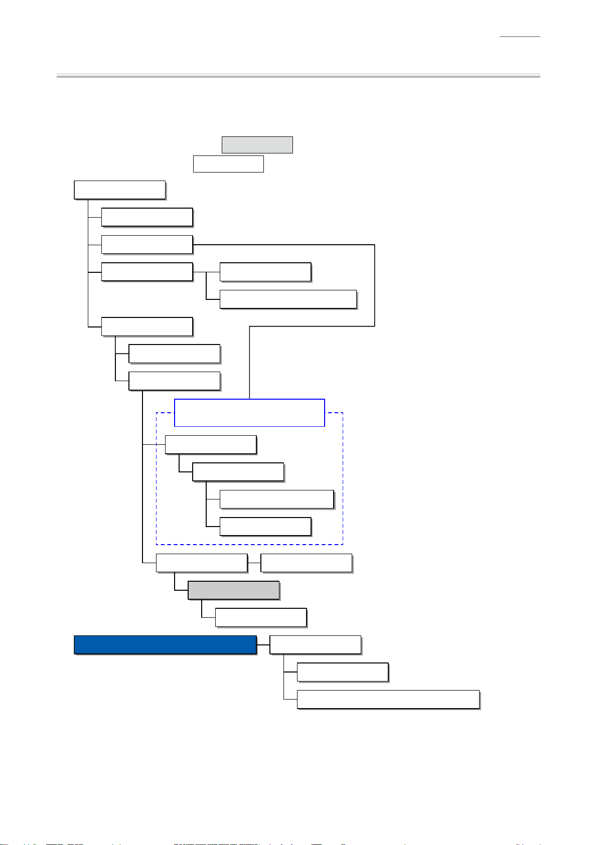
Flowchart
NOTE: Some of the major components may be removed/replaced without removing the piano
unit from the stand. Remove the piano unit from the stand as necessary according to
the work environment and with due consideration for safety.
NOTE: Parts indicated with a Gray Box must be removed when disassembling the parts
indicated with a
Assembled Product
A. Pedal Unit
B. Stand
E. BOX/PCB
C. TOP BOARD UNIT
N. SPEAKER
D. KEY COVER UNIT
White Box in the following step.
F. PCB UNIT/MAIN
G. PCB UNIT/POWER & AMP
The piano unit must be removed from
the stand when performing a repair.
J. SIDE BOARD
K. SIDE RACK UNIT
L. FRONT BOARD UNIT
M. PCB UNIT/HPA1
H. Console Unit I. PCB UNIT/CNA
E. BOX/PCB
O. KEYBOARD UNIT
DISASSEMBLY OF THE KEYBOARD UNIT
A. KEY
B. HAMMER
C. PCB UNIT/KY AND RUBBER CONTACT
– 10 –
Page 13

Disassembly Procedure
A. Remove the Pedal Unit
A-1. Disconnect the plug for pedal unit from the pedal connector.
Plug for pedal unit
Clip
AP-250
A-2. Undo six screws on the back surface.
A-3. Undo four screws.
– 11 –
Page 14

A-4. Remove the PEDAL BOARD UNIT.
NOTE: The piano unit and stand become slightly unstable when the PEDAL BOARD UNIT is
removed. Use caution so that the piano unit doesn't fall or the stand doesn't fall over.
PEDAL BOARD UNIT
A-5. Turn the ADJUSTER to remove it.
ADJUSTER
AP-250
<Caution When Completing Repair>
• Be sure to adjust the ADJUSTER height.
NOTE: The pedal unit may be damaged if the pedal is operated without height adjustment.
– 12 –
Page 15

A-6. Undo eight screws and then remove the PEDAL UNIT.
PEDAL UNIT
<Notes on Assembly>
• Tighten the screws for the PEDAL UNIT in the order of the numbers shown below.
AP-250
7 8
3
21
65
4
– 13 –
Page 16

AP-250
B. Remove the Stand
NOTE: Disassembling or assembling the stand must be done by two or more people.
NOTE: When disassembling or assembling, take precautions, such as closing the key cover and tape it
closed, so as not to get a hand caught.
B-1. Disconnect the plug for pedal unit from the pedal connector.
Plug for pedal unit
Clip
B-2. Undo two screws on the bottom surface.
B-3. Placethepianounitontheoor.
NOTE: Please do so with the key cover closed.
Back surface
– 14 –
Page 17

AP-250
B-4. Undo eight screws on the back surface and then remove the BACK BOARD.
NOTE: There are two types of screws. Be sure to use the correct screw when assembling.
BACK BOARD
B-5. Undo four screws and then remove the SIDE BOARD UNIT/LEFT, SIDE BOARD UNIT/RIGHT, and
PEDAL BOARD UNIT.
SIDE BOARD UNIT/RIGHT
SIDE BOARD UNIT/LEFT
PEDAL BOARD UNIT
– 15 –
Page 18

C. Remove the TOP BOARD UNIT
C-1. Undo three screws on the back surface.
C-2. Slide the TOP BOARD UNIT to remove it.
TOP BOARD UNIT
AP-250
<Notes on Assembly>
• Assemble the TOP BOARD UNIT so that the brackets on the TOP BOARD UNIT and those on
themaincaset.
– 16 –
Page 19

AP-250
D. Remove the KEY COVER UNIT
D-1. Close the key cover.
D-2. Undo one screw and then while lightly holding the damper in place, remove the SHAFT/for KEY
COVER (with the E-RING).
NOTE:
Remove the other side in the same manner.
SHAFT/for KEY COVER
Damper
D-3. Undo two screws on the bottom surface and then remove the SUPPORT BOARD.
[NOTE]
The SUPPORT BOARD was added to the product
after the production started.
SUPPORT BOARD
D-4. While slightly lifting the rear cover of the KEY COVER UNIT, slide the KEY COVER UNIT all the
way to the rear.
KEY COVER UNIT
– 17 –
Page 20

AP-250
D-5. Check that the sliding pin on both sides of the rear cover of the KEY COVER UNIT is visible when
seen from above the rail.
Pin
D-6. Lift the rear cover of the KEY COVER UNIT and then disengage the pins from the rail.
Pin
D-7. While lifting the KEY COVER UNIT, slide the KEY COVER UNIT further toward the rear.
D-8. In the same manner as when disengaging the pins on the rear cover, disengage the pins on the
front cover from the rail and then remove the KEY COVER UNIT.
– 18 –
Page 21

AP-250
<Notes on Assembly>
• To assemble the SHAFT/for KEY COVER, slightly lift the KEY COVER UNIT while holding the
damper in place, and position the hole to insert the SHAFT/for KEY COVER.
• Align the groove on the SHAFT/for KEY COVER to that on the damper.
DamperKEY COVER UNIT
SHAFT/for KEY COVER
E. Remove the BOX/PCB
NOTE: If you perform the following steps while the piano unit is attached to the stand, use caution as
not to drop the BOX/PCB nor apply too much tension to the cables and connectors.
E-1. Undo four screws on the bottom surface.
BOX/PCB
– 19 –
Page 22

E-2. Slide the BOX/PCB to remove it.
NOTE: The BOX/PCB and piano unit are connected with cables. Use caution when removing the
BOX/PCB.
NOTE: Be sure to hold the BOX/PCB with a hand so as not to add tension to the cables and
connectors.
BOX/PCB
E-3. Disconnect six connectors and then remove the BOX/PCB.
NOTE: Releasetheconnectorlockbeforedisconnectingtheatcable.
AP-250
1
2
3
4
5
6
Type Connected From Connected To (CN No.)
Harness HPA1 PCB PSA1 PCB (CN3)
Harness Left speaker PSA1 PCB (CN9)
Harness Right speaker PSA1 PCB (CN6)
Harness CNA1 PCB MDA1 PCB (CN1)
Flat cable KYB1 PCB MDA1 PCB (CN3)
Harness Pedal connector MDA1 PCB (CN8)
– 20 –
Page 23

F. Remove the PCB UNIT/MAIN
F-1. Disconnect one connector.
F-2. UndovescrewsandthenremovethePCBUNIT/MAIN.
AP-250
PCB UNIT/POWER & AMP
(PSA1 PCB)
Connector
PCB UNIT/MAIN
(MDA1 PCB)
<Notes on Assembly>
• Connect the connector for the PSA1 PCB before assembling the MDA1 PCB to the BOX/PCB.
Connector
– 21 –
Page 24

G. Remove the PCB UNIT/POWER & AMP
G-1. Disconnect one connector.
G-2. Undo six screws and then remove the PCB UNIT/POWER & AMP.
AP-250
PCB UNIT/POWER & AMP
(PSA1 PCB)
Connector
PCB UNIT/MAIN
(MDA1 PCB)
<Notes on Assembly>
• Connect the connector for the PSA1 PCB with the MDA1 PCB removed.
Connector
– 22 –
Page 25

H. Remove the Console Unit
H-1. Disconnect the connector for CNA1 PCB from the BOX/PCB.
NOTE: Please refer to the “E. Remove the BOX/PCB”.
H-2. Undo nine screws.
NOTE: The center bracket is screwed at a different hole position from the other brackets.
CENTER OTHEROTHER
AP-250
H-3. Lift the console unit until it warps slightly. While maintaining this state, disengage the joint of the
SIDE RACK UNIT and console unit on one side.
NOTE: Do not apply too much force. Doing so may damage the digital piano.
NOTE: Be careful not to damage the KEY FELT.
SIDE RACK UNIT
Console unitKEY FELT
– 23 –
Page 26

H-4. Disengage the joint on the other side and remove the console unit.
Cut off any excess material
Console unit
<Caution When Replacing With New Parts>
• Attach the KEY FELT as shown below.
KEY FELT
2 ~ 4 mm 2 ~ 4 mm
AP-250
1 ± 0.5 mm
FABRIC TAPE/10X42 FABRIC TAPE/10X42CONSOLE PANEL/LEFT & RIGHT
– 24 –
Page 27

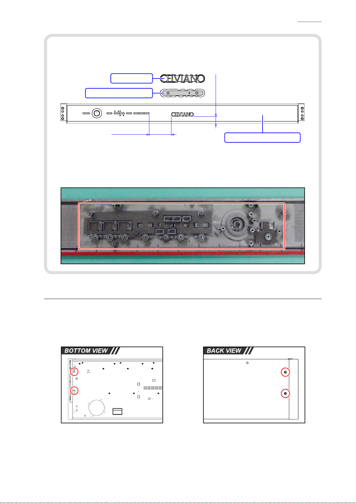
I. Remove the PCB UNIT/CNA
NOTE: The PCB UNIT/CNA consists of the CNA1 PCB and CNA2 PCB.
I-1. Undo four screws and then remove two PLASTIC BRACKET.
PLASTIC BRACKET
I-2. Undo 13 screws and then remove the PCB UNIT/CNA.
AP-250
PCB UNIT/CNA
CNA2 PCBCNA1 PCB
– 25 –
Page 28
AP-250
<Caution When Replacing With New Parts>
• A new CONSOLE PANEL/MIDDLE does not come with the NAME PLATE. When replacing the
CONSOLE PANEL/MIDDLE, attach the NAME PLATE with the DOUBLE FACED TAPE.
NAME PLATE
DOUBLE FACED TAPE
76.5 ± 2 mm
24.0 ± 2 mm
CONSOLE PANEL/MIDDLE
<Notes on Assembly>
• Before assembling the PCB UNIT/CNA, check that the KNOB/for ROTARY, TACT BUTTON,
LED COVER, LED SPACER, and FABRIC SHEET have been assembled to the CONSOLE
PANEL/MIDDLE.
J. Remove the SIDE BOARD
NOTE: The basic procedure to remove the part is the same on both sides.
J-1. Undo two screws on the bottom surface.
J-2. Undo two screws on the back surface.
– 26 –
Page 29

J-3. Undo two screws and then remove the BRACKET.
J-4. Undo three screws.
SIDE RACK UNIT SIDE BOARD
BRACKET
J-5. Remove the SCREW CAP and then undo one screw.
NOTE: The SCREW CAP is secured with the DOUBLE FACED TAPE.
AP-250
SCREW CAP
J-6. Remove the SIDE BOARD.
– 27 –
Page 30

K. Remove the SIDE RACK UNIT
NOTE: The basic procedure to remove the part is the same on both sides.
K-1. Undo two screws on the bottom surface.
K-2. Undo one screw.
SIDE RACK UNIT
AP-250
Console unit
K-3. Undo one screw on the side surface and then remove the SIDE RACK UNIT and SIDE BLOCK.
SIDE RACK UNIT SIDE BLOCK SIDE RACK UNIT
– 28 –
Page 31

K-4. Undo two screws and then remove the SIDE BLOCK from the SIDE RACK UNIT.
SIDE RACK UNIT
SIDE BLOCK
K-5. Remove the RUBBER FOOT.
RUBBER FOOT
AP-250
– 29 –
Page 32

L. Remove the FRONT BOARD UNIT
L-1. Disconnect the connector for HPA1 PCB from the BOX/PCB.
NOTE: Please refer to the “E. Remove the BOX/PCB”.
L-2. Undo six screws on the bottom surface and then remove the FRONT BOARD UNIT.
AP-250
FRONT BOARD UNIT
– 30 –
Page 33

M. Remove the PCB UNIT/HPA1
M-1. Disconnect the connector for HPA1 PCB from the BOX/PCB.
NOTE: Please refer to the “E. Remove the BOX/PCB”.
M-2. Undo two screws and then remove the PCB UNIT/HPA1.
PCB UNIT/HPA1
<Caution When Replacing With New Parts>
AP-250
• Mount the LED as shown below while paying attention to the polarity.
25.1 ± 0.3 mm
D1
N. Remove the SPEAKER
NOTE: The basic procedure to remove the part is the same on both sides.
N-1. To replace the harness for the speaker, disconnect the speaker connector from the BOX/PCB.
NOTE: Please refer to the “E. Remove the BOX/PCB”.
N-2. Undo two screws and then remove the COVER NET.
COVER NET
– 31 –
Page 34

N-3. Unsolder the harness.
N-4. Undo four screws and then remove the SPEAKER and SPEAKER NET.
<Left speaker> <Right speaker>
AP-250
Positive terminal (Red)
Negative terminal (Black)
Negative terminal (White)
Positive terminal (Red)
SPEAKER NETSPEAEKER
<Notes on Assembly>
• The SPEAKER NET has front and back faces. Face the smooth surface to the bottom when
assembling.
– 32 –
Page 35

O. Remove the KEYBOARD UNIT
O-1. Undo 15 screws and then remove seven PLASTIC BASE.
NOTE: The PLASTIC BASE at the center and the both ends are screwed at different hole
positions from the others.
AP-250
O-2. Undo three screws.
CENTER
OTHEROTHERLEFT RIGHT
– 33 –
Page 36

O-3. Undo 19 screws on the bottom surface and then remove the KEYBOARD UNIT.
KEYBOARD UNIT
AP-250
– 34 –
Page 37

7 mm
Disassembly of the KEYBOARD UNIT
A. Remove the KEY
<Removing the Keys>
• To remove the keys, you will need two of the tools described below.
• Beforeremovingablackkey,youmustrstremovebothwhitekeysoneithersideoftheblack
key.
• White keys may be removed with the same procedures as removing black keys.
<Tool>
• The tool used in the photos in this section was converted from a gardening ID tag. The size and
shape of an ID tag accord to the dimensions below.
<Note on Shaping an ID Tag>
• The thickness of the tool must be within 1.2 ~ 1.3 mm. If the tool is too thin, removing keys
becomedifcult.Ifthetoolistoothick,itmaydamagetheribofthechassis.
AP-250
<Tool Dimensions>
Width:
15~20 mm
Thickness:
within 1.2~1.3 mm
R=2.75 mm
Use this part to
remove the key.
– 35 –
Page 38

A-1. Undo 12 screws and then remove four KEY SPACER.
NOTE: There are four types of the KEY SPACER. Be sure to use the correct type when
assembling.
KEY SPACER/A KEY SPACER/B KEY SPACER/C KEY SPACER/D
AP-250
KEY SPACER/A
KEY SPACER/B
KEY SPACER/C
KEY SPACER/D
<How to Identify KEY SPACER>
• ThereisanidenticationmarkingontheupperrightorupperleftoftheKEYSPACER.
Parts Name Marking
KEY SPACER/A SPC-A
KEY SPACER/B SPC-B
KEY SPACER/C SPC-C
KEY SPACER/D SPC-D
– 36 –
Page 39

A-2. Insert the two tools between the rib of the chassis and a key and then remove the key.
NOTE: Whenyouinsertthetoolstoacertainextent,thelatchwhichxingthekeyisdisengaged
and the keys are lifted for removal.
Tools
Chassis
<Cross-section Image>
AP-250
Tool
KEYRib of the chassis
– 37 –
Page 40

<Reference: Musical Scale>
Left end Right end
• The scale shown below is used for the piano.
Scale
Note
C
(Do)
D
(Re)
E
(Mi)
(Fa)
F
G
(So)
A
(La)
AP-250
B
(Ti)
SA
B C D E F G A B C D E F G A B C D E F G A B
(A)
<Keyboard Layout>
• Refer to the illustration on the right and install the white keys in
the correct order of the note.
NOTE: A note is marked at the upper end of each key. You
may ignore the number marked after the note.
NOTE:
NOTE:
• All black keys are identical; therefore, they may be installed in
any order
The parts for the keys at both ends and the second
one from the left end dif
fer from the other keys with the
same notes.
InstallthekeysintheorderofC→D→E→F→G
→A→Bintherangemarkedwitharedbrokenlinein
the illustration (the range between the third key from
the left end and the second key from the right end).
.
C D E F G A B C D E F G A B C D E F G A B C D E F G A B SC
Note
D F ASA B
SA
B C D E F G A B SC
BE GC
(C)
SC
– 38 –
Page 41

<Caution When Replacing With New Parts>
• A set of new white keys consists of the parts below.
NOTE: Remove the part indicated with a red line before use.
NOTE: The parts for the keys at both ends and the second one from the left end differ from
the other keys with the same notes.
Parts Name Note Remarks
WHITE KEY/SA SA (A) Designated for the left end
1
WHITE KEY/B B Designated for the second key from the left end
2
WHITE KEY/CEGB C/E/G/B A set of C/E/G/B
3
WHITE KEY/DFA D/F/A A set of D/F/A
4
WHITE KEY/SC SC (C) Designated for the right end
5
AP-250
BE GC
D F ASA B
SC
– 39 –
Page 42

<Applying Grease>
• Apply grease on the guide for keys as necessary after the keys are replaced.
NOTE: Apply grease on the side of the guide for keys.
Code No. Parts Name Specication
94816509 SLICONE GREASE G-501.80G-PC
Guide for black key
AP-250
Guide for white key
Guide for white key
Apply grease here
(In the area indicated in green)
Guide for black key
Apply grease here
(In the area indicated in green)
– 40 –
Page 43

<Installing the Keys>
Fit securely into the chassis.
• Follow the steps below to install the white and black keys.
NOTE: Thewhitekeysmustbearrangedinaspecicorder.Installthemaccordingtothe
correct order of the note. Be sure to install the white key at a hammer for a white key.
AP-250
NOTE:
(1)
(2)
(3) Press the key and check to see if it moves properly
Install a black key before installing the white keys on its sides. Be sure to install the
black key at a hammer for a black key
Assemble a key to a hammer
Pressthekeytottheholeofthekeywiththeprotrusionofthechassis.
Assemble a key to a hammer.
.
.
.
<Locations to Install the White and Black Keys>
• Install a white key in the position of a guide for white key.
• Install a black key in the position of a guide for black key.
Guide for black key
Guide for white key
– 41 –
Page 44

B. Remove the HAMMER
Tweezers
B-1. Place the chassis upside down so that the hammers are visible.
<Identifying the Hammers When Placed Upside Down>
• The size chassis hole differs between white and black keys. The hammer for a black key goes
into a bigger hole, while the hammer for a white key goes into a smaller hole.
Hammer for white key Hammer for black key
B-2. Press the chassis with the tip of tweezers.
AP-250
B-3. While catching a hammer with tweezers, set the tweezers against the resin part of the chassis.
B-4. Using the chassis-tweezer contact as a fulcrum point, press down against the resin part in the
direction of the red arrow shown below, and then disengage the hammer.
NOTE: You must press the resin part of the hammer. Pressing on the metal part of the hammer
may damage the area connected to the resin.
NOTE: If a hammer does not disengage easily, perform the steps while lifting the hammer.
Press down the resin part.
Fulcrum point
– 42 –
Page 45

<Kinds of Hammers>
Type of Hammer (for a white key)
<Hammers for black keys>
• Thereareseveralkindsofhammers.Thetypeofahammermaybeidentiedbythecode
engraved on it.
Type of Hammer: “W” for a white key, “B” for a black key.
Hammer Code: The hammers for white keys are coded W1, W2, W3, and W4.
The hammers for black keys are coded B1, B2, B3, and W4.
Hammer Code (for a white key)
AP-250
Type of Hammer (for a black key)
Hammer Code (for a black key)
<Location to Install the Hammers>
• A hammer must be installed at the correct location according to its type. The combination of
hammers and keys are shown below.
B1 (9 keys) B2 (9 keys) B3 (9 keys) B4 (9 keys)
W1 (13 keys)
W2 (13 keys)
<Hammers for white keys>
– 43 –
W3 (13 keys) W4 (13 keys)
Page 46

<Installing the Hammers>
Tweezers
• Follow the steps below to install the hammers for white and black keys.
NOTE: Thehammersmustbearrangedinaspecicorder.Installthemaccordingtothe
correct order.
AP-250
NOTE:
(1)
(2) Press the chassis with the tip of tweezers.
(3) Using the chassis-tweezers contact as a fulcrum point, press down the metal part of the
If a hammer does not move smoothly
location.
Use the tweezers to set a hammer at its correct location.
hammer in the direction of the red arrow shown below
NOTE:
Be careful not to damage the felt.
Press down against the metal part.
, check to see if it is installed at the correct
, and then install the hammer.
Locked at this point
Fulcrum point
Be careful not to damage the felt.
– 44 –
Page 47

AP-250
C. Remove the PCB UNIT/KY AND RUBBER CONTACT
NOTE: The PCB UNIT/KY AND RUBBER CONTACT consists of the KYA1 PCB, KYB1 PCB, and KYC1
PCB.
C-1. Release the connector lock and remove the FLAT CABLE.
C-2. Undo 23 screws and then remove the PCB UNIT/KY AND RUBBER CONTACT.
FLAT CABLE
KYA1 PCB KYB1 PCB KYC1 PCB
C-3. Remove eight RUBBER CONTACT.
NOTE: One RUBBER CONTACT differs in length.
PCB UNIT/KY AND RUBBER CONTACT
RUBBER CONTACT Short RUBBER CONTACT
RUBBER CONTACT/AG
– 45 –
RUBBER CONTACT/AC
Page 48

<Installing the PCB UNIT/KY AND RUBBER CONTACT>
• Secure the PCB UNIT/KY AND RUBBER CONTACT with 23 screws.
NOTE: Tighten the screws while pressing the PCB in the direction of the red arrow shown
below.
• Connect the FLAT CABLE to the KYB1 PCB and lock the connector.
NOTE: Insertitrmlyandlockup.
AP-250
FLAT CABLE
<How to Install RUBBER CONTACT>
• LightlyinsertthetipofaRUBBERCONTACTintothePCBrst,andthenpressitinusingthe
end of a paper clip.
NOTE: Do not press with too much force. Doing so may damage the RUBBER CONTACT.
– 46 –
Page 49

Test Items / Flowchart
Start
“FUNCTION” + “SONG” + “RECORDER” + POWER ON
Start the Diagnostic Program
(Flash Sum Check / LED Check)
“FUNCTION” × 2
Model Check
“FUNCTION”
ROM Version Check
“FUNCTION” × 2
AP-250
DIAGNOSTIC PROGRAM
Button Check / Pedal Check
“FUNCTION” × 2
Keyboard Check /
Speaker Polarity Check
“FUNCTION”
USB Check
“FUNCTION”
RAM Check
“FUNCTION” *Restarts in the user mode.
End the Diagnostic Program
Preparation
(1) Connect the AC adaptor.
PREPARATION: PC & USB cable
POWER OFF
(2) Connect the pedal.
(3) Adjust the main volume so that it is at about 1/3 of the full volume.
(4) Have a PC and USB cable ready.
NOTE: Please refer to the user's guide for PC system requirements.
NOTE: The “USB Check” cannot be performed without a PC and a USB cable.
– 47 –
Page 50

AP-250
A0#
C1# D1# F1# G1# A1#
C2# D2# F2# G2# A2#
C3# D3# F3# G3# A3#
C4# D4# F4# G4# A4#
C5# D5# F5# G5# A5#
C6# D6# F6# G6# A6#
C7# D7# F7# G7# A7#
Test Procedure
ADDITIONAL NOTE:
Refertothebelowforthepitchoftheconrmationorerrortoneswhichyouhearduringthetest.
A0 B0 C1 D1 E1 F1 G1 A1 B1 C2 D2 E2 F2 G2 A2 B2 C3 D3 E3 F3 G3 A3 B3 C4 D4 E4 F4 G4 A4 B4 C5 D5 E5 F5 G5 A5 B5 C6 D6 E6 F6 G6 A6 B6 C7 D7 E7 F7 G7 A7 B7 C8
A. Start the Diagnostic Program (Flash Sum Check / LED Check)
A-1. Hold down the “FUNCTION”, “SONG” and “RECORDER” buttons at the same time to turn the
power ON.
NOTE: Hold down three buttons until the diagnostic program starts.
•
Whenthediagnosticprogramstarts,allLEDsilluminatebriey.Releasethethree
buttons after the LEDs illuminate.
• The “P” (Power) LED remains ON.
NOTE: Ittakesapproximatelyvesecondsforthediagnosticprogramtostart.
<LED status during the diagnostic program startup>
– 48 –
Page 51

AP-250
A-2. Once the diagnostic program is started, the “Flash Sum Check” is performed automatically.
If the result passes (OK):
• The program automatically proceeds to the next step.
If the result fails (NG):
•
The“SONG(Left)”,“SONG(Right)”and“RECORDER”LEDsareashing.Pressthe
“FUNCTION” button to restart the digital piano in the user mode.
A-3. The “LED Check” starts automatically and the LEDs keep illuminating in the order shown below.
• Lit in Yellow: SONG (Left)
• Lit in Red: SONG (Right), RECORDER, L, R, CONCERT, MODERN, ELEC PIANO
A-4. Check that all LEDs illuminate.
B. Model Check
NOTE: To skip this check, press the “FUNCTION” button twice and proceed to the next check.
B-1. Press the “FUNCTION” button.
NOTE: Theconrmationchord(C4/E4/G4)sounds.
B-2. Press the “FUNCTION” button again.
NOTE: Themodelidenticationtone(C4)soundsimmediatelyaftertheconrmationchord(C4/
E4/G4).
B-3. CheckthatthemodelidenticationtonesoundsandalsothatthefollowingLEDisashing.
<For AP-250>
•
Modelidenticationtone:C4
• Flashing in Red: CONCERT
– 49 –
Page 52

AP-250
C. ROM Version Check
(This section describes how to identify the ROM version, not to test it.)
NOTE: To skip this check, press the “FUNCTION” button and proceed to the next check.
C-1. When you press the “FUNCTION” button, the following LEDs illuminate and the ROM Version
Check Mode enters into its stand-by status.
NOTE: Theconrmationchord(C4/E4/G4)sounds.
• Lit in Red: RECORDER, CONCERT, MODERN, ELEC PIANO
C-2. You can identify the ROM version (4 digits) by repeatedly pressing the “SONG” button while in the
stand-by status.
NOTE: The number indicating each digit of the ROM version will be expressed by LEDs that
illuminate.
NOTE: Eachtimeyoupressthe“SONG”button,theconrmationtone(C6)soundsandtheLED
indication moves to the next digit.
Stand-by status
(As in step C-1)
<Version number vs. LED indication>
Number LED Number LED
0 All LEDs OFF 6 “CONCERT” + “MODERN”
1 “ELEC PIANO”
2 “MODERN”
3 “MODERN” + “ELEC PIANO” 8 “RECORDER”
4 “CONCERT” 9 “RECORDER” + “ELEC PIANO”
5 “CONCERT” + “ELEC PIANO”
<Example>
The example below shows the ROM version “0105” (Ver. 1.05).
Stand-by status
↓
4th digit All LEDs OFF (Version number: 0)
↓
3rd digit “ELEC PIANO” (Version number: 1)
↓
2nd digit All LEDs OFF (Version number: 0)
↓
1st digit “CONCERT” + “ELEC PIANO” (Version number: 5)
“SONG” “SONG” “SONG” “SONG”
4th digit 3rd digit 2nd digit 1st digit
“CONCERT” + “MODERN” +
7
“ELEC PIANO”
– 50 –
Page 53

D. Button Check
NOTE: This check cannot be skipped.
D-1. Press the “FUNCTION” button twice.
NOTE: Theconrmationchord(C4/E4/G4)soundseachtimeyoupressthebutton.
D-2. Press the buttons in the order shown below.
If the result passes (OK):
• Theconrmationtone(C6)sounds.
• Whenpressthe“ELECPIANO”buttonattheend,theconrmationchord(C4/E4/G4)sounds.
If the result fails (NG):
• If there is a button failure or the buttons are pressed in a wrong sequence, the error tone (F2)
sounds.
AP-250
E. Pedal Check
NOTE: When you choose to skip this check, simply proceed to the next check.
E-1. Press the “SOFT” pedal and then check that the “CONCERT”
LED is lit.
NOTE: Theconrmationtone(E4)sounds.
• Lit in Red: CONCERT
SOFT DAMPER
E-2. Press the “SOSTENUTO” pedal and then check that the
“MODERN” LED is lit.
NOTE: Theconrmationtone(G4)sounds.
• Lit in Red: MODERN
E-3. Press the “DAMPER” pedal fully and then check that the “ELEC PIANO” LED is lit.
NOTE: Theconrmationtone(C4)sounds.
SOSTENUTO
• Lit in Red: ELEC PIANO
E-4. Press the “DAMPER” pedal halfway (half-pedal) and then check that the “ELEC PIANO” LED is
ashing.
NOTE: Theconrmationtone(C5)sounds.
• Flashing in Red: ELEC PIANO
– 51 –
Page 54

F. Keyboard Check
NOTE: To skip this check, press the “FUNCTION” button twice and proceed to the next check.
F-1. Press the “FUNCTION” button twice and then check that the “SONG (Left)” LED is lit.
NOTE: Theconrmationchord(C4/E4/G4)soundseachtimeyoupressthebutton.
NOTE: The LED does not illuminate if the touch response adjustment data has been reset.
Please refer to the “Resetting the Touch Response Adjustment Data” for details.
• Lit in Yellow: SONG (Left)
F-2. Press the “ELEC PIANO” button and then check that the “ELEC PIANO” LED is lit.
• Lit in Red: ELEC PIANO
AP-250
F-3. Press a key and then check that the sound comes out (sine wave) as follows.
NOTE: Check all keys.
Key Left Speaker Right Speaker Remarks
Press a key
halfway
Press a key
all the way
C6 sine wave When the contact
C6 sine wave C4 sine wave
When the contact
turned ON
G. Speaker Polarity Check
NOTE: When you choose to skip this check, simply proceed to the next check.
is turned ON
1
and 3 are
2
G-1. Press the “MODERN” button and then check that the “MODERN” LED is lit.
• Lit in Red: MODERN
G-2. Press any key and then check that the sound correctly comes out (sine wave).
NOTE: Check the sound while you are at the center of the digital piano.
– 52 –
Page 55

H. USB Check
NOTE: To skip this check, press the “FUNCTION” button and proceed to the next check.
H-1. Press the “FUNCTION” button.
NOTE: Theconrmationchord(C4/E4/G4)sounds.
H-2. Press the “CONCERT” button and then check that the “L” LED is lit.
NOTE: Theconrmationtone(F2)sounds.
• Lit in Red: L
H-3. Connect the digital piano to the PC with a USB cable.
H-4. Press the “CONCERT” button and then check that the “R” LED is lit.
NOTE: Theconrmationtone(C6)sounds.
AP-250
• Lit in Red: R
H-5. Disconnect the USB cable.
– 53 –
Page 56

AP-250
I. RAM Check
NOTE: To skip this check and end the diagnostic program, press the “FUNCTION” button twice to
restart the digital piano in the user mode.
I-1. Pressthe“FUNCTION”buttonandthencheckthatthefollowingLEDsareashing.
NOTE: Theconrmationchord(C4/E4/G4)sounds.
• Flashing in Yellow: SONG (Left)
• Flashing in Red: SONG (Right)
I-2. Press the “SONG” button to start the check. Check that the LED status changes as shown below.
NOTE: It takes approximately 15 seconds until the check ends.
During the Writing Check
“SONG (Left)” LED Lit in Yellow
“SONG (Right)” LED OFF
During the Reading Check
“SONG (Left)” LED OFF
“SONG (Right)” LED Lit in Red
The Check Complete
“SONG (Left)” LED Lit in Yellow
“SONG (Right)” LED Lit in Red
I-3. Press the “FUNCTION” button to restart the digital piano in the user mode.
<LED status during the user mode>
• Lit in Red: L, R, CONCERT
I-4. Turn the power OFF.
– 54 –
Page 57

AP-250
Resetting the Touch Response Adjustment Data
<Caution>
Be sure to reset the touch response adjustment data by following the steps below after
the main PCB or a keyboard component is replaced.
<Applicable Parts>
•Main PCB (MDA1 PCB)
•KEYBOARD UNIT
•Components for the KEYBOARD UNIT
(Refer to the EXPLODED VIEW and PART LIST: KEYBOARD UNIT)
<Reset Procedure>
(1) Hold down the “FUNCTION”, “CONCERT” and “MODERN” buttons at the same time to turn the
power ON.
NOTE: Hold down three buttons until the reset mode starts.
• When the reset mode starts, all LEDs illuminate. Release the three buttons after the LEDs
illuminate.
• The “P” (Power) LED remains ON.
<LED status during the reset mode startup>
(2) Press the “SONG” button and then check that the following LEDs are lit.
• Lit in Red: L, R
– 55 –
Page 58

(3) Press the “METRONOME” button and then check that the following LEDs are lit.
• Lit in Red: R, ELEC PIANO
(4) Press the “ELEC PIANO” button and then check that the following LEDs are lit.
• Lit in Yellow: SONG (Left)
• Lit in Red: RECORDER, R, ELEC PIANO
(5) Press the “RECORDER” and “METRONOME” buttons at the same time to start resetting.
AP-250
(6) When resetting is complete, the digital piano restarts in the user mode.
<LED status during the user mode>
(7) Turn the power OFF.
NOTE: After resetting is complete, perform the “KEYBOARD CHECK” in the diagnostic program
and then check that the touch response adjustment data has been reset. Please refer to
the “DIAGNOSTIC PROGRAM” for details.
– 56 –
Page 59

TOP BOARD & CONSOLE UNIT
6
AP-250
EXPLODED VIEW
9
8
12
16
9
8
Detail A (Both side)
10
7
Detail B (Both side)
11
15
17
18
BUTTON AREA
19
25
24
20
23
14
28
13
27
21
22
28
17
26
30
– 57 –
29
3
31
32
Page 60

KEYBOARD UNIT
AP-250
33
38
39
36
40
43
35
41
42
44
47
48
45
46
53
34
49
50
37
51
5
54
52
56
55
– 58 –
Detail A
59
60
58
57 56
58 55
57
Page 61

AP-250
MAIN CASE UNIT
62
64
61
67
63
65
* Added to the product
after the production
started.
66
67-1
67-3
KEYBOARD UNIT
63
64
67
67-2
74
79
Detail B
78
70
CNA1 & Harness
61
80
69
71
73
81
70
71
80
68
74
77
72
Detail A (Both side)
75
76
74
4
– 59 –
81
82
1
2
83
84
Page 62

AP-250
STAND
85
86
87
88
89
88
91
93
90
92
94
– 60 –
Page 63

PARTS LIST
AP-250
AP-250
Notes:
1. Pricesandspecicationsaresubjecttochange
withoutpriornotice.
2. Refertothelatest“PartsPriceCode”at
“PARTSFINDER”ontheCasioServiceWEBsite
(https://www.servicecasio.com).
3. Asforsparepartsorderandsupply,referto
the“GUIDEBOOKforSparePartsSupply”,
publishedseparately.
4. Thenumbersinitemcolumncorrespondto
thesamenumbersindrawing.
– 61 –
Page 64

AP-250
11111111AMDA1
y
1: AP-250_BLACK_DI
2: AP-250_BLACK_EU
3: AP-250_BLACK_UK
4: AP-250_BLACK_US
MAIN PCB
N 1 10433618 PCB UNIT/MAIN TK-RJM512378*002
CN13 10236624 CONNECTOR/USB UBR24-4K5G00 11111111C
IC2
N IC3,IC4 10427243 IC BD00IA5WEFJ-E2 22222222X
N IC6 10431989 IC WM8740SEDS/RV 11111111X
N IC7 10422005 IC SN74LVC1G123DCTR 11111111X
IC10 10375074 IC XC6404FY52PR-G 11111111X
IC11 10430187 IC XC6701D902PR-G 11111111X
IC12,IC14 10211950 IC NJM2068M-D(TE1) 22222222X
N IC13 10430918 IC BD3464FV-E2 11111111X
Q1,Q7-Q9,Q14-Q16 10402605 TRANSISTOR DSA500100L 77777777X
Q2-Q6,Q10,Q11 10399706 TRANSISTOR DSC500100L 77777777X
D1-D3 10009218 DIODE 1SS400TE61 33333333X
L25 10193074 COIL DLW21HN181SQ2L 11111111X
X1 10431923 RESONATOR 7V22580001 11111111X
X2 10375016 RESONATOR 7V48080006 11111111X
N 2 10433594 PCB UNIT/POWER & AMP TK-RJM512379*001 11111111BPSA1
J2 10334294 JACK/DC KM02022ABMP 11111111A
IC1 10306512 IC TDA7297 11111111X
IC2 10375029 IC LA5756-MDB-E 11111111X
IC3 10430186 IC XC8102AA01MR-G 11111111X
IC4 10430185 IC XC6701BC02PR-G 11111111X
IC5 10430184 IC XC6701B502PR-G 11111111X
IC6 10430183 IC XC6216D332PR-G 11111111X
IC7 10306415 IC BH3547F-E2 11111111X
Q1,Q2,Q10,Q11,
Q20,Q21,Q25
D1 10294394 DIODE SK34A 11111111X
D10 10430929 DIODE DB2X41400L 11111111X
D20 10073815 DIODE UDZSTE-178.2B 11111111X
L1,L10,L11 10231920 COIL RB53-856397NP 33333333X
L20 10232457 COIL RII7-860400NP 11111111X
10429820 LSI/MEMORY TC58NVG0S3ETA00B3H 1 1 1 1 1 1 1 1 C
POWER & AMP PCB
10399706 TRANSISTOR DSC500100L 77777777X
5: AP-250_BROWN_DI
6: AP-250_BROWN_EU
7: AP-250_BROWN_UK
8: AP-250_BROWN_US
Q't
12345678
R RemarksN Item Code No. Parts Name Specification
– 62 –
Page 65

AP-250
y
11111111CCNA1/CNA2
11111111BMain volume
11111111CHPA1
11111111XPower lamp
11111111Xfor NAME PLATE
1: AP-250_BLACK_DI
2: AP-250_BLACK_EU
3: AP-250_BLACK_UK
4: AP-250_BLACK_US
CNA PCB & HPA1 PCB
N 3 10433563 PCB UNIT/CNA TK-RJM512320*002
D601,D603-D609 10336974 LED 26-21/R1 88888888X
D602 10336975 LED 26-21/Y1 11111111X
D610-D612 23901820 DIODE 1SS355TE-17 33333333X
SW601-SW608 10337110 SWITCH TP-1138A-10-100GF 88888888X
VR601 10399354 VARIABLE RESISTOR F-09KH1-CASIO-2
N 4 10433603 PCB UNIT/HPA1 TK-RJM512381*001
D1 10203050 LED 231XHD
J701,J702 10132088 JACK/PHONE JY-6360*01-070 22222222B
L701,L702 10231919 COIL RB53-856396NP 22222222X
KEYBOARD PCB
N 5 10437588 PCB UNIT/KY and RUBBER CONTACT TK-RJM512336*002 11111111CKYA1/KYB1/KYC1
D1-D46 10301580 DIODE LM1MA142WAT1G 46 46 46 46 46 46 46 46 X
Q101-Q364 69300298 TRANSISTOR 2SC4081T106R 264 264 264 264 264 264 264 264 X
TOP BOARD & CONSOLE UNIT
N 6 10433619 TOP BOARD UNIT TK-RJM512086*001 1111 X
N 6 10433620 TOP BOARD UNIT TK-RJM512086*002 1111X
N 7 10433564 KEY COVER UNIT TK-RJM511862*001 1111 C
N 7 10433565 KEY COVER UNIT TK-RJM511862*002 1111C
N 8 10431988 SHAFT/for KEY COVER RJM512131-001V01 22222222X
N 9 10232237 E RING R-ER-4Z3BL 22222222X
N 10 10428382 SLIDE CAP/B RJM512241-001V01 22222222X
11 10211851 SLIDE CAP RJM505899-001V01 22222222X
N 12 10428359 PLASTIC BRACKET RJM511973-001V01 77777777X
N 13 10428364 NAME PLATE RJM511986-001V01 11111111X
14 10305053 DOUBLE FACED TAPE RJM507535-001V02
N 15 10427192 CONSOLE PANEL/LEFT RJM511903-001V01 11111111X
N 16 10427193 CONSOLE PANEL/RIGHT RJM511904-001V01 11111111X
N 17 69239090 FABRIC TAPE/10X42 M440240-1 22222222X
18 10337938 KEY FELT RJM509922-001V01 11111111X
N 19 10431918 CONSOLE PANEL/MIDDLE RJM512018-002V01 11111111X
20 10337054 LED COVER RJM509410-001V01 33333333X
21 10428304 LED COVER RJM512166-001V01 22222222X
22 10428263 LED SPACER/A RJM512126-001V01 22222222X
5: AP-250_BROWN_DI
6: AP-250_BROWN_EU
7: AP-250_BROWN_UK
8: AP-250_BROWN_US
Q't
12345678
R RemarksN Item Code No. Parts Name Specification
– 63 –
Page 66

AP-250
y
1: AP-250_BLACK_DI
2: AP-250_BLACK_EU
3: AP-250_BLACK_UK
4: AP-250_BLACK_US
23 10428264 LED SPACER/B RJM512127-001V01 11111111X
24 10428362 KNOB/for ROTARY RJM512136-001V01 11111111C
25 10342127 TACT BUTTON/A RJM509408-002V01 11111111X
26 10431933 TACT BUTTON/A RJM509408-004V01 11111111X
27 10337029 TACT BUTTON/B RJM509396-001V01 11111111X
28 10337030 TACT BUTTON/B RJM509396-002V01 22222222X
29 10433684 FABRIC SHEET/A RJM512456-001V01 11111111X
30 10450096 FABRIC SHEET/B RJM512457-003V02 11111111X
N 31 10436783 FABRIC TAPE/10X42 M440240-003V01 11111111X
N 32 10439051 FABRIC TAPE/5X30 M440583-004V01 11111111X
KEYBOARD UNIT
N 33 10438926 KEYBOARD UNIT TK-RJM512338*002 11111111C
N 34 10438901 BLACK KEY RJM512637*002V01 36 36 36 36 36 36 36 36 B
N 35 10437155 WHITE KEY/SA RJM512040-002V02 11111111X
N 36 10437154 WHITE KEY/B RJM512039-002V02 11111111X
N 37 10437152 WHITE KEY/CEGB RJM512037-002V02 77777777B
N 38 10437153 WHITE KEY/DFA RJM512038-002V02 77777777B
N 39 10437156 WHITE KEY/SC RJM512041-002V02 11111111X
40 10341062 HAMMER UNIT/W1 TK-RJM509600*001 13 13 13 13 13 13 13 13 C
41 10341063 HAMMER UNIT/W2 TK-RJM509601*001 13 13 13 13 13 13 13 13 C
42 10341064 HAMMER UNIT/W3 TK-RJM509602*001 13 13 13 13 13 13 13 13 C
43 10341065 HAMMER UNIT/W4 TK-RJM509603*001 13 13 13 13 13 13 13 13 C
44 10341066 HAMMER UNIT/B1 TK-RJM509604*001 99999999C
45 10341067 HAMMER UNIT/B2 TK-RJM509605*001 99999999C
46 10341068 HAMMER UNIT/B3 TK-RJM509606*001 99999999C
47 10341069 HAMMER UNIT/B4 TK-RJM509607*001 99999999C
48 10427355 KEY SPACER/A RJM512181-001V01 11111111X
49 10427356 KEY SPACER/B RJM512182-001V01 11111111X
50 10427357 KEY SPACER/C RJM512183-001V01 11111111X
51 10427358 KEY SPACER/D RJM512184-001V01 11111111X
52 37195442 FLAT CABLE N30315B1B05-UL2896 11111111X
N 53 10437576 RUBBER CONTACT/AG RJM512163-002V02 77777777B
54 10431698 RUBBER CONTACT/AC RJM512164-001V01 11111111C
55 10398226 FELT/LOWER LIMIT/BLACK KEY RJM510067-002V02 11111111X
56 10398227 FELT/LOWER LIMIT/WHITE KEY RJM503562-002V02 11111111X
57 10398219 FELT/UPPER LIMIT/HAMMER RJM511203-001V01 11111111X
5: AP-250_BROWN_DI
6: AP-250_BROWN_EU
7: AP-250_BROWN_UK
8: AP-250_BROWN_US
Q't
12345678
R RemarksN Item Code No. Parts Name Specification
– 64 –
Page 67

AP-250
y
11111111Xfor Left s
11111111Xfor Right s
1: AP-250_BLACK_DI
2: AP-250_BLACK_EU
3: AP-250_BLACK_UK
4: AP-250_BLACK_US
58 10294093 FELT/LOWER LIMIT/HAMMER TK-RJM507910*001 11111111X
59 10388000 PLATE RJM510952-001V01 11111111X
60 10343387 FABRIC TAPE/ACP RJM510100-001V01 11111111X
MAIN CASE UNIT
61 10047599 FABRIC TAPE/10X100 M440710-1 11111111X
N 62 10428360 PLASTIC BASE RJM512102-001V01 77777777X
N 63 10431987 COVER NET RJM511985-001V01 22222222X
N 64 10474441 SPEAKER CJ12FH01 22222222X
N 65 10433023 CABLE HARNESS EF-EH2P060M922
66 10432675 CABLE HARNESS EF-EH2P065M922
67 10294355 SPEAKER NET RJM508336-001V01 22222222X
N 67-1 10436098 FABRIC TAPE/15X40 RJM512618-001V01 22222222X
N 67-2 10469354 SUPPORT BOARD RJM513244-001V01 11111111X
N 67-3 10428640 BRACKET RJM512101-001V01 11111111X
N 68 10433608 SIDE BOARD/LEFT TK-RJM511946*001 1111 X
N 68 10433610 SIDE BOARD/LEFT TK-RJM511946*002 1111X
N 69 10433609 SIDE BOARD/RIGHT TK-RJM511947*001 1111 X
N 69 10433617 SIDE BOARD/RIGHT TK-RJM511947*002 1111X
N 70 10429841 BRACKET RJM512118-001V01 22222222X
N 71 10299259 PACKING RJM508522-001V01 22222222X
N 72 10433589 SIDE RACK UNIT/LEFT TK-RJM511881*001 11111111X
N 73 10433591 SIDE RACK UNIT/RIGHT TK-RJM511882*001 11111111X
N 74 10427677 SCREW CAP RJM512119-001V01 22222222X
N 75 69235860 FABRIC TAPE/3X10 M440216-1 22222222X
N 76 10442262 DOUBLE FACED TAPE RJM512682-001V01 22222222X
N 77 10427360 SIDE BLOCK/LEFT RJM511965-001V01 11111111X
N 78 10427361 SIDE BLOCK/RIGHT RJM511966-001V01 11111111X
N 79 10432627 CABLE HARNESS EF-SMP5P053M923 11111111Xfor Pedal connector
N 80 10285212 DOWEL RJM508233-001V01 22222222X
N 81 10430891 RUBBER FOOT RJM512247-001V01 22222222X
N 82 10433558 FRONT BOARD UNIT TK-RJM511884*001 1111 X
N 82 10433559 FRONT BOARD UNIT TK-RJM511884*002 1111X
N 83 10427678 BOX/PCB RJM511899-001V01 11111111X
N 84 10430888 LABEL/RATING RJM504373-080V02 1111 X
N 84 10432476 LABEL/RATING RJM504373-081V02 1111X
5: AP-250_BROWN_DI
6: AP-250_BROWN_EU
7: AP-250_BROWN_UK
8: AP-250_BROWN_US
Q't
12345678
R RemarksN Item Code No. Parts Name Specification
peaker
peaker
– 65 –
Page 68

AP-250
y
11111111Xfor P
1: AP-250_BLACK_DI
2: AP-250_BLACK_EU
3: AP-250_BLACK_UK
4: AP-250_BLACK_US
STAND
N 85 10431965 BACK BOARD RJM512032-001V01 11111111X
N 86 10433621 SIDE BOARD UNIT/LEFT TK-RJM512281*001 1111 X
N 86 10433614 SIDE BOARD UNIT/LEFT TK-RJM512281*002 1111X
N 87 10433611 SIDE BOARD UNIT/RIGHT TK-RJM512282*001 1111 X
N 87 10433615 SIDE BOARD UNIT/RIGHT TK-RJM512282*002 1111X
88 10348901 FOOT TK-RJM508370*003 1111 X
88 10348902 FOOT TK-RJM508370*004 1111X
N 89 10433612 PEDAL BOARD UNIT TK-RJM511855*001 1111 X
N 89 10433622 PEDAL BOARD UNIT TK-RJM511855*002 1111X
N 90 10433626 PEDAL BOARD TK-RJM511873*001 1111 X
N 90 10433616 PEDAL BOARD TK-RJM511873*002 1111X
91 10263906 PEDAL UNIT TK-RJM507377*001 11111111X
92 10339497 CABLE HARNESS EF-SMR5P155MP5
93 10260690 ADJUSTER FL-20-CR3-KE 11111111X
N 94 10433624 SCREW SET TK-RJM511859*001 1111 X
N 94 10433625 SCREW SET TK-RJM511859*002 1111X
ACCESSORIES
N - 10433613 STAND/MUSIC TK-RJM511858*001 1111 C
N - 10433623 STAND/MUSIC TK-RJM511858*002 1111C
- 10430927 AC ADAPTOR AD-A12150LW-F3B 11111111Bwithout AC CORD
- 10361066 AC CORD UC2LT-M006A 1 1 1 1 X US type plug
- 10361067 AC CORD EC2LT-M002A 1 1 1 1 X EU type plug
- 10361068 AC CORD KC2LT-M002A 1 1 X Korea type plug
- 10361069 AC CORD AUC2LT-M002A 1 1 X Australia type plug
- 10361070 AC CORD BC2LT-M002A 1 1 X UK type plug
N - 10399509 SEAT/CHAIR MX-CH4D(SEAT)-B 1 1 X
- 10375602 FOOT/CHAIR MX-CH4D(FOOT) 4 4 X
N - 10399508 SEAT/CHAIR MX-CH4B(SEAT)-B 1 1 X
- 10337892 FOOT/CHAIR MX-CH4B(FOOT) 4 4 X
5: AP-250_BROWN_DI
6: AP-250_BROWN_EU
7: AP-250_BROWN_UK
8: AP-250_BROWN_US
Q't
12345678
R RemarksN Item Code No. Parts Name Specification
edal unit
– 66 –
Page 69

MAIN PCB: M920-MDA1 (1/2)
(to CNA1/
CN601)
AP-250
SCHEMATIC DIAGRAMS
(to KYB1/CN803)
USB
(CN13)
(to Pedal Connector)
Not used
– 67 –
Page 70

MAIN PCB: M920-MDA1 (2/2)
(to PSA1/
CN1)
AP-250
– 68 –
Not used
Page 71

POWER & AMP PCB: M920-PSA1
DC 12 V (J2)
AP-250
(to LEFT SPEAKER)
(to RIGHT SPEAKER)
(to HPA1/
CN701)
(to MDA1/
CN16)
Not used
LEFT SPEAKER
RIGHT SPEAKER
– 69 –
Page 72

CONSOLE PCB: M920-CNA1
(to CNA2/CN603)
AP-250
(to MDA1/CN1)
POWER SWITCH
– 70 –
Page 73

CONSOLE PCB: M920-CNA2 CONSOLE PCB: M920-HPA1
(to CNA1/CN602)
POWER LAMP
AP-250
PHONES
(J701)
PHONES
(J702)
MAIN VOL.
(VR601)
– 71 –
(to PSA1/CN3)
Not used
Page 74

PEDAL PCB: M332-PDA1 / M332-PDA2
AP-250
(to MDA1/CN8)
(to PDA2/CN3)
(to PDA1/CN2)
– 72 –
Page 75

KEYBOARD PCB: M920-KYA1
AP-250
(to KYB1/CN802)
– 73 –
Page 76

KEYBOARD PCB: M920-KYB1
AP-250
(to MDA1/CN3)
(to KYA1/CN801)
(to KYC1/CN805)
– 74 –
Page 77

KEYBOARD PCB: M920-KYC1
(to KYB1/CN804)
AP-250
– 75 –
Page 78

Ver. 1 : Nov. 2012
• Correction of the DIAGNOSTIC PROGRAM (P50)
Ver. 2 : Dec. 2012
• Correction of the DISASSEMBLY (P32)
• Correction of the PARTS LIST (P62)
Ver. 3 : Apr. 2013
• Correction of the CIRCUIT DESCRIPTION (P5)
• Correction of the PARTS LIST (P64)
Ver. 4 : Dec. 2013
• Correction of the DISASSEMBLY (P17)
• Correction of the EXPLODED VIEW (P59)
• Correction of the PARTS LIST (P65)
CASIO COMPUTER CO., LTD.
CS Technical Department
TOKYO, JAPAN
 Loading...