


39LH
Installation, Start-Up and
Service Instructions
CONTENTS
Page
SAFETY CONSIDERATIONS . . . . . . . . . . . . . . . . . . . . . . . . . . 1,2
INTRODUCTION . . . . . . . . . . . . . . . . . . . . . . . . . . . . . . . . . . . . . . 2-8
Unit Identification. . . . . . . . . . . . . . . . . . . . . . . . . . . . . . . . . . . . . . .2
PREINSTALLATION. . . . . . . . . . . . . . . . . . . . . . . . . . . . . . . . . . 9-12
Rigging . . . . . . . . . . . . . . . . . . . . . . . . . . . . . . . . . . . . . . . . . . . . . . . . .9
Suspended Units . . . . . . . . . . . . . . . . . . . . . . . . . . . . . . . . . . . . . . .9
Service Clearance . . . . . . . . . . . . . . . . . . . . . . . . . . . . . . . . . . . . . .9
Condensate Drain . . . . . . . . . . . . . . . . . . . . . . . . . . . . . . . . . . . . . .9
External Vibration Isolators. . . . . . . . . . . . . . . . . . . . . . . . . . . . .9
INSTALLATION . . . . . . . . . . . . . . . . . . . . . . . . . . . . . . . . . . . . . 13-35
Base Rail Split . . . . . . . . . . . . . . . . . . . . . . . . . . . . . . . . . . . . . . . . 13
Mixing Box . . . . . . . . . . . . . . . . . . . . . . . . . . . . . . . . . . . . . . . . . . . 14
Condensate Drain . . . . . . . . . . . . . . . . . . . . . . . . . . . . . . . . . . . . 16
Variable Frequency Drive (VFD). . . . . . . . . . . . . . . . . . . . . . . 16
Install Fan Motor. . . . . . . . . . . . . . . . . . . . . . . . . . . . . . . . . . . . . . 16
Install Sheaves on Motor and Fan Shafts . . . . . . . . . . . . . 16
Install V-Belts. . . . . . . . . . . . . . . . . . . . . . . . . . . . . . . . . . . . . . . . . 17
Water and Steam Coil Piping Recommendations . . . . . 19
Coil Freeze-Up Protection . . . . . . . . . . . . . . . . . . . . . . . . . . . . 22
Refrigerant Piping, Direct Expansion (DX) Coils . . . . . . 24
Electric Heaters. . . . . . . . . . . . . . . . . . . . . . . . . . . . . . . . . . . . . . . 31
Discharge Modification . . . . . . . . . . . . . . . . . . . . . . . . . . . . . . . 34
START-UP . . . . . . . . . . . . . . . . . . . . . . . . . . . . . . . . . . . . . . . . . . 35,36
Check List . . . . . . . . . . . . . . . . . . . . . . . . . . . . . . . . . . . . . . . . . . . . 35
SERVICE . . . . . . . . . . . . . . . . . . . . . . . . . . . . . . . . . . . . . . . . . . . 36-46
General . . . . . . . . . . . . . . . . . . . . . . . . . . . . . . . . . . . . . . . . . . . . . . . 36
Fan Motor Replacement . . . . . . . . . . . . . . . . . . . . . . . . . . . . . . 36
Coil Cleaning . . . . . . . . . . . . . . . . . . . . . . . . . . . . . . . . . . . . . . . . . 36
Winter Shutdown (Chilled Water Coil Only) . . . . . . . . . . . 36
Field-Installed Coils . . . . . . . . . . . . . . . . . . . . . . . . . . . . . . . . . . 37
Coil Removal . . . . . . . . . . . . . . . . . . . . . . . . . . . . . . . . . . . . . . . . . 37
Changing Coil Hand . . . . . . . . . . . . . . . . . . . . . . . . . . . . . . . . . . 41
Filters . . . . . . . . . . . . . . . . . . . . . . . . . . . . . . . . . . . . . . . . . . . . . . . . 42
Fan Shaft Bearing Removal. . . . . . . . . . . . . . . . . . . . . . . . . . . 43
Fan and Shaft Removal . . . . . . . . . . . . . . . . . . . . . . . . . . . . . . . 45
Lubrication . . . . . . . . . . . . . . . . . . . . . . . . . . . . . . . . . . . . . . . . . . . 45
Fan Sled Disassembly . . . . . . . . . . . . . . . . . . . . . . . . . . . . . . . . 46
METRIC CONVERSION CHART . . . . . . . . . . . . . . . . . . . . . . . 47
39LA,LB,LC,LD,LF,LG,LH03-25
Indoor Air-Handling Units
DANGER
NEVER enter an enclosed fan cabinet or reach into a unit
while the fan is running.
LOCK OPEN AND TAG the fan motor power disconnect
switch before working on a fan. Take fuses with you and
note removal on tag. Electric shock can cause personal
injury or death.
LOCK OPEN AND TAG the electric heat coil power disconnect switch before working on or near heaters.
WARNING
CHECK the assembly and component weights to be sure
that the rigging equipment can handle them safely. Note
also, the centers of gravity and any specific rigging
instructions.
CHECK for adequate ventilation so that fumes will not
migrate through ductwork to occupied spaces when welding or cutting inside air-handling unit cabinet or plenum.
WHEN STEAM CLEANING COILS be sure that the area
is clear of personnel.
DO NOT attempt to handle access covers and removable
panels on outdoor units when winds are strong or gusting
until you have sufficient help to control them. Make sure
panels are properly secured while repairs are being made to
a unit.
DO NOT remove access panel fasteners until fan is completely stopped. Pressure developed by a moving fan can
cause excessive force against the panel which can injure
personnel.
DO NOT work on dampers until their operators are
disconnected.
BE SURE that fans are properly grounded before working
on them.
SAFETY CONSIDERATIONS
Air-handling equipment is designed to provide safe and
reliable service when operated within design specifications. To
avoid injury to personnel and damage to equipment or property
when operating this equipment, use good judgment and follow
safe practices as outlined below.
Manufacturer reserves the right to discontinue, or change at any time, specifications or designs without notice and without incurring obligations.
Catalog No. 04-53390016-01 Printed in U.S.A. Form 39L-7SI Pg 1 816 3-14 Replaces: 39L-6SI
WARNING
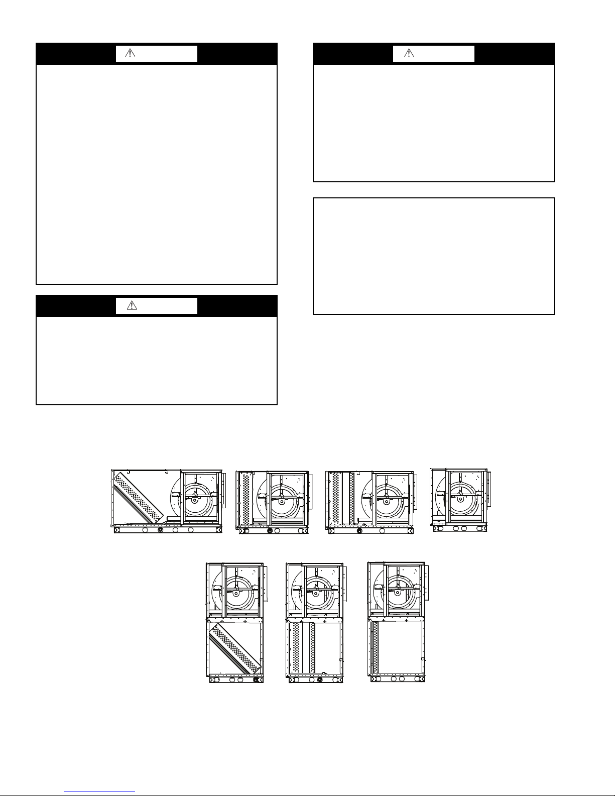
39LA
39LB
39LC
39LD
39LF
39LG
39LH
HORIZONTAL DRAW-THRU
VERTICAL DRAW-THRU
Fig. 1 — Unit Identification
a39-4440
CAUTION
DO NOT USE TORCH to remove any component. System
contains oil and refrigerant under pressure.
To remove a component, wear protective gloves and goggles and proceed as follows:
a. Shut off electrical power to unit.
b. Recover refrigerant to relieve all pressure from sys-
tem using both high-pressure and low pressure ports.
c. Traces of vapor should be displaced with nitrogen
and the work area should be well ventilated. Refrigerant in contact with an open flame produces toxic
gases.
d. Cut component connection tubing with tubing cutter
and remove component from unit. Use a pan to catch
any oil that may come out of the lines and as a gage
for how much oil to add to the system.
e. Carefully unsweat remaining tubing stubs when nec-
essary. Oil can ignite when exposed to torch flame.
Failure to follow these procedures may result in personal
injury or death.
CAUTION
DO NOT re-use compressor oil or any oil that has been
exposed to the atmosphere. Dispose of oil per local codes
and regulations. DO NOT leave refrigerant system open to
air any longer than the actual time required to service the
equipment. Seal circuits being serviced and charge with
dry nitrogen to prevent oil contamination when timely
repairs cannot be completed. Failure to follow these procedures may result in damage to equipment.
SECURE drive sheaves with a rope or strap before working on a fan to ensure that rotor cannot free-wheel.
DO NOT restore power to unit until all temporary walkways inside components have been removed.
NEVER pressurize equipment in excess of specified test
pressures.
PROTECT adjacent flammable material when welding or
flame cutting. Use sheet metal or asbestos cloth to contain
sparks. Have a fire extinguisher at hand and ready for
immediate use.
IMPORTANT: The installation of air-handling units and all
associated components, parts, and accessories which make
up the installation and subsequent maintenance shall be in
accordance with the regulations of ALL authorities having
jurisdiction and MUST conform to all applicable codes. It
is the responsibility of the installing contractor to determine
and comply with ALL applicable codes and regulations.
Field-supplied motors should be Underwriters Laboratories
(UL) or Canadian Standards Association (CSA) approved.
Field wiring must comply with National Electrical Code
(NEC) and all local requirements.
INTRODUCTION
Unit Identification —
the 18-digit part number listed on the serial plate. The part
number describes all component, coil, motor, drive, and control
selections. See Fig. 1-9 for unit identification.
The 39L units are identified by
2
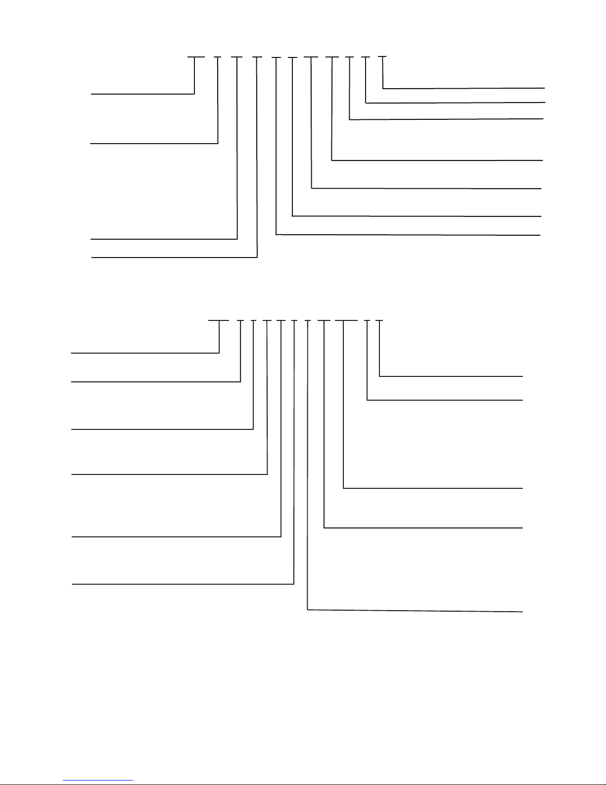
39L C 03
Fig. 2 — 39L Model Number Nomenclature
a39-4441
28N
28N – Coil Model Number
Coil Type
A – Chilled Water
Coil Orientation
S – Slant
V – Vertical
F – Full
A S 4
Rows
4
6
8
12
12
16
20
22
26
32
Tubes in Face
24
30
36
38
Q
Circuiting
Q – Quarter
H – Half
D – Double
Fin Material
Fins Per Inch
Casing Material
A – AL 8 GALV.
B
C – AL 14 GALV.
G – CU 8 ST. STL.
H
J – CU 14 ST. STL.
– AL 11 GALV.
– CU 11 ST. STL.
AB
Tube Size (Copper)
A – 0.016 Std. H-Pin
B – 0.025 Std. H-Pin
066
Nominal Length
Between Tube
Sheets (cm)
166
096
136
066
086
116
X
– Non-ferrousX
R
Hand
– Right Hand
– Left Hand
R
L
Fig. 3 — Chilled Water Coil Model Number Nomenclature
a39-4442
HB
-
A
A
CA
C
AHK
1
39L – 39L
Air Handler
Model
A
F
B
G
C
H
D
Unit Size
03
06
08
10
12
15
18
21
25
Draw-Thru Options
Special Order
Insulation/Suspension Package/Hand Side
N/A
Fan Discharge – Motor Frequency
Fan Speed
Motor HP – Type – Voltage
Base Unit Coil Description
Base Unit Coil Coil Type
and Arrangement
Preheat Coil
3
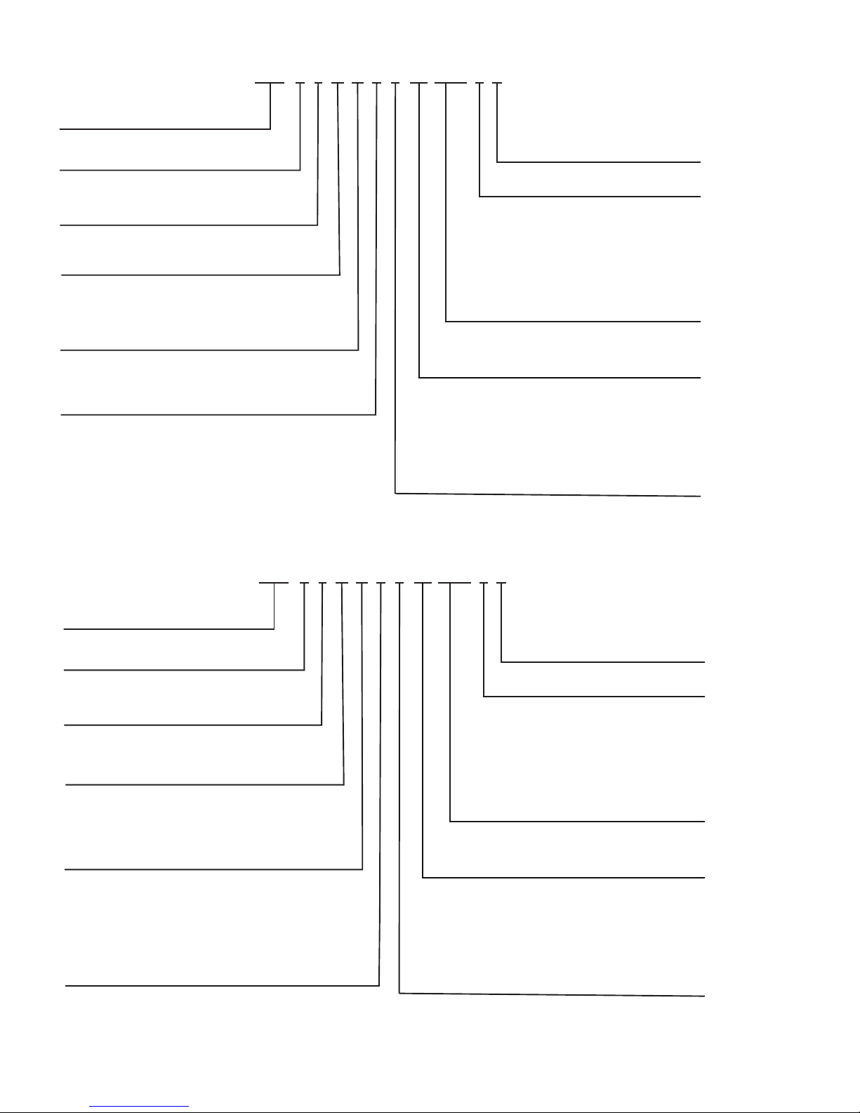
28N
28N – Coil Model Number
Coil Type
B – Hot Water
Coil Orientation
V – Vertical
F – Full
BV1
Rows
1
2
16
12
16
20
26
Tubes in Face
30
36
H
Circuiting
H
– Half
Fin Material
Fins Per Inch
Casing Material
A – AL 8 GALV.
B
C – AL 14 GALV.
G – CU 8 ST. STL.
H
J – CU 14 ST. STL.
– AL 11 GALV.
– CU 11 ST. STL.
AA
Tube Size (Copper)
A – 0.016 Std. H-Pin
B – 0.025 Std. H-Pin
086
Nominal Length
Between Tube
Sheets (cm)
166
096
136
066
086
116
X
– Non-ferrousX
L
Hand
– Right Hand
– Left Hand
R
L
Fig. 4 — Hot Water Coil Model Number Nomenclature
a39-4443
28N
28N – Coil Model Number
Coil Type
E – Direct Expansion
Coil Orientation
V – Vertical
B
– Face Split Half Circuit
EV4
Rows
4
6
16
12
16
20
26
Tubes in Face
30
36
H
Circuiting
A
– Face Split Quarter Circuit
Fin Material
Fins Per Inch
Casing Material
A – AL 8 GALV.
B
C – AL 14 GALV.
G – CU 8 ST. STL.
H
J – CU 14 ST. STL.
– AL 11 GALV.
– CU 11 ST. STL.
AA
Tube Size (Copper)
A – 0.016 Std. H-Pin
B – 0.025 Std. H-Pin
086
Nominal Length
Between Tube
Sheets (cm)
166
096
136
066
086
116
Z
– Standard (varies with coil)Z
L
Hand
– Right Hand
– Left Hand
R
L
S – Vertical
8
22
243238
C
– Face Split Full Circuit
D
– Double Circuit
E
– Row Split Quarter Circuit
F
– Row Split Half Circuit
G
– Row Split Full Circuit
Fig. 5 — Direct Expansion Coil Model Number Nomenclature
a39-4444
4
28L
28L – Coil Model Number
Coil Type
Z – Steam Distributing Tube (1 in. OD)
Coil Position
Z24
Rows
1
06
04
06
08
10
Tubes in Face
12
F
Circuiting
F
– Non-Freeze Full Circuit
D 3
Tub e Size (Copper)
3 – 1 in. OD x 0.030 Wall
086
Nominal Length
Between Tube
Sheets (cm)
166
096
136
066
086
116
--
[Blank]
2
14
Fin Material
Fins Per Inch
Casing Material
C – AL 6 GALV.
DE – AL 9 GALV.
– AL 12 GALV.
--
[Blank]
Fig. 6 — Steam Distributing Tube Model Number Nomenclature
a39-4445
39L
28L – Drive Package Model Number
Drive Type
V – Variable Speed
Fan Type
K212
Unit Size
Large Face Area (sq. ft.)
10 B A 1250
Position 12 is 0 if rpm is 3 digits
1
Motor Horsepower
– Constant SpeedK
– Forward Curve without VFD
2 – Forward Curve with VFD
03
06
08
10
12
15
18
21
25
01
02
03
04
05
06
07
08
09
10
11
12
13
– ½ hp
– ¾ hp
– 1 hp
– 1 ½ hp
– 2 hp
– 3 hp
– 5 hp
– 7 ½ hp
– 10 hp
– 15 hp
– 20 hp
– 25 hp
– 30 hp
Motor rpm
60 Hz
– 1200A
BC – 1800
– 3600
50 Hz
– 1000D
EF – 1500
– 3000
Motor Type
XL (Across-the-Line)
– Open Drip ProofA
BC – Totally Enclosed, Non-Ventilated
– Totally Enclosed, Fan-Cooled
D
– Explosion Proof
E
– Encapsulated (Open Drip Proof Frame)
PW (Part-Wind)
– Open Drip Proof
– Totally Enclosed, Non-Ventilated
– Totally Enclosed, Fan-Cooled
– Explosion Proof
– Encapsulated (Open Drip Proof Frame)
F
G
H
J
K
Fan Speed rpm
3
3
Safety Factor
– 1 Set Belt
1.5 Safety Factor
Fig. 7 — Drive Package Model Number Nomenclature
a46-4446
5
PRE-HEAT
WATER
OR
PRE-HEAT
STEAM
PHW
LEGEND
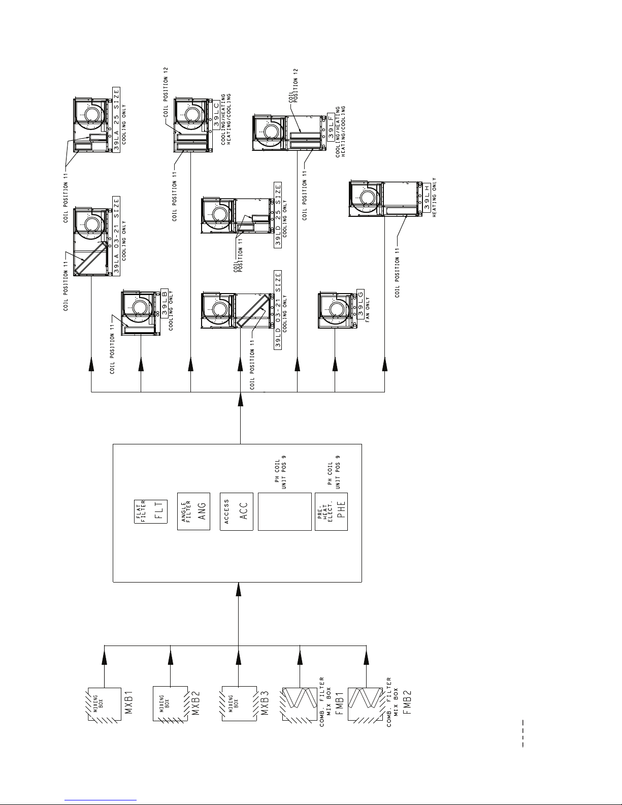
Fig. 8 — Position 4, Unit Configuration Model
(Component Sequence Also Shown)
COMB. — Combination
PH — Preheat
POS. — Position
Factory-installed option components
6
39LA – HORIZONTAL COOLING
LARGE FACE AREA
1
AB
PRIMARY COIL/FAN SECTIONS
C
39LB – HORIZONTAL COOLING
SMALL FACE AREA
2
AB
C
39LC – HORIZONTAL COOLING/HEATING
SMALL FACE AREA
3
AB
C
39LD – VERTICAL COOLING
LARGE FACE AREA
4
AB
C
39LF – VERTICAL COOLING/HEATING
SMALL FACE AREA
5
AB
C
39LG – FAN ONLY
6
AB
C
39LH – VERTICAL HEATING
SMALL FACE AREA
AB
C
7
ACCESSORY SECTIONS
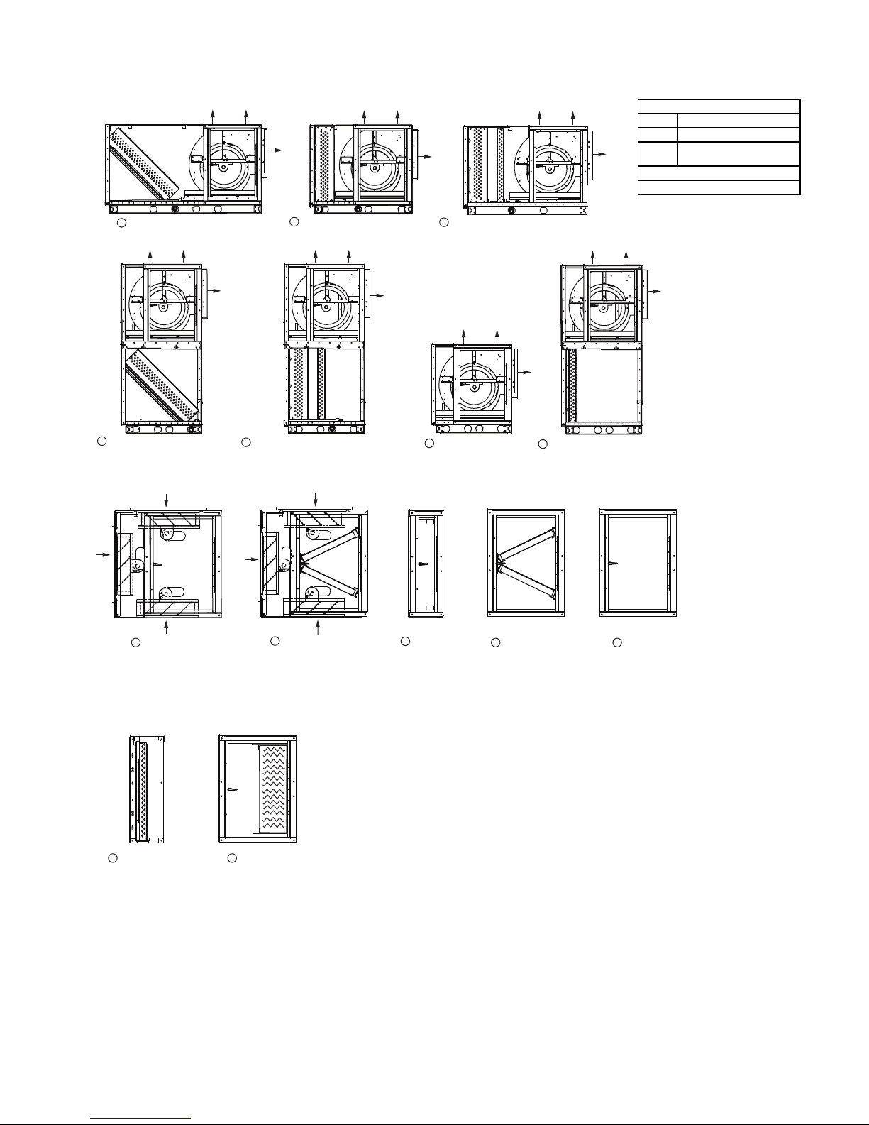
Fig. 9 — Section Details
Fan Configurations
Available Configurations
A Upblast Rear Discharge
B Upblast Front Discharge
C
Top Horizontal Front
Discharge
Fan Section Access
Hinged Door on Hand Side
NOTE: Item numbers refer to Table 1.
a39-4447
a39-4448
MIXING BOX8
PREHEAT SECTIONS
13
HOT WATER
OR STEAM
PREHEAT COIL
9
FILTER MIXING BOX
FILTER MIXING BOX
14
ELECTRIC
PREHEAT
COIL
10
FLAT FILTER
11
ANGLE FILTER
12
PLENUM
7

Table 1 — Section Dimensions and Weights
LEGEND
AWL — Airway Length
NOTE: Unit weights do not include coils and motors.
SECTION DIMENSIONS (in.) AND WEIGHTS (lb)
Nominal cfm at 500 fpm 1,500 3,000 4,000 5,000 6,000 7,500 9,000 10,500 12,500
Unit Size 03 06 08 10 12 15 18 21 25
Height (in.) LA, LB, LC, LG 24.3 28.2 32.1 32.1 32.1 40.0 43.9 43.9 43.9
Height (in.) LD, LF, LH 45.5 53.3 61.3 61.3 61.3 76.9 84.8 84.8 100.6
Width (in.) 37.9 45.8 49.7 57.6 65.1 65.1 65.1 77.3 77.3
ITEM
NO.*
1 39LA
2 39LB
3 39LC
4 39LD
5 39LF
639LG
7 39LH
ACCESSORIES
ITEM
NO.*
8 Mixing Box Section
9 Filter Mixing Box
10 Flat Filter Section
11 Angle Filter Section
12 Access Section
13
14 Preheat (Electric) Section
DESCRIPTION
Unit Size 03 06 08 10 12 15 18 21 25
Height (in.) 24.3 28.2 32.1 32.1 32.1 40.0 43.9 43.9 43.9
Width (in.) 37.9 45.8 49.7 57.6 65.1 65.1 65.1 77.3 77.3
DESCRIPTION
Preheat (Hot Water or
Steam) Section
40.9 48.8 56.7 56.7 56.7 72.4 80.3 80.3 76.4
200 280 411 470 540 620 695 740 820
29.1 33.1 37.0 37.0 37.0 44.9 48.8 48.8 56.7
150 210 308 352 405 465 521 555 615
37.0 40.9 44.9 44.9 44.9 52.8 56.7 56.7 64.6
170 238 349 400 459 527 590 629 697
21.3 25.2 29.1 29.1 29.1 37.0 40.9 40.9 48.8
230 322 472 540 621 713 799 851 943
21.3 25.2 29.1 29.1 29.1 37.0 40.9 40.9 48.8
230 322 472 540 621 713 799 851 943
21.3 25.2 29.1 29.1 29.1 37.0 40.9 40.9 48.8
120 168 246 282 324 372 417 444 492
21.3 25.2 29.1 29.1 29.1 37.0 40.9 40.9 48.8
220 308 452 517 594 682 764 814 902
27.6 27.6 27.6 27.6 27.6 27.6 35.4 35.4 35.4
139 164 193 219 226 244 283 272 311
27.6 27.6 27.6 27.6 27.6 27.6 35.4 35.4 35.4
150 173 208 227 245 279 327 340 395
7.9 7.9 7.9 7.9 7.9 7.9 7.9 7.9 7.9
37 43 48 50 55 74 75 86 90
19.7 19.7 19.7 19.7 19.7 19.7 19.7 19.7 19.7
75 82 97 107 114 134 140 159 185
19.7 19.7 19.7 19.7 19.7 19.7 19.7 19.7 19.7
48 55 60 64 68 74 77 87 92
7.9 7.9 7.9 7.9 7.9 7.9 7.9 7.9 7.9
36 42 43 46 49 52 54 53 57
19.7 19.7 19.7 19.7 19.7 19.7 19.7 19.7 19.7
49 56 61 66 72 74 76 87 89
AWL (in.)
Weight (lb)
AWL (in.)
Weight (lb)
* Item numbers refer to Fig. 9.
8
PREINSTALLATION
1. Check items received against packing list. Notify Carrier
of any discrepancy.
2. Refer to Fig. 10 for service area requirements.
3. To transfer unit from truck to storage site, refer to rigging
details in Fig. 11 and section on unit rigging for proper
handling. See Tables 1 and 2 for section and component
weights.
CAUTION
If a fork lift truck is used, lift only from heavy end of skid.
Minimum recommended fork length is 48 inches.
4. Do not stack unit components or accessories during storage. Stacking can cause damage or deformation.
5. If unit is to be stored for more than 2 weeks prior to installation, observe the following precautions:
a. Choose a dry storage site that is reasonably level
and sturdy to prevent undue stress or permanent
damage to the unit structure or components. Do not
store unit on vibrating surface. Damage to stationary bearings can occur. Set unit off ground if in
heavy rain area.
b. Remove all fasteners and other small parts from
jobsite to minimize theft. Tag and store parts in a
safe place until needed.
c. Cover entire unit with a tarp or plastic coverall.
Extend cover under unit if stored on ground.
Secure cover with adequate tiedowns or store
indoors. Be sure all coil connections have protective shipping caps.
d. Monthly — Remove tarp from unit, enter fan
section through access door or through fan inlet,
and rotate fan and motor slowly by hand to redistribute the bearing grease and to prevent bearing
corrosion.
Rigging (Fig. 11) — All 39L units can be rigged by
means of the lifting brackets on bottom of unit.
Units are shipped fully assembled. Do not remove shipping
skids or protective covering until unit is ready for final placement. Use slings and spreader bars as applicable to lift unit. Do
not lift unit by coil connections or headers.
Do not remove protective caps from coil piping connections
until ready to connect piping.
Do not remove protective cover or grease from fan shaft until ready to install sheave.
Lay rigid temporary protection such as plywood walkways
in unit to prevent damage to insulation or bottom panel during
installation.
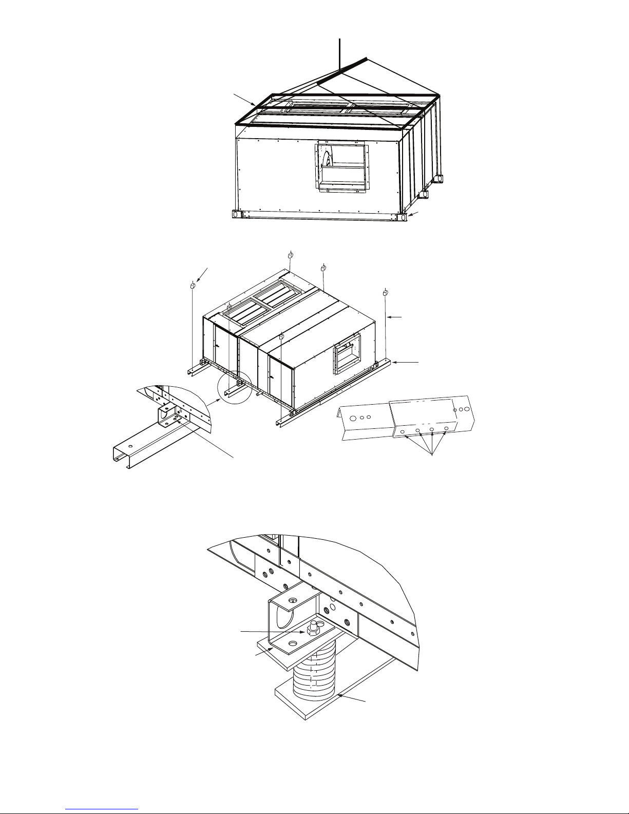
Suspended Units — Figure 12 shows overhead suspen-
sion of unit using optional factory-supplied suspension
channels.
Each support channel consists of 2 pieces, the smaller of
which fits inside the larger one. This allows the channel to be
adjusted to the required length for installation.
Channels are shipped on top of the unit. The 2 sections of
each channel are shipped one inside the other, and are held in
place during shipping by the panel screws in the top panel.
Hardware required for installation of suspension channels is
shipped in a package inside the fan section.
At least 2 suspension channels are shipped with each fan
and coil unit. One or more extra channels will be supplied
depending on the number of accessories ordered. Be sure to
install all the suspension channels shipped with a unit. Refer to
39L Isolator Mounting (Suspended Unit) certified drawing for
details.
To install suspension channels:
1. Remove panel screws to free suspension channels for installation. Replace screws in top panel.
2. Adjust channel to required length by sliding one channel
section inside the other. The channel must extend at least
9 in. but not more than 12 in. beyond the edge of the unit.
Set length of channel by installing factory-supplied bolts
through the overlapping channel sections.
3. Mount unit to suspension channel using factory-supplied
nuts and bolts through
7
/16-in. diameter holes in unit lift-
ing bracket.
4. Install field-supplied suspension rods through
9
/16-in. diameter holes provided at outer edges of channel. Be sure
hanger rods are securely fastened in place.
Service Clearance — Provide adequate space for unit
service access (fan shaft and coil removal, filter removal, motor access, damper linkage access, etc.) as shown in Fig. 10.
Condensate Drain — To prevent excessive build-up of
condensate in drain pan, adequate trap clearance must be provided beneath the unit. See Installation, Condensate Drain section on page 16 for additional details.
External Vibration Isolators — Install vibration iso-
lators per certified drawings, and in accordance with the job
specifications and the instructions of the vibration isolator
manufacturer. The coil piping must be isolated or have a flexible connection to avoid coil header damage because of unit
motion. A flexible connection should be installed at the fan discharge.
Fig. 12 and 13 show isolation location for overhead suspen-
sion or floor mounting of unit.
9
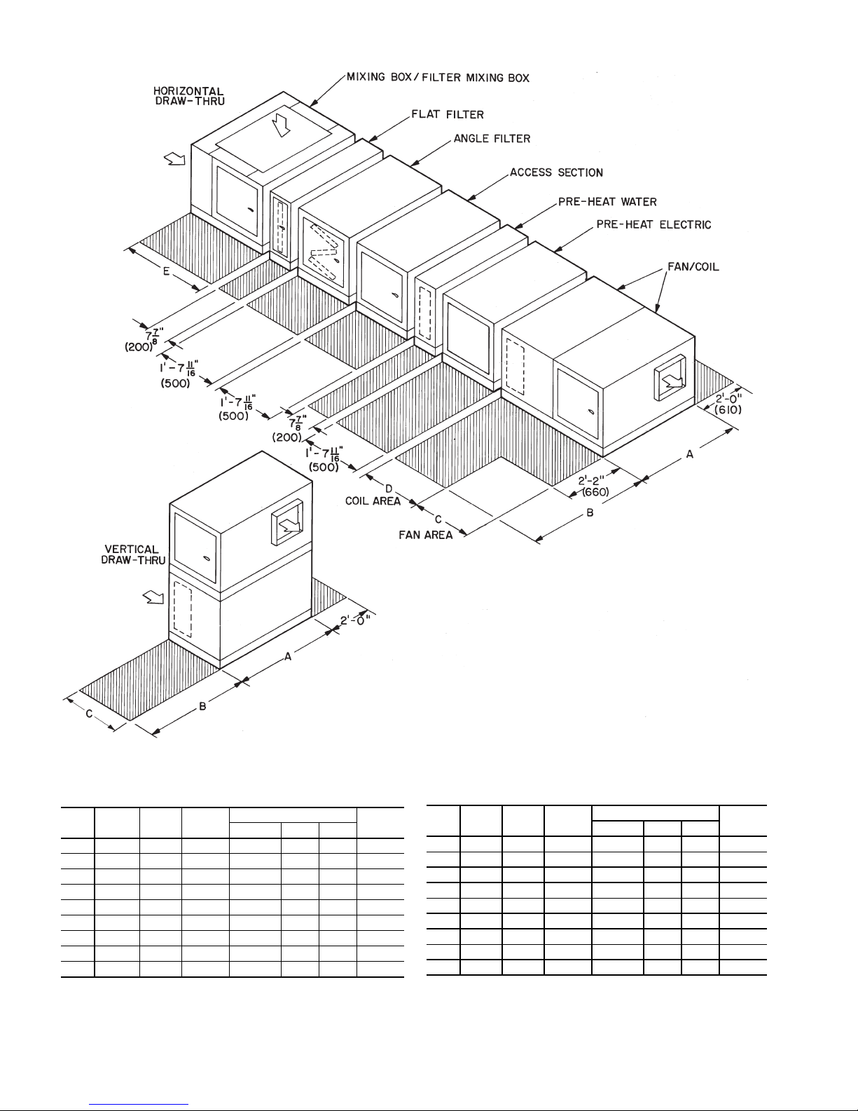
NOTE: Dimensions are in inches, ( ) are in mm.
DIMENSIONS (ft-in.)
SIZE A B C
D
E
39LA 39LB 39LC
03 3-17/83-13/41-91/41- 711/160-77/81-33/42- 39/
16
06 3-93/43-95/82-13/161-115/80-77/81-33/42- 39/
16
08 4-111/164-19/162-51/82- 39/160-77/81-33/42- 39/
16
10 4-99/164-97/162-51/82- 39/160-77/81-33/42- 39/
16
12 5-51/165-55/162-51/82- 39/160-77/81-33/42- 39/
16
15 5-51/165-55/163-1 2-119/160-77/81-33/42- 39/
16
18 5-51/165-55/163-415/163- 33/80-77/81-33/42-117/
16
21 6-51/46-51/83-415/163- 33/80-77/81-33/42-117/
16
25 6-51/46-51/84-015/162- 39/160-77/81-33/42-117/
16
DIMENSIONS (mm)
SIZE A B C
D
E
39LA 39LB 39LC
03 952 959 540 500 200 400 700
06 1162 1159 640 600 200 400 700
08 1262 1259 740 700 200 400 700
10 1462 1459 740 700 200 400 700
12 1653 1659 740 700 200 400 700
15 1653 1659 940 900 200 400 700
18 1653 1659 1040 1000 200 400 900
21 1962 1959 1040 1000 200 400 900
25 1962 1959 1240 700 200 400 900
Fig. 10 — Service Area Requirements
10

Table 2 — Additional Component Weights
UNIT SIZE 03 06 08 10 12 15 18 21 25
TYPICAL DRY COIL WEIGHTS (lb)
Large Face Area Cooling Coils,
1
/
-in. OD (Chilled Water & DX)*
2
4-Row 56 84 98 109 137 178 198 251 280
6-Row 63 95 123 138 174 234 270 327 363
Small Face Area Cooling Coils,
1
/
-in. OD (Chilled Water & DX)*
2
4-Row 45 72 91 105 133 161 182 211 238
6-Row 53 85 113 129 162 197 225 270 307
8-Row 61 92 129 143 189 228 263 324 377
Hot Water Coils,
1-Row 19 34 38 48 58 62 77 86 95
2-Row 28 43 51 61 76 89 104 117 130
Steam Coils, 1-row, 1-in. OD
6-FPI 50 70 85 95 110 135 150 180 215
9-FPI 55 80 100 115 125 155 175 214 256
12-FPI 60 85 115 130 145 180 205 248 297
FAN
Wheel Diameter (in.) 9
Wheel Width (in.) 7
Shaft Diameter (in.) 3/4 1
Maximum Fan Rpm 2500 2000 2000 1600 1600 1400 1300 1100 1000
OPERATING CHARGE (Approximate),
DIRECT EXPANSION COIL
Refrigerant R-410A or R-22 (lb)
4-Row Coil 1-2 2-3 3-4 4-5 4-5 5-6 6-7 6-8 6-9
6-Row Coil 1-2 2-4 5-6 5-6 6-8 8-10 9-11 11-13 11-16
8-Row Coil 2-3 3-5 5-6 5-7 7-9 10-12 12-14 13-19 16-24
COIL VOLUME (gal. water)
Chilled Water,
Large Face Area
4-Row 2.5 3.5 4.5 5.2 5.6 7.3 8.5 10.4 12.0
6-Row 3.2 4.7 6.0 6.8 7.7 10.1 11.7 14.2 16.3
Chilled Water,
Small Face Area
4-Row 2.1 3.3 3.9 4.1 5.1 6.3 7.3 8.7 9.8
6-Row 2.4 3.7 5.1 5.9 6.6 8.3 9.5 11.8 13.5
8-Row 2.7 4.1 6.4 7.4 8.4 10.7 12.1 14.7 17.2
Hot Water,
1-Row 0.5 0.8 1.0 1.3 1.5 1.8 2.1 2.5 2.9
2-Row 0.7 1.3 1.6 2.0 2.4 2.9 3.4 4.0 4.8
COOLING COILS
Chilled Water
(4, 6 Row) Large Face Area
Face Area (sq ft) 3.63 5.90 7.90 9.54 11.18 14.91 17.71 21.6 25.0
Number of Tubes/Face 16 20 24 24 24 32 38 38 44
Finned Tube Length (in.) 26.1 34.0 37.9 45.8 53.7 53.7 53.7 65.5 65.5
Chilled Water
(4, 6, 8 Row) Small Face Area
Face Area (sq ft) 2.72 4.72 6.58 7.95 9.32 12.12 13.98 17.1 20.5
Number of Tubes/Face 12 16 20 20 20 26 30 30 36
Finned Tube Length (in.) 26.1 34.0 37.9 45.8 53.7 53.7 53.7 65.5 65.5
1
DX
/
-in. OD Tube
2
(4, 6 Row) Large Face Area
Face Area (sq ft) 3.63 5.90 7.90 9.54 11.18 14.91 17.71 21.6 25.0
Finned Tube Length (in.) 26.1 34.0 37.9 45.8 53.7 53.7 53.7 65.5 65.5
1
DX
/
-in. OD Tube
2
(4, 6, 8 Row) Small Face Area
Face Area (sq ft) 2.72 4.72 6.58 7.95 9.32 12.12 13.98 17.1 20.5
Finned Tube Length (in.) 26.1 34.0 37.9 45.8 53.7 53.7 53.7 65.5 65.5
HEATING COILS
Hot Water
U-Bend (1, 2 Row)
Face Area (sq ft) 2.72 4.72 6.58 7.95 9.32 12.12 13.98 17.1 20.5
Number Tubes/Face 12 16 20 20 20 26 30 30 36
Finned Tube Length (in.) 26.1 34.0 37.9 45.8 53.7 53.7 53.7 65.5 65.5
Steam 1-in. OD (1 Row)
Face Area (sq ft) 2.13 4.18 6.22 7.53 8.85 11.06 13.28 16.2 18.9
Number Tubes/Face 4688 8 10121214
Finned Tube Length (in.) 25.5 33.4 37.3 45.2 53.1 53.1 53.1 53.1 64.9
LEGEND
DX — Direct Expansion
FPI — Fins Per Inch
1
/
2
1
/
-in. OD Tube,
2
1
/
-in. OD Tube,
2
1
/
-in. OD Tube
2
1
/
-in. OD Tube,
2
1
/
-in. OD Tube
2
1
/
-in. OD Tube,
2
-in. OD*
1
/
2
1
/
8
5
12
/
1
9
/
2
3
/
16
5
12
/
8
1
11
3
1
/
15 15 18
8
/
16
1
11
8
/
8
3
1
/
16
15 15 13
3
1
/
16
1
/
7
1
/
16
20 20 25
8
1
/
2
7
1
/
16
18 15
7
1
/
16
11
1
/
16
*Coils have 14 aluminum fins per inch on copper tubes.
NOTE: See Table 1 for section weights and dimensions.
11
SPREADER
BAR
LIFTING
BRACKET
Fig. 11 — Unit Rigging Details
NOTE: Lift in one piece. Use slings and
spreader bars at each lifting bracket.
a39-4449
LIFTING BRACKET
DETAILS
7
16
/
IN. DIAM. HOLE
VIBRATION ISOLATORS
(FIELD SUPPLIED)
SUSPENSION ROD
(FIELD SUPPLIED)
SUSPENSION CHANNEL
(FACTORY-SUPPLIED OPTION)
MOUNT UNIT TO SUSPENSION CHANNELS
THROUGH
PROVIDED IN LIFTING BRACKET
7
16
/
IN. DIAM. HOLES
FACTORY-SUPPLIED BOLTS
CONNECTING SUSPENSION
CHANNEL SECTIONS
OVERHEAD SUSPENSION
Fig. 12 — Unit Support Details, Overhead Suspension
a39-4450
SPRING ISOLATOR
ISOLATION BRACKET
7
16
/
IN. DIAM. HOLE
ISOLATION DETAIL – FLOOR MOUNT
Fig. 13 — Unit Support Details, Floor Mount
a38-4451
12
INSTALLATION
T-BRACKET
LIFTING LUG
Fig. 14 — Base Rail Split — T-Bracket
a39-4453
FLANGES
FLANGES
Fig. 15 — Base Rail Split — Flanges
a39-4454
Fig. 16 — Base Rail Split — Screws
a39-4455
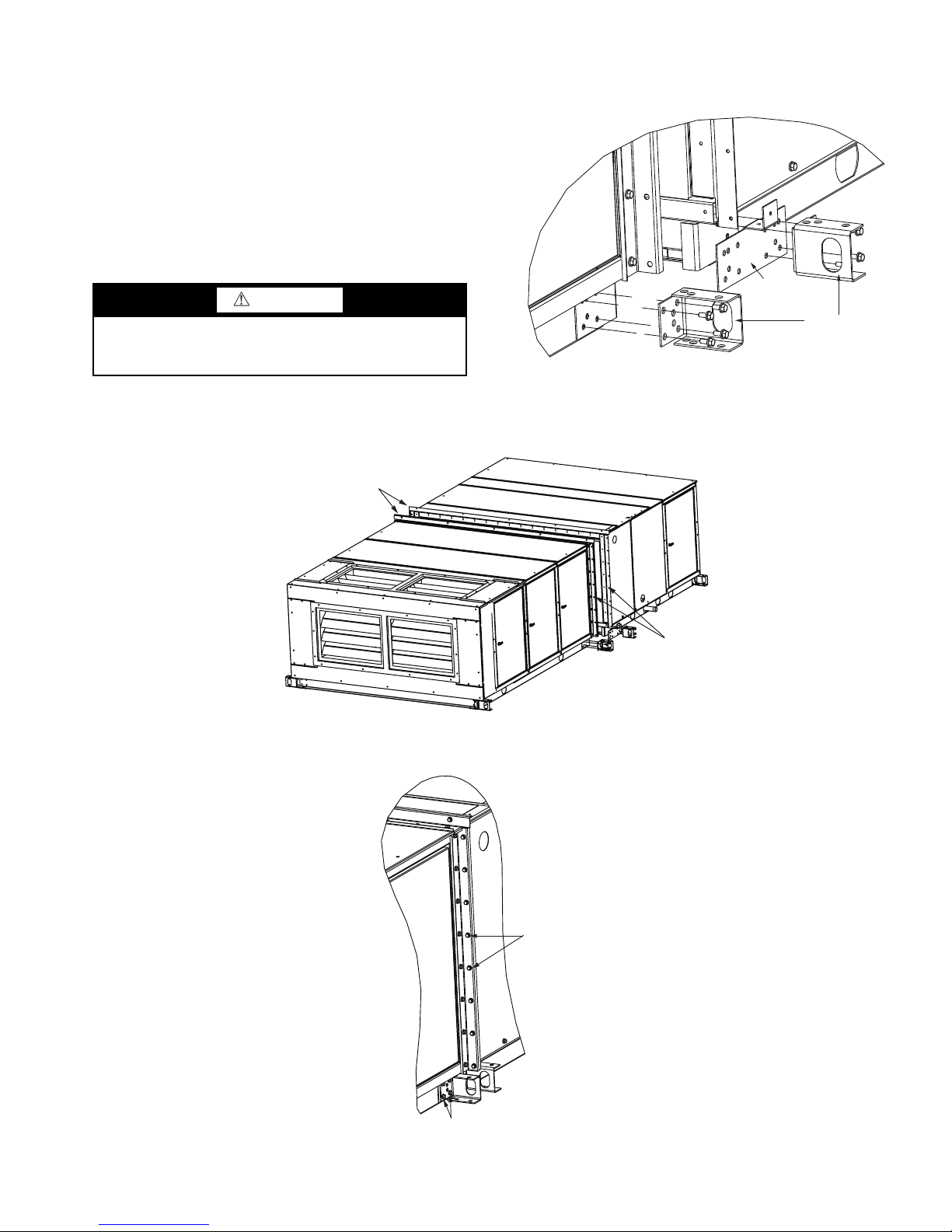
Base Rail Split —
coil/fan section and the accessory sections is optional. If this
option has ben selected, the 39L unit will arrive at the job site
assembled as one piece. The split allows the unit to be separated at the joint.
If the unit must be separated in the field, follow this procedure:
1. Remove the lifting lugs on the inlet side of the coil/fan
section and those on the outlet side of the accessory section to liberate the T-bracket. See Fig 14.
2. Unscrew the flanges (top and sides) around the coil/fan
section and the accessory section. See Fig. 15.
A base rail split between the primary
CAUTION
Ensure that a good seal is created between both sections
before continuing. A poor seal may result in equipment
damage.
NOTE: If the section-to-section gasket installed at the factory
is damaged while splitting the unit, obtain the required length
1
of
/8 in. x 1 1/4 in. foam gasketing locally.
1
After rejoining the split sections, fully tighten all AB
/4 in.-3/
in. screws on the flanges and the AB 1/4 in-5/8 in. screws on the
flanges. See Fig. 16.
4
AB ¼-
5
SCREWS
8
/
13
AB ¼-¾ SCREWS
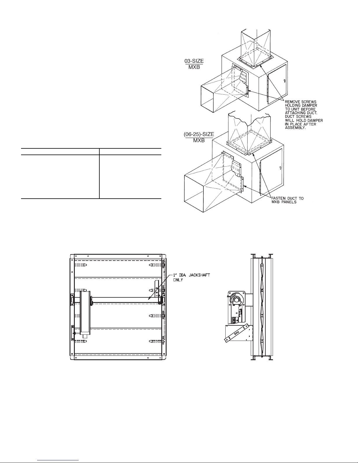
Mixing Box
MXB — Mixing Box
Fig. 18 — Mixing Box Ductwork Attachment
Fig. 17 — Typical Mixing Box Actuator Mounting
DAMPER ACTUATORS — The 39L mixing boxes are supplied with low leak dampers and blade and edge seals. Damper
operating torques are shown in Table 3.
The actuator and mounting brackets are field supplied and
may be mounted inside or outside the unit. A typical inside
mounting bracket is shown in Fig. 17. For external mounting of
actuators, drill or punch a hole in the exterior panel.
NOTE: If the unit is shipped with AirManager™ controls,
actuator(s) are factory-supplied. Refer to Table 4.
To ensure torque is transmitted equally to both damper sections, actuator must be connected to the 1-in. hollow jackshaft
that drives the interconnecting linkage bar. Connection to any
other shaft is not recommended.
DUCTWORK ATTACHMENT — Ductwork should be
flanged out and attached to the mixing box panels as shown in
Fig. 18. See Fig. 19 for duct connection sizes.
Table 3 — Mixing Box Damper Operating Torque
(in.-lb)
39L UNIT SIZE TORQUE
03 20
06 20
08 26
10 29
12 33
15 41
18 52
21 56
25 76
NOTES:
1. Torque values are based on interconnected dampers driven by
one operator. For units with separate operators for each
damper, calculate torque as follows: Table values x .80 = torque
per damper section.
2. Damper shaft moves 90 degrees from open to closed position.
14
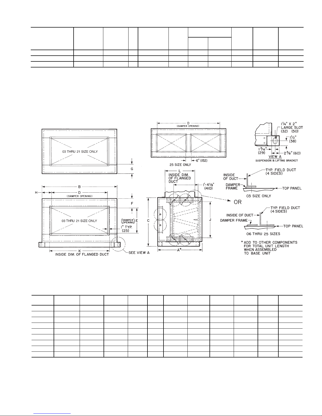
Table 4 — Recommended Actuators
DIMENSIONS (ft-in.)
Fig. 19 — Mixing Box Duct Connections
UNIT
39L-
A B C D E F G H J K L
03 2- 39/
16
3-17/
8
2-01/
4
1- 5 1-5 0- 15/
8
0-61/
16
0-101/
2
1-43/
4
1-51/
4
1- 51/
4
06 2- 39/
16
3-93/
4
2-43/
16
1-11 1-5 0- 41/
8
0-61/
16
0-113/
8
1-811/
16
2-11/
4
1- 71/
4
08 2- 39/
16
4-111/
16
2-81/
8
3- 1 1-5 0- 61/
16
0-61/
16
0- 63/
8
2-05/
8
3-31/
4
1- 71/
4
10 2- 39/
16
4-99/
16
2-81/
8
3- 5 1-5 0- 61/
16
0-61/
16
0- 85/
16
2-05/
8
3-71/
4
1- 71/
4
12 2- 39/
16
5-57/
16
2-81/
8
3-11 1-5 0- 61/
16
0-61/
16
0- 91/
4
2-05/
8
4-11/
4
1- 71/
4
15 2- 39/
16
5-57/
16
3-4 3-11 1-9 0- 8 0-41/
16
0- 91/
4
2-81/
2
4-11/
4
1-111/
4
18 2-117/
16
5-57/
16
3-715/
16
3-11 2-3 0- 7 0-5 0- 91/
4
3-07/
16
4-11/
4
2- 51/
4
21 2-117/
16
6-51/
4
3-715/
16
3-11 2-5 0- 6 0-4 1- 31/
8
3-07/
16
4-11/
4
2- 71/
4
25 2-117/
16
6-51/
4
4-313/
16
5- 4 2-5 0- 97/
8
0-4 0- 65/
8
3-85/
16
5-61/
4
2- 71/
4
NOTES:
1. Hand is determined by the location of the fan drive and/or coil connection when viewed
while facing the direction toward which air is flowing.
2. Dimensions are in inches, ( ) are in millimeters.
ACCESSORY
PACKAGE
NO.
ACTUATOR
PART NO.
VOLTAGE
(50/60 Hz)
VA
ROUND
SHAFT
SIZE
MIN-MAX
(in.)
TIMING
(sec)
DAMPER AREA
(sq ft)
Parallel Opposed
TORQUE
(in.-lb)
MAXIMUM
STROKE
(degrees)
MAXIMUM
WIRE
LENGTH
33AMACTDMP133 HF27BJ035* 24 10 0.750-1.050 150 44 53 133 90 300
33AMACTGV-133 HF27BJ033 24 4 0.375-0.625 < 150 N/A N/A 133 90 725
33AMACTGV-266 HF27BJ034 24 6 0.475-0.750 135 N/A N/A 266 90 450
*Actuator is spring-return type.
NOTES:
1. All actuators are direct coupled type, designed to be directly
mounted into jackshaft assembly.
2. All actuators are equipped with a plenum rated cable, factoryterminated to the actuator. Part No. HF27BB035 and 034 are
16 ft, HF27BB033 is 9.5 ft.
3. Damper areas are nominal and based on low leakage type
dampers.
4. For larger damper assemblies, multiple activators may be used.
5. Part No. HF27BB033 and 034 are designed for inlet guide vane
and face and bypass applications, but may be used for external
relief dampers if spring return is not required.
(ft)
15
 Loading...