


38APD030
Carrier 38APD030, 38APD040, 38APD050, 38APD060, 38APD070 Installation Instructions Manual
...
38APS025-050,38APD025-100 Air-Cooled Condensing Units
Installation Instructions
CONTENTS
Page
SAFETY CONSIDERATIONS . . . . . . . . . . . . . . . . . . . . . . 1
INSTALLATION . . . . . . . . . . . . . . . . . . . . . . . . . . . . . . . . 1-34
Step 1 — Inspect Shipment . . . . . . . . . . . . . . . . . . . . . . 1
Step 2 — Rig and Place Unit . . . . . . . . . . . . . . . . . . . . . 1
• DOMESTIC UNITS
• EXPORT UNITS
•PLACING UNITS
Step 3 — Make Refrigerant Piping
Connections . . . . . . . . . . . . . . . . . . . . . . . . . . . . . . . . . . 17
• SIZE REFRIGERANT LINES
• LIQUID LINE SOLENOID VALVE
• THERMOSTATIC EXPANSION VALVES
• LIQUID LINE FILTER DRIER
• LONG LINE APPLICATIONS
• HOT GAS BYPASS
• FINAL CONNECTION AND LEAK TEST
• EVACUATION AND DEHYDRATION
Step 4 — Make Electrical Connections . . . . . . . . . . 26
• POWER SUPPLY
•POWER WIRING
• CONTROL POWER
• FIELD CONTROL WIRING
Step 5 — Install Accessories . . . . . . . . . . . . . . . . . . . . 34
• LOW-AMBIENT OPERATION
• MISCELLANEOUS ACCESSORIES
SAFETY CONSIDERATIONS
Installing, starting up, and servicing this equipment can be
hazardous due to system pressures, electrical components, and
equipment location (roofs, elevated structures, etc.).
Only trained, qualified installers and service mechanics
should install, start up, and service this equipment.
Untrained personnel can perform basic maintenance functions, such as cleaning coils. All other operations should be
performed by trained service personnel.
When working on the equipment, observe precautions in the
literature, and on tags, stickers, and labels attached to the
equipment and any other safety precautions that may apply.
• Follow all safety codes.
• Wear safety glasses and work gloves.
• Use care in handling, rigging, and setting bulky
equipment.
WARNING
Open all remote disconnects before servicing this equipment. Failure to do so could result in personal injury from
electric shock.
GEMINI™ SELECT
with PURON® Refrigerant (R-410A)
50/60 Hz
CAUTION
Puron refrigerant (R-410A) systems operate at higher pressures than standard R-22 systems. Do not use R-22 service
equipment or components on Puron refrigerant equipment.
If service equipment is not rated for Puron refrigerant,
equipment damage or personal injury may result.
INSTALLATION
Step 1 — Inspect Shipment —
age upon arrival. If damage is found, immediately file a claim
with the shipping company. Verify proper unit delivery by
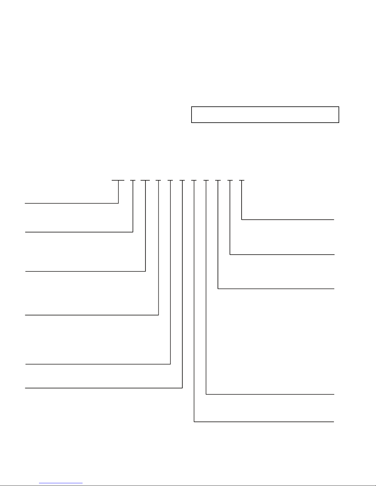
checking unit nameplate data and the model number nomenclature shown in Fig. 1. See Tables 1-4 for unit physical data.
Step 2 — Rig and Place Unit — All units are de-
signed for overhead rigging, and it is important that this method be used. Lifting holes are provided in the frame base rails. It
is recommended to use shackles in the lifting holes (see rigging
label on the unit and Table 5, and Fig. 2 and 3 for rigging
weights and center of gravity). All panels must be in place
when rigging.
IMPORTANT: To maintain unit stability while lifting,
use 4 cables, chains or straps of equal length. Attach one
end of each cable to shackle attachment point and the
other end of each cable to the overhead rigging point.
Use spreader bars or frame to keep the cables, chains, and
straps clear of the unit sides. Leave standard coil protection
packaging in place during rigging to provide protection to
coils. Remove and discard all coil protection after rigging cables are detached.
CAUTION
All panels must be in place when rigging. Failure to comply could result in equipment damage.
CAUTION
For unit sizes 025 to 060 when handling with a forklift,
handle only through fork pocket holes. Failure to follow
this caution could result in equipment damage or personal
injury.
CAUTION
For unit sizes 070 to 100, do not forklift the unit unless unit
is attached to a skid designed for forklifting. Failure to follow this caution could result in equipment damage or personal injury.
Inspect unit for dam-
Manufacturer reserves the right to discontinue, or change at any time, specifications or designs without notice and without incurring obligations.
Catalog No. 04-53380002-01 Printed in U.S.A. Form 38AP-1SI Pg 1 8-09 Replaces: New
DOMESTIC UNITS — Standard 38AP unit packaging con-
38AP D 025 6 4 A 1 0 0 5 0
38AP – Split System Condensing Unit Packaging/Security Options
0 – Std Packaging
8 – Std Packaging, Bottom Skid
J – Bottom Skid, Top Crate, Bag
Controls/Communications Options
2 – Scrolling Marquee
3 – EMM, Scrolling Marquee
5 – No Display
Ambient/Capacity Control/
Interrupt Options
0 – Std Ambient, Std Compressor,
Std Interrupt
2 – Std Ambient, Digital Compressor,
Std Interru
pt
3 – Std Ambient, Std Compressor,
High Interrupt
5 – Std Ambient, Digital Compressor,
High Interrupt
6 – Low Ambient, Std Compressor,
Std Interrupt
8 – Low Ambient, Digital Compressor,
Std Interrupt
9 – Low Ambient, Std Compressor,
High Interrupt
C – Low Ambient, Digital Compressor,
High Interrupt
Line Length Options
1 – Standard Line Length
2 – Long Line Length Check Valves
Electrical Options
0 – Single Point Power, Terminal Block
1 – Single Point Power,
Non-Fused Disconnect
Refrigeration Circuit Options
*
D – Dual Refrigeration Circuit
S – Single Refrigeration Circuit
Revision Level
A – Current Revision Level
ylppuS rewoP
1 – 575-3-60
2 – 380-3-60
5 – 280/230-3-60
6 – 460-3-60
9 – 380/415-3-50
Condenser Coil/Low Sound Options
4 – MCHX, No Sound Treatment
5 – E-coat, MCHX, No Sound Treatment
C – MCHX, Low Sound Fan(s)
D
– E-coat MCHX, Low Sound Fan(s)
H – MCHX, Low Sound Fan(s), Compressor Blankets
J – E-coat MCHX, Low Sound Fan(s), Compressor Blankets
Nominal Capacity – Tons (kW)
025 – 25 (88) 050 – 50 (176) 090 – 90 (317)
027 – 27 (95) 060 – 60 (211) 100 – 100 (352)
030 – 30 (106) 070 – 70 (246)
040 – 40 (141) 080 – 80 (281)
LEGEND
*38APS units available in sizes 025-050 only.
EMM — Energy Management Module
MCHX — Microchannel Heat Exchanger
a38-7100.eps
Fig. 1 — Model Number Nomenclature
sists of coil protection only. Skids are not provided. If overhead
rigging is not available at the jobsite, place the unit on a skid or
pad before dragging or rolling. When rolling, use a minimum
of 3 rollers. When dragging, pull the pad or skid. Do not apply
force to the unit. When in final position, raise from above to lift
unit off the pad or skid.
EXPORT UNITS — All export units are mounted on skids
with vertical coil protection. Leave the unit on the skid until it
is in final position. While on the skid, the unit can be rolled or
skidded. Apply force to the skid, not to the unit. Use a minimum of 3 rollers when rolling. When in final position, raise
from above to remove the skid.
PLACING UNITS — When considering location of the unit,
be sure to consult National Electrical Code (NEC, U.S.A.) and
local code requirements. Allow sufficient space for airflow,
wiring, piping, and service. The placement area must be level
and strong enough to support the operating weight of the unit.
(See Table 5.) When unit is in proper location, use of mounting
holes in base rails is recommended for securing unit to
supporting structure. For mounting unit on vibration isolators,
4 x 24 in. perimeter support ASTM “C” channels between unit
and the isolators are recommended with a minimum of 4 channels per unit. Fasteners for mounting unit are field supplied.
See Fig. 4.
Refer to Fig. 5-8 for airflow clearances. Recommended
minimum clearances are 6 ft (1829 mm) for unrestricted airflow and service on sides of unit, 4 ft (1219 mm) on ends, and
unrestricted clear air space above the unit. Provide ample space
to connect liquid and suction lines to indoor unit. For multiple
units, allow 10 ft (3048 mm) separation between airflow
surfaces. If walls surround the unit, wall height should not exceed the top of the unit fan discharge. Installation in a pit is not
recommended.
IMPORTANT: Be sure to mount unit level to ensure
proper oil return to compressors.
Refer to Fig. 9 for outdoor fan and compressor layout.
Refer to Fig. 10 and 11 for unit piping installation. See
Table 6 for refrigerant specialties part numbers.
2
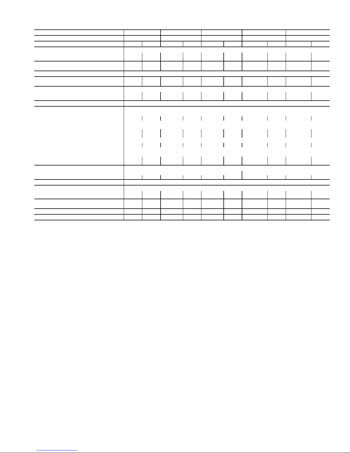
Table 1 — 38AP025-050 Unit Physical Data — English
38AP UNIT SIZE 025 027 030 040 050
NOMINAL CAPACITY, 50/60Hz (tons) 21/25 23/27 25/30 33/40 42/50
CIRCUIT Dual Single Dual Single Dual Single Dual Single Dual Single
OPERATING WEIGHTS (lb)
Standard 1095 1077 1258 1240 1264 1246 2094 1968 2120 1977
With Low Sound Option 1131 1113 1294 1276 1300 1282 2148 2022 2174 2031
APPROXIMATE REFRIGERANT CHARGE,
TYPICAL (lb)*
NITROGEN SHIPPING CHARGE 15 psig
COMPRESSOR
hp (Qty) (CKT A/CKT B)
CAPACITY STEPS
Standard 2222224343
Digital Option 22 22 22 22 22 22 44 33 44 33
CRANKCASE HEATER (W) (each compressor) 90
CONDENSER FANS
Standard Propeller Type - Direct Drive
Quantity 2222223333
RPM 1140 (60 Hz), 950 (50 Hz)
Diameter (in.) 30
Total Watts (60 Hz) 3300 3300 3300 3300 3300 3300 4200 4200 4200 4200
Total Watts (50 Hz) 2750 2750 2750 2750 2750 2750 3500 3500 3500 3500
Low Noise
Quantity 2222223333
RPM
Diameter (in.) 30
Total Watts (60 Hz) 2750 2750 2750 2750 2750 2750 3500 3500 3500 3500
Total Watts (50 Hz) 2300 2300 2300 2300 2300 2300 2900 2900 2900 2900
CONDENSER COIL MCHX Type
No. Coils per Circuit 11
sq ft 27.1 27.1 33.9 33.9 33.9 33.9 67.8 67.8 67.8 67.8
TEMPERATURE RELIEF Fusible Plug on Liquid Lines of Each Circuit - 210 F
CONNECTIONS (in.) ODF (CKT A/CKT B)
Suction Line 1
Liquid Line
MAXIMUM HEIGHT FOR 3° F SUBCOOLING
(ft)†
CAPACITY PER CIRCUIT (%) (CKT A/CKT B) 50/50 100 50/50 100 50/50 100 54/46 100 48/52 100
MINIMUM UNIT CAPACITY (%) 50 50 50 50 50 50 23 33 23 33
LEGEND
MCHX — Microchannel Heat Exchanger
ODF — Outside Diameter, Female
*Typical operating charge with 25 ft of interconnecting piping. Operating
charge is approximate for maximum system capacity. Unit is factory supplied
with nitrogen holding charge. Refrigerant charge for dual circuit units is the
total for both circuits.
†Maximum vertical separation between evaporator coil and condensing unit if
condensing unit is below the evaporator.
28 24 30 26 30 26 52 40 52 40
11 (2) 11 (2) 13 (2) 13 (2) 15 (2) 15 (2) 10 (2)/
8.5 (2)
13 (3) 11 (2)/
13 (2)
Shrouded Axial Fan - Direct Drive
850 (60 Hz), 700 (50 Hz)
3
/8 / 13/815/813/8 / 13/815/813/8 / 13/815/
5
/8 / 5/
5
5
/
8
/8 / 5/
8
5
5
/
8
/8 / 5/
8
8
15/8 / 15/
8
7
5
/
/8 / 5/
8
21/
8
8
15/8 / 15/
8
7
/
8
5
/8 / 5/
8
8
75 75 75 75 75 75 75 75 75 75
15 (3)
21/
7
/
8
8
3
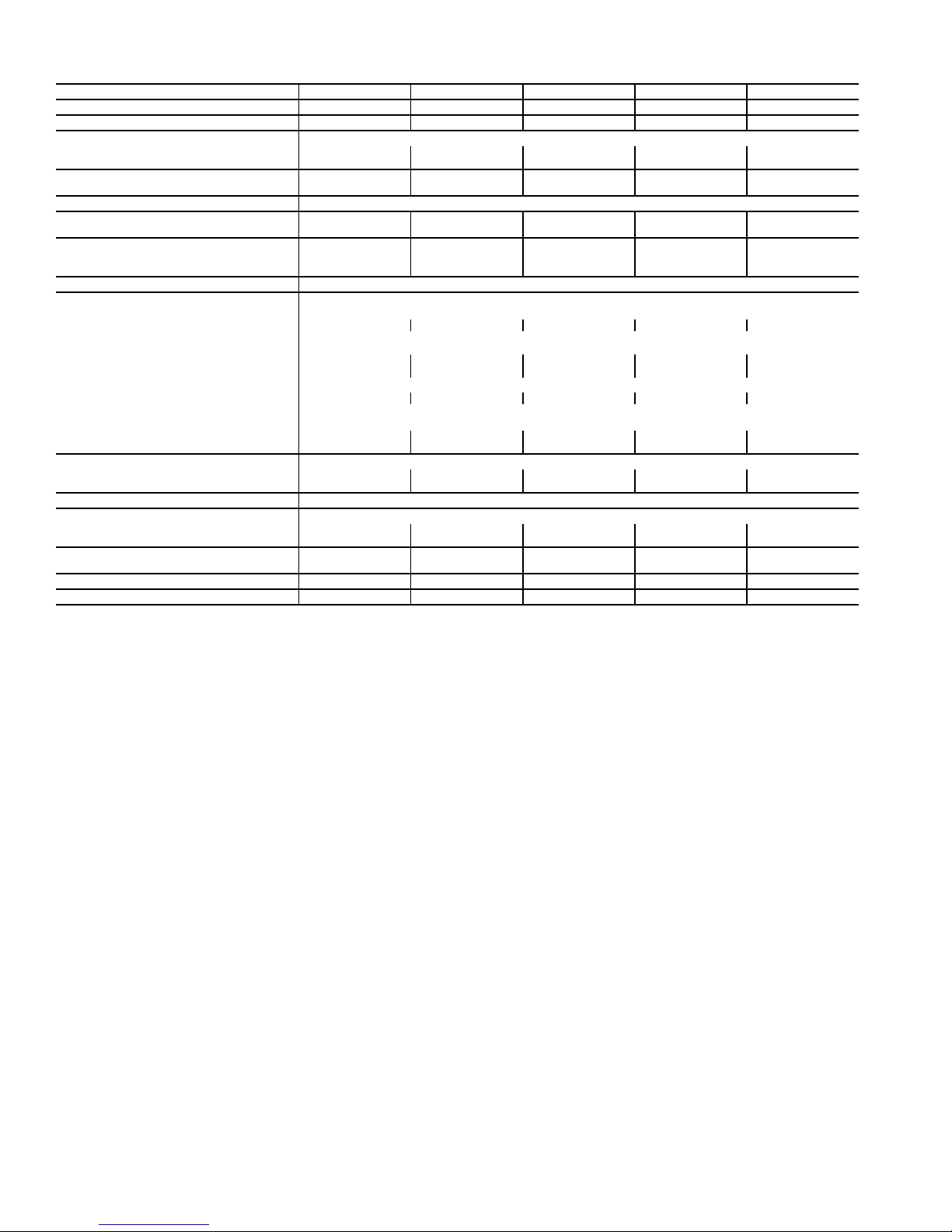
Table 2 — 38AP060-100 Unit Physical Data — English
NOMINAL CAPACITY, 50/60Hz (tons) 50/60 58/70 67/80 75/90 83/100
38AP UNIT SIZE 060 070 080 090 100
CIRCUIT Dual Dual Dual Dual Dual
OPERATING WEIGHTS (lb)
Standard 2227 2450 2610 2835 2844
With Low Sound Option 2299 2522 2700 2943 2952
APPROXIMATE REFRIGERANT CHARGE,
TYPICAL (lb)*
60 70 78 96 100
NITROGEN SHIPPING CHARGE 15 psig
COMPRESSOR
hp (Qty) (CKT A/CKT B)
CAPACITY STEPS
Standard 45566
Digital Option 44 55 55 66 66
13 (2)/15 (2) 15 (2)/11 (3) 15 (2)/15 (3) 13 (3)/15 (3) 15 (3)/15 (3)
CRANKCASE HEATER (W) (each compressor) 90
CONDENSER FANS
Standard Propeller Type - Direct Drive
Quantity 44566
RPM 1140 (60 Hz), 950 (50 Hz)
Diameter (in.) 30
Total Watts (60 Hz) 6200 6000 7500 9000 9000
Total Watts (50 Hz) 5150 5000 6250 7500 7500
Low Noise
Quantity 44566
RPM
Diameter (in.) 30
Total Watts (60 Hz) 5200 5000 6250 7500 7500
Total Watts (50 Hz) 4300 4150 5200 6250 6250
CONDENSER COIL MCHX Type
No. Coils per Circuit 1 2 2 to 3 3 3
sq ft 67.8 99.6 124.5 149.4 149.4
Shrouded Axial Fan - Direct Drive
850 (60 Hz), 700 (50 Hz)
TEMPERATURE RELIEF Fusible Plug on Liquid Lines of Each Circuit - 210 F
CONNECTIONS (in.) ODF (CKT A/CKT B)
Suction Line 1
Liquid Line
MAXIMUM HEIGHT FOR 3° F SUBCOOLING
(ft)†
5
/8 / 15/
5
/8 / 7/
8
8
15/8 / 21/
7
/8 / 7/
8
8
15/8 / 21/
7
/8 / 7/
8
8
21/8 / 21/
7
/8 / 7/
8
8
75 75 75 75 75
21/8 / 25/
7
/8 / 7/
8
8
CAPACITY PER CIRCUIT (%) (CKT A/CKT B) 46/54 47/53 40/60 46/54 50/50
MINIMUM UNIT CAPACITY (%) 23 24 20 15 17
LEGEND
MCHX — Microchannel Heat Exchanger
ODF — Outside Diameter, Female
*Typical operating charge with 25 ft of interconnecting piping. Operating
charge is approximate for maximum system capacity. Unit is factory supplied
with nitrogen holding charge. Refrigerant charge for dual circuit units is the
total for both circuits.
†Maximum vertical separation between evaporator coil and condensing unit if
condensing unit is below the evaporator.
4
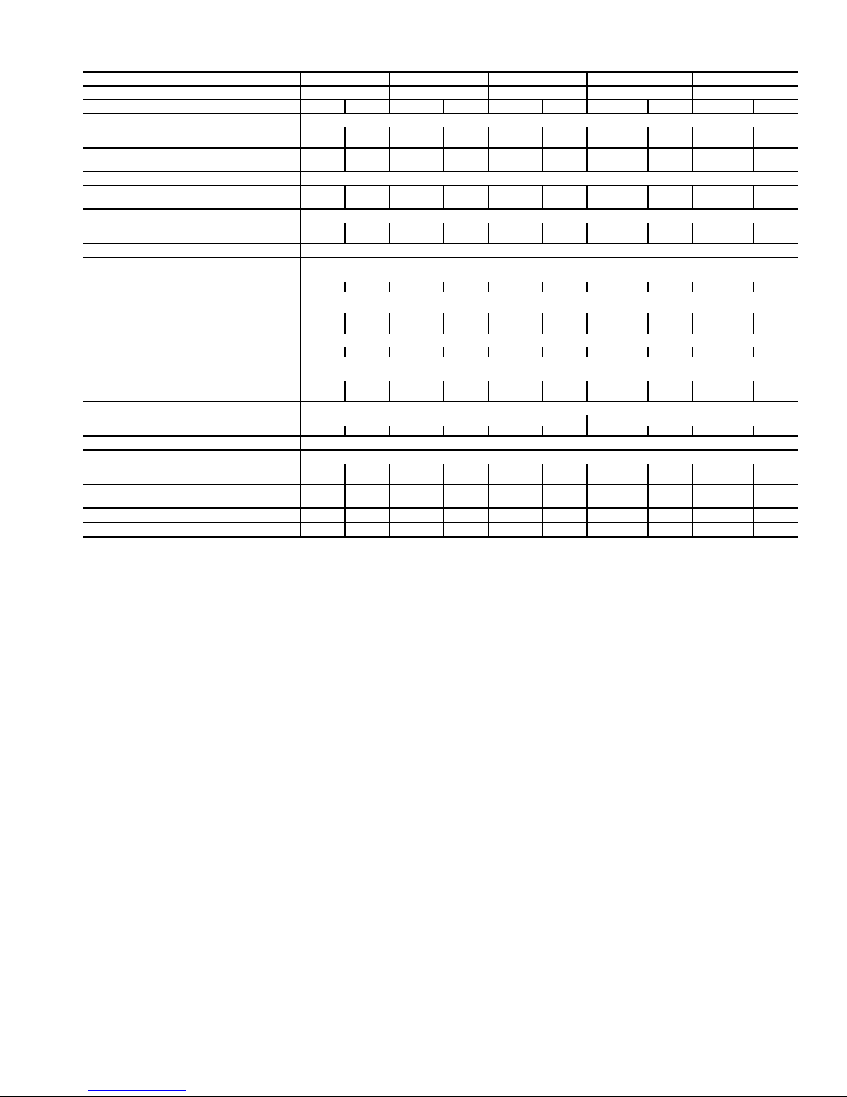
Table 3 — 38AP025-050 Unit Physical Data — SI
38AP UNIT SIZES 025 027 030 040 050
NOMINAL CAPACITY 50/60 Hz (kW) 74/88 81/95 88/106 116/141 148/176
CIRCUIT Dual Single Dual Single Dual Single Dual Single Dual Single
OPERATING WEIGHTS (kg)
Standard 497 489 571 562 573 565 950 893 961 897
With Low Sound Option 513 505 587 579 590 582 974 917 986 921
APPROXIMATE REFRIGERANT CHARGE,
TYPICAL (kg)*
NITROGEN SHIPPING CHARGE 1.03 bar
COMPRESSOR
kW (Qty) (CKT A/CKT B)
CAPACITY STEPS
Standard 222222 4 3 4 3
Digital Option 22 22 22 22 22 22 44 33 44 33
CRANKCASE HEATER (W) (each compressor) 90
CONDENSER FANS
Standard Propeller Type - Direct Drive
Quantity 222222 3 3 3 3
r/s 19 (60 Hz), 16 (50 Hz)
Diameter (mm) 762
Total Watts (60 Hz) 3300 3300 3300 3300 3300 3300 4200 4200 4200 4200
Total Watts (50 Hz) 2750 2750 2750 2750 2750 2750 3500 3500 3500 3500
Low Noise
Quantity 222222 3 3 3 3
r/s
Diameter (mm) 762
Total Watts (60 Hz) 2750 2750 2750 2750 2750 2750 3500 3500 3500 3500
Total Watts (50 Hz) 2300 2300 2300 2300 2300 2300 2900 2900 2900 2900
CONDENSER COIL MCHX Type
No. Coils per Circuit 11
sq m 2.5 2.5 3.2 3.2 3.2 3.2 6.3 6.3 6.3 6.3
TEMPERATURE RELIEF Fusible Plug on Liquid Lines of Each Circuit - 99 C
CONNECTIONS (in.) ODF (CKT A/CKT B)
Suction Line 1
Liquid Line
MAXIMUM HEIGHT FOR 1.7° C
SUBCOOLING (m)†
CAPACITY PER CIRCUIT (%) (CKT A/CKT B) 50/50 100 50/50 100 50/50 100 54/46 100 48/52 100
MINIMUM UNIT CAPACITY (%) 50 50 50 50 50 50 23 33 23 33
LEGEND
MCHX — Microchannel Heat Exchanger
ODF — Outside Diameter, Female
*Typical operating charge with 7.62 m of interconnecting piping. Operating
charge is approximate for maximum system capacity. Unit is factory supplied
with nitrogen holding charge. Refrigerant charge for dual circuit units is the
total for both circuits.
†Maximum vertical separation between evaporator coil and condensing unit if
condensing unit is below the evaporator.
12.7 10.9 13.6 11.8 13.6 11.8 23.6 18.1 23.6 18.1
8.2 (2) 8.2 (2) 9.7 (2) 9.7 (2) 11.2 (2) 11.2 (2) 7.5 (2)/
6.3 (2)
9.7 (3) 8.2 (2)/
9.7 (2)
11.2 (3)
Shrouded Axial Fan - Direct Drive
14 (60 Hz), 12 (50 Hz)
3
/8 / 13/815/813/8 / 13/815/813/8 / 13/815/
5
/8 / 5/
5
5
/
8
/8 / 5/
8
5
5
/
8
/8 / 5/
8
8
15/8 / 15/
8
7
5
/
/8 / 5/
8
21/
8
8
15/8 / 15/
8
7
/
8
5
/8 / 5/
8
8
23 23 23 23 23 23 23 23 23 23
21/
8
7
/
8
5
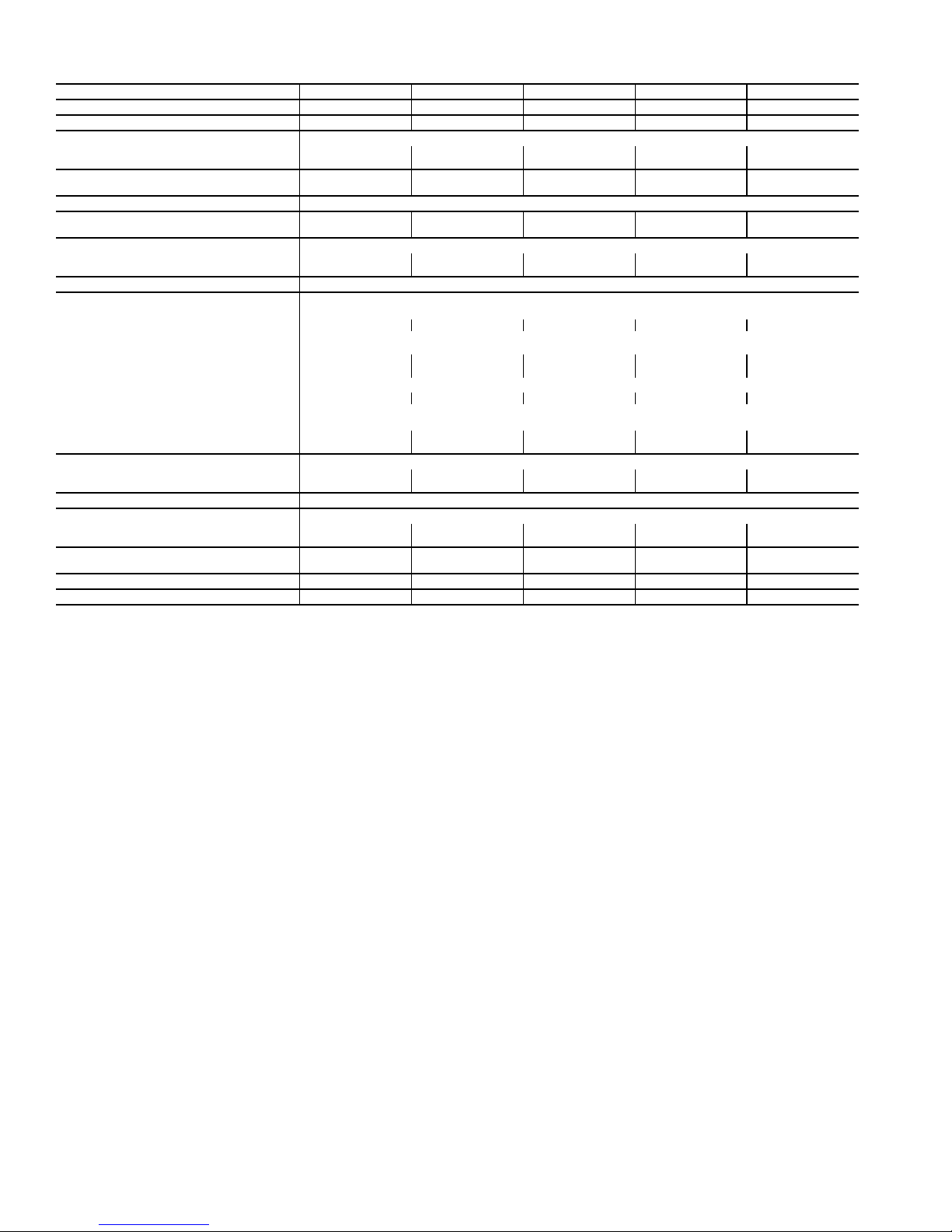
Table 4 — 38AP060-100 Unit Physical Data — SI
NOMINAL CAPACITY 50/60 Hz (kW) 176/211 204/246 236/281 264/317 292/352
38AP UNIT SIZES 060 070 080 090 100
CIRCUIT Dual Dual Dual Dual Dual
OPERATING WEIGHTS (kg)
Standard 1010 1111 1184 1286 1290
With Low Sound Option 1043 1144 1225 1335 1339
APPROXIMATE REFRIGERANT CHARGE,
TYPICAL (kg)*
27.2 31.8 35.4 43.5 45.4
NITROGEN SHIPPING CHARGE 1.03 bar
COMPRESSOR
kW (Qty) (CKT A/CKT B)
CAPACITY STEPS
Standard 45566
Digital Option 44 55 55 66 66
9.7 (2)/11.2 (2) 11.2 (2)/8.2 (3) 11.2 (2)/11.2 (3) 9.7 (3)/11.2 (3) 11.2 (3)/11.2 (3)
CRANKCASE HEATER (W) (each compressor) 90
CONDENSER FANS
Standard Propeller Type - Direct Drive
Quantity 44566
r/s 19 (60 Hz), 16 (50 Hz)
Diameter (mm) 762
Total Watts (60 Hz) 6200 6000 7500 9000 9000
Total Watts (50 Hz) 5150 5000 6250 7500 7500
Low Noise
Quantity 44566
r/s
Diameter (mm) 762
Total Watts (60 Hz) 5200 5000 6250 7500 7500
Total Watts (50 Hz) 4300 4150 5200 6250 6250
CONDENSER COIL MCHX Type
No. Coils per Circuit 1 2 2 - 3 3 - 3 3 - 3
sq m 6.3 9.3 11.6 13.9 13.9
Shrouded Axial Fan - Direct Drive
14 (60 Hz), 12 (50 Hz)
TEMPERATURE RELIEF Fusible Plug on Liquid Lines of Each Circuit - 99 C
CONNECTIONS (in.) ODF (CKT A/CKT B)
Suction Line 1
Liquid Line
MAXIMUM HEIGHT FOR 1.7° C
SUBCOOLING (m)†
5
/8 / 15/
5
/8 / 7/
8
8
15/8 / 21/
7
/8 / 7/
8
8
15/8 / 21/
7
/8 / 7/
8
8
21/8 / 21/
7
/8 / 7/
8
8
23 23 23 23 23
21/8 / 25/
7
/8 / 7/
8
8
CAPACITY PER CIRCUIT (%) (CKT A/CKT B) 46/54 47/53 40/60 46/54 50/50
MINIMUM UNIT CAPACITY (%) 23 24 20 15 17
LEGEND
MCHX — Microchannel Heat Exchanger
ODF — Outside Diameter, Female
*Typical operating charge with 7.62 m of interconnecting piping. Operating
charge is approximate for maximum system capacity. Unit is factory supplied
with nitrogen holding charge. Refrigerant charge for dual circuit units is the
total for both circuits.
†Maximum vertical separation between evaporator coil and condensing unit if
condensing unit is below the evaporator.
6
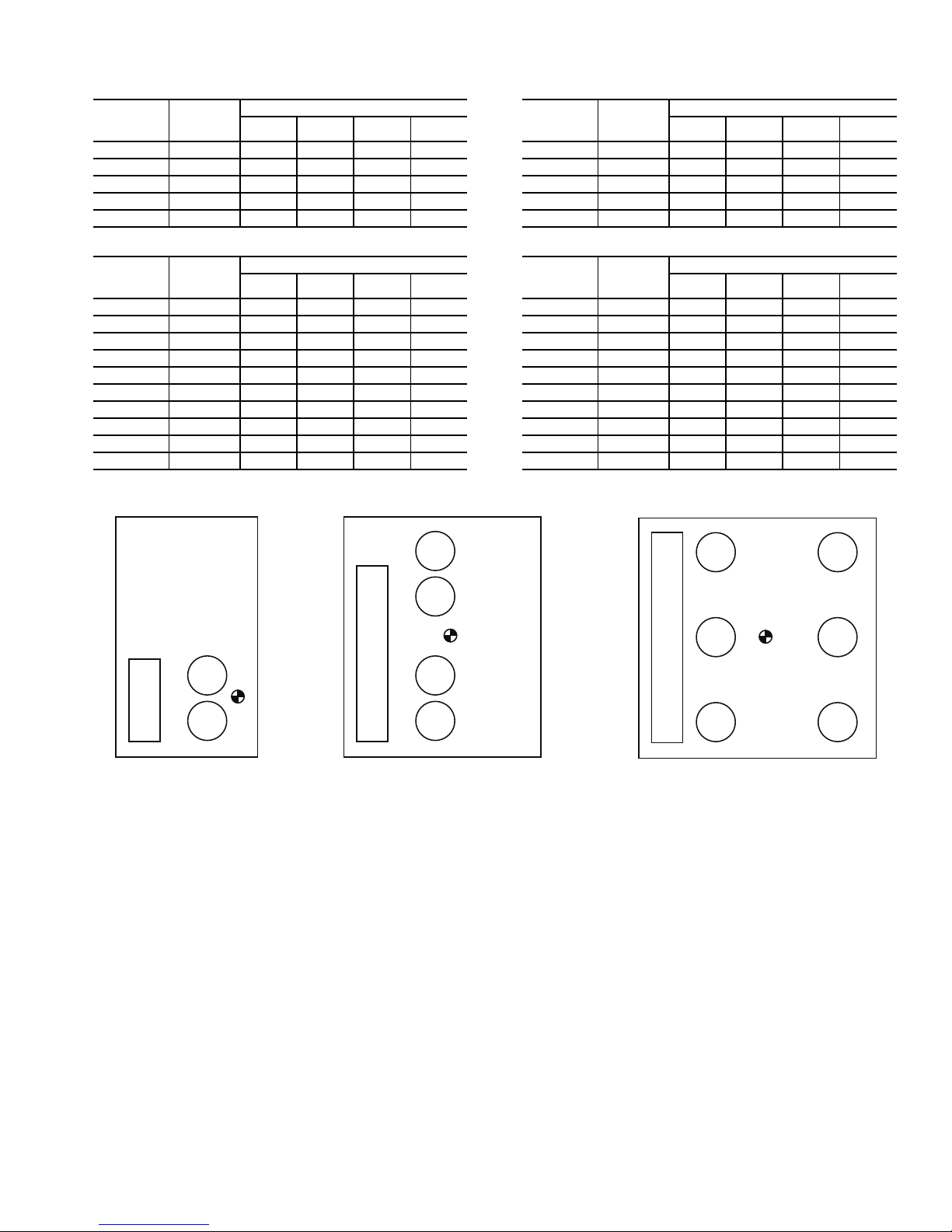
Table 5 — Operational Corner Weights with Refrigerant Charge (Approximate)
TOP VIEW, SIZES 070 TO 100
TOP VIEW,
SIZES 025 TO 030
TOP VIEW, SIZES 040 TO 060
Fig. 2 — Corner Weights
A
BC
D
COMP
COMP
CONTROL
BOX
A
BC
D
COMP
COMP
CONTROL BOX
COMP
COMP
A
BC
D
COMP
COMP
CONTROL BOX
COMP
COMP
COMP COMP
a38-7114
38APS Unit (lb)
38APS
UNIT
SIZE
025 1089 356 253 200 281
027 1255 396 291 240 327
030 1261 399 293 241 328
040 1998 619 616 380 382
050 2007 623 620 381 383
38APD
UNIT
SIZE
025 1107 360 258 204 285
027 1273 401 296 245 331
030 1279 404 297 245 333
040 2124 672 671 390 390
050 2150 683 684 392 391
060 2257 706 705 422 423
070 2494 723 620 532 620
080 2665 791 679 552 643
090 2901 759 750 692 700
100 2910 759 750 696 705
TOTAL
WEIGHT
TOTAL
WEIGHT
OPERATIONAL CORNER WEIGHT
ABCD
38APD Unit (lb)
OPERATIONAL CORNER WEIGHT
ABCD
38APS Unit (kg)
38APS
UNIT
SIZE
025 494 161 115 91 127
027 569 180 132 109 148
030 572 181 133 109 149
040 906 281 280 173 173
050 910 282 281 173 174
TOTAL
WEIGHT
OPERATIONAL CORNER WEIGHT
ABCD
38APD Unit (kg)
38APD
UNIT
SIZE
025 502 163 117 93 129
027 577 182 134 111 150
030 580 183 135 111 151
040 963 305 305 177 177
050 975 310 310 178 178
060 1024 320 320 192 192
070 1131 328 281 241 281
080 1209 359 308 250 292
090 1316 344 340 314 318
100 1320 344 340 316 320
TOTAL
WEIGHT
OPERATIONAL CORNER WEIGHT
ABCD
7
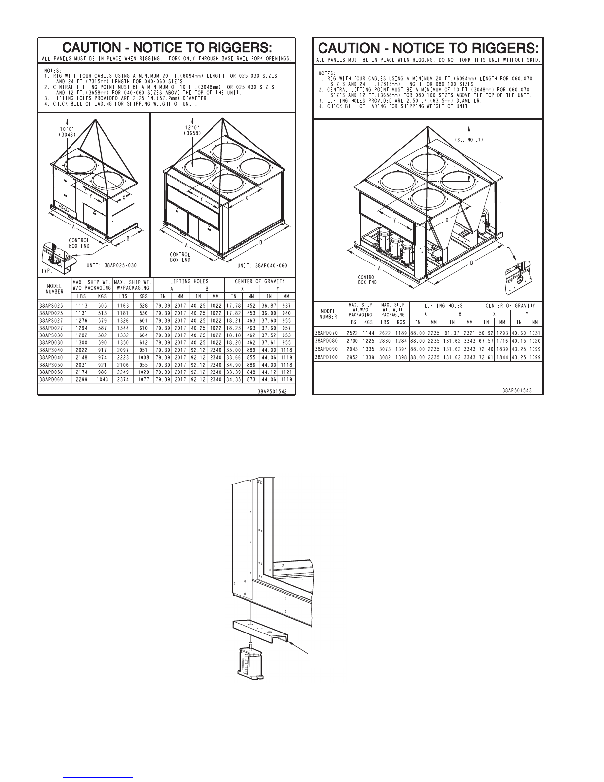
Fig. 3 — Rigging Labels
Fig. 4 — Perimeter Support Channel
SIZES 025 TO 060 SIZES 070 TO 100
a38-7115
a38-7116
LEGEND
ASTM — American Society for
Testing and Materials
a38-7130
4 x 24 in.
ASTM “C”
CHANNEL
8
UNIT
STANDARD
WEIGHT, lb (kg)
CENTER OF GRAVITY,
in. (mm)
HEIGHT,
in. (mm)
POWER ENTRY,
in. (mm)
SERVICE VALVE
CONNECTIONS, in. (mm)
X Y H P Suction Liquid
Standard
38APS025 1077 (489) 17.8 (452) 36.9 (937)
61.0 (1549) 24.9 (632)
1
5
/
8
(41)
5
/
8
(16)
38APD025 1095 (497) 17.8 (452) 37.0 (940) 1
3
/
8
(35)
5
/
8
(16)
38APS027 1240 (563) 18.2 (462) 37.6 (955)
73.1 (1857) 36.9 (937)
1
5
/
8
(41)
5
/
8
(16)
38APD027 1258 (571) 18.2 (462) 37.6 (955) 1
3
/
8
(35)
5
/
8
(16)
38APS030 1246 (565) 18.2 (462) 37.5 (953) 1
5
/
8
(41)
7
/
8
(22)
38APD030 1264 (573) 18.2 (462) 37.6 (955) 1
3
/
8
(35)
5
/
8
(16)
Low Sound
38APS025 1113 (505) 17.8 (452) 36.9 (937)
66.5 (1689) 24.9 (632)
1
5
/
8
(41)
5
/
8
(16)
38APD025 1131 (513) 17.8 (452) 37.0 (940) 1
3
/
8
(35)
5
/
8
(16)
38APS027 1276 (579) 18.2 (462) 37.6 (955)
78.6 (1996) 36.9 (937)
1
5
/
8
(41)
5
/
8
(16)
38APD027 1294 (587) 18.2 (462) 37.6 (955) 1
3
/
8
(35)
5
/
8
(16)
38APS030 1282 (582) 18.2 (462) 37.5 (953) 1
5
/
8
(41)
7
/
8
(22)
38APD030 1300 (590) 18.2 (462) 37.6 (955) 1
3
/
8
(35)
5
/
8
(16)
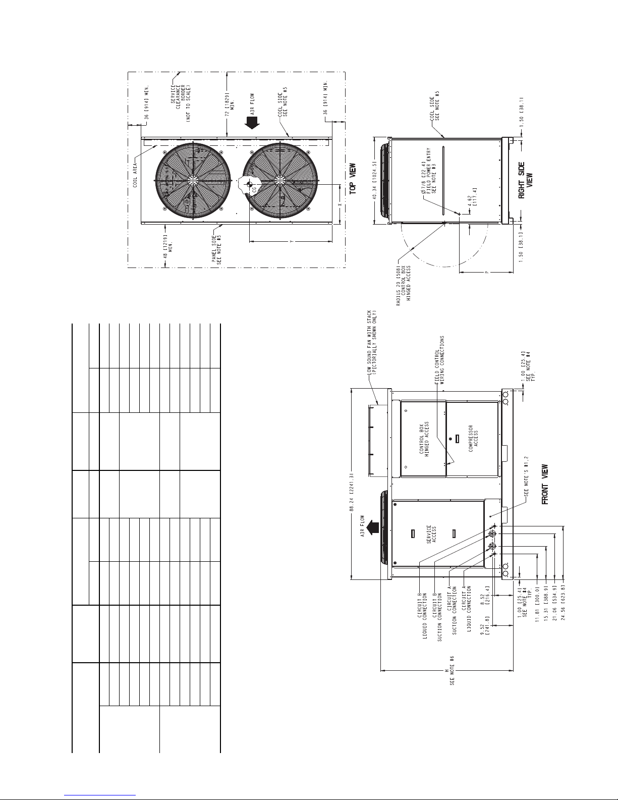
NOTES:
1. Be sure to use a wet rag to remove all valve cores before brazing field piping.
2. Do not cap or otherwise obstruct the liquid line temperature relief.
3. A
7
/
8
in. (22.4 mm) diameter hole is provided for locating field power wiring. Actual hole size
required depends on field wire sizing.
4. A 0.437 in. (11.1 mm) diameter hole is used for mounting unit.
5. Unit must have clearances as follows:
Top - Do not restrict.
Coil End - 72 in. (1829) from solid surface.
Panel Side - 48 in. (1219) per NEC (National Electrical Code, U.S.A. Standard).
6. Unit height dimension for standard and low sound unit with stack fan option.
7. Installation in a pit is not recommended.
8. Unit can be handled using the fork truck lift pockets.
9. Dimensions shown in inches (mm).
a38-7101
Fig. 5 — 38AP Unit Dimensions, Sizes 025-030
9
UNIT
STANDARD
WEIGHT, lb (kg)
CENTER OF GRAVITY,
in. (mm)
HEIGHT,
in. (mm)
SERVICE VALVE
CONNECTIONS, in. (mm)
X Y H Suction Liquid
Standard
38APS040 1968 (893) 35.0 (869) 44.0 (1118)
73.0 (1854)
2
1
/
8
(54)
7
/
8
(22)
38APD040 2094 (950) 33.7 (856) 44.1 (1120) 1
5
/
8
(41)
5
/
8
(16)
38APS050 1977 (897) 34.9 (886) 44.0 (1118) 2
1
/
8
(54)
7
/
8
(22)
38APD050 2120 (961) 33.4 (848) 44.1 (1120) 1
5
/
8
(41)
5
/
8
(16)
38APD060 2227 (1010) 34.4 (874) 44.1 (1120) 1
5
/
8
(41)
5
/
8
(16)
Low Sound
38APS040 2022 (917) 35.0 (869) 44.0 (1118)
78.5 (1994)
2
1
/
8
(54)
7
/
8
(22)
38APD040 2148 (974) 33.7 (856) 44.1 (1120) 1
5
/
8
(41)
5
/
8
(16)
38APS050 2031 (921) 34.9 (886) 44.0 (1118) 2
1
/
8
(54)
7
/
8
(22)
38APD050 2174 (986) 33.4 (848) 44.1 (1120) 1
5
/
8
(41)
5
/
8
(16)
38APD060 2299 (1043) 34.4 (874) 44.1 (1120) 1
5
/
8
(41)
5
/
8
(16)
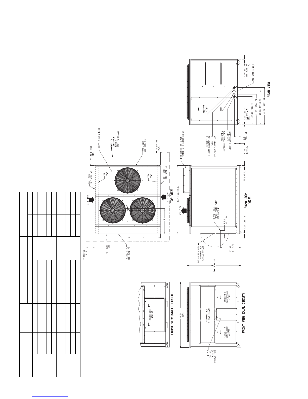
NOTES:
1. Be sure to use a wet rag to remove all valve cores before brazing field piping.
2. Do not cap or otherwise obstruct the liquid line temperature relief.
3. A
7
/
8
in. (22.4 mm) diameter hole is provided for locating field power wiring.
Actual hole size required depends on field wire sizing.
4. A 0.437 in. (11.1 mm) diameter hole is used for mounting unit.
5. Unit must have clearances as follows:
Top - Do not restrict.
Coil End - 72 in. (1829) from solid surface.
Panel Side - 48 in. (1219) per NEC (National Electrical Code, U.S.A. Standard).
6. Unit height dimension for standard and low sound unit with stack fan option.
7. Installation in a pit is not recommended.
8. Unit can be handled using the fork truck lift pockets.
9. Dimensions shown in inches (mm).
10. Sizes 040 and 050 units have 3 condenser fans. Size 060 units have 4 con-
denser fans.
a38-7102
Fig. 6 — 38AP Unit Dimensions, Sizes 040-060
10
UNIT
STANDARD
WEIGHT, lb (kg)
CENTER OF GRAVITY,
in. (mm)
HEIGHT,
in. (mm)
SERVICE VALVE CONNECTIONS,
in. (mm)
Suction
Liquid
X Y H Circuit A Circuit B
Standard 38APD070 2450 (1111) 50.9 (1293) 40.6 (1031) 73.0 (1854) 2
1
/
8
(54) 1
5
/
8
(41)
7
/
8
(22)
Low Sound 38APD070 2522 (1144) 50.9 (1293) 40.6 (1031) 78.5 (1994) 2
1
/
8
(54) 1
5
/
8
(41)
7
/
8
(22)
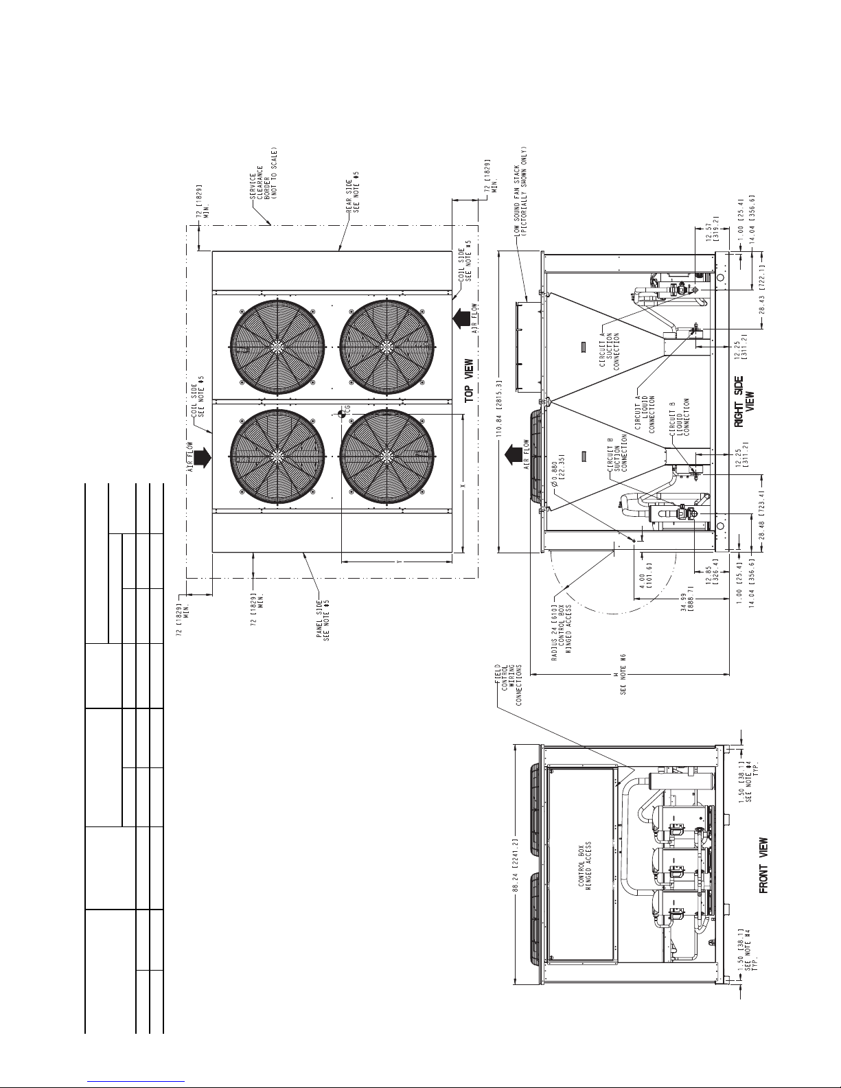
NOTES:
1. Be sure to use a wet rag to remove all valve cores before brazing field piping.
2. Do not cap or otherwise obstruct the liquid line temperature relief.
3. A
7
/
8
in. (22.4 mm) diameter hole is provided for locating field power wiring.
Actual hole size required depends on field wire sizing.
4. A 0.437 in. (11.1 mm) diameter hole is used for mounting unit.
5. Unit must have clearances as follows:
Top - Do not restrict.
Coil, Panel and Rear Side - 72 in. (1829) from solid surface.
6. Unit height dimension for standard and low sound unit with stack fan option.
7. Installation in a pit is not recommended.
8. Unit can be handled using crane.
9. Dimensions shown in inches (mm).
a38-7103
Fig. 7 — 38AP Unit Dimensions, Size 070
11
 Loading...