

Carpigiani UF 253 E Installation Manual
P.O. Box 4069 • Winston-Salem, NC 27115 • 336-661-9893 • 336-661-9895 (Fax)
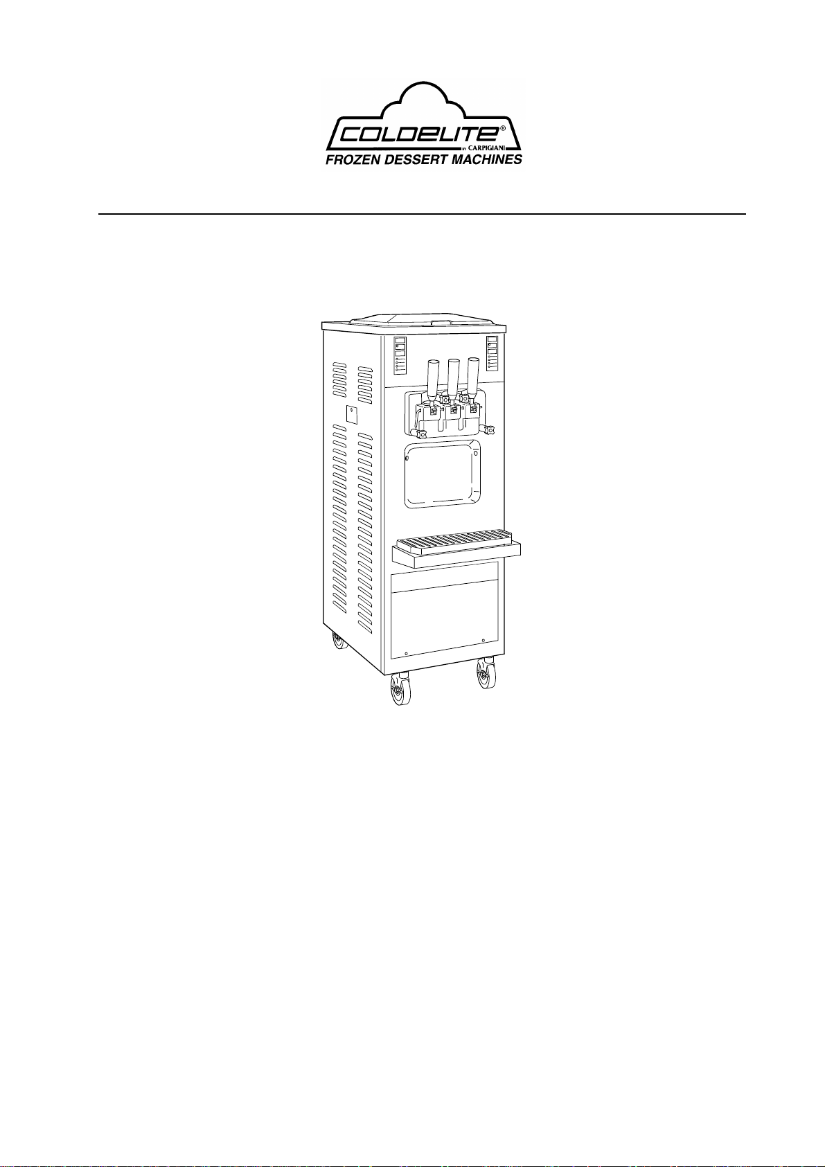
UF – 253 E Gravity and Pump
Soft Serve Freezer
Double Flavor Floor Model
OPERATION MANUAL

Foreword
Thank you for selecting Coldelite to meet your operation and growing
demands. Your Coldelite freezer has been manufactured utilizing the most advanced
technology and modern equipment available in the industry. We at Coldelite, take
great pride and care in the manufacturing of each and every freezer, using only the
finest components available, to provide you with many years of trouble free
operation.
Many years of experience in the manufacturing of soft serve dispensing
equipment have guided us in the preparation of this Operation Manual. PLEASE
READ IT CAREFULLY and keep it in an available place for future reference and
most of all, follow the instructions carefully.
On the following pages, you will find important information and procedures,
which describe the proper installation, sanitizing, operation, and maintenance of
your Coldelite freezer. We feel certain that your compliance with these instructions
will assure excellent performance, trouble-free operation and profitable business for
years to come.
2

Index
Foreword Page #
Part I Installation
A) Uncrating 4
B) Positioning the Machine 4-5
C) Electrical Requirements 5
D) Completing the Installation 5
Part II Explanation of Controls
A) Electronic Control Panel 6
B) Dispensing Handles 7
C) Proximity Switches 7
D) Dispensing Head Safety Switch 7
E) Electric Control Panel 7-8
F) Other Controls 8
Part III Initial Cleaning Procedure
A) Gravity Fed Cleaning Procedure 9
B) Pump Fed Cleaning Procedure 10
C) Disassembling the Dispensing Head 11
D) Disassembling the Beaters / Augers 12
E) Cleaning Operations 12
Part IV Assembling the Freezer
A) Assembling the Beaters / Augers 13-14
B) Assembling the Dispensing Head 14-16
C) Assembling the Gravity Feed Tubes 16-17
D) Assembling the Mix Injection Pumps 17-18
Part V Sanitizing the Freezer 19-20
Part VI Starting the Freezer
A) Gravity Fed Machines 21
B) Pump Fed Machines 22
Part VII Operating the Freezer
A) Stand By Mode 23
B) Gravity Fed Machines – How to Operate and Make Adjustments 24
C) Pump Fed Machines – How to Operate and Make Adjustments 24
Part VIII Periodic Cleaning Procedures
A) Gravity Fed Machines 25-26
B) Pump Fed Machines 26-28
Part IX Technical Information
A) Refrigeration 28
B) Beater Drive Motor 28
C) Thermal Overload 28
D) Proximity Switches 28
Part X Maintenance
A) Troubleshooting Guide 29-31
3
!! IMPORTANT !!
Failure to closely follow operational and
maintenance procedures may result in damage to
the unit and / or void your warranty. Coldelite
Corporation will not be responsible for any machine
not properly operated or maintained.
Part I – Installation
Before starting this procedure, ensure that the
shipping carton does not show any evidence of
damage due to dropping or mishandling. This may
indicate that the freezer was damaged during transit
or delivery.
!! IMPORTANT !!
Should the outside of the shipping carton give any
indication of possible damage, state this on the bill
of lading prior to signing. Contact the freight
carrier and request an inspection of damage. If this
procedure is not adhered to, you will forfeit your
rights to file a damage claim and be responsible for
subsequent repair costs.
Prior to choosing a location keep in mind that the
freezer should be accessible for periodic
maintenance and have adequate space for necessary
airflow.
Figure 1
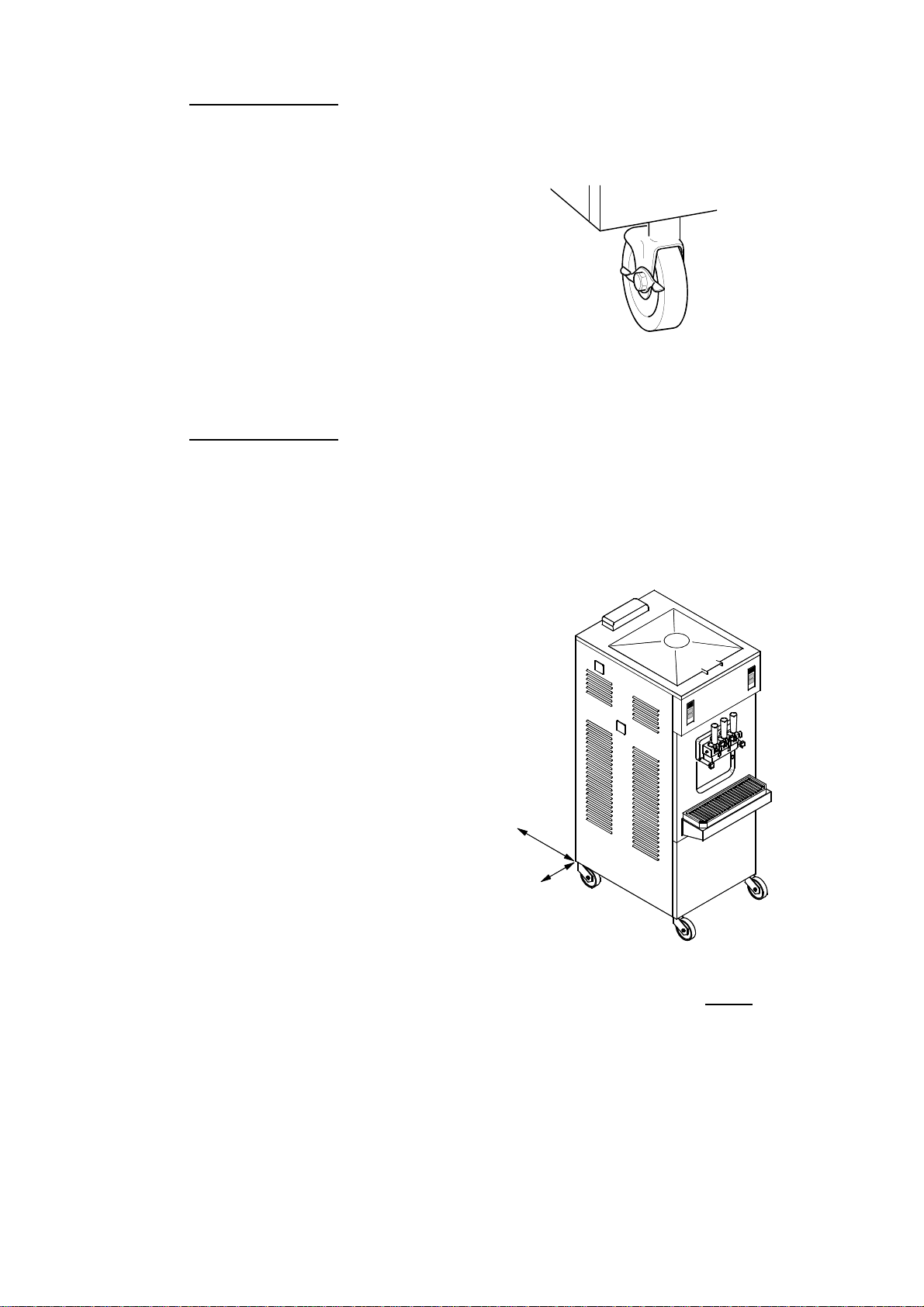
1) The freezer is equipped with pivoting casters to
allow for ease of movement. When placed in its
final location, lock the caster brakes to prevent
unwanted movement of the freezer. (Refer to Figure 1)
2) The freezer must also be level to ensure proper
drainage from the mix tanks and cylinders. To
level, place a level on all corners and shim the
casters as needed.
A)Uncrating the Freezer
1) The outer shipping carton is secured to the
shipping pallet with strapping. When cutting this
strapping, do so with caution as it may spring out
quickly. After cutting the strapping, lift the shipping
carton straight up and off of the freezer.
2) Remove the protective foam boards and plastic
wrapping from the outside of the freezer.
3) The freezer is also secured to the shipping pallet
with strapping. Again, exercise caution when
cutting this strapping since it may spring out
quickly.
4) You must now remove the side panels from the
freezer prior to lifting the freezer off of the pallet
with a lift truck. To remove the side panels, first
remove the side drip chutes and lower chute cover
on both side panels. Next remove the screws in each
side panel and gently pull down and away from the
machine frame. Remove the protective plastic
coating from the outer panel surfaces.
12"
4"
Figure 2
3) If your freezer is air cooled, you MUST have
adequate spacing on both sides and rear of the
machine. You should have a minimum of 4 inches
of clearance on both sides and 12 inches of
clearance on the rear of the machine. This will
ensure an adequate airflow is maintained.
(Ref. to Figure 2)
B) Positioning the Machine
After removing the machine from the shipping
pallet, it is now ready to be located in its final
location.
Note: If these clearances are not maintained, the
production capacity will be reduced, cycling will be
increased and the potential will exist that the machine
will stop completely
4

4) It is necessary to clean the air condenser each
month to remove dust, paper, etc., which may
obstruct airflow. Prior to cleaning the condenser
from the inside, disconnect the machines power
supply.
5) The machine should be connected to a fused
disconnect no more than six feet away. Electrical
installation MUST comply with state and / local
electrical codes.
6) Never position the machine in direct sunlight or
near a heat source. This will reduce its performance
and possible damage the freezer.
7) Water connections (Water Cooled Only)are made
at the rear of the machine. A minimum of ½ inch
(ID) water supply and drain lines are recommended.
Both the water inlet and outlet lines must remain
unobstructed or the machine performance will be
affected.
C) Electrical Requirements
All wiring installed to operate the freezer must be in
accordance with the National Electric Code and / or
local electrical codes and regulations.
!! IMPORTANT !!
This machine must be properly grounded.
Failure to properly ground the freezer may result
in dangerous and / or fatal electric shock.
The main machine power supply must meet
requirements at all times of operation. Voltage
fluctuations must not exceed plus or minus 5% of
the rated nameplate voltage.
All Coldelite machines are equipped with step down
transformers for the control circuit supply. These
transformers have a “multi-tap” input which must
be wired to match the inlet voltage
(ie. 208 or 230 vac). Failure to wire to the correct
supply voltage can result in machine malfunction.
Electrical Connection – ( Refer to Fig. 3 )
Having removed the side panels from the frame, the
main power connection box is located on the bottom
of the frame. The connection box is labeled
“Connect Power Line Here”. Connect the power
supply wires to the machines using the appropriate
electrical hardware and strain relief devices.
Figure 3
After the electrical connections are completed,
turn the power supply on. At this time you must
check the beater / auger motor rotation. The
correct beater rotation ( Facing the front of the
machine ) should be clockwise.
D) Completing the Installation
1) All of the setup and calibration of this freezer
should be performed by an approved Coldelite
Service Technician. Failure to calibrate this freezer
properly can result in freezer damage and a voided
warranty.
2) After installation and calibration of both
electrical and refrigeration circuits, the side panels
should be reinstalled.
!! IMPORTANT !!
Failure to closely follow factory setup and
maintenance procedures will result in a voided
warranty. Coldelite Corporation will not be
responsible for any freezer which is not setup or
maintained in accordance with factory procedures.
NOTE: Always turn the machine OFF and
disconnect the power supply switch to the freezer
prior to exposing any electrical connections or
moving parts.
On the following pages you will find important
information and procedures which describe the
proper sanitizing, operation, and maintenance of
your Coldelite Freezer. We are certain that your
full compliance with instructions and procedures
will result in many years of trouble free operation.
In the event this unit should malfunction or need
maintenance, please contact your local Coldelite
Distributor or Authorized Service Agent.
5
Part II – Explanation of Controls
A) Electronic Touch Pad – (Refer to figure 4)
888
L1
L2
L3
L4
L5
This machine is equipped with two independent
electronic touch control pads. Each electronic touch
pad operates one side of the freezer.
Indicator Lights – L1 through L4
These indicators illuminate to show the selected
machine function. When illuminated, the machine is
in that respective mode.
Indicator Light – L5
This light will illuminate when the mix tank is low
or out of mix. It is also possible to activate a low
mix level beeper in the programming mode.
Monitor – Position 570
This numerical monitor will display the cylinder
product consistency while the machine is freezing
product in the automatic mode. When not freezing
the product in the cylinder, it will display mix tank
temperature in ALL modes.
Stop / Reset – Position 571.1
When in this mode, the indicator light L1 will be lit
and the machine functions off. From this mode you
can access the programming mode or switch to
operating modes.
Push to Select – Position 571.2
By pressing this button you can select any of the
STOP
RESET
PUSH TO
SELECT
AUTOMATIC
STAND-BY
BEATER
MIX LEVEL
Figure 4
570
571.1
571.2
following machine modes:
- Automatic
- Stand-by
- Beater
The indicator light will illuminate corresponding to
the mode selected with the touch pad.
Automatic Mode
When placed in this mode the indicator light L2 will
illuminate and the machine will start the freezing
process in the cylinder. During this freezing process, a
number indicating the cylinder consistency will be
displayed (monitor #570, the lower the number, softer
the product). The machine will continue to freeze the
product in the cylinder (numbers will increase) until
the preset HOT number value is achieved. After
achieving the preset cylinder consistency number
(HOT) the machine will then start cooling the mix
tank and display mix tank temperature.
Stand-By Mode
When placed in this mode the indicator light L3 will
illuminate. This mode is used during prolonged idle
periods. The mix temperature in both cylinder and
mix storage tank is maintained below 40 degrees F by
the electronic temperature probes. Product should not
be served while in this mode as it will be too soft. The
Monitor (#570) will only display the temperature in
the mix tank while in this mode.
NOTE: If the mix level in the tank is below ½ full,
a warmer than actual temperature will be displayed
on the Monitor #570. The actual mix temperature
will remain at a safe temperature below 40 degrees F.
Beater Mode
When placed in this mode the indicator light L4 will
illuminate. This mode is used during the start-up
(pump fed), cleaning and sanitizing of the machine.
While in this mode the ONLY the beater / auger drive
motor will operate. This mode has a built in safety
device which will automatically switch the machine to
the stop mode after 15 minutes of operation. This
safety prevents an operator from inadvertently leaving
the freezer in this mode for extended periods of time,
which could damage the freezer.
Mix Tank Low Level Indicator
When low on mix in the mix storage tank, the
indicator light L5 will illuminate. This will indicate
that more mix is needed to operate the freezer. Each
mix tank has a maximum capacity of 18 quarts each.
DO NOT attempt to operate the freezer while low on
mix or your freezer may be damaged. It is also
possible to activate a beeper to sound when mix is
low in the Automatic and Stand-By modes. This is
done through the programming mode.
6
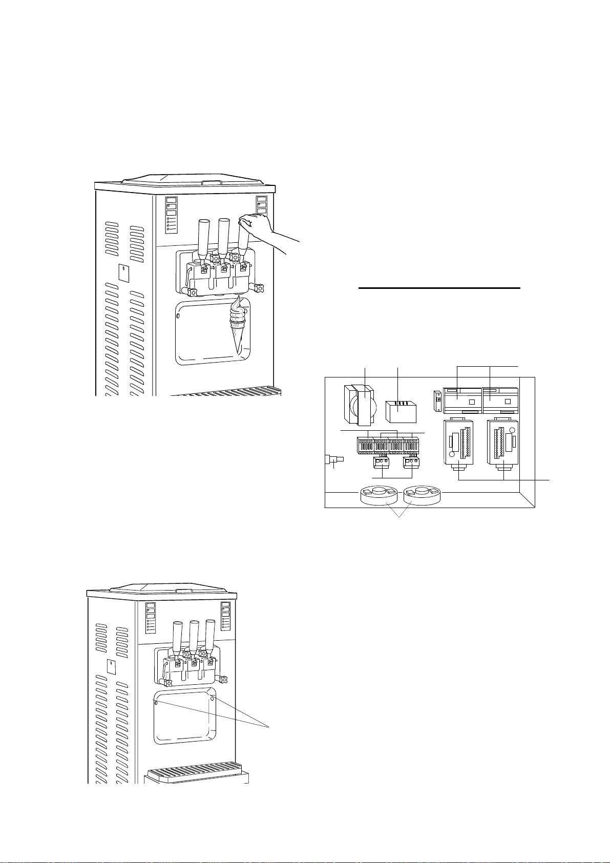
B) Dispensing Handles – (Refer to Figure 5)
The dispensing handles control the flow and
extraction rate of finished product. The left handle
serves product from the left cylinder, the right
handle serves product from the right cylinder and
the center dispenses equally from both cylinders.
You should ONLY dispense product when the
machine is in the automatic mode.
D) Dispensing Head Safety Switch
This machine is equipped with a dispensing head
safety switch. With the dispensing head removed,
the machine will not operate and Alarm 9 (AL9)
will appear on the front touch pad monitor. Please
refer to machine alarms on page 28 for more
details.
E) Electrical Control Panel – (Refer to figure
7)
The electrical control panel is located on the
bottom of the front panel. This control panel
contains all of the machines electrical control
components. ONLY a Coldelite Authorized
Technician should access this control panel.
!! IMPORTANT WARNING !!
Disconnect the freezer power supply before
opening the Electrical Control Panel and /
or servicing.
Figure 5
C) Photo Sensor Switches -(Refer to Figure 6)
In the Automatic mode the Photo Sensor Switches
(Position #920) activate the beater / auger motors
to dispense product. To activate the photo sensor
switches, simply place your hand with a cone or
cup under the dispensing head, pull the dispensing
handle and dispense product.
NOTE: You must activate the photo sensor switch,
starting the beater drive motor prior to dispensing
product.
4
2
6
8
1
3
7
5
Figure 7
The following is an explanation of some of the
components inside the electrical control panel.
1) Beater Motor Contactors - (Left /Right) –
Activates the beater drive motor. In the “BEATER”
mode, the contactor is energized by the front
switch pad. In the “AUTO” mode, the contactor is
energized by the photo sensor or
10 minute cycling timer.
5
Figure 6
920
2) Compressor Contactor – Activates the
refrigeration compressor. When the unit is in the
“AUTO” mode, the compressor contactor can be
energized by the electronic HOT setting or the Tev
Temperature probe. In the “Stand-By” mode, the
contactor is energized by the Tev and Tec
temperature probes.
7
3) Beater Motor Overload Protector - (Left/Right) –
Monitors the current draw of the beater drive
motor. If the motor draws excessive amperage, the
overload will trip and Alarm 1 (RtA) will be
displayed on the touch pad monitor.
4) Main Transformer – This transformer reduces
the incoming line voltage to 24 volts for the primary
control circuit.
5) Electronic Control Boards – (Left / Right) – These
boards control and monitor ALL functions of the
machine.
6) Safety Fuse – This fuse protects the high voltage
side of the main transformer in the event of a short
circuit. If tripped, all of the machines controls and
touch pads will be inoperative.
7) Current Monitoring Transformer – (Left / Right) –
These transformers monitor the current draw of the
beater drive motors.
8) Secondary Transformer – This transformer
reduces the voltage from 24 volts to 11 volts for the
electronic control circuit.
F) Other Controls
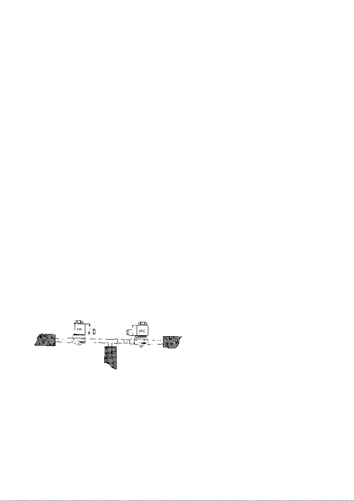
1) Refrigeration Solenoid Valves – These valves are
located behind the front panel. These valves are
used to control the flow of refrigerant to the
cylinders or mix storage tanks. These valves are
designated with EVC for each cylinder and EVV
for the mix storage tank. (Refer to Figure 8)
Figure 8
2) High Pressure Safety Switch – In the event of
restricted airflow (Air Cooled) or restricted water
flow (Water Cooled), this switch will turn off the
compressor contactor.
While tripped, the beater motors will continue to
run until the refrigerant pressure is reduced enough
to reset the safety switch. After resetting, both the
compressor and motor(s) will resume running.
8
Part III–Initial Cleaning Procedure
!! IMPORTANT !!
Before starting this procedure, place the machine in
the STOP mode on the touch pad.
This is a new machine and although clean, it must
be completely disassembled, washed and sanitized
before adding fresh product. Please proceed as
follows:
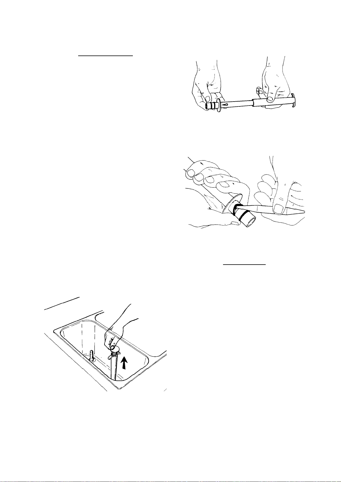
Next remove the outer regulating sleeve from the
center tube by pulling straight off.
1) Remove the mix tank cover and spare parts items
packed inside the mix tank. The spare parts kit will
include: spatula, cleaning brushes, sanitary
lubricant, oring removal tool, sanitizer packets,
spare orings and seals, and operation manual. Place
these items in a convenient place for future
reference.
Helpful Suggestion: Before proceeding with the
disassembly of the freezer, we recommend the use
of a clean plastic pan or pail to place the removed
parts into. This will minimize the possibility of
misplacing or damaging these components.
A) Gravity Fed Machines
Proceed with the disassembly process by removing
the gravity feed tubes, which are located inside each
mix storage tank. These should be pulled straight
up and out of the tanks.
Finally remove the orings on the end of the center
tube using ONLY the oring removal tool included
in your spare parts kit.
!! WARNING !!
Never use anything other than the oring remover
provided in your tool kit. Removing the orings with
other objects or tools can possibly damage the
orings and plastic parts.
Once removed, the gravity feed tubes must be
disassembled. To disassemble, first remove the
splash guard from the center of the tube.
9
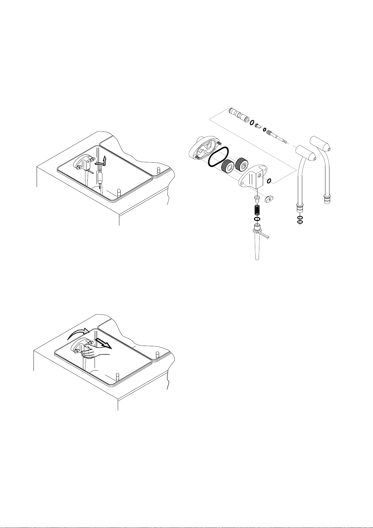
B) Pump Fed Machines
Proceed with the disassembly of the mix injection
pumps located in each mix storage tank. First slide
the connecting tube forward away from the mix
pump faceplate. This should free the feeding elbow
assembly from the pump assembly. Pull the feed
elbow assemblies straight up and out of each mix
storage tank.
Disassemble the mix pump assemblies as pictured
below (one per side). When disassembling the
orings from the other components, use only the
oring removal tool provided in the spare parts tool
kit. Using other tools to remove the orings from
their grooves can result in damaging both the oring
and component.
Next remove each mix pump assembly by rotating
clockwise until the hook stud on the rear of the
pump disengages from the pump hub. After
disengaging, slide the pump away from the rear of
the machine and out of the mix storage tank.
10
 Loading...