

Page 1
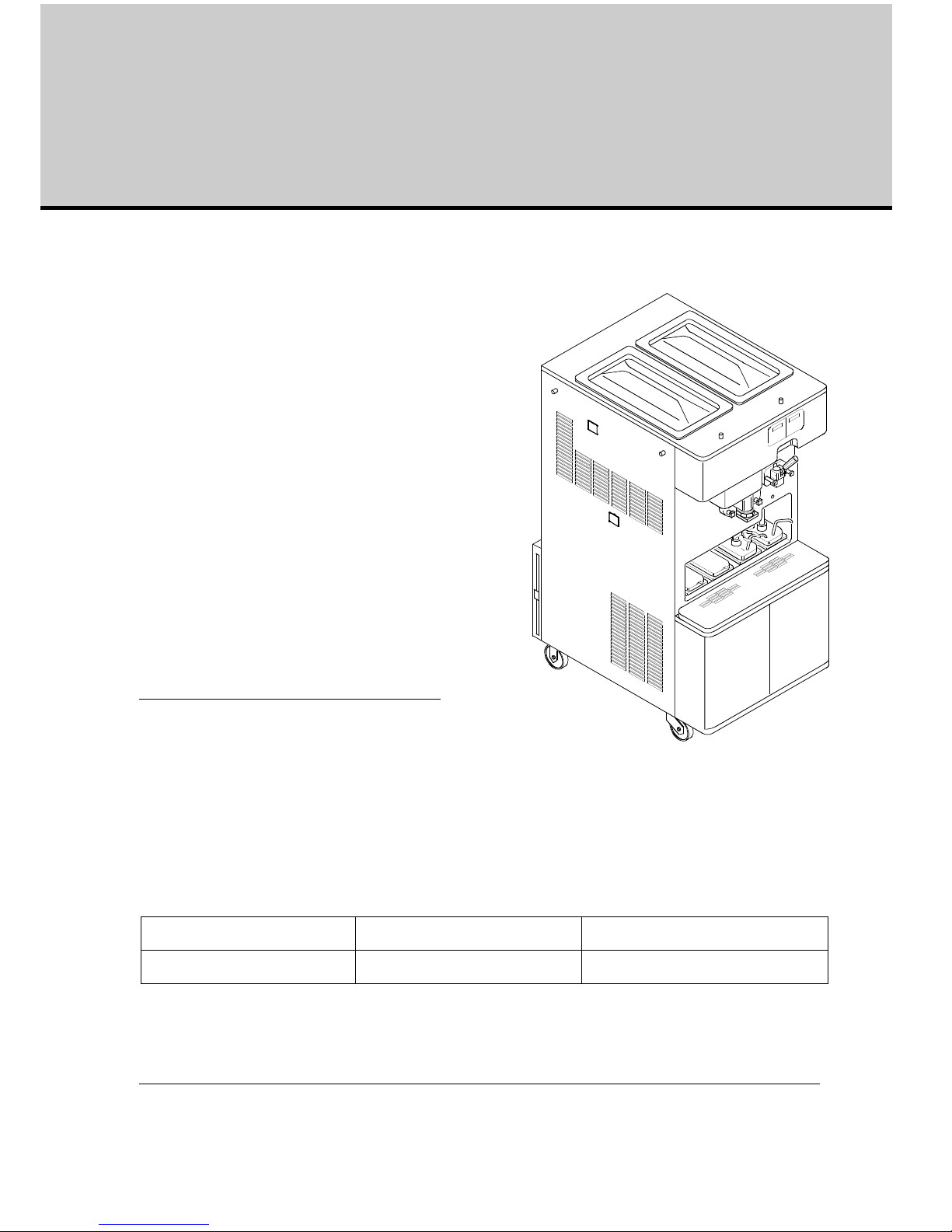
Combination shake/sundae dispenser K 3 – K3/E
Equipment Operating Manual
First Printing March 2006 Printed in Italy
Version 5: October 2012
Updates:
This manual is for the exclusive use of
licensees and employees of
McDonald’s Systems Inc
Manufactured by:
Carpigiani Group
Via Emilia, 45
Anzola dell'Emilia Bologna 40011
ITALY
Telephone:
Fax:
Edition:
5
Date:
10/2012
Modification: 1.2.9
Edited:
AM
Checked:
SB/AO
Approved;
RV
Page 2

Carpigiani K 3 User’s guide
This manual is for the exclusive use of licensees and employees of McDonald’s Systems Inc Page 2 of 63
Version 5: October 2012
Table of Contents
CONVENTIONAL SYMBOLS ..................................................................................................... 5
REMOVING MACHINE FROM PACKAGING .................... .................................................... 6
WEEE (WASTE ELECTRICAL AND ELECTRONIC EQUIPMENT) .................................. 7
TROUBLESHOOTING BACTERIA CONTAMINATION ...................................................... 7
1. INTRODUCTION ................................................................................................................... 9
1.1 GENERAL INFORMATION .................... ................................................ ....................... 9
1.1.1 MANUFACTURER'S IDENTIFICATION DATA .......................................................... 9
1.2 INFORMATION ABOUT THE MACHINE ............. ....................................................... 9
1.2.1 GENERAL DATA .......................................................................................................... 9
1.2.2 INTENDED USE ........................................................................................................... 9
1.2.3 NOISE ............................... ................................ ................................ ............................ 9
1.2.4 TECHNICAL FEATURES ..... ..................................................................................... 10
1.2.5 MACHINE ASSEMBLY IDENTIFICATION ............................................ ... ............... 10
1.2.6 AUTOMATIC PASTEURISATION CYCLE ................................................................ 11
1.2.7 TEMPERATURE CONTROL ...................................................................................... 11
1.2.8 TANK LIDS HOLDER ......................................... .. ................................... ... ............... 11
1.2.9 MIXER (OPTIONAL) .................................................................................................. 12
2. INSTRUCTIONS FOR USE ................................................................................................ 13
2.1 CONTROLS ................................ ..................... ..................... ...................... ..................... .. 13
2.1.1 MILK SHAKE FUNCTIONS ....................................................................................... 14
2.1.2 SUNDAE FUNCTIONS .............................................................................................. 19
2.2 OPERATIONS ................................................................................................................ 24
2.2.1 DISPENSING MILK SHAKE ...................................................................................... 24
2.2.2 DISPENSING SUNDAE ................................................. ................................... .......... 24
2.3 PROGRAMMED CLEANING CYCLE ......................................................................... 24
2.4 POWER BLACK- OUT .................................................................................................. 25
3. DAILY CLOSING PROCEDURES .................................................................................... 26
3.1 SHAKE SIDE .................................................................................................................. 26
3.1.1 DISASSEMBLING AND CLEANING THE COMPONENTS: ....................................... 26
3.1.2 SANITIZING THE DOOR AREA: ........................................................... .. ..................... 26
3.1.3 SYRUP LINE CLEANING / SANITIZING .............................. .. ................................... .. 26
3.1.4 PREPARING THE MACHINE FOR THE OVERNIGHT HEAT TREATMENT CYCLE.
27
3.1.5 FRONT PANEL CLEANING ......................................................................................... 27
3.2 SUNDAE SIDE ............................................................................................................... 28
3.2.1. SANITIZING THE DOOR AREA SURFACE: .................................................................. 28
3.2.2 TOPPING PUMPS CLEANING: .................................................................................. 28
3.2.3 PREPARING THE MACHINE FOR THE OVERNIGHT PASTEURISATION CYCLE. 28
3.2.4 FRONT PANEL CLEANING ......................................................................................... 28
Page 3

Carpigiani K 3 User’s guide
This manual is for the exclusive use of licensees and employees of McDonald’s Systems Inc Page 3 of 63
Version 5: October 2012
4.
DAILY OPENING PROCEDURES.................. .................................................................. 29
4.1 MILK SHAKE SIDE ....................................................................................................... 29
4.1.2 STARTING UP THE MACHINE: ..... ................................... .. ..................................... 29
4.2 SUNDAE SIDE ............................................................................................................... 30
4.2.1 SANITIZING THE DOOR AREA: ........................................................... .. ..................... 30
4.2.2 PREPARING HOT TOPPINGS: ................................................................................... 30
4.2.3 STARTING UP THE MACHINE: ................................................................................. 30
5. WEEKLY CLEANING ................................................... ................................... ... ............... 31
5.1 WASHING AND SANITIZING OF THE TOPPING CONTAINERS ........................... 31
5.1.1 CLEANING OF THE TOPPING BINS: ....................................................... .................. 31
5.1.2 CLEANING OFTHE TOPPING HOPPER ....................... ................................... .......... 31
5.2 DISASSEMBLING, WASHING AND SANITIZING OF THE HOT TOPPING PUMPS
31
5.3 CHECK TOPPING PUMP TEMPERATURE AND VOLUME ...................................................... 33
6. EVERY 14 DAYS CLEANING ........................................................................................... 34
6.1 DISASSEMBLING AND CLEANING THE MILK SHAKE SIDE ...................................... ............. 34
6.1.1 CLEANING THE SHAKE SYRUP SYSTEM .................................................................. 34
6.1.2 DRAINING AND CLEANING THE MILK SHAKE SIDE ................................ .......... 35
6.1.3 DISASSEMBLING OF THE SHAKE MIX PUMP ......................................... ... .......... 37
6.1.4 DISASSEMBLING OF THE SHAKE DISPENSING DOOR........ ............................... 38
6.1.5 DISASSEMBLING OF THE SHAKE CYLINDER’S BEATER ................................... 39
6.2 DISASSEMBLING AND CLEANING OF THE SUNDAE SIDE 40
6.2.1 DRAINING AND CLEANING OF THE SUNDAE SIDE ............................................ 40
6.2.2 DISASSEMBLING OF THE MIX PUMP................................................................. 42
6.2.3 DISASSEMBLING OF THE SUNDAE DISPENSING DOOR ................................... 43
6.2.4 DISASSEMBLING OF THE SUNDAE BEATER .............................. .......................... 43
6.3 WASHING AND SANITIZING OF COMPONENT PARTS ........................................ ..... ...... .. ..... 44
6.4 REASSEMBLY OF WASHED AND SANITIZED COMPONENT PARTS ................ 46
6.4.1 REASSEMBLY OF THE SHAKE CYLINDER BEATER ............................................. 46
6.4.2 REASSEMBLY OF THE SHAKE DISPENSING DOOR................ ... .......................... 47
6.4.3 REASSEMBLY OF THE SHAKE MIX PUMP ....................................................... ... .. 48
6.4.4 REASSEMBLY OF THE MIX HOPPER AGITATOR ............................................. 50
6.5 REASSEMBLY OF WASHED AND SANITIZED COMPONENT PARTS ..................... 50
6.5.1 REASSEMBLY OF THE SUNDAE BEATER ....................................... ....................... 50
6.5.2 REASSEMBLY OF THE SUNDAE DISPENSING DOOR .......................................... 50
6.5.3 REASSEMBLING OF THE SUNDAE MIX PUMP ..................................................... 51
6.5.4 REASSEMBLING OF THE MIX TANK AGITATOR .................................................. 52
6.6 SANITIZING OF THE ENTIRE MACHINE ................................................................. 52
6.6.1 SANITIZE THE HOPPER ......................... .................................................................. 52
6.6.2 SANITIZE THE PUMP AND FREEZING CYLINDER ............ ... ............................... 52
6.6.3 DRAIN THE SANITIZER ............................................................................................ 52
6.7 SYRUP SANITIZING, PRIMING AND CALIBRATION (SHAKE SIDE) ...................... ..... 53
6.8 MIX PRIMING ................................ ................................................ ............................... 54
7. MONTHLY CLEANING ..................................................................................................... 55
7.1 CLEAN MESH FILTERS (ONLY FOR AIR COOLED VERSION) ............................. .................. 55
Page 4

Carpigiani K 3 User’s guide
This manual is for the exclusive use of licensees and employees of McDonald’s Systems Inc Page 4 of 63
Version 5: October 2012
8.
PREVENTATIVE MAINTENANCE ................................................................................. 56
8.1 CHECK OUT LIST ......................................................................................................... 56
8.2 PERIODICAL CHECK-UP AND MAINTENANCE ......................................................... 57
8.2.1 PERISTALTIC PUMP TUBE REPLACEMENT INSTRUCTION ..................... ............................... 57
9. TROUBLESHOOTING ........................ ................................ .................................. ............. 59
9.1 ALARMS ........................................................................................................................ 59
FOLLOWING FIND THE ALARM LIST: ..................... ................................... .. ..................... 59
Page 5
Carpigiani K 3 User’s guide
This manual is for the exclusive use of licensees and employees of McDonald’s Systems Inc Page 5 of 63
Version 5: October 2012
Conventional Symbols
ATTENTION ELECTRIC SHOCK DANGER
The staff involved is warned that the in observance of safety rules in carrying out the
operation described may cause an electric shock.
ATTENTION GENERAL DANGER
The staff involved is warned that the operation described may do harm if not carried ou t in
the observance of safety rules.
NOTE
It points out significant information for the staff involved.
WARNING
The staff involved is warned that the in observance of information may cause a loss of data
and damages to the machine.
PROTECTIONS
This symbol placed by description side means that the operator must use personal
protections against an implicit risk of accident.
SAFETY
When using industrial equipment and plants, one must be aware of the fact that drive
mechanisms (rotary motion), high voltage of the components, as well as parts subject to high
temperatures may cause serious damages to persons and things.
The person in charge for plant’s safety must be on the look-out that
- an uncorrect use or handling is avoid ed
- Safety devices must neither be removed nor tampered
- Only original spare parts are to be used especially as far as those components with safety functio ns are
concerned (ex.: protection microswitche s, thermostats).
To achieve the above, the following is necessary:
- At working place an instruction manual relevant to the machine should be available.
- Such documentation must be carefully read and regulations must consequently be followed.
- Only adequately skilled personnel will have to be assigned to electrical equipment.
WARNING
The machine must be installed only by a specialized and authorized technician; when
installing the machine, insert a differential magnetothermal protection switch on all poles of
the line, adequately sized to the absorption power shown on machine data plate and with
contact opening of 3 mm at least. This switch is used to cut off the power supply. Any
replacement of the power cable must be carried out only by a specialized and authorized
technician.
Never put your hand into the machine, during production and cleaning opera tions. Before carrying
out any maintenance operation, make sure that the machine is in “STOP” position and main switch
has been cut out.
It is forbidden to wash the machine by means of a stream of water under pressure.
Disconnect electrical power before removing any side or rear panel.
CARPIGIANI is not responsible for any accident that might happen during operation, cleaning
and/or servicing of its units, if this warning has not been fully complied with.
Page 6
Carpigiani K 3 User’s guide
This manual is for the exclusive use of licensees and employees of McDonald’s Systems Inc Page 6 of 63
Version 5: October 2012
Removing machine from packaging
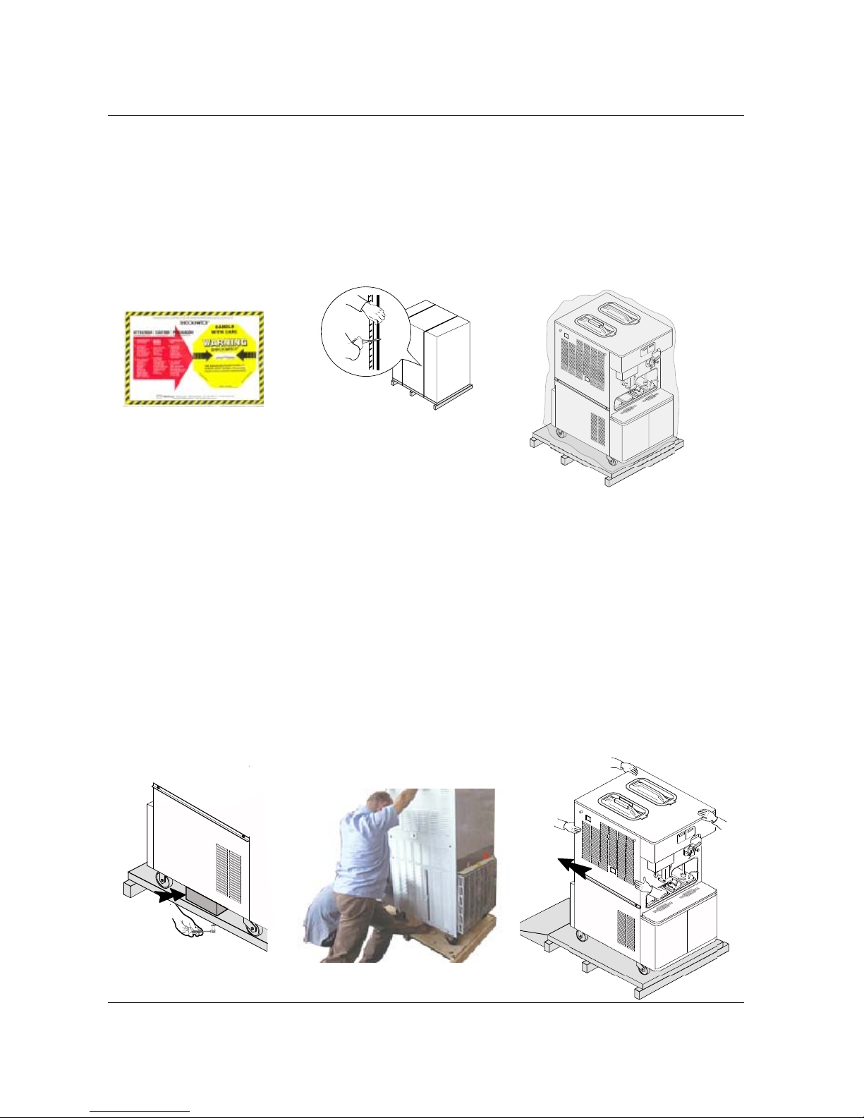
1. Check the Shock-watch label which indicates whether the goods have been mishandled; inspe ct
the cardboard shipping carton for signs of damage. (See fig.1)
2. Cut the metal straps (beware of snapping metal), lift the cardboard carton up and off of the pallet (see picture
2).
3. Remove bag and Styrofoam protection. Inspect the machin e again for signs of sh ipping damage o r
rough handling. If damage is visible, notify the rest aurant manager and/or the shipping company
(see fig. 3).
Fig. 1 Fig. 2
Fig. 3
CAUTION
removal from the pallet must be carried out by two qualified persons in material handling and in the
observation of safety rules.
4. The machine is attached to the pallet by 4 bolts. The bolt heads are on the bottom side of the pallet and
they tighten into threaded holes on the bottom of the machine. The two wooden shims, pl aced sideways
under the machine, make it possible to keep the wheels ¼" of the surface of the pallet (see fig. 4).
5. Now loosen the packing bolts from the bottom side of the pallet, on one side only, and let them drop to
the floor. It is not necessary to remove the side panels of the machine to do this (see fig. 4).
6. Slightly, incline the machine on one side and remove the wooden block. Please be careful. The wood blocks
keep the machine castors off the pallet by ¼" their removal will cause the machine to drop that distance (see
fig. 5).
7. Repeat the same procedure on the other side.
8. After the removal of the wooden blocks, the machine will directly rest with its wheels on the pallet.
9. In order to unload the machine from the pallet, use the woo den ramps, su pplied with the m achine. Place the
wooden ramps in position against the rear side of the machine and push the machine from FRONT SIDE
moving it to the rear. Two persons, one in front and one in the rear, must handle and control the unit (see fig. 6).
Fig. 4 Fig. 5 Fig. 6
Page 7
Carpigiani K 3 User’s guide
This manual is for the exclusive use of licensees and employees of McDonald’s Systems Inc Page 7 of 63
Version 5: October 2012
WEEE (Waste Electrical and Electronic Equipment)
In accordance with European Directives 2006/66CE on batteries and accumulators and waste batteries
and accumulators and with 2002/96/EC on WEEE (Waste Electrical and Electronic
Equipment), the presence of the above symbol on the product or on its packaging
indicates that this item must not be disposed of together with the other normal unsorted
municipal waste. Instead, it is the user’s responsibility to dispose of this product by
returning it to a collection point designated for the recycling of electrical and electronic
equipment waste. Separate collection of this waste helps to optimise the recovery and
recycling of any reclaimable materials and also reduces the impact on human health
and the environment.
For more information concerning the correct disposal of this product, please contact
your local authority or the retailer where this product was purchased.
Troubleshooting Bacteria Contamination
Product samples should be taken periodically by a qualified expert in order to asses the
bacteria count in the product. The bacteria count in the samples should be below the
figures given below:
Standard Plate Count (SPC)……………...50,000
Coliform …………………………………………10
Should the bacteria counts exceed the figures listed above then there is a source of bacterial
contamination. The source of contamination must be identified and corrected. High bacteria counts are
indicate that a product is not safe for consumption. You must inform the machine operator on how to
prevent bacterial contamination of the product.
Note: Soft serve yogurt
will generally have high bacteria counts – this is normal and helps define the
product. However, COLIFORM bacteria contamination is NOT ACCEPTABLE in any food product. The
information given below will help prevent coliform bacteria contamination problems.
The following is a list of possible bacteria contamination sources together with methods of
prevention.
SOURCE OF
CONTAMINATION
PREVENTION
1 - Operator contact.
1a - Wash hands and forearms thoroughly.
1b - Wear rubber gloves if cuts or skin conditions exist.
1c - Wash hands periodically throughout the day.
2 - Mix residue/deposits (milkstone
build-up).
2a - Provide the proper brushes.
2b - Thoroughly brush clean all parts and components to
prevent the formation of milkstone, a porous substance
which will house bacteria and contaminate fresh mix.
Page 8

Carpigiani K 3 User’s guide
This manual is for the exclusive use of licensees and employees of McDonald’s Systems Inc Page 8 of 63
Version 5: October 2012
SOURCE OF
CONTAMINATION
PREVENTION
3 - Worn or damaged parts.
3a - Lubricate all rubber parts contacting the mix with a food
grade lubricant.
3b - Inspect o-rings for damage. Only replace with factory
approved parts.
3c - Regularly check drip troughs for excessive leakage.
4 - Incorrect cleaning and sanitation
procedures.
4a - Sink must be perfectly clean and contain enough solution
to cover the biggest component. Brush clean and sanitize
the freezer on a regular basis.
4b - Use the correct brushes, lubricants, and single service
towels.
4c - Store and use chemicals as directed by the instructions on
their labels.
4d - Use a few good employees to follow the cleaning
procedure correctly and consistently. Allow the employee
uninterrupted time to complete the cleaning procedure.
4e - Allow the sanitizing solution to stand in the hopper and
freezing cylinder for five minutes.
4f - Wash and sanitize the lubricant tube after each use.
Always replace the cap on the tube.
4g - Machine components and brushes should be air-dried
overnight. Never store them in the storage cooler.
4h - Always follow daily cleaning procedures. Regularly wipe
down the outside of the machine and dispensing spouts
with a sanitized towel.
5 - Improperly stored mix
5a - Use mix stock with oldest date first. Observe expiration
dates.
5b - Place the mix directly in the cooler. Do not stack mix
outside or under direct sunlight before placing it in the
cooler.
5c - Always leave one inch between the mix and other products
in the cooler to allow air to circulate.
5d - Mix must not remain at room temperature for long periods
of time.
5e - Hopper storage must maintain a temperature of 40°F
(4,4°C). Storage temperatures above 45°F will allow
bacteria to multiply to dangerous levels in less than one
hour.
5f - Once the mix is placed in the hopper, the ho pper covers
must be used to maintain the correct temperature and
minimize mix contamination.
Page 9
Carpigiani K 3 User’s guide
This manual is for the exclusive use of licensees and employees of McDonald’s Systems Inc Page 9 of 63
Version 5: October 2012
1. Introduction
1.1 GENERAL INFORMATION
1.1.1 MANUFACTURER'S IDENTIFICATION DATA
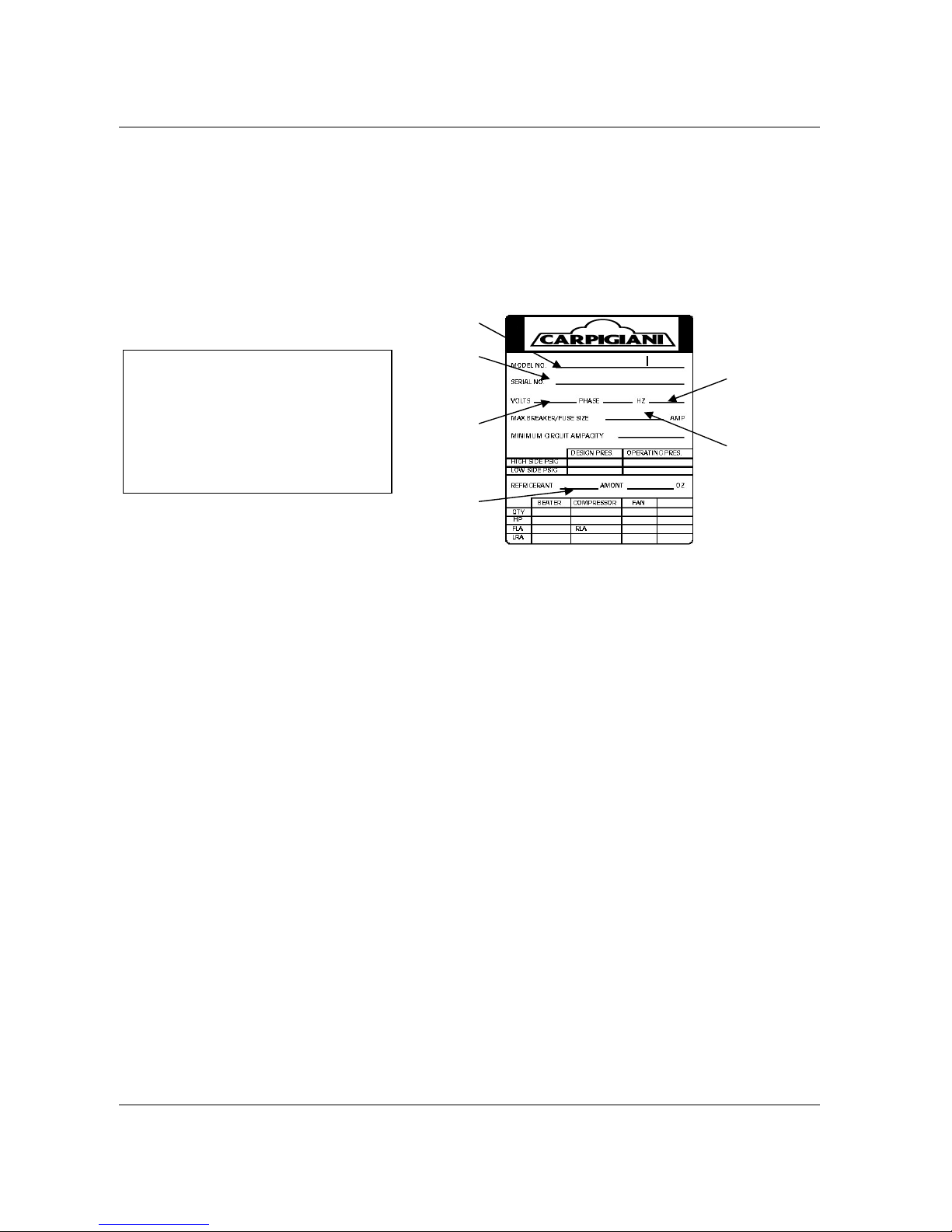
The machine has a data plate carrying manufacturer data, machine type and serial number, assigned
when it is manufactured.
1.2 INFORMATION ABOUT THE MACHINE
1.2.1 GENERAL DATA
Electronic, self-heat-treatment, floor machine, for the production and immediate distribution of
milkshake/ice cream having the following main features:
Refrigerated upper tanks;
Cylinder feeding pumps (to control product overrun);
Automatic system to dispense the milkshake with a 4 flavours syrup selection;
Two containers for hot toppings, with pasteurisation temperature control;
Two containers for room temperature toppings;
Automatic pasteurisation system to heat-treatment the product inside the mix tank and inside the
cylinder during pause periods (for instance, during night time);
Electronic consistency control system hard-o-matic.
1.2.2 INTENDED USE
The K 3 machine must only be used for the production of ice cream and milkshake, within th e functional
limits listed below:
Voltage: ±10%
Min. ambient temperature: 50°F (10°C)
Max. ambient temperature: 109°F (43°C)
Max relative ambient humidity: 85%
This machine has been designed for its use in closed places not subject to explosion-proof standards;
consequently, it shall be used in places complying with normal atmosphere..
1.2.3 NOISE
The continuous level of acoustic radiation pressure, which has been weighed and called A on working
place, turns to be lower than 70 dB(A), both by air-cooled and water-cooled units.
LEGEND:
A= Serial number
B= Machine type
C= Voltage
D= Fuss/Breaker size
E= Gas type and weight
F= Frequency
A
B
C
E
F
D
Page 10
Carpigiani K 3 User’s guide
This manual is for the exclusive use of licensees and employees of McDonald’s Systems Inc Page 10 of 63
Version 5: October 2012
1.2.4 TECHNICAL FEATURES
Model
Hour ly Produ ction * Hopper capacity Flavors Electrical supply
Installed
power
Full
load
Net
weight
lb / kg
SUNDAE SHAKE
SUNDAE
Gallons
Liters
TTS
Galons
Liters
SUNDAE SHAKE Volt - V Phase Cycle - Hz kW Amps
lb /kg
3,5 oz. / 100 gr
portions
lb / kg
13,5 oz. / 400 ml
portions
K 3
K3/E
82 / 38 380 88 / 40 160
5,25 gal
20 l
5,25 gal
20 l
1 5
208 - 230 3 60 5,5 30
871 / 395
380 - 415 3 50 5,5 20
1.2.5
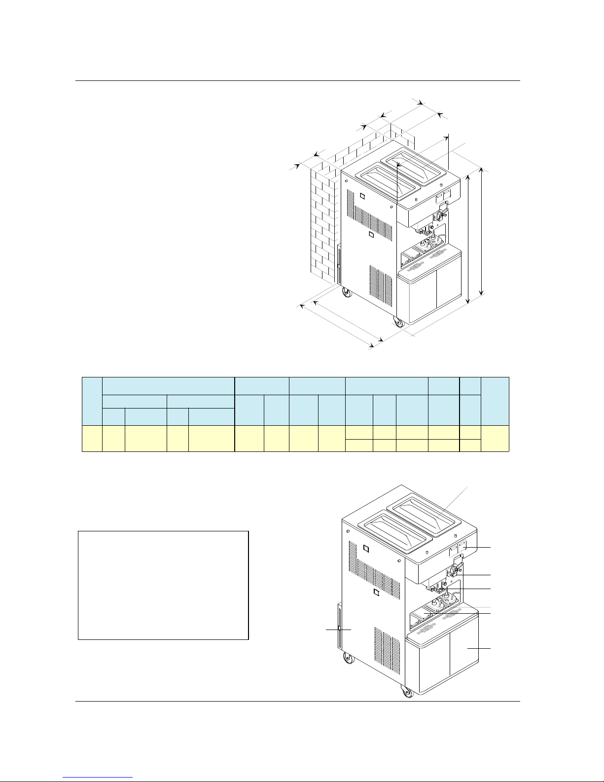
MACHINE ASSEMBLY IDENTIFICATION
LEGEND:
1 Syrup tanks cabinet
2 Hopper cover
3 Hot toppings
4 Room temperature toppings
5 Dispensing head shake side
6 Dispensing head soft side
7 Air condenser
7
1
4
3
6
1
2
5
4
0
i
n
4
1
i
n
2
8
i
n
58 in
60 in
2
i
n
4
i
n
2
i
n
Page 11
Carpigiani K 3 User’s guide
This manual is for the exclusive use of licensees and employees of McDonald’s Systems Inc Page 11 of 63
Version 5: October 2012
1.2.6 AUTOMATIC PASTEURISATION CYCLE
The machine has been pre-set in the factory to start automatically the pasteurisation cycle every night at 2
am. (the automatic pasteurisation time can be re-set at a different time by a trained technician.
1.2.7 TEMPERATURE CONTROL
When the machine is set to STOP, the tank temperature is controlled: if it is higher or equal to 59 °F (1 5°C),
the execution of the pasteurisation program is forced. So, by pressing the PROD. button, the
pasteurisation program will automatically start.
NOTE:
After the machine’s brush cleaning, it is necessary to press the PROD. button within 60 minutes after the
front lid closing. During this 60 minutes the test at 59°F (15°C) is masked and Production is accepted. After
60 minutes, the machine does not accept the PROD. button any more and it sets to pasteurisation
function.
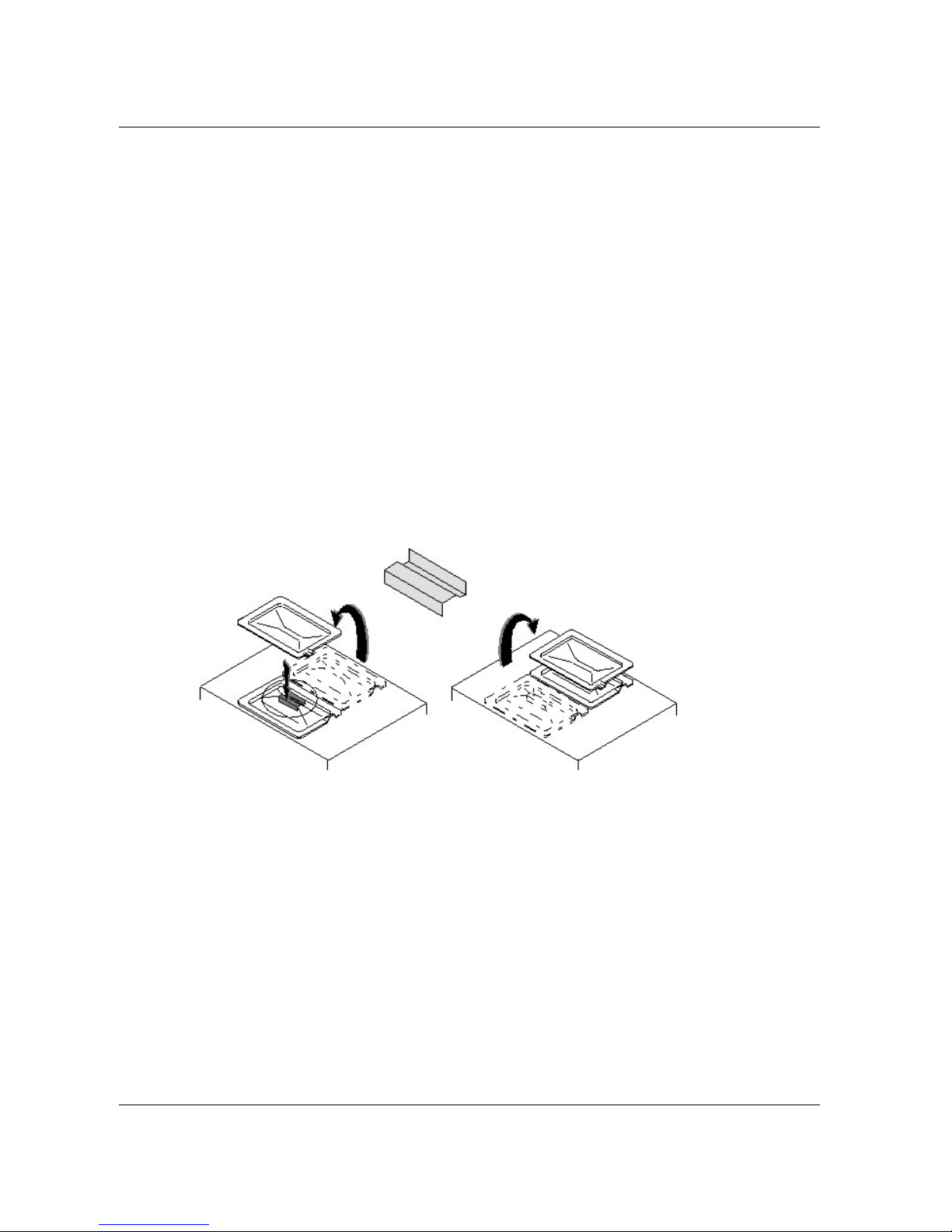
1.2.8 TANK LIDS HOLDER
When you need to refill the mix tank, lift the lid and turn it upside down. Insert the handle of the lid in the
slot of the holder placed on the other lid. You need not to remove the holder.
LID HOLDER
Page 12
Carpigiani K 3 User’s guide
This manual is for the exclusive use of licensees and employees of McDonald’s Systems Inc Page 12 of 63
Version 5: October 2012
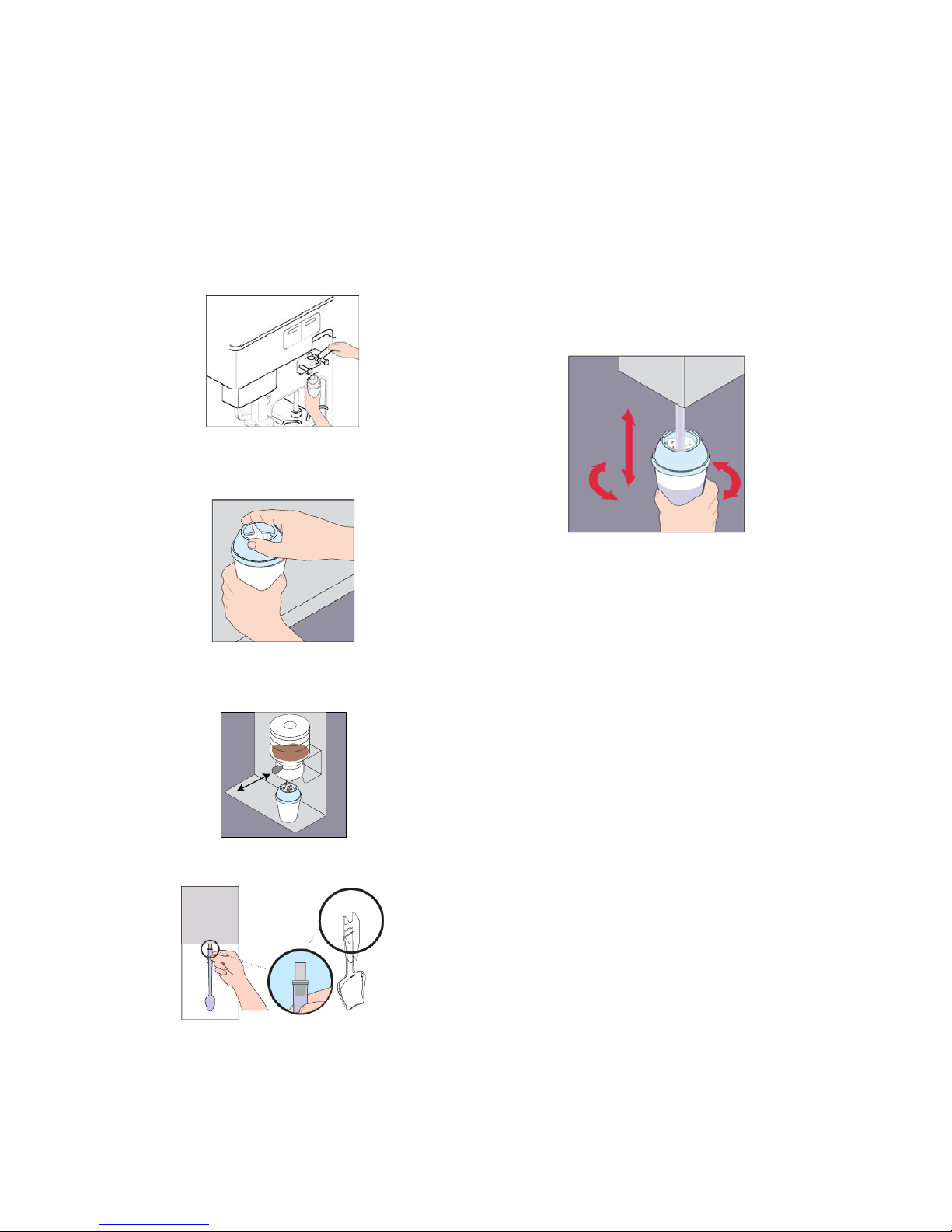
1.2.9 MIXER (OPTIONAL)
Operating procedure
1. Hold a cup under soft-serve dispensing nozzle.
2. Pull draw lever completely forward and fill up
the cup.
3. Place a dome lid on top of the cup.
Tip: Set the cup on a level surface.
4. Hold the cup under the requested inclusion
dispenser. Slide the mix-in dispenser’s handle,
to dispense the product
5. Snap mixing spoon onto blender connector (be
careful not to touch spoon)
6. Push the cup onto the blender mixing spoon,
hold the cup with one hand and push the
switch on with the other hand. Using one hand,
blend the cup for 7 seconds. While blending,
move the cup from side to side and up and
down.
7. Once blender stop rorating, hold the cup in
one hand and release the mixing spoon from
the blender with the other hand.
8. Serve the cup.
Page 13
Carpigiani K 3 User’s guide
This manual is for the exclusive use of licensees and employees of McDonald’s Systems Inc Page 13 of 63
Version 5: October 2012
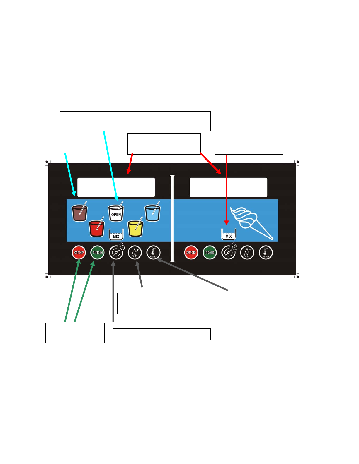
Warning light for LOW
mix level (reserve)
LCD back lights flashing for
warning :
“read info on display”
WHITE BASE DISPENSING BUTTON (for SMOOTHY)
- OPEN PISTON TO EMPTY THE MACHINE (CLEANING)
MILK SHAKE
DISPENSING BUTTONS
2. INSTRUCTIONS FOR USE
2.1 CONTROLS
The K 3 is equipped with two front push-button panels, one for the con trols related to the SHAKE side and
one for the controls related to the SUNDAE side.
IMPORTANT
Push-buttons are activated keeping the finger (not the nail) pressed on it for at least 1/2 second
(safety feature).
WARNING
TO REDUCE WEARING OF THE BEATER BLADE (POS. 430) USE AGITATION FUNCTION JUST FOR
THE TIME STRICTLY NECESSARY.
Storage Led
lights on from Past. End
“-” decrease button for manager menu
Alarm and warning restore
Pasteurisation Led
lights on from start Past. till Past. End
“+” increase button for manager menu
Agitation Button/Lock button
MAIN FUNCTIONS:
- Stop
- Production
Page 14
Carpigiani K 3 User’s guide
This manual is for the exclusive use of licensees and employees of McDonald’s Systems Inc Page 14 of 63
Version 5: October 2012
2.1.1 MILK SHAKE FUNCTIONS
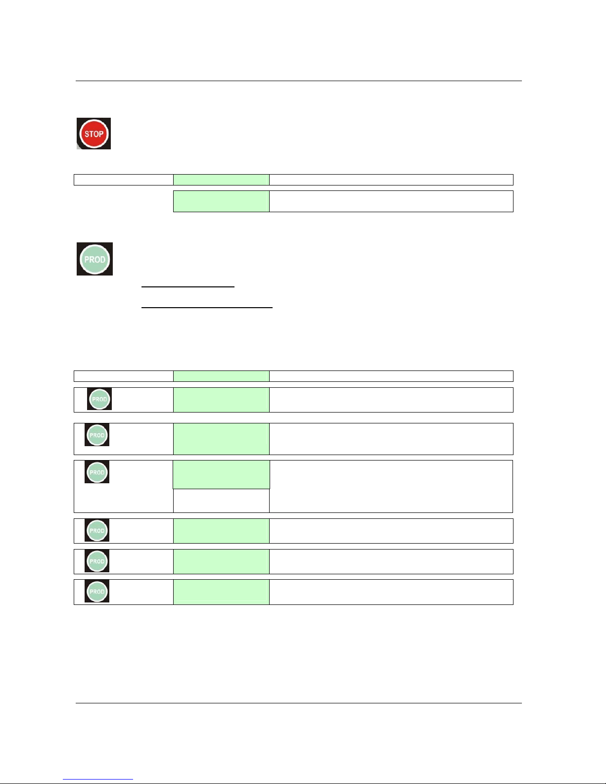
STOP BUTTON
By pressing this button during operation, the machine stops (LED on).
DISPLAY Comments
16:29:27 Tue
When the machine is in STOP, the display shows Time
and Date.
PRODUCTION BUTTON
Preparation (startup):
On pushing this button, its LED will blink for 15 minutes while the
machine is freezing the product. For that time, dispensing is not allowed.
Production (LED is always on):
The product is ready to be dispensed and it is kept at the
desired consistency by the Hard-o-Tronic system. If the machine has been in the production
mode and then placed in Stop, the 15 minutes start up procedure will be automatically bypassed
if the time in Stop does not exceed 60 minutes; otherwise the start up procedure will be repeated.
By pressing this button when in STOP, the display indicates:
KEY
DISPLAY comments
1
Do Not Serve !
TEV +19°C W-14
When the Milk Shake is not ready, the display shows: “DO
NOT SERVE“
2
Hopper +14°C
Cylinder +13°C
In this box the display shows the Hopper’s temperature in
the first line (above) and the Cylinder’s temperature in the
second one.
3
In this box the display shows in the first line (above):
Set=065: the shake consistency to be reached
Hot=035: the shake consistency actually detected in the
cylinder
Liv=00000 for technician
4
Cones today
12345
In this box the display shows the daily quantity of cones
(starting from 0:00 until 23:59).
5
Total Cones
0923456780
In this box the display shows the total quantity of cones
6
TEV+010 TGV-022
TEC+013 TE1-012
In this box the display shows various probes of the SHAKE
part ( no °C nor °F are displayed).
Pushing PROD again, we return to first display (1).
Set=065 Hot=035
Lev=00000
Page 15
Carpigiani K 3 User’s guide
This manual is for the exclusive use of licensees and employees of McDonald’s Systems Inc Page 15 of 63
Version 5: October 2012
Machines equipped with “LONWORKS” device, Service Pin:
Activation of the service pin, proceed as follows:
1. Place one side of the machine in STOP
2. Press PROD
button for 10 seconds (a beep signal is activated)
At the end of the procedure put the side in standard function (Production or Storage)
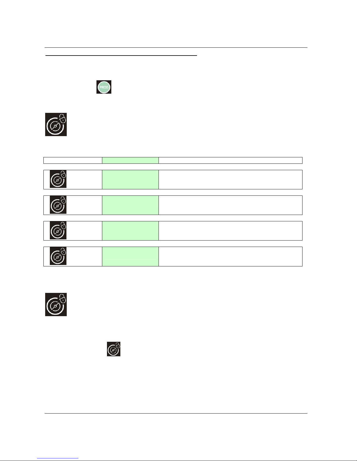
AGITATION BUTTON (CLEANING)
By pressing this button from STOP, the led turns on and the display indicates:
KEY DISPLAY Comments
1
HOT=058 TEC+014
Beater + Pump ON
Pressing this button one time, the beater motor and the
mix pump motor will turn ON. HOT (consistency) and TEC
(cylinder’s temperature) are displayed in the first line.
2
HOT=058 TEC+014
Pump ON
Pressing this button for the second time we arrest the
beater motor but the mix pump remains on.
3
HOT=058 TEC+014
Beater ON
Pressing this button for the third time we activate the
beater motor and the mix pump motor stops.
4
HOT=058 TEC+014
Beater + Heating
Pressing this button for the fourth time we activate both the
beater motor and the mix pump motor and the heating as
well to help the product to melt.
Pressing Production again we return to first display.
LOCK BUTTON
To clean the keyboard panel with a clean towel it is recommended to block the keys of the
keyboard as follows:
Keep the
button pressed for 3 seconds, the respective led will flash indicating that
the keyboard is locked. At this point you can clean the keyboard safely. To restart it, just
keep the same key pressed for 3 seconds and the led will turn off.
Page 16
Carpigiani K 3 User’s guide
This manual is for the exclusive use of licensees and employees of McDonald’s Systems Inc Page 16 of 63
Version 5: October 2012
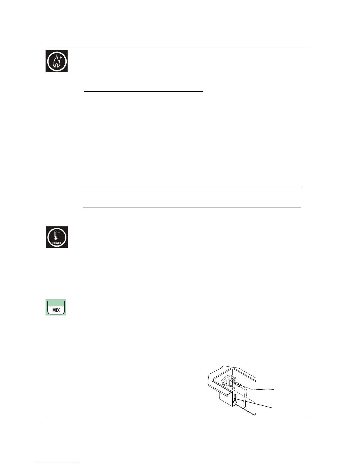
PASTEURISATION FUNCTION / INCREASE FUNCTION
The pasteurisation function can be activated only if the mix in the hopper is abo ve
the Medium Level (“ADD MIX” message on display must be off).
AUTOMATIC PASTEURISATION CYCLE:
while the machine is in production
(pasteurisation LED on) and the mix is above the medium level, the heat-treatment cycle
starts automatically at a certain time (as programmed in the Manager M enu normally at
2:00 AM).
During the display indicates “HEAT-TREATMENT CYCLE” the mix in the hopper and in the
cylinder is heated up to 65°C, kept at 65°C for 30 minutes and finally cooled down to 2°C.
At the end of the cycle, the display shows “PASTO END” followed by date and hour of
termination. The machine passes automatically to STORAGE function.
To serve shake, press STOP, then the PROD button, but only if the machine hasn’t passed
automatically in PRODUCTION yet.
Note: Once the pasteurisation cycle has started, it can not be interrupted. The
complete pasteurisation cycle will take less than 4 hours to be completed.
During the pasteurisation and Pause cycles, the mix in the machine is very hot. Do
not attempt to recover the mix nor to disassemble the machine.
WARNING
Do not dispense sundae nor dismount the machine during the pasteurisation
because the product is very hot and under pressure.
STORAGE / DECREASE FUNCTION / RESET ALARM MESSAGES
The Storage Led lights ON as soon as the Pasteurisation cycle ends. The machine
preserves the mix at +2°C (35°F) in the hoppe r and in t he cylinder.
- this button is also used to decrease the value in the Manager menu
- this button is also used to RESET the ALARM MESSAGES on the display.
MIX LEVEL SIGNAL
In each hopper we have 2 level sensors: MEDIUM level and LOW level.
- When the MIX LEVEL LED flashes, it means that the mix level in the hopper is lower
than the medium mix level sensor.
- When the MIX LEVEL LED is on, it means that the mix level in the hopper is lower
than the minimum mix level sensor.
The display indicates ADD MIX or MIX OUT.
Mix level
sensor
Maximum filling
level indicator
Page 17
Carpigiani K 3 User’s guide
This manual is for the exclusive use of licensees and employees of McDonald’s Systems Inc Page 17 of 63
Version 5: October 2012
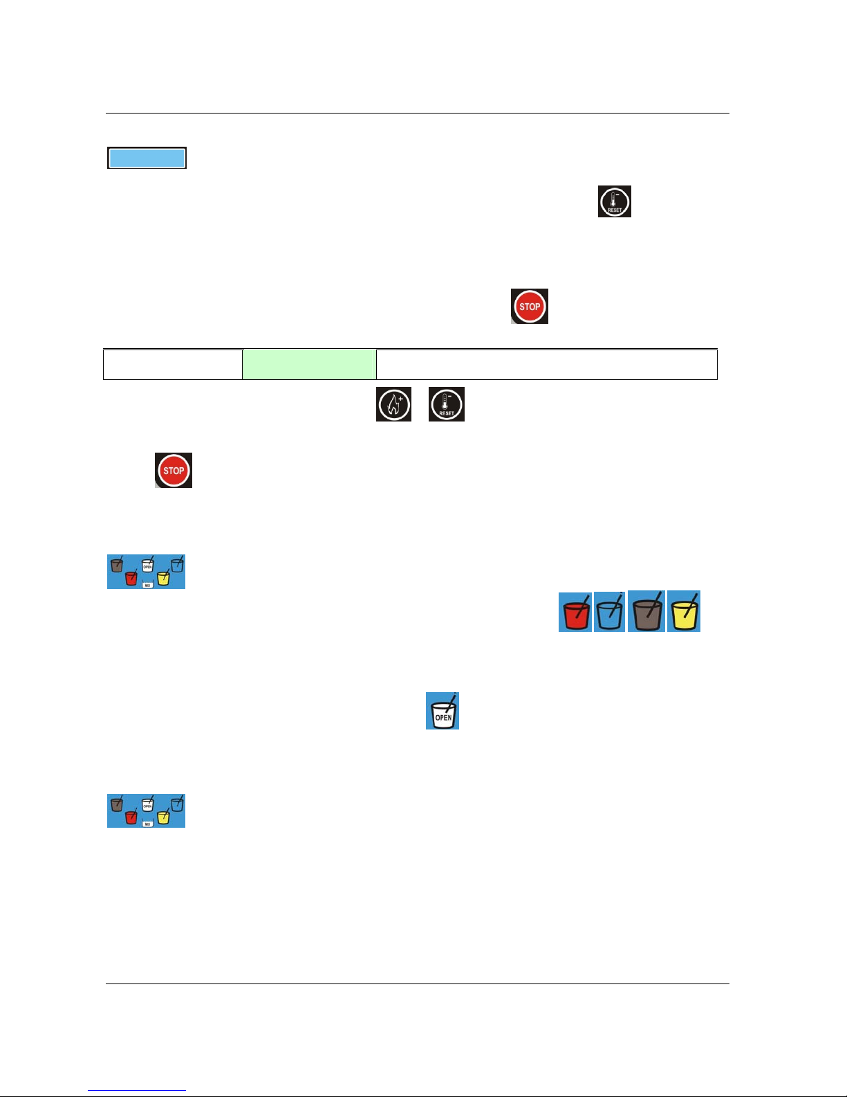
When the LCD back light is blinking, that means an alarm has tripped.
When it becomes still, the alarm which has previously tripped, has automatically reset and
the indication on the display must be reset by pressing RESET button
.
EVENTS
In order to read the events, the machine must be in STOP, so keep the pressed until ****READ
EVENTS**** is displayed.
02:00:00 06 APR
START PASTEUR
The first event will appear on the display. Push or in order to scroll UP or DOWN the events
list.
PUSH TO EXIT THE EVENTS READING AND GO TO STOP.
MILK SHAKE DISPENSING BUTTONS
Every “coloured cup” button corresponds to a milk shake flavour.
In PRODUCTION, the product is dispe nsed acc ord in g to the flav our selec t ed .
If, while dispensing milk shake, you push any “coloured cup” button, the milk shake will
immediately stop without reaching its automatic level; this function may be used to
dispense small portions. (tasting function).
When in STOP, by pushing th e button
the piston opens and remains opened; by
pushing again it closes.
When in STOP, the “coloured cup” button are used for calibration of syrup quantity.
SYRUP QUANTITY CHECK AND SYRUP SYSTEM CLEANING
While the machine is in STOP:
- Push one time only the “coloured cup” button.
- Syrup will be dispensed for 5/7 seconds.
- Check the quantity of the syrup using the calibration cup.
- If the quantity of syrup is not satisfactory then modify the calibration as explained in
the manager menu.
- By pushing a second time while the syrup pump is ON, the pump will run at MAX
speed in order to flush and clean the syrup tubes.
Page 18
Carpigiani K 3 User’s guide
This manual is for the exclusive use of licensees and employees of McDonald’s Systems Inc Page 18 of 63
Version 5: October 2012
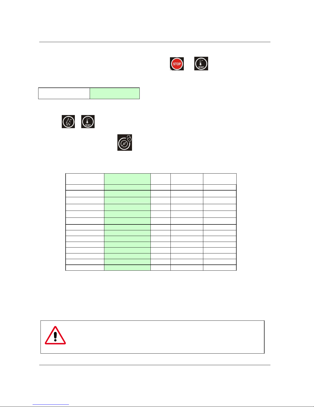
MANAGER MENU
1) To access the Manager Menu press simultaneously both and keys, then release them
immediately.
On the display you will read the first step of the Manager Menu:
Time
Step U01 10
The first row indicates the step number, and the second row indicates the description and value.
2) Push
or in order to increase or decrease the value.
3) Push STOP to move to the next step.
4) To exit the Manager Menu push
button.
The following table illustrates all steps of the Manager Menu:
STEP N°
(first row)
Display
(second row)
Min Max
Default
U01 Hours 00 23
U02 Minutes 00 59
U03 Day of Week SUN SAT
U04 Day of Month 01 31
U05 Month Jan Dec
U06 Year 2000 2099
U07 Language ITA DEU
ENG
U08 Start Prod. Hour 00
23+no+auto
08
U09 Start Past .Hour 00 23+no
02
U10 Beeper Lev. Enabled No Yes+Man
Yes
U11 Syrup 1 pump speed 010 240
150
U12 Syrup 2 pump speed 010 240
120
U13 Syrup 3 pump speed 010 240
100
U14 Syrup 4 pump speed 010 240
090
U01 -> 06 Time and date settings
U07 Language selection.
U08 Start Production time.
U09 Start Pasteurisation time.
U10 Disables/ enables the sound alarm when mix level is low..
U11 -> 14 Syrup pumps speed to calibrate the syrup quantity (1 oz fluid ounce in 5 or 7 sec)
THE MACHINE IS READY FOR START-UP ONLY AFTER IT HAS BEEN PERFECTLY
CLEANED AND SANITIZED.
FOR HYGIENIC AND SAFETY REASONS, HANDS SHOULD
NEVER BE PLACED INSIDE THE MIX HOPPER WHILE THE MACHINE IS WORKING.
Page 19
Carpigiani K 3 User’s guide
This manual is for the exclusive use of licensees and employees of McDonald’s Systems Inc Page 19 of 63
Version 5: October 2012
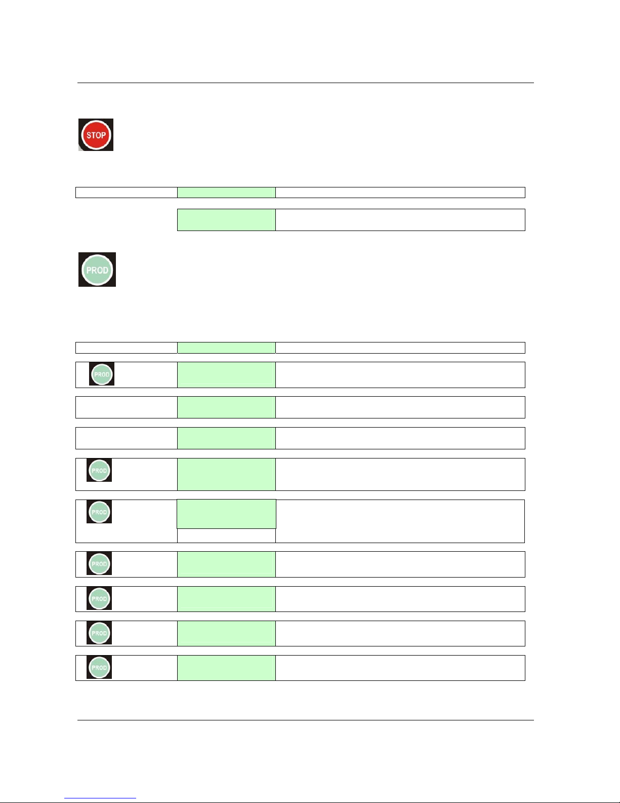
2.1.2 SUNDAE FUNCTIONS
STOP BUTTON
By pressing this push-button during operation, the machine stops (LED on).
DISPLAY Comments
10:33:21 Fri
When the machine is in STOP, the display shows Time and Date.
PRODUCTION BUTTON
Press PROD button to start the production mode (LED on). The motor and compressor are
automatically controlled by HARD-O-TRONIC system.
By pressing this button from STOP, the display indicates:
KEY DISPLAY comments
1
Do Not Serve!
TEV +19°C W -14
When the sundae is not ready, the display shows: “DO
NOT SERVE“
Sundae Ready!
TEV +19°C W -14
When the sundae has reached the desired consistency the
display shows “SUNDAE READY”.
Do Not Serve!
Beater HT Sensor
In case of ALARM, this will be displayed in the second row
2
Hopper +14°C
Cylinder +13°C
In this box the display shows the Hopper’s temperature in
the first line (above) and the Cylinder’s temperature in the
second one.
3
In this box the display shows in the first line (above):
Set=100: set HOT SOFT
HOT=085: the consistency actually detected in the soft
cylinder.
4
Cones today
12345
In this box the display shows the daily quantity of cones
(starting from 0:00 until 23:59).
5
Total Cones
0923456780
In this box the display shows the total quantity of cones.
6
TEV+010 TGV-022
TEC+013 TE1-012
In this box the display shows various probes of the SHAKE
part ( no °C nor °F are displayed).
7
Topping +057
Set Topping +055
In this box the display shows the Topping probe ( no °C
nor °F are displayed), with the respective temperature sets.
Pushing PROD again, we return to the initial display.
Set=100 Hot=085
Page 20
Carpigiani K 3 User’s guide
This manual is for the exclusive use of licensees and employees of McDonald’s Systems Inc Page 20 of 63
Version 5: October 2012
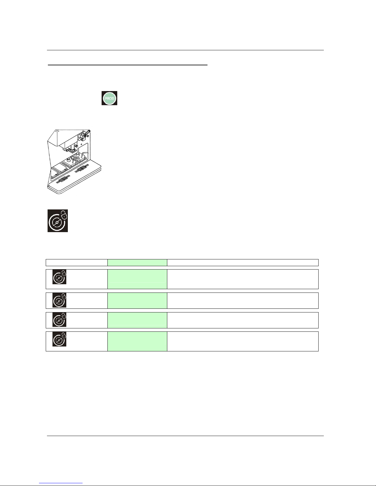
Machines equipped with “LONWORKS” device, Service Pin:
Activation of the service pin, proceed as follows:
1. Place one side of the machine in STOP
2. Press PROD
button for 10 seconds (a beep signal is activated)
At the end of the procedure put the side in standard function (Production or Storage)
TOPPING HEATER
In PROD. function the two hot topping containers are heated automatically to
reach the desired temperature. In case the water level in the bain-marie is too low
the display will indicate an alarm in order to refill it with water.
AGITATION BUTTON (CLEANING)
By pressing this button from STOP, the led turns on. The beater and the mix pump motor
get ON until you press STOP or after 3 minutes. The display indicates:
KEY
DISPLAY comments
1
HOT=058 TEC+014
Beater + Pump ON
Pressin
g
this button one ti m e, the beater motor and the
mix pump motor will turn ON. HOT (consistency) and TEC
(cylinder’s temperature) are displayed in the first line.
2
HOT=058 TEC+014
Pump ON
Pressin
g
this button for the second time we arrest the
beater motor but the mix pump remains on.
3
HOT=058 TEC+014
Beater ON
Pressin
g
this button for the th i r d tim e w e activate the
beater motor and the mix pump motor stops.
4
HOT=058 TEC+014
Beater + Heating
Pressing this button for the fourth time we activate both
the beater motor and the mix pump motor and the h eat ing
as well to help the product to melt.
Pressing Cleaning again we return to the initial display.
Page 21
Carpigiani K 3 User’s guide
This manual is for the exclusive use of licensees and employees of McDonald’s Systems Inc Page 21 of 63
Version 5: October 2012
LOCK BUTTON
To clean the keyboard panel with a clean towel it is recommended to block the keys of the
keyboard as follows:
Keep the
button pressed for 3 seconds, the respective led will flash indicating that
the keyboard is locked. At this point you can clean the keyboard safely. To restart it, just
keep the same key pressed for 3 seconds and the led will turn off.
PASTEURISATION FUNCTION / INCREASE FUNCTION
The pasteurisation function can be activated only if the mix in the hopper is abo ve
the Medium Level (“ADD MIX” message on display must be off).
AUTOMATIC PASTERUSATION CYCLE:
while the machine is in production
(PASTEURISATION LED on) and the mix is above the medium level, the pasteu risation
cycle starts automatically at a certain time (as programmed in the Manager Menu normally
at 2:00 AM).
During the display indicates “HEAT-TREATMENT CYCLE” the mix in the hopper and in the
cylinder is heated up to 65°C, kept at 65°C for 30 minutes and finally cooled down to 2°C.
At the end of the cycle, the display shows “PAST. END” followed by date and hour of its
termination. The machine passes automatically to STORAGE function.
To serve shake, press STOP, then the PROD button, but only if the machine hasn’t passed
automatically in PRODUCTION yet.
Note: Once the pasteurisation cycle has started, it can not be interrupted. The
complete heat-treatment cycle will take less than 4 hours to be completed.
During the pasteurisation and Pause cycles, the mix in the machine is very hot. Do
not attempt to recover the mix nor to disassemble the machine.
WARNING
Do not dispense sundae nor dismount the machine during the pasteurisation
because the product is very hot and under pressure.
STORAGE / DECREASE FUNCTION / RESET ALARM MESSAGES
The Storage Led lights ON as soon as the Pasteurisation cycle ends. The machine
preserves the mix at +2°C (35°F) in the hoppe r and in t he cylinder.
- this button is also used to decrease the value in the Manager menu
- this button is also used to RESET the ALARM MESSAGES on the display.
MIX LEVEL SIGNAL
In each hopper we have 2 level sensors: MEDIUM level and LOW level.
- When the MIX LEVEL LED flashes, it means
that the mix level in the hopper is lower than
the medium mix level sensor.
- When the MIX LEVEL LED is on, it means that
the mix level in the hopper is lower than the
minimum mix level sensor.
The display indicates ADD MIX or MIX OUT
Mix level
sensor
Maximum
filling level
in
dicato
r
Page 22
Carpigiani K 3 User’s guide
This manual is for the exclusive use of licensees and employees of McDonald’s Systems Inc Page 22 of 63
Version 5: October 2012
When the LCD back light is blinking, that means an alarm has tripped.
When it becomes still, the alarm which has previously tripped, has automatically reset and
the indication on the display must be reset by pressing the RESET
button.
EVENTS
In order to read the events, the machine must be in STOP, so keep the
pressed until ****READ
EVENTS**** is displayed.
02:00:00 06 APR
START PASTEUR
The first event will appear on the display. Press or in order to scroll UP or DOWN the events
list.
Press
to exit the events reading and go to STOP.
MANAGER MENU
1) To access the Manager Menu press simultaneously both and keys, then release
them immediately.
On the display you will read the first step of the Manager Menu:
Step
Hour U01 10
The first row indicates the step number, and the second row indicates the description and value.
2) Press
or in order to increase or decrease the value.
3) Press STOP to move to the next step.
4) To exit the Manager Menu press the
key.
Page 23
Carpigiani K 3 User’s guide
This manual is for the exclusive use of licensees and employees of McDonald’s Systems Inc Page 23 of 63
Version 5: October 2012
The following table illustrates all steps of the manager menu:
Step
(first row)
Display ENG
(second row)
Min Max
Default
U01 Hours 00 23
U02 Minutes 00 59
U03 Day of Week Sun Sat
U04 Day of Month 01 31
U05 Month Jan Dec
U06 Year 2000 2099
U07 Language Eng DEU
ENG
U08 Start Prod. Time 00
23+no+auto
08
U09 Start Past. Time 00 23+no
02
U10 Lev. Beep Enable No Yes
Yes
U11 Speed Pump 1 No No
No
U01 -> 06 Time and date settings
U07 Language selection.
U08 Start Production time.
U09 Start Pasteurisation time.
U10 Disables/enables the sound alarm when mix level is low.
U11 Unused
THE MACHINE IS READY FOR START-UP ONLY AFTER IT HAS BEEN PERFECTLY
CLEANED AND SANITIZED.
FOR HYGIENIC AND SAFETY REASONS, HANDS SHOULD
NEVER BE PLACED INSIDE THE MIX HOPPER WHILE THE MACHINE IS WORKING
Page 24
Carpigiani K 3 User’s guide
This manual is for the exclusive use of licensees and employees of McDonald’s Systems Inc Page 24 of 63
Version 5: October 2012
2.2 OPERATIONS
2.2.1 DISPENSING MILK SHAKE
Once the milk shake has completed the freezing cycle and the LED is on solid, place a cup on the cup
holder and press one of the “coloured cup” buttons (brown, red, yellow or blue) in order to dispense milk
shake.
The machine automatically dispen ses the milk shake in the cup, placed on the cup holder, up to the
level set by the sensor.
The dispensing may be stopped at anytime b y pressing any of the “coloured cup” buttons.
WARNING
It is important to keep the sensor clean and to use a fresh clean
cup of the recommended type.
The vertical joint of the cup (with double pasteboard layer)
must be always placed away from the sensor.
2.2.2 DISPENSING SUNDAE
In order to dispense sundae, place a cup or a cone under the spout and
slowly pull down the dispensing handle. As soon as the sundae comes out,
twist the cup or the cone to form a cone-shaped serving.
When the portion has reached the desired size, close the dispensing handle and
quickly pull the cone or the cup down in order to sharpen the tip.
2.3 PROGRAMMED CLEANING CYCLE
The machine is equipped with an automatic system that calls for washing of the parts in contact with the
product at least every 14 days.
In PROD. the second row of the display indicates the days remaining to the next cleaning..
Sundae Ready!
TEV +19°C W -14 --> Indicates cleaning within 14 days.
Page 25

Carpigiani K 3 User’s guide
This manual is for the exclusive use of licensees and employees of McDonald’s Systems Inc Page 25 of 63
Version 5: October 2012
2.4 POWER BLACK- OUT
In the event of a black-out with the machine in:
AGITATION
PASTEURISATION (HEATING or PAUSE stage)
the machine will resume operating in the same function where it was when the power went off.
If the machine was in one of the following functions:
STORAGE
PRODUCTION
PASTEURISATION (COOLING stage)
Upon the return of power, the temperature at the time of failure and the duration of the black-out will be
automatically checked and the machine will resume operating in the same function or it will start a new
PASTEURISATION cycle, in accordance with the applicable safety standards.
CAUTION
If the blackout exceeds four hours, in order to avoid health hazards
in the dispensed product, it is necessary to disassemble, wash, rinse and
sanitize the parts, as indicated in Section 4 of this manual.
Page 26
Carpigiani K 3 User’s guide
This manual is for the exclusive use of licensees and employees of McDonald’s Systems Inc Page 26 of 63
Version 5: October 2012
3. DAILY CLOSING PROCEDURES
NOTE:
The machine is equipped with an automatic system wich calls for washing of the parts in contact with the
product every 14 days. This system disables the dispensing function at the end of the fourteenth day (see
cap. 6)
3.1 SHAKE SIDE
Make sure your hands are clean and sanitized before performing the following procedures.
3.1.1 DISASSEMBLING AND CLEANING THE COMPONENTS:
Remove cup holder, drip tray, drip troughs and hopper covers to wash, rinse, sanitize them at the sink and
replace them on the machine. Before replacing the tank covers, clean the upper area inside the tanks with
a sanitised cloth.
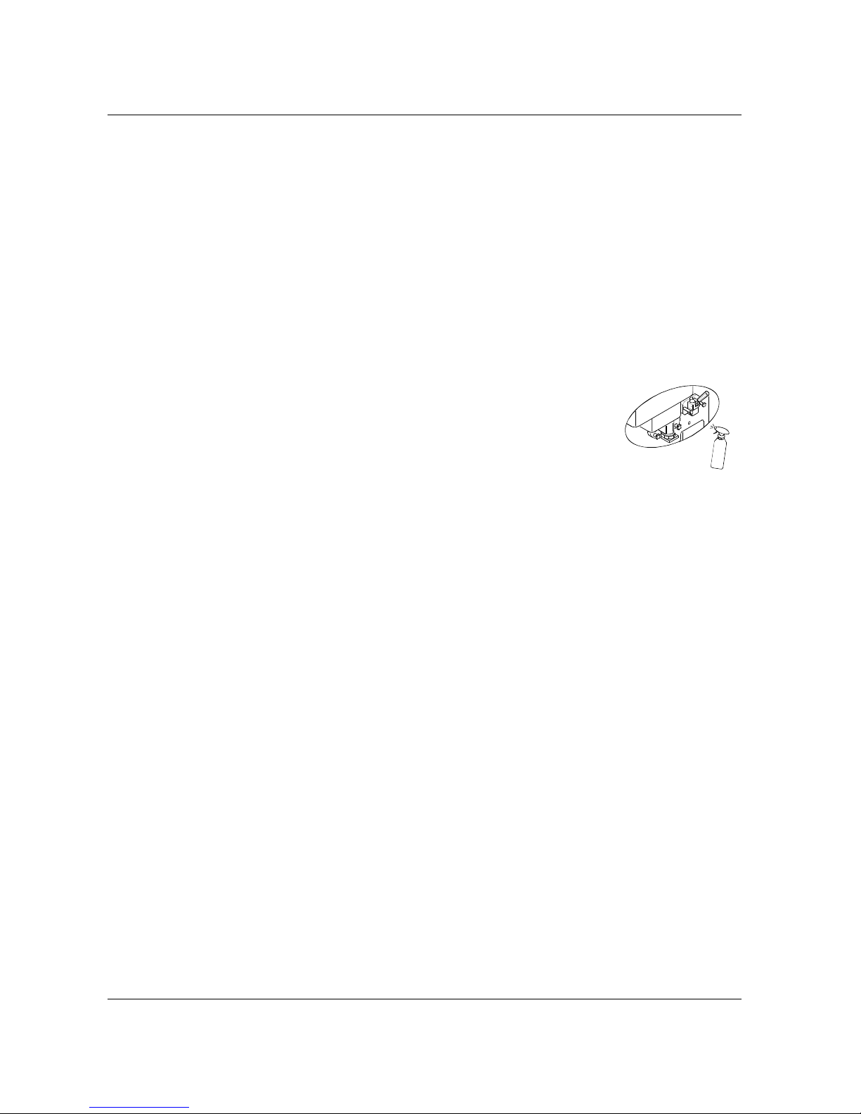
3.1.2 SANITIZING THE DOOR AREA:
a) Fill an empty pail with McD Sanitizer prepared in water at 70-90°F (21-32°C) (1 packet
in 2-1/2 gallons (9-1/2 litres) of water = 100 PPM ) and mix the powder.
b) Return to the machine with some McD sanitizing solution in the container.
c) Immerse the brushes in the sanitising solution and wipe several times the dispensing
area of the door, the small cover underneath the door, the dispensing hole, the area
above the same door and everywhere inside the door.
d) Spray the sanitising solution on the dispensing part, on the door area, underneath the piston cover and all
around the door.
e) Using a clean, sanitized towel, wipe the freezer door, the front panel area around the freezer door and all
other surrounding areas.
3.1.3
SYRUP LINE CLEANING / SANITIZING
Syrup suction tubes/ connectors cleaning :
a) Remove the syrup tubes from their jugs or disconnect the syrup connectors from the bags,
b) Clean the outer surface of the syrup tubes/connectors with a clean, sanitized towel.
c) Remove the syrup jugs/syrup bags from the syrup compartment.
Sanitizing the syrup lines:
a) Fill an empty pail with McD sanitizer prepare d in water at 122-140°F (50-6 0°C) (1 pack et in 2-1/2 gallons (9-
1/2 litres) of water = 100 PPM) and mix the powder.
b) Place the syrup tubes’ connectors in the sanitizing solution. Press the STOP button, then the corresponding
“coloured cup” button twice to run the syrup pump at maxim um speed and let the s anitizing solution flow for
1 minute. Press the STOP button to stop the syrup pump.
c) Leave the sanitizing solution in the syrup line for 10 minutes.
d) Repeat for all syrup lines.
Removing the sanitizing solution from syrup lines
a) Remove the connectors from the pail containing the sanitizing so lution and put th em on a cl ean to wel.
b) Press the corresponding “coloured cup” button twice to run the syrup pumps at maximum speed in order to
empty the tube from the remaining sanitizing solution
c) Press STOP button to stop the syrup pump
d) Repeat for all syrup lines
Loading the syrup lines with syrup
a) Connect the syrup tubes to their jugs or connect the syrup connectors to the syrup bags.
b) Place empty bucket under the spout.
c) Press the “coloured cup” button twice until the syrup is dispensed and discard it.
d) Press STOP button to stop the syrup pump.
e) Repeat for all syrup lines.
f) Using a clean, sanitized towel, wipe the door compartment.
NOTE
:
It’s possible to be displayed the message “why in stop". This message reminds you to return the machine
in production mode at the end of the syrup lines cleaning.
S
A
N
I
T
I
Z
E
R
Page 27
Carpigiani K 3 User’s guide
This manual is for the exclusive use of licensees and employees of McDonald’s Systems Inc Page 27 of 63
Version 5: October 2012
.
3.1.4 PREPARING THE MACHINE FOR THE OVERNIGHT HEAT TREATMENT CYCLE.
a) Open the hopper cover to verify the mix level.
b) Fill the hopper with McD shake mix to the Max level. The “ADD MIX” message on the display must be off.
c) Keep the machine in PROD mode.
WARNING
If the mix in the hopper is below the medium level ("ADD MIX" MESSAGE ON DISPLAY), the pasteurisation cycle
will not start.
The heat treatment cycle is automatic and starts during the night (set time).
Both sides of the machine should be in production mode to perform properly the heat-treatment cycle.
3.1.5 FRONT PANEL CLEANING
To clean the keyboard panel with a clean sanitized towel is recommended to lock the keys as follows:
Press
for 3 seconds, light will flash indicating that the front panel is now locked. Clean the front panel
and the keybord panel with a clean sanitized towel.
After cleaning press
for 3 seconds, to unlock the keyboard.
Page 28
Carpigiani K 3 User’s guide
This manual is for the exclusive use of licensees and employees of McDonald’s Systems Inc Page 28 of 63
Version 5: October 2012
3.2 SUNDAE SIDE
Make sure your hands are clean and sanitized before performing the following procedures.
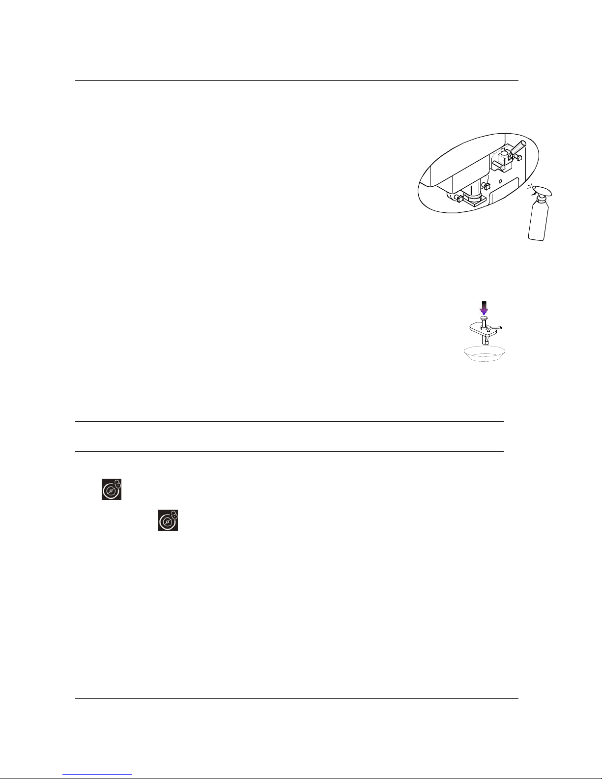
3.2.1. SANITIZING THE DOOR AREA SURFACE:
a) Fill an empty pail with McD Sanitizer prepared in water at 70-90°F (21-
32°C) (1 packet in 2-1/2 gallons (9-1/2 litres) of water = 100 PPM) and mix
the powder.
b) Return to the machine with a small amount of McD sanitizing solution
c) Imm erse the brushes in the sanitising solution and wipe several times the
dispenser of the door, the same door, the area of the le ver and all around
the door, including the holes of the knobs.
d) Spray the sanitising solution on the dispenser of the door, on the
surrounding area and on the same door.
e) Clean the front of the machine wit h a clea n an d s an itiz ed towel.
3.2.2 TOPPING PUMPS CLEANING:
a) Remove the topping covers and pumps. Protect the exposed topping containers with a cover, in
order to avoid the product’s exposure to the air.
b) Wash the covers and the external part of the motor carefully using water and detergent.
c) Fill the container with water at 50-60°C (122-140°F), place the pumps inside, press the
distribution pistons and rinse them until the outflowing water is clean.
d) Fill the container with the sanitizing solution, place the pumps inside and push the
distribution pistons to sanitiz e t hem ( hol d on for 1 minute).
e) Place the covers and pumps on the clean , dry surface and leave them drying in the air
overnight.
3.2.3
PREPARING THE MACHINE FOR THE OVERNIGHT PASTEURISATION CYCLE.
a) Open the hopper cover to check the mix level.
b) Fill the hopper with McD shake mix to the Max level. T he “ADD MIX” message on the display must be off.
c) Keep the machine in PROD mode.
WARNING
If the mix in the hopper is below the medium level ("ADD MIX" MESSAGE ON DISPLAY),
the pasteurisation cycle will not start.
3.2.4 FRONT PANEL CLEANING
To clean the keyboard panel with a clean sanitized towel is recommended to lock the keys as follows:
Press
for 3 seconds, light will flash indicating that the front panel is now locked. Clean the front panel
and the keybord panel with a clean sanitized towel.
After cleaning press
for 3 seconds, to unlock the keyboard.
S
A
N
I
T
I
Z
E
R
Page 29
Carpigiani K 3 User’s guide
This manual is for the exclusive use of licensees and employees of McDonald’s Systems Inc Page 29 of 63
Version 5: October 2012
4. DAILY OPENING PROCEDURES
Check that pasteurisation cycle has been successfully completed and the display indicates th e message "PAST. END",
followed by the time and day of its comp letio n.
If the pasteurisation cycle wasn’t completed successfully ,the machine will be locked out. Check the reason
reading the alarm messages and press
in order to reset the message on the display. Press ST OP then
PROD. button to run pasteurisation cycle manually. Once the pasteurisation cycle is completed successfully, the
lock out resets automatically and the machine is ready to go in production. No product can be dispensed during
the past eurisation cy cle (ap p roximately three hours).
4.1 MILK SHAKE SIDE
Make sure your hands are clean and sanitized before performing the following procedures.
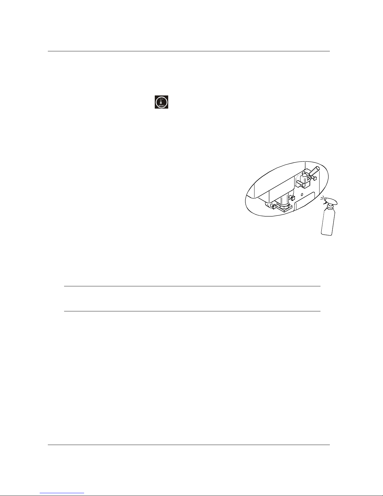
4.1.1 SANITIZING THE DOOR AREA:
a) Fill an empty pail with McD Sanitizer prepared in water at 70-90°F
(21-32°C) (1 packet in 2-1/2 gallons (9-1/2 litres) of water = 100
PPM) and mix the powder.
b) Immerse the brushes in the sanitising solution and wipe several
times the dispensing area of the door, the small cover underneath
the door, the dispensing hole, the area above the same door and
everywhere inside the door.
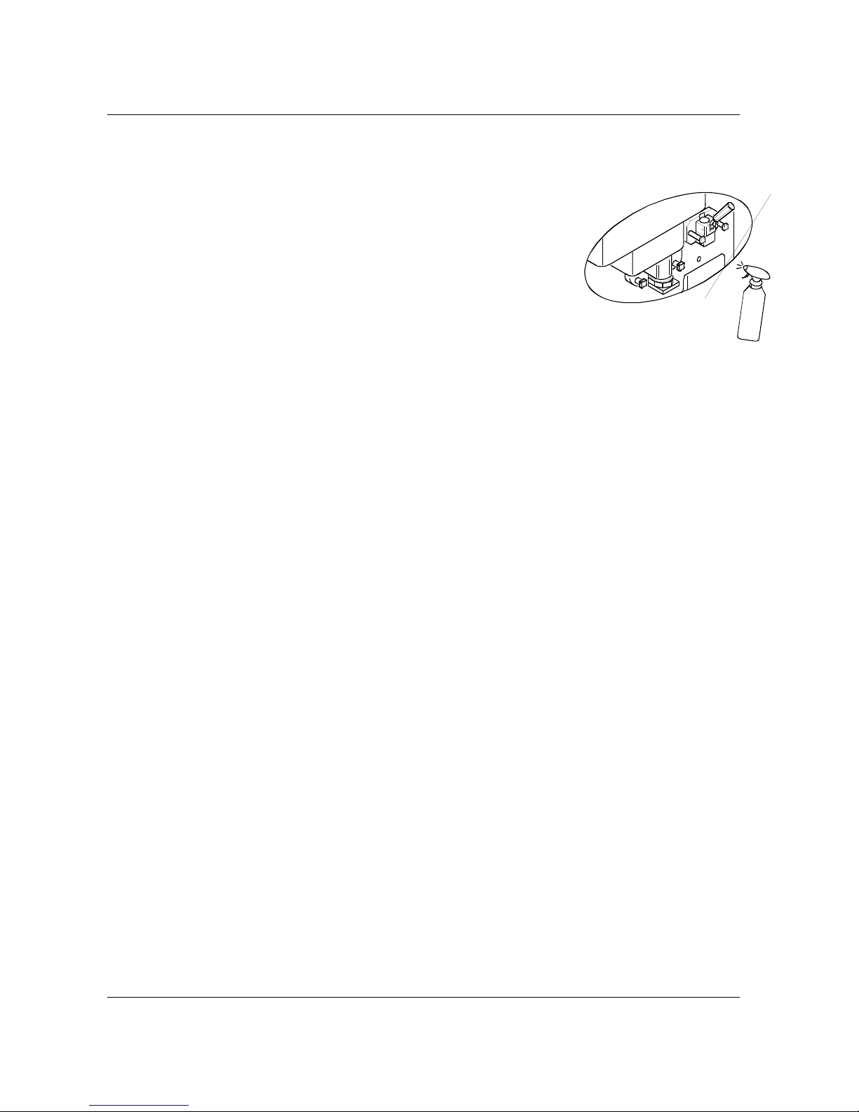
c) Spray the sanitising solution on the dispensing part, on the door
area, underneath the piston cover and all around the door.
d) Clean the external parts of th e machine with a clean and sanitizing
towel.
4.1.2 STARTING UP THE MACHINE:
The machine is in STOP function. Press the PROD button in order to start it up. The led will blink and
the starting up process is carried out for 15 minutes. During this time, you CANNOT dispense the
Shake. When “PROD” LED stays STILL, the Milk Shake is ready to serve.
WARNING
Do not keep any syrup line empty. In case you are using only 3 syrup flavours, you must close the hole
of the front lid using the tap delivered with the accessories as indicated in sect. 6.4.2.1 of the user’s
manual.
S
A
N
I
T
I
Z
E
R
Page 30
Carpigiani K 3 User’s guide
This manual is for the exclusive use of licensees and employees of McDonald’s Systems Inc Page 30 of 63
Version 5: October 2012
4.2 SUNDAE SIDE
Make sure your hands are clean and sanitized before performing the following procedures.
4.2.1
SANITIZING THE DOOR AREA:
a) Fill an empty pail with McD Sanitizer prepared in water at 70-90°F (21-
32°C) (1 packet in 2-1/2 gallons (9-1/2 litres) of water = 100 PPM) and
mix the powder
b) Return to the machine with some McD sanitizing solution in the
container.
c) Immerse the brushe s in the sanitising solution and wipe several times the
dispenser of the door, the same door, the area of the lever and all
around the door, including the holes of the knobs.
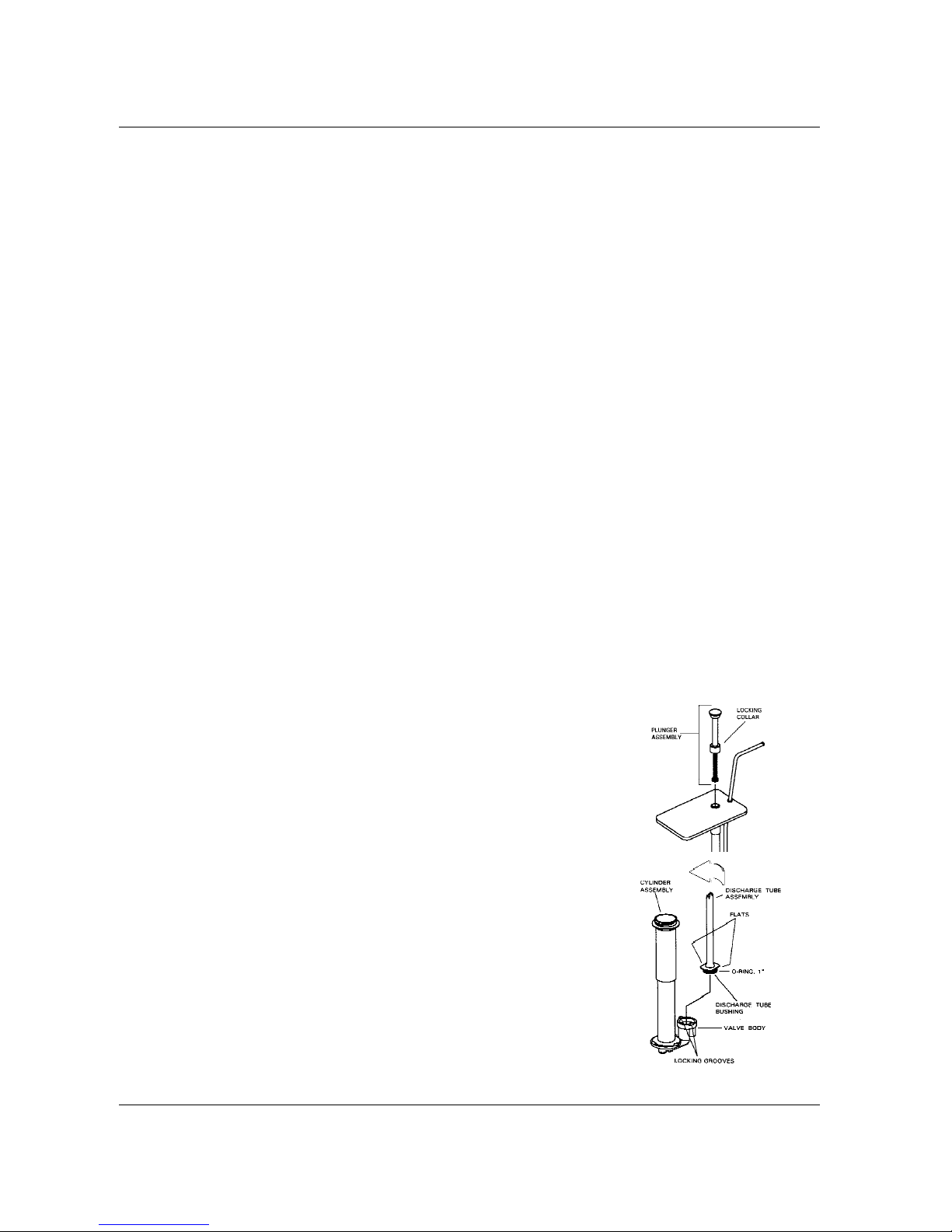
d) Spray the sanitising solution on the dispenser of the door, on the
surrounding area and on the same door.
e) Clean the front parts of the machine with a clean and sanitized towel.
4.2.2 PREPARING HOT TOPPINGS:
a) Remove the topping containers and check the water level. Fill the hot topping hopper with wate r
until the indicated level is reached. There is a level sensor inside the topping hopper, therefore
when the water level is low, an alarm message will be displayed. The alarm will persist until the
correct water level is reached.
b) Fill the containers with toppings, if necessary,
c) Place the covers and topping pumps in their seats (press the distribution pistons and discard the
first dispensed product). Once the machine is in PROD and the water level is sufficient, the
toppings will start to warm up.
d) As soon as the machine is in PROD. and the water level is satisfied the topping heaters will be
automatically on.
4.2.3 STARTING UP THE MACHINE:
The machine is in STORAGE mode. Press the STOP and th en the PROD buttons to start up th e machine.
You will be able to serve the sundae just in few minutes.
S
A
N
I
T
I
Z
E
R
Page 31
Carpigiani K 3 User’s guide
This manual is for the exclusive use of licensees and employees of McDonald’s Systems Inc Page 31 of 63
Version 5: October 2012
5. WEEKLY CLEANING
On a weekly basis, certain machine parts must be disassembled, washed, sanitized and reassembled. The following is the list of operations to be performed weekly in addition to the regular
daily cleaning procedure.
Make sure your hands are clean and sanitized before performing the following procedures.
5.1 WASHING AND SANITIZING OF THE TOPPING CONTAINERS
5.1.1 CLEANING OF THE TOPPING BINS:
a) Remove the topping pumps and bins from the machine and bring them to the back sink.
b) Discard the toppings weekly to break the bacterial life cycle.
c) Wash the bins thoroughly with the McD All Purpose Super Concentrate (APSC) and hot water 122-
140°F (50-60°C) (or with of hot McD APSC from the KayStar dispenser at the back sink),
eliminating any product’s residue.
d) Place the bins into the McD Sanitizer diluted with water at 70-90°F (21-32°C) [1 packet in 2-1/2 gal.
(9-1/2 liters) of water = 100 PPM] for 1 minute.
e) Make sure that the bins are empty and leave them out to air-dry.
5.1.2 CLEANING OFTHE TOPPING HOPPER
a) Place an empty container under the drain tap inside the syrup compartment.
b) Open the tap and drain the water completely from the tap. (caution: water is hot)
c) Close the tap.
5.2 DISASSEMBLING, WASHING AND SANITIZING OF THE HOT TOPPING PUMPS
Clean the hot-topping pumps:
Place the lower end of the pump into a container with clean warm water and operate the pump until
the discharged water is clear.
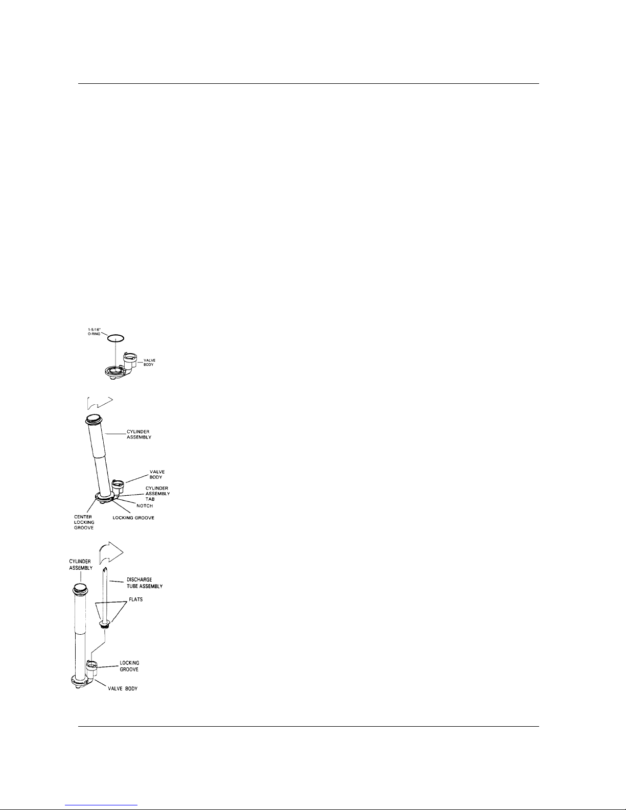
DISASSEMBLY
step 1
Loosen the locking collar until the plunger assembly can be removed from the
pump cylinder.
NOTE
The plunger spring is slightly compressed so be careful when removing the
knob.
step 2
Remove the discharge tube assembly by rotating it counter clockwise until the
flats on the discharge tube move away from the valv e bo dy locking grooves,
then pull the discharge tube assembly away from the valve body carefully.
step 3
Separate the O-ring from the discharge tube by pressing the O-ring and sliding
it in the joint groove until the O-ring can roll out from the groove.
step 4
Remove the cylinder assembly from the valve body by pressing downwards the
valve and rotate it counter clockwise at the same time until the tabs of the
cylinder assembly leave the locking grooves on the valve body.
step 5
Remove the O-ring from the valve body.
step 6
Place all parts in a clean container.
Page 32
Carpigiani K 3 User’s guide
This manual is for the exclusive use of licensees and employees of McDonald’s Systems Inc Page 32 of 63
Version 5: October 2012
WASHING
NOTE
DO NOT use tools that can s cratch polished surfaces. Do use clean and sanitized brushes instead.
step 1
Wash all pump components with the McD All Purpose Super Concentrate (APSC) and hot water at 122140°F (50-60°C) (or with hot McD APSC from the KayStar dispenser at the back sink).
step 2
Rinse them with clear water. Use the supplied brushes to clean the discharge tube assembly and the valve
body. It is recommended to wash the small parts in a pan or in any other similar container so they will not
get lost.
step 3
Sanitize the pump components immerging them in a container with McD Sanitizer diluted in water at 7090°F (21-32°C) [1 packet in 2-1/2 gal. (9-1/2 litres) of water = 100 PPM] (and mix the p owder)] the n, hold on
for 1 minute.
step 4
Allow the pump parts to air-dry after sanitizing.
REASSEMBLY
step 1
Lubricate and position the knob O-ring in its groove on the knob. Put the knob apart.
step 2
Assemble the washer, the spring, the head insert, and the head tube on the piston and
stem assembly.
step 3
Slip the cone shaped collars (if used) onto the head tube, then place the locking collar on
the head tube.
step 4
Hold the head tube and push the piston and stem assembly inside th e head tu be, compressing
the spring at the same time. When the threaded end of the stem projects through the head
tube, thread the knob onto the piston and onto the stem assembly.
Put the assembled plunger assembly apart.
step 6
Lubricate the O-ring with the appropriate lubricant and install the O-ring in its groove on
the discharge tube assembly joint. Temporarily put the discharge tube assembly apart.
step 7
Lubricate the O-ring with food grade lubricant and install the O-ring in its groove inside the
valve body.
step 8
Align the tabs on the cylinder flange with the notches in the valve body. Tilt the cylinder
assembly slightly and slide the widest section of the flange under the centre locking
groove of the valve body. Rotate the cylinder assembly clockwise and press it downwards
at the same time the flange tabs fully engage the locking grooves of the valve body.
step 9
Position the discharge tube assembly on the valve body, aligning the flats on the
discharge tube assembly’s joints with the locking tabs on the valve body. Push down the
discharge tube assembly until it is seated. Rotate the discharge tube assembly clockwise
to lock it in place.
step 10
Slide the lid onto the discharge tube assembly and onto the cylinder assembly and secure the lid
with the discharge tube nut.
step 11
Apply food grade lubricant onto the dischar ge fitti ng O-ring and ins tall the O-ri ng on the plan t.
Install the plant on the discharge tube by pushing it inside and rotating it in a clockwise
direction.
step 12
Apply a small amount of food grade lubricant to the seal flare, install the plunger assembly
in the pump body assembly, and tighten the locking collar.
Page 33

Carpigiani K 3 User’s guide
This manual is for the exclusive use of licensees and employees of McDonald’s Systems Inc Page 33 of 63
Version 5: October 2012
5.3 CHECK TOPPING PUMP TEMPERATURE AND VOLUME
NOTE
This procedure should be performed in the morning when the pumps are disassembled and cleaned.
step 1
Dispense one serving of topping into a sundae cup and discard this portion of material.
step 2
Dispense the second serving into a sundae cup in the same way.
step 3
Insert the digital thermometer into the topping. Let the digital thermometer stabilize for 20 seconds.
NOTE
: Topping temperature must be between 115 and 125F (46 and 52C) and must remain in this
range before the calibration pump starts. The water temperatur e of the bath must be between 135
and
145
F (57 and 63C).
step 4
If the temperature is too cold or too warm, call service to adjust it.
step 5
Hold the small chamber of the calibrating cup exactly under the dispensing nozzle.
step 6
Push the dispensing lever down firmly. The topping must come to the bottom of the calibrating cup. Do not allow the
topping to slide down on the sides of the cup.
NOTE: The amount of dispensed topping should be one fluid ounce (29.6 ml).
step 7
If the amount of dispensed topping is not correct, consult the troubleshooting section of your equipment’s manual.
step 8
Repeat for the other topping pump.
Page 34

Carpigiani K 3 User’s guide
This manual is for the exclusive use of licensees and employees of McDonald’s Systems Inc Page 34 of 63
Version 5: October 2012
6. EVERY 14 DAYS CLEANING
After exactly 14 DAYS from the last brush cleaning, the machine must be thoroughly washed and
restarted. It automatically locks out and must be disassembled, washed, sanitized and reassembled before
operations can resume. Every time product is dispensed the display indicates the number of days to the
next brush cleaning.
THE FOLLOWING IS THE LIST OF OPERATIONS TO BE PERFORMED ON THE 14
TH
DAY IN
ADDITION TO THE REGULAR DAILY AND WEEKLY CLEANING PROCEDURE.
NOTICE
MAKE SURE YOUR HANDS ARE CLEAN AND SANITIZED.
6.1 DISASSEMBLING AND CLEANING THE MILK SHAKE SIDE
NOTICE
ALL PARTS REMOVED FROM THE MACHINE SHOULD BE PLACED INTO A CONTAINER, AND
TRANSPORTED TO THE SINK FOR CLEANING, RINSING AND SANITIZING.
6.1.1 CLEANING THE SHAKE SYRUP SYSTEM
Wiping pick up tubes:
a) Remove the syrup pick up tubes from the syrup jugs or disconnect the syrup connector from the
syrup bag.
b) Wipe the outside of the pick up tubes with a clean, sanitized towel. Remove the syrup jugs/syrup
bags from the syrup compartment.
Cleaning the syrup lines:
a) Remove the cup holder and place an empty pail under the door spout.Fill a pail with the McD All
Purpose Super Concentrate (APSC) and hot water 122-140°F (50-60°C) (or refill a pail of hot McD
APSC from the KayStar dispenser at the back sink).
b) Place the pick up tubes inside. Press STOP then push the corresponding “coloured cup” button
two times to run the syrup pump at maximum speed and let the water flow for 1 minute. Press
STOP button to stop the syrup pump.
c) Repeat for all syrup lines.
Rinsing the syrup lines:
a) Fill a pail with tap water and place the pick up tubes inside. Push the corresponding “coloured cup”
button two time and let the water flow for 1 minute. Press STOP button to stop the syrup pump.
b) Repeat for all syrup lines.
Page 35
Carpigiani K 3 User’s guide
This manual is for the exclusive use of licensees and employees of McDonald’s Systems Inc Page 35 of 63
Version 5: October 2012
6.1.2 DRAINING AND CLEANING THE MILK SHAKE SIDE
WARNING
Every time the display shows “WASH TODAY” alarm, you have to push
once the
button in order to reset the ala r m me ssa g e .
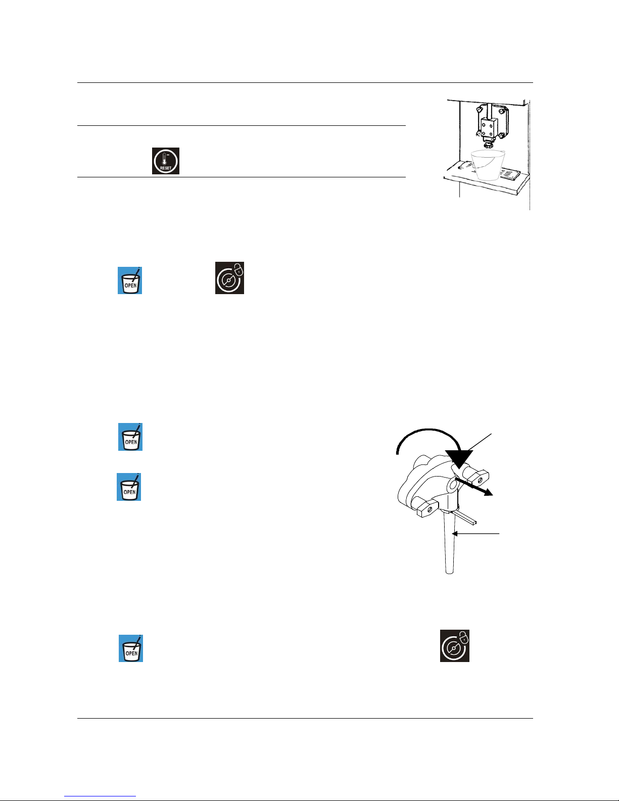
Drain the Milk Shake
step 1
Put an empty pail under dispensing spout.
step 2
Push the “STOP” button.
step 3
Push the
button then push button to allow the milk shake to flow out until it becomes liquid.
step 4
Push the “STOP” button to close the piston, stop the beater mot or and the m ix pump.
step 5
Remove the pressure tube:
In the hopper, disconnect the pressure tube from the pump, turn it sideways and remove it by pulling it up
from its seat.
Remove the mix pump:
Grasp the pump and turn it in a clockwise direction of 45° then pull it out towards you. Make sure that the
pump drive shaft and seal are taken out with the pump.
Remove the mix agitator:
Remove the agitator from the hopper by pulling it upwards.
step 6
Push the
button in order to open the piston and drain the rest of
the liquid mix.
step 7
Use the
button to open and close the piston when necessary
while still in STOP. Drain the hopper completely. To close the piston,
press the “STOP” button.
step 8
Rinse the machine
Pour 2,5 gallons (9.5 liters) of cool, clean water into the mix hopper.
Use the white hopper brush to scrub the mix hopper, mix level sen sor
and the outside the agitator shaft.
Use the small brush to clean the mix inlet hole and the drive hub of the
mix pump.
step 9
Drain rinse water from hopper and cylinder
Place an empty pail under the milk shake spout.
Push the
button to open the spigot piston and le t the water drain out. Press the button and
let the beater run for about 10 seconds. Press the “STOP” button to stop the beater; the piston closes
automatically.
Pump body
Feeding
tube
Page 36
Carpigiani K 3 User’s guide
This manual is for the exclusive use of licensees and employees of McDonald’s Systems Inc Page 36 of 63
Version 5: October 2012
Push the button to open the spigot piston and let the water flow completely out.
Repeat steps 8 and 9 until the rinse water being dispensed is clear.
step 10
Clean the machine
Fill the tank with 2-1/2 gallons (9-1/2 litres) of warm water APSC solution.
step 11
Press the
button and let the beater run for about 10 seconds.
step 12
Push the “STOP” button.
step 13
Use the appropriate hopper brush to scrub the mix hopper, mix level sensor and the outsid e the agitator
shaft.
Use the small brush to clean the mix inlet hole and the drive hub of the mix pump.
step 14
Push the
button and let the liquid flow completely out.
step 15
Then push the “STOP” button to close the piston.
step 16
Rinse the machine
Rinse with clear water, push the
button and let the water flow completely out. Press the “STOP”
button to close the piston.
step 17
Sanitizing the machine
Fill the hopper with McD Sanitizer prepared in water 70-90°F (21-32°C) [1 packet in 2-1/2 gal. (9-1/2 liters)
of water = 100 PPM].
step 18
Press the
button and let the beater run for 10 seconds then push STOP.
Use the appropriate hopper brush to scrub the mix hopper, mix level sensor and the outsid e the agitator
shaft.
Use the small brush to clean the mix inlet hole and the drive hub of the mix pump.
step 19
Leave the solution of McD Sanitizer for a minimum of 1 minute.
step 20
Push the “
” button and let the sanitizer flow completely out.
step 21
Push the “STOP” button.
Page 37
Carpigiani K 3 User’s guide
This manual is for the exclusive use of licensees and employees of McDonald’s Systems Inc Page 37 of 63
Version 5: October 2012
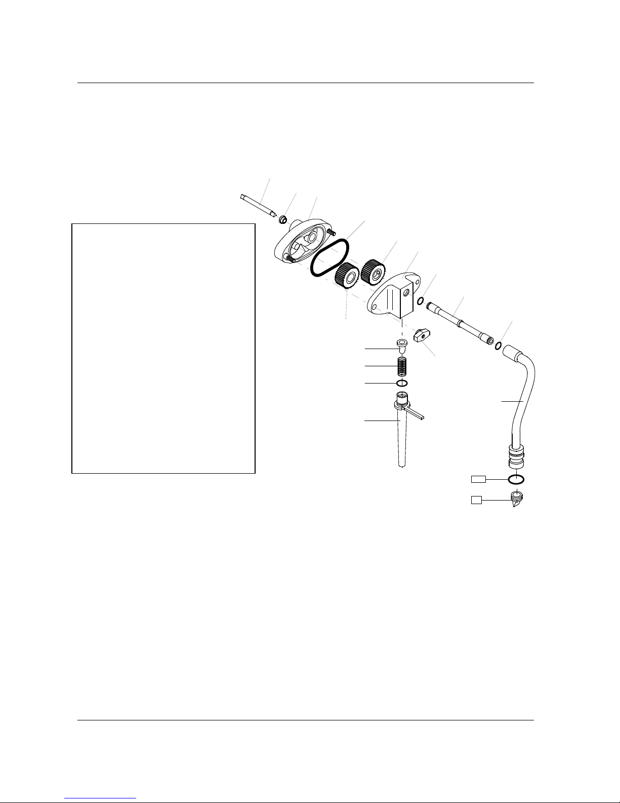
6.1.3 DISASSEMBLING OF THE SHAKE MIX PUMP
step 1
Remove the pump drive shaft and seal from the pump.
step 2
By holding the feeding tube (#271A) upwards turn it counter-clockwise and pull it out.
step 3
Using the O-ring extractor, remove the O-ring (#1412). Remove the spring (#206A) and the back flow valve
(#245).
step 4
Unscrew the 2 knobs (#8B) and separate the cover (#202A) from the pump body (#39A).
step 5
Using the or-ring extractor, remove the large O-ring (#1178). tapping the pump body against the palm of
your hand, remove the pump gears (#38 and 38A).
step 6
Pull out the connection tube (#207) from the pressure pipe(#32A).. Remove the O-rings (#1131 and 1117)
and the duck bill valve (#31).
Pos. Description
8B Hand screws
31 Check valve-slit
32A Pressure pipe
38 Driving gear
38A Driven gear
39A Pump body
96 Pump shaft
100 Shake chamber tube
202A Pump housing
206 Spring
207 Connection tube
271A Feeding tube
243 Seal-mix pump shaft
245 Pressure relief valve
1104 O-ring
1117 O-ring
1131 O-ring
1178 O-ring
1412 O-ring
1416 O-ring
202A
39A
38A
1178
1117
38
245
206A
1412
271A
207
1117
32A
1131
96
243
31
8B
Page 38
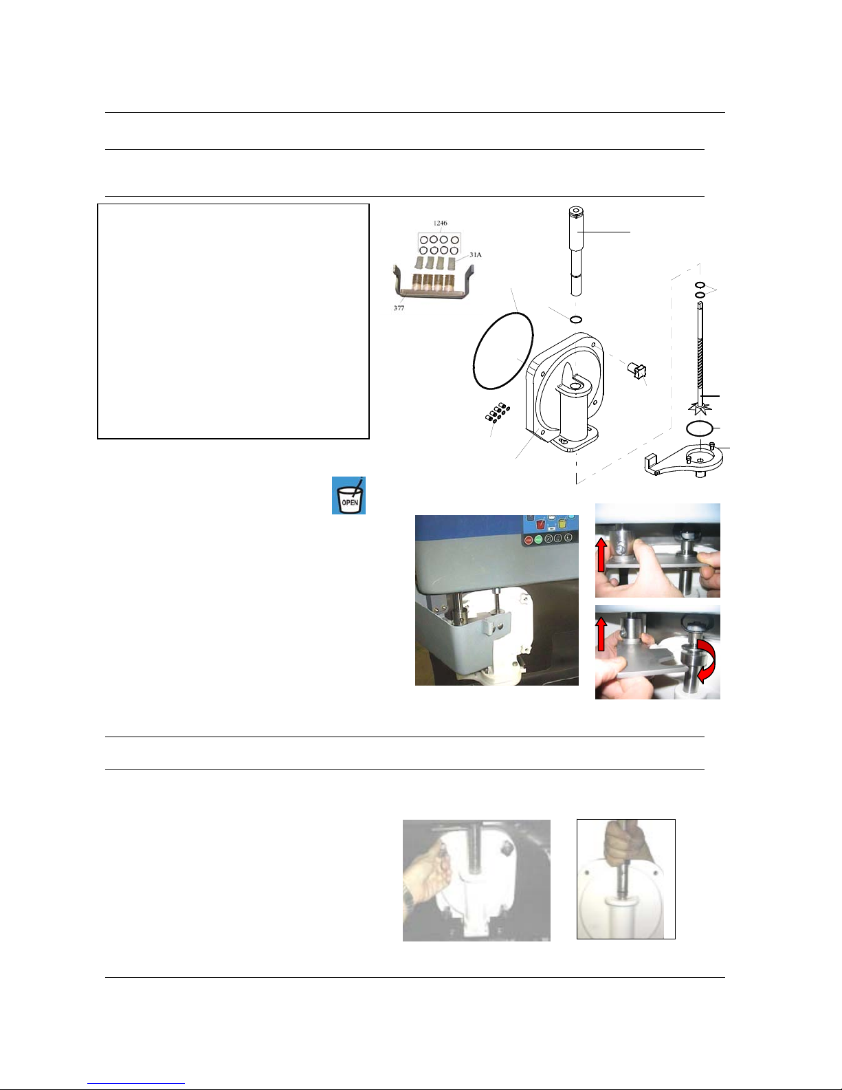
Carpigiani K 3 User’s guide
This manual is for the exclusive use of licensees and employees of McDonald’s Systems Inc Page 38 of 63
Version 5: October 2012
A
6.1.4 DISASSEMBLING OF THE SHAKE DISPENSING DOOR
CAUTION
Before disassembling the dispensing head, make sure that the hopper and
the cylinder are completely drained.
Pos. Description
7A Dispensing door
8A Hand screws
30A Piston
31A Syrup duck bill valves
369 Spinner
370 Spout cap
377 Syrup valves support
1109 O-ring
1195 O-ring
1130 O-ring
1142 O-ring
1240 O-ring
1246 O-ring
step 1
With the machine in STOP mode, push
button
to open the piston
step 2
Open the protection cover (ref. C).
step 3
Slide the cylinder up with the fingers (ref. A) and turn
the bracket clockwise (ref. B).
Step 4
Remove the cup holder.
Step 5
Twist the spout cap (#370) clockwise then pull it
down in order to remove it (the warning IMSB OPEN
flashs on the display)
step 6
Slide the spinner out (#369).
CAUTION
Be careful not to drop the spinner: it may be seriously damaged.
step 7
Unscrew the four knobs retaining door (#8A) and remove the dispensing door from the four studs by pulling
it towards you. (Fig. 4)
step 8
Remove the valve block (#377) sliding it down.
step 9
Remove the 4 o-rings (#1109) from syrup outlet
on the front of the machine
step 10
Holding the dispensing door (#7A) straight up,
remove the piston by pulling it upward (Fig. 5).
1240
30A
369
1253
370
1130
1195
7A
8A
1109
B
C
4 5
Page 39
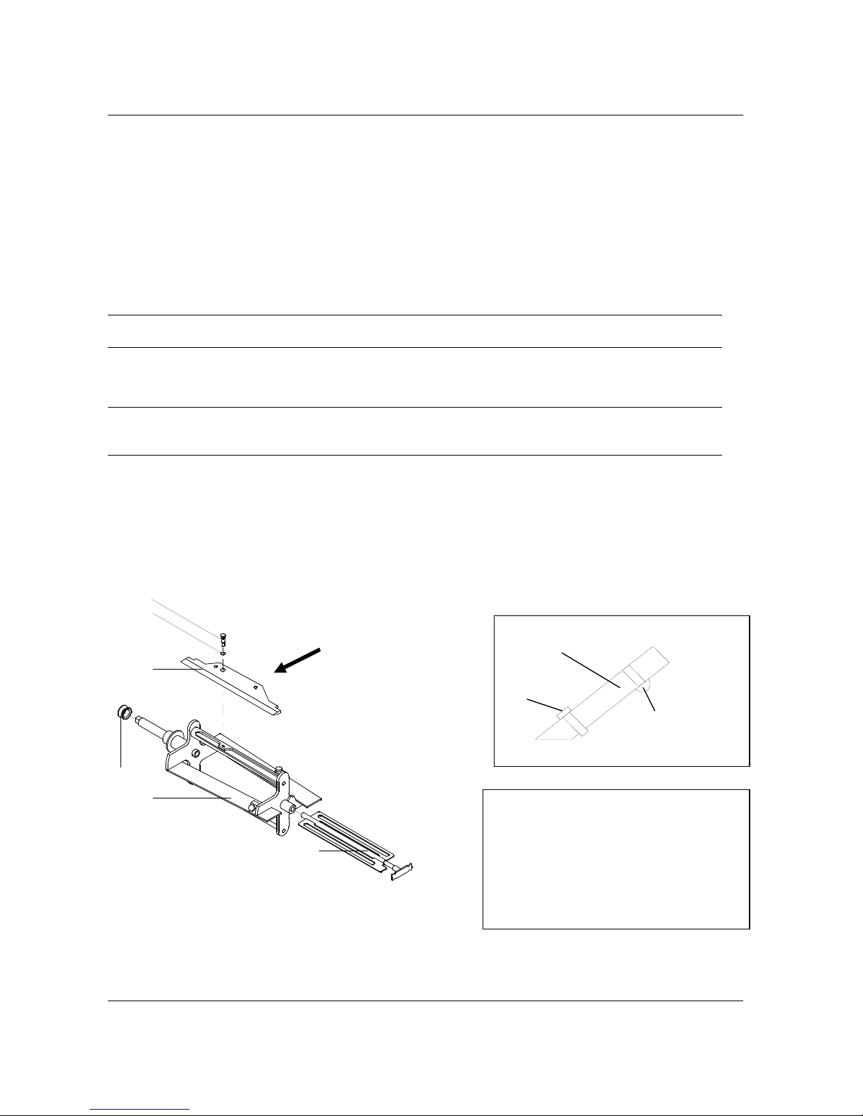
Carpigiani K 3 User’s guide
This manual is for the exclusive use of licensees and employees of McDonald’s Systems Inc Page 39 of 63
Version 5: October 2012
step 11
Using the O-ring extractor, remove:
a) the piston O-ring (#1130).
b) the door O-ring (#1195).
c) the 2 piston housing O-rings (#1240) located inside the dispensing door.
d) the spout cap plate O-ring (#1253).
e) Remove the duck bill valves and the 8 o-rings (#1246) of the syrup valve block.
6.1.5 DISASSEMBLING OF THE SHAKE CYLINDER’S BEATER
step 1
Remove the shake beater (#21) from the cylinder pulling it towards you.
CAUTION!
Be careful not to hit the cylinder walls with the shaft of the beater when pulling it out.
step 2
Slide the beater seal (#28) out of the beater shaft.
CAUTION!
Make sure that the beater seal is in its place and be careful not to lose it and to reas se m ble it after
washing.
step 3
Remove the idler (#24A) from the beater frame (#21A).
step 4
Remove the beater blade pin (#726) pulling it upward and remove the blade (#430). Carpigiani suggests to
replace the blade once a year (please see the tune-up kit card).
step 5
Remove the pin O-ring (#1271)..
Rubber stoppers
Beveled
blade
Pin
A
Pos. Description
21 Beater
24A Counter beater
28A Stuffing box (beater seal)
430A Beater blade
726 Beater blade pin
1271 O-ring
21A
24A
28A
1271
726
430A
A
Page 40
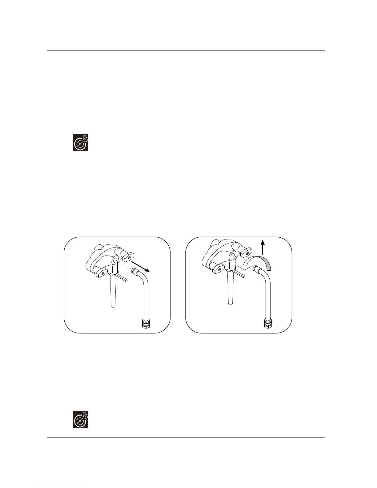
Carpigiani K 3 User’s guide
This manual is for the exclusive use of licensees and employees of McDonald’s Systems Inc Page 40 of 63
Version 5: October 2012
6.2 DISASSEMBLING AND CLEANING OF THE SUNDAE SIDE
6.2.1 DRAINING AND CLEANING OF THE SUNDAE SIDE
Drain the machine
step 1
Place an empty pail under the SUNDAE spout.
step 2
Press the “STOP” button.
step 3
Pull the dispensing lever and drain the ice cream.
step 4
Press the
button.
step 5
When the product coming out becomes liquid, push the “STOP” button and leave the spout open.
step 6
Remove the pressure tube
In the hopper, disconnect pressure pipe from the mix pump, turn it sideways, remove it pulling it up from its
seat and let the product flow completely out.
Remove the mix pump:
Grasp the pump and turn it in a clockwise direction of 45° then pull it out towards you. Make sure that the
pump drive shaft and its seal are taken out with the pump.
Remove the mix agitator:
Remove the agitator by pulling it upwards
step 7
Rinse the machine
Close the spout handle, pour 2,5 gallons (9.5 liters) of cool, clean water into the mix hopper.
Use the appropriate hopper brush to scrub the mix hopper, mix level sensor a nd the outside axe of the
agitator shaft. Use the small brush to clean the mix inlet hole and the drive hub of the mix pump.
Drain rinse water from hopper and cylinder
Place an empty pail under spout. Open the spigot piston and let the water drain out.
step 8
Rinse with warm water until the solution runs clear.
step 9
Press the
button and let the beater run for 10 seconds .
2
3
1
Page 41

Carpigiani K 3 User’s guide
This manual is for the exclusive use of licensees and employees of McDonald’s Systems Inc Page 41 of 63
Version 5: October 2012
step 10
Turn the machine off by pushing the “STOP” button and let the water flow out.
step 11
Clean the machine
Fill the hopper with 2-1/2 gallons (9-1/2 litres) of warm APSC solution.
step 12
Clean the hopper walls, the level sensor and outside of the agitator shaft using the supplied brushes.
step 13
Pull the dispensing handle and let the liquid flow out completely.
step 14
Rinse the machine
Rinse with clear water, pull the spigot handle and let the water flow out.
step 15
Sanitize the machine
Fill the hopper with McD Sanitizer prepared in water 70-90°F (21-32°C) [1 packet in 2-1/2 gal. (9-1/2 liters)
of water = 100 PPM].
step 16
Press
button and let the beater run for 10 seconds.
Use the appropriate hopper brush to scrub the mix hopper, mix level sensor and the outside of the agitator
shaft.
Use the small brush to clean the mix inlet hole and the drive hub of the mix pump.
step 17
Push the “STOP” button. Let the McD Sanitizer solution stand for at least 1 minute.
step 18
Pull the dispensing handle and let the water flow completely out.
Page 42
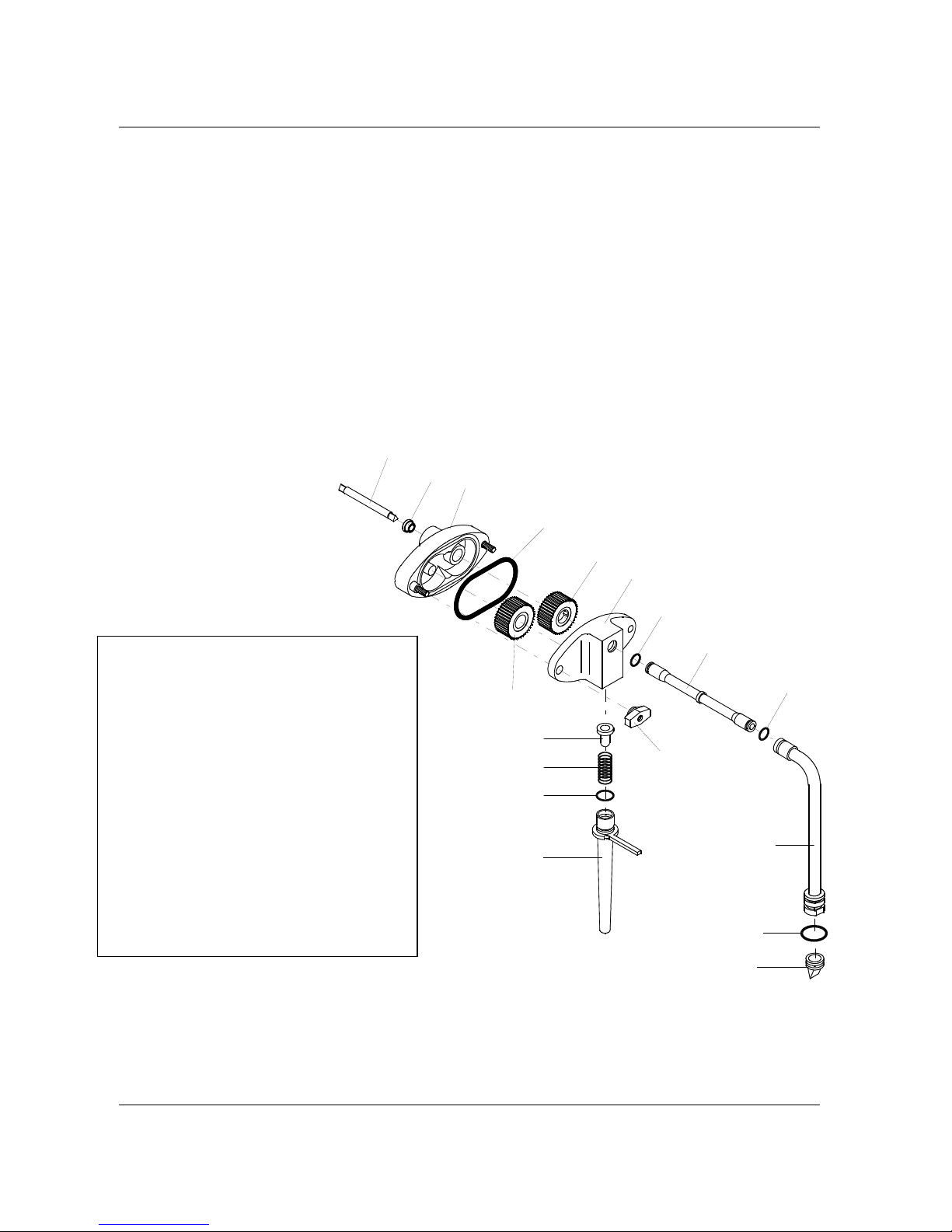
Carpigiani K 3 User’s guide
This manual is for the exclusive use of licensees and employees of McDonald’s Systems Inc Page 42 of 63
Version 5: October 2012
6.2.2 DISASSEMBLING OF THE MIX PUMP
step 1
Remove drive shaft (#96) and seal (#243).
step 2
Keeping the feeding tube (#271) upward turn it counterclockwise and pull it out.
step 3
Pull the spring (#206) and the back flow valve (#245 ) out. Using the o-ring extractor, remove the O-ring
(#1412).
step 4
Unscrew the 2 knobs (#8B) and separate the cover (#202) from the pump body (#39).
step 5
Using the o-ring extractor, remove the large O-r ing (#1178). Tapping the pump body against the palm of
your hand, remove the pump gears (#38-#38A).
step 6
Pull the connection tube (#207) from the pressure pipe (#32). Remove the O-rings (#1131 and 1117) and
the duck bill valve (#31).
Pos. Description
8B Hand screws
31 Check valve-slit
32 Pressure pipe
38 Driven gear
38A Driving gear
39 Pump hosing – rear
96 Pump drive shaft
202 Pump hosing - front
206 Spring
207 Connection tube
243 Seal mix pump drive shaft
245 Pressure relief valve
271 Feeding tube
1117 O-ring
1412 O-ring
1416 O-ring
202
39
38A
1178
1117
38
245
206
1412
271
207
1117
1131
96
243
31
8B
32
Page 43
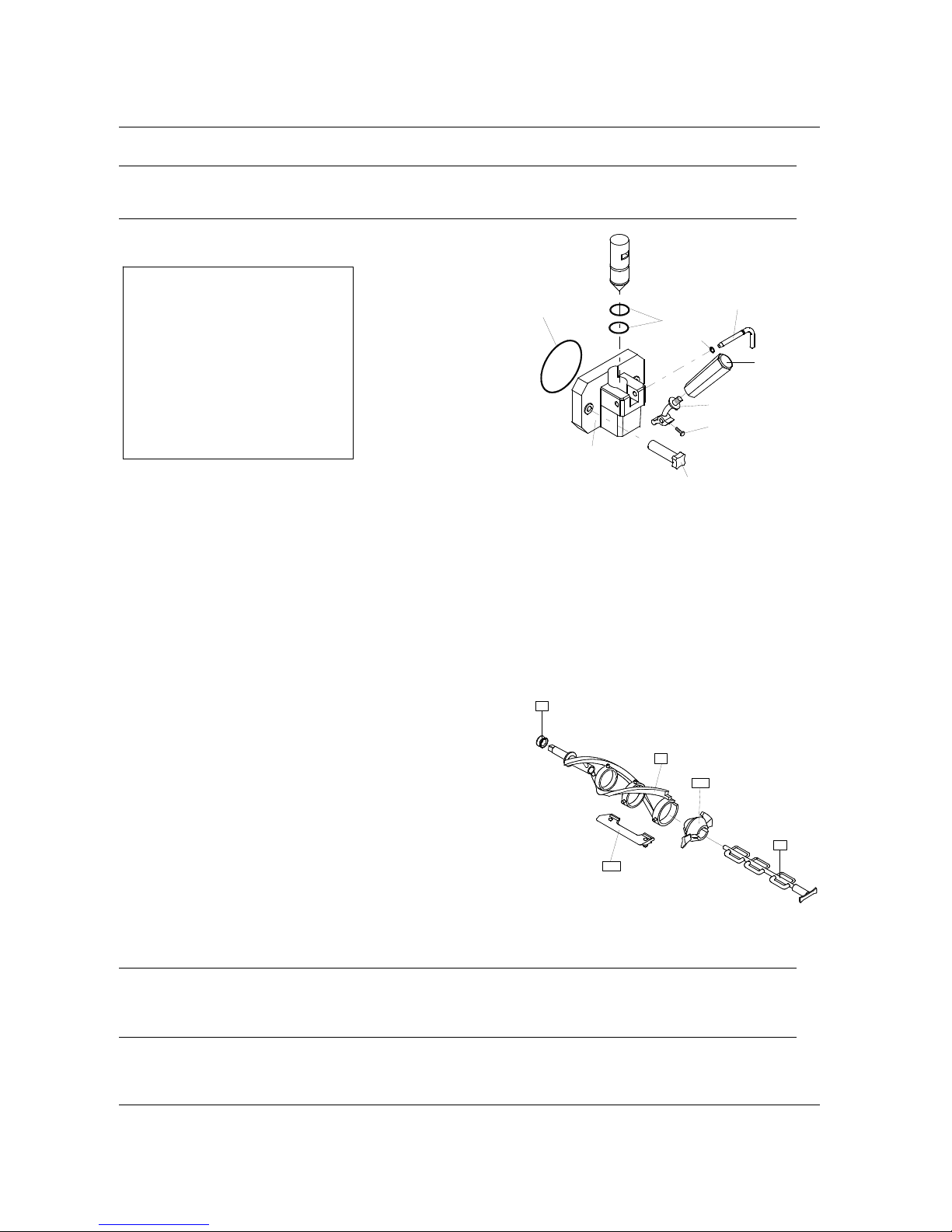
Carpigiani K 3 User’s guide
This manual is for the exclusive use of licensees and employees of McDonald’s Systems Inc Page 43 of 63
Version 5: October 2012
6.2.3 DISASSEMBLING OF THE SUNDAE DISPENSING DOOR
CAUTION
Before disassembling the dispensing head, make sure that the hopper
and the cylinder are completely drained.
step 1
With the machine in STOP mode, remove two retaining knobs (#8) and pull the door assembly towards you
sliding it off the two front panel st uds.
step 2
Remove the pivot O-ring (#1289)
step 3
Pull the dispensing handle (#5) so the piston (#30) raises in its housing and pull the pivot pin (#6) out
releasing the dispensing handle (#5).
step 4
Using the dispensing handle lever, pull the piston (#30) out completely .
step 5
Using the o-ring extractor, remov e:
a) the 2 piston O-rings (#1153)
b) the large dispensing door O-ring (#1188).
6.2.4 DISASSEMBLING OF THE SUNDAE BEATER
step 1
Pull the beater (#21) out of the cylinder.
step 2
Slide the beater seal (#28) out of the beater shaft.
step 3
Pull out and remove the end pusher (#25P) and the idler (#24).
step 4
Remove the 3 beater blades (#430). Carpigiani suggests to replace the blad es each 6 months (p lease see the
tune-up kit card).
CAUTION
The beater seal is very important. It must be checked regularly for wear and tear. It must always be
on the beater shaft and properly lubricated, during operation, otherwise mix will leak in the drip
tray.
Pos. Description
5 Dispensing handle
6 Handle pin
7 Soft serve door
8 Handscrews
30 Dispensing piston
43 Piston lever
1153 O-ring
1188 O-ring
1289 O-ring
1188
7
1289
214
43
5
6
1153
8
28
21
24
25P
430
Page 44
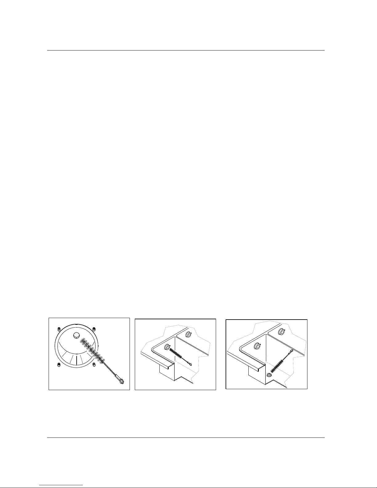
Carpigiani K 3 User’s guide
This manual is for the exclusive use of licensees and employees of McDonald’s Systems Inc Page 44 of 63
Version 5: October 2012
6.3 WASHING AND SANITIZING OF COMPONENT PARTS
step 1
Fill a clean sink with the McD All Purpose Super Concentrate (APSC) and hot water 122-140°F (50-60°C)
(or with hot McD APSC from the KayStar dispenser at the back sink).
step 2
Wash the disassembled parts with the APSC solution and scrub them thoroughly with the brushes
provided with the machine. As you proceed, rinse with h ot water. Make sure all lubricant and mix film is
removed from parts.
step 3
Fill another sink with McD Sanitizer prepared in water 70-90°F (21-32°C) [1 packet in 2-1/2 gal. (9-1/2
litres) of water = 100 PPM].
step 4
Place the parts in the sanitizing solution. Leave them there for at least 1 minute.
step 5
Place the components on the milk shake tray to air-dry.
step 6
Place the sundae components on the sundae tray to air-dry.
step 7
Return to the machine with a small amount of McD Sanitizer.
step 8
Dip a brush into the sanitizer and thoroughly brush both freezing cylinders.
step 9
Dip a brush into the sanitizer and thoroughly brush clean the mix inlet hole and the pump drive hub
openings in the rear of both mix hoppers.
Step 10
Spray the back of cylinder with sanitizer.
Page 45
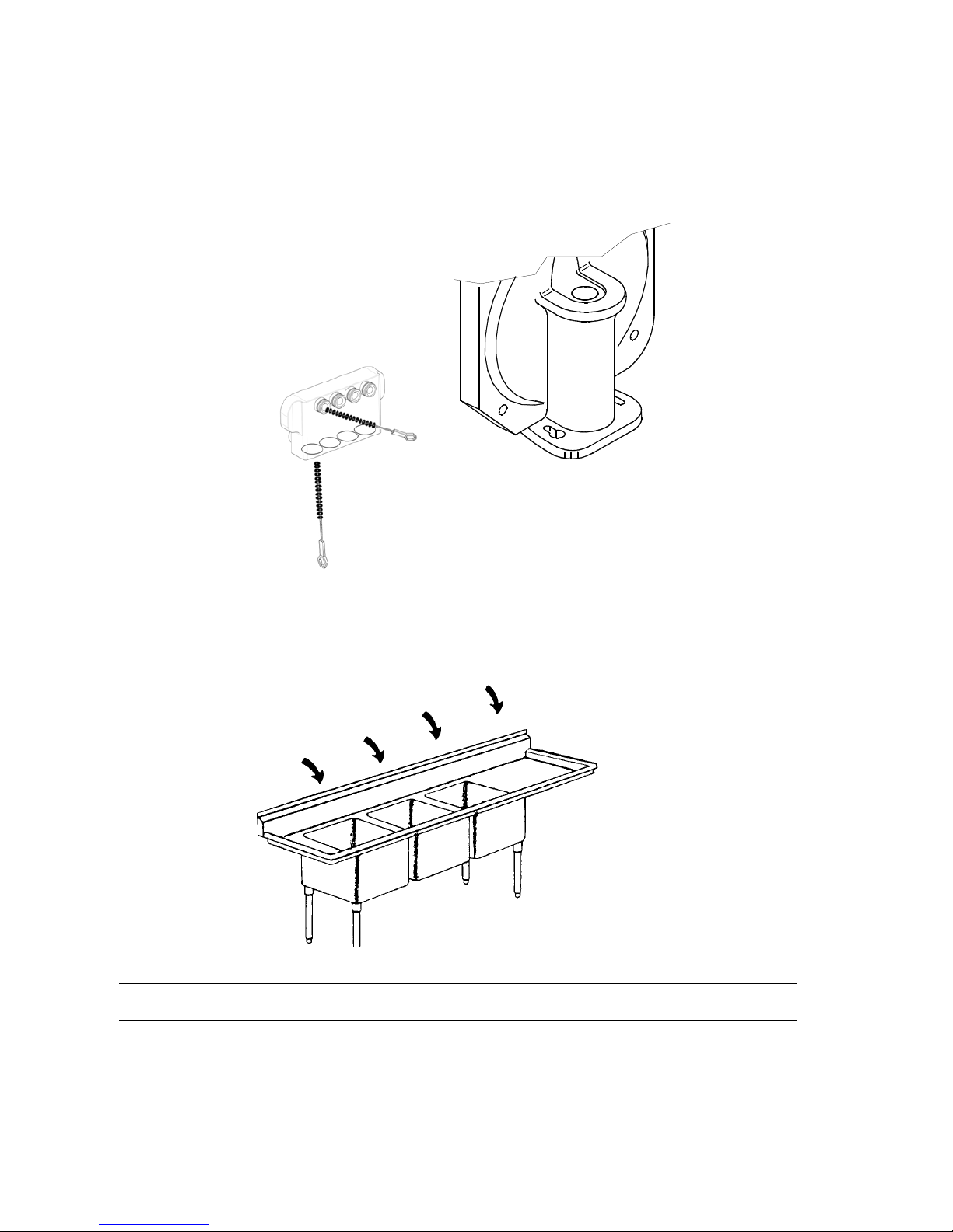
Carpigiani K 3 User’s guide
This manual is for the exclusive use of licensees and employees of McDonald’s Systems Inc Page 45 of 63
Version 5: October 2012
3) Sanitize
4) Air-Dry
1) Wash
step 11
Dip a brush into the sanitizer solution thoroughly brush clean the syrup injectors located on the front panel
just under the milk shake cylinder.
Repeat steps 8 , 9 and 10 several times.
IMPORTANT!!
We recommend not to wash the sundae and shake components together.
2) Rinse
Page 46
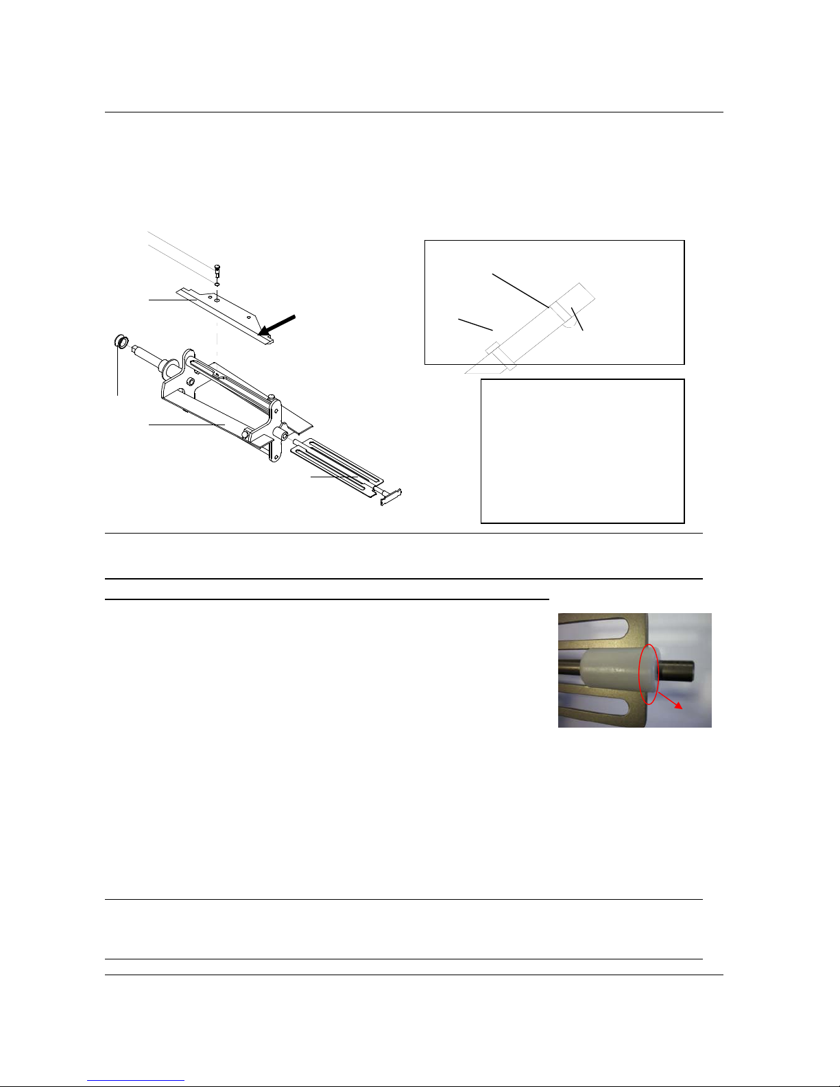
Carpigiani K 3 User’s guide
This manual is for the exclusive use of licensees and employees of McDonald’s Systems Inc Page 46 of 63
Version 5: October 2012
6.4 REASSEMBLY OF WASHED AND SANITIZED COMPONENT PARTS
6.4.1 REASSEMBLY OF THE SHAKE CYLINDER BEATER
step 1
Lubricate the blade pin O-ring (#1271) and slide it onto the pin (#726).
CAUTION!
Check the rubber stoppers onto the blade for integrity. Replace if worn or damaged.
Carpigiani suggests to replace the blade once a year (please see the tune-up kit card).
WARNING
Like all moving parts, the complete beater is also subject to wear and tear.
For this reason, we recommend checking the amount of wear to parts in
direct contact with one an-other (beater/beater idler and beater/cylinder
walls) on a regular basis during scheduled cleaning operations and in any
case, every six months of machine operation.
In particular, make sure that the wear on the bushing on the beater idler is
no more than 2 mm, as indicated b y the markin g on the bushin g itself. I f
there is more than 2 mm wear, it is necessary to replace the beater idler.
step 2
Place the blade (#430A) in its housing on the beater (#21A) aligning the pin hole with the hole on the
beater. Secure the blade (#430A) onto the beater (#21A) inserting the b eater blade pin (#726) into the
blade and the beater hole. The head of the rubber stoppers should rest on the beater frame.
step 3
Replace the idler (#24A) in the beater frame (#21A) first inserting the front shaft into the slot of the beater front housing
and then inserting th e idler shaft int o the rear housing. Push it towards th e back, otherw ise the idler may fall out.
step 4
Lubricate the sides of the beater seal (#28A) and slide it onto the beater shaft.
CAUTION!
The beater seal is very important. It must be checked regularly for wear and tear. It must always be
on the beater shaft and properly lubricated, during operation, otherwise mix will leak in the drip
tray.
A
Pos. Description
21A Beater
24A Counter beater
28A Beater seal
430A Beater blade
726 Beater blade pin
1271 O-ring
Rubber stoppers
Beveled
blade
Pin
A
21A
24A
28A
1271
726
430A
Marking line
Page 47
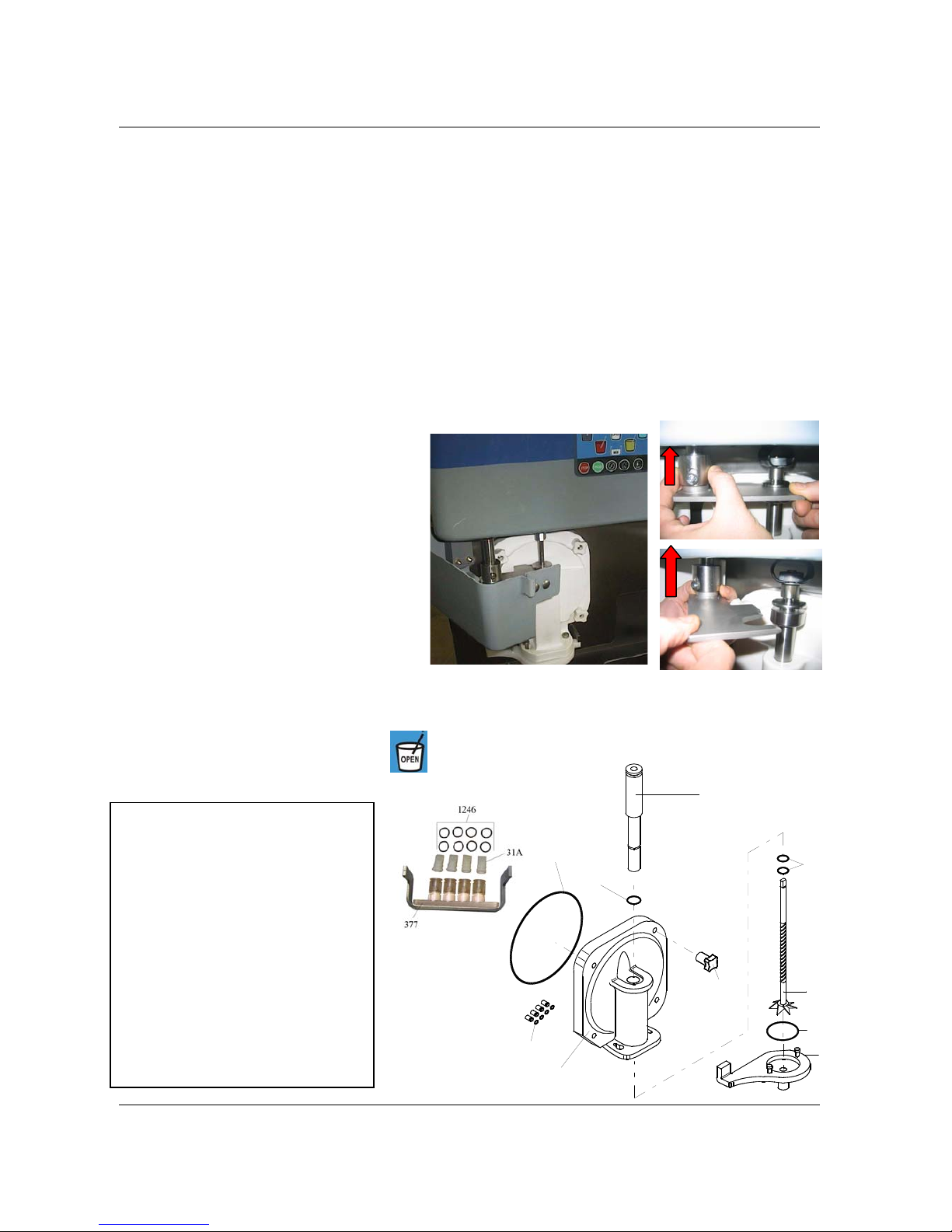
Carpigiani K 3 User’s guide
This manual is for the exclusive use of licensees and employees of McDonald’s Systems Inc Page 47 of 63
Version 5: October 2012
A
B
C
step 5
Insert the beater assembly into the cylinder, push it to the end and rotate it slightly until its shaft ente rs the
rear hub: the self adjusting blade should be inside the rim of the cylinder.
6.4.2 REASSEMBLY OF THE SHAKE DISPENSING DOOR
step 1
Lubricate and replace the 4 syrup outlet o-rings (#1109) on the front panel of machine.
step 2
Lubricate the O-rings and replace them in their respective position i.e.:
a) Replace the 8 o-rings (#1246) on the syrup distribution block (#377),
b) Replace the 4 duck bill valves (#31A) on the syrup distribution block (#377),
c) Replace the syrup distribution block (#377) in its position on the front panel of the machine,
d) Replace the 2 piston housing O-ring (#1240) in the dispensing door,
e) Replace the O-ring (#1130) on the piston,
f) Replace the O-ring (#1195) on the dispensing door,
g) Replace the O-ring (#1142) on the spinner plate
step 3
Holding the dispensing door (#7A) upward,
lubricate and replace the piston (#30A) in its
position in the front door.
step 4
Fit the dispensing door (#7A) in the four front
panel studs and fasten it w ith the fou r kno bs (#8A)
hand-tightening them in alternate sequence.
step 5
Lubricate the spinner shaft and insert the
spinner (#369) into its housing.
step 6
Mount the spinner plate (#370).
step 7
Move up the spigot piston, slide up the cylinder
(ref. A) and close the bracket (ref. B) on the
piston.
step 8
Close the protection cover (ref. C). Ensure cover is closed properly otherwise the machine will not operate.
step 9
With the machine in STOP mode push the
button to close the piston.
Pos. Description
7A Dispensing door
8A Hand screws
30A Piston
31A Syrup duck bill valves
369 Spinner
370 Spout cap
377 Syrup valves support
1109 O-ring
1195 O-ring
1130 O-ring
1142 O-ring
1195 O-ring
1240 O-ring
1246 O-ring
1240
30A
369
1253
370
1130
1195
7A
8A
1109
Page 48
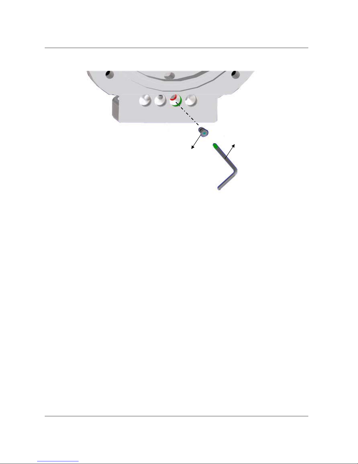
Carpigiani K 3 User’s guide
This manual is for the exclusive use of licensees and employees of McDonald’s Systems Inc Page 48 of 63
Version 5: October 2012
6.4.2.1 Shake side warning – When using only 3 syrups.
In case you are using only 3 syrup flavours, you should close the hole of the front lid using the tap ref. 1
delivered with the accessories.
This step can fit only in the hole indicated by X in the fig.
To block it firmly use the key ref. 2.
By doing so, the forth syrup flavour that corresponds to the blue cup button becomes disabled.
The tap and its o-ring should be disassembled, cleaned and sanitized during the periodical cleaning.
6.4.3 REASSEMBLY OF THE SHAKE MIX PUMP
step 1
Lubricate and replace the O ring (#1117) on the connection tube (#207).
step 2
Lubricate and replace the O-ring (#1131) and the duck bill valve (#31) on the pressure pipe (#32A).
step 3
Insert the connection tube assembly in the pressure pipe (#32A).
step 4
Place the pressure pipe in a sanitizing solution.
step 5
Insert the pump gears (#38-#38A) into the pump body (#39A).
step 6
Lubricate and replace the pump body O-ring (#1178).
step 7
Lubricate and replace the drive shaft seal (#243) into the pump body (#39A).
step 8
Lubricate and replace the O-ring (#1412) on the feeding tube (#271A).
step 9
Hold the pump cover (#202A) upside down and insert the back flow valve (#245) and spring (#206A) in
their pump cover housing.
X
Page 49
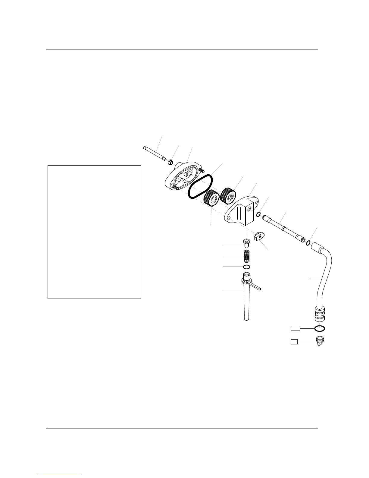
Carpigiani K 3 User’s guide
This manual is for the exclusive use of licensees and employees of McDonald’s Systems Inc Page 49 of 63
Version 5: October 2012
step 10
Insert the feeding tube (#271A) in the pump cover: push and turn it clockwise.
step 11
Lubricate the drive shaft (#96). Position drive shaft into the rear of mix hopper, pushing it towar ds the back
and rotating it slightly until it enters the drive hub. Hold the pu mp body assembly, with the blocking pin
hook on the right, keep your thumbs over the pump gears so that they remain in place, push and turn the
pump clockwise until the drive shaft mates with the driving gear. Now turn the pu mp cou nter clockwise until
it locks onto the blocking pin.
step 12
Assemble the pump cover (#202A) with the feeding tube downwards on to the pump body and turn the two
knobs (#8B) tightly
8B Hand screws
31 Check valve-slit
32A Pressure pipe
38 Driving gear
38A Driven gear
39A Pump body
96 Pump shaft
100 Shake chamber tube
202A Pump housing
206 Spring
207 Connection tube
271A Feeding tube
243 Seal-mix pump shaft
245 Pressure relief valve
1104 O-ring
1117 O-ring
1131 O-ring
1178 O-ring
1412 O-ring
1416 O-ring
202A
39A
38A
1178
1117
38
245
206A
1412
271A
207
1117
32A
1131
96
243
31
8B
Page 50
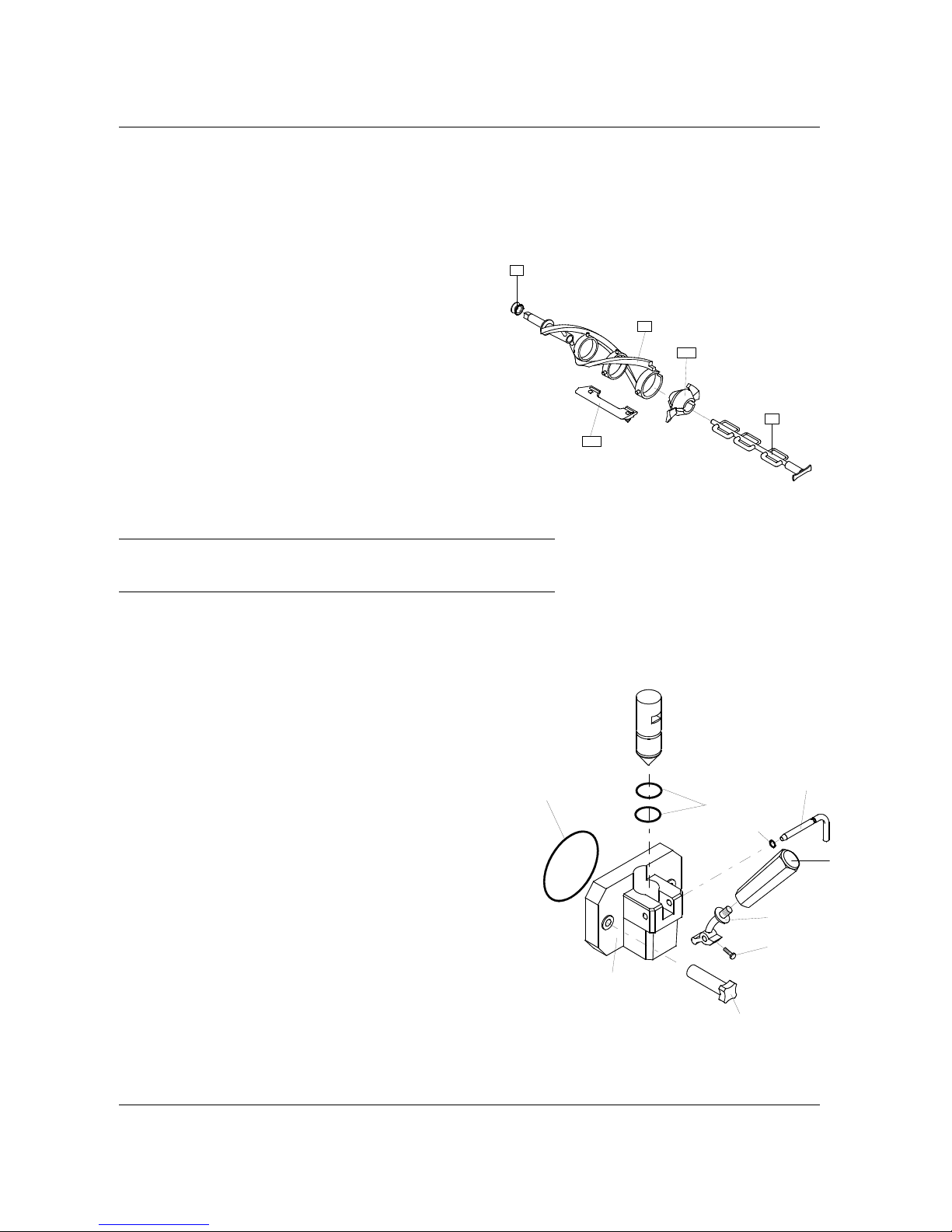
Carpigiani K 3 User’s guide
This manual is for the exclusive use of licensees and employees of McDonald’s Systems Inc Page 50 of 63
Version 5: October 2012
6.4.4 REASSEMBLY OF THE MIX HOPPER AGITATOR
step 1
Relocate the agitator back in its seat, pay attention to engage it onto its shaft correctly
6.5 REASSEMBLY OF WASHED AND SANITIZED COMPONENT PARTS
6.5.1 REASSEMBLY OF THE SUNDAE BEATER
step 1
Insert the 3 beater blades (#430) onto the beater
frame. Carpigiani suggests to replace the blades
each 6 months (please see the tune-up kit card).
step 2
Insert the end pusher (#25P) onto the beater frame.
step 3
Insert the end of the idler shaft (#24) in the rear
housing of the beater, through the end pusher. Push
the idler into position.
step 4
Lubricate the sides of the beater seal (#28) and
slide it onto the beater shaft.
IMPORTANT
Check the beater seal for integrity. Replace if worn or damaged.
It should be replaced rather frequently.
step 5
Insert the beater assembly into the cylinder. Push it while turning it clockwise until it engages in its rear
hub, otherwise the dispensing head cannot be fastened properly, mix can flow out and ser ious damage
may occur.
6.5.2 REASSEMBLY OF THE SUNDAE DISPENSING DOOR
step 1
Lubricate and slide the 2 piston O-ring (#1153) into
their seats.
step 2
Lubricate the piston (#30) and insert it, pointed
end down, in the dispensing head (#7) making
sure that the piston square notch lines up with the
rectangular opening on the spigot front.
step 3
Position the dispensing handle (#5) on the door
(#7) and insert the pivot pin (#6) in its housing
through the handle lever hole. Lubricate and slide
the O-ring (#1289) into its seat on the pivot pin.
Lubricate and slide into its seat the large
dispensing door O-ring (#1188).
step 4
Insert the dispensing door assembly onto the two front panel
studs and fasten it with the two knobs (#8) hand tight.
28
21
24
25P
430
1188
7
1289
214
43
5
6
1153
8
Page 51
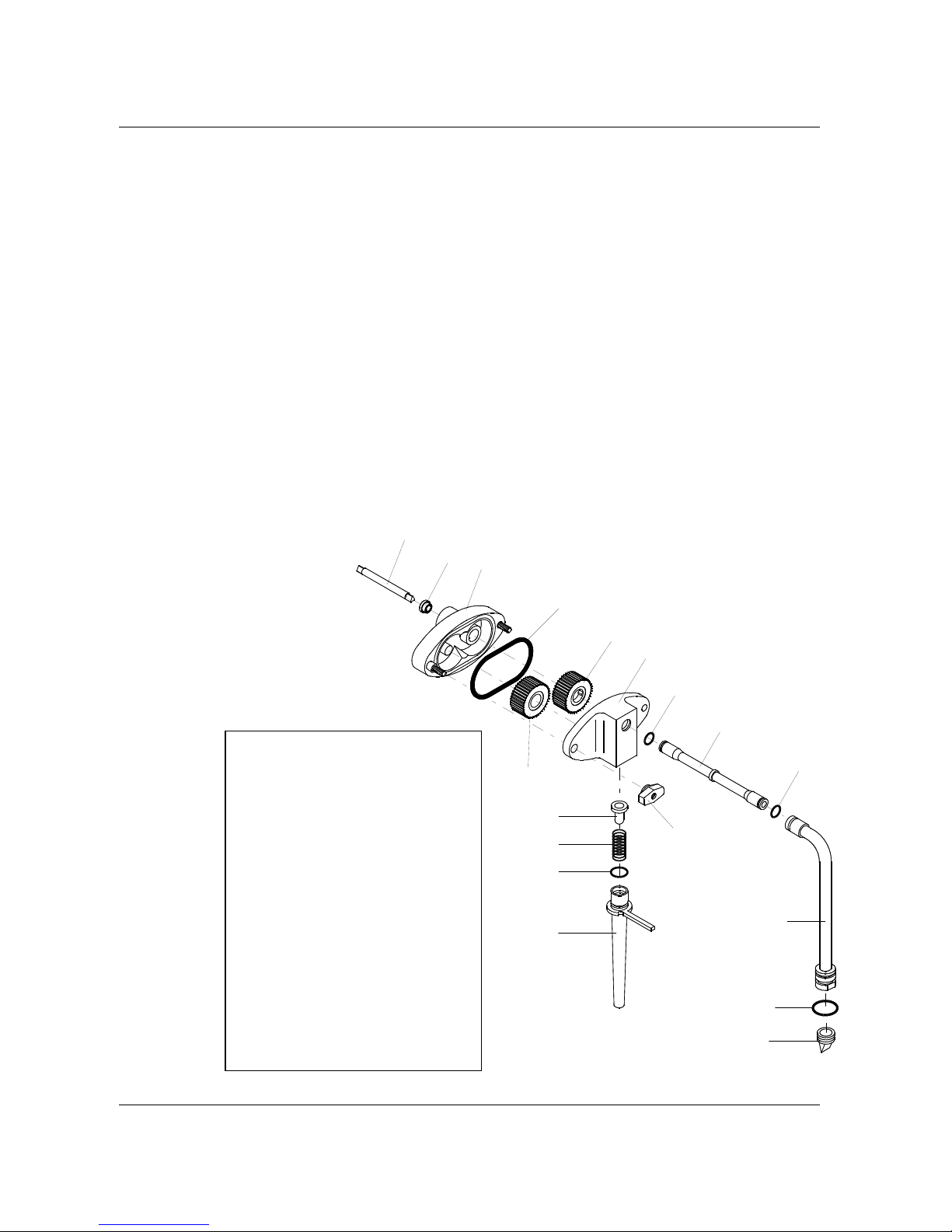
Carpigiani K 3 User’s guide
This manual is for the exclusive use of licensees and employees of McDonald’s Systems Inc Page 51 of 63
Version 5: October 2012
6.5.3 REASSEMBLING OF THE SUNDAE MIX PUMP
step 1
Lubricate and replace the two O-rings (#1117) on the connection tube (#207).
step 2
Lubricate and replace the O-ring (#1131) and the duck bill valve (#31) on the pressure pipe (#32).
step 3
Insert the connection tube assembly in the pressure pipe (#32).
step 4
Place the pressure pipe in a sanitizing solution.
step 5
Insert the pump gears (#38-#38A) into the pump body (#39).
step 6
Lubricate and replace the pump body O-ring (#1178).
step 7
Lubricate and replace the drive shaft seal (#243) into the pump body (#39).
step 8
Lubricate and replace the O-ring (#1412) on the feeding tube (#271).
step 9
Hold the pump cover (#202) upside down and insert the back flow valve (#245) and spring (#206) in their
pump cover housing.
step 10
Insert the feeding tube (#271) in the pump cover: push and turn it clockwise.
step 11
Lubricate the drive shaft (#96).
Position drive shaft into the rear of
mix hopper, pushing it towards the
back and rotating it slightly until it
enters the drive hub. Hold the
pump body assembly, with the
blocking pin hook on the right,
keep your thumbs over the pump
gears so that they remain in place,
push and turn the pump clockwise
until the drive shaft mates with the
driving gear. Now turn the pump
counter
clockwise until
it locks onto
the blocking
pin.
step 12
Assemble the
pump cover
(#202) with
the feeding
tube
downwards
onto the pump
body and turn
the two knobs
(#8B) tightly.
Pos. Description
8B Hand screws
31 Check valve-slit
32 Pressure pipe
38 Driven gear
38A Driving gear
40 Pump hosing – rear
96 Pump drive shaft
202 Pump hosing - front
206 Spring
208 Connection tube
243 Seal mix pump drive shaft
245 Pressure relief valve
272 Feeding tube
1117 O-ring
1178 O-ring
1412 O-ring
1416 O-ring
202
39
38A
1178
1117
38
245
206
1412
271
207
1117
1131
96
243
31
8B
32
Page 52
Carpigiani K 3 User’s guide
This manual is for the exclusive use of licensees and employees of McDonald’s Systems Inc Page 52 of 63
Version 5: October 2012
6.5.4 REASSEMBLING OF THE MIX TANK AGITATOR
step 1
Relocate the agitator back in its seat: pay attention to engage it onto its shaft correctly.
6.6 SANITIZING OF THE ENTIRE MACHINE
The machine must be sanitized before mix is poured in.
Carry out the following operations for both shake side and sundae side of the machine.
NOTE
After the machine’s brush cleaning, and more precisely from the moment you close th e front door (lid) of
the machine, it is necessary to run the machine in production (by pushing PROD. button) within 60
minutes. After the 60 minutes, the machine does not accept the PROD. button any more and it sets to
pasteurisation function automatically. In other words, you should make the “Sanitization of the whole
machine“ and the “Mix Priming“ within 60 minutes, then push PROD. button.
6.6.1 SANITIZE THE HOPPER
Fill the hopper to the maximum level with
McD Sanitizer prepared in water 70-90°F ( 21-32°C) [1
packet in 2-1/2 gal. (9-1/2 litres) of water = 100 PPM] and allow it to drain into the cylinder.
Using the brush, clean the mix level probes, the entire surface of the mix hopper, the surface of the
mix pump and the outside of the hopper agitator.
6.6.2 SANITIZE THE PUMP AND FREEZING CYLINDER
Press the push-button
and let the beater run for about 10 seconds. Press the p ush-button
“STOP”. The cylinder and the pump are now filled with the sanitizing solution.
Return to the machine with a small amount of McD sanitizer solution in a pail.
Dip the door spout brush in the pail of sanitizer and brush clean the dispensing spout. Repeat the
operation 2 times.
Wipe the exterior of machine with clean sanitized towel. Repeat the operation 2 times.
Wait for at least 5 minutes before proceeding with the next instructions.
6.6.3 DRAIN THE SANITIZER
Place an empty pail under the draw spout and pull the handle (for SUNDAE side).
Or press the “
” button (for the SHAKE side).
Allow all of the sanitizer to drain.
If the sanitizi ng solution does not flow out completely, keep the spigot open and press the
button, keep the beater running for 5 seconds so that the last solution residues flow out then push
STOP.
CAUTION
Do not keep the beater running for mo re than th e time strictly needed to complete washing and
sanitization. Without the lubrication of mix butterfat the beater blades wear out quickly.
Page 53
Carpigiani K 3 User’s guide
This manual is for the exclusive use of licensees and employees of McDonald’s Systems Inc Page 53 of 63
Version 5: October 2012
6.7 SYRUP SANITIZING, PRIMING AND CALIBRATION (SHAKE SIDE)
Make sure your hands are clean and sanitized before performing the following procedures.
Sanitizing the syrup lines:
a) Fill an empty pail with McD sanitizer prepared in water 122-140°F (50-60°C) [1 packet in 2-1/2
gallons (9-1/2 liters) of water = 100 PPM] (and mix the powder).
b) Place the pick up tubes inside. Push STOP button, then the corresponding “coloured cup” button
two times to run the syrup pump at maximum speed and let the sanitizing solution flow for 1
minute. Press STOP button to stop the syrup pump.
c) Repeat for all syrup lines.
Drain the sanitizer from the syrup lines
a) Remove the syrup pick up pipes from the pail and put them on a clean towel . Place an empty pail
under the draw spout and push STOP button, then press twice each “coloured cup” button to run
the syrup pumps and drai n the re s id ue s of s an itiz e r.
b) Push STOP button to stop the pump.
Priming the syrup lines with syrup:
a) Place each syrup pick up pipe in its syrup jug or connect the syrup connector to the syrup bag.
b) Place empty bucket under the spout.
c) Press the “coloured cup” button twice until th e syrup is dispensed, and then discard this portion of
syrup.
d) Press STOP button to stop the syrup pump.
e) Repeat for all syrup flavors.
f) Using a clean, sanitized towel, wipe the door cabinet.
WARNING
TO AVOID POTENTIAL BACTERIA GROWTH IN THE SYRUP SYSTEM DURING OPERATIONS,
ALL THE SYRUP LINES MUST ALWAYS BE FILLED WITH SYRUP
Calibrate syrups as follows:
Press “STOP” button, LED will light.
Place calibration cup under the spout.
Press “coloured cup” button to start the syrup pump and dispense syrup for 5 seconds (milk shake)
or 7 seconds (TTS). The pump will automatically stop. During the syrup dispensing, the display
indicates the “syrup number” and the speed of the pump.
Check syrup quantity; it should be 1 fluid ounce (30 ml), 1/8 ounce.
As soon as the piston closes and the syrup pump stops, the display blinks and shows the pump’s
speed. The
buttons flash for 3 seconds; acting upon those buttons we may increase
or decrease the pump’s speed. This adjustment becomes effective from the next time you push the
syrup buttons.
REPEAT THE CALIBRATION FOR EACH FLAVOUR.
Page 54
Carpigiani K 3 User’s guide
This manual is for the exclusive use of licensees and employees of McDonald’s Systems Inc Page 54 of 63
Version 5: October 2012
6.8 MIX PRIMING
Reminder
After the machine’s brush cleaning, and more precisely from the moment you close th e front door (lid) of
the machine, it is necessary to run the machine in production (by pushing PROD. button) within 60
minutes. After the 60 minutes, the machine does not accept the PROD. button any more and it sets to
pasteurisation function automatically. In other words, you should make the “Sanitization of the whole
machine“ and the “Mix Priming“ within 60 minutes, then push PROD. button.
Prime Hopper:
Retrieve 1 bag of McD shake or sundae mix from the walk-in refrigerator.
With the both sides of the machine in STOP mode, place an empty pail under the draw spouts.
Pull the handle (for SUNDAE sides) or press the
button (for the SHAKE side).
With the draw handle (SUNDAE side) or piston (SHAKE side) op en, pour one bag of mix into the
hoppers allowing it to drain into the freezing cylinders.
When only full strength mix (not mix and sanitizer) is flowing from the draw spouts, close the draw
handle (for SUNDAE side) or press the
button (for the SHAKE side).
Connect the mix pressure pipe:
When the mix stops bubbling from the bottom o f the hopper, take the mix pressure p ipe from the
sanitizing solution and insert it in its position in the bottom of the hopper. Make sure your hands
are clean and sanitized. Press the
button and let run the beater for only five seconds just to
check the pumps work well, the push STOP.
Turn the pressure pipe clockwise towards the pump and connect the tube to the pump.
Press PROD. button to start the Automatic freezing operation.
Replace the hopper cover.
Page 55
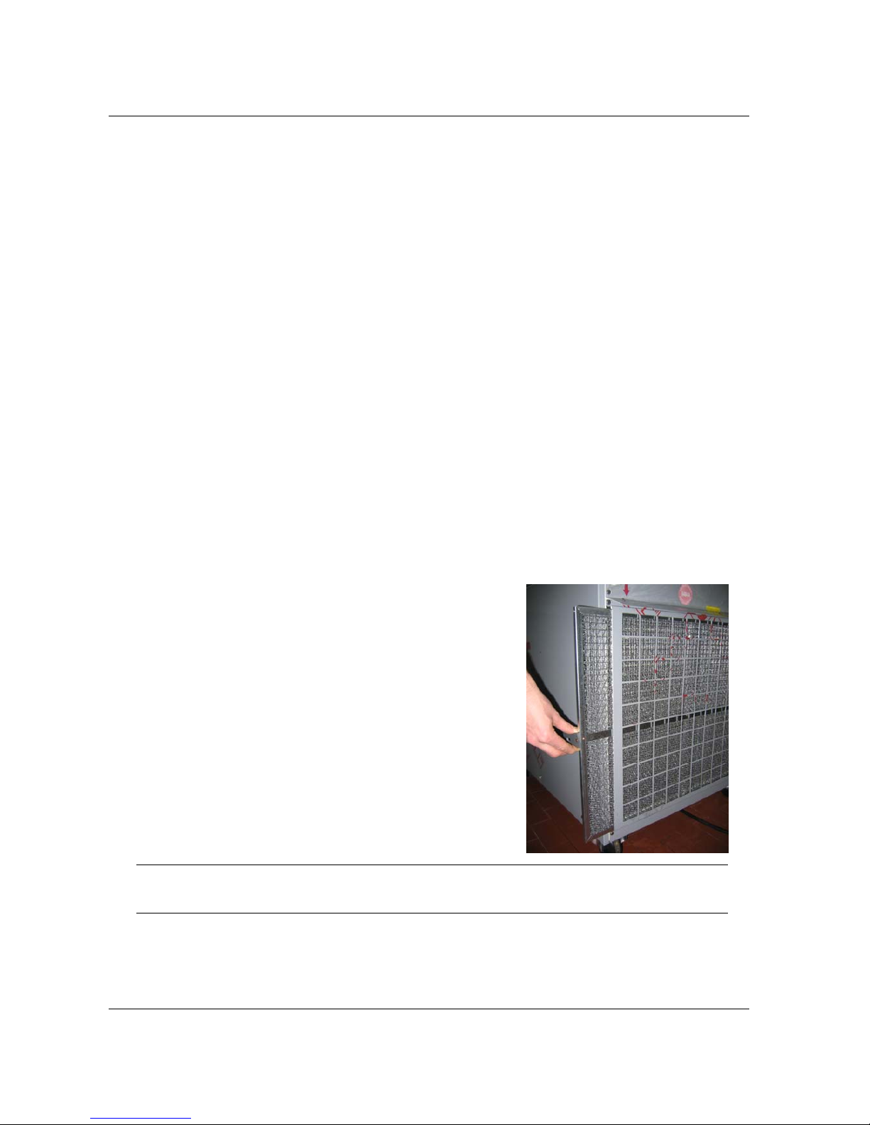
Carpigiani K 3 User’s guide
This manual is for the exclusive use of licensees and employees of McDonald’s Systems Inc Page 55 of 63
Version 5: October 2012
7. MONTHLY CLEANING
7.1 CLEAN MESH FILTERS (ONLY FOR AIR COOLED VERS ION)
It is necessary to clean the air filter every month, as follows:
step 1
Locate and remove the filter from the equipment (see fig.).
step 2
At the back sink, prepare a warm solution of McD All Purpose Super Concentrate (APSC) (HCS) using
the meter placed on the sink.
step 3
Wash the filter thoroughly in the warm McD All Purpose Super Concentrate (APSC) (HCS) solution.
step 4
After having washed the mesh filter, rinse it thoroughly using the hot water from the ho se at the back
sink.
NOTE: Flush in the opposite direction to normal air flow direction in the filter.
step 5
Shake all the water off the filter.
step 6
Using a clean, sanitized towel, wipe out any remaining moisture from the filter.
step 7
Place the filter into the filter’s track.
step 8
Push the filter in until it is seated.
step 9
Cleaning of the mesh filter is completed.
CAUTION
Never use sharp metal objects to execute this operation;
a regular operation of the freezing system mostly depends on condenser cleanout.
Page 56
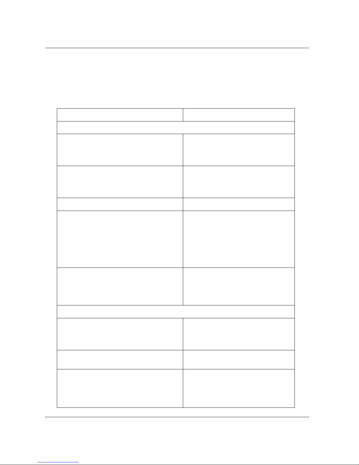
Carpigiani K 3 User’s guide
This manual is for the exclusive use of licensees and employees of McDonald’s Systems Inc Page 56 of 63
Version 5: October 2012
8. PREVENTATIVE MAINTENANCE
8.1 CHECK OUT LIST
During daily, weekly and fortnightly cleaning operations, check carefully the integrity of parts subject to
wear: if they appear worn, torn or not totally functional replace them. The manufacturer offers programmed
maintenance plans that include the periodical replacement of parts subject to wear.
CHECK SUGGESTED ACTION
SHAKE SIDE
PUMP
Integrity of O-ring and overflow valves.
Dry smoothness of gears in their seats.
If they show cuts, replace them.
If they do not turn well or turn too
freely, replace them or have them
checked by a technician.
DISPENSING DOOR
Check O-ring integrity, check smoothness of
piston.
Check syrup duck bill valves
Replace if they show damage.
Replace if they show damage
TANK MIXER
Check if it rotates freely.
Reassemble
CYLINDER BEATER
Check if beater idler and scraper blade show
dents and check their integrity.
Check integrity of beater seal (# 28).
Check that the wear on the bushing on the beater
idler is no more than 2 mm, as indicated by the
marking on the bushing itsel f. If ther e is more
than 2 mm wear, it is necessary to replace the
beater idler
Replace if broken or cracked.
Replace if damaged
Replace the idler
PERISTALTIC PUMP TUBE (# 385)
Check the integrity
The peristaltic pump tube should be
replaced at least once per year: in case
of heavy use, replacement is
suggested every 6 months.
Replacement is necessary in case of
inconsistence syrup delivery.
SUNDAE SIDE
PUMP
Integrity of O-ring and overflow valves.
Dry smoothness of gears in their seats.
If they show cuts, replace them.
If they do not turn well or turn too
freely, replace them or have them
checked by a technician.
DISPENSING LID
Check integrity of O-ring, check smoothness of
piston.
Replace if they show damage.
CYLINDER BEATER
Check if scraper blades show dents and crack.
Check if end-pusher and beater idler show
dents and check their integrity.
Check integrity of beater seal (# 28).
Replace if broken or cracked.
Replace if broken or cracked.
Replace if damaged
Page 57
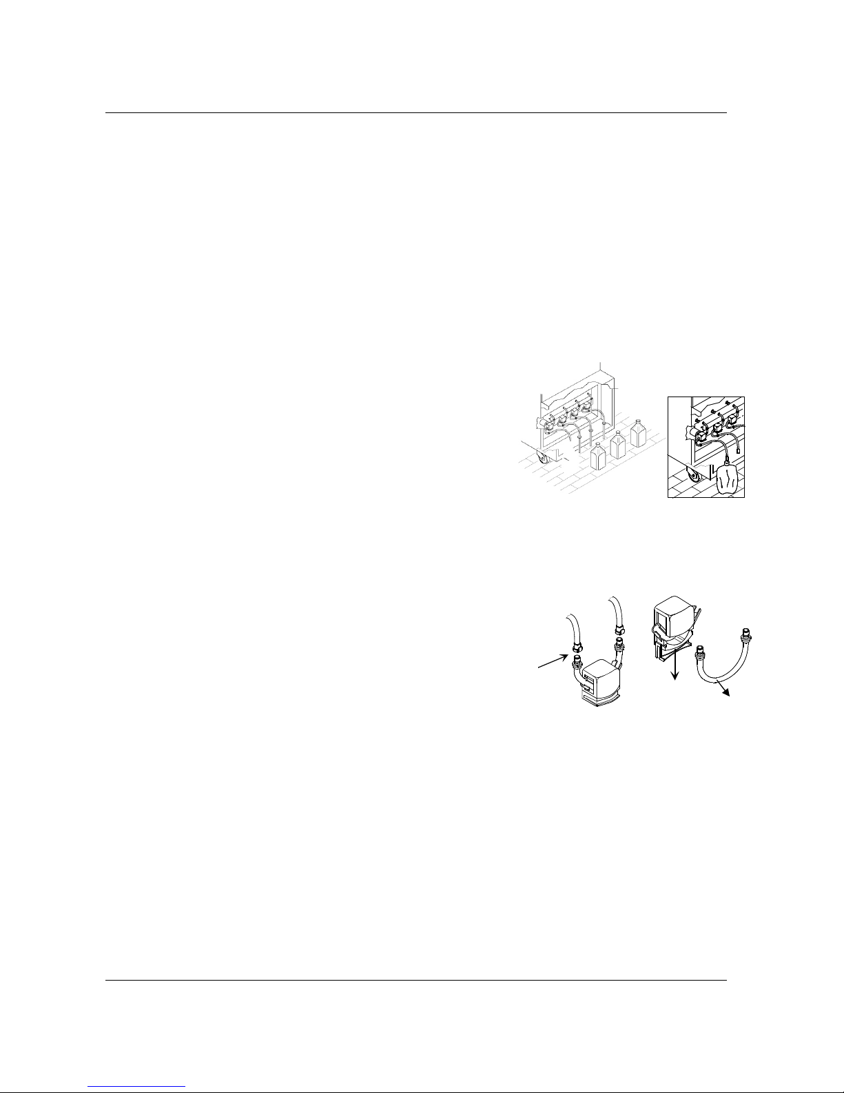
Carpigiani K 3 User’s guide
This manual is for the exclusive use of licensees and employees of McDonald’s Systems Inc Page 57 of 63
Version 5: October 2012
Rif. 1a
Rif. 2
385
8.2 PERIODICAL CHECK-UP AND MAINTENANCE
Replace the syrup pump hose (#385) every 12 months or needed, for example in case of heavy use,
replacement is suggested every 6 months. Replacement is necessary in case of inconsistent syrup
delivery.
Replace the mix pump gears (#38 and 38A) every 12 months.
Replace rubber parts (O-ring, beater seal) every 6 months.
Replace beater scraper blades (please refer to “tune-up kit” card).
Check the correct operation of syrup pumps (dispensed syrup quantity: 1 fl. Once in 5” for EU / in 7”
for USA)
8.2.1 PERISTALTIC PUMP TUBE REPLACEMENT INSTRUCTION
PUMP TUBE REMOVAL
step 1
Remove the syrup feed pipes or connectors from the syrup containers.
Wipe the outside of the pipes with a clean, sanitized towel.
step 2
Remove the syrup bags (jugs).
step 3
Place the syrup feed tubes into the pail contai ning McD All Purpose
Super Concentrate (APSC) (HCS) [1 packet in 2-1/2 gal. (9-1/2 litres)
of water = 100 PPM.] To avoid any contamination, cover the syrup containers with a plastic wrap.
step 4
Press STOP button. (LED On)
step 5
Press twice the “coloured cup” button to start the flow of McD All Pu rpose Super Concentrate (APSC)
(HCS) through the syrup line.
step 6
Allow the McD All Purpose Super Concentrate (APSC) (HCS) to flow until
all of the syrup is flushed out from the line.
step 7
Once the line is free of syrup, remove the syrup feed tube from the McD
All Purpose Super Concentrate (APSC) (HCS) and run the pump until the
syrup line is free from liquid.
step 8
Repeat steps 3 through 8 using McD Sanitizer (HCS) [1 packet in 2-1/2
gal. (9-1/2 liters) of water = 100 PPM].
step 9
Press the quick coupling connector (ref. 1a) to disconnect the syrup pickup tube from the pump tube.
step 10
Push on the quick coupling connector (ref. 1b) to disconnect the s yrup feed tube from the pump tube.
step 11
Open the pump by pushing downwards the hinged cover (ref. 2).
step 12
Grasp the pump tube (ref. 385) from one end, pull it up and pull out the second end, then remove
the pump tube.
Page 58

Carpigiani K 3 User’s guide
This manual is for the exclusive use of licensees and employees of McDonald’s Systems Inc Page 58 of 63
Version 5: October 2012
Pump Tube Installation
fase 1
Sanitize the new pumps tubes (ref.385) and lubricate the o-rings on the syrup line fittings.
fase 2
Place the pump tube into the pump body.
Fase 3
Pull up the pump cover to close it.
fase 4
Connect the syrup feed tube into the pump tube fitting.
fase 5
Connect the syrup pickup tube into the pump tube fitting.
fase 6
Replace the syrup jugs.
fase 7
Prime the syrup lines. Dispense one serving of syrup into a cup and discard this portion.
fase 8
Calibrate the syrup system according to the instructions in the equipment manual.
Page 59
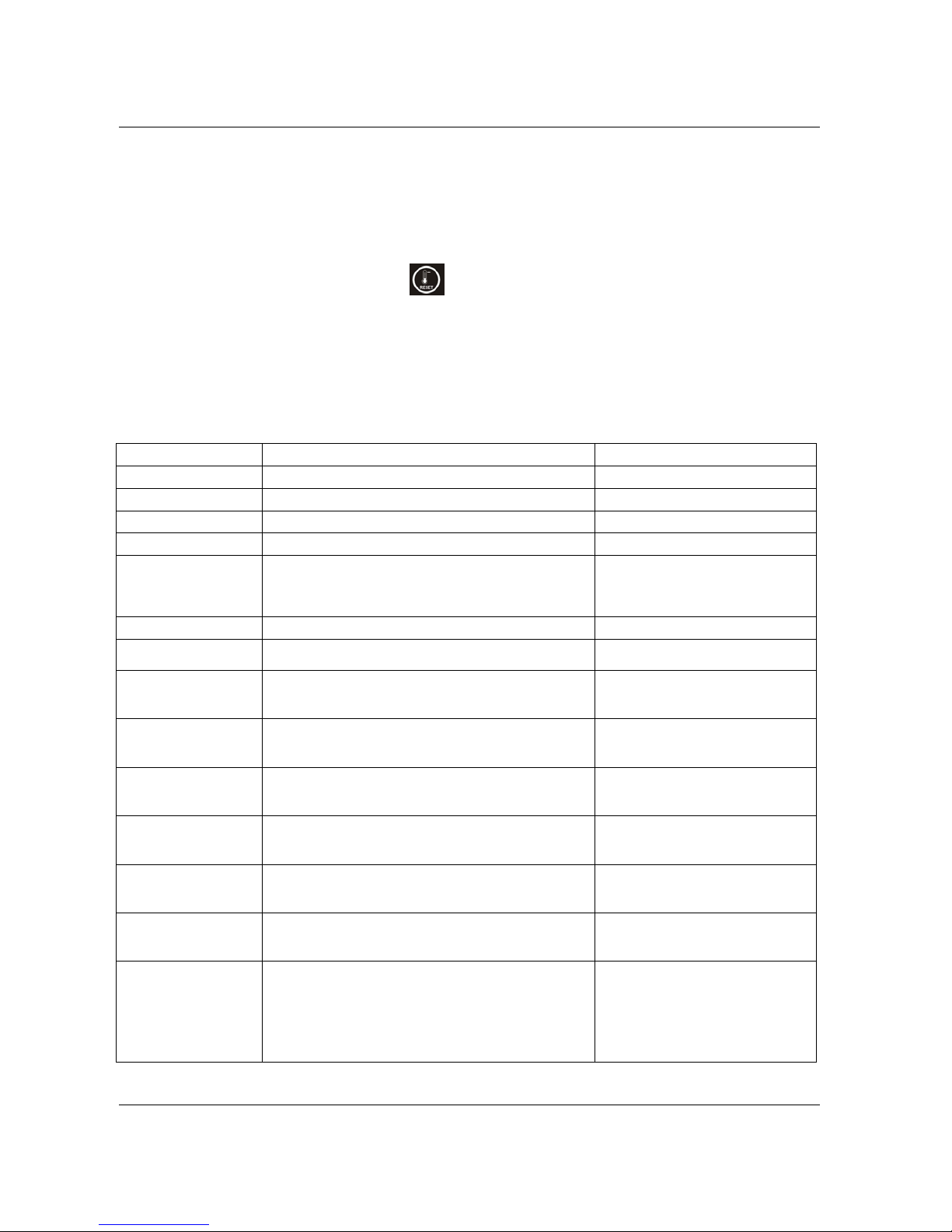
Carpigiani K 3 User’s guide
This manual is for the exclusive use of licensees and employees of McDonald’s Systems Inc Page 59 of 63
Version 5: October 2012
9. TROUBLESHOOTING
9.1 ALARMS
The machine issues possible alarm messages on the display and makes the writing blink.
In case of alarm which has reset, the writing will be on display in a fixed way (it will not blink).
To reset the writing, press Storage/Reset key
.
The machine can be used in ice cream production even if an alarm is active; if it is a critical alarm, the
machine will not allow you to select ice cream production program; should this be the case, press STOP
and do not use the machine till it is repaired.
Following find the alarm list:
DISPLAY DESCRIPTION CORRECTIVE ACTION
Add Mix
Mix level is lower than the medium level sensor
Pour the mix in the hopper
Mix Out
Mix level is lower than the low level sensor
Pour the mix in the hopper
Spigot Opened
The back spigot is opened or out of seat Close the pigot
Power on
A black out has occurred
Wash In n days
It indicates the days remaining for next cleaning; when “Wash
today!” appears the machine must be disassembled, cleaned and
sanitized. Press RESET button to reset the message on the
display.
Do Not Serve!
Product under process; please wait and don’t serve yet
No Topping Water
(Soft side only)
The Water in the topping bin is lower than the sensor level
Add water in the topping bin
Pasto needed!
The pasteurisation is not completed efficiently. run a pasteurization cycle until PASTO
END appears to unlock the machine.
Push STOP then PROD .
Why in STOP ??
If the machine is in Stop with the level covered, the blinking
message “Why in Stop” will be displayed after 30’ and the
acoustic intermittent alarm will be heard.
Set the machine in Production,
Pasteurisation or Storage.
Hopper Temp Warm
The timer activates in Production and Storage every 4 hours. If
the temperature remains over 4°C for too long, the following
message is displayed:
It may be cancelled by pressing the
Storage key. It’s an advise only.
Barrel Temp Warm
The timer activates in Production and Storage every 4 hours. If
the temperature remains over 4°C for too long, the following
message is displayed.
It may be cancelled by pressing the
Storage key. It’s an advise only.
Hopper Temp High
The timer activates in Production and Storage every 4 hours. If
the temperature remains over 4°C for too long, the following
message is displayed.
It may be cancelled by pressing the
Storage key. It’s an advise only.
Barrel Temp High
The timer activates in Production and Storage every 4 hours. If
the temperature remains over 4°C for too long, the following
message is displayed.
It may be cancelled by pressing the
Storage key. It’s an advise only.
WINK
(only machine with
Lonworks device)
When on the second line on the display soft side appears the
message “WINK”, it means that the restaurant manager checks
the correct connection of the machine to the computer network.
This message is displayed for a minute and it is accompanied
by a beep. At the end of the minute the display returns to
standard view.
Wait 1 minute
Page 60
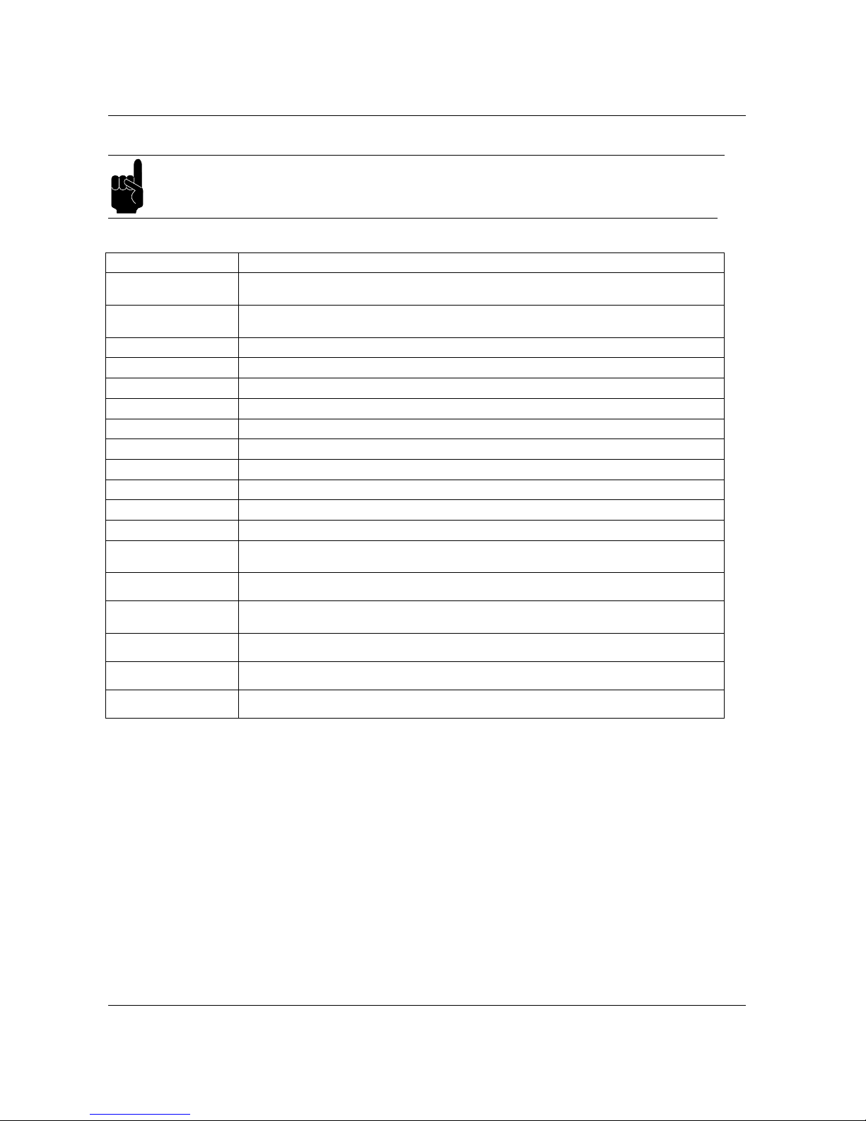
Carpigiani K 3 User’s guide
This manual is for the exclusive use of licensees and employees of McDonald’s Systems Inc Page 60 of 63
Version 5: October 2012
Following find the ALARM’S list:
WARNING
The technician’s intervention is necessary when the ALARM message occurs.
DISPLAY DESCRIPTION
Safety Therm. Cyl
The safety thermostat of the cylinder intervened. The machine passes to STOP and doesn’t complete
the pasteurisation cycle. The mix IS NOT pasteurised.
Safety Therm. Hop
The safety thermostat of the hopper intervened. The machine passes to STOP and doesn’t complete
the pasteurisation cycle. The mix IS NOT pasteurised.
Overload Beater
The thermal relay intervened upon the beater’s motor.
Pressure Switch
The pressure switch intervened.
Overload Compres
The thermal relay of the compressor’s motor intervened.
Al. Hopper Probe
The temperature probe of the hopper doesn’t work.
Al. Cylind. Probe
The temperature probe of the cylinder doesn’t work.
Al. IceHop. Probe
The sensor of the hopper’s vaporizer doesn’t work.
Al Evapor.Probe
The sensor of the cylinder’s vaporizer doesn’t work.
Ice Cylinder
This alarm may appear due to the scarce supply of the cylinder.
Timeout Prd.
Freezing problems, the product doesn’t harden.
Belt Alarm
The beater in the hopper doesn’t work.
Invert Phases!
It’s necessary to invert 2 phases in the three-phase supply line in order to make the beater’s rotation
direction correct.
Al. Topping Probe
(Soft side only)
The temperature topping probe doesn’t work.
Overload Mixer
(Shake side only)
The thermal relay of the mixer intervened. The machine doesn’t pass to Stop but displays the alarm that
remains on display only momentarily.
IMSA Open
(Shake side only)
Carter of the actuator’s cover is opened.
IMSB Open
(Shake side only)
The spinner’s cover is opened.
Level failure
(Shake side only)
Indicates the anomalous functioning of the cup’s level sensor.
Page 61
Carpigiani K 3 User’s guide
This manual is for the exclusive use of licensees and employees of McDonald’s Systems Inc Page 61 of 63
Version 5: October 2012
Page 62
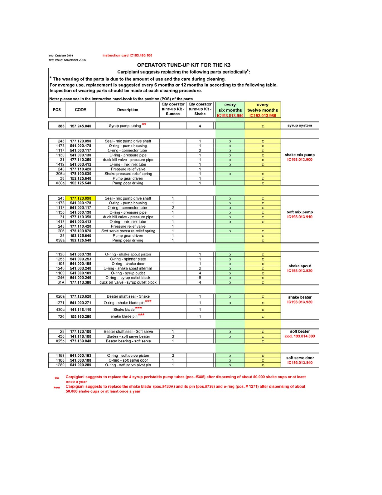
Carpigiani K 3 User’s guide
This manual is for the exclusive use of licensees and employees of McDonald’s Systems Inc Page 62 of 63
Version 5: October 2012
Page 63

Carpigiani K 3 User’s guide
This manual is for the exclusive use of licensees and employees of McDonald’s Systems Inc Page 63 of 63
Version 5: October 2012
®
 Loading...