

Carmelli NG1135F Assembly Instructions Manual

DRIFTWOOD 56" FOOSBALL TABLE
ASSEMBLY INSTRUCTIONS
Please Do Not Hesitate to
Contact Our Consumer Hotline
at
800-759-0977
with Any Questions That May
Arise During Assembly or
Use of This Product!
Ver. 0317
NG1135F

THANK YOU!
Thank you for purchasing this product. We work around the clock and around the globe to ensure
that our products maintain the highest possible quality. However, in the rare case of issues during
assembly or use of this product, please contact our Consumer Hotline at 800-759-0977 for immediate
assistance before contacting your retailer. Please read the warranty information at the back of these
assembly instructions for further details.
ASSEMBLY TIPS
IMPORTANT! PLEASE READ THESE ASSEMBLY INSTRUCTIONS
IN ENTIRETY BEFORE ASSEMBLING YOUR PRODUCT.
1. Find a clean, level surface to begin the assembly of your game table. We recommend that two adults
work together to assemble this game. You may want to carefully cut or tear the four corners of the box
so that the bottom of the box can be used as your work surface.
2. Remove all of the contents from box and verify that you have all of the parts shown on the Parts
List before you begin assembly. Note: Some parts may be pre-installed or pre-assembled.
3. Some figures or drawings may not look exactly like product.
4. When installing parts that have more than one screw or bolt, hand tighten all screws or bolts
in place before final tightening with screwdriver or wrench.
5. Electric screwdrivers may be helpful during assembly; however, please set a low torque and use
extreme caution because screws may be stripped or overtightened, resulting in damaged parts, if the
electric screwdriver’s torque is set too high.
WARNINGS!
READ AND FOLLOW ALL ASSEMBLY, OPERATION AND SAFETY INSTRUCTIONS CAREFULLY.
CHOKE HAZARD - THIS ITEM MAY CONTAIN SMALL BALLS AND PARTS
NOT SUITABLE FOR CHILDREN UNDER 3 YEARS OF AGE.
CARE AND USE
1. This product is intended for INDOOR use only.
2. Do NOT drag the table when moving it, as this will damage the legs.
2
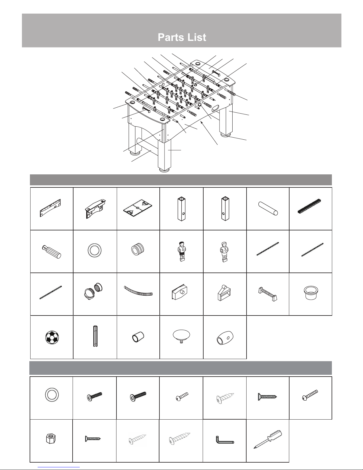
Parts List
DRIFTWOOD 56" FOOSBALL TABLE - NG1135F
38
34
2
20
For replacement parts
please call 800-759-0977.
26
25
24
22
21
23
19
32
31
3
4
27
1
35
36
5
7,28,29,30
37
6
PARTS
#1 NGP2756
SIDE PANEL
#19 NGP5972 #20 NGP5794 #21 NGP5795 #22 NGP5973 #23 NGP5974 #24 NGP5798
#2 NGP2757 #3 NGP5788 #4 NGP2758 #5 NGP2759 #6 NGP5971
X2
END PANEL
X2
PLAYFIELD
X1
LEG - LEFT
X2
LEG - RIGHT
X2
LEG BAR
Illustrations Not to Scale
#7 NGP5792
X2
PLAYFIELD
SUPPORT BRACE
X2
#25 NGP5799
X11
5 PLAYER ROD
#31 NGP5805
X2
MANUAL SCORER
X4
HAND GRIP
#26 NGP5800
2 PLAYER ROD
#34 NGP5807
SOCCER BALL
X8
X16
PLASTIC ROD
WASHER
RUBBER BUMPER
X16
AWAY PLAYER
#27 NGP5801 #28 NGP5802 #29 NGP5803
X2 X2 X2
2 PIECE BALL
LAUNCHER
BALL RUNNER
#35 NGP5808 #36 NGP5809 #37 NGP5810
X2 X4 X8
APRON CORNER
ROD END CAP
LEG LEVELER
SIDE BALL
CATCHER
X11
HOME PLAYER
#30 NGP5804
X2
BALL CATCHER
#38 NGP5976
X4
STOP RING
HARDWARE PACK - NGP5812
5/16”
X24
X26
5/16”x35mm
#16
#8 #9 #10 #11 #12 #13
FLAT WASHER
#15
X16 X8 X8
BOLT
5/16”x60mm
BOLT
X2 X4 X4
#17 #18 #33
5/8” BOLT
1/2” SCREW
X28
1” FLAT SCREW
ADDITIONAL EQUIPMENT
X1
REQUIRED:
X2
3 PLAYER ROD
#32 NGP58061
X2
SILVER METAL
CUP
X24
#14
1-1/8” BOLT
X4
X4
3/17
X26
LOCKNUT
1/2” FLAT SCREW
3/4” SCREW
1-3/4 SCREW
HEX WRENCH
PHILLIPS HEAD
3
SCREWDRIVER

ASSEMBLY INSTRUCTIONS
1. Place PLAYFIELD #3, with field markings facing down, onto the ledge of the SIDE PANELS #1.
Note: The table is assembled upside down.
#1
#3
2. Attach one END PANEL #2 to each end of the table with 1/4” BOLT #10 and 1/4” FLAT WASHER #8.
Note: DO NOT over tighten bolts. In this step, loosely tighten just until sides touch.
3. Attach PLAYFIELD to table with 1” FLAT SCREWS #13 around inside edge using pre-drill holes. Note: ALWAYS
use pre-drilled holes. If not, permanent damage can be done to table. A flashlight can be helpful in aligning holes.
It may be helpful to have a second person push on the opposite side, as you attach Playfield, in order to square
up surface. Make sure End Panels fit snuggly against Side Panels before screwing down Playfield.
4. Insert the APRON CORNERS #35 onto the SIDE PANELS #1 and END PANELS #2 on the four corners.
Note: Make sure inside screw holes are positioned at top.
5. Tighten 1/4” BOLTS #10, loosely tightened in Step 2, on both sides.
Field corners are
#35
Playfield
intentionally tapered
down for play.
#2
#8
#10
#13
Side
Panel
#1
#8
#10
4

ASSEMBLY INSTRUCTIONS (CONT.)
6. Position each PLAYFIELD SUPPORT BRACE #7 between the SIDE PANELS as shown below. Attach the
SUPPORT BRACE #7 with 1-3/4” SCREW #18. Attach the APRON CORNERS to each corner of the table
with 1/2” SCREW #12.
#12
#35
#7
#18
#18
7. Attach the SIDE BALL CATCHER #29 to each of the SIDE PANELS with 1/2” SCREW #12. Attach the
BALL CATCHER #30 to each of the END PANELS with 1/2” SCREW #12. Attach the BALL RUNNER #28
onto the SIDE BALL CATCHER and the BALL CATCHER openings as shown below.
#12
#30
#12
#29
#28
#28
5

ASSEMBLY INSTRUCTIONS (CONT.)
8. Insert LEG BAR #6 into both LEGS as shown. Attach LEFT LEG #4 and RIGHT LEG #5 to each corner of
the table with 5/16” BOLT #9 and 5/16” FLAT WASHER #8.
9. Thread one LEG LEVELER #37 onto each LEG. Carefully turn table over.
#6
#5
#4
#37
#8
#9
10. Begin PLAYER ROD assembly by partially inserting PLAYER ROD into the appropriate hole in the SIDE PANEL.
11. Before continuing, refer to the diagrams below for correct rod orientation and player placement. Note: You may
choose either color for home or visitor teams.
NOTE: Hole on end of rod indicates handle side.
#8
Hand tighten ALL bolts
before final tightening.
#9
6
 Loading...