

Canon MF7170i Service Manual. Parts Catalog

Service Manual
MF7200/7100 Series
MF7170i
Jan 30 2006

Application
This manual has been issued by Canon Inc. for qualified persons to learn technical theory, installation, maintenance, and repair
of products. This manual covers all localities where the products are sold. For this reason, there may be information in this
manual that does not apply to your locality.
Corrections
This manual may contain technical inaccuracies or typographical errors due to improvements or changes in products. When
changes occur in applicable products or in the contents of this manual, Canon will release technical information as the need
arises. In the event of major changes in the contents of this manual over a long or short period, Canon will issue a new edition
of this manual.
The following paragraph does not apply to any countries where such provisions are inconsistent with local law.
Trademarks
The product names and company names used in this manual are the registered trademarks of the individual companies.
Copyright
This manual is copyrighted with all rights reserved. Under the copyright laws, this manual may not be copied, reproduced or
translated into another language, in whole or in part, without the written consent of Canon Inc.
COPYRIGHT © 2001 CANON INC.
Printed in Japan
Caution
Use of this manual should be strictly supervised to avoid disclosure of confidential information.
Symbols Used
This documentation uses the following symbols to indicate special information:
Symbol Description
Indicates an item of a non-specific nature, possibly classified as Note, Caution, or Warning.
Indicates an item requiring care to avoid electric shocks.
Indicates an item requiring care to avoid combustion (fire).
Indicates an item prohibiting disassembly to avoid electric shocks or problems.
Indicates an item requiring disconnection of the power plug from the electric outlet.
Indicates an item intended to provide notes assisting the understanding of the topic in question.
Memo
Introduction
REF.
Indicates an item of reference assisting the understanding of the topic in question.
Provides a description of a service mode.
Provides a description of the nature of an error indication.

Introduction
The following rules apply throughout this Service Manual:
1. Each chapter contains sections explaining the purpose of specific functions and the relationship between electrical and mechanical systems with reference to the timing of operation.
In the diagrams, represents the path of mechanical drive; where a signal name accompanies the symbol , the arrow indicates the
direction of the electric signal.
The expression "turn on the power" means flipping on the power switch, closing the front door, and closing the delivery unit door, which results in
supplying the machine with power.
2. In the digital circuits, '1'is used to indicate that the voltage level of a given signal is "High", while '0' is used to indicate "Low".(The voltage value, however, differs from circuit to circuit.) In addition, the asterisk (*) as in "DRMD*" indicates that the DRMD signal goes on when '0'.
In practically all cases, the internal mechanisms of a microprocessor cannot be checked in the field. Therefore, the operations of the microprocessors
used in the machines are not discussed: they are explained in terms of from sensors to the input of the DC controller PCB and from the output of the
DC controller PCB to the loads.
The descriptions in this Service Manual are subject to change without notice for product improvement or other purposes, and major changes will be communicated in the form of Service Information bulletins.
All service persons are expected to have a good understanding of the contents of this Service Manual and all relevant Service Information bulletins and be
able to identify and isolate faults in the machine."

Contents
Contents
Chapter 1 Introduction
1.1 System Construction .................................................................................................................................. 1- 1
1.1.1 Pickup/ Delivery /Original Handling Accessories System Configuration (MF7170i) ................................................1- 1
1.1.2 Reader Heater/ Cassette Heater System Configuration (MF7170i) ........................................................................1- 1
1.1.3 Printing/Transmitting Accessories System Configuration (MF7170i) ......................................................................1- 2
1.1.4 Functions of the Printing/Transmission Functions (MF7170i) .................................................................................1- 3
1.2 Product Specifications ................................................................................................................................1- 4
1.2.1 Names of Parts........................................................................................................................................................1- 4
1.2.1.1 External View (MF7170i).......................................................................................................................................................... 1- 4
1.2.1.2 Cross-Section .......................................................................................................................................................................... 1- 4
1.2.2 Using the Machine...................................................................................................................................................1- 5
1.2.2.1 Turning On the Power Switch .................................................................................................................................................. 1- 5
1.2.2.2 When Turning Off the Main Power Switch ............................................................................................................................... 1- 5
1.2.2.3 Control Panel (MF7170i) .......................................................................................................................................................... 1- 7
1.2.3 User Mode Items .....................................................................................................................................................1- 7
1.2.3.1 Common Settings .................................................................................................................................................................... 1- 7
1.2.3.2 Timer Settings .......................................................................................................................................................................... 1- 8
1.2.3.3 Adjustment/Cleaning................................................................................................................................................................ 1- 8
1.2.3.4 Report Settings ........................................................................................................................................................................ 1- 8
1.2.3.5 System Settings ....................................................................................................................................................................... 1- 8
1.2.3.6 Copy Settings........................................................................................................................................................................... 1- 9
1.2.3.7 Communication Settings .......................................................................................................................................................... 1- 9
1.2.3.8 Printer Settings ...................................................................................................................................................................... 1- 10
1.2.3.9 Address Book Settings........................................................................................................................................................... 1- 11
1.2.3.10 Recommended setting of system management information ................................................................................................ 1- 11
1.2.3.11 The Reference Information of the Department ID Management .......................................................................................... 1- 11
1.2.4 Maintenance by the User.......................................................................................................................................1- 12
1.2.4.1 User Maintenance Items ........................................................................................................................................................ 1- 12
1.2.4.2 Cleaning ................................................................................................................................................................................. 1- 12
1.2.5 Safety ....................................................................................................................................................................1- 13
1.2.5.1 Safety of the Laser Light ........................................................................................................................................................ 1- 13
1.2.5.2 CDRH Regulations................................................................................................................................................................. 1- 13
1.2.5.3 Handling the Laser Unit ......................................................................................................................................................... 1- 14
1.2.5.4 Safety of Toner ...................................................................................................................................................................... 1- 14
1.2.5.5 Point to Note about Fire ......................................................................................................................................................... 1- 14
1.2.5.6 Cautions as to the replacement and disposal of lithium battery............................................................................................. 1- 14
1.2.5.7 Storing and Handling the Cartridge Before Unpacking .......................................................................................................... 1- 14
1.2.5.8 Storing or Handling the Cartridge After Unpacking ................................................................................................................ 1- 15
1.2.6 Product Specifications ...........................................................................................................................................1- 15
1.2.6.1 Product Specifications ........................................................................................................................................................... 1- 15
1.2.7 Function List ..........................................................................................................................................................1- 16
1.2.7.1 Printing Speed (MF7100 Series)............................................................................................................................................ 1- 16
1.2.7.2 Types of Paper....................................................................................................................................................................... 1- 18
Chapter 2 Installation
2.1 Making Pre-Checks .................................................................................................................................... 2- 1
2.1.1 Selecting the Site of Installation ..............................................................................................................................2- 1
2.1.2 Before Starting the Work .........................................................................................................................................2- 1
2.2 Unpacking and Installation .........................................................................................................................2- 4
2.2.1 Unpacking and Removing the Packaging Materials ................................................................................................2- 4
2.2.2 Installing the Toner Cartridge ..................................................................................................................................2- 4
2.2.3 Setting the Cassettes ..............................................................................................................................................2- 6

Contents
2.2.4 Connecting the Cable ..............................................................................................................................................2- 7
2.2.5 Checking the Image Quality.....................................................................................................................................2- 7
2.2.6 Setting the Country/Region......................................................................................................................................2- 8
2.2.7 Setting the Date and Time .......................................................................................................................................2- 8
2.2.8 Attaching Other Parts...............................................................................................................................................2- 8
2.3 Checking the Connection to the Network ................................................................................................... 2- 9
2.3.1 Checking the Network Connection...........................................................................................................................2- 9
2.4 Flow of Accessory Installation .................................................................................................................. 2- 10
2.4.1 Flow of Accessary Installation................................................................................................................................2- 10
2.5 Installing the Card Reader........................................................................................................................ 2- 11
2.5.1 Points to Note ........................................................................................................................................................2- 11
2.5.2 Checking the Contents...........................................................................................................................................2- 11
2.5.3 Installation Procedure ............................................................................................................................................2- 12
2.5.4 Registering the Card IDs........................................................................................................................................2- 17
2.6 Installing the Heater PCB ......................................................................................................................... 2- 18
2.6.1 Preparing the parts ................................................................................................................................................2- 18
2.6.2 Preparing the Host Machine ..................................................................................................................................2- 18
2.6.3 Installing the Heater PCB.......................................................................................................................................2- 20
2.7 Installing the Reader Heater..................................................................................................................... 2- 23
2.7.1 Preparing the parts ................................................................................................................................................2- 23
2.7.2 Installing the Reader Heater Harness....................................................................................................................2- 23
2.7.3 Removing Reader Components.............................................................................................................................2- 27
2.7.4 Removing Parts at the Left of the Reader..............................................................................................................2- 28
2.7.5 Installing the Reader Heater ..................................................................................................................................2- 30
2.8 Installing the Cassette Heater .................................................................................................................. 2- 33
2.8.1 Preparing the parts ................................................................................................................................................2- 33
2.8.2 Preparing the Host Machine ..................................................................................................................................2- 33
2.8.3 Installing the Cassette Heater................................................................................................................................2- 33
Chapter 3 Main Controller
3.1 Overview/Configuration .............................................................................................................................. 3- 1
3.1.1 Construction and Mechanisms.................................................................................................................................3- 1
3.2 Outline of the Electrical Circuitry ................................................................................................................ 3- 1
3.2.1 Image Processor PCB .............................................................................................................................................3- 1
3.3 Image Processing....................................................................................................................................... 3- 2
3.3.1 Overview of the Image Flow ....................................................................................................................................3- 2
3.3.2 Construction of the Image Processing Module ........................................................................................................3- 3
3.3.3 Reader Unit Input Image Processing.......................................................................................................................3- 3
3.3.4 Compression/ Extesion/ Editing Block ....................................................................................................................3- 4
3.3.5 Printer unit Output Image Processing......................................................................................................................3- 4
3.4 Image Data Flow ........................................................................................................................................ 3- 5
3.4.1 Flow of Image Data According to Copy Functions...................................................................................................3- 5
3.4.2 Flow of Image Data for the SEND Function.............................................................................................................3- 5
3.4.3 Flow of Image Data for the Fax Transmission .........................................................................................................3- 6
3.4.4 Flow of Image Data for the Fax Reception Function................................................................................................3- 6
3.4.5 Flow of Image Data for the PDL Function................................................................................................................3- 7
3.5 Parts Replacement Procedure ................................................................................................................... 3- 8
3.5.1 Main Controller PCB ................................................................................................................................................3- 8
3.5.1.1 Removing the Rear Cover ....................................................................................................................................................... 3- 8
3.5.1.2 Removing the Left Cover (Rear) .............................................................................................................................................. 3- 8
3.5.1.3 Removing the RAM Cover ....................................................................................................................................................... 3- 8
3.5.1.4 Removing the SDRAM ............................................................................................................................................................. 3- 8
3.5.1.5 Removing the LAN Cover ........................................................................................................................................................ 3- 8
3.5.1.6 Removing the IP Cover............................................................................................................................................................ 3- 8
3.5.1.7 Removing the Image Processor PCB ...................................................................................................................................... 3- 9

Contents
3.5.1.8 Procedure after Replacing the Image Processor PCB ............................................................................................................ 3- 9
3.5.2 SDRAM..................................................................................................................................................................3- 10
3.5.2.1 Removing the Rear Cover ..................................................................................................................................................... 3- 10
3.5.2.2 Removing the RAM Cover ..................................................................................................................................................... 3- 10
3.5.2.3 Removing the SDRAM ........................................................................................................................................................... 3- 10
Chapter 4 Original Exposure System
4.1 Basic Constraction......................................................................................................................................4- 1
4.1.1 Specifications, Control Methods, and Functions .....................................................................................................4- 1
4.1.2 Major Components ..................................................................................................................................................4- 1
4.1.3 Control System Configuration..................................................................................................................................4- 2
4.1.4 Reader Controller PCB............................................................................................................................................4- 2
4.2 Basic Sequence..........................................................................................................................................4- 3
4.2.1 Basic Sequence at Power-on ..................................................................................................................................4- 3
4.2.2 Basic Sequence after Depression of Start Key (Book mode, One Sheet of original) ..............................................4- 3
4.2.3 Basic Sequence after Depression of Start Key (ADF Mode, One Sheet of Original) ..............................................4- 4
4.3 Various Control ...........................................................................................................................................4- 4
4.3.1 Controlling the Scanner Drive System.....................................................................................................................4- 4
4.3.1.1 Outline...................................................................................................................................................................................... 4- 4
4.3.1.2 Reader Motor Control .............................................................................................................................................................. 4- 5
4.3.2 Contact Image Sensor (CIS) ...................................................................................................................................4- 6
4.3.2.1 Outline...................................................................................................................................................................................... 4- 6
4.3.2.2 Analog Control Performed by the CIS...................................................................................................................................... 4- 7
4.3.3 Enlargement/Reduction ...........................................................................................................................................4- 7
4.3.3.1 Magnification Change in Vertical Scan Direction ..................................................................................................................... 4- 7
4.3.3.2 Magnification Change in Vertical Scan Direction ..................................................................................................................... 4- 7
4.3.4 Dirt Sensor Control ..................................................................................................................................................4- 7
4.3.4.1 Outline...................................................................................................................................................................................... 4- 7
4.3.5 Image Processing....................................................................................................................................................4- 9
4.3.5.1 Outline...................................................................................................................................................................................... 4- 9
4.3.5.2 CMOS Sensor Drive .............................................................................................................................................................. 4- 10
4.3.5.3 CMOS Sensor Output Gain Correction and Offset Correction............................................................................................... 4- 10
4.3.5.4 CMOS Sensor Output A/D Conversion .................................................................................................................................. 4- 10
4.3.5.5 Shading Correction (Outline) ................................................................................................................................................ 4- 10
4.3.5.6 Shading Adjustment ............................................................................................................................................................... 4- 10
4.3.5.7 Shading Correction ................................................................................................................................................................ 4- 10
4.4 Parts Replacement Procedure .................................................................................................................4- 12
4.4.1 Copyboard Glass...................................................................................................................................................4- 12
4.4.1.1 Removing the Copyboard Glass ............................................................................................................................................ 4- 12
4.4.1.2 Procedure after Replacing the Copyboard Glass .................................................................................................................. 4- 12
4.4.1.3 Removing the ADF Reading Glass ........................................................................................................................................ 4- 12
4.4.2 Reader Controller PCB..........................................................................................................................................4- 12
4.4.2.1 Removing the Rear Cover ..................................................................................................................................................... 4- 12
4.4.2.2 Removing the Right Cover (Lower)........................................................................................................................................ 4- 13
4.4.2.3 Removing the Right Cover (Upper)........................................................................................................................................ 4- 13
4.4.2.4 Removing the Left Cover (Rear) ............................................................................................................................................ 4- 13
4.4.2.5 Removing the Reader Rear Cover......................................................................................................................................... 4- 13
4.4.2.6 Removing the Copyboard glass ............................................................................................................................................. 4- 13
4.4.2.7 Removing the Reader Controller PCB ................................................................................................................................... 4- 14
4.4.3 Reader Motor.........................................................................................................................................................4- 15
4.4.3.1 Removing the Rear Cover ..................................................................................................................................................... 4- 15
4.4.3.2 Removing the Right Cover (Lower)........................................................................................................................................ 4- 15
4.4.3.3 Removing the Right Cover (Upper)........................................................................................................................................ 4- 15
4.4.3.4 Removing the Left Cover (Rear) ............................................................................................................................................ 4- 15
4.4.3.5 Removing the Reader Rear Cover......................................................................................................................................... 4- 16
4.4.3.6 Removing the Reader Motor .................................................................................................................................................. 4- 16
4.4.4 Contact Sensor......................................................................................................................................................4- 16
4.4.4.1 Removing the Rear Cover ..................................................................................................................................................... 4- 16

Contents
4.4.4.2 Removing the Right Cover (Lower)........................................................................................................................................ 4- 16
4.4.4.3 Removing the Right Cover (Upper)........................................................................................................................................ 4- 16
4.4.4.4 Removing the Left Cover (Rear) ............................................................................................................................................ 4- 17
4.4.4.5 Removing the Reader Rear Cover......................................................................................................................................... 4- 17
4.4.4.6 Removing the Copyboard Glass ............................................................................................................................................ 4- 17
4.4.4.7 Removing the Contact Image Sensor (CIS)........................................................................................................................... 4- 18
4.4.4.8 Procedure after Replacing the CIS ........................................................................................................................................ 4- 18
4.4.5 Copyboard Cover Open/Close Sensor ..................................................................................................................4- 18
4.4.5.1 Removing the Rear Cover ..................................................................................................................................................... 4- 18
4.4.5.2 Removing the Right Cover (Lower)........................................................................................................................................ 4- 18
4.4.5.3 Removing the Right Cover (Upper)........................................................................................................................................ 4- 18
4.4.5.4 Removing the Left Cover (Rear) ............................................................................................................................................ 4- 18
4.4.5.5 Removing the Reader Rear Cover......................................................................................................................................... 4- 19
4.4.5.6 Removing the Copyboard Cover Open/Close Sensor (Front/Rear) ....................................................................................... 4- 19
4.4.6 Contact Sensor HP Sensor....................................................................................................................................4- 19
4.4.6.1 Removing the Copyboard Glass ............................................................................................................................................ 4- 19
4.4.6.2 Removing the ADF Reading Glass ........................................................................................................................................ 4- 20
4.4.6.3 Removing the Contact Sensor HP Sensor............................................................................................................................. 4- 20
4.4.7 Reader Heater (option) ..........................................................................................................................................4- 20
4.4.7.1 Removing the Copyboard Glass ............................................................................................................................................ 4- 20
4.4.7.2 Removing the Reader Heater (Right) .................................................................................................................................... 4- 21
4.4.7.3 Removing the Reader Front Cover ........................................................................................................................................ 4- 21
4.4.7.4 Removing the ADF Reading Glass ........................................................................................................................................ 4- 21
4.4.7.5 Removing the Reader Heater (Left) ....................................................................................................................................... 4- 22
Chapter 5 Laser Exposure
5.1 Overview/Configuration .............................................................................................................................. 5- 1
5.1.1 Overview..................................................................................................................................................................5- 1
5.1.2 Specifications and Control Mechanism....................................................................................................................5- 1
5.1.3 Main Components....................................................................................................................................................5- 1
5.1.4 Control System Configuration..................................................................................................................................5- 1
5.2 Controlling the Laser Activation Timing ...................................................................................................... 5- 2
5.2.1 Laser Emission ON/OFF Control .............................................................................................................................5- 2
5.2.2 Horizontal Synchronization Control..........................................................................................................................5- 2
5.3 Controlling the Intensity of Laser Light ....................................................................................................... 5- 3
5.3.1 Automatic Photocurrent Control (APC)....................................................................................................................5- 3
5.4 Controlling the Laser Scanner Motor.......................................................................................................... 5- 3
5.4.1 Laser Scanner Motor Control...................................................................................................................................5- 3
5.5 Controlling the Laser Shutter...................................................................................................................... 5- 3
5.5.1 Laser Shutter Control...............................................................................................................................................5- 3
5.6 Parts Replacement Procedure ................................................................................................................... 5- 5
5.6.1 Laser/Scanner Unit ..................................................................................................................................................5- 5
5.6.1.1 Removing the Rear Cover ....................................................................................................................................................... 5- 5
5.6.1.2 Removing the Right Cover (Lower).......................................................................................................................................... 5- 5
5.6.1.3 Removing the Delivery Tray..................................................................................................................................................... 5- 5
5.6.1.4 Removing the Laser Scanner Unit ........................................................................................................................................... 5- 5
Chapter 6 Image Formation
6.1 Overview/Configuration .............................................................................................................................. 6- 1
6.1.1 Specifications of Image Formation System..............................................................................................................6- 1
6.1.2 Major Components of Image Formation System .....................................................................................................6- 1
6.2 Image Formation Process .......................................................................................................................... 6- 1
6.2.1 Image Formation Process........................................................................................................................................6- 1
6.3 Basic Sequence ......................................................................................................................................... 6- 2
6.3.1 Basic Sequence of Operation ..................................................................................................................................6- 2
6.4 Driving and Controlling the High-Voltage System ...................................................................................... 6- 3

Contents
6.4.1 Outline .....................................................................................................................................................................6- 3
6.4.2 Primary Charging Bias Control ................................................................................................................................6- 4
6.4.3 Developing Bias Control ..........................................................................................................................................6- 4
6.5 Secondary Transfer Mechanism................................................................................................................. 6- 5
6.5.1 Outline .....................................................................................................................................................................6- 5
6.5.2 Transfer Roller Bias Control ....................................................................................................................................6- 5
6.5.3 Static Eliminator Bias Control..................................................................................................................................6- 6
6.6 Parts Replacement Procedure ...................................................................................................................6- 7
6.6.1 Transfer Charging Roller .........................................................................................................................................6- 7
6.6.1.1 Removing the Transfer Charging Roller .................................................................................................................................. 6- 7
Chapter 7 Pickup and Feed System
7.1 Overview/Configuration .............................................................................................................................. 7- 1
7.1.1 Specifications/Configuration/Operation Methods ....................................................................................................7- 1
7.1.2 Locations of Main Units ...........................................................................................................................................7- 1
7.1.3 Roller Layout Drawing ............................................................................................................................................. 7- 1
7.1.4 Paper Path Drawing(Printer on its own) ..................................................................................................................7- 2
7.1.5 Paper Path Drawing(Finisher-U1) ...........................................................................................................................7- 3
7.1.6 Paper Path Drawing(Duplex Unit-A1/Finisher-U1) ..................................................................................................7- 3
7.1.7 Paper Path Drawing(Duplex-A1) .............................................................................................................................7- 4
7.1.8 Paper Path Drawing(Duplex-A1/Inner 2Way Tray-E1) ............................................................................................7- 4
7.1.9 Paper Path Drawing(Inner 2Way Tray-E1)..............................................................................................................7- 5
7.1.10 Sensor Layout Drawing .........................................................................................................................................7- 5
7.2 Detection Jams ...........................................................................................................................................7- 6
7.2.1 Delay Jams..............................................................................................................................................................7- 6
7.2.1.1 Delay Jam in Pickup Assembly ................................................................................................................................................ 7- 6
7.2.1.2 Delay Jam in Delivery Assembly (Paper Leading Edge Jam at First Delivery Sensor/Wound Paper Jam at Fixing Assembly) 7-
6
7.2.2 Stationary Jams.......................................................................................................................................................7- 6
7.2.2.1 Stationary Jam in Pickup Assembly ......................................................................................................................................... 7- 6
7.2.2.2 Stationary Jam in Delivery Assembly (Paper Trailing Edge Stationary Jam at First Delivery Sensor/Stationary Jam at Delivery
Sensor)........................................................................................................................................................................................... 7- 6
7.2.3 Other Jams ..............................................................................................................................................................7- 6
7.2.3.1 Door Open Jam........................................................................................................................................................................ 7- 6
7.3 Cassette Pickup Unit .................................................................................................................................. 7- 6
7.3.1 Overview..................................................................................................................................................................7- 6
7.3.2 Cassette Pickup Operation......................................................................................................................................7- 7
7.3.3 Cassette Paper Size Detection................................................................................................................................7- 8
7.4 Manual Feed Pickup Unit ...........................................................................................................................7- 8
7.4.1 Overview..................................................................................................................................................................7- 8
7.4.2 Post-pickup Control after Multi Manual Feed Pickup...............................................................................................7- 9
7.5 Parts Replacement Procedure .................................................................................................................7- 10
7.5.1 Cassette Pickup Assembly ....................................................................................................................................7- 10
7.5.1.1 Removing the Lower-left Cover ............................................................................................................................................. 7- 10
7.5.1.2 Removing the Cassette Pickup Assembly ............................................................................................................................. 7- 10
7.5.2 Cassette Pickup Roller ..........................................................................................................................................7- 10
7.5.2.1 Removing the Cassette Paper Pickup Roller ......................................................................................................................... 7- 10
7.5.3 Cassette Paper Sensor .........................................................................................................................................7- 10
7.5.3.1 Removing the Lower-left Cover ............................................................................................................................................. 7- 10
7.5.3.2 Removing the Cassette Pickup Assembly ............................................................................................................................. 7- 10
7.5.3.3 Removing the Cassette Paper Presence/Absence Sensor ................................................................................................... 7- 11
7.5.4 Cassette Size Sensor ............................................................................................................................................7- 11
7.5.4.1 Removing the Paper Size Detection Switches....................................................................................................................... 7- 11
7.5.5 Cassette Retry Paper Sensor................................................................................................................................7- 11
7.5.5.1 Removing the Lower-left Cover ............................................................................................................................................. 7- 11
7.5.5.2 Removing the Cassette Pickup Assembly ............................................................................................................................. 7- 11

Contents
7.5.5.3 Removing the Retry Sensor ................................................................................................................................................... 7- 12
7.5.6 Cassette Pickup Solenoid......................................................................................................................................7- 12
7.5.6.1 Removing the Lower-left Cover ............................................................................................................................................. 7- 12
7.5.6.2 Removing the Cassette Pickup Assembly ............................................................................................................................. 7- 12
7.5.6.3 Removing the Cassette Pickup Solenoid ............................................................................................................................... 7- 12
7.5.7 Separation Roller ...................................................................................................................................................7- 12
7.5.7.1 Removing the Feed and Separation Rollers .......................................................................................................................... 7- 12
7.5.8 Manual Pickup Roller.............................................................................................................................................7- 13
7.5.8.1 Removing the Toner Cartridge............................................................................................................................................... 7- 13
7.5.8.2 Removing the Transfer Registration Unit ............................................................................................................................... 7- 13
7.5.8.3 Removing the Feed Guide ..................................................................................................................................................... 7- 13
7.5.8.4 Removing the Multifeeder Pickup Roller ................................................................................................................................ 7- 13
7.5.9 Manual Feed Tray Paper Sensor...........................................................................................................................7- 14
7.5.9.1 Removing the Toner Cartridge............................................................................................................................................... 7- 14
7.5.9.2 Removing the Transfer Registration Unit ............................................................................................................................... 7- 14
7.5.9.3 Removing the Feed Guide ..................................................................................................................................................... 7- 14
7.5.9.4 Removing the Multifeeder Paper Presence/Absence Sensor ................................................................................................ 7- 14
7.5.10 Manual Pickup Solenoid.......................................................................................................................................7- 14
7.5.10.1 Removing the Toner Cartridge............................................................................................................................................. 7- 14
7.5.10.2 Removing the Transfer Registration Unit ............................................................................................................................. 7- 15
7.5.10.3 Removing the Feed Guide ................................................................................................................................................... 7- 15
7.5.10.4 Removing the Multifeeder Connector Cover ........................................................................................................................ 7- 15
7.5.10.5 Removing the Multifeeder Unit............................................................................................................................................. 7- 15
7.5.10.6 Removing the Multifeeder Pickup Solenoid ......................................................................................................................... 7- 15
7.5.11 Registration Roller................................................................................................................................................7- 16
7.5.11.1 Removing the Toner Cartridge............................................................................................................................................. 7- 16
7.5.11.2 Removing the Registration Roller ........................................................................................................................................ 7- 16
7.5.12 Registration Clutch...............................................................................................................................................7- 16
7.5.12.1 Removing the Rear Cover.................................................................................................................................................... 7- 16
7.5.12.2 Removing the Registration Clutch........................................................................................................................................ 7- 16
7.5.13 Separation Pad ....................................................................................................................................................7- 17
7.5.13.1 Removing the Toner Cartridge............................................................................................................................................. 7- 17
7.5.13.2 Removing the Transfer Registration Unit ............................................................................................................................. 7- 17
7.5.13.3 Removing the Feed Guide ................................................................................................................................................... 7- 17
7.5.13.4 Removing the Multifeeder Pickup Roller .............................................................................................................................. 7- 17
7.5.13.5 Removing the Separation Pad ............................................................................................................................................. 7- 18
Chapter 8 Fixing System
8.1 Overview/Configuration .............................................................................................................................. 8- 1
8.1.1 Specifications, Control Mechanisms, and Functions ...............................................................................................8- 1
8.1.2 Major Components...................................................................................................................................................8- 1
8.2 Various Control Mechanisms ..................................................................................................................... 8- 2
8.2.1 Controlling the Speed of the Fixing Film ..................................................................................................................8- 2
8.2.1.1 Controlling the Fixing Film Speed ............................................................................................................................................ 8- 2
8.2.2 Controlling the Fixing Film Temperature..................................................................................................................8- 2
8.2.2.1 Outline...................................................................................................................................................................................... 8- 2
8.2.2.2 Controlling the Fixing Film Temperature .................................................................................................................................. 8- 2
8.2.2.3 Target Temperatures by Mode ................................................................................................................................................ 8- 2
8.2.3 Detecting the Passage Paper ..................................................................................................................................8- 3
8.2.3.1 Detecting the Passage of Paper .............................................................................................................................................. 8- 3
8.3 Protection Function .................................................................................................................................... 8- 4
8.3.1 Protective Functions ................................................................................................................................................8- 4
8.4 Parts Replacement Procedure ................................................................................................................... 8- 6
8.4.1 Fixing Unit ................................................................................................................................................................8- 6
8.4.1.1 Removing the Toner Cartridge................................................................................................................................................. 8- 6
8.4.1.2 Removing the Rear Cover ....................................................................................................................................................... 8- 6
8.4.1.3 Removing the Left Cover (Rear) .............................................................................................................................................. 8- 6
8.4.1.4 Removing the Left Door ........................................................................................................................................................... 8- 6

Contents
8.4.1.5 Removing the Fixing Unit ......................................................................................................................................................... 8- 7
8.4.2 Fixing Film Unit........................................................................................................................................................ 8- 7
8.4.2.1 Removing the Toner Cartridge................................................................................................................................................. 8- 7
8.4.2.2 Removing the Rear Cover ....................................................................................................................................................... 8- 8
8.4.2.3 Removing the Left Cover (Rear) .............................................................................................................................................. 8- 8
8.4.2.4 Removing the Left Door ........................................................................................................................................................... 8- 8
8.4.2.5 Removing the Fixing Unit ......................................................................................................................................................... 8- 9
8.4.2.6 Removing the Fixing Film Unit ................................................................................................................................................. 8- 9
8.4.3 Fixing Pressure Roller ...........................................................................................................................................8- 11
8.4.3.1 Removing the Toner Cartridge............................................................................................................................................... 8- 11
8.4.3.2 Removing the Rear Cover ..................................................................................................................................................... 8- 12
8.4.3.3 Removing the Left Cover (Rear) ............................................................................................................................................ 8- 12
8.4.3.4 Removing the Left Door ......................................................................................................................................................... 8- 12
8.4.3.5 Removing the Fixing Unit ....................................................................................................................................................... 8- 13
8.4.3.6 Removing the Fixing Film Unit ............................................................................................................................................... 8- 13
8.4.3.7 Removing the Pressure Roller ............................................................................................................................................... 8- 15
8.4.4 Fixing Delivery Paper Sensor ................................................................................................................................8- 16
8.4.4.1 Removing the Toner Cartridge............................................................................................................................................... 8- 16
8.4.4.2 Removing the Rear Cover ..................................................................................................................................................... 8- 16
8.4.4.3 Removing the Left Cover (Rear) ............................................................................................................................................ 8- 16
8.4.4.4 Removing the Left Door ......................................................................................................................................................... 8- 16
8.4.4.5 Removing the Fixing Unit ....................................................................................................................................................... 8- 17
8.4.4.6 Removing the Fixing Delivery Sensor .................................................................................................................................... 8- 18
8.4.5 Fixing Film Sensor.................................................................................................................................................8- 19
8.4.5.1 Removing the Toner Cartridge............................................................................................................................................... 8- 19
8.4.5.2 Removing the Rear Cover ..................................................................................................................................................... 8- 19
8.4.5.3 Removing the Left Cover (Rear) ............................................................................................................................................ 8- 19
8.4.5.4 Removing the Left Door ......................................................................................................................................................... 8- 19
8.4.5.5 Removing the Fixing Unit ....................................................................................................................................................... 8- 20
8.4.5.6 Removing the Fixing Film Sensor .......................................................................................................................................... 8- 21
Chapter 9 External and Controls
9.1 Control Panel ..............................................................................................................................................9- 1
9.1.1 Overview..................................................................................................................................................................9- 1
9.2 Fan .............................................................................................................................................................9- 1
9.2.1 Overview..................................................................................................................................................................9- 1
9.2.2 Fan Control..............................................................................................................................................................9- 1
9.3 Power Supply ............................................................................................................................................. 9- 2
9.3.1 Power Supply ..........................................................................................................................................................9- 2
9.3.1.1 Outline (MF7170i) .................................................................................................................................................................... 9- 2
9.3.1.2 Rated Output of the Power Supply PCB .................................................................................................................................. 9- 2
9.3.2 Protection Function..................................................................................................................................................9- 3
9.3.2.1 Protective Mechanisms ............................................................................................................................................................ 9- 3
9.4 Parts Replacement Procedure ...................................................................................................................9- 4
9.4.1 Rear Cover ..............................................................................................................................................................9- 4
9.4.1.1 Removing the Rear Cover ....................................................................................................................................................... 9- 4
9.4.2 Upper Right Cover...................................................................................................................................................9- 4
9.4.2.1 Removing the Rear Cover ....................................................................................................................................................... 9- 4
9.4.2.2 Removing the Right Cover (Lower).......................................................................................................................................... 9- 4
9.4.2.3 Removing the Right Cover (Upper).......................................................................................................................................... 9- 4
9.4.3 Lower Right Cover...................................................................................................................................................9- 4
9.4.3.1 Removing the Rear Cover ....................................................................................................................................................... 9- 4
9.4.3.2 Removing the Right Cover (Lower).......................................................................................................................................... 9- 4
9.4.4 Left Rear Cover .......................................................................................................................................................9- 4
9.4.4.1 Removing the Rear Cover ....................................................................................................................................................... 9- 4
9.4.4.2 Removing the Left Cover (Rear) .............................................................................................................................................. 9- 5
9.4.5 Reader Front Cover.................................................................................................................................................9- 5
9.4.5.1 Removing the Reader Front Cover .......................................................................................................................................... 9- 5

Contents
9.4.6 Reader Rear Cover..................................................................................................................................................9- 5
9.4.6.1 Removing the Rear Cover ....................................................................................................................................................... 9- 5
9.4.6.2 Removing the Right Cover (Lower).......................................................................................................................................... 9- 5
9.4.6.3 Removing the Right Cover (Upper).......................................................................................................................................... 9- 5
9.4.6.4 Removing the Left Cover (Rear) .............................................................................................................................................. 9- 5
9.4.6.5 Removing the Reader Rear Cover........................................................................................................................................... 9- 5
9.4.7 Delivery Tray............................................................................................................................................................9- 6
9.4.7.1 Removing the Rear Cover ....................................................................................................................................................... 9- 6
9.4.7.2 Removing the Right Cover (Lower).......................................................................................................................................... 9- 6
9.4.7.3 Removing the Delivery Tray..................................................................................................................................................... 9- 6
9.4.8 Left Door ..................................................................................................................................................................9- 6
9.4.8.1 Removing the Toner Cartridge................................................................................................................................................. 9- 6
9.4.8.2 Removing the Rear Cover ....................................................................................................................................................... 9- 7
9.4.8.3 Removing the Left Cover (Rear) .............................................................................................................................................. 9- 7
9.4.8.4 Removing the Left Door ........................................................................................................................................................... 9- 7
9.4.9 Main Drive Unit ........................................................................................................................................................9- 8
9.4.9.1 Removing the Toner Cartridge................................................................................................................................................. 9- 8
9.4.9.2 Removing the Rear Cover ....................................................................................................................................................... 9- 8
9.4.9.3 Removing the Left Cover (Rear) .............................................................................................................................................. 9- 8
9.4.9.4 Removing the Main Motor ........................................................................................................................................................ 9- 9
9.4.9.5 Removing the Registration Clutch ........................................................................................................................................... 9- 9
9.4.9.6 Removing the Main Drive Unit ................................................................................................................................................. 9- 9
9.4.10 Fixing Drive Unit...................................................................................................................................................9- 10
9.4.10.1 Removing the Toner Cartridge............................................................................................................................................. 9- 10
9.4.10.2 Removing the Rear Cover.................................................................................................................................................... 9- 10
9.4.10.3 Removing the Left Cover (Rear) .......................................................................................................................................... 9- 10
9.4.10.4 Removing the Left Door ....................................................................................................................................................... 9- 11
9.4.10.5 Removing the Fixing Unit ..................................................................................................................................................... 9- 11
9.4.10.6 Removing the RAM Cover ................................................................................................................................................... 9- 12
9.4.10.7 Removing the SDRAM ......................................................................................................................................................... 9- 12
9.4.10.8 Removing the LAN Cover .................................................................................................................................................... 9- 12
9.4.10.9 Removing the IP Cover........................................................................................................................................................ 9- 12
9.4.10.10 Removing the Image Processor PCB Mount...................................................................................................................... 9- 13
9.4.10.11 Removing the Fixing Drive Unit.......................................................................................................................................... 9- 14
9.4.11 Operation Panel Unit............................................................................................................................................9- 14
9.4.11.1 Removing the Reader Front Cover ...................................................................................................................................... 9- 14
9.4.11.2 Removing the Operation Panel Unit..................................................................................................................................... 9- 14
9.4.12 DC Controller PCB...............................................................................................................................................9- 15
9.4.12.1 Removing the Rear Cover.................................................................................................................................................... 9- 15
9.4.12.2 Removing the DC Controller PCB........................................................................................................................................ 9- 15
9.4.13 Powwer Supply PCB............................................................................................................................................9- 15
9.4.13.1 Removing the Rear Cover.................................................................................................................................................... 9- 15
9.4.13.2 Removing the Right Cover (Lower)...................................................................................................................................... 9- 15
9.4.13.3 Removing the Delivery Tray................................................................................................................................................. 9- 15
9.4.13.4 Removing the Main Power Supply PCB............................................................................................................................... 9- 16
9.4.14 HVT PCB..............................................................................................................................................................9- 16
9.4.14.1 Removing the Rear Cover.................................................................................................................................................... 9- 16
9.4.14.2 Removing the Right Cover (Lower)...................................................................................................................................... 9- 16
9.4.14.3 Removing the Delivery Tray................................................................................................................................................. 9- 16
9.4.14.4 Removing the Main Power Supply PCB............................................................................................................................... 9- 16
9.4.14.5 Removing the HVT PCB ...................................................................................................................................................... 9- 17
9.4.15 Main Drive Motor..................................................................................................................................................9- 17
9.4.15.1 Removing the Rear Cover.................................................................................................................................................... 9- 17
9.4.15.2 Removing the Main Motor .................................................................................................................................................... 9- 17
9.4.16 Fixing Drive Motor................................................................................................................................................9- 17
9.4.16.1 Removing the Rear Cover.................................................................................................................................................... 9- 17
9.4.16.2 Removing the Left Cover (Rear) .......................................................................................................................................... 9- 17
9.4.16.3 Removing the RAM Cover ................................................................................................................................................... 9- 17
9.4.16.4 Removing the SDRAM ......................................................................................................................................................... 9- 18
9.4.16.5 Removing the LAN Cover .................................................................................................................................................... 9- 18
9.4.16.6 Removing the IP Cover........................................................................................................................................................ 9- 18

Contents
9.4.16.7 Removing the Image Processor PCB Mount ....................................................................................................................... 9- 19
9.4.16.8 Removing the Fixing Unit Drive Motor ................................................................................................................................. 9- 20
9.4.17 Fixing Heat Discharge Fan ..................................................................................................................................9- 20
9.4.17.1 Removing the Fixing Heat Discharge Fan ........................................................................................................................... 9- 20
9.4.18 Fan Filter..............................................................................................................................................................9- 20
9.4.18.1 Removing the Fan Filter ....................................................................................................................................................... 9- 20
Chapter 10 Maintenance and Inspection
10.1 Periodically Replaced Parts .................................................................................................................... 10- 1
10.1.1 Overview..............................................................................................................................................................10- 1
10.1.2 Reader Unit..........................................................................................................................................................10- 1
10.1.3 Printer Unit...........................................................................................................................................................10- 1
10.2 Consumables..........................................................................................................................................10- 1
10.2.1 Overview..............................................................................................................................................................10- 1
10.2.2 Reader Unit..........................................................................................................................................................10- 1
10.2.3 Printer Unit...........................................................................................................................................................10- 1
10.3 Periodical Service ...................................................................................................................................10- 2
10.3.1 Scheduled Servicing ............................................................................................................................................10- 2
Chapter 11 Measurement and Adjustments
11.1 Scanning System ....................................................................................................................................11- 1
11.1.1 Procedure after Replacing the CIS ......................................................................................................................11- 1
11.1.2 Procedure after Replacing the Copyboard Glass ................................................................................................11- 1
11.2 Electrical Adjustments ............................................................................................................................11- 1
11.2.1 Procedure after Replacing the Image Processor PCB .......................................................................................11- 1
11.2.2 Procedure after Replacing the USB Memory.......................................................................................................11- 1
11.2.3 Actions to Take before All Clearing (Backing up the User Data) .........................................................................11- 1
Chapter 12 Correcting Faulty Images
12.1 Initial Checkup ........................................................................................................................................ 12- 1
12.1.1 Site Environment .................................................................................................................................................12- 1
12.1.2 Checking the Paper .............................................................................................................................................12- 1
12.1.3 Checking the Placement of Paper .......................................................................................................................12- 1
12.1.4 Checking the Durables ........................................................................................................................................12- 1
12.1.5 Checking the Units and Functional Systems .......................................................................................................12- 1
12.1.6 Others ..................................................................................................................................................................12- 1
12.2 Outline of Electrical Components............................................................................................................12- 2
12.2.1 Cluth/Solenoid .....................................................................................................................................................12- 2
12.2.1.1 List of Clutches/Solenoids ................................................................................................................................................... 12- 2
12.2.2 Motor....................................................................................................................................................................12- 2
12.2.2.1 List of Motors........................................................................................................................................................................ 12- 2
12.2.3 Fan.......................................................................................................................................................................12- 3
12.2.3.1 List of Fans........................................................................................................................................................................... 12- 3
12.2.4 Sensor .................................................................................................................................................................12- 4
12.2.4.1 List of Sensors ..................................................................................................................................................................... 12- 4
12.2.5 Switch ..................................................................................................................................................................12- 5
12.2.5.1 List of Switches .................................................................................................................................................................... 12- 5
12.2.6 Lamps, Heaters, and Others................................................................................................................................12- 6
12.2.6.1 List of Lamps, Heaters, and Others ..................................................................................................................................... 12- 6
12.2.7 PCBs.................................................................................................................................................................... 12- 7
12.2.7.1 List of PCBs ......................................................................................................................................................................... 12- 7
Chapter 13 Error Code

Contents
13.1 Error Code Table .................................................................................................................................... 13- 1
13.1.1 List of Error Codes ...............................................................................................................................................13- 1
13.2 Error Code Details .................................................................................................................................. 13- 1
13.2.1 Error Code Details................................................................................................................................................13- 1
13.3 Jam Code ............................................................................................................................................... 13- 3
13.3.1 Jam Codes (Related to Printer Unit) ....................................................................................................................13- 3
13.3.2 Jam Codes (Related to Finisher) .........................................................................................................................13- 3
13.3.3 Jam Codes (Related to ADF) ...............................................................................................................................13- 4
13.3.4 Jam Codes (Related to Duplex Unit)....................................................................................................................13- 4
13.3.5 Jam Codes (Related to Inner 2-way Tray) ...........................................................................................................13- 4
13.4 Finisher Error Codes .............................................................................................................................. 13- 4
13.4.1 Error Code Details................................................................................................................................................13- 4
13.5 Fax Error Codes ..................................................................................................................................... 13- 8
13.5.1 Outline..................................................................................................................................................................13- 8
13.5.1.1 Error Code Outline ............................................................................................................................................................... 13- 8
13.5.2 User Error Code ...................................................................................................................................................13- 8
13.5.2.1 User Error Code ................................................................................................................................................................... 13- 8
13.5.3 Service Error Code...............................................................................................................................................13- 8
13.5.3.1 Service Error Code............................................................................................................................................................... 13- 8
Chapter 14 Service Mode
14.1 Outline .................................................................................................................................................... 14- 1
14.1.1 Outline of Service Mode.......................................................................................................................................14- 1
14.1.2 Using the Mode....................................................................................................................................................14- 2
14.2 Default Settings ...................................................................................................................................... 14- 2
14.2.1 Service Mode Menus ...........................................................................................................................................14- 2
14.3 Service Soft Switch Settings (SSSW)..................................................................................................... 14- 7
14.3.1 Outline..................................................................................................................................................................14- 7
14.3.1.1 Bit Switch Composition ........................................................................................................................................................ 14- 7
14.3.2 SSSW-SW01:.......................................................................................................................................................14- 7
14.3.2.1 List of Functions ................................................................................................................................................................... 14- 7
14.3.2.2 Detailed Discussions of Bit 0................................................................................................................................................ 14- 7
14.3.3 SSSW-SW03........................................................................................................................................................14- 7
14.3.3.1 List of Functions ................................................................................................................................................................... 14- 7
14.3.3.2 Detailed Discussions of Bit 7................................................................................................................................................ 14- 7
14.3.4 SSSW-SW04........................................................................................................................................................14- 8
14.3.4.1 List of Functions ................................................................................................................................................................... 14- 8
14.3.4.2 Detailed Discussions of Bit 2................................................................................................................................................ 14- 8
14.3.4.3 Detailed Discussions of Bit 3................................................................................................................................................ 14- 8
14.3.4.4 Detailed Discussions of Bit 4................................................................................................................................................ 14- 8
14.3.4.5 Detailed Discussions of Bit 6................................................................................................................................................ 14- 8
14.3.4.6 Detailed Discussions of Bit 7................................................................................................................................................ 14- 8
14.3.5 SSSW-SW05........................................................................................................................................................14- 8
14.3.5.1 List of Functions ................................................................................................................................................................... 14- 8
14.3.5.2 Detailed Discussions of Bit 1................................................................................................................................................ 14- 8
14.3.5.3 Detailed Discussions of Bit 2................................................................................................................................................ 14- 8
14.3.6 SSSW-SW12........................................................................................................................................................14- 9
14.3.6.1 List of Functions ................................................................................................................................................................... 14- 9
14.3.7 SSSW-SW13........................................................................................................................................................14- 9
14.3.7.1 List of Functions ................................................................................................................................................................... 14- 9
14.3.7.2 Detailed Discussions of Bit 2................................................................................................................................................ 14- 9
14.3.8 SSSW-SW14........................................................................................................................................................14- 9
14.3.8.1 List of Functions ................................................................................................................................................................... 14- 9
14.3.8.2 Detailed Discussions of Bit 2.............................................................................................................................................. 14- 10
14.3.8.3 Detailed Discussions of Bit 4.............................................................................................................................................. 14- 10
14.3.9 SSSW-SW28......................................................................................................................................................14- 10
14.3.9.1 List of Functions ................................................................................................................................................................. 14- 10

Contents
14.3.9.2 Detailed Discussions of Bit 0.............................................................................................................................................. 14- 10
14.3.9.3 Detailed Discussions of Bit 1.............................................................................................................................................. 14- 10
14.3.9.4 Detailed Discussions of Bit 2.............................................................................................................................................. 14- 10
14.3.9.5 Detailed Discussions of Bit 3.............................................................................................................................................. 14- 10
14.3.9.6 Detailed Discussions of Bit 4.............................................................................................................................................. 14- 10
14.3.9.7 Detailed Discussions of Bit 5.............................................................................................................................................. 14- 10
14.3.10 SSSW-SW30 ...................................................................................................................................................14- 10
14.3.10.1 List of Functions ............................................................................................................................................................... 14- 10
14.3.10.2 Detailed Discussions of Bit 5 ............................................................................................................................................ 14- 10
14.3.11 SSSW-SW33 ...................................................................................................................................................14- 11
14.3.11.1 List of Functions ............................................................................................................................................................... 14- 11
14.3.11.2 Detailed Discussions of Bit 0 ............................................................................................................................................ 14- 11
14.3.11.3 Detailed Discussions of Bit 1 ............................................................................................................................................ 14- 11
14.3.11.4 Detailed Discussions of Bit 2 ............................................................................................................................................ 14- 11
14.3.11.5 Detailed Discussions of Bit 3 ............................................................................................................................................ 14- 11
14.4 Menu Switch Settings (MENU) .............................................................................................................14- 11
14.4.1 Menu Switch Composition .................................................................................................................................14- 11
14.4.2 <No.005 NL equalizer>......................................................................................................................................14- 11
14.4.3 <No.006 telephone line monitor>.......................................................................................................................14- 11
14.4.4 <No.007 ATT transmission level>......................................................................................................................14- 11
14.4.5 <No.008 V.34 modulation speed upper limit>....................................................................................................14- 12
14.4.6 <No.009 V.34 data speed upper limit> ..............................................................................................................14- 12
14.4.7 <No.010 Frequency of the pseudo CI signal> ...................................................................................................14- 12
14.5 Numeric Parameter Settings (NUMERIC Param.) ................................................................................ 14- 12
14.5.1 Numerical Parameter Composition....................................................................................................................14- 12
14.5.2 <002: RTN transmission condition (1)><003: RTN transmission condition (2)><004: RTN transmission condition (3)>
14- 12
14.5.3 <005: NCC pause length (pre-ID code)> ...........................................................................................................14- 12
14.5.4 <006: NCC pause length (post-ID code)> .........................................................................................................14- 12
14.5.5 <010: line connection identification length>.......................................................................................................14- 13
14.5.6 <011: T.30 T1 timer (for reception)>..................................................................................................................14- 13
14.5.7 <013: T.30 EOL timer> ......................................................................................................................................14- 13
14.5.8 <016: time length to first response at time of fax/tel switchover> ......................................................................14- 13
14.5.9 <017: pseudo RBT signal pattern ON time length><018: pseudo RBT signal pattern OFF time length (short)><019:
pseudo RBT signal pattern OFF time length (long)> ............................................................................................... 14- 13
14.5.10 <020: pseudo CI signal pattern ON time length><021: pseudo CI signal pattern OFF time length (short)><022:
pseudo CI signal pattern OFF time length (long)>...................................................................................................14- 13
14.5.11 <023: CNG detention level for fax/tel switchover> ...........................................................................................14- 13
14.5.12 <024: pseudo RBT transmission level at time of fax/tel switchover>............................................................... 14- 13
14.5.13 <025: Answering machine connection function signal detection time>............................................................14- 13
14.5.14 <027: V.21 low-speed flag preamble identification length> .............................................................................14- 13
14.5.15 <056 - 061: Count type select >.......................................................................................................................14- 13
14.6 Scanner Function Settings (SCANNER)...............................................................................................14- 16
14.6.1 Setting of Bit Switch...........................................................................................................................................14- 16
14.6.2 Numeric Parameter Functional configuration ....................................................................................................14- 16
14.6.3 <024:CIS scan position during ADF scanning> .................................................................................................14- 17
14.6.4 <026:Distance from the standby position of CIS to the shading start point> .....................................................14- 17
14.6.5 <031Vertical scan start position adjustment>.................................................................................................... 14- 17
14.6.6 <032Horizontal scan start position adjustment>................................................................................................14- 17
14.6.7 <033Vertical scan magnification correction>.....................................................................................................14- 17
14.6.8 <035: - 036:Reader motor speed change>........................................................................................................14- 17
14.6.9 <041: Vertical scan start position adjustment (when scanning on a document fed from ADF)> .......................14- 18
14.6.10 <042: Horizontal scan start position adjustment (when scanning on a document fed from ADF)> ................. 14- 18
14.6.11 <043: Horizontal scan end position correction (copy:scanning on ADF)> .......................................................14- 18
14.6.12 <044: Horizontal scan end position correction (superfine:scanning on ADF)> ................................................14- 18
14.6.13 <045: Horizontal scan end position correction (fine:scanning on ADF)> .........................................................14- 18
14.6.14 <046: Horizontal scan end position correction (standard:scanning on ADF)> ................................................. 14- 18

Contents
14.6.15 <047: Vertical scan magnification correction (when scanning on a document fed from ADF)> .......................14- 18
14.6.16 <048: Horizontal scan magnification correction (when scanning on a document fed from ADF)> ...................14- 18
14.6.17 <054: Pickup motor speed correction (when the ADF is used)> ......................................................................14- 18
14.6.18 <193: ADF special standard-sized paper: LGL misidentification-ready> .........................................................14- 18
14.6.19 <194: ADF special standard-sized paper: LTR misidentification-ready> .........................................................14- 18
14.6.20 <195: ADF special standard-sized paper: LTR_R misidentification-ready> .....................................................14- 18
14.6.21 <196: Shading Target Value (Red)> ................................................................................................................14- 18
14.6.22 <197: Shading Target Value (Green)> .............................................................................................................14- 18
14.6.23 <198: Shading Target Value (Blue)>................................................................................................................14- 19
14.6.24 <213: XYZ correction value (X) of standard white plate>.................................................................................14- 19
14.6.25 <214: XYZ correction value (Y) of standard white plate>.................................................................................14- 19
14.6.26 <215: XYZ correction value (Z) of standard white plate> .................................................................................14- 19
14.7 Printer Function Settings (PRINTER) ................................................................................................... 14- 19
14.7.1 Service Soft Switch Settings (SSSW) ................................................................................................................14- 19
14.7.1.1 SSSW-SW05...................................................................................................................................................................... 14- 19
14.7.1.2 SSSW-SW14...................................................................................................................................................................... 14- 20
14.7.1.3 SSSW-SW15...................................................................................................................................................................... 14- 20
14.7.2 Numeric Parameter Settings (NUMERIC Param.) .............................................................................................14- 21
14.7.2.1 List of Functions ................................................................................................................................................................. 14- 21
14.7.2.2 <031: Top registration adjustment (manual feed tray)> ..................................................................................................... 14- 21
14.7.2.3 <032: Top registration adjustment (cassette)>................................................................................................................... 14- 21
14.7.2.4 <033: Top registration adjustment (duplex unit)>............................................................................................................... 14- 21
14.7.2.5 <034: Left-end registration adjustment (manual feed tray)> .............................................................................................. 14- 21
14.7.2.6 <035: Left-end registration adjustment (cassette 1)>......................................................................................................... 14- 21
14.7.2.7 <036: Left-end registration adjustment (cassette 2)>......................................................................................................... 14- 21
14.7.2.8 <037: Left-end registration adjustment (cassette 3)>......................................................................................................... 14- 21
14.7.2.9 <038: Left-end registration adjustment (cassette 4)>......................................................................................................... 14- 21
14.7.2.10 <039: Left-end registration adjustment (duplex unit)> ...................................................................................................... 14- 21
14.7.2.11 <040: Target fixing temperature adjustment (manual feed tray)> .................................................................................... 14- 21
14.7.2.12 <041: Target fixing temperature adjustment (cassette 1)>............................................................................................... 14- 21
14.7.2.13 <042: Target fixing temperature adjustment (cassette 2)>............................................................................................... 14- 21
14.7.2.14 <043: Target fixing temperature adjustment (cassette 3)>............................................................................................... 14- 21
14.7.2.15 <044: Target fixing temperature adjustment (cassette 4)>............................................................................................... 14- 22
14.7.2.16 <045: Fixing film speed change (manual feed tray)> ....................................................................................................... 14- 22
14.7.2.17 <046: Fixing film speed change (cassette)>..................................................................................................................... 14- 22
14.7.3 Setting of Cassette (CST) ..................................................................................................................................14- 22
14.7.3.1 Special Standard-sized Paper Compatibility ...................................................................................................................... 14- 22
14.8 Setting of System Functions (SYSTEM)............................................................................................... 14- 22
14.8.1 Bit Switch Settings .............................................................................................................................................14- 22
14.9 Registration of Accessories (ACC) ....................................................................................................... 14- 22
14.9.1 Accessory Registration ......................................................................................................................................14- 22
14.10 Counter Indication (COUNTER).......................................................................................................... 14- 23
14.10.1 Counters...........................................................................................................................................................14- 23
14.10.2 Clearing Counters ............................................................................................................................................14- 23
14.11 Report Output (REPORT) ................................................................................................................... 14- 24
14.11.1 Report Output...................................................................................................................................................14- 24
14.11.2 System Data List ..............................................................................................................................................14- 24
14.11.3 System Dump List ............................................................................................................................................14- 24
14.11.4 Counter List......................................................................................................................................................14- 26
14.11.5 Error Log List....................................................................................................................................................14- 27
14.11.6 Spec List...........................................................................................................................................................14- 29
14.11.7 Service Label....................................................................................................................................................14- 29
14.12 Download (DOWNLOAD) ................................................................................................................... 14- 30
14.12.1 Download .........................................................................................................................................................14- 30
14.13 Data Initialization Mode (CLEAR) ....................................................................................................... 14- 30
14.13.1 Clear.................................................................................................................................................................14- 30
14.14 Error Display (ERROR DISPLAY)....................................................................................................... 14- 30

Contents
14.14.1 Error Display ....................................................................................................................................................14- 30
14.15 ROM Management (ROM) ..................................................................................................................14- 31
14.15.1 ROM Display....................................................................................................................................................14- 31
14.16 Test Mode (TEST) ..............................................................................................................................14- 31
14.16.1 Overview ..........................................................................................................................................................14- 31
14.16.1.1 Outline .............................................................................................................................................................................. 14- 31
14.16.1.2 Test Mode Menu List ........................................................................................................................................................ 14- 31
14.16.2 DRAM Test ......................................................................................................................................................14- 33
14.16.2.1 D-RAM test<(1) D-RAM TEST> ....................................................................................................................................... 14- 33
14.16.3 Scan Test.........................................................................................................................................................14- 34
14.16.3.1 Scan Test ((2) SCAN TEST) ............................................................................................................................................ 14- 34
14.16.4 Print Test..........................................................................................................................................................14- 34
14.16.4.1 Print Test ((3) PRINT TEST) ............................................................................................................................................ 14- 34
14.16.5 Modem Test ..................................................................................................................................................... 14- 34
14.16.5.1 MODEM Test((4) MODEM TEST) .................................................................................................................................... 14- 34
14.16.6 Faculty Test .....................................................................................................................................................14- 36
14.16.6.1 Function Test ((6) FUNCTION TEST) .............................................................................................................................. 14- 36
14.16.7 Cleaning Mode.................................................................................................................................................14- 39
14.16.7.1 Roller Cleaning Mode ((0) ROLLER CLEAN)................................................................................................................... 14- 39
Chapter 15 Upgrading
15.1 Outline .................................................................................................................................................... 15- 1
15.1.1 Overview of Upgrade ...........................................................................................................................................15- 1
15.1.2 Overview of Service Support Tool .......................................................................................................................15- 1
15.2 Making Preparations ...............................................................................................................................15- 1
15.2.1 Registering the System Software ........................................................................................................................15- 1
15.2.2 Connection...........................................................................................................................................................15- 3
15.3 Downloading System Software ............................................................................................................... 15- 4
15.3.1 Downloading the System Software......................................................................................................................15- 4
15.3.1.1 Downloading Procedure ....................................................................................................................................................... 15- 4
15.3.2 Downloading the Boot Software ..........................................................................................................................15- 9
15.3.2.1 Downloading Procedure ....................................................................................................................................................... 15- 9
15.3.3 Downloading the Language Module .................................................................................................................... 15- 9
15.3.3.1 Downloading Procedure ....................................................................................................................................................... 15- 9
15.3.4 Otehr Upgrade Methods ......................................................................................................................................15- 9
15.3.4.1 Downloading the PCL Software ........................................................................................................................................... 15- 9
Chapter 16 Service Tools
16.1 Service Tools ..........................................................................................................................................16- 1
16.1.1 Special Tools .......................................................................................................................................................16- 1
16.1.2 Oils and Solvents.................................................................................................................................................16- 1

Chapter 1 Introduction

Contents
Contents
1.1 System Construction ......................................................................................................................................................1-1
1.1.1 Pickup/ Delivery /Original Handling Accessories System Configuration (MF7170i) ................................................................ 1-1
1.1.2 Reader Heater/ Cassette Heater System Configuration (MF7170i)............................................................................................. 1-1
1.1.3 Printing/Transmitting Accessories System Configuration (MF7170i)........................................................................................ 1-2
1.1.4 Functions of the Printing/Transmission Functions (MF7170i).................................................................................................... 1-3
1.2 Product Specifications....................................................................................................................................................1-4
1.2.1 Names of Parts ............................................................................................................................................................................. 1-4
1.2.1.1 External View (MF7170i) ...............................................................................................................................................................................1-4
1.2.1.2 Cross-Section ..................................................................................................................................................................................................1-4
1.2.2 Using the Machine ....................................................................................................................................................................... 1-5
1.2.2.1 Turning On the Power Switch .........................................................................................................................................................................1-5
1.2.2.2 When Turning Off the Main Power Switch ....................................................................................................................................................1-5
1.2.2.3 Control Panel (MF7170i) ................................................................................................................................................................................1-7
1.2.3 User Mode Items.......................................................................................................................................................................... 1-7
1.2.3.1 Common Settings ............................................................................................................................................................................................1-7
1.2.3.2 Timer Settings .................................................................................................................................................................................................1-8
1.2.3.3 Adjustment/Cleaning.......................................................................................................................................................................................1-8
1.2.3.4 Report Settings ................................................................................................................................................................................................1-8
1.2.3.5 System Settings ...............................................................................................................................................................................................1-8
1.2.3.6 Copy Settings ..................................................................................................................................................................................................1-9
1.2.3.7 Communication Settings .................................................................................................................................................................................1-9
1.2.3.8 Printer Settings ..............................................................................................................................................................................................1-10
1.2.3.9 Address Book Settings ..................................................................................................................................................................................1-11
1.2.3.10 Recommended setting of system management information .......................................................................................................................1-11
1.2.3.11 The Reference Information of the Department ID Management ................................................................................................................1-11
1.2.4 Maintenance by the User ........................................................................................................................................................... 1-12
1.2.4.1 User Maintenance Items................................................................................................................................................................................1-12
1.2.4.2 Cleaning ........................................................................................................................................................................................................1-12
1.2.5 Safety ......................................................................................................................................................................................... 1-13
1.2.5.1 Safety of the Laser Light ...............................................................................................................................................................................1-13
1.2.5.2 CDRH Regulations........................................................................................................................................................................................1-13
1.2.5.3 Handling the Laser Unit................................................................................................................................................................................1-14
1.2.5.4 Safety of Toner..............................................................................................................................................................................................1-14
1.2.5.5 Point to Note about Fire ................................................................................................................................................................................1-14
1.2.5.6 Cautions as to the replacement and disposal of lithium battery....................................................................................................................1-14
1.2.5.7 Storing and Handling the Cartridge Before Unpacking ................................................................................................................................1-14
1.2.5.8 Storing or Handling the Cartridge After Unpacking.....................................................................................................................................1-15
1.2.6 Product Specifications ............................................................................................................................................................... 1-15
1.2.6.1 Product Specifications...................................................................................................................................................................................1-15
1.2.7 Function List .............................................................................................................................................................................. 1-16
1.2.7.1 Printing Speed (MF7100 Series) ...................................................................................................................................................................1-16
1.2.7.2 Types of Paper...............................................................................................................................................................................................1-18

1.1 System Construction
Chapter 1
1.1.1 Pickup/ Delivery /Original Handling Accessories System Configuration (MF7170i)
The configuration is as shown in the following figure:
[3]
[2]
[1]
[9]
[10]
[8]
[4]
0012-3024
[5]
[7]
[6]
[6]
[5]
F-1-1
[1] DADF-P1 *1
[2] Finisher-U1
[3] Additional Finisher Tray-C1
[4] Inner 2-way Tray-E1
[5] Cassette Feeding Module-J1 *2
[6] Cassette Feeding Module-K1 *2
[7] Duplex Unit-A1
[8] Power Supply Kit-Q1 *1
[9] Document Tray-J1
[10] Card Reader-E1
*1: Standard equipment
*2: A Cassette feeding module-J1 can be placed on the Cassette feeding module-K1 to use these cassette units as a 3-stage cassette unit.
1.1.2 Reader Heater/ Cassette Heater System Configuration (MF7170i)
The configuration is as shown in the following figure:
0012-4546
1-1
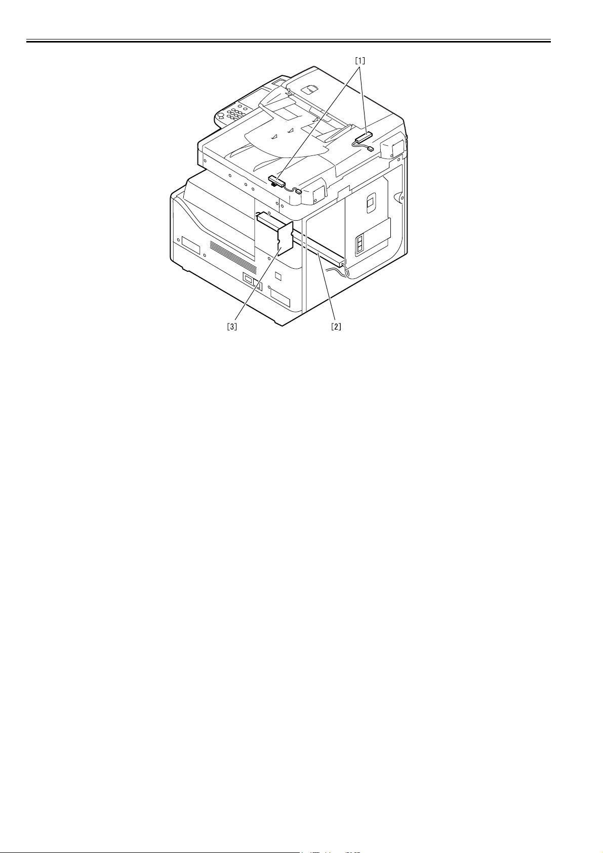
Chapter 1
F-1-2
[1] Reader Heater *1
[2] Cassette Heater *1
[3] Heater PCB
These parts are supplied as service parts, not the standard items.
*1: To operate the heaters, a heater PCB is required.
1.1.3 Printing/Transmitting Accessories System Configuration (MF7170i)
The configuration is as shown in the following figure:
0012-4536
1-2

[1]
[2]
Chapter 1
[3]
[5]
[4]
[6]
F-1-3
[1] PCL Printer Kit-K1 *1
[2] UFRII LT Printer Kit-J2 *1
[3] Serial Interface Board-A1
[4] Super G3 FAX Board-T1
[5] iR 256MB Expansion RAM-D1 *1
[6] Color SEND Kit (This item is not supplied as goods.) *1
*1: Standard equipment
1.1.4 Functions of the Printing/Transmission Functions (MF7170i)
The following is a brief explanation of the functions expected of the accessories; for details, see the chapters that follow:
T-1-1
UFR II print function (Resolution: 1200dpi)*1 ==> UFRII LT Printer Kit-J2
iR 256MB Expansion RAM-D1
0012-4872
PCL print function*1 ==> PCL Printer Kit-K1
FAX function ==> Super G3 FAX Board-T1
Coin vender function ==> Serial Interface Board-A1
1-3

Chapter 1
Color SEND function*1 ==> This function is not supplied as goods.
*1: Standard equipment
1.2 Product Specifications
1.2.1 Names of Parts
1.2.1.1 External View (MF7170i)
[11]
[10]
[9]
[8]
[1] DADF [9] Left door
[2] Reader front cover [10] Left cover (rear)
[3] Control panel [11] Reader left cover
[4] Delivery tray [12] Reader right cover
[5] Front cover [13] Reader rear cover
[6] Cassette 1 [14] Rear cover
[7] Left cover (front) [15] Right cover (upper)
[8] Manual feed tray [16] Right cover (lower)
1.2.1.2 Cross-Section
[1]
[12] [13]
[2]
[3]
[4]
[5]
[6]
[16]
[7] [15]
F-1-4
0012-4147
[14]
0012-3031
[1]
[18]
[17]
[16]
[15]
[14]
[13]
[2]
[3]
[4]
[5]
[6]
[12][11][10] [9] [8] [7]
F-1-5
1-4
[1] CIS unit [10] Separation roller
[2] Reader unit [11] Vertical path roller
[3] Laser scanner unit [12] Manual feed pickup roller
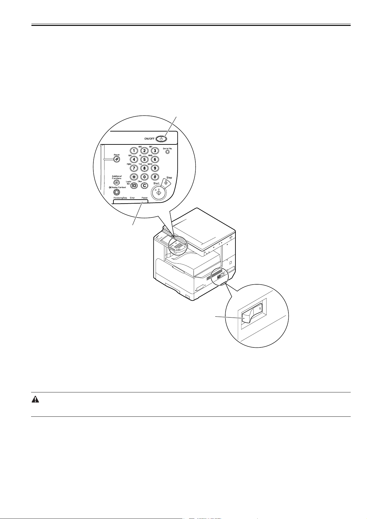
[4] DC power supply PCB [13] Registration roller
[5] HVT PCB [14] Transfer roller
[6] Cassette [15] Drum unit
[7] Toner cartridge [16] Pressure roller
[8] Pickup roller [17] Fixing film unit
[9] Feed roller [18] Delivery roller
1.2.2 Using the Machine
Chapter 1
1.2.2.1 Turning On the Power Switch
The machine possesses 2 power switches: main power switch and control power switch. Normally (i.e., unless the machine is in a sleep state), the machine will be
0012-3032
supplied with power when you turn on its main power switch.
[1]
[2]
[3]
F-1-6
[1]Control panel power switch
[2]Main power lamp
[3]Main power switch
1.2.2.2 When Turning Off the Main Power Switch
<During printing or fax data transmission/reception>
Be sure to operate the main power switch while the Processing/Data lamp on the control panel is not lit.
(Turning off the main switch during printing or fax data transmission/reception can erase the data being processed.)
0012-3034
1-5
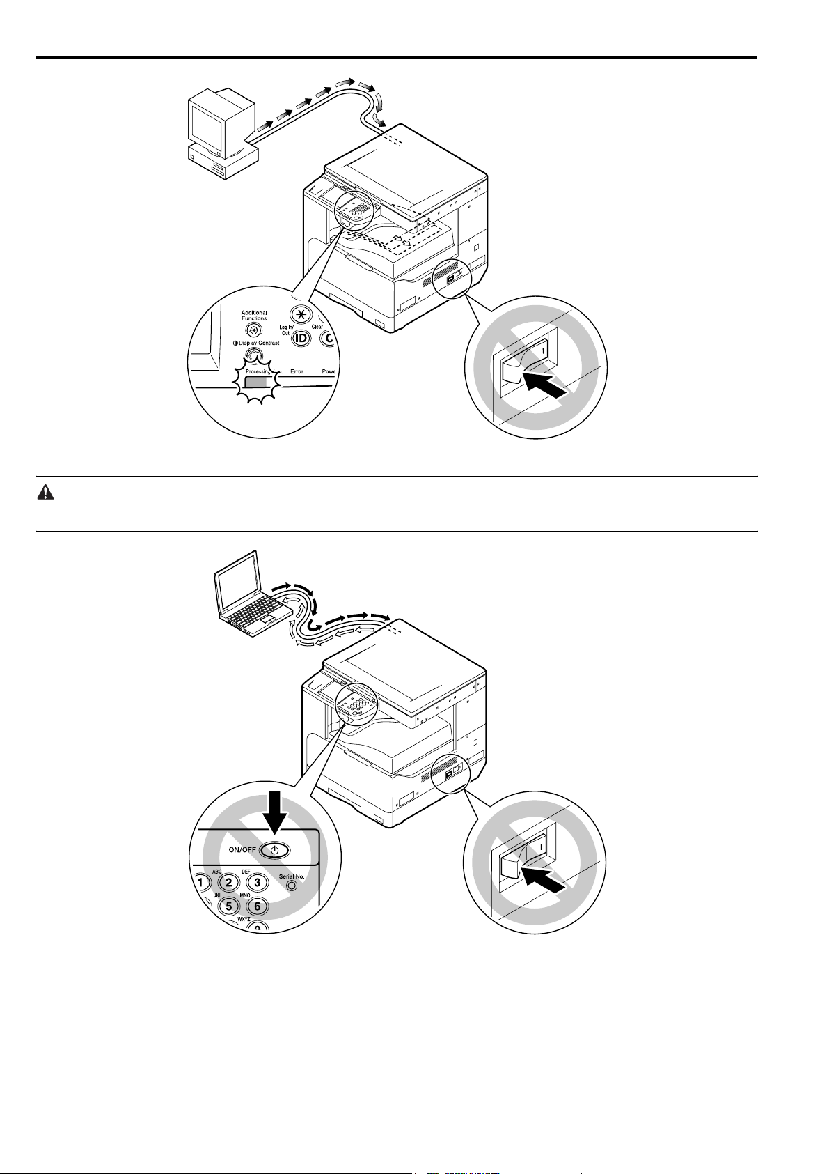
Chapter 1
F-1-7
<During downloading>
Do not turn off the power switch or ON/OFF switch on the control panel.
(Turning off the main power switch during downloading can make this machine inoperative.)
1-6
F-1-8
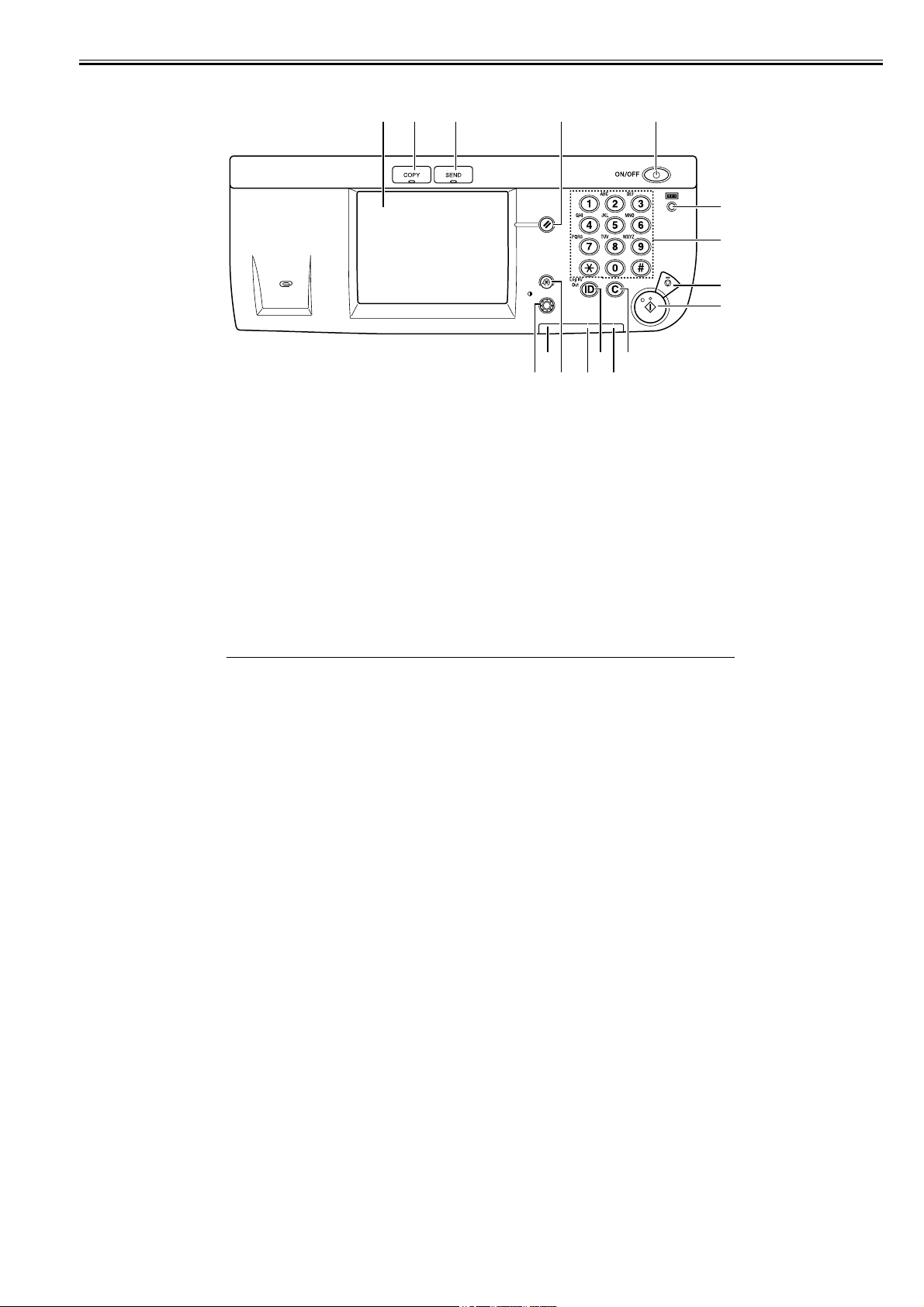
Chapter 1
9]
8]
7]
6]
1.2.2.3 Control Panel (MF7170i)
1.2.3 User Mode Items
[1]
[13] [11][16] [14]
F-1-9
[1] Touch Panel Display [9] Start key
[2] COPY key [10] Clear key
[3] SEND key [11] Main power indicator
[4] Reset key [12] Log IN/Out key
[5] Control panel power switch [13] Error indicator
[6] Counter Check key [14] Additional functions key
[7] Numeric keys [15] Processing/Date indicator
[8] Stop key [16] Display Contrast Dial
0012-4599
[5][2] [3] [4]
[
[
[
[
[10][15] [12]
1.2.3.1 Common Settings
Item Settings(*1 Indicates the default setting.)
T-1-2
Initial Function Select Initial Function: Copy*1, Send
Set System Monitor Screen as initial function: On, Off*1
Set [Device] as the default for System
Monitor: On*1, Off
Auto Clear Setting Initial Function*1, Selected Function
Audible Tones Entry Tone: On*1 (1* to 3 levels), Off
Error Tone: On*1 (1* to 3 levels), Off
Send Done Tone: On (1* to 3 levels), Off*1
Receive Done Tone: On (1* to 3 levels), Off*1
Print Done Tone: On*1 (1* to 3 levels), Off
Scan Done Tone: On*1 (1* to 3 levels), Off
Toner Save Mode High, Low, Off*1
Printer Density 1 to 9 levels; 5*1
Inch Entry On, Off*1
Drawer Eligibility For APS/ADS Copy: (Stack Bypass: On, Off*1, All Other Paper Sources: On*1, Off)
Printer: (Stack Bypass: cannot be set, All Other Paper Sources: On*1, Off)
Receive: (Stack Bypass: On, Off*1, All Other Paper Sources: On*1, Off)
Other: (Stack Bypass: On, Off*1, All Other Paper Sources: On*1, Off)
Register Paper Type Paper Drawer 1, Paper Drawer 2*2, Paper Drawer 3*2,
Paper Drawer 4*2: Plain*1, Recycled, Color, Bond,
Heavy Paper 1
Energy Consumption in Sleep
Low*1, High
Mode
Tray Designation*2 If the Optional Inner 2 Way Tray-E1 Is Attached
Tray A: Copy*1, Printer*1, Receive*1, Other*1
Tray B: Copy*1, Printer*1, Receive*1, Other*1
If the Optional Finisher-U1 and Additional Finisher Tray-C1 Are Attached
Tray A: Copy*1, Printer*1, Receive*1, Other*1
Tray B: Copy*1, Printer*1, Receive*1, Other*1
Stack Bypass Standard Settings On:Option, Off*1
Paper Feed Method Switch Stack Bypass, Paper Drawer 1, Paper Drawer 2*2,
Paper Drawer 3*2, Paper Drawer 4*2: Speed*1, Print
Side
Language Switch On, Off*1
Reversed Display (B/W) On, Off*1
Error Display for Dirty Feeder On*1, Off
Initialize Common Settings Initialize
0012-5645
1-7

Chapter 1
Item Settings(*1 Indicates the default setting.)
*2 Indicates items that appear only when the appropriate optional equipment is attached.
1.2.3.2 Timer Settings
Item Settings(*1 Indicates the default setting.)
Date & Time Settings Date and Time Setting (12 digit number)
Auto Sleep Time On*1 3 to 30 minutes; 5*1
Auto Clear Time 0 (Off) to 9 minutes, in one minute increments; 2 min.*1
1.2.3.3 Adjustment/Cleaning
Item Settings(*1 Indicates the default setting.)
Transfer Roller Cleaning Press [Start]
Fixing Unit Cleaning Press [Cleaning Sheet Print]
Feeder Cleaning Press [Start]
Special Mode M Normal*1, Low, High
Special Mode N On, Off*1
Special Mode O Stack Bypass: On, Off*1
Special Mode P On, Off*1
Bond Special Fixing Mode On, Off*1
Special Mode S Speed Priority 1, Speed Priority 2, Off*1
Auto Adjustment for Dirty Feeder On*1, Off
Maintenance Code This setting is not functional in this model.
1.2.3.4 Report Settings
Item Settings(*1 Indicates the default setting.)
Settings TX Report: On, For Error Only*1, Off
Print List Address Book List
1.2.3.5 System Settings
Item Settings(*1 Indicates the default setting.)
System Manager Settings
System Manager 32 characters maximum
System Manager ID Seven digit number maximum
System Password Seven digit number maximum
Department ID Management
Department ID Management On, Off*1
Register ID/Password Register, Edit, Erase
Page Totals Clear, Clear All Totals, Print List
Allow ID Unknown Printer Jobs On*1, Off
Network Settings
TCP/IP Settings
T-1-3
Time Zone Settings:
GMT -12:00 to GMT +12:00;
GMT -03:00*1
Daylight Saving Time Settings: On, Off*1
Off
T-1-4
Drawer: On, Off*1
T-1-5
Report With TX Image: On*1, Off
Activity Report
Auto Print: On*1, Off
Send/Receive Separate: On, Off*1
RX Report: On, For Error Only, Off*1
One-touch Buttons: Yes, No
Address Book: Yes, No
User's Data List: Yes, No
T-1-6
IP Address Settings IP Address, Subnet Mask, Gateway Address, DHCP, RARP, BOOTP
DNS Server Primary Server(DNS), Secondary Server (DNS), Host Name, Domain
Name
WINS Configuration WINS Resolution, WINS Server
Use LPD Print LPD Settings
RAW Settings Use RAW, Use Bidirectional
Use PASV Mode for FTP Use PASV Mode for FTP On/Off
FTP Extension FTP Extension On/Off
Use HTTP Use HTTP On/Off
Port Number Settings LPD, RAW, HTTP, SMTP, Receive, POP3 Receive, FTP Sending, SMTP
Sending, SNMP
IP Address Range Settings On/Off*1 A maximum of 4 IP addresses can be stored.
0012-5646
0012-5647
0012-5648
0012-5654
1-8

Item Settings(*1 Indicates the default setting.)
Receiving MAC Address
Settings
Apply Settings: On/Off
MAC addresses (a maximum of 5 addresses can be registered)
SMB Settings Use SMB Client, Server, Workgroup, Comment, LM Announce
SNMP Settings Use SNMP, Community Name, Writable SNMP
Enable Dedicated Port Settings On/Off
Ethernet Driver Settings Auto Detect, Communication Mode, Ethernet Type, MAC Address
E-Mail/I-Fax SMTP Receive, POP, POP Authentication before Send, SMTP Server, E-
mail Address, POP Server, POP Address, POP Password, POP Interval
Startup Time Settings 0 to 300 seconds 60*1
Forwarding Settings
Receive Type All*1, Fax, I-Fax
Validate/Invalidate On, Off*1
Register Condition Name: 50 characters maximum
Forward w/o Cond. Receive Type: Fax*1, I-Fax
Detail/Edit Condition Name: 50 characters maximum
Forwarding Conditions
Receive Type: Fax*1, I-Fax
Forwarding Destination: Select from the registered
addresses.
File Format: TIFF*1, PDF, Divide into Pages
Forwarding Destination: Select from the registered addresses.
File Format: TIFF*1, PDF, Divide into Pages
Forwarding Conditions
Receive Type: Fax*1, I-Fax
Forwarding Destination: Select from the registered addresses.
File Format: TIFF*1, PDF, Divide into Pages
Erase Yes, No
Print List Yes, No
Device Info Settings
Device Name 32 characters maximum
Location 32 characters maximum
User ID Management On, Off*1
Communications Settings
E-mail/I-Fax Maximum TX Data Size: 0 to 99 MB, in one MB increments, 3 MB*1
Devided TX over Max. Data Size: On, Off*1
Default Subject: 40 characters maximum
Fax Settings Send Start Speed, Receive Start Speed
R-Key Settings: PSTN*1/PBX
Memory Lock Settings On:Option, Off*1
Remote UI On/Off On*1, Off
Restrict Access to Destinations Restrict New Addresses: On, Off*1
Allow Fax Driver TX: On*1, Off
License Registration This setting is not functional in this model.
Department ID & User's Name On*1, Off
Job Log Display On*1, Off
Use USB Device On*1, Off
Chapter 1
1.2.3.6 Copy Settings
Item Settings(*1 Indicates the default setting.)
Image Orientation Priority On, Off*1
Auto Orientation On*1, Off
Standard Settings Store, Initialize
Initialize Copy Settings Yes, No
1.2.3.7 Communication Settings
Item Settings(*1 Indicates the default setting.)
Common Settings
T-1-7
0012-5655
0012-5656
T-1-8
1-9

Chapter 1
Item Settings(*1 Indicates the default setting.)
TX Settings Unit Name (24 characters maximum)
Data Compression Ratio: High Ratio, Normal*1, Low Ratio
Retry Times: 0 to 5 times; 3 times*1
Edit Standard Send Settings
Store, Initialize
TX Terminal ID
On*1 (Printing Position: Inside, Outside*1; Telephone # Mark: FAX*1,
TEL)
Gamma Value for Color Send Jobs: Gamma 1.0, Gamma 1.4, Gamma
1.8*1, Gamma 2.2
Sharpness: 1 to 7 levels, 4*1
Register Favorites Button: M1 to M18
Color TX Scan Settings: Speed Priority, Image Priority*1
Default Screen for Send: Favorite Buttons, One-touch Buttons, Initial
Function*1
Initialize TX Settings: Yes, No
RX Settings Two-sided Print: On, Off*1
Select Cassette
Switch A: On*1, Off
Switch B: On*1, Off
Switch C: On*1, Off
Switch D: On*1, Off
Receive Reduction
On*1 RX Reduction: Auto*1, Fix. Red.
Reduce %: 97, 95, 90*1, 75%
Reduce Direction: Ver. Hor.,
Vertical Only*1
Off
Continue Printing When Toner Is Out: Yes*1, No
Fax Settings
User Settings Unit Telephone # (20 characters maximum)
Tel Line Type: Tone*1, Pulse
Monitor Volume Control:
Volume Control: 0 to 3 levels, 1*1), Off (0)
TX Settings ECM TX: On*1, Off
Pause Time: 1 to 15 seconds; 2 seconds*1
Auto Redial
On*1 Option:
Redial Times: 1 to 10 times; 2 times*1
Redial Interval: 2 to 99 minutes; 2
minutes*1
TX Error Redial: On*1, Off
Off
Check Dial Tone Before Sending: On*1, Off
Rotate Send: On*1, Off
RX Settings ECM RX: On*1, Off
1.2.3.8 Printer Settings
T-1-9
Item Settings(* Indicates the default setting.)
Default Papersize A4*, A3, B4, B5, A5, 11X17, LGL, LTR, STMT, EXECUTIV, ISO-B5,
Default Papertype Plain Paper*, Color, Recycled, Heavy Paper 1, Heavy Paper 2, Heavy
Copies 1 to 999; 1*
2-Sided Printing Off*, On
Print Quality
Image Refinement On*, Off
Density 9 levels; 5*
Toner Saver Off*, On
Page Layout
Binding Long Edge*, Short Edge
Margin MM*: -50.0 MM to 50.0 MM; 0.0 MM*
Error Time Out On* (Time Out Period: 5 to 300 Sec), Off;15 Sec*
Collate Off*, Collate, Offset + Collate**, Offset + Group**, Staple** (Staple
Init. Printer Set Off*, On
Reset Printer Off*, On
PCL Settings
Orientation PortraitT*, Landscape
Font Number 0 to 120; 0*
ISO-C5, COM10, MONARCH, DL
Paper 3, Bond, Transparency, Labels, Envelope
Inches: -01.90 Inches to 01.90 Inches; 00.00 Inches*
Position: Top Left*, Top Right, Bottom Left)
0012-5660
1-10

Item Settings(* Indicates the default setting.)
Point Size 4.00 to 999.75 point; 12.00 point*
Pitch 0.44 to 99.99 cpi; 10.00 cpi*
Form Lines 5 to 128 lines; 64 lines*
Symbol Set PC8*, PC850, PC852, PC8DN, PC8TK,
Custom Paper Off*, On
Unit of Measure Millimeters*, Inches
X Dimension 148 mm to 432 mm (5.83" to 17.00"); 432 mm* (17.00")
Y Dimension 95 mm to 297 mm (3.75" to 11.69"); 297 mm* (11.69")
Append CR to LF No*, Yes
Enlarge A4 Off*, On
Two asterisks (**) indicate items that appear only when the appropriate optional equipment is attached.
PC1004, PIFONT, PSMATH, PSTEXT,
ROMAN8, VNINTL, VNMATH, VNUS,
WIN30, WINBALT, WINL1, WINL2, WINL5,
DESKTOP, ISO4, ISO6, ISO11, ISO15,
ISO17, ISO21, ISO60, ISO69, ISOL1,
ISOL2, ISOL5, ISOL6, LEGAL, MATH8,
MCTEXT, MSPUBL, PC775
Chapter 1
1.2.3.9 Address Book Settings
T-1-10
Item Settings(*1 Indicates the default setting.)
Register Address
Register New Add
Fax Fax Number: 120 characters maximum
E-mail E-mail Address: 120 characters maximum
I-Fax I-Fax Address: 120 characters maximum
File Protocol: FTP*1, Windows (SMB)
Group Erase
Erase Edit One-touch Buttons
Register/Edit You can register or edit the items of
Register Name: 16 characters maximum
Option: Sending Speed, Long Distance,
ECM TX
Register Name: 16 characters maximum
Register Name: 16 characters maximum
Host Name: 120 characters maximum
File Path: 120 characters maximum
User: 24 characters maximum (FTP, Windows (SMB))
Password: 24 characters maximum (FTP), 14 characters maximum
(Windows (SMB))
Register Name: 16 characters maximum
Address Book
Register Name: 16 characters maximum
One-touch Buttons for Fax, E-mail, I-Fax,
File, and Group shown in Register New Add
above.
Key Name: 12 characters maximum
1.2.3.10 Recommended setting of system management information
When multiple users use the machine, it is necessary to advise each user to set the system management information.
Setting ID and password of system administrator on the operation unit under (Additional functions key) > [System management setting] > [Setting of system administrator's information] has an effect of restraining the third person from falsifying information, for the ID and password are required when a user carries out an
important setting of the machine.
Under the environment that the setting is not done, if a user who does not sufficiently know operation situation of the machine tries to change the setting, following
troubles may occur.
- When the user changes [User ID Management] from [off] to [on], copying operation cannot be done unless ID and password are input.
- When each setting is changed on the network from RUI, that enables to falsify data of address book or delete log.
- When TCP/IP fixed address is changed on the network setting, printing operation via network cannot be done until the port setting is changed.
- When usage restriction of USB device is changed to [on], printing operation via USB becomes disabled.
1.2.3.11 The Reference Information of the Department ID Management
Function:
If Department is registered in Department ID Management, users are required to input the Department ID and password when inputting data from the operation
unit of the machine. Also, the registration enables to restrict usage and control the usage number of times of Total Parts, Copy, B&W Scan, Color Scan, or Print.
Setting method:
Register Department ID in Department ID Management under Additional Functions key>System Setting.
Operation outline:
Department ID can be registered in [Department ID management] from the operation unit of the machine even though [System Manager Settings] is not done.
When registering data in [Department ID Management] using RUI, you need to register yourself as a system manager in [System Manager Settings] and login
as a system manager.
0012-5657
0012-5704
0012-5705
1-11
 Loading...