

Page 1
Safety Instructions
MULTIMEDIA PROJECTOR
User’s Manual
Before Use
Installation Procedure
Basic Guide
Connection Procedure
Projection Procedure
Convenient Features
Using Menus
Advanced Guide
Menu Configuration
Menu Description
Advanced Projection
Other Information
Maintenance
Product Specifications
Troubleshooting
ENG
Page 2
How to Use This Manual
Thank you for purchasing a Canon projector.
The WUX6500 Multimedia Projector is a high-performance projector that is
capable of projecting a high-resolution computer screen and high-quality
digital image on a large screen.
This Manual
This is the user’s manual for WUX6500 Multimedia Projectors (hereafter,
“projector”). The “Basic Guide” section describes installation and basic use of the
projector. Descriptions of menus and how to connect the projector to a network are
given in the “Advanced Guide” section. Read this manual thoroughly to make the
most of your projector. We recommend requesting installation by a qualified
technician or the Canon Customer Support Center.
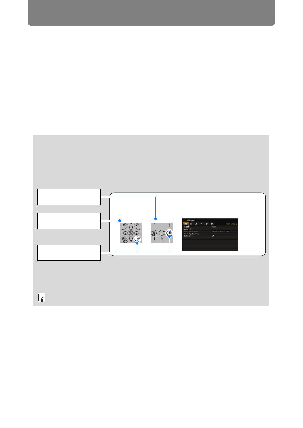
Symbols of Button Operations
The projector can be operated using the buttons on the remote control or on the
side of the projector. The remote control allows you to operate all functions of the
projector.
In this document, the button’s operations are shown as below.
Operation of buttons
on side of projector
Remote control button
operation
Indicate the buttons to
be pressed
Selecting Screen Aspect
Select the correct aspect ratio for the screen which is used.
1
Press the MENU button to display the menu window.
Remote control Projector
Symbols Used in This Manual
Sections labeled with these symbols give the following kinds of information.
Indicates precautions and information to note when using the projector.
2
Page 3

Table of Contents
How to Use This Manual............... 2
Projector Highlights...................... 5
Safety Instructions........................ 7
Safety Precautions................................. 8
CAUTION ON HANGING FROM THE
CEILING .................................................. 8
AC Power Cord Requirement.............. 11
Federal Communication Commission
Notice .................................................... 12
Precautions for Use ............................. 14
Installation and Handling
Precautions .......................................... 15
Precautions on the Lamp .................... 17
Precautions for the Batteries of the
Remote Control .................................... 18
For Safe Use ................................ 20
Before Installation....................... 22
Precautions When Carrying/Shipping
the Projector......................................... 22
Precautions for Installation................. 22
Open Source Software ............... 27
Before Use ................................... 28
Included Accessories .......................... 28
Part Names ........................................... 29
Projector ............................................... 29
Side Control.......................................... 30
LED Indicators...................................... 31
Input Terminal ...................................... 33
Remote Control .................................... 35
Preparing the Remote Control............ 37
Basic Guide ............................39
Installation Procedure ................ 40
Setting Up the Projector...................... 40
Relationship Between Image Size and
Projecting Distance ............................. 43
Lens Shift Function ............................. 47
Connection Procedure ............... 49
Connecting a Computer ...................... 49
Connecting AV Equipment.................. 51
Plugging the Projector In .................... 52
Projection Procedure.................. 53
Step 1 Turn the Projector On .............. 53
Step 2 Select an Input Signal.............. 56
Step 3 Adjust the Image ...................... 57
Step 4 Select an Aspect Ratio (Screen
Aspect) Matching the Screen.............. 63
Step 5 Adjusting Keystone
Distortion .............................................. 67
Step 6 Select the Image Quality (Image
Mode) .................................................... 70
Step 7 Turn the Projector Off.............. 71
Convenient Features...................72
Adjusting the Volume .......................... 74
Muting the Sound................................. 74
Zooming Part of an Image................... 75
Advanced Guide ....................77
Using Menus ................................78
Menu Configuration ............................. 78
Basic Menu Operations ....................... 79
Menu Configuration ....................81
Menu Description ........................90
Input settings ....................................... 90
Image adjustment ................................ 96
Install settings.................................... 104
System settings ................................. 116
Network settings ................................ 127
Completing Projector Settings ......... 129
Completing Computer Settings ........ 136
Checking Projector Information ....... 156
Advanced Projection.................157
Projecting Images on a USB Flash
Drive .................................................... 157
Description of USB File Browser...... 159
Selecting an Image for Projection .... 160
Operating the Projected Image......... 160
Running a Slideshow of Data Saved in a
USB Flash Memory ............................ 161
Split-Screen Display .......................... 161
Projecting from Multiple Projectors at
Once (Edge Blending) ....................... 162
Other Information ................169
Maintenance...............................170
Cleaning the Projector and the Air
Filter .................................................... 170
Cleaning the Air Filter........................ 171
Replacing the Air Filter...................... 172
Replacing the Lamp........................... 173
Replacement Lamp ............................ 175
3
Page 4

Table of Contents
Lamp Replacement Procedure ......... 176
Installing / Removing the Lens
Unit ...................................................... 178
Product Specifications ............. 183
Relationship between Aspect and
Screen Aspect .................................... 183
Displayed Test Patterns .................... 187
Supported Signal Types.................... 188
Troubleshooting........................ 198
LED Indicator Details......................... 198
Symptoms and Solutions.................. 199
Index........................................... 205
Option ........................................ 207
4
Page 5
ENG
Waarschuwing
Avvertenza
Storethisdocumenttogetherwiththe“ImportantInformation”
(booklet)andthe“User’sManual”(CD-ROM).
Installation and Handling Precautions
Précautions d’installation et de manipulation
Precauciones de instalación y manejo
Hinweise zur Aufstellung und Handhabung
Precauzioni relative all’installazione e a come si
maneggia il proiettore
Voorzorgsmaatregelen voor installatie en
behandeling
Forsigtighedsregler ved installation og håndtering
Försiktighetsåtgärder vid montering och hantering
Asennusta ja käsittelyä koskevat varotoimet
安装和搬运注意事项
설치 및 취급 절차
安裝與使用注意事項
設置および取り扱い上のご注意
YT1-7519-000 ©CANONINC.2017
Installation and Handling Precautions
• Donotinstalltheprojectorinalocationthatisdamp,orwherethere
isalotofdust,oilysmokeortobaccosmoke.Doingsocouldcause
contaminationofopticalcomponentssuchasthelensandthemirror
andmayresultindeteriorationofimagequality.Inaddition,oilcan
degradetheplastic,whichcouldresultinaceiling-mountedprojector
fallingfromitsmounting.
• Donotuseadhesives,lubricants,oils,oralkalinedetergentsfor
maintenanceoftheprojector.Theycouldadheretotheplasticand
deteriorateit,possiblyresultingintheprojectorfallingifitisceilingmounted.
• Makesuretoimplementanti-fallmeasuressuchasananti-fallwire
wheninstallingtheprojectorinhighplaces,forexample,installingit
ontheceiling.
FRA
Conservezcedocumentavecles«Informationsimportantes»
(livret)etle«Moded’emploi»(CD-ROM).
Avertissement
Précautions d’installation et de manipulation
• N’installezpasleprojecteurdansunendroithumideoutrès
poussiéreux,oudanslequelilseraitexposéàdesfuméescontenant
desparticulesdegraisseoudetabac.Lescomposantsoptiques,
commel’objectifoulemiroir,pourraientêtrecontaminés,etla
qualitédel’imageenseraitaltérée.Deplus,l’huilepeutdétériorerle
plastique,cequipourraitprovoquerlachuteduprojecteurmontéau
plafond.
• N’utilisezpasdecolle,delubriants,d’huilesoudedétergents
alcalinspourl’entretienduprojecteur.Ilspourraientsecollerau
plastiqueetl’endommager,cequipourraitprovoquerlachutedu
projecteurs’ilestmontéauplafond.
• Veillezàmettreenplacedesmesuresantichutetellesqu’uncâble
antichutelorsdel’installationduprojecteurenhauteur,parexemple
Attention
auplafond.
SPA
Guardeestedocumentojuntoconla“Informaciónimportante”
(folleto)ylas“Instruccionesdeuso”(CD-ROM).
Advertencia
Precauciones de instalación y manejo
• Noinstaleelproyectorenunlugarhúmedoodondehayapolvo,
humodetabacoograsa.Dehacerlo,loscomponentesópticos
comolalenteyelespejopodríanensuciarse,afectandoalacalidad
deimagen.Además,lagrasapuededegradarelplástico,locual
podríacausareldesprendimientodelproyectormontadoeneltecho
respectodesumontura.
• Noutiliceadhesivos,lubricantes,aceitesodetergentesalcalinos
paraelmantenimientodelproyector.Talessustanciaspodrían
adherirsealplásticoydeteriorarlo,loquepodríacausarlacaídadel
proyectorsiestámontadoeneltecho.
• Alinstalarelproyectorenlugareselevados,comoporejemploen
eltecho,asegúresedetomarmedidascontralacaídadelaparato,
Atención
ITA
Precauzioni relative all’installazione e a come si maneggia il proiettore
Attenzione
talescomoelusodeuncabledesujeción.
Conservarequestodocumentoinsiemea“Informazioniimportanti”
(opuscolo)eal“Manualed’uso”(CD-ROM).
• Noninstallareilproiettoreinluoghiumidioinpresenzadigrandi
quantitatividipolvere,fumooleosoofumoditabacco.Incasocontrario,
sipotrebbeprovocarelacontaminazionedeicomponentiotticiquali
l’obiettivoelospecchio,eprovocareildeterioramentodellaqualità
dell’immagine.Inoltre,l’oliopuòdegradarelaplastica,ilchepotrebbe
risultarenellacadutadiunproiettoremontatoasofttodalsuoattacco.
• Nonutilizzareadesivi,lubricanti,oliodetergentialcaliniperla
manutenzionedelproiettore.Potrebberoaderireallaplasticae
deteriorarla,conlapossibilitàdicausarelacadutadelproiettore,
qualorasiamontatoasoftto.
• Quandosiintendeinstallareilproiettoreinubicazionielevate,ad
esempioquandosiintendeinstallarlosulsoftto,accertarsidi
implementaremisurediprevenzionedellecadute,adesempioun
cavometallicoanticaduta.
GER
BewahrenSiediesesDokumentzusammenmit„WichtigeInformationen“(Broschüre)unddem„Benutzerhandbuch“(CD-ROM)auf.
Warnung
Hinweise zur Aufstellung und Handhabung
• StellenSiedenProjektornichtaneinemOrtauf,andemerFeuchtigkeit,
Staub,starkenÖldünstenoderZigarettenrauchausgesetztist.Andernfalls
könntendieoptischenBauteile(Objektiv,Spiegel)verschmutztwerden,
waszueinerVerschlechterungderBildqualitätführenwürde.Darüber
hinauskannÖldenKunststoffzersetzen.Dieskanndazuführen,
dasseinanderDeckemontierterProjektorausseinerHalterungfällt.
• VerwendenSiekeineKlebstoffe,Schmiermittel,Öleoderalkalische
ReinigungsmittelfürdieWartungdesProjektors.Siekönntenan
demKunststoffanhaftenundihnbeschädigen.Dieskanndazu
führen,dassderProjektorherunterfällt,wenneraneinerDecke
montiertist.
• AchtenSiedarauf,dassderProjektorbeiderMontageineiner
hohenPosition(z.B.anderDecke)gegenAbsturzgesichertwird(z.
Vorsicht
NLD
Voorzorgsmaatregelen voor installatie en behandeling
Voorzichtig
B.miteinemDrahtseil).
Bewaarditdocumentsamenmethetboekje„Belangrijke
informatie”ende„Gebruikershandleiding”(CD-ROM).
• Installeerdeprojectornietineenvochtigeofstofgeruimteofopeen
plaatsmetvettigerookoftabaksrook.Ditkanverontreinigingvan
deoptischecomponentenzoalsdelensendespiegelveroorzaken
enkanverslechteringvandebeeldkwaliteittotgevolghebben.
Daarnaastkunnenvetenoliehetkunststofaantastenwaardooreen
projectordieaanhetplafondisbevestigd,zoukunnenvallen.
• Gebruikvoorhetonderhoudvandeprojectorgeenhechtmiddelen,
smeerolie,andereolieofalkalischeschoonmaakmiddelen.Deze
blijvenmogelijkachterophetkunststof,waardoorditwordt
aangetast.Hierdoorzoudeprojectorkunnenvallenalsdezeaanhet
plafondisgemonteerd.
• Zorgervoordatuvalpreventiemaatregelenneemt,bijvoorbeelddoor
eenveiligheidskabeltegebruiken,alsudeprojectoropeenhoge
plaatsinstalleert,bijvoorbeeldaanhetplafond.
Page 6
Varning
Advarsel
DEN
警告
Varoitus
Opbevardettedokumentsammenmed”Vigtigeoplysninger”
(hæfte)og”Brugervejledningen”(CD-ROM).
SWE
Förvaradethärdokumentettillsammansmed”Viktiginformation”
(häfte)och”Användarhandbok”(CD-ROM).
Forsigtighedsregler ved installation og håndtering
• Undladatinstallereprojektorenetsted,dererfugtigt,ellerhvorder
ermegetstøv,oliedampeellercigaretrøg.Ellerskandetresultere
i,atdeoptiskedele,somf.eks.linsenogspejlet,kontamineres,og
billedkvalitetenforringes.Desudenkanolienedbrydeplastikken,
hvilketkanmedføre,atenloftsmonteretprojektorfaldernedfrasin
montering.
• Undladatbrugeklæbestoffer,smøremidler,olierelleralkaliske
rengøringsmidlertilatvedligeholdeprojektoren.Dekansætte
sigfastpåplastikkenogforringedenogmuligvismedføre,at
projektorenfalderned,hvisdenermonteretiloftet.
• Sørgforatbenytteforholdsreglertilforebyggelseaffald,for
eksempelensikkerhedsline,nårprojektorenmonterespå
Forsigtig
FIN
Asennusta ja käsittelyä koskevat varotoimet
Huomio
højtliggendesteder,foreksempelnårdenmonteresiloftet.
Säilytätämäasiakirjayhdessätuotteiden”Tärkeäätietoa”
(kirjanen)ja”Käyttöopas”(CD-ROM)kanssa.
• Äläasetaprojektoriapaikkaan,jokaonkostea,jossaonpaljon
pölyä,öljyistäsavuataitupakansavua.Sesaattaajohtaaoptisten
osien,kutenobjektiivinjapeilinlikaantumiseen,sekäsaattaa
heikentääkuvanlaatua.Lisäksiöljyvoiheikentäämuovia,
mikävoiaiheuttaakattoonasennetunprojektorinputoamisen
kiinnityksestään.
• Äläkäytäliimoja,voiteluaineita,öljyjätaiemäksisiäpuhdistusaineita
projektorinhuoltamisessa.Nevoivatkiinnittyämuoviinjaheikentää
sitä,mikävoijohtaaprojektorinputoamiseen,josseonkiinnitetty
kattoon.
• Varmista,ettäteetkaikkiputoamisenestävättoimenpiteet,kuten
putoamisenestävävaijeri,kunasennatprojektorinkorkealle,
esimerkiksiasennatsenkattoon.
Försiktighetsåtgärder vid montering och hantering
• Monterainteprojektornpåenplatssomärfuktigellerdärdetnns
mycketdamm,oljigrökellertobaksrök.Dettakanförorenaoptiska
komponenter,t.ex.linsochspegel,ochkanledatillförsämrad
bildkvalitet.Dessutomkanoljabrytanedplasten,vilketkanledatill
attprojektornfallernedfrånsittfästeomdenärtakmonterad.
• Användintelim,smörjmedel,oljorelleralkaliskarengöringsmedel
vidunderhålletavprojektorn.Sådanaämnenkanklibbafastpå
plastenochbrytanedellerpåannatsättskadaden,vilketeventuellt
kanledatillattprojektornfallernedomdenärtakmonterad.
• Användalltidenfallskyddskabelellervidtagandra
fallskyddsåtgärdernärdumonterarprojektornpåhögtuppsatta
Observera
CHI
platser,tillexempelvidmonteringitaket.
请将此文与“使用说明书(手册、CD-ROM)一起保管。
安装和搬运注意事项
•切勿将投影机安装在潮湿或多尘、有油烟或香烟烟
雾的地方。否则可能会污染光学部件(如镜头和反光
镜),会导致影像质量下降。此外,油会侵蚀塑料,
降低其性能,有可能会导致安装在天花板上的投影
机从其安装位置掉落。
•请勿使用粘合剂、润滑剂、机油或碱性除垢剂来维
护投影机。这些物质可能会附着在塑料上并对其造
成损坏,如果投影机安装在天花板上,有可能导致
投影机掉落。
•在高处安装投影机时(如将其安装在天花板上),请
务必采取防坠落措施,如防坠落金属丝。
KOR
이종이를[중요정보(책자)]및[사용설명서(CD-ROM)]와함께
보관해주십시오.
설치 및 취급 절차
• 습기나 먼지, 유연이나 담배 연기가 많은 장소에는 설치하지
마십시오.렌즈나미러등의광학부품에이물질이부착되어화질을
손상시키는원인이될수있습니다.또한오일은플라스틱의품질을
저하시켜천정에장착된프로젝터가떨어질수있습니다.
• 프로젝터의 유지관리를위해접착제,윤활제,오일또는알칼리성
ᔹヱ
〭⺉
세제를 사 용하지 마십시오. 플라스틱에 접착되어 플라스틱을
손상시킬 수 있으며 프로젝터가 천장에 장착된 경우 떨어질 수
있습니다.
• 프로젝터를 높은곳에 설치할 때(예:천장에설치)는 낙하방지
와이어와같은낙하방지조치를취하십시오.
Ꮾᐑ
FOR
請將此文與“重要資訊”和“使用說明書(CD_ROM)一同保管。
安裝與使用注意事項
•請勿將投影機安裝在潮濕或者有很多灰塵、油煙或香菸煙霧的地
方。這樣做可能會使得鏡頭與鏡片之類光學組件被污染,而且可
能會造成影像品質劣化。此外,油會讓塑膠劣化,而這可能會使
得安裝在天花板上的投影機從其安裝處掉下來。
•請勿使用黏性、潤滑、油性或鹼性清潔劑保養投影機。它們可能
會附著在塑膠上而令其劣化,如果投影機安裝在天花板上,可能會
造成投影機掉下來。
•將投影機安裝在 高處如天花 板上時,務 必要採取防 止掉落的措
施,例如,防止掉落的鋼纜。
JPN
この紙を「重要なお知らせ(冊子)」および「使用説明書(CDROM)」と一緒に保管してください。
設置および取り扱い上のご注意
• 湿気やホコリ、油煙やタバコの煙が多い場所には設置しないで
ください。レンズやミラーなどの光学部品に汚れが付着して、
画質を損なう原因になることがあります。また、油により樹脂
が劣化し、天吊り設置の場合に落下するおそれがあります。
• 本機のメンテナンスの際に接着剤、潤滑剤、油、アルカリ性洗
剤などを使用しないでください。付着すると樹脂が劣化し、天
吊り設置の場合に落下するおそれがあります。
• 天吊りのように高所に設置する場合は必ず落下防止ワイヤーな
どの落下防止措置をプロジェクター本体に施してください。
Page 7
Projector Highlights
High-Resolution LCOS Projection
Projection at 1920x1200 (WUXGA), thanks to high-resolution reflective liquid
crystal on silicon (LCOS) panels.
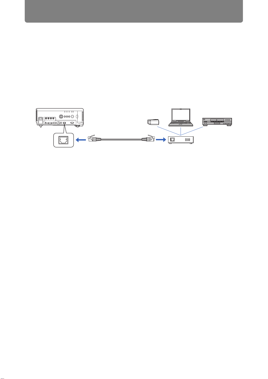
HDBaseT Input
The projector supports HDBaseT, a next-generation connectivity standard.
HDBaseT offers a convenient connection for carrying high-quality video and audio
signals equivalent to HDMI across distances up to 100 m over a single LAN cable.
This port can also be used to connect the projector to a network.
(P50, P51, P120, P121, P127)
HDMI cable, etc.
HDBaseT terminal
LAN cable
(CAT5e or better;
shielded; not included)
HDBaseT transmitter
Lens Shift
Lens shift enables motorized image repositioning up, down, left, or right (P47) for
greater freedom in installation.
Motorized Zoom and Focus Adjustment
Efficient setup using motorized zoom and focus adjustment.
Five Lens Units Available
Choose the optimal lens unit for the projection distance or purpose.
5
Page 8
Projector Highlights
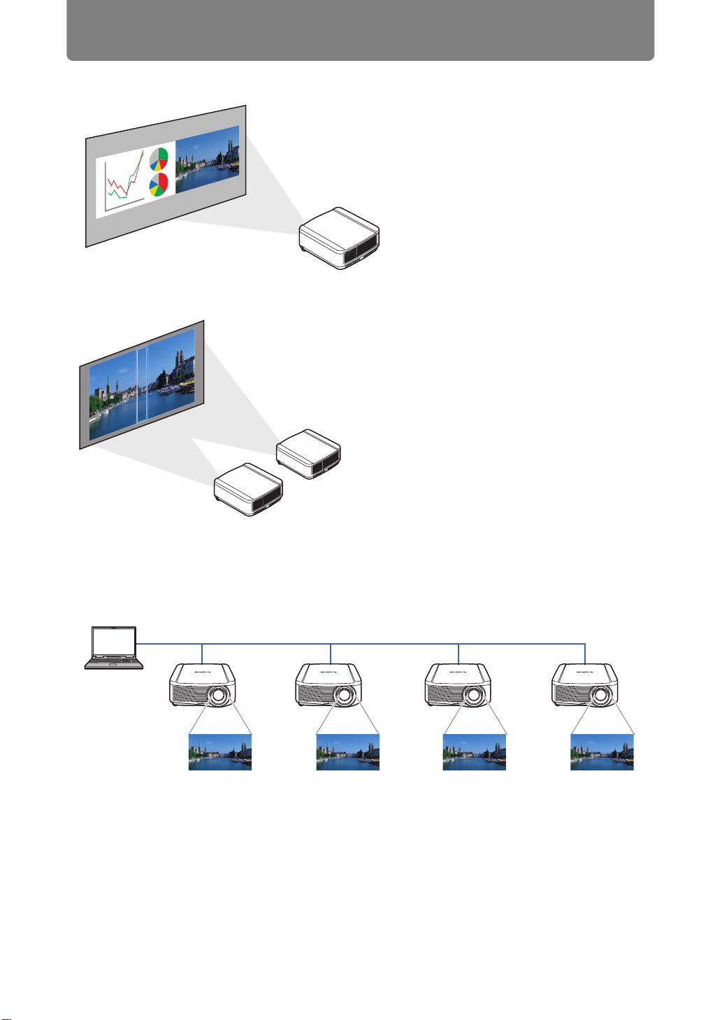
Split-Screen Display
Edge Blending
Splits the screen for projection of
two separate input signals at once.
(P161)
Blend the overlapping edges of images
from multiple projectors to make the
overall image more seamless. (P162)
Networked Multi-Projection (NMPJ)
Project images from multiple computers via a network connection.
For details on Networked Multi-Projection (NMPJ), refer to the NMPJ user’s
manual.
LAN
6
Page 9
Safety Instructions
Before installing and operating the projector, read this manual thoroughly.
This projector provides many convenient features and functions. Operating the
projector properly enables you to manage those features and maintain it in good
condition for many years to come.
Improper operation may result in not only shortening the product life, but also
malfunctions, fire hazards, or other accidents.
If your projector does not seem to be operating properly, read this manual again,
check operations and cable connections, and try the solutions in the
“Troubleshooting” section in the back of this manual. If the problem still persists,
contact the Canon Customer Support Center.
CAUTION
RISK OF ELECTRIC SHOCK
DO NOT OPEN
CAUTION: TO REDUCE THE RISK OF ELECTRIC SHOCK, DO NOT
REMOVE COVER (OR BACK). NO USER-SERVICEABLE PARTS
INSIDE EXCEPT LAMP REPLACEMENT. REFER SERVICING TO
QUALIFIED SERVICE PERSONNEL.
Safety Instructions
THIS SYMBOL INDICATES THAT DANGEROUS VOLTAGE
CONSTITUTING A RISK OF ELECTRIC SHOCK IS PRESENT
WITHIN THIS UNIT.
THIS SYMBOL INDICATES THAT THERE ARE IMPORTANT
OPERATING AND MAINTENANCE INSTRUCTIONS FOR THIS
UNIT IN THE OWNER’S MANUAL.
CAUTION
Not for use in a computer room as defined in the Standard for the Protection of
Electronic Computer / Data Processing Equipment, ANSI / NFPA 75.
7
Page 10
Safety Instructions
Safety Precautions
WARNING:
• THIS APPARATUS MUST BE GROUNDED.
• TO REDUCE THE RISK OF FIRE OR ELECTRIC SHOCK, DO NOT EXPOSE
THIS APPLIANCE TO RAIN OR MOISTURE.
• This projector produces intense light from the projection lens. Do not stare
directly into the lens, otherwise eye damage could result. Be especially careful
that children do not stare directly into the beam.
• Install the projector in a proper position. Otherwise it may result in a fire hazard.
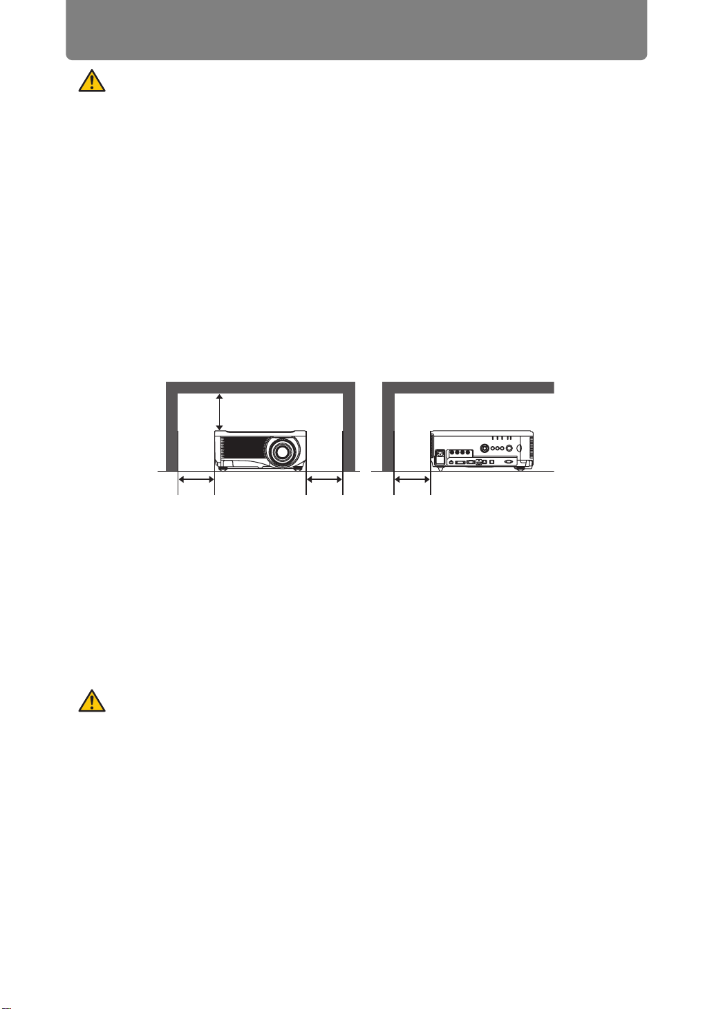
• Allowing the proper amount of space on the top, sides, and rear of the projector
cabinet is critical for proper air circulation and cooling of the unit. The diagrams
shown here indicates the minimum space required. If the projector is to be built
into a compartment or similarly enclosed, these minimum distances must be
maintained.
SIDE and TOP REAR
At least
50 cm (1.6')
At least
50 cm (1.6')
• Do not cover the ventilation slots on the projector. Heat build-up can reduce the
service life of your projector, and can also be dangerous.
• If the projector is unused for an extended time, unplug the projector from the
power outlet.
• Do not project the same image for a long time.
An afterimage may remain on the LCD panels due to the characteristics of the
panels of the projector.
At least
50 cm (1.6')
At least
50 cm (1.6')
CAUTION ON HANGING FROM THE CEILING
When hanging the projector from the ceiling, clean the air intake vents and top of
the projector periodically with a vacuum cleaner. If you leave the projector unclean
for a long time, the cooling fans can be clogged with dust, and it may cause a
breakdown or a disaster.
DO NOT SET THE PROJECTOR IN GREASY, WET, OR SMOKY CONDITIONS
SUCH AS IN A KITCHEN TO PREVENT A BREAKDOWN OR A DISASTER. IF
THE PROJECTOR COMES IN CONTACT WITH OIL OR CHEMICALS, IT MAY
BECOME DETERIORATED.
8
Page 11

Safety Instructions
■ READ AND KEEP THIS OWNER’S MANUAL FOR LATER
USE.
All the safety and operating instructions should be read before beginning to operate
the product.
Read all of the instructions given here and retain them for later use. Unplug this
projector from the AC power supply before cleaning. Do not use liquid or aerosol
cleaners on the projector. Use a damp cloth for cleaning.
Follow all warnings and instructions marked on the projector.
For added protection of the projector during a lightning storm, or when it is left
unattended or unused for long periods of time, unplug it from the wall outlet. This
will prevent damage due to lightning and power surges.
Do not expose this unit to rain or use near water... for example, in a wet basement,
near a swimming pool, etc...
Do not use attachments not recommended by the manufacturer as they may result
in hazards.
Safety Instructions
Do not place this projector on an unstable cart, stand, or table. The projector may
fall, causing serious injury to a child or adult, and serious damage to the projector.
Use only with a cart or stand recommended by the manufacturer, or sold with the
projector. Wall or shelf mounting should be carried out in accordance with the
manufacturer’s directions, and should use a mounting kit approved by the
manufacturers.
An appliance and cart combination should be moved with care.
Sudden stops, excessive force, and uneven surfaces may cause
the appliance and cart combination to overturn.
Slots and openings in the rear and front of the cabinet are provided
for ventilation, to insure reliable operation of the equipment and to protect it from
overheating.
The openings should never be covered with cloth or other materials, and the
bottom opening should not be blocked by placing the projector on a bed, sofa, rug,
or other similar surface. This projector should never be placed near or over a
radiator or heat register.
This projector should not be placed in a built-in installation such as a book case
unless proper ventilation is provided.
9
Page 12

Safety Instructions
Never push objects of any kind into this projector through cabinet slots as they may
touch dangerous voltage points or short out parts that could result in a fire or
electric shock. Never spill liquid of any kind onto the projector.
Do not install the projector near the ventilation duct of air-conditioning equipment.
This projector should be operated using only the type of power source indicated on
the marking label. If you are not sure of the type of power supplied, contact the
Canon Customer Support Center or local power company.
Do not overload wall outlets and extension cords as this can result in fire or electric
shock. Do not allow anything to rest on the power cord. Do not locate this projector
where the cord may be damaged by people walking on it.
Do not attempt to service this projector yourself as opening or removing covers
may expose you to dangerous voltages or other hazards. Refer all servicing to
qualified service personnel.
Unplug this projector from the wall outlet and refer servicing to qualified service
personnel under the following conditions:
a. When the power cord or plug is damaged or frayed.
b. If liquid has been spilled into the projector.
c. If the projector has been exposed to rain or water.
d. If the projector does not operate normally after following the operating
instructions. Adjust only those controls that are covered in the operating
instructions as improper adjustment of other controls may result in damage and
will often require extensive work by a qualified technician to restore the projector
to normal operating condition.
e. If the projector has been dropped or the cabinet has been damaged.
f. When the projector exhibits a distinct change in performance-this indicates a
need for servicing.
When replacement parts are required, be sure the service technician uses
replacement parts specified by the manufacturer that have the same characteristics
as the original parts. Unauthorized substitutions may result in fire, electric shock, or
injury.
Upon completion of any service or repairs to this projector, ask the service
technician to perform routine safety checks to determine that the projector is in safe
operating condition.
10
Page 13
Safety Instructions
AC Power Cord Requirement
The AC Power Cord supplied with this projector meets the requirements for use in
the country you purchased it.
AC Power Cord for the United States and Canada:
The AC Power Cord used in the United States and Canada is
listed by the Underwriters Laboratories (UL) and certified by
the Canadian Standard Association (CSA).
The AC Power Cord has a grounding-type AC line plug. This is
a safety feature to ensure the plug fits into the power outlet. Do
not try to tamper with this safety feature. Should you be unable
to insert the plug into the outlet, contact your electrician.
THE SOCKET-OUTLET SHOULD BE INSTALLED NEAR THE EQUIPMENT AND
EASILY ACCESSIBLE.
For the U.S. and Canada, LAMP (S) INSIDE THIS PRODUCT CONTAIN
MERCURY AND MUST BE RECYCLED OR DISPOSED OF ACCORDING
TO LOCAL, MUNICIPAL, STATE, PROVINCIAL, OR FEDERAL LAWS.
For lamp recycling and disposal information please call 1-800-OK-CANON
for the U.S. and Canada.
Ground
Safety Instructions
Only for European Union and EEA (Norway, Iceland and
Liechtenstein)
These symbols indicate that this product is not to be disposed of
with your household waste, according to the WEEE Directive (2012/
19/EU), the Battery Directive (2006/66/EC) and/or national
legislation implementing those Directives.
If a chemical symbol is printed beneath the symbol shown above, in
accordance with the Battery Directive, this indicates that a heavy
metal (Hg = Mercury, Cd = Cadmium, Pb = Lead) is present in this
battery or accumulator at a concentration above an applicable
threshold specified in the Battery Directive.
This product should be handed over to a designated collection point,
e.g., on an authorized one-for-one basis when you buy a new similar
product or to an authorized collection site for recycling waste
electrical and electronic equipment (EEE) and batteries and
accumulators. Improper handling of this type of waste could have a
possible impact on the environment and human health due to
potentially hazardous substances that are generally associated with
EEE. Your cooperation in the correct disposal of this product will
contribute to the effective usage of natural resources.
For more information about the recycling of this product, please
contact your local city office, waste authority, approved scheme or
your household waste disposal service or visit
www.canon-europe.com/weee
, or www.canon-europe.com/battery.
11
Page 14

Safety Instructions
Federal Communication Commission Notice
This device complies with Part 15 of the FCC Rules. Operation is subject to the
following two conditions:
1. This device may not cause harmful interference, and
2. This device must accept any interference received, including interference that
may cause undesired operation.
Note: This equipment has been tested and found to comply with the limits for a
Class A digital device, pursuant to Part 15 of the FCC Rules. These limits are
designed to provide reasonable protection against harmful interference when the
equipment is operated in a commercial environment. This equipment generates,
uses, and can radiate radio frequency energy and, if not installed and used in
accordance with the instruction manual, may cause harmful interference to radio
communications. Operation of this equipment in a residential area is likely to
cause harmful interference in which case the user will be required to correct the
interference at his own expense. The cable with a ferrite core provided with the
projector must be used with this equipment in order to comply with Class A of the
FCC Rules. Use of a shielded cable is required to comply with Class A of FCC
Rules. Do not make any changes or modifications to the equipment unless
otherwise specified in the instructions. If such changes or modifications should be
made, you could be required to stop operation of the equipment.
Warning:
This is a class A product. In a domestic environment this product may cause radio
interference in which case the user may be required to take adequate measures.
The cable with a ferrite core provided with the projector must be used with this
equipment in order to comply with Class A .
Use of a shielded cable is required to comply with Class A .
12
Page 15
Safety Instructions
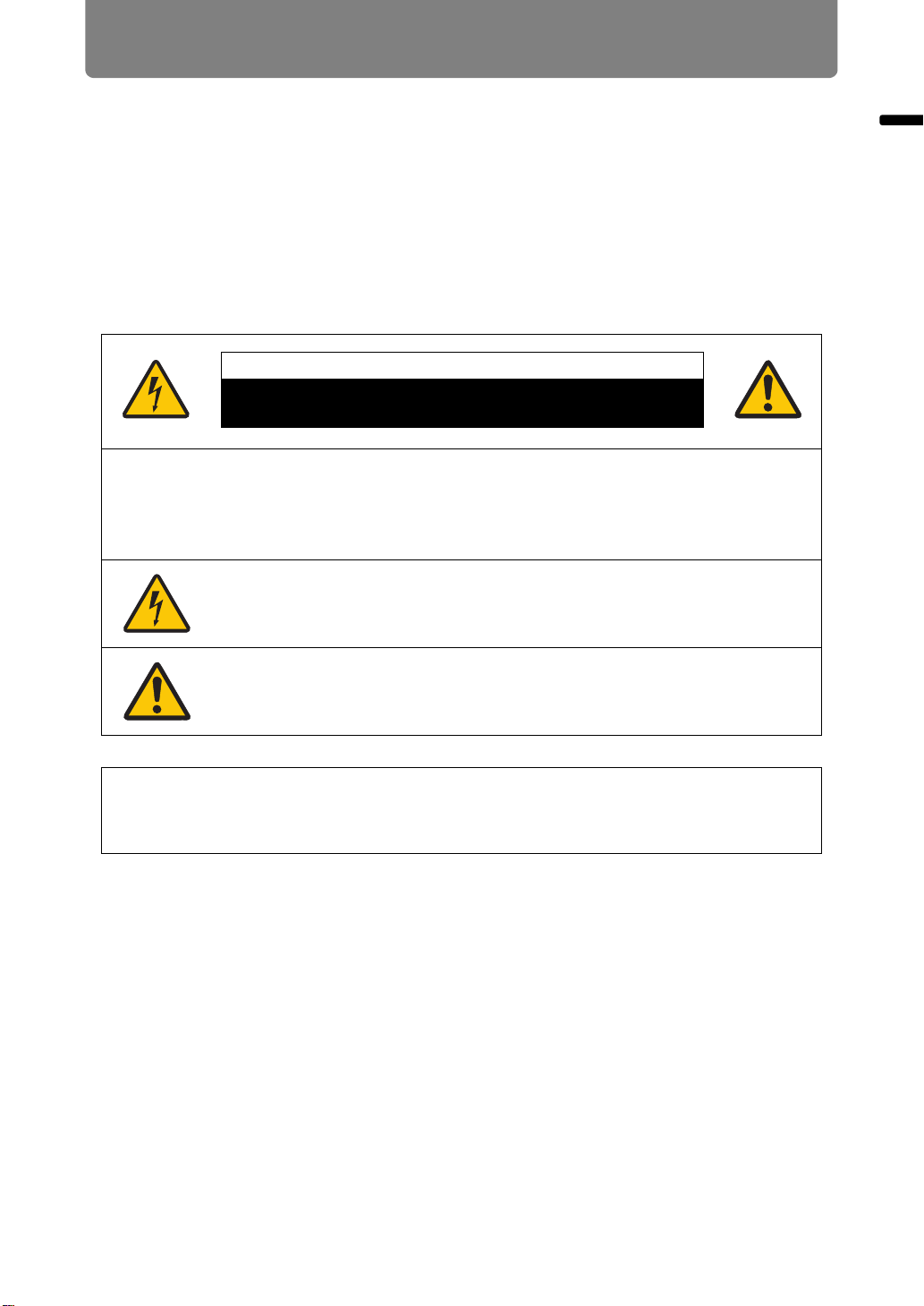
Safety Symbols in this Manual
This section describes the safety symbols used in this manual. Important projector
safety information is identified by the following symbols. Always observe the safety
information by these symbols.
Denotes the risk of death or serious injury from improper
handling if the information is not observed. To ensure safe use,
always observe this information.
Denotes the risk of injury from improper handling if the
information is not observed. To ensure safe use, always observe
this information.
Denotes the risk of electric shock from improper handling if the
information is not observed. To ensure safe use, always observe
this information.
Denotes the risk of burns from improper handling if the
information is not observed. To ensure safe use, always observe
this information.
Denotes prohibited actions.
Safety Instructions
Denotes required actions or information that must be observed.
13
Page 16
Safety Instructions
Precautions for Use
As this section contains important safety-related information, be sure to read the
following carefully beforehand in order to use your projector correctly and safely.
During installation, keep the projector plug easily accessible so that the projector can be
unplugged immediately if necessary, or keep a circuit breaker within reach.
If the following situations occur, turn the power off, remove the power plug from the
power outlet and contact the Canon Customer Support Center. Failure to do so could
cause a fire or result in an electric shock.
• If smoke is emitted
• If an unusual smell or noise is emitted
• If water or other liquid has entered the projector
• If metal or any other foreign material has entered the projector
• If the projector is knocked over or dropped and the cabinet is
damaged
Pay attention to the following points regarding the power source, power plug and
handling of the connector. Failure to do so may cause a fire or electric shock.
• Do not place any objects on the power cord and do not allow it to
become trapped under the projector.
• Do not cover the power cord with a carpet.
• Do not modify or excessively bend, twist, pull, wind, or bundle the
power cord.
• Keep the power cord away from heaters and other sources of
heat.
• Do not use a damaged power cord. If the power cord is
damaged, purchase a replacement from your dealer.
• The power cord included with this projector is for use exclusively
with this product. Do not use this cord for other products.
14
Page 17
Safety Instructions
Pay attention to the following points regarding the power source, power plug and
handling of the connector. Failure to do so may cause a fire or electric shock.
•
Do not use any power source with a voltage other than the voltage
indicated (AC 100–240 V).
• Do not pull the power cord and be sure to hold the power plug or
connector when removing. Incorrect handling may damage the
power cord.
• Do not insert any metal objects into the contact parts of the
power plug or connector.
• Do not remove the power plug or connector with wet hands.
• Insert the power plug and connector securely up to the base.
Additionally, do not use a damaged power plug or an outlet that is
loose.
• When using an extension cord, do not exceed the cord’s rated
capacity.
• Periodically inspect the power plug and outlet and remove any
dust or dirt from between the plug and the outlet.
Safety Instructions
Installation and Handling Precautions
Pay attention to the following points regarding installation and handling of the projector.
Failure to do so may cause a fire, electric shock or personal injury.
• Do not use the projector where it might get wet, such as outdoors
or by bathtubs or showers.
• Do not place containers containing a liquid on top of the
projector.
• Do not touch the projector itself, the power cord, or the cable if
lightening strikes.
• Do not move the projector until you have switched off the power,
removed the power plug from the power outlet and unplugged
any other cables.
• Unplug the projector before cleaning or maintenance.
• Before you attach or replace a lens unit, be sure to unplug the
power plug of the projector from the power outlet.
15
Page 18

Safety Instructions
RISK GROUP 3 (RG3) label
16
Page 19
Safety Instructions
Pay attention to the following points regarding installation and handling of the projector.
Failure to do so may cause a fire, electric shock or personal injury.
• Do not remove the cabinet from the projector or disassemble it. The interior
of the projector contains high-voltage components as well as parts that are
hot. If inspection, maintenance or repair is required, contact the Canon
Customer Support Center.
• Do not disassemble or modify the projector (including consumable parts) or
the remote control.
• Do not look directly into the exhaust vents during use.
• Do not insert any object into vents in the projector, such as the air intake vent
or exhaust vents.
• Do not place a pressurized can in front of the exhaust vents. The pressure of
the contents of the can may increase due to heat from the exhaust vents and
this could result in an explosion.
• When cleaning off dust or dirt from projector parts such as the lens or filter,
never use any spray that is flammable. Internal parts that become hot may
ignite and cause a fire.
• Light from the projector is classified as
Risk Group 3 (RG3) according to
IEC 62471:2006.
• Possibly hazardous optical radiation emitted
from this product. Do not look at operating lamp. Eye injury may result. Pay
particular attention to prevent small children from doing so.
• When setting the projector on a high surface for projection, be sure the
surface is flat and stable.
• Do not use the projector on a soft surface such as carpet or sponge mat, etc.
Doing so could cause heat to build up inside the projector and this could
result in a fire.
• For ceiling mounting precautions, refer to the installation manual included
with the ceiling mount (sold separately).
Safety Instructions
• When hanging the projector from a ceiling, put the projector down on the
floor or a workbench before attaching or replacing the lens unit. Failure to do
so could result in parts falling off the projector and may cause an accident or
personal injury.
Precautions on the Lamp
This projector uses a high-pressure mercury lamp, which must be handled carefully and
correctly as described below.
The mercury lamp has the following characteristics.
• The lamp will gradually become darker over time.
• Impact, abrasion, or use of worn-out lamps may cause lamps to rupture (accompanied
by a loud noise) or burn out.
• Lamps are more likely to rupture after the lamp replacement message is displayed (see
“Replacing the Lamp” (P173)). Replace the lamp with a new one as soon as possible.
• Useful life of lamps varies widely from lamp to lamp and depending on the environment
of use. Some lamps may fail or rupture soon after they are first used.
17
Page 20
Safety Instructions
Note the following precautions during lamp replacement or when a lamp has ruptured.
Failure to do so could result in an electric shock, personal injury or burns.
• Before replacing the lamp, always unplug the projector and wait at least one
hour.
• If the lamp ruptures, dust and gas (containing mercury vapor) may come out
of the exhaust vents. If this happens, immediately open the windows and
doors to provide ventilation to the room. Ruptured lamps may scatter shards
of glass inside the projector. Contact the qualified technician or Canon
Customer Support Center for cleaning and inspection of the projector interior
and lamp replacement.
• If you accidentally inhale gas from the lamp or get any pieces in your eyes or
mouth, consult a doctor immediately.
Note the following precautions when replacing lamps that stop working. Failure to do so
could result in personal injury.
• If illumination suddenly stops, either when you turn the projector on or after it
has been on for a while, the lamp may have ruptured. In this case, never
attempt to replace the lamp by yourself. Always request service from the
Canon Customer Support Center.
• With ceiling-mounted projectors, the lamp may fall out when you open the
lamp cover, or during replacement. During replacement, stand to the side of
the lamp cover, not directly under it.
Precautions for the Batteries of the Remote Control
Pay attention to the following points regarding handling of batteries. Failing to do so
could result in a fire or personal injury.
•
Do not heat, short circuit or disassemble the batteries, or place them in a fire.
• Do not attempt to recharge the batteries that are included with the remote
control.
• Remove the batteries when they are flat or when the remote control will not
be used for a long period of time.
• When replacing the batteries, replace both at the same time. Also, do not
use two batteries of a different type at the same time.
• Insert the batteries with the + and - terminals in the correct directions.
• If any liquid from inside the batteries leaks out and contacts your skin, be
sure to wash the liquid off thoroughly.
18
Page 21
Safety Instructions
Pay attention to the following points regarding installation and handling of the projector.
• If the projector will not be used for a long period of time, be sure
to remove the power plug from the power outlet to ensure safety.
Failure to do so presents a risk of fire if dust accumulates on the
plug or outlet.
• Parts of the cabinet around and above the exhaust vents may
become hot during projection. Touching these areas during
operation could cause burns to the hands. Pay particular
attention in preventing young children from touching these parts.
Additionally, do not place any metal objects around or above the
exhaust vents. Due to the heat from the projector, doing so could
cause an accident or personal injury.
• Do not place the projector where it may be exposed to oily smoke
or steam, such as near kitchen counters or humidifiers. Doing so
may cause fire or electric shock.
• Do not place any heavy objects on top of the projector or sit /
stand on it. Pay particular attention to prevent small children from
doing so. The projector may be knocked over and this could
result in damage or a personal injury.
• Do not place the projector on an unstable or slanted surface.
Doing so may cause the projector to fall or be knocked over and
could result in a personal injury.
• Do not place any objects in front of the lens
during projection. Doing so could cause a fire.
• Presenters in front of the projector should
stand where the light does not seem too bright,
and where their shadow does not fall on the screen.
• The projector is provided with a lens shift function to move the
lens up, down, left, and right using the motor. Do not touch the
lens while it is moving. Touching the lens when it is moving may
result in personal injury.
• Before replacing the lens unit, wait at least one hour after the
projector is turned off to allow the projector to cool thoroughly.
Failure to do so could result in a burn or injury.
Safety Instructions
When handling the lamp, pay attention to the following points.
• Lamps are more likely to rupture once the lamp replacement
message has been displayed. Replace the lamp with a new one
as soon as possible.
• Be sure not to handle the lamp immediately after it has been
used. Be sure to switch off the power and wait for approximately
1 hour for the lamp and the projector to cool down sufficiently.
Failure to do so could result in a burn or personal injury due to
heat from the lamp or projector.
• Be prepared by keeping a spare lamp.
• Dispose of used mercury lamps in accordance with local
regulations.
19
Page 22
For Safe Use
Pay attention to the following points when carrying or transporting the projector.
• This projector is a precision instrument. Do not knock it over or subject it to
impacts.
• When carrying or holding up the projector after attaching the lens unit, be
sure not to hold the lens. Doing so may cause damage to the lens unit.
• Protection of the projector cannot be guaranteed if used packaging or shockabsorbent materials are reused. Fragments from shock-absorbent material
may also enter the interior of the projector which could cause a malfunction.
• If transportation is necessary, the lens unit should be removed before
transporting the projector. If the projector is subjected to excessive impacts
during transportation, the lens unit may be damaged.
• Disconnect the cables connected to the projector. Carrying the projector
while the cables are attached may cause an accident.
• Retract the adjustable feet before moving the projector. Leaving the feet
extended may cause damage.
• Do not touch the lens with bare hands. Doing so may result in deterioration
of image quality.
20
Page 23
Pay attention to the following points when installing or using the projector.
• Be careful of condensation.
If the projector is abruptly taken to a warmer location, or if the room
temperature rises abruptly, moisture in the air may condense on the lens and
mirror, causing the image to become blurred.
• Do not install the projector in a location where the temperature is high or low.
Doing so may cause a malfunction. Ranges for the environment of use and
storage are as follows.
• Environment of use: 0°C (32°F) to 40°C (104°F), up to 85% RH
• Storage temperature: -30°C (-22°F) to 60°C (140°F)
• When using the projector at altitudes above 2,300 m (7,545.8'), or when
projecting upward or downward:
Adjust projector installation settings from the menu (P108). Failure to adjust
the settings may shorten the lamp life or damage the lamp.
• Do not install the projector facing the wrong direction. Install the projector so
that it is not tilted left or right by more than 10°. (P25)
• Do not block the air intake or exhaust vents. Blocking the vents may trap
heat inside the projector, which may shorten the useful life of optical
components or other parts and damage the projector.
• Install the projector leaving at least 50 cm (1.6') between air intake/exhaust
vents and walls. Failure to do so may trap heat inside the projector and
damage it.
• Do not place any objects on top of the projector that may change shape or
color due to heat.
• Do not install the projector in a location that is damp, or where there is a lot
of dust, oily smoke or tobacco smoke. Doing so could cause contamination
of optical components such as the lens and the mirror and may result in
deterioration of image quality.
• Do not install the projector near high-voltage electrical power lines or an
electrical power source.
• Clean the air filter regularly. (P171) Dust that accumulates inside over long
periods without cleaning may eventually damage the projector or affect
picture quality.
For Safe Use
For Safe Use
21
Page 24
Before Installation
Precautions When Carrying/Shipping the Projector
Prepare the projector as described below before carrying it.
• Disconnect the cables connected to the projector. Carrying the
projector with the cables attached may cause an accident.
• Retract the adjustable feet before moving the projector. Leaving
the feet extended may cause damage.
• Do not subject the projector to strong impacts or vibrations.
Precautions for Installation
Be sure to read “Safety Instructions” and “For Safe Use” (P7 – P21). Also
take the following precautions during installation.
• Do not strike the projector or subject it to impact. Doing so may
cause a malfunction.
• Do not stand the projector vertically, lean it against another
object, or otherwise place it in an unstable state. The projector
may be damaged if it tips over.
■ Do Not Use in the Following Environments
• Locations with excessive humidity, dust, oily smoke or tobacco
smoke
Adhesion to the lens, mirrors or other optical parts may reduce image
quality.
• Near high-voltage power lines or sources of electrical power
This may cause malfunction.
• On soft surfaces such as carpets or cushioned mats
This may cause a fire or damage the projector.
• Locations with excessive temperature or humidity
This may damage the projector. Acceptable ranges for operating and
storage temperature and humidity are as follows.
* Operating temperature and humidity applies to when the projector
is projecting or in standby mode.
Operating temperature Operating humidity Storage temperature
0°C (32°F) – 40°C (104°F)
Up to 85%
-30°C (-22°F) – 60°C (140°F)
22
Page 25
■ Do Not Touch the Lens with Bare Hands
Before Installation
• Do not touch the lens with bare hands. Any smudges or
fingerprints on the lens may affect image quality.
■ Allow a 30 Min. Warm Up before Focus Adjustment (P59), if Possible
The focus position may not stabilize immediately after startup, due to lamp heat.
When adjusting focus, it is also helpful to use the test pattern (10) (P115, P187).
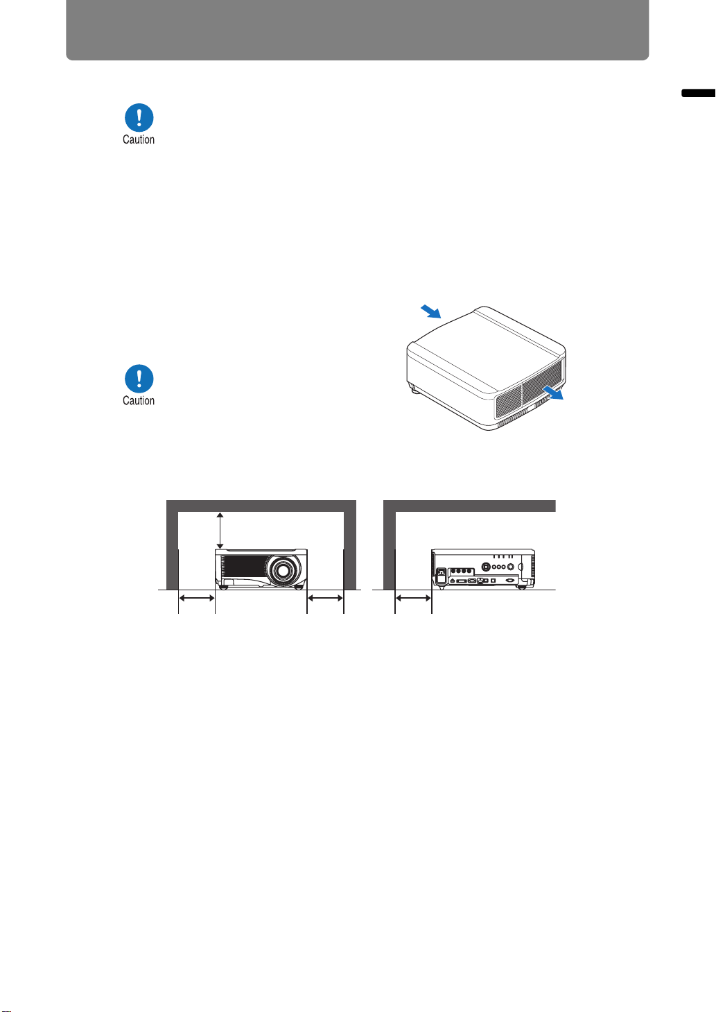
■ Install at a Sufficient Distance from Walls and Other Obstructions
If the air intake or exhaust
vent is blocked, heat will
accumulate inside the
projector, possibly resulting in
a shortened projector lifetime
or a malfunction.
Similarly, do not install in
narrow, enclosed spaces with
poor ventilation. Install in a
well-ventilated location.
Ensure a minimum clearance of 50 cm (1.6 ft.) above, on both
sides, and behind the projector, as shown below.
Air intake vent
Warmed
airflow
Exhaust vent
Before Installation
At least
50 cm (1.6')
50cmà»è„
At least
50 cm (1.6')
At least
50 cm (1.6')
At least
50 cm (1.6')
■ Be Careful of Condensation
If the temperature of the room rises suddenly, moisture in the air may condense on
the projector lens and mirror, causing the image to become blurred. Wait until the
condensation has evaporated for the image projected to return to normal.
■ At Altitudes above 2,300 m (7,545.8'), Adjust the Settings
Projector settings must be adjusted when using the projector at altitudes of 2,300 m
(7,545.8') or higher. Specifically, refer to instructions for [Fan mode] (P108) in the
[Install settings] menu.
23
Page 26
Before Installation
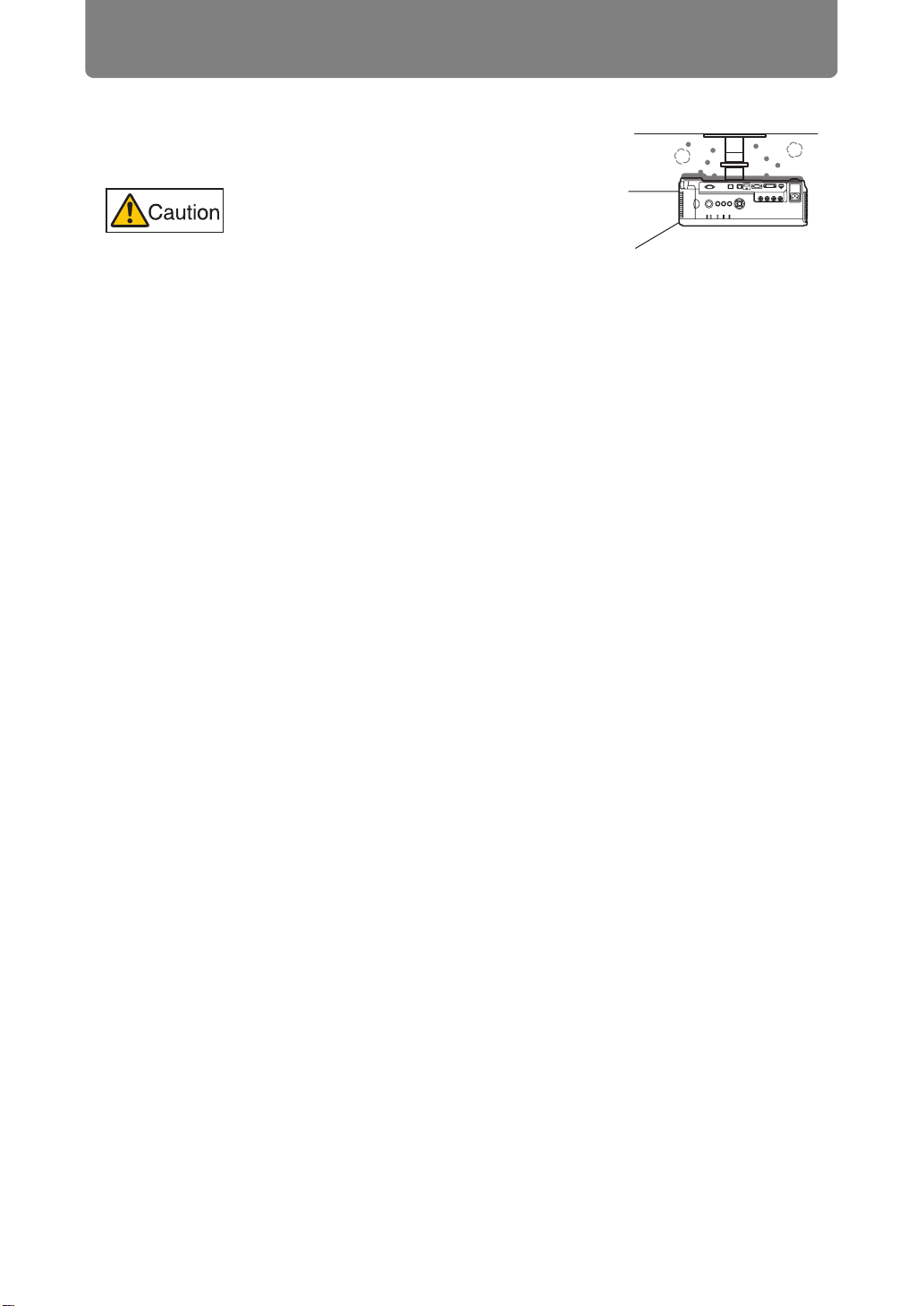
■ When Using Mounted on the Ceiling
When the projector is used mounted on the
ceiling or installed in a high location, it is
necessary to periodically clean the air
intake and exhaust vents, and the area
around the air filter. Dust that accumulates
in intake or exhaust vents may impair
ventilation, raising the temperature inside
and posing a risk of damage or fire. Use a
vacuum cleaner or similar means to
remove dust from the intake vent and
exhaust vent.
24
Page 27
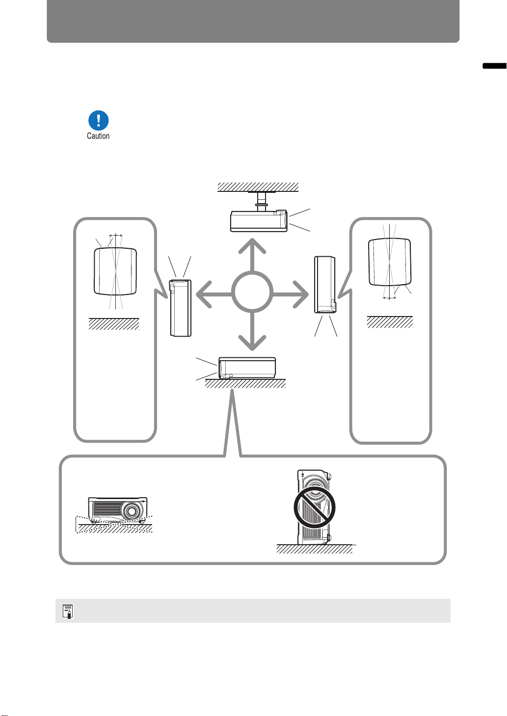
■ Install Facing in the Correct Direction
Before Installation
• The projector can be installed facing any direction, as shown
below. However, projection upward or downward may shorten the
useful life of the lamp. [Install settings] of the projector must also
be adjusted.
• For upward or downward projection, refer to instructions for
[Vertical projection] (P108) in the [Install settings] menu.
• Do not attempt to install the projector for upward or downward
projection by yourself. Always request installation by a qualified
technician or the Canon Customer Support Center.
10° 10°
Upward
projection:
Inclination of the
projector should
be no more than
10° from the
vertical axis.*
10° 10°
Downward
projection:
Inclination of the
projector should
be no more than
10° from the
vertical axis.
*
Before Installation
10°
10°
If installing the projector
on the floor or hanging
from the ceiling, the left /
right inclination of the
projector should be no
more than 10°.*
Do not use the
projector standing
on its side.
damage the lamp.*
* Failure to do so may damage the lamp.
There are no options for installing the projector other than the ceiling attachment.
25
This may
Page 28

Before Installation
Copyright Notice
Please note that enlarging or reducing the size of an image for commercial
purposes or public presentation may infringe on the legally protected copyright
or the copyright holder of the original material.
Ensure Network Security
Take measures to ensure network security. Note that Canon is not liable in any
way for direct or indirect loss from network security incidents, such as
unauthorized access.
Before using the projector, configure the appropriate projector, computer, and
network security settings.
Install the projector in a network protected by a firewall or other security
measures. Do not connect it directly to the Internet.
About Trademarks
• Ethernet is a registered trademark of Xerox Corporation.
• Microsoft, Windows, Windows Vista, Windows 7, Windows 8, Windows 8.1
and Windows 10 are registered trademarks or trademarks of Microsoft
Corporation in the United States and / or other countries.
• Mac, Mac OS and Macintosh are trademarks of Apple Inc., registered in the
United States and / or other countries.
• HDMI, the HDMI logo and High-Definition Multimedia Interface are
trademarks or registered trademarks of HDMI Licensing, LLC.
• PJLink is a registered trademark of JBMIA and pending trademark in some
countries.
• PJLink is a registered trademark, or an application has been submitted for
trademark, in Japan, the United States and / or other countries or regions.
• AMX is a trademark of AMX Corporation.
• Crestron®, Crestron RoomView®, and Crestron Connected™ are registered
trademarks of Crestron Electronics, Inc.
• HDBaseT™ and the HDBaseT Alliance logo are trademarks of the HDBaseT
Alliance.
• All other trademarks are the property of their respective owners.
26
Page 29

Open Source Software
The product contains Open Source Software modules. For details, refer to the thirdparty software license file “Third-Party Software” in the License folder of the user’s
manual CD-ROM. Each module’s license conditions are also available in the same
folder.
■ Software under the GNU General Public License Version 2
Contained programs are free software; you can redistribute them and/or modify
them under the terms of the GNU General Public License attached to each copy of
the program.
Each program is distributed in the hope that it will be useful, but WITHOUT ANY
WARRANTY; without even the implied warranty of MERCHANTABILITY or
FITNESS FOR A PARTICULAR PURPOSE. Please see “NO WARRANTY” and
“NO SUPPORT” stated below. For more detail, please see full text of the GNU
General Public License.
NO WARRANTY
BECAUSE THE PROGRAM IS LICENSED FREE OF CHARGE, THERE IS NO
WARRANTY FOR THE PROGRAM, TO THE EXTENT PERMITTED BY
APPLICABLE LAW. EXCEPT WHEN OTHERWISE STATED IN WRITING THE
COPYRIGHT HOLDERS AND/OR OTHER PARTIES PROVIDE THE PROGRAM
“AS IS” WITHOUT WARRANTY OF ANY KIND, EITHER EXPRESSED OR
IMPLIED, INCLUDING, BUT NOT LIMITED TO, THE IMPLIED WARRANTIES OF
MERCHANTABILITY AND FITNESS FOR A PARTICULAR PURPOSE. THE
ENTIRE RISK AS TO THE QUALITY AND PERFORMANCE OF THE PROGRAM
IS WITH YOU. SHOULD THE PROGRAM PROVE DEFECTIVE, YOU ASSUME
THE COST OF ALL NECESSARY SERVICING, REPAIR OR CORRECTION.
Open Source Software
IN NO EVENT UNLESS REQUIRED BY APPLICABLE LAW OR AGREED TO IN
WRITING WILL ANY COPYRIGHT HOLDER, OR ANY OTHER PARTY WHO MAY
MODIFY AND/OR REDISTRIBUTE THE PROGRAM AS PERMITTED ABOVE, BE
LIABLE TO YOU FOR DAMAGES, INCLUDING ANY GENERAL, SPECIAL,
INCIDENTAL OR CONSEQUENTIAL DAMAGES ARISING OUT OF THE USE OR
INABILITY TO USE THE PROGRAM (INCLUDING BUT NOT LIMITED TO LOSS
OF DATA OR DATA BEING RENDERED INACCURATE OR LOSSES SUSTAINED
BY YOU OR THIRD PARTIES OR A FAILURE OF THE PROGRAM TO OPERATE
WITH ANY OTHER PROGRAMS), EVEN IF SUCH HOLDER OR OTHER PARTY
HAS BEEN ADVISED OF THE POSSIBILITY OF SUCH DAMAGES.
NO SUPPORT
Canon Inc., and all its subsidiaries or its dealers do not make any support service
regarding the source code. Canon Inc., and all its subsidiaries or its dealers shall
not respond to any questions or enquiries, from you or any other customers,
regarding the source code.
27
Page 30
Before Use
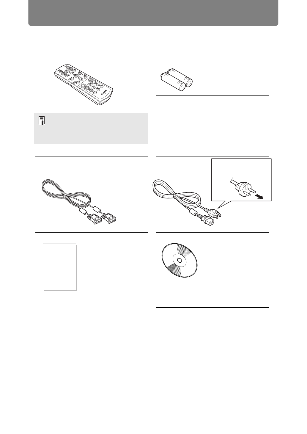
Included Accessories
Before use, make sure the following items are included in the package.
• Remote control • Batteries for the remote control
(AAA size x2)
(part No.: RS-RC04)
Optional remote controls are also
available (RS-RC05). The RS-RC05
can also be used as a wired remote.
(P38)
• Computer cable (1.8 m / 5.9')
(mini D-sub 15-pin / mini D-sub 15-pin)
• Important Information
• Power cord
(1.8 m / 5.9')
For the U.S.A.
and Canada
• User’s Manual (CD-ROM)
• Warranty Card
For Continental
Europe
28
Page 31

Part Names
Projector
Before Use
Power cord connector (P52)
Terminals and
connectors
Anti-theft lock hole
An anti-theft wire cable (not included) can be connected.
■ Rear Side
Side control (P30)
Lens unit (sold separately)
Infrared remote receiver
(P38)
Air filter frame (P172)
Exhaust vent
Before Use
Air intake vent
Do not block the air intake.
Doing so may cause a
malfunction.
Do not block the air exhaust.
Doing so may cause a
malfunction.
Lamp cover
Infrared remote receiver (P38)
29
Page 32

Before Use
■ Bottom Side
Adjustable feet (P40)
Side Control
Bolt holes for installation of
ceiling attachment
(6)
(1) POWER button (P53, P71)
Turns the projector on or off.
(2) MENU button (P78)
Displays a menu on the screen.
(3) LENS button
Each time the button is pressed,
the screen changes to focus
adjustment (P59), zoom (image
size) adjustment (P60), or lens shift
(image position) adjustment (P61).
To adjust, use the [ ] / [ ] or the
[ ] / [ ] buttons.
(1)
(3)
(2)(4)(5)
(4) INPUT button (P56)
Switches the input signal.
(5) Pointer / VOL buttons (P79)
Up, down, left, or right in menu
navigation or other operations.
Adjust the sound volume.
[ ] VOL+ button: Increases the
volume.
[ ] VOL– button: Decreases the
volume.
Selects the upper, lower, left or
right item in the menu.
(6) OK button (P79)
Determines the item selected from
the menu.
30
Page 33

LED Indicators
The projector status is shown by the LED indicators (off / lit / flashing).
• POWER ON (green) : Lights up or flashes under normal
conditions when the power is on.
• STAND BY (red) : Lights up or flashes during standby or
when the projector is shut down.
• WARNING (red) : Lights up or flashes when an error
occurs.
• LAMP (orange) : Lights up or flashes when a problem
occurs with the lamp or lamp cover.
• TEMP (red) : Lights up or flashes when the internal
temperature is high.
Before Use
Before Use
31
Page 34

Before Use
■ LED Indicator Displays
The LED indicators flash or illuminate to indicate the operating status of the
projector.
Legend: Example of when the POWER ON indicator is on; : Off : Lit : Flashing
LED indicator
POWER
ON
(green)
STAND
BY
(red)
WARNING
(red)
LAMP
(orange)
TEMP
(red)
Operating status
Not plugged in.
In standby mode.
Power is on.
Transitioning from standby mode to
power on.
Cooling down while transitioning from
power on to standby mode or power
management mode.
In power management mode, with the
lamp off.
Nearly time to replace the lamp (in
standby mode).
Nearly time to replace the lamp (during
projecting).
Internal temperature is high (in standby
mode).
Internal temperature is high (during
projecting).
A lamp error has occurred.
A temperature error has occurred.
The lamp cover is open.
Another error has occurred.
A flashing LAMP indicator means that it is almost time to replace
the lamp. Prepare a replacement lamp.
32
Page 35

Input Terminal
Before Use
(1) (2)
(4)
(5) (6) (7) (8) (9) (10)
(3)
(1) Terminal for wired remote control (REMOTE) (P38)
This terminal is used to connect the optional remote control (RS-RC05) using a
cable.
(2) AUDIO IN terminal (AUDIO IN) (P49, P50, P51)
Terminals for audio input. Audio supplied to these terminals is played through
the internal speaker when you select [Audio in] as the source audio terminal
for the selected source video. (P119)
(3) AUDIO OUT terminal (AUDIO OUT) (P49, P50, P51)
Outputs the audio to external AV equipment. This outputs the audio signal that
corresponds to the projected image signal.
(4) USB port (P157)
Connects a USB flash drive. Used for projection of images on a USB flash
drive, or for firmware updates.
Before Use
(5) DVI-I terminal ( DVI-I) (P49)
Connects the external monitor output from a computer.
Receives digital PC signal (Digital PC).
A VGA-DVI-I cable can also be used to receive analog computer signals
(Analog PC-1).
(6) ANALOG PC-2 / COMPONENT input terminal ( / COMPONENT)
(P50, P51)
Receives the analog PC signal (Analog PC-2).
A component cable can be used to receive the component image signal
(Component).
(7) HDMI terminal (HDMI) (P50, P51)
Receives digital video signals (HDMI).
Carries both video and audio signals across a single cable.
(8) LAN port (P127)
Connects the LAN cable (shielded twisted pair).
Used to connect the projector to a network.
(9) HDBaseT terminal (P50, P51, P127)
Receives HDBaseT input including digital video and audio signals.
A single LAN cable (shielded twisted pair) can be used for both video and
audio input.
This port can also be used to connect the projector to a network.
33
Page 36

Before Use
(10) Service port (CONTROL) (P195)
Used to control the projector with user commands (P196 – P197).
34
Page 37

Before Use
Remote Control
The projector can be operated using buttons on the remote control or the side
control on the projector.
(1)
(2)
(3)
(4)
(5)
(8)
(3) ASPECT button (P65, P91)
Changes the aspect ratio mode.
(4) D.SHIFT/KEYSTONE button (P67)
Corrects keystone distortion.
The [Keystone] setting enables both
horizontal/vertical keystone correction
(by adjusting top/bottom/left/right
length) and corner correction.
• Moves the image up, down, left, or
right when the screen aspect setting
is [16:9 D. image shift] or [4:3 D.
image shift] is selected. (P64, P65)
• To move the image, use the [ ] / [ ]
or the [ ] / [ ] buttons.
(5) D.ZOOM button (P75)
Zooms the image in or out digitally.
[ ] button: Zooms the image in (up to
12x).
[ ] button: Zooms the image out (1x
minimum).
[ ] / [ ] / [ ] / [ ] buttons:
Move the zoom-in location.
Before Use
(6)
(7)
(1) POWER button (P53, P71)
Turns the projector on or off.
(2) FOCUS button (P59)
Adjusts focusing.
[ ] / [ ] buttons:
Moves the focus position further away.
[ ] / [ ] buttons:
Moves the focus position nearer.
(6) FREEZE button (P72)
Freezes the projected image.
(7) IMAGE button (P70)
Switches the image mode (image
quality).
(8) INPUT button (P56)
Switches the input signal.
35
Page 38

Before Use
(12) OK button (P79)
Determines the item selected from the
menu.
(9)
(10)
(11)
(12)
(13)
(14)
(15)
(16)
(17)
(18)
(13) Pointer buttons (P79)
Selects the upper, lower, left or right
item in the menu. Also used to assign a
channel to the remote control.
(14) MENU button (P78)
Displays a menu on the screen. Also
used to assign a channel to the remote
control. (P119)
(15) VOL button (P74)
Adjusts the sound volume.
[+] button: Increases the volume.
[–] button: Decreases the volume.
(16) P-TIMER button
Cannot be used on this projector.
(17) MUTE button (P74)
Mutes the sound.
(18) BLANK button (P72)
Temporarily blacks out the image.
(19)
(20)
(9) LENS-SHIFT button (P61)
Moves the lens up, down, left, or right.
[ ] / [ ] / [ ] / [ ] buttons:
Moves the image.
(10) ZOOM button (P60)
Adjusts the image size.
[ ] / [ ] buttons:
Increase the image size.
[ ] / [ ] buttons:
Decrease the image size.
(11) AUTO PC button (P58)
Adjusts tracking etc. automatically in
accordance with the signal from a computer
when the analog PC input is selected.
(19) LAMP button (P102)
Displays the power saver settings
screen, where you can adjust the lamp
mode (Full power / Power saver)
(P102), set the power management
(P121) and specify the network standby
settings (P131).
(20) GAMMA button (P98)
Adjusts the gamma of the image.
[ ] button:
Corrects dark parts of the image so that
they are easier to see.
[ ] button:
Corrects bright parts of the image so
that they are easier to see.
36
Page 39

Preparing the Remote Control
■ Installing Remote Control Batteries
Before Use
1 Open the battery
compartment lid.
Slide the lid while
pressing it down.
• If buttons on the remote control are inoperative when you attempt to operate the
projector, replace the batteries with new ones.
• Do not drop the remote control or subject it to impact.
• Do not spill any liquids on the remote control. Doing so may cause a malfunction.
Pay attention to the following points when handling the batteries.
Failing to do so could result in a fire or personal injury.
• Do not heat, short circuit or disassemble the batteries, or place
them in a fire.
• Do not attempt to recharge the batteries that are included with the
remote control.
2 Insert batteries.
Insert 2 new AAA
batteries in the
compartment with the
+ and – terminals
positioned correctly.
3 Close the
compartment lid.
Slide the lid until you
hear a click to
securely close it.
Before Use
• Remove the batteries when they are flat or when the remote control
will not be used for a long period of time.
• When replacing the batteries, replace both at the same time. Also,
do not use two batteries of a different type at the same time.
• Insert the batteries with the + and - terminals in the correct
directions.
• If any liquid from inside the batteries leaks out and contacts your
skin, be sure to wash the liquid off thoroughly.
37
Page 40

Before Use
■ Remote Control Operating Range
The remote control is an infrared type. Point it at the infrared remote receiver on the
front or rear of the projector to operate it.
25°
8 m (26.3')
25°
8 m (26.3')
25°
25°
• Use the remote control no further than approximately 8 m (26.3') from the projector.
• Use the remote control within an angle of 25° in any direction from directly in front of the
infrared remote receiver.
• The remote control may be inoperative if there is an obstacle between the remote
control and the projector or the infrared remote receiver on the projector is exposed to
direct sunlight or strong light of lighting equipment.
• When you use 2 or more projectors at the same time, you can change the channel
settings to prevent the 2 remote controls from interfering with each other. (P119)
■ Using an Optional Wired Remote (RS-RC05)
To use a wired remote control with the projector, use the RS-RC05, sold separately.
Use a cable with a ø3.5 mm stereo mini jack (not included).
Remote control
(RS-RC05)
Terminal for wired
remote control
ø3.5 mm stereo mini jack
cable (not included)
• Infrared operations cannot be performed if a cable is connected to the projector or the
remote control.
• Use a cable with a ø3.5 mm stereo mini jack (not included) with a length of 30 m (98.4')
or less.
38
Page 41

Safety Instructions
Before Use
Basic Guide
Installation Procedure
Basic Guide
Connection Procedure
Projection Procedure
Convenient Features
Using Menus
Advanced Guide
Menu Configuration
Menu Description
39
Advanced Projection
Other Information
Maintenance
Product Specifications
Troubleshooting
Page 42

Installation Procedure
Before setting up the projector, be sure to read “Before Installation” (P22).
Setting Up the Projector
■ Positioning the Projector in Front of the Screen
Place the projector in front of the screen.
• To avoid keystone distortion, install the
projector so that it is at right angles to the
screen.
• The screen must not be exposed to direct
sunlight or light from lighting equipment. In
a bright room, it is recommended that
lights be turned off, curtains be drawn, and
other steps taken to make the screen
easier to see.
Optical axis
Screen
■ Floor Installation
To adjust the projection position when the projector is installed on the floor, use the
lens shift function (P47, P61) to adjust up / down / left / right. You can also use the
adjustable feet to incline the projector upward by up to 6°.
For information about the relationship between screen size and projection distance,
refer to page 43.
Lens shift
Adjustable feet
■ Installation Tilted Upward
To correct keystone distortion when the projector is tilted upward (using adjustable
feet, for example), perform keystone correction (P67) or corner adjustment (P68).
40
Page 43

Installation Procedure
■ Installation on High Surfaces
For projection from a shelf or other high surface, the projector can be installed
upside-down and the projected image inverted.
When setting the projector on a
high surface for projection, be sure
the surface is flat and stable.
Failure to do so poses a risk of the
projector falling and causing
accidents or injury.
■ Ceiling Mounting or Rear Projection
You can mount the projector on the ceiling (ceiling mounting) with it turned upside
down or place it behind the screen (rear projection) if you use a translucent screen.
Basic Guide Installation Procedure
Ceiling mounting Rear projection
Make sure to use the optional ceiling attachment. For the ceiling attachment, refer
to “Option” (P207). For details, refer to the assembly and installation manual
provided with the ceiling attachment.
41
Page 44

Installation Procedure
Mounting the Projector on the Ceiling
You can mount the projector on the ceiling.
The ceiling attachment (part No.: RS-CL11)
is required in order to mount the projector on
the ceiling. Depending on the installation
environment, an extension pipe
(part No.: RS-CL08 or RS-CL09) may also
be required. Contact the Canon Customer
Support Center for more detailed
information.
• Make sure to use the optional ceiling attachment.
• You should never install the ceiling attachment by yourself.
If you mount the projector on the ceiling, you have to invert the projected image by
selecting [Image flip H/V] from the menu. (P105)
42
Page 45

Installation Procedure
Relationship Between Image Size and Projecting Distance
The projected image size is determined by the distance between the projector and
the screen (projection distance) as well as the zoom. Refer to the following table
and decide the distance between the projector and screen.
16:9 / 16:10
Screen size
Height
(diagonal)
Width
• H1 and H2 are the distances when lens shift is the default value below.
• Standard Zoom Lens / Long Zoom Lens / Ultra Long Zoom Lens / Wide Zoom Lens:
+50% (up / down), 0% (left / right)
Short Fixed Lens: 0% (up / down / left / right)
4:3
Width
WUX6500
Image size (cm)
Diagonal
Lens unit
Standard
Zoom Lens
RS-IL01ST
when
16:10
40 86 54 89 50 81 61
60 129 81 133 75 122 91
80 172 108 177 100 163 122
100 215 135 221 125 203 152
150 323 202 332 187 305 229
200 431 269 443 249 406 305
250 538 337 553 311 508 381
300 646 404 664 374 610 457
350 754 471 775 436 711 533
400 862 538 886 498 813 610
450 969 606 996 560 914 686
500 1077 673 1107 623 1016 762
550 1185 740 1218 685 1118 838
600 1292 808 1328 747 1219 914
16:10 16:9 4:3 16:10
Width Height Width Height Width Height
Optical axis when projection is
perpendicular to screen
Height
Projection
distance
m (feet)
Wide
limit
1.3
(4.3)
1.9
(6.2)
2.6
(8.5)
3.2
(10.5)
4.8
(15.7)
6.4
(21.0)
8.0
(26.2)
9.6
(31.5)
11. 3
(37.1)
12.9
(42.3)
14.5
(47.6)
16.1
(52.8)
17.7
(58.1)
19.3
(63.3)
Tele
limit
1.9
(6.2)
2.9
(9.5)
3.9
(12.8)
4.8
(15.7)
7.2
(23.6)
9.6
(31.5)
12.1
(39.7)
14.5
(47.6)
16.9
(55.4)
19.3
(63.3)
21.7
(71.2)
24.1
(79.1)
26.6
(87.3)
29.0
(95.1)
H1
H2
Screen
Distance from
optical axis
when projection
is perpendicular
to screen (cm)
H1 H2
54 0
81 0
108 0
135 0
202 0
269 0
337 0
404 0
471 0
538 0
606 0
673 0
740 0
808 0
Basic Guide Installation Procedure
43
Page 46

Installation Procedure
Lens unit
Long
Zoom Lens
RS-IL02LZ
Short
Fixed Lens
RS-IL03WF
Projection
Image size (cm)
Diagonal
when
16:10
40 86 54 89 50 81 61
60 129 81 133 75 122 91
80 172 108 177 100 163 122
100 215 135 221 125 203 152
150 323 202 332 187 305 229
200 431 269 443 249 406 305
250 538 337 553 311 508 381
300 646 404 664 374 610 457
350 754 471 775 436 711 533
400 862 538 886 498 813 610
450 969 606 996 560 914 686
500 1077 673 1107 623 1016 762
550 1185 740 1218 685 1118 838
600 1292 808 1328 747 1219 914
40 86 54 89 50 81 61 0.7 (2.3) 27 27
60 129 81 133 75 122 91 1.0 (3.3) 41 41
80 172 108 177 100 163 122 1.4 (4.6) 54 54
100 215 135 221 125 203 152 1.7 (5.6) 68 68
150 323 202 332 187 305 229 2.6 (8.5) 101 101
200 431 269 443 249 406 305 3.4 (11.2) 135 135
250 538 337 553 311 508 381 4.3 (14.1) 168 168
300 646 404 664 374 610 457 5.2 (17.1) 202 202
16:10 16:9 4:3 16:10
Width Height Width Height Width Height
distance
m (feet)
Wide
limit
1.9
(6.2)
2.8
(9.2)
3.8
(12.5)
4.7
(15.4)
7.1
(23.3)
9.5
(31.2)
11. 9
(39.0)
14.2
(46.6)
16.6
(54.5)
19.0
(62.3)
20.9
(68.6)
23.8
(78.1)
26.1
(85.6)
28.5
(93.5)
Tele
limit
(10.5)
(15.7)
(21.0)
(26.2)
12.1
(39.7)
16.1
(52.8)
20.2
(66.3)
24.2
(79.4)
28.3
(92.8)
32.3
(106.0)
35.6
(116.8)
40.4
(132.5)
44.5
(146.0)
48.5
(159.1)
Distance from
optical axis
when projection
is perpendicular
to screen (cm)
H1 H2
3.2
4.8
6.4
8.0
54 0
81 0
108 0
135 0
202 0
269 0
337 0
404 0
471 0
538 0
606 0
673 0
740 0
808 0
44
Page 47

Installation Procedure
Lens unit
Ultra Long
Zoom Lens
RS-IL04UL
Image size (cm)
Diagonal
when
16:10
60 129 81 133 75 122 91
80 172 108 177 100 163 122
100 215 135 221 125 203 152
150 323 202 332 187 305 229
200 431 269 443 249 406 305
250 538 337 553 311 508 381
300 646 404 664 374 610 457
350 754 471 775 436 711 533
400 862 538 886 498 813 610
450 969 606 996 560 914 686
500 1077 673 11 07 623 1016 762
550 1185 740 1218 685 1118 838
600 1292 808 1328 747 1219 914
16:10 16:9 4:3 16:10
Width Height Width Height Width Height
Projection
distance
m (feet)
Wide
limit
4.6
(15.1)
6.1
(20.0)
7.6
(24.9)
11. 4
(37.4)
15.2
(49.7)
18.9
(62.0)
(74.5)
(86.6)
(99.1)
(111.5)
(123.7)
(136.2)
(148.3)
(122.0)
22.7
(146.3)
26.4
(170.6)
30.2
(194.9)
34.0
(219.2)
37.7
(243.4)
41.5
(267.7)
45.2
(292.0)
Tele
limit
9.0
(29.5)
12.0
(39.4)
14.9
(50.2)
22.3
(77.3)
29.8
(97.8)
37.2
44.6
52.0
59.4
66.8
74.2
81.6
89.0
Distance from
optical axis
when projection
is perpendicular
to screen (cm)
H1 H2
81 0
108 0
135 0
202 0
269 0
337 0
404 0
471 0
538 0
606 0
673 0
740 0
808 0
Basic Guide Installation Procedure
45
Page 48

Installation Procedure
Lens unit
Wide Zoom
Lens
RS-IL05WZ
Image size (cm)
Diagonal
when
16:10
40 86 54 89 50 81 61
60 129 81 133 75 122 91
80 172 108 177 100 163 122
100 215 135 221 125 203 152
150 323 202 332 187 305 229
200 431 269 443 249 406 305
250 538 337 553 311 508 381
300 646 404 664 374 610 457
350 754 471 775 436 711 533
400 862 538 886 498 813 610
450 969 606 996 560 914 686
500 1077 673 11 07 623 1016 762
550 1185 740 1218 685 1118 838
600 1292 808 1328 747 1219 914
16:10 16:9 4:3 16:10
Width Height Width Height Width Height
Projection
distance
m (feet)
Wide
limit
(3.0)
(4.3)
(5.6)
(7.2)
(10.5)
(14.1)
(17.7)
(21.3)
(24.6)
(28.2)
(31.8)
10.8
(35.4)
11. 8
(38.7)
12.9
(42.3)
Tele
limit
0.9
(4.3)
1.3
(6.2)
1.7
(8.5)
2.2
(10.5)
3.2
(16.1)
4.3
(21.3)
5.4
(26.6)
6.5
(31.8)
7.5
(37.4)
8.6
(42.7)
9.7
(47.9)
(53.5)
(58.7)
(64.0)
Distance from
when projection
is perpendicular
to screen (cm)
1.3
1.9
2.6
3.2
4.9
6.5
8.1
9.7
11.4
13.0
14.6
16.3
17.9
19.5
108 0
135 0
202 0
269 0
337 0
404 0
471 0
538 0
606 0
673 0
740 0
808 0
optical axis
H1 H2
54 0
81 0
46
Page 49

Lens Shift Function
Installation Procedure
The projector includes a lens shift function. Operation of the buttons slides the lens
up, down, left, and right, moving the image position. For instructions, refer to
“Adjusting the Image Position” (P61).
The amount of lens shift is indicated as a percentage relative to the image height
and width.
The table below shows the lens shift for each lens.
Lens unit WUX6500
Standard Zoom Lens
(RS-IL01ST)
Long Zoom Lens
(RS-IL02LZ)
Ultra Long Zoom Lens
(RS-IL04UL)
Wide Zoom Lens
(RS-IL05WZ)
Short Fixed Lens
(RS-IL03WF)
Amount movable in
up/down direction
Up (1): +55%
Down (2): -15%
Left / right (3): ±10%
Up (1): +5%
Down (2): -5%
Left / right (3): ±2%
(1)
90
90
Basic Guide Installation Procedure
At maximum upward lens shift
Amount movable
in left/right
direction
At maximum leftward lens shift
(3)
90°
(2)
At maximum downward lens shift
90°
(3)
At maximum rightward lens shift
47
Page 50

Installation Procedure
Area Outside the Lens Shift Range
With the Standard Zoom Lens, Long Zoom Lens, Ultra Long Zoom Lens, and Wide
Zoom Lens, when the shift exceeds 44% in the upward direction, the amount of
available shift in the left / right directions decreases. When the lens is shifted
upward to the maximum (1), the amount of available shift in the left / right direction
is ±2%.
Amount of shift relative
to projected image width
(1)
Shift range
Projected image
Amount of shift relative to
projected image width
Area where shift is
not possible
Amount of shift
relative to projected
image height
The more you shift the Short Fixed Lens up or down, the less you can shift it left or
right. At the position of maximum lens shift upward or downward, the lens cannot
be shifted left or right.
2% of projected
image width
5% of projected
image height
5% of projected
image height
Projected image
2% of projected
image width
Area where shift is
not possible
Shift range
48
Page 51

Connection Procedure
Before connecting the projector to other equipment, turn off both the projector
and the other equipment.
Connecting a Computer
Amplified
speakers
Mini jack RCA terminal
Basic Guide Connection Procedure
Audio cable
(not included)
DVI-I terminal
Audio cable
(not included)
Audio cable
(not included)
AUDIO IN 1
terminal
DVI-D-sub 15 cable
(not included)
AUDIO OUT
terminal
DVI-I cable
(not included)
AUDIO output
terminal
Computer
Monitor output
terminal
(Mini D-sub 15-pin)
49
Monitor output
terminal
(DVI terminal)
Page 52

Connection Procedure
Connecting a Computer (continued)
Computer
AUDIO output
terminal
Monitor output terminal
(Mini D-sub 15-pin)
Audio cable
(not included)
AUDIO IN 2
terminal
ANALOG PC-2 /
COMPONENT terminal
Computer cable
(not included)
HDMI cable
(not included)
HDMI terminal
LAN cable
(CAT5e or better; shielded;
not included)
HDMI cable
(not included)
BNC cable
(not included)
or
Mini D-sub 15-pin - BNC
terminal converter cable
(not included)
HDBaseT terminal
HDBaseT
transmitter
HDMI terminal
Computer
50
Page 53

Connecting AV Equipment
Connection Procedure
Amplified
speakers
Mini jack
Audio
cable
included)
AUDIO IN 2
terminal
(not
RCA
terminal
Mini jack
Audio
included)
AUDIO OUT
terminal
AV equipment
RCA
terminal
D terminal
plug - RCA
cable
(not
COMPONENT terminal
plug
component
conversion
cable (not
included)
ANALOG PC-2 /
HDMI terminal
(CAT5e or better; shielded;
D terminal
RCA component
terminal
RCA plug RCA plug
component
cable (not
included)
Component cable
(not included)
HDBaseT terminal
LAN cable
not included)
Basic Guide Connection Procedure
HDMI cable
(not included)
HDMI cable
(not included)
HDMI terminal
AV equipment
51
HDBaseT
transmitter
Page 54

Connection Procedure
Notes on HDBaseT
• Use a shielded cable rated at CAT5e or better.
• Maximum transmission distance is 100 m.
• However, maximum transmission distance may be shorter in some environments.
• Do not use the LAN cable when it is coiled or bundled.
• Inserting or removing the LAN cable during projection may cause noise.
• Connectivity with all HDBaseT transmitters on the market is not guaranteed.
• Some HDBaseT transmitters may not enable correct projection when used to connect
source equipment to the projector.
Plugging the Projector In
Connect the power cord to the projector and plug it in.
Insert the power plug and connector securely up to the base.
• After turning off the projector, wait at least 5 minutes before turning it on again. Turning
the projector on immediately after turning it off may shorten the lamp life.
• Unplug the power cord when the projector is not in use.
52
Page 55

Projection Procedure
Step 1 Turn the Projector On
1 Check the connection between the projector and the computer or AV
equipment. (P49 - P51)
For instructions on connecting the power cord, refer to “Plugging the Projector
In” (P52).
2 Press the POWER button.
The [POWER ON] indicator initially flashes green, after which it remains lit.
Remote control Projector
The countdown window is displayed for approximately 20 seconds, and then
the projection is started. Press the OK button to hide the countdown window.
• Network functions are not available for the first 40 seconds after startup.
• A window appears when the projector is turned on for the first time. You can select a
language to be used by the projector for displaying menus and messages in the
window. Select the desired language with the pointer buttons and press the OK button.
(P54)
You can change the language from the menu at a later time. (P123)
Basic Guide Projection Procedure
3 Turn on the computer or AV equipment power.
Changing Operations When Projector is Turned On
You can change operations when the projector is turned on as follows.
• You can turn on the projector by connecting the power cord, without
pressing the POWER button. (P122)
• You can change the countdown window. (P118)
• You can skip the countdown window. (P118)
When the Projector Is Left Idle
If no signal is received, the power management feature automatically turns off
the projector after a certain period of inactivity (by the factory default, 15
minutes). (P121)
53
Page 56

Projection Procedure
■ When the Language Selection Screen Appears
A screen appears when the projector is turned on for the first time. You can select a
language to be used by the projector for displaying menus and messages in the
window. Select the desired language with the pointer buttons and press the OK
button.
You can change the language from the menu at a later time. (
If the language selection screen is out of focus, adjust the focus. (P59
Remote control Projector
An item highlighted in orange will be selected.
P123)
)
■ When the Password Input Screen Appears
If you have set a password, the password input screen appears. Enter your
password. (
P124)
■ When “No signal” Appears
With a notebook computer, the user must turn on the external monitor output. (P55)
Press the INPUT button to select the input signal. (P56)
■ When Notebook Computer Screen Does Not Appear
Set your notebook computer to output signals to an external monitor. For more
details, refer to “Changing Notebook Computer Screen Output” (P55).
■ Adjusting Image
• Set the display resolution of the computer to the highest resolution or the
resolution closest to that setting. (P57)
• Use the auto PC function to adjust shift in computer image or the flickering of the
screen. (P58)
• Adjust the size of projected images by zooming. For the Standard Zoom Lens,
Long Zoom Lens, Ultra Long Zoom Lens, and Wide Zoom Lens, use optical zoom
(P60). For the Short Fixed Lens, use digital zoom (P106).
• Correct any keystone distortion by pressing the D.SHIFT/KEYSTONE button. (P67)
• Select the aspect ratio of the projected image (screen aspect) or a screen mode
(aspect) according to the aspect ratio of the screen, type of input image signal
etc. (P63 – P66)
• Select an image mode depending on the projected image. (P70)
The image can also be adjusted by projecting a test pattern (P187).
54
Page 57

Projection Procedure
Changing Notebook Computer Screen Output
For projection from a notebook computer, the computer settings must be adjusted
to switch display output.
This operation is not required for a desktop computer.
■ Turning on External Monitor Output
You can turn on the external monitor output via keyboard operation.
To turn on the external monitor output with most computers, press the function key
([F1] to [F12]) which is marked with the external monitor icon while holding down
the [Fn] key.
Basic Guide Projection Procedure
While pressing key
• The function key you use and the method used to turn on the external monitor output
vary depending on the model. For details, see the manual for your notebook computer.
• With Windows 10, Windows 8.1, Windows 8 or Windows 7, you can turn on image
output by holding down the Windows logo key and pressing the [P] key.
press a key such as or .
55
Page 58

Projection Procedure
Step 2 Select an Input Signal
Select the input signal in the [Input] menu when you want to project a digital PC or
AV equipment signal, or to switch between inputs when multiple computers or
multiple sets of AV equipment are connected.
Skip this step if you have not changed the input signal since the last projection.
1 Press the INPUT button to display the window shown below.
Remote control Projector
The currently active input signal is marked with a green circle and enclosed by
a orange border.
Names of input signals available for projection are displayed in white, and
unavailable signal names are grayed out. However, [Digital PC] and [Analog
PC-1] may be grayed out even when available.
2 You can switch the available input signal types by pressing the INPUT
button.
You can select the target input signal with [ ] / [ ].
3 Press the OK button to confirm the input signal type.
• Screens of computers connected to the projector over a network can be projected
when you have selected [LAN] as the input signal. For details, refer to the NMPJ user’s
manual.
• Images on USB flash drives can be projected when you have selected [USB] as the
input signal. For details, refer to “Projecting Images on a USB Flash Drive” (P157).
• In split-screen mode, the side without control rights is identified by a white circle.
56
Page 59

Projection Procedure
Step 3 Adjust the Image
Setting the Display Resolution of the Computer
Based on the maximum resolution of the projector, set the display resolution of the
computer to the resolution closest to the output signal resolution of the projector.
(P188)
Maximum resolution
1920 X 1200 dots
■ Windows 10
1 Open the [Control Panel] from the start menu, then select [Appearance
and Personalization] - [Adjust screen resolution] in the [Control Panel
Home].
2 Click the [Resolution] tab, and move the slider to select the resolution
closest to the maximum output signal resolution of the projector.
3 Click the [OK] button.
■ Windows 8 / 8.1
1 Move the cursor toward the upper or lower right corner to access the
menu.
2 Click [Settings], and then click [Control Panel].
3 From [Control Panel Home] - [Appearance and Personalization], select
[Adjust screen resolution].
4 Click the [Resolution] tab, and move the slider to select the resolution
closest to the maximum output signal resolution of the projector.
Basic Guide Projection Procedure
5 Click the [OK] button.
■ Windows 7
1 Open the [Control Panel] from the start menu, then select [Appearance
and Personalization] - [Adjust screen resolution].
2 Click the [Resolution] tab, and move the slider to select the resolution
closest to the maximum output signal resolution of the projector.
3 Click the [OK] button.
57
Page 60

Projection Procedure
■ Windows Vista
1 Open the [Control Panel] from the start menu, then select [Appearance
and Personalization] - [Adjust screen resolution] in the [Control Panel
Home].
2 Select the resolution closest to the maximum output signal resolution of
the projector from the [Resolution] list.
3 Click the [OK] button.
■ Mac OS X
1 Open the Apple Menu and select [System Preferences].
2 In the [System Preferences] window, click the [Displays] icon to display
the Display window.
3 Select the [Display] tab and select the resolution closest to the maximum
output signal resolution of the projector from the [Resolutions] list.
4 Close the [System Preferences] window.
Auto PC Adjustment
If the image display is shifted or there is flickering of the screen when [Analog PC-1]
or [Analog PC-2] is selected, press the AUTO PC button to adjust the projector to
the optimal condition.
The adjustment results will be stored. If the projector is used again with the same
computer, when the input signal is selected the image will be projected
automatically under the same conditions that were previously adjusted.
Remote control
If the Auto PC adjustment is insufficient, perform the following operations.
• Select the input signal that matches the resolution of the computer from [Input signal
select]. (P91)
• If adjustment is insufficient even when using the above operation, adjust [Total dots],
[Tracking], [Horizontal position], [Vertical position], [Horizontal pixels] and [Vertical
pixels] in [Input signal settings]. (P92)
• For the signal types supported by the projector, see the table on page 188 to 189.
58
Page 61

Projection Procedure
Focusing, Resizing, or Moving the Image
■ Adjusting Image Focus
To adjust the focus, press the FOCUS button on the remote control or the LENS
button on the projector.
For the projection distances of the lens unit, refer to “Relationship Between Image
Size and Projecting Distance” on page 43.
1 Press either the FOCUS button on the remote control or the LENS button
on the projector to display the focus adjustment window.
Remote control Projector
Press once.
2 Press the pointer buttons to adjust the focus.
Remote control Projector
To adjust the focus, use the [ ] / [ ] / [ ] / [ ] buttons on the remote control or
projector.
To continue adjusting the focus in a specific direction, hold down the [ ] / [ ]
buttons on the remote control or projector.
Basic Guide Projection Procedure
3 When the focus is adjusted optimally, press the OK button or the FOCUS
button.
59
Page 62

Projection Procedure
■ Adjusting Image Size
The size of the projected image can be adjusted by pressing the ZOOM button on
the remote control or the LENS button on the projector. Change the projector
installation position if your desired image is too large or too small to adjust it with
the zoom function. (P40)
1 Press either the ZOOM button on the remote control or the LENS button
on the projector twice to display the zoom adjustment window.
Remote control Projector
Press twice.
2 Press the pointer buttons to adjust the image size.
Remote control
Projector
Screen
To enlarge the image, use the [ ] / [ ] buttons on the remote control or
projector.
To reduce the image, use the [ ] / [ ] buttons on the remote control or
projector.
To continue adjusting the size in a specific direction, hold down the [ ] / [ ] /
[ ] / [ ] buttons on the remote control or projector.
3 When the desired image size is selected, press the OK button or the
ZOOM button.
When the Short Fixed Lens (RS-IL03WF) is attached, digital zoom adjustment is
performed in place of optical zoom adjustment.
60
Page 63

Projection Procedure
■ Adjusting the Image Position
To adjust the screen position up, down, left, or right, press the LENS-SHIFT button
on the remote control or the LENS button on the projector. It can change the
projected screen to the most suitable position by moving the position of the lens up/
down/left/right.
• The available range for lens shift (percentage of movement relative to the screen size)
varies depending on the lens unit which is used. (P47)
• Lens shift is not available in each corner for the Short Fixed Lens (RS-IL03WF) or in the
top left and top right for the other lenses. (P48)
1 Press either the LENS-SHIFT button on the remote control or the LENS
button on the projector three times to display the lens shift adjustment
window.
Remote control Projector
Basic Guide Projection Procedure
Press three times.
2 Press the pointer buttons to adjust.
Remote control Projector
Screen
To raise or lower the image, use the [ ] / [ ] buttons on the remote control or
projector.
To move the image left or right, use the [ ] / [ ] buttons on the remote control
or projector.
To continue moving the image in a specific direction, hold down the
corresponding button.
3 When the desired position is reached, press the OK button.
61
Page 64

Projection Procedure
■ Resetting the Position
The lens position after movement with the
lens shift function is not returned when the
power is turned off. To return it to its original
position, perform reset.
During screen position adjustment, press and
hold the LENS-SHIFT button on the remote
control or the LENS button on the projector to display the [Lens shift reset] window.
The selections for the lens currently used are displayed. Use the pointer buttons to
select one of them, then press the OK button.
Lens unit type Available items
Standard Zoom Lens
RS-IL01ST
Long Zoom Lens
RS-IL02LZ
Ultra Long Zoom Lens
RS-IL04UL
Wide Zoom Lens
RS-IL05WZ
Short Fixed Lens
RS-IL03WF
50% (Home position): Up 50%, left / right 0%
0%: Up / down / left / right 0%
0% (Home position): Up / down / left / right 0%
62
Page 65

Projection Procedure
Step 4 Select an Aspect Ratio (Screen Aspect) Matching the Screen
Select an optimum aspect ratio of the projected image (screen aspect) or an
optimum screen mode (aspect) according to the aspect ratio of the screen, type of
input image signal and so on for the projection to make best use of the screen size.
[Screen aspect] Select the same screen aspect ratio as the screen you are
using.
[Aspect] In general, select [Auto].
You may need to change the setting depending on the resolution of the computer or
other AV equipment connected. If the image is not projected with the desired
aspect ratio, refer to “Relationship between Aspect and Screen Aspect” on page
183.
Selecting Screen Aspect
Select the correct aspect ratio for the screen which is used.
1 Press the MENU button to display the menu window.
Remote control Projector
Basic Guide Projection Procedure
2 Press the [ ] / [ ] buttons to select the [Install settings] tab.
Remote control Projector
When the Short Fixed Lens is attached and if the projected image does not fit on the
screen, you can display the image by electronically reducing its size.
The [Zoom] setting will appear in the menu only when the Short Fixed Lens (RS-IL03WF)
is attached.
63
Page 66

Projection Procedure
3 Select [Screen aspect] with the [ ] / [ ] buttons, and then press the OK
button.
Remote control Projector
4 Use the [ ] / [ ] buttons to select the desired contents.
Remote control Projector
16:10
Select this when you use a screen with an aspect
ratio of 16:10. Also select this screen aspect when
projecting on a wall. You can correct keystone
distortion with this mode. (P67)
16:10 screen
16:9
Select this when you use a screen with an aspect
ratio of 16:9. You can correct keystone distortion with
this mode. (P67)
16:9 screen
4:3
Select this when you use a screen with an aspect
ratio of 4:3. You can correct keystone distortion with
this mode. (P67)
16:9 D. image shift
Select this when you use a screen with an aspect
ratio of 16:9. Keystone correction cannot be performed in this mode. However, it is
possible to move the image up / down when projecting level. For details about how
to move the image, refer to “Digital image shift” on page 107.
4:3 screen
64
Page 67

Projection Procedure
4:3 D. image shift
Select this when you use a screen with an aspect ratio of 4:3. Keystone correction
cannot be performed in this mode. However, it is possible to move the image left /
right when projecting level. For details about how to move the image, refer to
“Digital image shift” on page 107.
5 Press the OK button to accept your setting and then press the MENU
button.
Resetting the Image Shift
Perform the following steps to reset the image shift adjustment.
1 Access the [D. image shift adjustment] window and press the D.SHIFT/
KEYSTONE button to display the [D. image shift reset] window.
2 Next, select [OK] with the [ ] button, and then press the OK button.
Your specified [D.image shift adjustment] is now reset.
Select the Aspect
Basic Guide Projection Procedure
Select [Aspect] based on the input signal type, aspect ratio of the screen and
resolution. For more details about aspect ratios, refer to “Relationship between Aspect
and Screen Aspect” on page 183.
Types of Aspect Ratios
■ Auto
An image is projected at the aspect ratio of the input signal. Select this mode for
normal image projection.
■ 16:10
The image is projected using an input signal aspect ratio of 16:10. Select this if an
image of 16:10 aspect ratio cannot be correctly projected in [Auto] mode.
There may be some cases when this cannot be selected, depending on the input signal
and/or resolution.
■ 16:9
The image is projected using an input signal aspect ratio of 16:9. Select this if an
image of 16:9 aspect ratio cannot be correctly projected in [Auto] mode.
■ 4:3
The image is projected using an input signal aspect ratio of 4:3. Select this if an
image of 4:3 aspect ratio cannot be correctly projected in [Auto] mode.
65
Page 68

Projection Procedure
■ Zoom
This cuts the upper / lower or left / right part of the screen according to the screen
aspect and zooms in the center of the image. Select this if a letter box is displayed
(black lines at the top/bottom of the screen) when watching video.
There may be some cases when this cannot be selected, depending on the input signal
and/or resolution.
■ True size
The image is projected with the original resolution of the input signal. Screens of
computers with a lower display resolution than the projector are displayed smaller
but clearer than in other aspect ratios.
There may be some cases when this cannot be selected, depending on the input signal
and/or resolution.
Selecting an Aspect Ratio
Press the ASPECT button on the remote control and select an appropriate aspect
ratio. Press the ASPECT button to change the aspect ratio type. For more details
about aspect ratios, refer to “Relationship between Aspect and Screen Aspect” on
page 183.
Remote control
Example:
You can also select any aspect ratio from [Aspect] in the menu. (P91)
Some aspect ratios may not appear depending on the type of input signal.
66
Page 69

Projection Procedure
Step 5 Adjusting Keystone Distortion
To correct keystone distortion, press the D.SHIFT/KEYSTONE button.
Two types of correction are available: horizontal/vertical correction and corner
correction.
Use horizontal/vertical keystone correction to adjust image width or height
distortion separately, and use corner correction to adjust the position of each corner
of the image.
For instructions on switching keystone correction, refer to “Keystone” (P106).
• The result of keystone adjustment is stored in memory. If you place the projector in the
same position, the keystone adjustment is not necessary.
• If keystone distortion is excessive and cannot be fully corrected, straighten the
projector so that it faces the screen directly.
• Signals are processed digitally when keystone distortion is corrected. The image may
look different from the original one. In addition, the aspect ratio of the image may
change.
• The digital image shift function is accessed when this button is pressed and the screen
aspect is [4:3 D. image shift] or [16:9 D. image shift]. (P107)
■ Horizontal/Vertical Keystone Correction
Basic Guide Projection Procedure
[Zoom] (P106) in the [Install settings] menu is not available during horizontal/vertical
keystone correction.
1 Press the D.SHIFT/KEYSTONE button on the remote control to display the
horizontal-vertical keystone adjustment window when [Keystone] is set
to [Horizontal-vertical keystone].
Remote control
67
Page 70

Projection Procedure
2 Press the pointer buttons to adjust the dimensions.
Remote control
To correct top distortion,
press the [ ] button.
Screen
To correct distortion on the left,
press the [ ] button.
To correct bottom distortion,
press the [ ] button.
To correct distortion on the
right, press the [ ] button.
3 When keystone distortion has been corrected, press the OK button.
■ Corner Adjustment
1 Press the D.SHIFT/KEYSTONE button on the remote control to display the
corner adjustment window when [Keystone] is set to [Corner
adjustment].
Remote control
68
Page 71

Projection Procedure
2 Press the pointer button of the corner for correction, and then press the
OK button.
Remote control
3 Press the pointer buttons to adjust the corner.
Remote control
Basic Guide Projection Procedure
4 When you have finished correcting, press the OK button.
Corner adjustment settings will be cleared if you subsequently use [Zoom] (P106) in the
[Install settings] menu.
■ Resetting the Keystone Adjustment
Horizontal-vertical keystone and corner adjustment can be reset as follows.
1 First, press the D.SHIFT/KEYSTONE button on the remote control twice to
display the [Keystone reset] window.
2 Next, select [OK] with the [ ] button, and then press the OK button.
Your specified keystone adjustment is now reset.
69
Page 72

Projection Procedure
Step 6 Select the Image Quality (Image Mode)
You can select an image mode to suit the projected image.
In each image mode, you can further adjust the brightness, contrast, sharpness,
gamma, color adjustment, advanced adjustment, and lamp mode. (P97)
Image Modes
Available image modes vary depending on the selected input signal and whether
[HDMI image input] (P121) and [HDBaseT image input] (P121) is set to [Auto] or
[Computer].
: Compatible : Not compatible
Compatible input signals
• Digital PC
Image
mode
Standard
Presentation
Dynamic
VividPhoto
Video
Photo/sRGB
Cinema
User 1 – 5
*1 [HDMI image input] set to [Computer] *3 [HDMI image input] set to [Auto]
*2 [HDBaseT image input] set to [Computer] *4 [HDBaseT image input] set to [Auto]
• Analog PC-1/2
• HDMI*
• HDBaseT*
•LAN
•USB
1
2
• Component
•HDMI*
• HDBaseT*
3
Functions
4
(1) Ambient Brightness
(2) Types of Images
(3) Image Mode Characteristics
(1) Bright
(2) Computer screens, or media played with
video software
(3) Whites and natural colors
(1) Bright
(2) Images mainly consisting of text
(3) Keeps the screen bright
(1) Bright
(2) Media played with video software
(3) Keeps the screen bright
(1) Somewhat dark
(2) Digital photos
(3) Produces vibrant colors
(1) Somewhat dark
(2) Video from camcorders
(3) Close to the color space of TVs
(1) Somewhat dark
(2) Digital photos from sRGB-compatible
cameras
(3) Conforms to the sRGB standard
(1) Dark
(2) Movies
(3) Designed especially for movies
Up to 5 user-selected combinations of image
quality settings can be stored in the memory
(
P97). Stored settings can be selected as an
image mode.
70
Page 73

Projection Procedure
■ Selecting an Image Mode
Press the IMAGE button on the remote control to select.
The image mode changes each time the IMAGE button is pressed. (The displayed
image modes vary depending on the selected input signal.)
Remote control
You can also select any image mode from the [Image mode] menu. (P97)
• User settings 1 - 5 are displayed when the desired image settings have been
created and stored using the user memory function in the image adjustment
menu. (P97)
Step 7 Turn the Projector Off
1 Press the POWER button to display the window shown below.
Remote control Projector
Basic Guide Projection Procedure
2 When this window is displayed, press the POWER button again to turn off
the power.
After you turn the power off, the projector will enter standby mode once it cools
down.
• If you want to continue projecting without turning off the power, press a button other
than POWER, or else wait until the confirmation message disappears.
• After turning off the projector, wait at least 5 minutes before turning it on again. It may
shorten the lamp life if you turn on the projector immediately after turning it off.
• Using the projector for extended periods may shorten the life of the lamp and internal
optical components.
• Unplug the projector if it will not be used for an extended period.
71
Page 74

Convenient Features
This section describes features convenient during presentations and in other
situations.
Temporarily Blacking Out an Image
Projection can be temporarily blanked after a presentation, or to divert the
audience’s attention away from the screen.
Remote control
Press the BLANK button to black out the image.
Press the BLANK button again to show the image.
• You can set the screen state while blacking out the image in the menu.
P117)
(
• The lamp remains illuminated while the image is blacked out.
Freezing the Picture
Projection can be temporarily frozen during computer operations that would be
distracting, or to pause playback of video or animation.
Remote control
Press the FREEZE button to freeze the moving image. The
projector shows the following icon.
Press the FREEZE button again to return to the original display.
Screen
• It is also cancelled when the input signal is terminated.
Projecting Images Stored on a USB Flash Drive
Even without using a computer, you
can project images stored on a USB
flash drive simply by connecting it to
the USB port.
For instructions on projection from a
USB flash drive in the projector’s USB
port, see “Projecting Images on a USB
Flash Drive” (P157).
72
Page 75

Convenient Features
Projecting a Test Pattern from the Menu
Even without any input signals, the projector can project a test pattern. Test
patterns can be projected during installation to check how the projector is installed.
For details on projecting test patterns, see “Install settings” (P104) or “Displayed
Test Patterns” (P187).
Set Power-Saving Settings
Set power-saving settings as needed.
The following four settings are available. For details, refer to the page describing
each function.
• Lamp mode (P102)
Adjust lamp and fan power consumption in the image mode.
• Power management mode (P121)
Automatically turns off the lamp or the power after a certain period if the projector
is idle without an input signal.
• Power management duration (P122)
Specify the period after which the lamp or the projector should go off
automatically if left idle without an input signal when [Power management mode]
is set to [Lamp off] or [Standby].
• Network standby settings (P131)
Conserve energy in standby mode, as needed.
Basic Guide Convenient Features
73
Page 76

Convenient Features
Adjusting the Volume
Useful when:
• You want to adjust the volume level of the projector or external speakers.
Remote control
Press the VOL button. The following screen appears.
• You can also adjust the volume level with the [ ] / [ ] buttons of the
projector.
• Adjust the volume or mute setting on the computer if the volume level is too
low.
• You can also adjust the volume level of the speakers connected via the
audio output terminal.
Muting the Sound
Useful when:
• You want to temporarily mute unnecessary sound.
• You want to immediately mute the sound.
Remote control
Press the MUTE button to mute the sound. The projector shows
the following icon.
Screen
Press the
• You can also mute the sound of the speakers connected via the audio output terminal.
MUTE
button again to cancel the mute function.
74
Page 77

Convenient Features
Zooming Part of an Image
Useful when:
• Zooming in on an object such as a small graph during a presentation (up to 12x).
• Focusing on the current subject.
Remote control
Press the +D.ZOOM button
to enlarge a part of the
image. Press the –D.ZOOM
button to reduce the image
size.
• The magnification appears on
the screen.
You can move the enlarged area by using the
[ ] / [ ] / [ ] / [ ] buttons.
Remote control
Projector
Screen
You can restore the original size of the image by pressing the OK button.
Basic Guide Convenient Features
Screen
The D.ZOOM buttons work differently than [Zoom] in the [Install settings] menu (P106).
75
Page 78

76
Page 79

Safety Instructions
Before Use
Advanced Guide
Installation Procedure
Basic Guide
Connection Procedure
Projection Procedure
Convenient Features
Using Menus
Advanced Guide
Menu Configuration
Menu Description
77
Advanced Projection
Other Information
Maintenance
Product Specifications
Troubleshooting
Page 80

Using Menus
Use the menus to set the operation of the projector in detail.
Menu Configuration
The menu screen is divided into 6 tabs as shown below.
[Input settings] tab (
You can set the type of signal or the method of
projection of the images input.
[Image adjustment] tab (
You can adjust the image quality and colors
according to your preference.
This setting is used when installing the projector.
P90
)
P96
)
[Install settings] tab (
[System settings] tab (
You can set the operation of the projector.
[Network settings] tab (
These settings are for when using the projector
from a PC via a network.
P104
[Information] tab (
You can check information about the
signal types of the images projected and
other information.
)
P116
)
P129
)
P156
)
Contents of menu
Menu items
78
Page 81

Basic Menu Operations
1 Press the MENU button to display the menu window.
Remote control Projector
2 Press the [ ] / [ ] buttons to select a tab.
Remote control Projector
Using Menus
Advanced Guide Using Menus
• If the tab position is not highlighted in orange, press the [ ] / [ ] buttons to
move the current selection to the top.
3 Press the [ ] / [ ] buttons to select an item.
Remote control Projector
4 Select contents.
How to select the contents varies depending on the item.
Selecting from a list Example: Aspect (P91)
1. Select [Aspect].
2. Press the OK button or [ ] button
to display a list of the contents.
3. Use the [ ] / [ ] buttons to select
the desired contents.
4. When you have found the
contents you desired, press the
OK button or [ ].
79
Page 82

Using Menus
Adjusting with the [ ] / [ ] buttons Example: Contrast (P98)
1. Select [Contrast].
2. Use the [ ] / [ ] buttons to adjust
the setting.
Selecting from a different screen (1) Example: Menu position (P113)
1. Select [Menu position].
2. Press the OK button to display a
different screen.
3. Then follow the instruction on the
screen.
Selecting from a different screen (2) Example: Tracking (P92)
1. Select [Input signal settings].
2. Press the OK button to display a
different screen.
3. Select [Tracking].
4. Use the [ ] / [ ] buttons to select
the setting, then use the [ ] / [ ]
buttons to select the value.
5 Pressing the MENU button causes the menu screen to disappear.
80
Page 83

Menu Configuration
Input settings (P90)
Aspect
Auto PC
Input signal select
Input signal settings
Digital PC / Analog PC-1/2 / HDMI (when [HDMI In] is
[Computer]) / HDBaseT (when [HDBaseT In] is
[Computer])
Auto*
16:10
16:9
4:3
True size
HDMI (when [HDMI In] is [Auto]) / Component /
HDBaseT (when [HDBaseT In] is [Auto])
Auto*
16:9
4:3
Zoom
True size
USB / LAN
Auto
Analog PC-1 / 2
Analog PC-1 / 2
640 x 480
:
1920 x 1200
Analog PC-1 / 2
Total dots
Tracking
Horizontal position
Vertical position
Horizontal pixels
Vertical pixels
P91
P91
P91
P92
Advanced Guide Menu Configuration
Input level
Color space
Over scan*1
Progressive
HDMI / HDBaseT
Auto*
Normal
Expanded
HDMI / HDBaseT
Auto*
RGB
YCbCr
HDMI / HDBaseT
Off
On
Component / HDMI / HDBaseT
Off
Film/auto*
Video 1
Video 2
25p/30p(PsF)
P93
P94
P94
P95
* Factory default, or state after [Factory defaults] is executed.
*1 Factory default settings are based on these conditions: [On] when HDMI ([HDMI In]) is [Auto],
and [Off] when it is [Computer].
81
Page 84

Menu Configuration
Slideshow interval
Animation effect
Split screen
USB
[--:--]
:
[60:00]
USB
Off*
Cross fade
Fade out/in
Digital PC / Analog PC-1/2 / HDMI / Component /
HDBaseT / LAN / USB
Off*
On
Settings Split screen Off
Control rights Left screen
Swap right-left Yes / No
Layout Mode 3-7
Image adjustment (P96)
P95
P95
P93
On
Right screen
Mode 5-5
Mode 7-3
Image priority (in split-screen mode)
Image mode
Create profile P97
Save profile
(Displayed when image mode 1 - 5 is
selected)
Baseline image mode
(Displayed when image mode 1 - 5 is
selected)
Brightness P98
P97
P97
COMMON
Primary*
Secondary
COMMON
Standard*
Photo/sRGB
User 1 - 5 (when creating profile)
Digital PC / Analog PC-1/2 / HDMI (when [HDMI In] is
[Computer]) / HDBaseT (when [HDBaseT In] is
[Computer]) / LAN / USB
VividPhoto
Presentation*
Component / HDMI (when [HDMI In] is [Auto]) /
HDBaseT (when [HDBaseT In] is [Auto])
Dynamic
Video
Cinema
P96
P97
* Factory default, or state after [Factory defaults] is executed.
82
Page 85

Menu Configuration
Contrast P98
Sharpness P98
Gamma P98
Color adjustment Color level P98
Color balance
Color temperature
R Gain
G Gain
B Gain
R Offset
G Offset
B Offset
Advanced adjustment P99
Ambient light Off* P99
Adjust
Type Tungsten
Fluorescent*
Level L
H*
Advanced Guide Menu Configuration
Random noise reduction Off* P99
MPEG noise reduction Off* P100
Mosquito noise reduction Off* P100
Dynamic gamma*2 Off P100
Mem. color correct*3 Flesh Off P100
Weak
Middle
Stro ng
Weak
Middle
Stro ng
Weak
Middle
Stro ng
Weak
Middle
Stro ng
Sky Weak
Green Middle
Stro ng
* Factory default, or state after [Factory defaults] is executed.
Under the following setting, differs from factory defaults.
*2 • For Analog PC-1/2, Digital PC or HDMI (when [HDMI In] is [Computer]), the factory default is
[Off].
• [Weak] by default for Component or HDMI (when [HDMI In] is [Auto]).
*3 • [Off] by default for HDMI (when [HDMI In] is [Computer]), or for Digital PC, Analog PC (1 or
2), USB, or LAN.
• HDMI (when [HDMI In] is [Auto]) or COMPONENT: Weak
83
Page 86

Menu Configuration
6-axis color adjust Off* P101
Adjust
Hue
Saturation
Brightness
Reset
Fine-Tune Gamma P101
Lamp control Off* P102
On
Lamp mode Full power* P102
Power saver
Reset P103
Install settings (P104)
Positional lock Off* P105
On
Image flip H/V None* P105
Ceiling mounted
Rear
Rear, Ceiling mounted
Screen aspect 16:10* P105
Zoom P106
Keystone Horizontal-vertical keystone* P106
Digital image shift P107
Professional settings
Micro-digital image shift Off* P107
Registration Off* P107
Fan mode Normal* P108
Vertical projection Off* P108
16:9
4:3
16:9 D. image shift
4:3 D. image shift
Corner adjustment
Reset
Adjust
Adjust
High altitude
Upward
Downward
* Factory default, or state after [Factory defaults] is executed.
84
Page 87

Menu Configuration
Edge blending Off* P109
Adjust
Side
Color blending adjustment
Black level adjustment
Marker
Reset
Lens - Position Load position 1-3 P112
Save position 1-3
Lens shift reset
Screen color Normal* P113
Greenboard
Adjust
Red / Green / Blue
On screen P113
Menu position Upper L P113
Upper R
Center*
Lower L
Lower R
Guide Off P113
On*
Show input status Off P114
On*
Overheat warning display Off* P114
On
Menu display time Normal* P114
Extended
Lamp warning display Off P115
On*
Air filter warning display Off P115
On*
Split screen ID display Off P115
On*
Test pattern Off* P115
On
Advanced Guide Menu Configuration
* Factory default, or state after [Factory defaults] is executed.
85
Page 88

Menu Configuration
System settings (P116)
User screen settings P117
Logo capture P117
Logo position Upper L P117
No signal screen Black P117
Screen when blank Black* P117
Projector on Skip P118
Interface settings P118
Key repeat Off P118
Key lock Off* P118
Remote control channel Ch1 - 4 P119
Upper R
Center
Lower L
Lower R
Blue*
User logo
Blue
User logo
Canon logo*
User logo
On*
Main unit
Remote (wireless)
Independent*
Audio in terminal select P119
HDMI Off
Digital PC Off
Analog PC-1 Off
Analog PC-2 Off
Component Off
Audio in 1
Audio in 2
HDMI*
Audio in 1*
Audio in 2
Audio in 1*
Audio in 2
Audio in 1
Audio in 2*
Audio in 1
Audio in 2*
* Factory default, or state after [Factory defaults] is executed.
86
Page 89

HDBaseT Off
Audio in 1
Audio in 2
HDBaseT*
LAN Off
Audio in 1
Audio in 2
LAN*
Menu Configuration
USB Off
Audio in 1*
Audio in 2
HDBaseT Off* P120
On
Image signal quality
Communication settings Serial communication P120
Service port*
HDBaseT
Detail
Baud rate
Data bits
Parity
Stop bit
1*
2
Wired network
LAN port*
HDBaseT
HDMI image input Auto
Computer*
HDBaseT image input Auto
Computer*
Power management mode Disabled P121
Lamp off
Standby*
Advanced Guide Menu Configuration
Power management duration 5 min. P122
10 min.
15 min.*
20 min.
30 min.
60 min.
Direct power on Off* P122
Beep Off
Motion blur reduction Off* P123
On
P122
On*
On
* Factory default, or state after [Factory defaults] is executed.
87
Page 90

Menu Configuration
Language English Turkish P123
German Polish
French Hungarian
Italian Czech
Spanish Danish
Portuguese Arabic
Swedish Chinese (Simplified)
Russian Chinese (Traditional)
Dutch Korean
Finnish Japanese
Norwegian
Other settings P124
Password settings Off* P124
On
Register password Password input P125
[Fn] button settings Disable* P125
Gamma restore Off* P125
Lamp counter Reset / Return P125
Air filter counter Reset / Return P126
Power counter P126
Firmware Yes / No P126
Factory defaults OK / Cancel P126
Split screen
Adjust
Network settings (P127)
Network settings lock Unlock P130
Lock*
Network password setting Off P130
On*
Register network password P130
Network standby settings Normal P131
Low-power*
Network function Off* P131
On
Detailed settings P132
IP address
Gateway address
* Factory default, or state after [Factory defaults] is executed.
88
Page 91

Menu Configuration
MAC address
DHCP Off*
On
TCP/IP settings IP address
Subnet mask
Gateway address
Apply
Network setting initialization Yes / No
PJLink Off P134
On*
AMX Device Discovery Off* P135
On
Crestron RoomView Off* P135
On
Information (P156)
Model name
Input signal
Firmware
Serial no.
Projector usage time
IP address
E-mail sender address
E-mail recipient address
Projector name
Comments
System information ID
The following settings are not reset even when factory defaults are restored.
• Selected input signal
• Lamp counter
• Language
• Remote control channel
• Network settings
• Air filter counter
• Micro-digital image shift
• Registration
• Fan mode
• Vertical projection
• HDBaseT
• Wired network
• Serial communication
• User profile
• Lens - Position
• Projector usage time
• Power counter
Advanced Guide Menu Configuration
* Factory default, or state after [Factory defaults] is executed.
89
Page 92

Menu Description
Input settings
This section describes settings for aspect ratio, resolution, and projection
from a USB flash drive.
(When the input signal is Analog PC-1)
Menu Function Details
Aspect Select an image aspect ratio. P91
Auto PC
Input signal select Manually set a resolution to suit computer images. P91
Input signal settings Complete input signal settings. P92
Split screen Project two input images side by side. P93
Input level Select the input level for HDMI or HDBaseT signals. P93
Color space Select the color space for HDMI or HDBaseT signals. P94
Over scan
Progressive
Slideshow interval
Animation effect
Automatically adjusts display position misalignment
and screen flickering.
Trim peripheral distortion from HDMI or HDBaseT
images before projection.
Select progressive processing for still images in
cinematic content or moving images in videos.
Specify how long individual images on a USB flash
drive are projected in slideshows.
Specify the transition between images on a USB flash
drive in slideshows.
P91
P94
P95
P95
P95
Menus that are not available are grayed out or hidden.
90
Page 93

Menu Description
Aspect
> [Input settings] > [Aspect]
Select a projection aspect ratio for images.
Option Function
Auto
16:10 The image is projected using an input signal aspect ratio of 16:10.
16:9 The image is projected using an input signal aspect ratio of 16:9.
4:3 The image is projected using an input signal aspect ratio of 4:3.
Zoom
True size
Menus that are not available are grayed out or hidden.
• For LAN and USB input, [Auto] is selected automatically.
• Different contents are displayed for different screen aspects or input signal types.
•The ASPECT button on the remote control can also be used to select the [Aspect]
settings.
An image is projected at the aspect ratio of the input signal.
Suitable for most projection.
This cuts the upper/lower or left/right part of the screen according
to the screen aspect and zooms in or out of the center of the
image.
The image is projected with the original resolution of the input
signal.
Advanced Guide Menu Description
Auto PC
> [Input settings] > [Auto PC]
Automatically adjusts display position misalignment and screen flickering.
If the Auto PC adjustment is insufficient, perform the following operations.
• Select the input signal that matches the computer resolution from [Input signal select].
• If adjustment remains insufficient, adjust [Total dots], [Tracking], [Horizontal/Vertical
position] and [Horizontal/Vertical pixels] in [Input signal settings]. (P92)
• For supported signals, see the table on page 188 – 189.
Input signal select
> [Input settings] > [Input signal select]
Select a suitable resolution if Auto PC (P58) does not project computer images
correctly.
Select the input signal that matches the computer resolution. Press the OK button
to confirm the setting, and then press the MENU button.
For supported signals, see the table on page 188 – 189.
91
Page 94

Menu Description
Input signal settings
> [Input settings] > [Input signal settings]
Complete input signal settings. Use the [ ] / [ ] buttons to adjust the levels as
needed.
Submenu Function
Total d o t s
Tracking
Horizontal position
Vertical position Adjust the vertical image position to correct vertical misalignment.
Horizontal pixels Adjust the horizontal image resolution.
Vertical pixels Adjust the vertical image resolution.
Adjust the total number of horizontal dots. Adjust it when stripes
are displayed on the screen.
Fine-tune the timing of image generation from signals. Adjusts the
tracking when the image distorts or flickers.
Adjust the horizontal image position to correct horizontal
misalignment.
Total dots
Horizontal
position
Vertical position
Total lines
Perform this adjustment if the Auto PC function (P91) cannot adjust the projected image
correctly.
Vertical
pixels
Horizontal pixels
92
Page 95

Menu Description
Split screen
> [Input settings] > [Split screen]
Two input images from devices connected to the projector can be projected side by
side.
Option Function
Off Exit split-screen mode.
On Activate split-screen mode.
Submenu Function
Split screen Switch between normal and split-screen projection.
Select the image to control. When the left image is
Settings
Control rights
Swap rightleft
Layout
selected, 1 is displayed, and when the right image is
selected, 2 is displayed.
Switch the sides that images are projected on.
Mode 3-7 Use 30% of the screen width for the left
side and 70% for the right.
Mode 5-5 Use 50% of the screen width for the left
side and 50% for the right.
Mode 7-3 Use 70% of the screen width for the left
side and 30% for the right.
Advanced Guide Menu Description
• Network and USB input cannot be combined for split-screen display. Similarly,
HDBaseT and HDMI input cannot be combined.
• Control can be switched to the other side by pressing the [ ] / [ ] on the remote
control when ( ) or ( ) is displayed in the center of the image area.
• When you switch to split-screen display, the left and right signals and input status are
shown in the input window.
For details on split-screen mode, see “Split-Screen Display” (P161).
Input level
> [Input settings] > [Input level]
Adjust the input level for content projected via HDMI or HDBaseT.
Option Function
Auto Automatically switches the input level based on the input signal.
Normal Limits the input level to 16 - 235.
Expanded Enables a full input level of 0 - 255.
93
Page 96

Menu Description
• You can select this only when the type of signal sent from AV equipment is RGB.
• In [Auto] mode, the signal level is selected automatically. (Some AV equipment and
HDBaseT transmitters may not support this.)
• If your AV equipment HDMI output can be set to [Normal] or [Expanded], we
recommend [Expanded]. The contrast of images will be improved and dark scenes will
be rendered more realistically. In this case, set [Input Level] to [Auto] or [Expanded].
For more detailed information, refer to the user’s manual for the AV equipment
connected to the projector.
Color space
> [Input settings] > [Color space]
Select the color space for HDMI or HDBaseT signals.
Option Function
Auto Selects the optimal color format for input signals.
RGB Forces the projector to handle the input signal as an RGB signal.
YCbCr
Forces the projector to handle the input signal as a color difference
signal.
Over scan
> [Input settings] > [Over scan]
Select this setting to trim peripheral distortion from content projected via HDMI or
HDBaseT.
Option Function
Off
On
With some signal resolutions, image edges may be cut off. In such a case, select [Off].
Project all (100%) of the input signal.
The images projected may be smaller than the full projection screen.
Project images with peripheral distortion removed. (5% of the image is
trimmed, along the edges.)
94
Page 97

Menu Description
Progressive
> [Input settings] > [Progressive]
Performs progressive processing optimized for still images in cinematic content or
moving images in videos.
Option Function
Off Does not perform progressive processing.
Film/auto
Video 1
Video 2
25p/30p (PsF)
• Select [Off] when flickers and horizontal lines are noticeable in media that has a lot of
fast-moving action.
• Not available in split-screen mode.
Suitable for still images or typical moving images. Performs progressive
processing for video or cinematic content.
Suitable for projecting video with high image quality and relatively slow
movement. Performs progressive processing optimized for HD video.
Suitable for projecting video with faster movement. Performs
progressive processing optimized for fast-moving video.
Performs progressive processing optimized for 1080 PsF/25 or
1080 PsF/30 video (25 or 30 fps, respectively).
Slideshow interval
> [Input settings] > [Slideshow interval]
You can project images on a USB flash drive automatically, one after another.
Use the [ ] / [ ] buttons to set the interval after which images are switched in a
range of 1 seconds to 60 minutes, in the format min.:sec.
• Switching the input signal to an option other than [USB] will stop any slideshow in
progress. To resume the slideshow from the last image shown, return the input signal to
[USB].
• If you use digital zoom during a slideshow, the digital zoom will be cancelled when you
switch to the next image.
Animation effect
> [Input settings] > [Animation effect]
Specify the transition for slideshows of images on a USB flash drive.
Option Function
Off Disable slideshow transitions.
Cross fade Fade out one image as the next image fades in.
Fade out/in Fade out one image to black, and then fade the next image in.
Advanced Guide Menu Description
95
Page 98

Menu Description
Image adjustment
This section describes image quality settings such as brightness, contrast,
and sharpness.
(When the input signal is Analog PC-1)
Menu Function Details
Image mode * Select overall image quality to suit the projected image. P97
Create profile Save desired image quality settings as profiles. P97
Baseline image mode Shows the image mode that is basis of the profile. P97
Brightness * Adjust image brightness. P98
Contrast * Adjust image contrast. P98
Sharpness * Adjust image sharpness. P98
Gamma * Correct loss of detail in shadows or highlights. P98
Color adjustment * Fine-tune image colors. P98
Advanced adjustment * Fine-tune noise reduction and color tone. P99
Lamp mode * Select the lamp brightness. P102
Reset Restore default image settings. P103
Image priority *
Select which side is the basis for image processing in
split-screen mode.
P103
Menus that are not available are grayed out or hidden.
* Any adjustments you make are stored for each combination of input signal and
image mode.
96
Page 99

Menu Description
Image mode
> [Image adjustment] > [Image mode]
Select the overall image quality for projected images. Can also be selected by
pressing the IMAGE button on the remote control. (P70)
Option Types of Images Characteristics
Standard
Presentation Images mainly consisting of text Bright overall
Dynamic Video content Bright overall
VividPhoto Digital photos
Video Video from camcorders
Photo/sRGB
Cinema Movies Designed especially for movies
User 1 - 5
Computer screens, or media
played with video software
Digital photos from sRGBcompatible cameras
Up to five user profiles can be stored for your selected image quality
settings. Stored profiles are available in this setting as an image
mode.
Bright overall; white, with natural
colors
Subdued brightness overall, with
vibrant colors
Somewhat dark; colors resemble
TV
Somewhat dark; conforms to the
sRGB standard
Menus that are not available are grayed out or hidden.
You can adjust the image quality by adjusting the following items in each image mode:
[Brightness], [Contrast], [Sharpness], [Gamma], [Color adjustment], [Advanced
adjustment], and [Lamp mode]
Create profile
> [Image adjustment] > [Create profile]
Save desired image quality settings in up to five user profiles.
• The saved settings consist of the brightness, contrast, sharpness, gamma, color
adjustment, advanced adjustment, and lamp mode.
• Although only five user profiles are displayed, different profiles can be created to apply
depending on whether the projector is connected to a computer (with Analog PC,
Digital PC, HDMI (when [HDMI image input] (P121) is [Computer]), or HDBaseT (when
[HDBaseT image input] (P121) is [Computer])), AV equipment (with Component, HDMI
(when [HDMI image input] (P121) is [Auto]), or HDBaseT (when [HDBaseT image
input] (P121) is [Auto])), a LAN, or a USB flash drive. As a result, it is possible to save
up to 10 settings.
• The image mode name which was the basis for the settings change is also saved in the
user memory. When a user memory is selected as the image mode, the image mode
that was the base for that user memory is displayed in the menu as [Baseline image
mode].
Advanced Guide Menu Description
97
Page 100

Menu Description
Brightness
> [Image adjustment] > [Brightness]
Adjust image brightness.
Contrast
> [Image adjustment] > [Contrast]
Sharpen or soften image contrast.
Sharpness
> [Image adjustment] > [Sharpness]
Adjust image sharpness.
Gamma
> [Image adjustment] > [Gamma]
Correct image areas that are too dark or too bright to see clearly. Can also be
selected by pressing the GAMMA button on the remote control.
For more detailed adjustment, use Fine-Tune Gamma (P101).
Color adjustment
> [Image adjustment] > [Color adjustment]
Adjust color-related settings such as color level, color balance, and color
temperature.
Submenu Function
Color level Adjusts the intensity of colors.
Color balance Adjusts the color balance of a purplish or greenish image.
Color temperature Adjusts the white color temperature.
R / G / B Gain Adjust the gain of each color.
R / G / B Offset Adjusts the color offset of each color.
98
 Loading...