


Aug 13 2008
Service Manual
LBP5050 Series


Application
This manual has been issued by Canon Inc. for qualified persons to learn technical theory, installa tion, ma intenance, and repair
of products. This manual covers all localities where the products are sold. For this reason, there may be information in this
manual that does not apply to your locality.
Corrections
This manual may contain technical inaccuracies or typographical errors due to improvements or changes in products. When
changes occur in applicable products or in the contents of this manual, Canon will release technical information as the need
arises. In the event of major changes in the contents of this manual over a long or short period, Canon will issue a new edition
of this manual.
The following paragraph does not apply to any countries where such provisions are inconsistent with local law.
Trademarks
The product names and company names used in this manual are the registered trademarks of the individual companies.
Copyright
This manual is copyrighted with all rights reserved. Under the copyright laws, this manual may not be copied, reproduced or
translated into another language, in whole or in part, without the written consent of Canon Inc.
COPYRIGHT © 2001 CANON INC.
Printed in Japan
Caution
Use of this manual should be strictly supervised to avoid disclosure of confidential information.
Introduction
Symbols Used
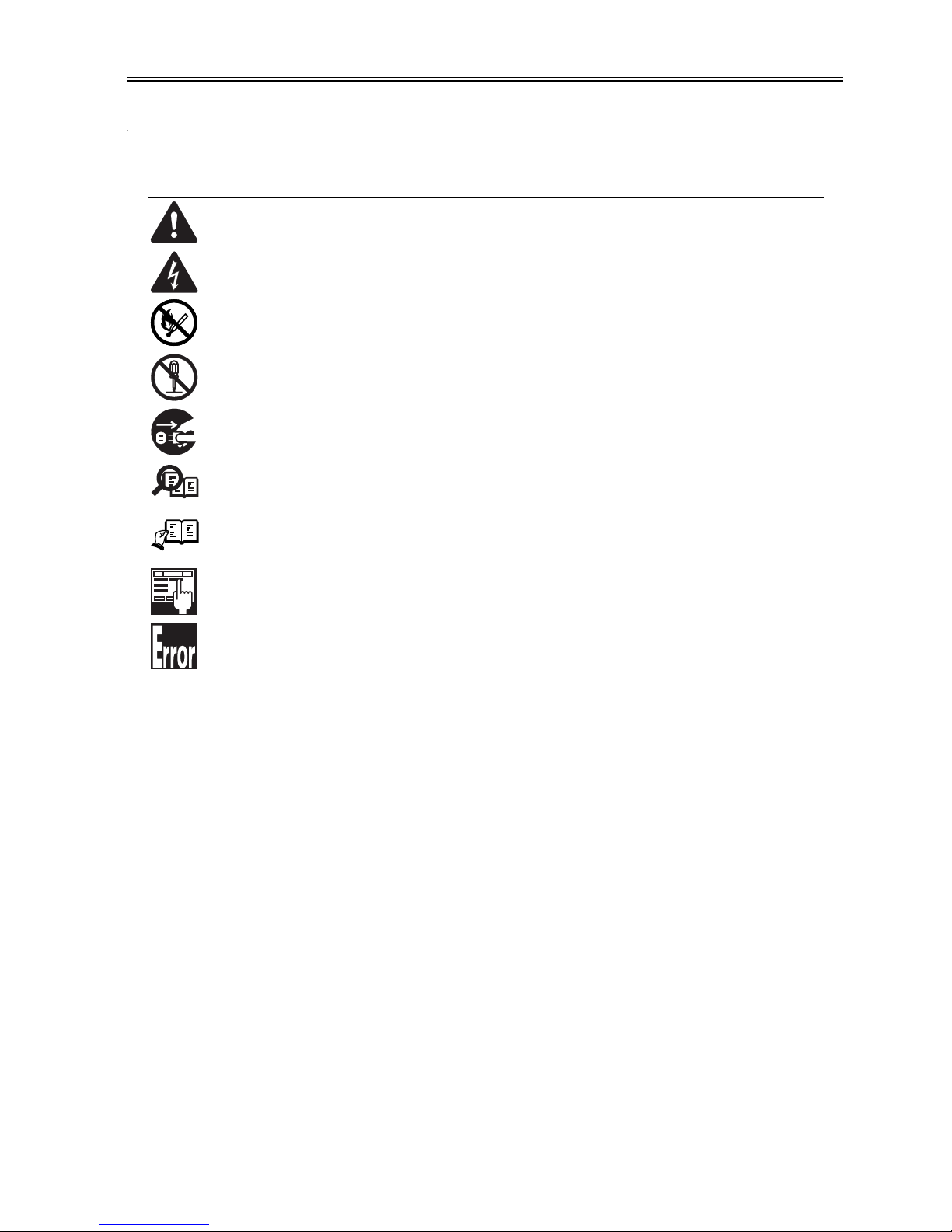
This documentation uses the following symbols to indicate special information:
Symbol Description
Indicates an item of a non-specific nature, possibly classified as Note, Caution, or Warning.
Indicates an item requiring care to avoid electric shocks.
Indicates an item requiring care to avoid combustion (fire).
Indicates an item prohibiting disassembly to avoid electric shocks or problems.
Indicates an item requiring disconnection of the power plug from the electric outlet.
Indicates an item intended to provide notes assisting the understanding of the topic in question.
Indicates an item of reference assisting the understanding of the topic in question.
Provides a description of a service mode.
Provides a description of the nature of an error indication.
Memo
REF.

Introduction
The following rules apply throughout this Service Manual:
1. Each chapter contains sections explaining the purpose of specific functions and the relationship between electrical and mechanical systems with reference to the timing of operation.
In the diagrams, represents the path of mechanical drive; where a signal name accompanies the symbol , the arrow indicates the
direction of the electric signal.
The expression "turn on the power" m eans flipping on the power switch, closing the front door, and closing the delivery unit door, which results in
supplying the machine with power.
2. In the digital circuits, '1'is used to indicate that the voltage level of a given signal is "High", while '0' is used to indicate "Low".(The voltage value, however, differs from circuit to circuit.) In addition, the asterisk (*) as in "DRMD*" indicates that the DRMD signal goes on when '0'.
In practically all cases, the internal mechanisms of a microprocessor cannot be checked in the fi eld. Therefore, the operations of the microprocessors
used in the machines are not discussed: they are explained in terms of from sensors to the input of the DC controller PCB and from the output of the
DC controller PCB to the loads.
The descriptions in this Service Manual are subject to change without notice for product improvement or other purposes, and major changes will be communicated in the form of Service Information bulletins.
All service persons are expected to have a good understanding of the contents of this Service Manual and all relevant Service Information bulletins and be
able to identify and isolate faults in the machine."


Contents
Contents
Chapter 1 PRODUCT DESCRIPTION
1.1 Features .....................................................................................................................................................1- 1
1.1.1 Feature....................................................................................................................................................................1- 1
1.2 Product Specifications................................................................................................................................1- 1
1.2.1 Product Specifications.............................................................................................................................................1- 1
1.3 Detailed Specifications ...............................................................................................................................1- 2
1.3.1 Print Speed.................................................................................................................................................... ... .......1- 2
1.4 Name of Parts.............................................................................................................................................1- 3
1.4.1 External View............................................................................................... .. ..........................................................1- 3
1.4.2 Cross Sectional View..................................................................................................................................... ... .......1- 4
1.5 Using the Machine......................................................................................................................................1- 5
1.5.1 Control Panel ...........................................................................................................................................................1- 5
1.6 Safety .........................................................................................................................................................1- 6
1.6.1 Safety of the Laser Light............................................................................................................................. ... ..........1- 6
1.6.2 CDRH Regulation .................................................................................................................................................. .1- 6
1.6.3 Handling the Laser Unit...........................................................................................................................................1- 6
1.6.4 Points to note at disassembly/installation procedure...............................................................................................1- 7
Chapter 2 TECHNICAL REFERENCE
2.1 Functional Configuration........ ... ... .... ... ... ... .... ... ... ... ... .... ... ... ........................................................................2- 1
2.1.1 Outline.....................................................................................................................................................................2- 1
2.2 Basic Sequense..........................................................................................................................................2- 1
2.2.1 Basic Sequence of Operation.......................................................................................................... ... .....................2- 1
2.3 LASER EXPOSURE SYSTEM...................................................................................................................2- 2
2.3.1 Overview/Configuration...........................................................................................................................................2- 2
2.3.1.1 Outline......................................................................................................................................................................................2- 2
2.3.2 Laser Scanner Motor Control ..................................................................................................................................2- 2
2.3.2.1 Fault Detection......................................................................................................................................................................... 2- 2
2.4 IMAGE FORMATION SYSTEM..................................................................................................................2- 3
2.4.1 Overview/Configuration...........................................................................................................................................2- 3
2.4.1.1 Outline......................................................................................................................................................................................2- 3
2.4.1.2 Image-formation Process......................................................................................................................................................... 2- 3
2.4.1.3 Latent image formation block................................................................................................................................................... 2- 4
2.4.1.4 Development block ........................................... ..................... ..................... ..................... ........................................................ 2- 4
2.4.1.5 Transfer block .......................................................................................................................................................................... 2- 5
2.4.1.6 Fixing block.............................................................................................................................................................................. 2- 6
2.4.1.7 ITB cleaning block....................................................................................................................................................................2- 6
2.4.1.8 Photosensitive drum cleaning block......................................................................................................................................... 2- 7
2.4.2 High-Voltage Control.................................................................................................................... ...........................2- 7
2.4.2.1 Outline......................................................................................................................................................................................2- 7
2.4.3 Image Stabilizaton Control ......................................................................................................................................2- 8
2.4.3.1 Overview of the Image Stabilization Control Mechanism......................................................................................................... 2- 8
2.4.3.2 Image density correction control (D-max control) .................................................................................................................... 2- 8
2.4.3.3 Image gradation correction control (D-half control) ................ ..................... ..................... ........................................................2- 9
2.4.3.4 Color displacement correction control...................................................................................................................................... 2- 9
2.4.4 Toner Cartridge ......................................................... .................................................. ........................................ ....2- 9
2.4.4.1 Developing roller engagement/disengagement control............................................................................................................ 2- 9
2.4.5 Transfer Unit............................................................................................................................ ................................2- 9
2.4.5.1 Pad transfer ............................................................................................................................................................................. 2- 9
2.5 Pickup/Feeding/Delivery System..............................................................................................................2- 10

Contents
2.5.1 Overview/Configuration..........................................................................................................................................2- 10
2.5.1.1 Outline.................................................................................................................................................................................... 2- 10
2.5.2 Detecting Jams......................................................................................................................................................2- 11
2.5.2.1 Jam Detection Outline............................................................................................................................................................ 2- 11
2.5.2.2 Delay Jams ............................................................................................................................................................................ 2- 11
2.5.2.3 Stationary Jams ..................................................................................................................................................................... 2- 11
2.5.2.4 Other Jams ............................................................................................................................................................................ 2- 11
2.5.3 Cassette Pickup.....................................................................................................................................................2- 12
2.5.3.1 Separation Roller Method ...................................................................................................................................................... 2- 12
2.6 FIXING UNIT SYSTEM ............................................................................................................................2- 12
2.6.1 Overview/Configuration..........................................................................................................................................2- 12
2.6.1.1 Outline.................................................................................................................................................................................... 2- 12
2.6.2 Various Control Mechanisms.................................................................................................................................2- 13
2.6.2.1 Controlling the Speed of the Fixing Unit ................................................................................................................................2- 13
2.6.2.2 Fixing Temperature Control ................................................................................................................................................... 2- 13
2.6.3 Protective Functions ..............................................................................................................................................2- 14
2.6.3.1 Protective function .................................................................................................................................................................2- 14
2.6.3.2 Fixing unit failure detection .................................................................................................................................................... 2- 14
2.7 EXTERNAL AND CONTROLS SYSTEM .................................................................................................2- 14
2.7.1 Power Supply............................................................ ... ................................................... .......................................2- 14
2.7.1.1 Power Supply......................................................................................................................................................................... 2- 14
2.7.1.2 Other Function ....................................................................................................................................................................... 2- 15
2.8 ENGINE CONTROL SYSTEM .......................................................... ... ... .... ... ... .......................................2- 15
2.8.1 DC Controller..................... ................................................... .................................................................................2- 15
2.8.1.1 Outline.................................................................................................................................................................................... 2- 15
2.8.1.2 Motor control..........................................................................................................................................................................2- 16
2.8.1.3 Safety..................................................................................................................................................................................... 2- 17
2.8.2 Main Controller.......................................................................................................................................................2- 17
2.8.2.1 Outline.................................................................................................................................................................................... 2- 17
2.8.2.2 Overview of the Block ............................................................................................................................................................ 2- 17
Chapter 3 DISASSEMBLY AND ASSEMBLY
3.1 EXTERNAL AND CONTROLS SYSTEM ...................................................................................................3- 1
3.1.1 Rear Cover........................................................................................................................ ... ....................................3- 1
3.1.1.1 Before Removing the Rear Door.............................................................................................................................................. 3- 1
3.1.1.2 Removing the Rear Door ......................................................................................................................................................... 3- 1
3.1.2 Rear Side Cover ...................................................................................................................................... ................3- 1
3.1.2.1 Before Removing the Rear Side Cover.................................................................................................................................... 3- 1
3.1.2.2 Removing the Rear Side Cover ............................................................................................................................................... 3- 1
3.1.3 Rear Upper Cover............................................................................................................................................... ... ..3- 1
3.1.3.1 Before Removing the Upper Rear Cover.................................................................................................................................3- 1
3.1.3.2 Removing the Upper Rear Cover............................................................................................................................................. 3- 1
3.1.4 Right Cover..................................................................................................................................... .........................3- 2
3.1.4.1 Removing the Right Cover.......................................................................................................................................................3- 2
3.1.5 Left Cover ................................................................................................................................................................3- 2
3.1.5.1 Removing the Left Cover ......................................................................................................................................................... 3- 2
3.1.6 Upper Cover.............................................................................................................................................................3- 3
3.1.6.1 Before Removing the Upper Cover Assembly ......................................................................................................................... 3- 3
3.1.6.2 Removing the Upper Cover Assembly.....................................................................................................................................3- 3
3.1.7 Front Cover..................................................................................................................................... .........................3- 3
3.1.7.1 Removing the Front Door......................................................................................................................................................... 3- 3
3.1.8 Main Drive Unit ........................................................................................................................................................3- 5
3.1.8.1 Before Removing the Main Drive Assembly ............................................................................................................................ 3- 5
3.1.8.2 Removing the Main Drive Assembly........................................................................................................................................ 3- 6
3.1.9 Sub Driver Unit................................. ................................................... .................................... ... ..............................3- 8
3.1.9.1 Before Removing the Sub Drive Assembly..............................................................................................................................3- 8
3.1.9.2 Removing the Sub Drive Assembly .........................................................................................................................................3- 8
3.1.10 Main Motor....................... ... .................................................. ... ....................................... .......................................3- 8

Contents
3.1.10.1 Before Removing the Main Motor .......................................................................................................................................... 3- 8
3.1.10.2 Removing the Main Motor......................................................................................................................................................3- 8
3.1.11 Operation Panel Unit .............................................................................................................................................3- 9
3.1.11.1 Before Removing the Control Panel....................................................................................................................................... 3- 9
3.1.11.2 Removing the Control Panel .................................................................................................................................................. 3- 9
3.1.12 DC Controller PCB.......................................................................................... ... ..................................................3- 10
3.1.12.1 Before Removing the DC Controller PCB ............................................................................................................................ 3- 10
3.1.12.2 Removing the DC Controller PCB........................................................................................................................................ 3- 10
3.1.12.3 After Replacing the DC controller PCB ................................................................................................................................ 3- 10
3.1.13 Main Controller PCB.............................................................. ... ...........................................................................3- 10
3.1.13.1 Before Removing the Main Controller PCB..........................................................................................................................3- 10
3.1.13.2 Removing the Main Controller PCB ..................................................................................................................................... 3- 11
3.1.13.3 After Replacing the Main Controller PCB............................................................................................................................. 3- 11
3.1.14 Low-Voltage Power Supply Assembly.................................................................................................................3- 11
3.1.14.1 Before Removing the Low-Voltage Power Supply Assembly............................................................................................... 3- 11
3.1.14.2 Removing the Low-Voltage Power Supply Assembly .......................................................................................................... 3- 11
3.1.15 Fixing Power Supply Assembly ...........................................................................................................................3- 12
3.1.15.1 Before Removing the Fixing Power Supply Assembly......................................................................................................... 3- 12
3.1.15.2 Removing the Fixing Power Supply Assembly..................... ................................................................................................ 3- 12
3.1.16 High-voltage PCB................................................................................................................................................3- 13
3.1.16.1 Before Removing the High-Voltage Power Supply PCB......................................................................................................3- 13
3.1.16.2 Removing the High-Voltage Power Supply PCB..................................................................................................................3- 13
3.2 LASER EXPOSURE SYSTEM.................................................................................................................3- 13
3.2.1 Laser Scanner Unit................................................................................................................................................3- 13
3.2.1.1 Before Removing the Laser Scanner Unit .............................................................................................................................3- 13
3.2.1.2 Removing the Laser Scanner Unit......................................................................................................................................... 3- 13
3.2.1.3 After Replacing the laser scanner unit...................................................................................................................................3- 15
3.3 IMAGE FORMATION SYSTEM................................................................................................................3- 15
3.3.1 Intermediate Transfer Unit.....................................................................................................................................3- 15
3.3.1.1 Before Removing the ITB Unit ............................................................................................................................................... 3- 15
3.3.1.2 Removing the ITB Unit........................................................................................................................................................... 3- 16
3.4 PICKUP/FEEDING/DELIVERY SYSTEM.................................................................................................3- 17
3.4.1 Cassette Pickup Roller..........................................................................................................................................3- 17
3.4.1.1 Removing the Pickup Roller......... .......................................................................................................................................... 3- 17
3.4.2 Cassette Separation Roller....................................................................................................................................3- 18
3.4.2.1 Removing the Separation Roller............................................................................................................................................3- 18
3.5 FIXING SYSTEM......................................................................................................................................3- 19
3.5.1 Fixing Assembly ............................................................................................................. .......................................3- 19
3.5.1.1 Before Removing the Fixing Assembly..................................................................................................................................3- 19
3.5.1.2 Removing the Fixing Assembly.............................................................................................................................................. 3- 19
3.5.2 Fixing Film Unit......................................................................................................................................................3- 20
3.5.2.1 Before Removing the Fixing Film Unit ...................................................................................................................................3- 20
3.5.2.2 Removing the Fixing Film Unit...............................................................................................................................................3- 20
3.5.3 Fixing Pressure Roller...........................................................................................................................................3- 21
3.5.3.1 Before Removing the Fixing Pressure Roller......................................................................................................................... 3- 21
3.5.3.2 Removing the Fixing Pressure Roller ....................................................................................................................................3- 21
3.5.4 Fixing Motor.................................................................. .........................................................................................3- 21
3.5.4.1 Before Removing the Fixing Motor ........................................................................................................................................ 3- 21
3.5.4.2 Removing the Fixing Motor....................................................................................................................................................3- 21
Chapter 4 MAINTENANCE AND INSPECTION
4.1 Periodically Replaced Parts...... ... .... ... ... .......................................... ... .... ... ... ... ... .... ... ... ... ...........................4- 1
4.1.1 Periodically Replaced Parts.....................................................................................................................................4- 1
4.2 Consumables..............................................................................................................................................4- 1
4.2.1 Life Expectancy of Consumable Parts.....................................................................................................................4- 1
4.3 Periodical Service.......................................................................................................................................4- 1
4.3.1 Periodic Service.......................................................................................................................................................4- 1

Contents
4.4 Cleaning .....................................................................................................................................................4- 1
4.4.1 Cleaning Point......................................................................................................................... ... ..............................4- 1
4.4.2 Pickup Roller........................................................... .. ................................................... ............................................4- 1
4.4.3 Separation Roller........................ .. ... ................................................... .. ........................................ ...........................4- 2
4.4.4 Front Fixing Guide ................................................................................................................................... ................4- 2
4.4.5 Feed Guide........................................................................ ......................................................................................4- 2
Chapter 5 TROUBLESHOOTING
5.1 MEASUREMENT AND ADJUSTMENT............................. ... ... ... .... ... ... ... .... ......................................... .... ..5- 1
5.1.1 Test Print.................................. ... .................................................. ...........................................................................5- 1
5.1.1.1 Test Pages............................................................................................................................................................................... 5- 1
5.1.2 Adjustment of Laser Exposure System...................................................................................................................5- 1
5.1.2.1 After Replacing the laser scanner unit.....................................................................................................................................5- 1
5.1.3 Adjustment of Electrical Components.....................................................................................................................5- 1
5.1.3.1 After Replacing the DC controller PCB....................................................................................................................................5- 1
5.1.3.2 After Replacing the Main Controller PCB................................................................................................................................. 5- 1
5.1.4 Adjustment of Fixing System ..................................................................................................................................5- 2
5.1.4.1 Nip-width specifications ........................................................................................................................................................... 5- 2
5.2 SERVICE TOOLS ......................................................................................................................................5- 3
5.2.1 Standard Tools.........................................................................................................................................................5- 3
5.2.2 Solvents and Oils.................................................... .. ............................................................................................. ..5- 3
5.3 ERROR CODE................................. .... ... ... ... .... ... .......................................... ... ... ......................................5- 3
5.3.1 Error code................................................................................................................................................................5- 3
5.4 Version Up........ ... .... ... ... ... .......................................... ... .... .......................................... ...............................5- 6
5.4.1 Outline......................................................................................................................................................................5- 6
5.4.1.1 Overview of Version Upgrading ............................................................................................................................................... 5- 6
5.5 Service Mode .............................................................................................................................................5- 6
5.5.1 Outline......................................................................................................................................................................5- 6
5.5.1.1 Outline...................................................................................................................................................................................... 5- 6
5.5.2 Service Mode Table.................................................................................................................................... ... .. ........5- 7
5.5.2.1 Service Mode Items ................................................................................................................................................................. 5- 7
5.5.2.2 Service Chart Print 1................................................................................................................................................................ 5- 8
5.5.2.3 Service Chart Print 2................................................................................................................................................................ 5- 9
5.5.2.4 Status Print B.........................................................................................................................................................................5- 12
Chapter 6 APPENDIX
6.1 OUTLINE OF ELECTRICAL COMPONENTS............................................................................................6- 1
6.1.1 Clutch/Solenoid........................................................................................................................................... ... ..........6- 1
6.1.1.1 Solenoid................................................................................................................................................................................... 6- 1
6.1.2 Motor............................................................................................................................................... ... ......................6- 1
6.1.2.1 Motor........................................................................................................................................................................................ 6- 1
6.1.3 Sensor......................................................................................................................................................................6- 2
6.1.3.1 Sensor...................................................................................................................................................................................... 6- 2
6.1.4 PCBs........................................................................................................................................................................6- 3
6.1.4.1 PCBs........................................................................................................................................................................................ 6- 3

Chapter 1 PRODUCT DESCRIPTION


Contents
Contents
1.1 Features..........................................................................................................................................................................1-1
1.1.1 Feature.......................................................................................................................................................................................... 1-1
1.2 Product Specifications....................................................................................................................................................1-1
1.2.1 Product Specifications ................................................................................................................................................................. 1-1
1.3 Detailed Specifications ..................................................................................................................................................1-2
1.3.1 Print Speed................................................................................................................................................................................... 1-2
1.4 Name of Parts.................................................................................................................................................................1-3
1.4.1 External View .............................................................................................................................................................................. 1-3
1.4.2 Cross Sectional View................................................................................................................................................................... 1-4
1.5 Using the Machine.........................................................................................................................................................1-5
1.5.1 Control Panel ............................................................................................................................................................................... 1-5
1.6 Safety .............................................................................................................................................................................1-6
1.6.1 Safety of the Laser Light.............................................................................................................................................................. 1-6
1.6.2 CDRH Regulation ....................................................................................................................................................................... 1-6
1.6.3 Handling the Laser Unit............................................................................................................................................................... 1-6
1.6.4 Points to note at disassembly/installation procedure ................................................................................................................... 1-7


Chapter 1
1-1
1.1 Features
1.1.1 Feature
0018-8898
LBP5050N / LBP5050
1. Small and low-cost printer
The printer uses a flat in-line cartridge method for the first time in the small printer. This lowers the height and reduces the printer size. The printer uses the
transfer pad and the separation roller to reduce the parts expenses.
2. Intermediate transfer method
The intermediate transfer method transfers toner images to the Intermediate Transfer Belt (ITB) and transfers the images in four colors onto the print media at
once. It realizes a stabilized color-print on various media without being affected by the primary transfer operation.
3. Improved usability
The printer improves usability by using the pullout cartridge and the front side accessibility to the media. This small-sized printer is user-friendly on the spa ce
of the desktop.
1.2 Product Specifications
1.2.1 Product Specifications
0018-8897
LBP5050N / LBP5050
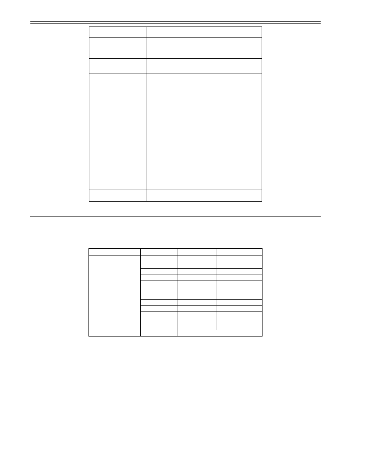
Body installation method Desktop page printer
Photosensitive medium OPC drum
Charging method Roller charging
Exposure method Laser scanning
Development method Contact development
Transfer method Intermediate Transfer Belt (ITB)
Separation method Curvature
Pickup method By cassette/manual feeder
Cassette pickup method Separation pad
Drum cleaning method Rubber blade
Transfer cleaning method Contact charging roller, brush
Fixing method On-demand fixing
Delivery method Face-down
Contrast adjustment function Auto
Toner level detection function Available
Toner type Non-magnetic single-component dry toner
Warm-up time Instant warm-up (25 seconds or less after the printer is turned on)(at 20
deg C)
Image margin (Leading edge) 5.0+1.5/-1.5mm
Image margin (Trailing edge) 5.0+1.5/-1.5mm
Image margin (Left/right) 5.0+1.0/-1.0mm
Number of gradations 16 gradations
Printing resolution 600dpi x 600dpi
First print time B/W: 22 sec or less
Color: 28 sec or less
(When printing A4 paper)
Print speed (A4) Color: approx. 8 pages/min
B/W: approx. 12 pages/min
Cassette paper size Standard sizes: A4, B5, A5, Legal, Letter, Executive, Statement,
Foolscap, 16K, Envelope DL, Envelope COM10, Envelope C5,
Envelope B5, Envelope Monarch and Index Card
Custom paper sizes: 76.2 to 215.9 mm wide and 127.0 to 355.6 mm long
Multifeeder paper size Standard sizes: A4, B5, A5, Legal, Letter, Executive, Statement,
Foolscap, 16K, Envelope DL, Envelope COM10, Envelope C5,
Envelope B5, Envelope Monarch and Index Card
Custom paper sizes: 76.2 to 215.9 mm wide and 127.0 to 355.6 mm long
Cassette paper type Plain paper(75 to 90 g/m2), Thin paper (60 to 74 g/m2), Heavy paper (91
to 163 g/m2), Transparency, Coated paper, Glossy film, Label, Envelope
Monarch , Envelope COM10, Envelope DL, Envelope C5, Envelope B5
Multifeeder tray paper type Plain paper(75 to 90 g/m2), Thin paper (60 to 74 g/m2), Heavy paper (91
to 163 g/m2), Transparency, Coated paper, Glossy film, Label, Envelope
Monarch , Envelope COM10, Envelope DL, Envelope C5, Envelope B5
Cassette capacity Approx. 150 sheets (80 g/m2)
Multifeeder tray capacity 1 sheet
Delivery tray stack Approx. 125 sheets (80 g/m2)
Duplex method None
Memory Standard: 16MB, option: none
Hard disk Standard: none, option: none
Interface LBP5050: USB2.0
LBP5050N: USB2.0,10Base-T/100Base-TX
Operating environment
(Temperature range)
5 to 35 deg C
Chapter 1
1-2
1.3 Detailed Specifications
1.3.1 Print Speed
0019-0064
LBP5050N / LBP5050
T-1-1
Operating environment
(Humidity range)
10 to 80%RH
Operating environment
(Atmospheric pressure)
l810.6 to 1013.3 hpa (0.8 to 1.0 atm)
Noise During standby: Background noise level
During operation: 48 dB (black and white)/47 dB (color)
Power supply rating 110-127 V (±10%), 50/60 Hz (±2 Hz),
220-240 V (±10%), 50/60 Hz (±2 Hz)
Power consumption (Maximum) LBP5050: Approx. 615 W or less (110 - 127 V) / Approx. 665 W or less
(220 - 240 V)
LBP5050N: Approx. 625 W or less (110 - 127 V) / Approx. 980 W or
less (220 - 240 V)
(at 20 deg C)
Power consumption LBP5050
Average during operation (110 - 127 V)
Color printing: Approx. 200 W or less
Black and white printing: Approx. 255 W or less
Average during standby: Approx. 11 W or less
Average during operation (220 - 240 V)
Color printing: Approx. 207 W or less
Black and white printing: Approx. 253 W or less
Average during standby: Approx. 12 W or less
LBP5050N
Average during operation (110 - 127 V)
Color printing: Approx. 210 W or less
Black and white printing: Approx. 255 W or less
Average during standby: Approx. 15 W or less
Average during operation (220 - 240 V)
Color printing: Approx. 210 W or less
Black and white printing: Approx. 258 W or less
Average during standby: Approx. 16 W or less
(at 20 deg C)
Dimensions 399 x 452.5 x 262 mm
Weight Approx. 16.0 kg (excluding toner cartridges)
Paper type Paper size Color B&W
Plain paper
(60 to 90g/m2)
A4 8 12
LTR 8.4 12.6
LGL 6.8 10.2
B5 8.4 7.9
A5 8.4 7.9
EXE 8.4 7.9
Hevey paper
(91 to 163g/m2)
A4 6 6
LTR 6.3 6.3
LGL 5 5
B5 6 6
A5 6 6
EXE 6 6
Post card Post card 5.6
Chapter 1
1-3
1.4 Name of Parts
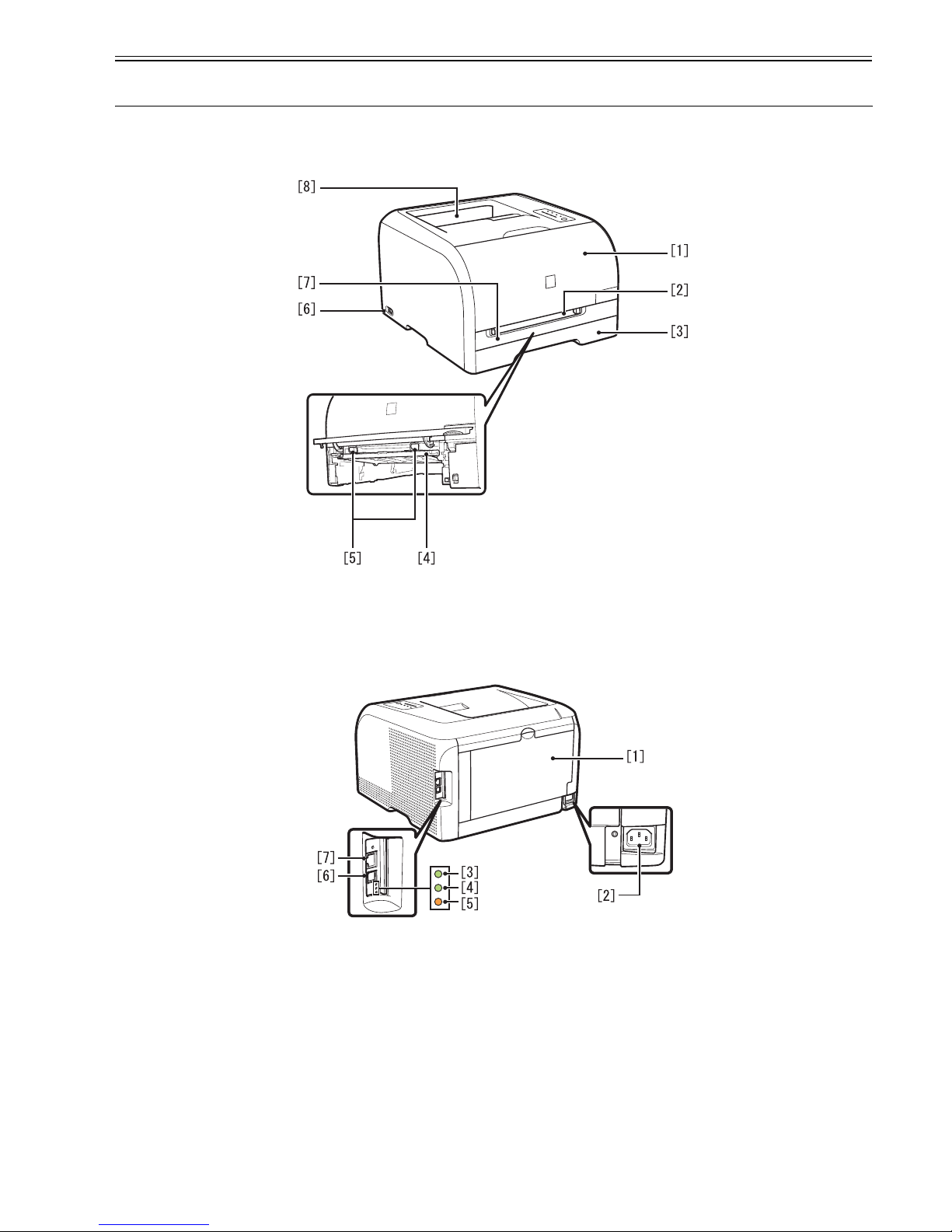
1.4.1 External View
0018-8908
LBP5050N / LBP5050
F-1-1
F-1-2
[1] Front Cover [5] Paper Guides
[2] Manual Feed Slot [6] Power Switch
[3] Paper Cassette [7] Manual Feed Slot Cover
[4] Manual Feed Guide [8] Output Tray
[1] Rear Cover [5] ERR Indicator (Orange)
[2] Power Socket [6] USB Port
[3] 100 Indicator (Green) [7] Ethernet Port
[4] LNK Indicator (Green)
Chapter 1
1-4
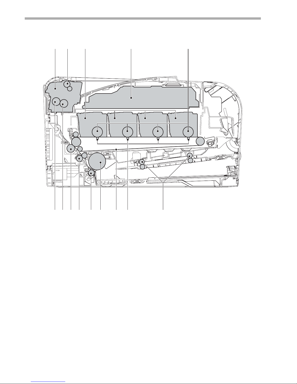
1.4.2 Cross Sectional View
0018-7829
LBP5050N / LBP5050
F-1-3
T-1-2
[1] Fixing unit [8] ITB unit
[2] Delivery roller [9] Pickup roller
[3] Cartridge [10] Separation roller
[4] Laser scanner unit [11] Registration roller
[5] Photosensitive drum [12] Secondary transfer roller
[6] Manual feed roller [13] Fixing film
[7] Primary transfer pad [14] Pressure roller
[1] [2] [3] [4]
[6][7][8][9][10][11][12][13][14]
Chapter 1
1-5
1.5 Using the Machine
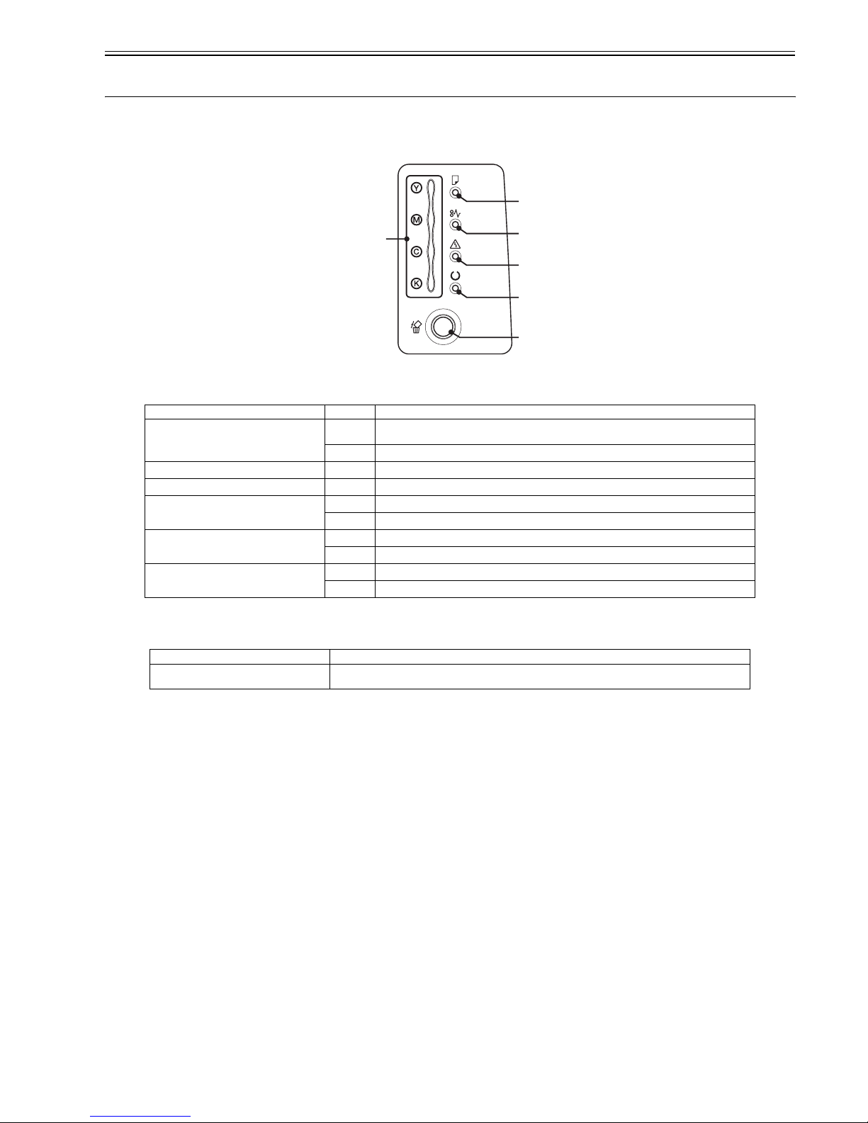
1.5.1 Control Panel
0018-8909
LBP5050N / LBP5050
F-1-4
Functions of the LEDs
T-1-3
Functions of the Control Panel Keys
T-1-4
Name Status Description
[1] Toner Indicator
Blinking
Printing cannot be performed because a toner cartridge needs to be replaced, or a toner cartridge is not
installed properly.
On
A toner cartridge needs to be replaced.
[2] Paper Source Indicator
Blinking
There is no paper or paper of the correct size is not loaded.
[3] Paper Jam Indicator
Blinking
A paper jam has occurred and printing cannot be performed.
[4] Alarm Indicator
Blinking
An error has occurred and printing cannot be performed.
On
A service error has occurred.
[5] Ready Indicator
Blinking
The printer is busy printing, warming up, or cleaning.
On
The printer is ready to print.
[6] Cancel Job Indicator
Blinking
A job is being canceled.
On
The Cancel Job key has been pressed.
Name Function
[6] Cancel Job Key Press this key to cancel the job that is currently being printed or a job with an error.
[2]
[3]
[1]
[4]
[5]
[6]
Chapter 1
1-6
1.6 Safety
1.6.1 Safety of the Laser Light
0019-1638
LBP5050N / LBP5050
Laser beam radiation may pose a danger to the human body. A laser scanner mounted on the machine is sealed with the protection housing and external cover to
prevent the laser beam from leaking to the outside. The laser beam never leaks out of the scanner as far as users operate the machine normally
The following warnings are given to comply with Safety Principles (EN60950).
Laserstrahlen können für den menschlichen Körper gefährlich sein. Aus diesem Grund ist das optische Lasersystem mit einem Schutzgehäuse und einer Au ßenabdeckung dicht verschlossen und hat eine Struktur, die keine Lase rstrahlen nach außen dringen lässt. Unter der Voraussetzun g, dass der Benutzer di eses Gerät normal
bedient, ist ein Austritt von Laserstrahlen daher ausgeschlossen.
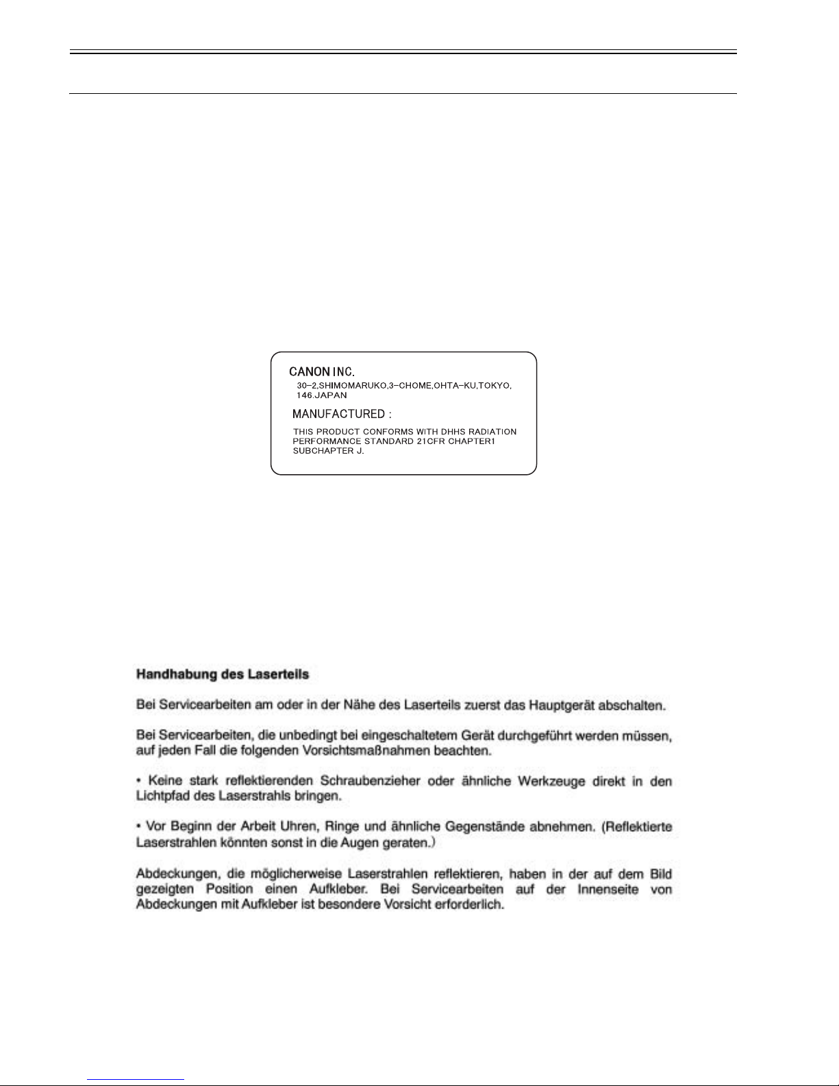
1.6.2 CDRH Regulation
0019-1640
LBP5050N / LBP5050
The Center For Devices and Radiological Health (CDRH) of Food and Drug Administration in U.S. has implemented a regulation regarding laser products on Au-
gust 2nd, 1976. This regulation is applied to all products manufactured since August 1st, 1976, and prohibits the sale of laser products without certification.
The following labels certify compliance with the CDRH regulations, and must be attached to all laser products that are sold in the US.
F-1-5
1.6.3 Handling the Laser Unit
0019-1642
LBP5050N / LBP5050
When servicing the area around the laser assembly, be sure to turn off the main power.
If you must servicr while the power is turned on, be sure to keep the followings:
- Do not use a screwdriver or tools that have a high level of reflectance in the laser path.
- Remove watches and rings before starting the work. (They can reflect the laser beam, possibly hitting the eye.)
The machine's covers that can reflect laser light are identified by means of a warning label (Figure). If you must detach a cover showing the label, be sure to take
extra caution during the work.
The following warnings are given to comply with Safety Principles (EN60950).
F-1-6

Chapter 1
1-7
F-1-7
1.6.4 Points to note at disassembly/installation procedure
0019-1647
LBP5050N / LBP5050
At disassembly/installation procedure, make sure to follow the instruction below to proceed.
1. Be sure to unplug the power code before disassembly/installation.
2. At installation, follow the procedure in the reverse order of disassembly unless otherwise instructed.
3. Be careful of the screw type (length, diameter) and corresponding part.
4. To check the electrical conductivity, washer equipped screw is used to attach the grounding wire and the varistor etc. When attaching them, be sure to use this
screw.
5. In principle, do not operate the machine without any part.
6. Be sure not to unscrew the screw with painting at disassembly.


Chapter 2 TECHNICAL REFERENCE


Contents
Contents
2.1 Functional Configuration...............................................................................................................................................2-1
2.1.1 Outline.......................................................................................................................................................................................... 2-1
2.2 Basic Sequense...............................................................................................................................................................2-1
2.2.1 Basic Sequence of Operation ....................................................................................................................................................... 2-1
2.3 LASER EXPOSURE SYSTEM.....................................................................................................................................2-2
2.3.1 Overview/Configuration .............................................................................................................................................................. 2-2
2.3.1.1 Outline.............................................................................................................................................................................................................2-2
2.3.2 Laser Scanner Motor Control....................................................................................................................................................... 2-2
2.3.2.1 Fault Detection ................................................................................................................................................................................................2-2
2.4 IMAGE FORMATION SYSTEM.................................................................................................................................2-3
2.4.1 Overview/Configuration .............................................................................................................................................................. 2-3
2.4.1.1 Outline.............................................................................................................................................................................................................2-3
2.4.1.2 Image-formation Process ................................................................................................................................................................................2-3
2.4.1.3 Latent image formation block.........................................................................................................................................................................2-4
2.4.1.4 Development block .........................................................................................................................................................................................2-4
2.4.1.5 Transfer block .................................................................................................................................................................................................2-5
2.4.1.6 Fixing block ....................................................................................................................................................................................................2-6
2.4.1.7 ITB cleaning block..........................................................................................................................................................................................2-6
2.4.1.8 Photosensitive drum cleaning block.......................................................... ......................................................................................................2-7
2.4.2 High-Voltage Control .................................................................................................................................................................. 2-7
2.4.2.1 Outline.............................................................................................................................................................................................................2-7
2.4.3 Image Stabilizaton Control .......................................................................................................................................................... 2-8
2.4.3.1 Overview of the Image Stabilization Control Mechanism..............................................................................................................................2-8
2.4.3.2 Image density correction control (D-max control)....................................................................... ...................................................................2-8
2.4.3.3 Image gradation correction control (D-half control).......................................................................................................................................2-9
2.4.3.4 Color displacement correction control............................................................................................................................................................2-9
2.4.4 Toner Cartridge............................................................................................................................................................................ 2-9
2.4.4.1 Developing roller engagement/disengagement control.......................................... .........................................................................................2-9
2.4.5 Transfer Unit................................................................................................................................................................................ 2-9
2.4.5.1 Pad transfer......................................................................................................................................................................................................2-9
2.5 Pickup/Feeding/Delivery System.................................................................................................................................2-10
2.5.1 Overview/Configuration ............................................................................................................................................................ 2-10
2.5.1.1 Outline...........................................................................................................................................................................................................2-10
2.5.2 Detecting Jams........................................................................................................................................................................... 2-11
2.5.2.1 Jam Detection Outline...................................................................................................................................................................................2-11
2.5.2.1.1 Outline .... ......................................... ... ......................................... ... .......................................................................................................2-11
2.5.2.2 Delay Jams ....................................................................................................................................................................................................2-11
2.5.2.2.1 Paper delay JAM ................................................... ... ... ......................................... .................................................................................2-11
2.5.2.2.2 Fixing delay JAM..................................................................................................................................................................................2-11
2.5.2.3 Stationary Jams .............................................................................................................................................................................................2-11
2.5.2.3.1 Pickup residual JAM ................................................ ... ......................................... .................................................................................2-11
2.5.2.3.2 Fixing Stationary Jam ...........................................................................................................................................................................2-11
2.5.2.4 Other Jams.....................................................................................................................................................................................................2-11
2.5.2.4.1 Fixing winding JAM .............................................................................................................................................................................2-11
2.5.2.4.2 In-body residual JAM............................................................................................................................................................................2-11
2.5.2.4.3 Door open JAM.....................................................................................................................................................................................2-11
2.5.3 Cassette Pickup .......................................................................................................................................................................... 2-12
2.5.3.1 Separation Roller Method .............................................................................................................................................................................2-12
2.6 FIXING UNIT SYSTEM.............................................................................................................................................2-12
2.6.1 Overview/Configuration ............................................................................................................................................................ 2-12
2.6.1.1 Outline...........................................................................................................................................................................................................2-12
2.6.2 Various Control Mechanisms .................................................................................................................................................... 2-13
2.6.2.1 Controlling the Speed of the Fixing Unit......................................................................................................................................................2-13

Contents
2.6.2.1.1 Speed control on small size paper (Throughput down control)............................................................................................................ 2-13
2.6.2.2 Fixing Temperature Control .........................................................................................................................................................................2-13
2.6.2.2.1 Fixing temperature control.................................................................................................................................................................... 2-13
2.6.3 Protective Functions................................................................................................................................................................... 2-14
2.6.3.1 Protective function........................................................................................................................................................................................ 2-14
2.6.3.2 Fixing unit failure detection.......................................................................................................................................................................... 2-14
2.7 EXTERNAL AND CONTROLS SYSTEM ............................................................................................................... 2-14
2.7.1 Power Supply............................................................................................................................................................................. 2-14
2.7.1.1 Power Supply................................................................................................................................................................................................ 2-14
2.7.1.1.1 Low-voltage power supply ...................................................................................................................................................................2-14
2.7.1.2 Other Function ..............................................................................................................................................................................................2-15
2.7.1.2.1 Protective function....... .... ......................................... ......................................... ...................................................................................2-15
2.7.1.2.2 Power-save mode.................................................. .... ... ...................................... ... ... .............................................................................2-15
2.8 ENGINE CONTROL SYSTEM ................................................................................................................................. 2-15
2.8.1 DC Controller............................................................................................................................................................................. 2-15
2.8.1.1 Outline .......................................................................................................................................................................................................... 2-15
2.8.1.2 Motor control ................................................................................................................................................................................................2-16
2.8.1.3 Safety ............................................................................................................................................................................................................2-17
2.8.2 Main Controller.......................................................................................................................................................................... 2-17
2.8.2.1 Outline .......................................................................................................................................................................................................... 2-17
2.8.2.2 Overview of the Block..................................................................................................................................................................................2-17
Chapter 2
2-1
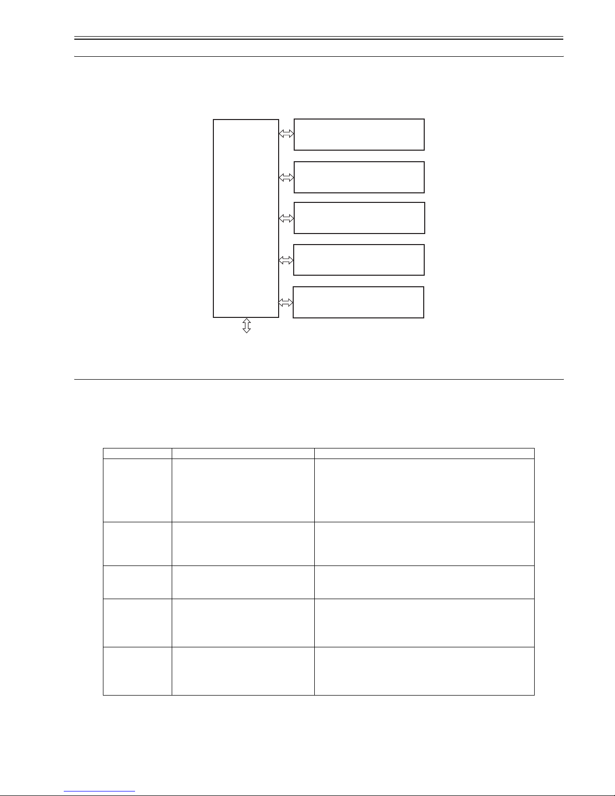
2.1 Functional Configuration
2.1.1 Outline
0019-2379
LBP5050N / LBP5050
The machine may be broadly divided into the following 6 functional blocks: engine control system, laser exposure system, image formation system, pickup/trans-
port/delivery system, fixing system, and externals/auxiliary control system.
F-2-1
2.2 Basic Sequense
2.2.1 Basic Sequence of Operation
0019-2383
LBP5050N / LBP5050
The operational sequence of the printer is controlled by the DC controller in the engine control system.
Table describes periods, durations and operations for each period of a print operation from the printer is turned on until the motors stop rotating.
T-2-1
Period Duration Operation
WAIT From the time the power switch is turned on, the door
is closed or the Sleep mode is released until the
printer gets ready for a print operation
Brings the printer to printable condition
The printer performs the following during this period:
- Detects the pressure roller pressurized status
- Detects the presence of each cartridge and unit
- Determines the homeposition of the development unit
- Cleans the ITB
- Completes any required calibration, such as color
misregistration and image stabilization control
STBY
(Standby)
From the end of WAIT or LSTR period until either
the print command is received from the main
controller or the power switch is turned off
Maintains the printer in printable condition The printer performs the following
during this period:
- Enters Sleep mode when the main controller sends a sleep command
- Completes any required calibration, such as color misregistration control and
image stabilization control, when the main controller sends a command
INTR
(Initial rotation period)
From the time the print command is received from
the main controller during STBY period until the
temperature of the fixing unit reaches the targeted
temperature
Starts up each high-voltage bias, laser scanner unit and fixing unit for preparing a
print operation
PRINT From the end of INTR period until the last media
completes the fixing operation
Forms the image on the photosensitive drum based on the video signals from the
main controller, transfers and fuses the toner image to the print media The printer
performs color misregistration control and image stabilization control at a specified
print interval after the printer is turned on
LSTR
(Last rotation
period)
From the end of PRINT period until the motors stop
rotating
Moves the last printed sheet out of the printer and stops the laser scanner unit
operation and high-voltage biases The printer enters INTR period as soon as the
LSTR period is completed if another print command is received from the main
controller
To external device
Engine control
system
Laser exposure system
Pickup/transport/delivery system
Image formation system
Fixing system
Externals and control system

Chapter 2
2-2
2.3 LASER EXPOSURE SYSTEM
2.3.1 Overview/Configuration
2.3.1.1 Outline
0018-6525
LBP5050N / LBP5050
The laser scanner system forms the latent image on the photosensitive drum according to the VIDEO signals sent from the main controller.
The main components of the laser scanner unit are the laser driver and the scanner motor unit and are controlled by the signals sent from the DC controller.
F-2-2
2.3.2 Laser Scanner Motor Control
2.3.2.1 Fault Detection
0018-6527
LBP5050N / LBP5050
1. Scanner motor failure
- The scanner motor does not reach a specified rotation within a specified period after starting-up the laser scanner motor.
- The rotation of the scanner motor is out of specified range for a specified period during scanner motor drive.
2. BD failure
- The BD interval is detected at out of a specified value during a print operation.
Scaner motor unit
Photosensitive drum
(Y)
BD circuit
Laser driver
LASER CONTROL signal
VIDEO signal
SCANNER MOTOR
SPEED CONTROL signal
BD INPUT signal
Polygon mirror
Photosensitive drum
(M)
Photosensitive drum
(C)
Photosensitive drum
(Bk)
Main controller
DC controller
Chapter 2
2-3
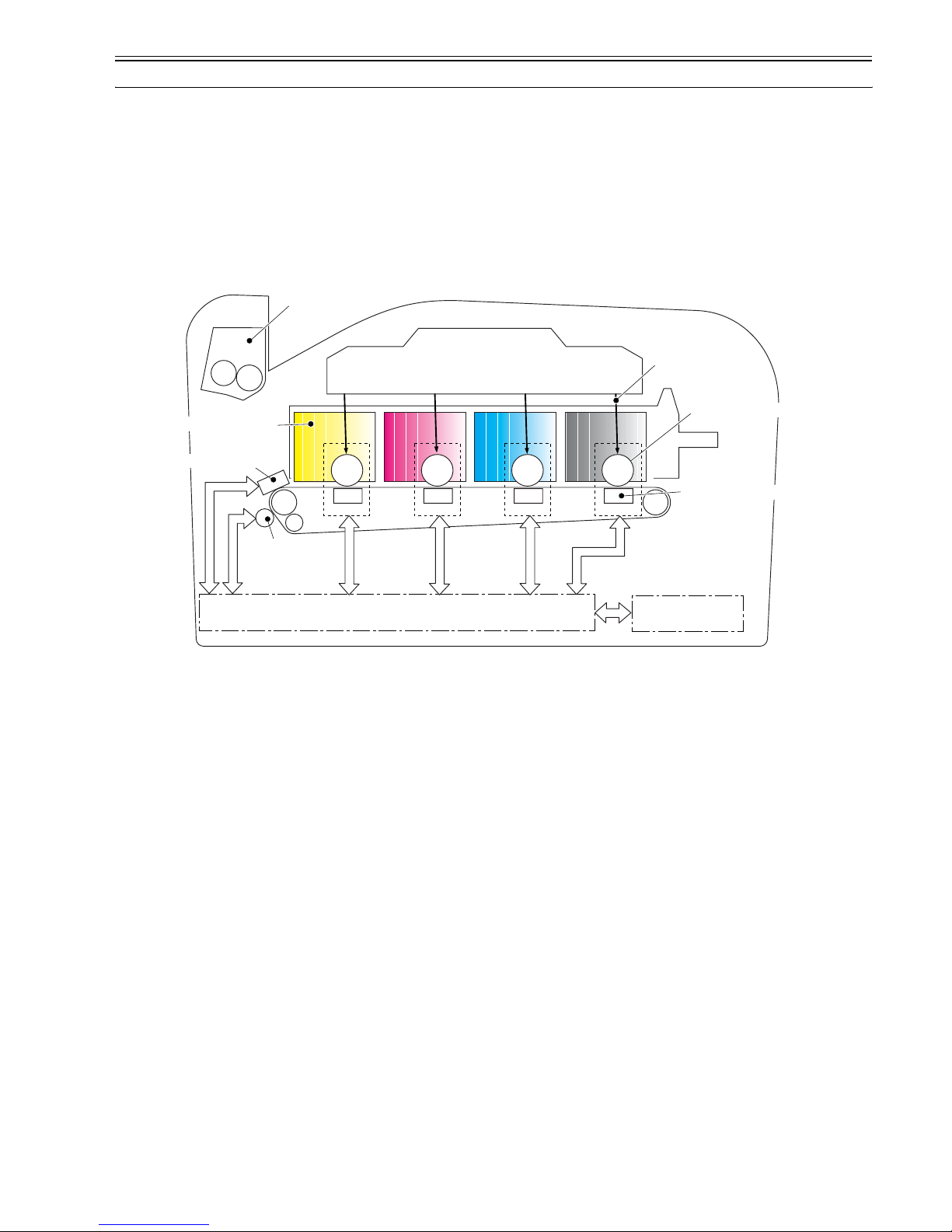
2.4 IMAGE FORMATION SYSTEM
2.4.1 Overview/Configuration
2.4.1.1 Outline
0018-6673
LBP5050N / LBP5050
The image-formation system is the central hub of the printer. It forms the toner image on the media.
The following are the main components of the image-formation system:
- Four toner cartridges
- ITB
- Laser scanner unit
- Fixing unit
The DC controller controls the laser scanner unit and high-voltage power supply to form the toner image on the photosensitive drums according to the VIDEO
signals. The image is transferred to the print media through the ITB and fixed.
F-2-3
2.4.1.2 Image-formation Process
0018-6675
LBP5050N / LBP5050
The image-formation process consists of the following nine steps divided among six functional blocks:
Block 1: Latent image formation
Step 1: Primary charging
Step 2: Laser-beam exposure
Block 2: Development
Step 3: Development
Block 3: Transfer
Step 4: Primary transfer
Step 5: Secondary trans fer
Step 6: Separation
Block 4: Fixing
Step 7: Fixing
Block 5: ITB cleaning
Step 8: ITB cleaning
Block 6: Photosensitive drum cleaning
Step 9: Drum cleaning
DC controllerHigh-voltage power supply
Laser scanner unit
Photosensitive drum
Secondary
transfer rollet
Primary transfer pad
ITB
Tonner cartridge
Laser beam
ITB cleaning unit
Fixing unit

Chapter 2
2-4
F-2-4
2.4.1.3 Latent image formation block
0018-6680
LBP5050N / LBP5050
During the two steps that comprise this block, an invisible latent image is formed on the photosensitive drum.
Step 1: Primary charging
To prepare for latent image formation, the surface of the photosensitive drum is charged with a uniform negative potential.
The primary charging roller charges the photosensitive drum directly. The DC negative bias is applied to the primary charging roller to keep a negative potential
on the drum surface.
F-2-5
Step 2: Laser-beam exposure
The laser beam scans the photosensitive drum to neutralize the negative charge on portions of the drum surface. An electrostatic latent image forms where the
negative charge was neutralized.
F-2-6
2.4.1.4 Development block
0018-6681
LBP5050N / LBP5050
Latent image formation
Transfer
Fixing
Development
Pickup
Registration
5. Secondary transfer
6. Separation
7. Fixing
Delivery
4. Primary transfer
2. Laser-beam exposure
3. Development
8. ITB cleaning
9. Drum cleaning
1. Primary charging
: Media path
: Direction of drum rotation
: Block
: Step
Photosensitive drum cleaningITB cleaning
DC bias
Photosensitive drum
Primary charging roller
Laser beam
Unexposed area Exposed area
 Loading...