

Canon LaserBase MF3240 Service Manual

Service Manual
MF3240 Series
LaserBase MF3240
Mar 31 2006

Application
This manual has been issued by Canon Inc. for qualified persons to learn technical theory, installation, maintenance, and repair
of products. This manual covers all localities where the products are sold. For this reason, there may be information in this
manual that does not apply to your locality.
Corrections
This manual may contain technical inaccuracies or typographical errors due to improvements or changes in products. When
changes occur in applicable products or in the contents of this manual, Canon will release technical information as the need
arises. In the event of major changes in the contents of this manual over a long or short period, Canon will issue a new edition
of this manual.
The following paragraph does not apply to any countries where such provisions are inconsistent with local law.
Trademarks
The product names and company names used in this manual are the registered trademarks of the individual companies.
Copyright
This manual is copyrighted with all rights reserved. Under the copyright laws, this manual may not be copied, reproduced or
translated into another language, in whole or in part, without the written consent of Canon Inc.
COPYRIGHT © 2001 CANON INC.
Printed in Japan
Caution
Use of this manual should be strictly supervised to avoid disclosure of confidential information.
Symbols Used
This documentation uses the following symbols to indicate special information:
Symbol Description
Indicates an item of a non-specific nature, possibly classified as Note, Caution, or Warning.
Indicates an item requiring care to avoid electric shocks.
Indicates an item requiring care to avoid combustion (fire).
Indicates an item prohibiting disassembly to avoid electric shocks or problems.
Indicates an item requiring disconnection of the power plug from the electric outlet.
Indicates an item intended to provide notes assisting the understanding of the topic in question.
Memo
Introduction
REF.
Indicates an item of reference assisting the understanding of the topic in question.
Provides a description of a service mode.
Provides a description of the nature of an error indication.

Introduction
The following rules apply throughout this Service Manual:
1. Each chapter contains sections explaining the purpose of specific functions and the relationship between electrical and mechanical systems with reference to the timing of operation.
In the diagrams, represents the path of mechanical drive; where a signal name accompanies the symbol , the arrow indicates the
direction of the electric signal.
The expression "turn on the power" means flipping on the power switch, closing the front door, and closing the delivery unit door, which results in
supplying the machine with power.
2. In the digital circuits, '1'is used to indicate that the voltage level of a given signal is "High", while '0' is used to indicate "Low".(The voltage value, however, differs from circuit to circuit.) In addition, the asterisk (*) as in "DRMD*" indicates that the DRMD signal goes on when '0'.
In practically all cases, the internal mechanisms of a microprocessor cannot be checked in the field. Therefore, the operations of the microprocessors
used in the machines are not discussed: they are explained in terms of from sensors to the input of the DC controller PCB and from the output of the
DC controller PCB to the loads.
The descriptions in this Service Manual are subject to change without notice for product improvement or other purposes, and major changes will be communicated in the form of Service Information bulletins.
All service persons are expected to have a good understanding of the contents of this Service Manual and all relevant Service Information bulletins and be
able to identify and isolate faults in the machine."

Contents
Contents
Chapter 1 PRODUCT DESCRIPTION
1.1 Detailed Specifications ............................................................................................................................... 1- 1
1.1.1 Printing Speed ........................................................................................................................................................1- 1
1.1.2 Stack Upon Delivery ................................................................................................................................................ 1- 1
1.1.3 System Requirements for Printer Driver ..................................................................................................................1- 1
1.2 Names of Parts ...........................................................................................................................................1- 1
1.2.1 External View...........................................................................................................................................................1- 1
1.2.2 Operation panel .......................................................................................................................................................1- 2
1.3 Safety ......................................................................................................................................................... 1- 3
1.3.1 Safety of Laser Light................................................................................................................................................1- 3
1.3.2 Regulations Under the Center for Devices and Radiological Health (CDRH) .........................................................1- 3
1.3.3 Handling the Laser Unit ...........................................................................................................................................1- 3
1.3.4 Safety of Toner........................................................................................................................................................1- 3
1.3.5 Backup Battery ........................................................................................................................................................1- 4
Chapter 2 TECHNICAL REFERENCE
2.1 Document Feed and Exposure System ......................................................................................................2- 1
2.1.1 Overview/Configuration ...........................................................................................................................................2- 1
2.1.1.1 Overview .................................................................................................................................................................................. 2- 1
2.2 Laser Exposure ..........................................................................................................................................2- 2
2.2.1 Overview/Configuration ...........................................................................................................................................2- 2
2.2.1.1 Overview .................................................................................................................................................................................. 2- 2
2.3 Image Formation ........................................................................................................................................ 2- 3
2.3.1 Overview/Configuration ...........................................................................................................................................2- 3
2.3.1.1 Overview .................................................................................................................................................................................. 2- 3
2.4 Pickup and Feed System............................................................................................................................ 2- 4
2.4.1 Overview/Configuration ...........................................................................................................................................2- 4
2.4.1.1 Overview .................................................................................................................................................................................. 2- 4
2.4.2 Other Control ...........................................................................................................................................................2- 4
2.4.2.1 Manual Pickup Control ............................................................................................................................................................. 2- 4
2.4.2.2 Cassette Pickup Control .......................................................................................................................................................... 2- 4
2.4.3 Detection Jams........................................................................................................................................................2- 5
2.4.3.1 Jam Detection Outline.............................................................................................................................................................. 2- 5
2.4.3.2 Delay Jams .............................................................................................................................................................................. 2- 5
2.4.3.3 Stationary Jams ....................................................................................................................................................................... 2- 5
2.4.3.4 Other Jams .............................................................................................................................................................................. 2- 5
2.5 Fixing Unit................................................................................................................................................... 2- 6
2.5.1 Overview/Configuration ...........................................................................................................................................2- 6
2.5.1.1 Overview .................................................................................................................................................................................. 2- 6
2.5.2 Protection Function..................................................................................................................................................2- 6
2.5.2.1 Protective Mechanisms ............................................................................................................................................................ 2- 6
2.5.2.2 Detecting a Fault in the Fixing Assembly ................................................................................................................................. 2- 6
2.6 External and Controls ................................................................................................................................. 2- 7
2.6.1 Power Supply ..........................................................................................................................................................2- 7
2.6.1.1 Backup Battery......................................................................................................................................................................... 2- 7
Chapter 3 DISASSEMBLY AND ASSEMBLY
3.1 EXTERNAL AND CONTROLS SYSTEM ...................................................................................................3- 1
3.1.1 Front Cover..............................................................................................................................................................3- 1
3.1.1.1 Removing the front cover ......................................................................................................................................................... 3- 1

Contents
3.1.2 Rear Cover...............................................................................................................................................................3- 1
3.1.2.1 Removing the Cassette............................................................................................................................................................ 3- 1
3.1.2.2 Removing the front cover ......................................................................................................................................................... 3- 1
3.1.2.3 Removing the right cover ......................................................................................................................................................... 3- 1
3.1.2.4 Removing the left cover ........................................................................................................................................................... 3- 1
3.1.2.5 Removing the rear cover.......................................................................................................................................................... 3- 1
3.1.3 Top Cover ................................................................................................................................................................3- 2
3.1.3.1 Removing the Cassette............................................................................................................................................................ 3- 2
3.1.3.2 Removing the front cover ......................................................................................................................................................... 3- 2
3.1.3.3 Removing the right cover ......................................................................................................................................................... 3- 2
3.1.3.4 Removing the left cover ........................................................................................................................................................... 3- 2
3.1.3.5 Removing the rear cover.......................................................................................................................................................... 3- 2
3.1.3.6 Removing the Scanner Unit ..................................................................................................................................................... 3- 2
3.1.3.7 Removing the top cover ........................................................................................................................................................... 3- 3
3.1.4 Right Cover..............................................................................................................................................................3- 3
3.1.4.1 Removing the Cassette............................................................................................................................................................ 3- 3
3.1.4.2 Removing the front cover ......................................................................................................................................................... 3- 3
3.1.4.3 Removing the right cover ......................................................................................................................................................... 3- 3
3.1.5 Left Cover ................................................................................................................................................................3- 3
3.1.5.1 Removing the Cassette............................................................................................................................................................ 3- 3
3.1.5.2 Removing the left cover ........................................................................................................................................................... 3- 3
3.1.6 Operation Panel Unit................................................................................................................................................3- 4
3.1.6.1 Removung the Cassette .......................................................................................................................................................... 3- 4
3.1.6.2 Removing the front cover ......................................................................................................................................................... 3- 4
3.1.6.3 Removing the right cover ......................................................................................................................................................... 3- 4
3.1.6.4 Removing the left cover ........................................................................................................................................................... 3- 4
3.1.6.5 Removing the rear cover.......................................................................................................................................................... 3- 4
3.1.6.6 Removing the Scanner Unit ..................................................................................................................................................... 3- 5
3.1.6.7 Removing the Board Unit ......................................................................................................................................................... 3- 5
3.1.6.8 Removing the Operation Panel Unit ........................................................................................................................................ 3- 5
3.1.7 SCNT Board.............................................................................................................................................................3- 6
3.1.7.1 Removing the Cassette............................................................................................................................................................ 3- 6
3.1.7.2 Removing the front cover ......................................................................................................................................................... 3- 6
3.1.7.3 Removing the right cover ......................................................................................................................................................... 3- 6
3.1.7.4 Removing the left cover ........................................................................................................................................................... 3- 6
3.1.7.5 Removing the rear cover.......................................................................................................................................................... 3- 6
3.1.7.6 Removing the Scanner Unit ..................................................................................................................................................... 3- 6
3.1.7.7 Removing the SCNT Board ..................................................................................................................................................... 3- 7
3.1.8 ECNT Board.............................................................................................................................................................3- 7
3.1.8.1 Removing the Cassette............................................................................................................................................................ 3- 7
3.1.8.2 Removing the front cover ......................................................................................................................................................... 3- 7
3.1.8.3 Removing the left cover ........................................................................................................................................................... 3- 7
3.1.8.4 Removing the ECNT Board ..................................................................................................................................................... 3- 7
3.1.9 Power Supply PCB ..................................................................................................................................................3- 8
3.1.9.1 Removing the Cassette............................................................................................................................................................ 3- 8
3.1.9.2 Removing the front cover ......................................................................................................................................................... 3- 8
3.1.9.3 Removing the right cover ......................................................................................................................................................... 3- 8
3.1.9.4 Removing the left cover ........................................................................................................................................................... 3- 8
3.1.9.5 Removing the rear cover.......................................................................................................................................................... 3- 8
3.1.9.6 Removing the Power Supply Shield Plate ............................................................................................................................... 3- 8
3.1.9.7 Removing the Power Supply Assembly ................................................................................................................................... 3- 9
3.1.9.8 Removing the Power Supply Board ......................................................................................................................................... 3- 9
3.1.10 High-voitage Power Supply PCB ...........................................................................................................................3- 9
3.1.10.1 Removing the Cassette.......................................................................................................................................................... 3- 9
3.1.10.2 Removing the front cover ....................................................................................................................................................... 3- 9
3.1.10.3 Removing the right cover ....................................................................................................................................................... 3- 9
3.1.10.4 Removing the left cover ....................................................................................................................................................... 3- 10
3.1.10.5 Removing the rear cover...................................................................................................................................................... 3- 10
3.1.10.6 Removing the Power Supply Shield Plate............................................................................................................................ 3- 10
3.1.10.7 Removing the Power Supply Board ..................................................................................................................................... 3- 10
3.1.10.8 Removing the High-Voltage Power Supply Board ............................................................................................................... 3- 11

Contents
3.1.11 Top Sensor ..........................................................................................................................................................3- 11
3.1.11.1 Removing the Cassette ........................................................................................................................................................ 3- 11
3.1.11.2 Removing the front cover ..................................................................................................................................................... 3- 11
3.1.11.3 Removing the right cover ..................................................................................................................................................... 3- 11
3.1.11.4 Removing the left cover ....................................................................................................................................................... 3- 11
3.1.11.5 Removing the rear cover ...................................................................................................................................................... 3- 12
3.1.11.6 Removing the Scanner Unit ................................................................................................................................................. 3- 12
3.1.11.7 Removing the top cover ....................................................................................................................................................... 3- 12
3.1.11.8 Removing the Right Frame .................................................................................................................................................. 3- 12
3.1.11.9 Removing the Plate.............................................................................................................................................................. 3- 12
3.1.11.10 Removing the Left Frame ................................................................................................................................................... 3- 13
3.1.11.11 Removing the Power Supply Shield Plate .......................................................................................................................... 3- 13
3.1.11.12 Removing the Power Supply Assembly ............................................................................................................................. 3- 13
3.1.11.13 Removing the top sensor ................................................................................................................................................... 3- 13
3.1.12 Paper Delivery Sensor.........................................................................................................................................3- 14
3.1.12.1 Removing the Cassette ........................................................................................................................................................ 3- 14
3.1.12.2 Removing the front cover ..................................................................................................................................................... 3- 14
3.1.12.3 Removing the right cover ..................................................................................................................................................... 3- 14
3.1.12.4 Removing the left cover ....................................................................................................................................................... 3- 14
3.1.12.5 Removing the rear cover ...................................................................................................................................................... 3- 14
3.1.12.6 Removing the Power Supply Shield Plate............................................................................................................................ 3- 14
3.1.12.7 Removing the Scanner Unit ................................................................................................................................................. 3- 15
3.1.12.8 Removing the Plate.............................................................................................................................................................. 3- 15
3.1.12.9 Removing the Paper Delivery Sensor .................................................................................................................................. 3- 15
3.2 Document Feed/Exposure System ...........................................................................................................3- 15
3.2.1 Scanner Unit..........................................................................................................................................................3- 15
3.2.1.1 Removing the Cassette.......................................................................................................................................................... 3- 15
3.2.1.2 Removing the front cover ....................................................................................................................................................... 3- 15
3.2.1.3 Removing the right cover ....................................................................................................................................................... 3- 16
3.2.1.4 Removong the left cover ........................................................................................................................................................ 3- 16
3.2.1.5 Removing the rear cover........................................................................................................................................................ 3- 16
3.2.1.6 Removing the Scanner Unit ................................................................................................................................................... 3- 16
3.2.2 Scanner Cover Unit ............................................................................................................................................... 3- 17
3.2.2.1 Removing the Cassette.......................................................................................................................................................... 3- 17
3.2.2.2 Removing the front cover ....................................................................................................................................................... 3- 17
3.2.2.3 Removing the right cover ....................................................................................................................................................... 3- 17
3.2.2.4 Removing the left cover ......................................................................................................................................................... 3- 17
3.2.2.5 Removing the rear cover........................................................................................................................................................ 3- 17
3.2.2.6 Removing the Scanner Unit ................................................................................................................................................... 3- 17
3.2.2.7 Removing the Operation Panel Unit ...................................................................................................................................... 3- 18
3.2.2.8 Scanner cover unit ................................................................................................................................................................. 3- 18
3.2.3 Contact Sensor......................................................................................................................................................3- 18
3.2.3.1 Removing the Cassette.......................................................................................................................................................... 3- 18
3.2.3.2 Removing the front cover ....................................................................................................................................................... 3- 18
3.2.3.3 Removing the right cover ....................................................................................................................................................... 3- 18
3.2.3.4 Removing the left cover ......................................................................................................................................................... 3- 19
3.2.3.5 Removing the rear cover........................................................................................................................................................ 3- 19
3.2.3.6 Removing the Scanner Unit ................................................................................................................................................... 3- 19
3.2.3.7 Removing the Operation Panel Unit ...................................................................................................................................... 3- 19
3.2.3.8 Removing the Scanner Cover Unit ........................................................................................................................................ 3- 20
3.2.3.9 Removing the Flatbed Motor Unit .......................................................................................................................................... 3- 20
3.2.3.10 Removing the Contact Sensor ............................................................................................................................................. 3- 20
3.2.4 Flatbed Motor Unit .................................................................................................................................................3- 20
3.2.4.1 Removing the Cassette.......................................................................................................................................................... 3- 20
3.2.4.2 Removing the front cover ....................................................................................................................................................... 3- 20
3.2.4.3 Removing the right cover ....................................................................................................................................................... 3- 21
3.2.4.4 Removing the left cover ......................................................................................................................................................... 3- 21
3.2.4.5 Removing the rear cover........................................................................................................................................................ 3- 21
3.2.4.6 Removing the Scanner Unit ................................................................................................................................................... 3- 21
3.2.4.7 Removing the Operation Panel Unit ...................................................................................................................................... 3- 22
3.2.4.8 Removing the Scanner Cover Unit ........................................................................................................................................ 3- 22

Contents
3.2.4.9 Removing the Flatbed Motor Unit .......................................................................................................................................... 3- 22
3.3 LASER EXPOSURE SYSTEM ................................................................................................................. 3- 22
3.3.1 Laser/Scanner Unit ................................................................................................................................................3- 22
3.3.1.1 Removing the Cassette.......................................................................................................................................................... 3- 22
3.3.1.2 Removing the front cover ....................................................................................................................................................... 3- 22
3.3.1.3 Removing the right cover ....................................................................................................................................................... 3- 23
3.3.1.4 Removing the left cover ......................................................................................................................................................... 3- 23
3.3.1.5 Removing the rear cover........................................................................................................................................................ 3- 23
3.3.1.6 Removing the Scanner Unit ................................................................................................................................................... 3- 23
3.3.1.7 Removing the top cover ......................................................................................................................................................... 3- 24
3.3.1.8 Removing the Laser/Scanner Unit ......................................................................................................................................... 3- 24
3.4 IMAGE FORMATION SYSTEM................................................................................................................ 3- 24
3.4.1 Transfer Charging Roller........................................................................................................................................3- 24
3.4.1.1 Removing the Transfer Charging Roller ................................................................................................................................ 3- 24
3.5 PICKUP AND FEEDING SYSTEM........................................................................................................... 3- 24
3.5.1 Cassette Pickup Roller...........................................................................................................................................3- 24
3.5.1.1 Removing the Cassette.......................................................................................................................................................... 3- 24
3.5.1.2 Removing the front cover ....................................................................................................................................................... 3- 24
3.5.1.3 Removing the right cover ....................................................................................................................................................... 3- 25
3.5.1.4 Removing the left cover ......................................................................................................................................................... 3- 25
3.5.1.5 Removing the rear cover........................................................................................................................................................ 3- 25
3.5.1.6 Removing the Scanner Unit ................................................................................................................................................... 3- 25
3.5.1.7 Removing the top cover ......................................................................................................................................................... 3- 25
3.5.1.8 Removing the Right Frame .................................................................................................................................................... 3- 26
3.5.1.9 Removing the Plate................................................................................................................................................................ 3- 26
3.5.1.10 Removing the Left Frame..................................................................................................................................................... 3- 26
3.5.1.11 Removing the Power Supply Shield Plate............................................................................................................................ 3- 26
3.5.1.12 Removing the Power Supply Assembly ............................................................................................................................... 3- 26
3.5.1.13 Removing the Gear Unit....................................................................................................................................................... 3- 27
3.5.1.14 Removing the Tooth-Missing Gear ...................................................................................................................................... 3- 27
3.5.2 Cassette Pickup Solenoid......................................................................................................................................3- 27
3.5.2.1 Removing the Cassette.......................................................................................................................................................... 3- 27
3.5.2.2 Removing the front cover ....................................................................................................................................................... 3- 27
3.5.2.3 Removing the right cover ....................................................................................................................................................... 3- 27
3.5.2.4 Removing the left cover ......................................................................................................................................................... 3- 28
3.5.2.5 Removing the rear cover........................................................................................................................................................ 3- 28
3.5.2.6 Removing the Scanner Unit ................................................................................................................................................... 3- 28
3.5.2.7 Removing the top cover ......................................................................................................................................................... 3- 28
3.5.2.8 Removing the Right Frame .................................................................................................................................................... 3- 29
3.5.2.9 Removing the Plate................................................................................................................................................................ 3- 29
3.5.2.10 Removing the Left Frame..................................................................................................................................................... 3- 29
3.5.2.11 Removing the Power Supply Shield Plate............................................................................................................................ 3- 29
3.5.2.12 Removing the Power Supply Assembly ............................................................................................................................... 3- 29
3.5.2.13 Removing the Cassette Pickup Solenoid ............................................................................................................................. 3- 30
3.5.3 Cassette Separation Pad.......................................................................................................................................3- 30
3.5.3.1 Removing the Cassette.......................................................................................................................................................... 3- 30
3.5.3.2 Removing the Rear of the Cassette ....................................................................................................................................... 3- 30
3.5.3.3 Removing the Cassette Separation Pad ................................................................................................................................ 3- 30
3.5.4 Paper Feed Roller..................................................................................................................................................3- 30
3.5.4.1 Removing the Cassette.......................................................................................................................................................... 3- 30
3.5.4.2 Removing the front cover ....................................................................................................................................................... 3- 30
3.5.4.3 Removing the right cover ....................................................................................................................................................... 3- 30
3.5.4.4 Removing the left cover ......................................................................................................................................................... 3- 31
3.5.4.5 Removing the rear cover........................................................................................................................................................ 3- 31
3.5.4.6 Removing the Scanner Unit ................................................................................................................................................... 3- 31
3.5.4.7 Removing the top cover ......................................................................................................................................................... 3- 31
3.5.4.8 Removing the Right Frame .................................................................................................................................................... 3- 31
3.5.4.9 Removing the Plate................................................................................................................................................................ 3- 32
3.5.4.10 Removing the Left Frame..................................................................................................................................................... 3- 32
3.5.4.11 Removing the Power Supply Shield Plate............................................................................................................................ 3- 32

Contents
3.5.4.12 Removing the Power Supply Assembly ............................................................................................................................... 3- 32
3.5.4.13 Removing the Gear Unit....................................................................................................................................................... 3- 33
3.5.4.14 Removing the Tooth-Missing Gear ...................................................................................................................................... 3- 33
3.5.4.15 Removing the Paper Feed Guide......................................................................................................................................... 3- 33
3.5.4.16 Removing the Paper Feed Roller ......................................................................................................................................... 3- 33
3.5.5 Manual Pickup Solenoid ........................................................................................................................................3- 33
3.5.5.1 Removing the Cassette.......................................................................................................................................................... 3- 33
3.5.5.2 Removing the front cover ....................................................................................................................................................... 3- 33
3.5.5.3 Removing the right cover ....................................................................................................................................................... 3- 34
3.5.5.4 Removing the left cover ......................................................................................................................................................... 3- 34
3.5.5.5 Removing the Scanner Unit ................................................................................................................................................... 3- 34
3.5.5.6 Removing the top cover ......................................................................................................................................................... 3- 34
3.5.5.7 Removing the Right Frame .................................................................................................................................................... 3- 35
3.5.5.8 Removing the Plate................................................................................................................................................................ 3- 35
3.5.5.9 Removing the Left Frame ...................................................................................................................................................... 3- 35
3.5.5.10 Removing the Power Supply Shield Plate............................................................................................................................ 3- 35
3.5.5.11 Removing the Power Supply Assembly ............................................................................................................................... 3- 35
3.5.5.12 Removing the Manual Pickup Solenoid ............................................................................................................................... 3- 36
3.5.6 Main Motor.............................................................................................................................................................3- 36
3.5.6.1 Removing the Cassette.......................................................................................................................................................... 3- 36
3.5.6.2 Removing the front cover ....................................................................................................................................................... 3- 36
3.5.6.3 Removing the right cover ....................................................................................................................................................... 3- 36
3.5.6.4 Removing the left cover ......................................................................................................................................................... 3- 36
3.5.6.5 Removing the rear cover........................................................................................................................................................ 3- 37
3.5.6.6 Removing the Scanner Unit ................................................................................................................................................... 3- 37
3.5.6.7 Removing the top cover ......................................................................................................................................................... 3- 37
3.5.6.8 Removing the Right Frame .................................................................................................................................................... 3- 37
3.5.6.9 Removing the Plate................................................................................................................................................................ 3- 37
3.5.6.10 Removing the Left Frame..................................................................................................................................................... 3- 38
3.5.6.11 Removing the Power Supply Shield Plate............................................................................................................................ 3- 38
3.5.6.12 Removing the Main Motor .................................................................................................................................................... 3- 38
3.5.7 Gear Unit ............................................................................................................................................................... 3- 38
3.5.7.1 Removing the Cassette.......................................................................................................................................................... 3- 38
3.5.7.2 Removing the front cover ....................................................................................................................................................... 3- 38
3.5.7.3 Removing the right cover ....................................................................................................................................................... 3- 38
3.5.7.4 Removing the Gear Unit ........................................................................................................................................................ 3- 39
3.6 FIXING SYSTEM ......................................................................................................................................3- 39
3.6.1 Fixing Film Unit......................................................................................................................................................3- 39
3.6.1.1 Removing the Cassette.......................................................................................................................................................... 3- 39
3.6.1.2 Removing the front cover ....................................................................................................................................................... 3- 39
3.6.1.3 Removing the right cover ....................................................................................................................................................... 3- 39
3.6.1.4 Removing the left cover ......................................................................................................................................................... 3- 39
3.6.1.5 Removing the rear cover........................................................................................................................................................ 3- 40
3.6.1.6 Removing the Scanner Unit ................................................................................................................................................... 3- 40
3.6.1.7 Removing the top cover ......................................................................................................................................................... 3- 40
3.6.1.8 Removing the Right Frame .................................................................................................................................................... 3- 40
3.6.1.9 Removing the Plate................................................................................................................................................................ 3- 40
3.6.1.10 Removing the Left Frame..................................................................................................................................................... 3- 41
3.6.1.11 Removing the Power Supply Shield Plate............................................................................................................................ 3- 41
3.6.1.12 Removing the Fixing Film Unit ............................................................................................................................................. 3- 41
3.6.2 Fixing Pressure Roller ...........................................................................................................................................3- 42
3.6.2.1 Removing the Cassette.......................................................................................................................................................... 3- 42
3.6.2.2 Removing the front cover ....................................................................................................................................................... 3- 42
3.6.2.3 Removing the right cover ....................................................................................................................................................... 3- 42
3.6.2.4 Removing the left cover ......................................................................................................................................................... 3- 42
3.6.2.5 Removing the rear cover........................................................................................................................................................ 3- 42
3.6.2.6 Removing the Scanner Unit ................................................................................................................................................... 3- 42
3.6.2.7 Removing the top cover ......................................................................................................................................................... 3- 43
3.6.2.8 Removing the Right Frame .................................................................................................................................................... 3- 43
3.6.2.9 Removing the Plate................................................................................................................................................................ 3- 43
3.6.2.10 Removing the Left Frame..................................................................................................................................................... 3- 43

Contents
3.6.2.11 Removing the Power Supply Shield Plate............................................................................................................................ 3- 43
3.6.2.12 Removing the Fixing Film Unit ............................................................................................................................................. 3- 44
3.6.2.13 Removing the Fixing Pressure Roller................................................................................................................................... 3- 44
Chapter 4 MAINTENANCE AND INSPECTION
4.1 Periodically Replaced Parts ....................................................................................................................... 4- 1
4.1.1 Periodic Replacement Parts ....................................................................................................................................4- 1
4.2 Periodical Service....................................................................................................................................... 4- 1
4.2.1 Periodical Service ....................................................................................................................................................4- 1
4.3 Cleaning ..................................................................................................................................................... 4- 1
4.3.1 Items Requiring Cleaning.........................................................................................................................................4- 1
4.3.2 Cleaning Method (external covers)..........................................................................................................................4- 1
4.3.3 Cleaning Method (scanning unit) .............................................................................................................................4- 2
4.3.4 Cleaning Method (printer unit) .................................................................................................................................4- 2
4.4 Lubrications ................................................................................................................................................ 4- 3
4.4.1 Areas Requiring Application of Grease....................................................................................................................4- 3
4.4.2 Delivery Idler Gear...................................................................................................................................................4- 3
4.4.3 Wheel Shaft .............................................................................................................................................................4- 4
4.4.4 Fixing Drive Transmission Gear...............................................................................................................................4- 4
4.4.5 Large Gear...............................................................................................................................................................4- 4
4.4.6 Feed Gear................................................................................................................................................................4- 5
4.4.7 Internal Gear............................................................................................................................................................4- 5
4.4.8 Large Gear Deceleration Gear/Plate R....................................................................................................................4- 5
4.4.9 Large Gear Bushing R .............................................................................................................................................4- 6
4.4.10 Main Motor .............................................................................................................................................................4- 6
4.4.11 Drive Releasing Arm ..............................................................................................................................................4- 7
4.4.12 FU Delivery Roller ..................................................................................................................................................4- 7
4.4.13 Pickup Idler Gear ...................................................................................................................................................4- 8
4.4.14 Feed Deceleration Gear.........................................................................................................................................4- 8
4.4.15 Fixing Deceleration Gear .......................................................................................................................................4- 8
4.4.16 FD Delivery Roller ..................................................................................................................................................4- 9
4.4.17 Large Gear Bushing F............................................................................................................................................4- 9
4.4.18 Pressure roller........................................................................................................................................................4- 9
4.4.19 Cassette Pickup Roller.........................................................................................................................................4- 10
4.4.20 CIS Shaft..............................................................................................................................................................4- 10
Chapter 5 TROUBLESHOOTING
5.1 Measurement and Adjustment ................................................................................................................... 5- 1
5.1.1 Basic Adjustments ...................................................................................................................................................5- 1
5.1.1.1 Items of Adjustment ................................................................................................................................................................. 5- 1
5.2 Service Tools.............................................................................................................................................. 5- 1
5.2.1 Special Tools ...........................................................................................................................................................5- 1
5.3 Error Code.................................................................................................................................................. 5- 1
5.3.1 Outline......................................................................................................................................................................5- 1
5.3.1.1 Error Code Outline ................................................................................................................................................................... 5- 1
5.3.1.2 Error Code ............................................................................................................................................................................... 5- 1
5.4 Service Mode ............................................................................................................................................. 5- 3
5.4.1 Outline......................................................................................................................................................................5- 3
5.4.1.1 Service Data Setting ................................................................................................................................................................ 5- 3
5.4.1.2 Service Data Entry Method ...................................................................................................................................................... 5- 4
5.4.1.3 Service Data Flowchart ............................................................................................................................................................ 5- 4
5.4.2 Service Soft Switch Settings (SSSW) ......................................................................................................................5- 4
5.4.2.1 Outline...................................................................................................................................................................................... 5- 4
5.4.2.2 SSSW-SW02 ........................................................................................................................................................................... 5- 5
5.4.2.3 SSSW-SW10 ........................................................................................................................................................................... 5- 5

Contents
5.4.2.4 SSSW-SW16 ........................................................................................................................................................................... 5- 5
5.4.2.5 SSSW-SW30 ........................................................................................................................................................................... 5- 6
5.4.2.6 SSSW-SW33 ........................................................................................................................................................................... 5- 6
5.4.2.7 SSSW-SW37 ........................................................................................................................................................................... 5- 6
5.4.2.8 SSSW-SW51 ........................................................................................................................................................................... 5- 7
5.4.2.9 SSSW-SW54 ........................................................................................................................................................................... 5- 7
5.4.3 Report Output (REPORT)........................................................................................................................................5- 7
5.4.3.1 SERVICE DATA LIST .............................................................................................................................................................. 5- 7
5.4.4 Test Mode (TEST) ...................................................................................................................................................5- 7
5.4.4.1 Faculty Test ............................................................................................................................................................................. 5- 7
Chapter 6 APPENDIX
6.1 Outline of Electrical Components ...............................................................................................................6- 1
6.1.1 Sensor .....................................................................................................................................................................6- 1
6.1.1.1 Arrangement of Sensors and Switches.................................................................................................................................... 6- 1
6.1.2 PCBs .......................................................................................................................................................................6- 2
6.1.2.1 Arrangement of PCBs .............................................................................................................................................................. 6- 2

Chapter 1 PRODUCT DESCRIPTION

Contents
Contents
1.1 Detailed Specifications ..................................................................................................................................................1-1
1.1.1 Printing Speed ............................................................................................................................................................................. 1-1
1.1.2 Stack Upon Delivery.................................................................................................................................................................... 1-1
1.1.3 System Requirements for Printer Driver...................................................................................................................................... 1-1
1.2 Names of Parts ...............................................................................................................................................................1-1
1.2.1 External View .............................................................................................................................................................................. 1-1
1.2.2 Operation panel ............................................................................................................................................................................ 1-2
1.3 Safety .............................................................................................................................................................................1-3
1.3.1 Safety of Laser Light ................................................................................................................................................................... 1-3
1.3.2 Regulations Under the Center for Devices and Radiological Health (CDRH)............................................................................ 1-3
1.3.3 Handling the Laser Unit ............................................................................................................................................................... 1-3
1.3.4 Safety of Toner ............................................................................................................................................................................ 1-3
1.3.5 Backup Battery............................................................................................................................................................................. 1-4
1.1 Detailed Specifications
Chapter 1
1.1.1 Printing Speed
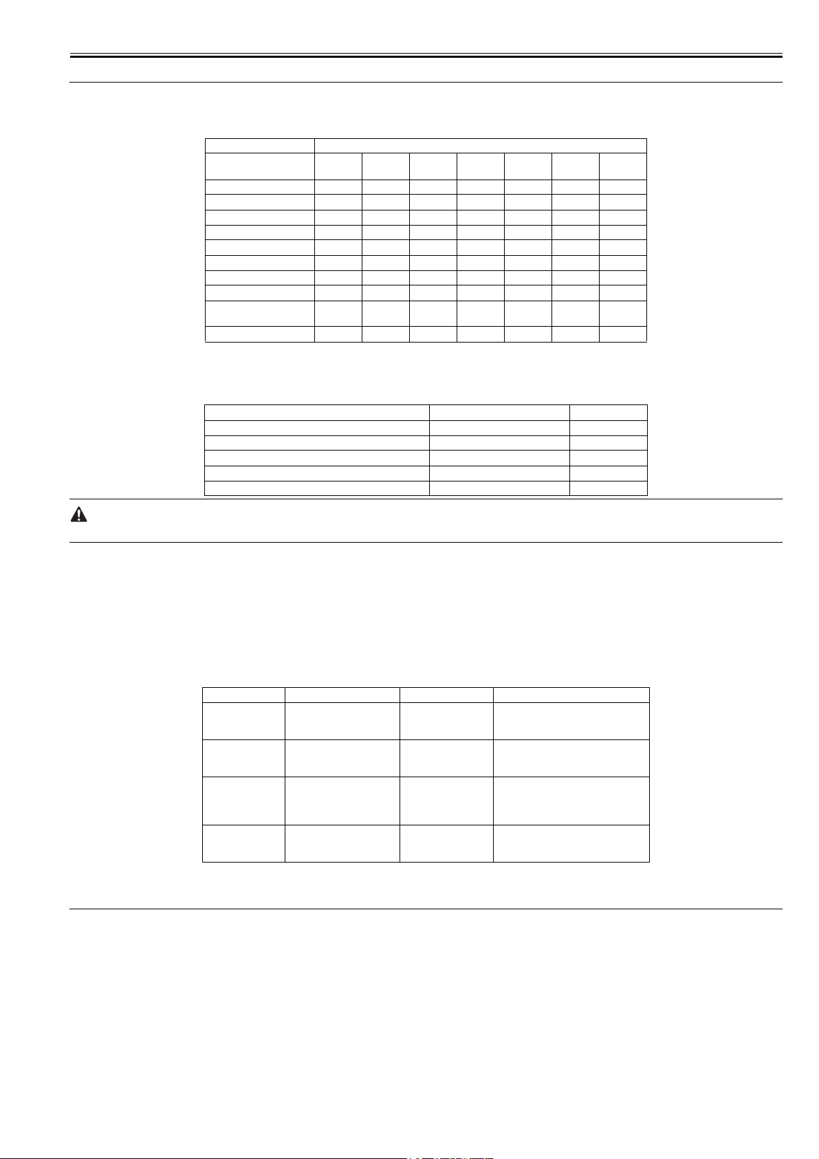
Paper size Plain
A4 ( to 64 g/m2) 2020201220 - -
A4 (65 to 90 g/m2) - 18 10 8 18 - -
B5 (64 to 90 g/m2) 88448- -
A5 (64 to 90 g/m2) 88448- -
A4 (105 to 128 g/m2) - - 18 12 - - -
B5 (105 to 128 g/m2) - - 4 4 - - -
LTR (75 to 90 g/m2) 2121211221 - -
LGL (75 to 90 g/m2)15------
LTR (Bond 75 to 90 g/m2,
105 g/m2)
Envelope ------4
(unit: sheets/min)
1.1.2 Stack Upon Delivery
Plain paper (64 to 90 g/m2) Approx. 60 sheets 1 sheet
Heavy paper (105 to 128 g/m2) Approx. 30 sheets 1 sheet
Transparency Approx. 10 sheets 1 sheet
Label Approx. 10 sheets 1 sheet
Envelope Approx. 10 sheets 1 sheet
T-1-1
Fixing mode
paper
Paper type Face-down Face-up
Plain
paper L
--2112---
Heavy
paper
T-1-2
Heavy
paper H
Transpar
ency
Envelope COM10
0012-5715
0012-0849
The values herein are estimates only and are subject to change for product improvement.
1.1.3 System Requirements for Printer Driver
Operating System
Windows 98/98SE, Windows Me, Windows 2000 Professional, Windows XP
Computer
Any computer on whitch Windows 98, Windows Se, Windows Me, Windows 2000, or Windows XP runs properly.
Hardware Environment
-IBM or IBM-compatible PC
-CD-ROM drive or network environment with the access to CD-ROM
-PC equipped with a USB port and the USB class driver installed
OS CPU RAM Available Free Disk Space
Windows 98
Windows Me
Windows 2000*
Professional
Windows XP*
Intel Pentium 90 MHz or
greater
Intel Pentium 150 MHz or
greater
Intel Pentium 133 MHz or
greater, or compatible micro
processors (up to 2
processors are supported)
Pentium Family 300 MHz or
greater
32 MB of RAM, 64
MB or greater is
recommended
32 MB of RAM, 64
MB or greater is
recommended
64 MB of RAM, 128
MB or greater is
recommended
64 MB of RAM, 128
MB or greater is
recommended
T-1-3
At least 115 MB, 200MB or greater is
recommended
At least 115 MB, 200MB or greater is
recommended
At least 115 MB, 200MB or greater is
recommended
At least 115 MB, 200MB or greater is
recommended
*Log on as a user with adoministrator privileges is recommended.
1.2 Names of Parts
0012-0850
1.2.1 External View
<Front View>
0012-0851
1-1
Chapter 1
[1]
[2]
[3]
[4]
[5]
[6]
[7]
F-1-1
T-1-4
[1] Platen glass cover [5] Front cover
[2] Platen glass [6] Multi-purpose feeder
[3] Operation panel [7] Cassette
[4] Output tray
<Rear View>
1.2.2 Operation panel
F-1-2
T-1-5
[1] USB port
[2] Face up cover
[3] Power socket
[4] Extension cover
[1] [2] [3] [4] [5] [6] [7][8] [9]
[1]
[2]
[3]
[4]
0012-0853
[10] [11]
1-2
Coded
Dial
Redial/
Pause
Hook
COPY FAX SCAN
Image CLASS
Processing/
Data
System
Monitor
MF 3240
OK
Addtional
Function
Enlarge /
Reduce
Error
Density
Image
Quality
Collate /
Clear
2on1
01 02
03 04
05 06
07 R
Address
Book
[21][22][23][24] [20][19] [18][17] [16][15] [14] [13] [12]
F-1-3
T-1-6
[1] Address list button [13] Collate/2on1 key
[2] Practice/Memory [14] image Quality key
ABC DEF
123
JKLGHI MNO
456
TUV
PQRS WXYZ
89
7
0
Tone
SYMBOLS
Stop/Reset
Start
Energy Saver
1.3 Safety
Chapter 1
[3] Copy key [15] Clear key
[4] FAX key [16] Initial setting/Registration
[5] SCAN key [17] (+) key
[6] Error indicator [18] OK key
[7] Exposure key [19] (-) key
[8] Enlarge/Reduce key [20] LCD
[9] Numeric keys [21] Status Monitor key
[10] Stop/Reset key [22] Shortening key
[11] Energy Saver key [23] Hook key
[12] Start key [24] Redial/Pose
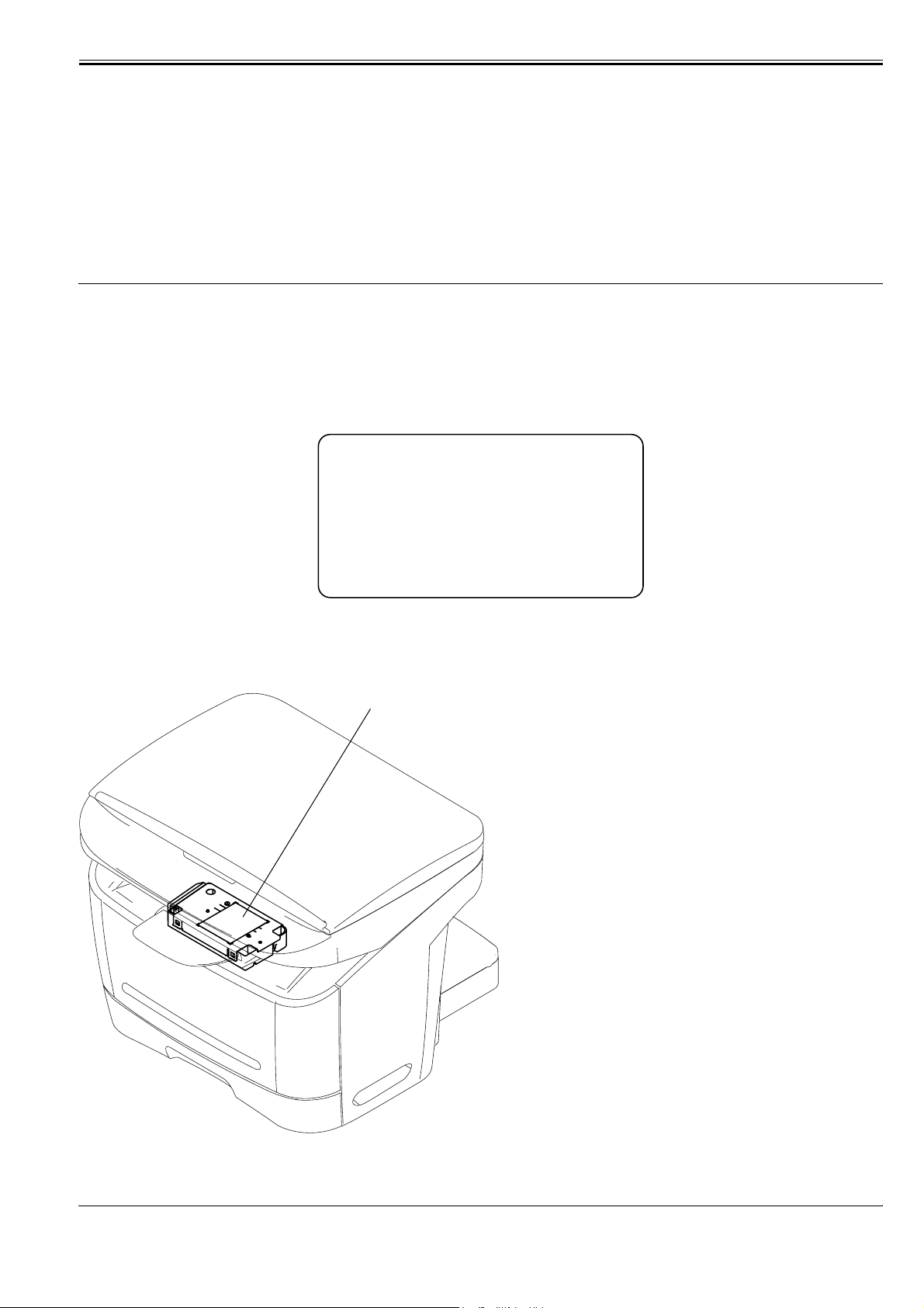
1.3.1 Safety of Laser Light
Laser radiation could be hazardous to the human body. For this reason, laser radiation emitted inside this machine is hermetically sealed within the protective housing and external cover. No radiation can leaak from the machine in the normal operation of the product by the user.
1.3.2 Regulations Under the Center for Devices and Radiological Health (CDRH)
The CDRH of the US Food and Drug Administration put into effect regulations governing the sale of laser products in the US on August 2, 1976. These regulations
apply to all laser products produced on and after August 1, 1976, and a laser product cannot be sold unless it has been certified to comply with the regulations. The
0012-0864
0012-0865
following is the label used to indicate that the product has been certified under the regulations, and all laser products sold in the US must bear the label.
CANON
30-2, SHIMOMARUKO, 3-CHOME, OHTAKU, TOKYO,
146, JAPAN.
MANUFACTURED:
THIS PRODUCT CONFORMS WITH DHHS RADIATION
PERFORMANCE STANDARD 21CFR CHAPTER 1
SUBCHAPTER J.
F-1-4
1.3.3 Handling the Laser Unit
The laser scanner unit emits invisible laser light inside it. If exposed to laser light, the human eye can irreparably be damaged. Never attempt to disassemble the
laser scanner unit. (It is not designed for servicing in the field). The covers around the laser scanner unit are identified by the following label [1].
[1]
0012-0866
F-1-5
1.3.4 Safety of Toner
The machine's toner is a non-toxic material composed of plastic, iron, and small amounts of dye.
0012-0867
1-3

Chapter 1
Do not put the toner into fire. It may explode.
Toner on the Skin or Clothes
1. If your skin or clothes came into contact with toner, wash with water at once.
2. Do not use warm or hot water, which will cause the toner to jell, permanently fusing it with the fibers of the clothes.
3. Do not bring toner into contact with vinyl material. They are likely to react with each other.
1.3.5 Backup Battery
The machine's SCNT PCB are equipped with a lithium battery (1 pc.) serving as a backup source of power in the event of a power shortage or when the power plug
0012-3263
is removed.
LISK OF EXPLOSION IF BATTERY IS REPLACED BY AN INCORRECT TYPE.
DISPOSE OF USED BATTERIES ACCORDING TO THE INSTRUCTIONS.
1-4

Chapter 2 TECHNICAL REFERENCE

Contents
Contents
2.1 Document Feed and Exposure System...........................................................................................................................2-1
2.1.1 Overview/Configuration .............................................................................................................................................................. 2-1
2.1.1.1 Overview ......................................................................................................................................................................................................... 2-1
2.2 Laser Exposure...............................................................................................................................................................2-2
2.2.1 Overview/Configuration .............................................................................................................................................................. 2-2
2.2.1.1 Overview ......................................................................................................................................................................................................... 2-2
2.3 Image Formation ............................................................................................................................................................2-3
2.3.1 Overview/Configuration .............................................................................................................................................................. 2-3
2.3.1.1 Overview ......................................................................................................................................................................................................... 2-3
2.4 Pickup and Feed System ................................................................................................................................................2-4
2.4.1 Overview/Configuration .............................................................................................................................................................. 2-4
2.4.1.1 Overview ......................................................................................................................................................................................................... 2-4
2.4.2 Other Control ............................................................................................................................................................................... 2-4
2.4.2.1 Manual Pickup Control ...................................................................................................................................................................................2-4
2.4.2.2 Cassette Pickup Control ..................................................................................................................................................................................2-4
2.4.3 Detection Jams ............................................................................................................................................................................. 2-5
2.4.3.1 Jam Detection Outline.....................................................................................................................................................................................2-5
2.4.3.1.1 Type so Jams ...........................................................................................................................................................................................2-5
2.4.3.2 Delay Jams ......................................................................................................................................................................................................2-5
2.4.3.2.1 Pickup Delay Jam ....................................................................................................................................................................................2-5
2.4.3.2.2 Delivery Delay Jam .................................................................................................................................................................................2-5
2.4.3.3 Stationary Jams ............................................................................................................................................................................................... 2-5
2.4.3.3.1 Pickup Stationary Jam .............................................................................................................................................................................2-5
2.4.3.3.2 Delivery Stationary Jam ..........................................................................................................................................................................2-5
2.4.3.4 Other Jams....................................................................................................................................................................................................... 2-5
2.4.3.4.1 Wrap Jam................................................................................................................................................................................................. 2-5
2.4.3.4.2 Initial Jam................................................................................................................................................................................................2-5
2.4.3.4.3 Cover Open Jam ...................................................................................................................................................................................... 2-5
2.5 Fixing Unit .....................................................................................................................................................................2-6
2.5.1 Overview/Configuration .............................................................................................................................................................. 2-6
2.5.1.1 Overview ......................................................................................................................................................................................................... 2-6
2.5.2 Protection Function ...................................................................................................................................................................... 2-6
2.5.2.1 Protective Mechanisms ...................................................................................................................................................................................2-6
2.5.2.2 Detecting a Fault in the Fixing Assembly.......................................................................................................................................................2-6
2.6 External and Controls.....................................................................................................................................................2-7
2.6.1 Power Supply ............................................................................................................................................................................... 2-7
2.6.1.1 Backup Battery ................................................................................................................................................................................................ 2-7
2.6.1.1.1 Backup Battery ........................................................................................................................................................................................2-7
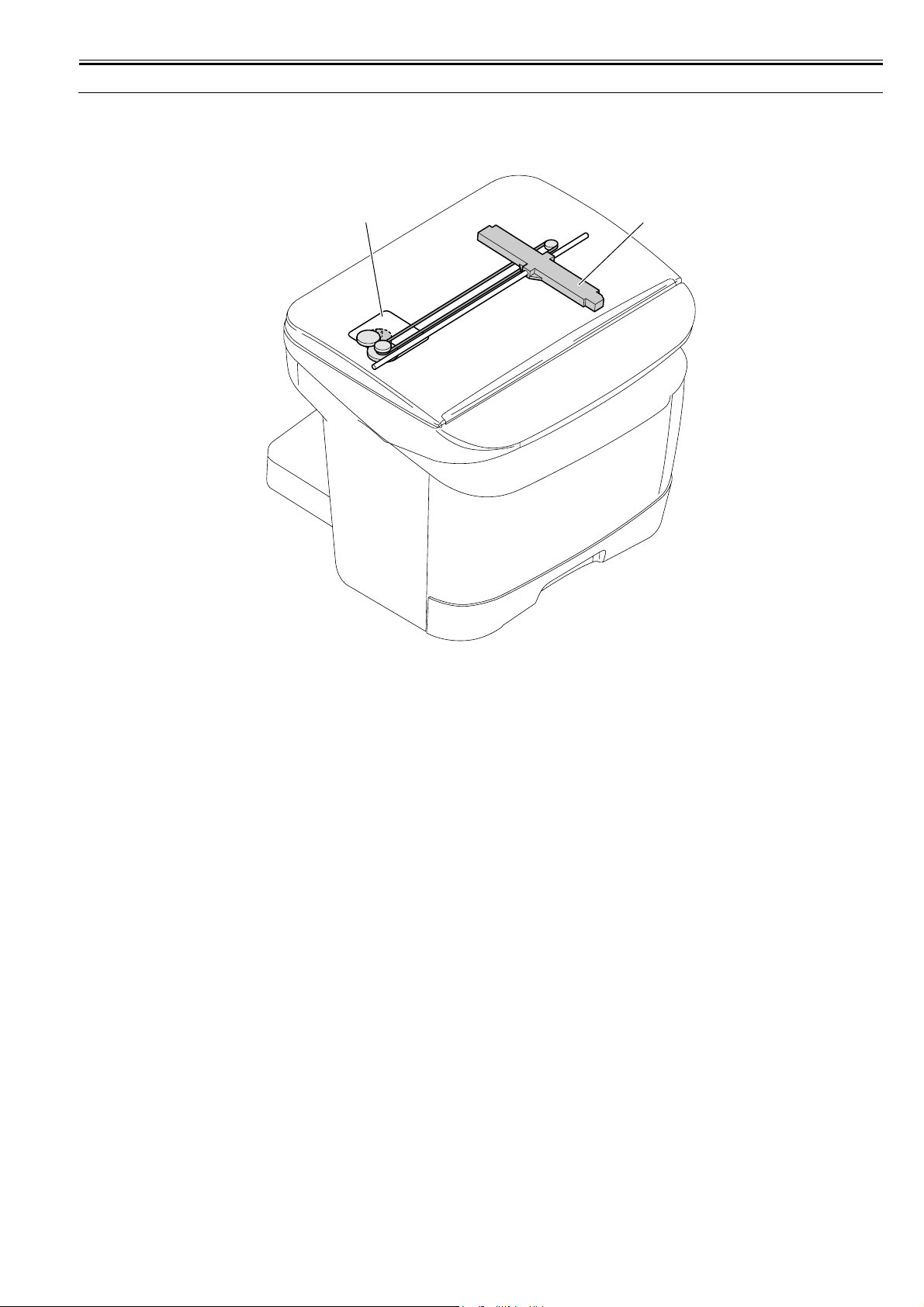
2.1 Document Feed and Exposure System
2.1.1 Overview/Configuration
Chapter 2
2.1.1.1 Overview
0012-0870
[2] [1]
F-2-1
T-2-1
[1] CIS unit
[2] Flatbed motor
The CIS unit driven by the flatbed motor reads out image data of a document on the platen glass.
2-1
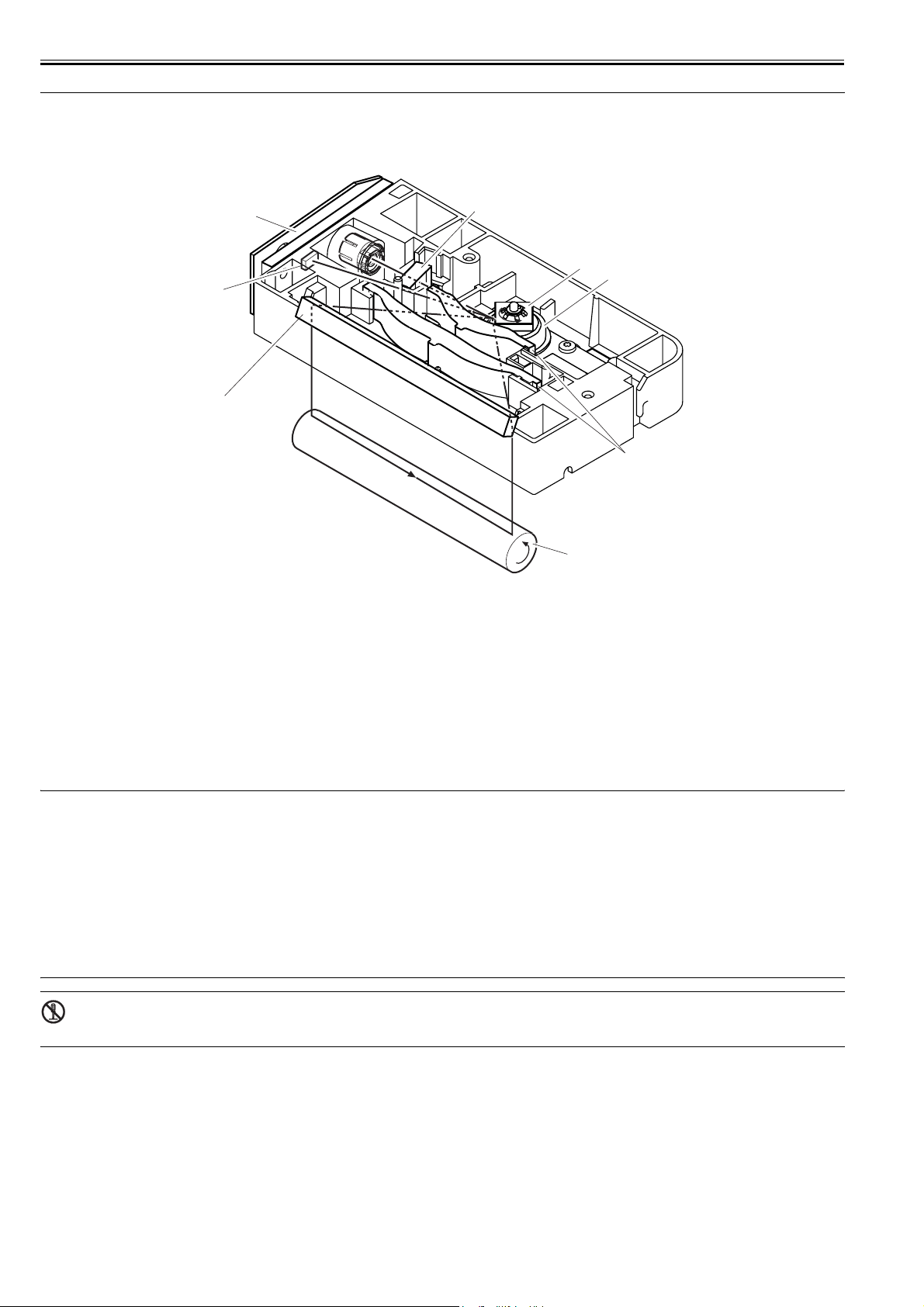
Chapter 2
2.2 Laser Exposure
2.2.1 Overview/Configuration
2.2.1.1 Overview
[1]
[8]
[2]
[3]
F-2-2
T-2-2
[1] Laser driver PCB [5] Imaging lends
[2] BD sensor [6] Scanner motor
[3] Reflecting mirror [7] 4-facet mirror
[4] Photosensitive drum [8] Cylindrical lens
[7]
[4]
0012-0873
[6]
[5]
The machine's laser scanner assembly consists of the laser driver and the scanner motor, which are driven by signals coming from the engine controller.
The laser driver serves to turn on the laser diode according to the laser control signal and video signals from the engine controller.
The laser beam moves thorough the collimator less and the cylindrical lens to reach the 4-facet mirror rotating at a specific speed.
The leaser beam reflected by the 4-facet mirror moves through the imaging lens arranged in front of the 4-facet mirror and the reflecting mirror to reach and focus
on the photosensitive drum.
When the 4-facet mirror rotates at a specific speed, the laser beam scans the photosensitive drum in keeping with the mirror rotation, thus drawing static images on
the photosensitive drum.
MEMO:
BD Fault
The machine identifies a BD fault if it does not detect the /BDI signal within 0.1 sec after the scanner motor is forced to accelerate. It also detects a BD fault
if it does not detect a specific interval of /BDI signals for 2 sec continuously after the scanner motor has reached a specific revolution (number of rotations).
Scanner Fault
If the machine does not detect the /BDI signal 1.4 sc after it has stopped forcing the scanner motor to accelerate, it extends the period of detection by 120 sec;
if it still does not detect a specific interval of /BDI signals, it identifies a scanner fault.
BD Error
The machine identifies a BD error if it does not detect the /BDI signal at a specific interval while the /BDI signal is being generated. It, however, does not
identify a BD error under the following condition:
-the door is identified as being open within 0.2 sec after detection of a BD error.
-a BD fault or a scanner fault is detected after a BD error has been identified.
The laser/scanner unit contains parts that cannot be adjusted in the field. Do not attempt to disassemble the laser/scanner unit.
2-2
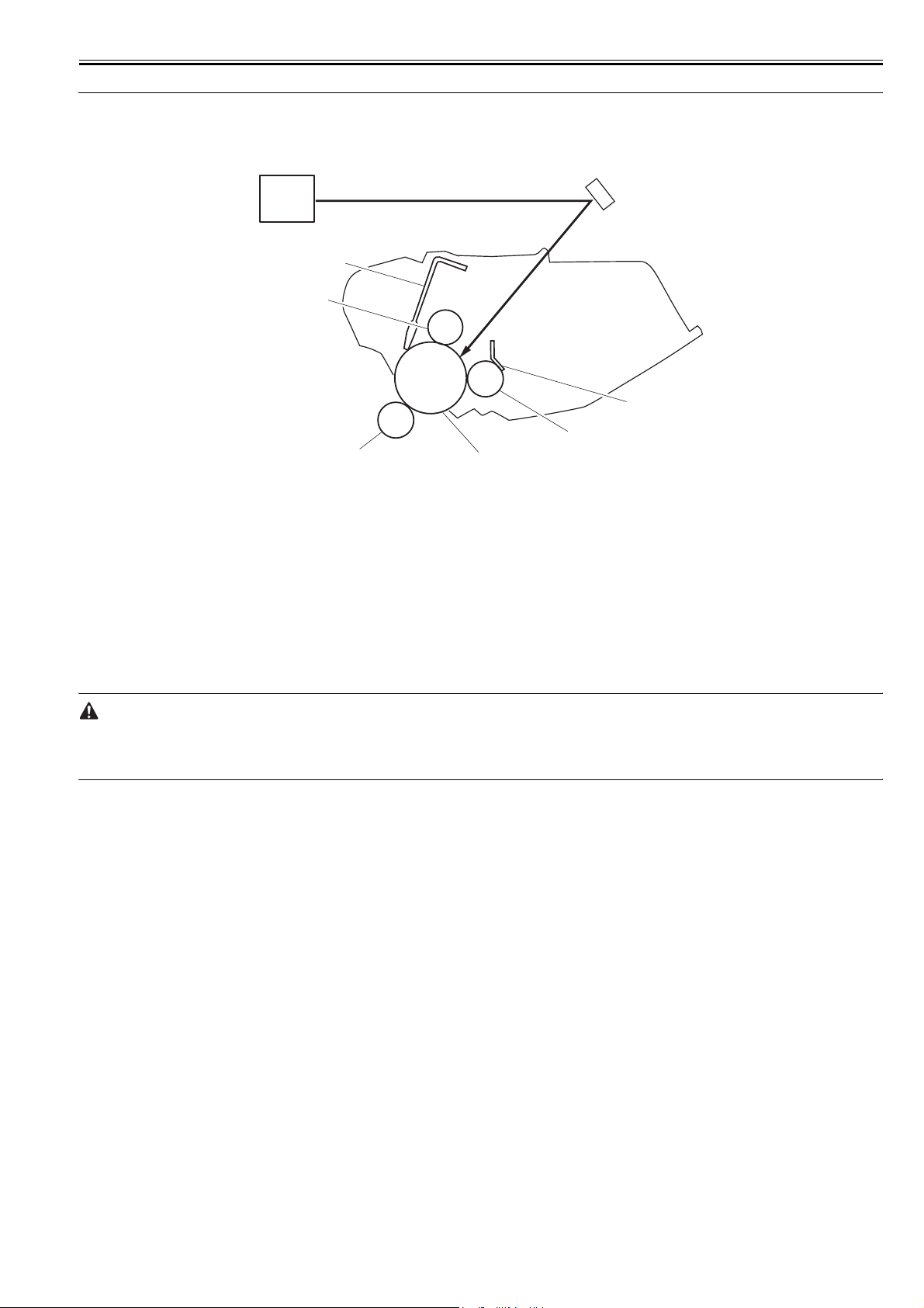
2.3 Image Formation
2.3.1 Overview/Configuration
Chapter 2
2.3.1.1 Overview
[1]
[2]
0012-0874
[8]
[7]
[3]
[4]
[6]
[1] Laser/scanner assembly [5] Photosensitive drum
[2] Laser beam [6] Transfer charging roller
[3] Blade [7] Primary charging roller
[4] Developing cylinder [8] Cleaning blade
In response to a print command, the engine controller turns on the main motor to drive the photosensitive drum, developing cylinder, primary charging roller, and
transfer charging roller.
Thereafter, the machine uses the primary charging roller to charge the surface of the photosensitive drum to an even, negative potential and, at the same time, directs
the laser beam across the surface of the photosensitive drum. (The laser beam is modulated to according to the incoming video signals.)
The image thus formed on the photosensitive drum is a static, latent image; it is turned into a visible image by means of the toner from the developing cylinder. The
resulting toner image is then transferred to paper by the work of the transfer charging roller, and the paper is sent to the fixing assembly. The surface of the photosensitive drum is cleaned by the cleaning blade so that it is free of residual toner; after cleaning, the primary charging roller once again charges the surface to an
even, negative potential to prepare for the formation of a new static, latent image.
[5]
F-2-3
T-2-3
Drum Cover Shutter
If the surface of the photosensitive drum is exposed to strong light, it develops what is know as "photo memory," which can cause white spots or black lines
in images. To protect the drum against light, the machine is equipped with a drum cover shutter. The drum cover shutter must never be opened unless doing
so proves to be absolutely necessary.
2-3
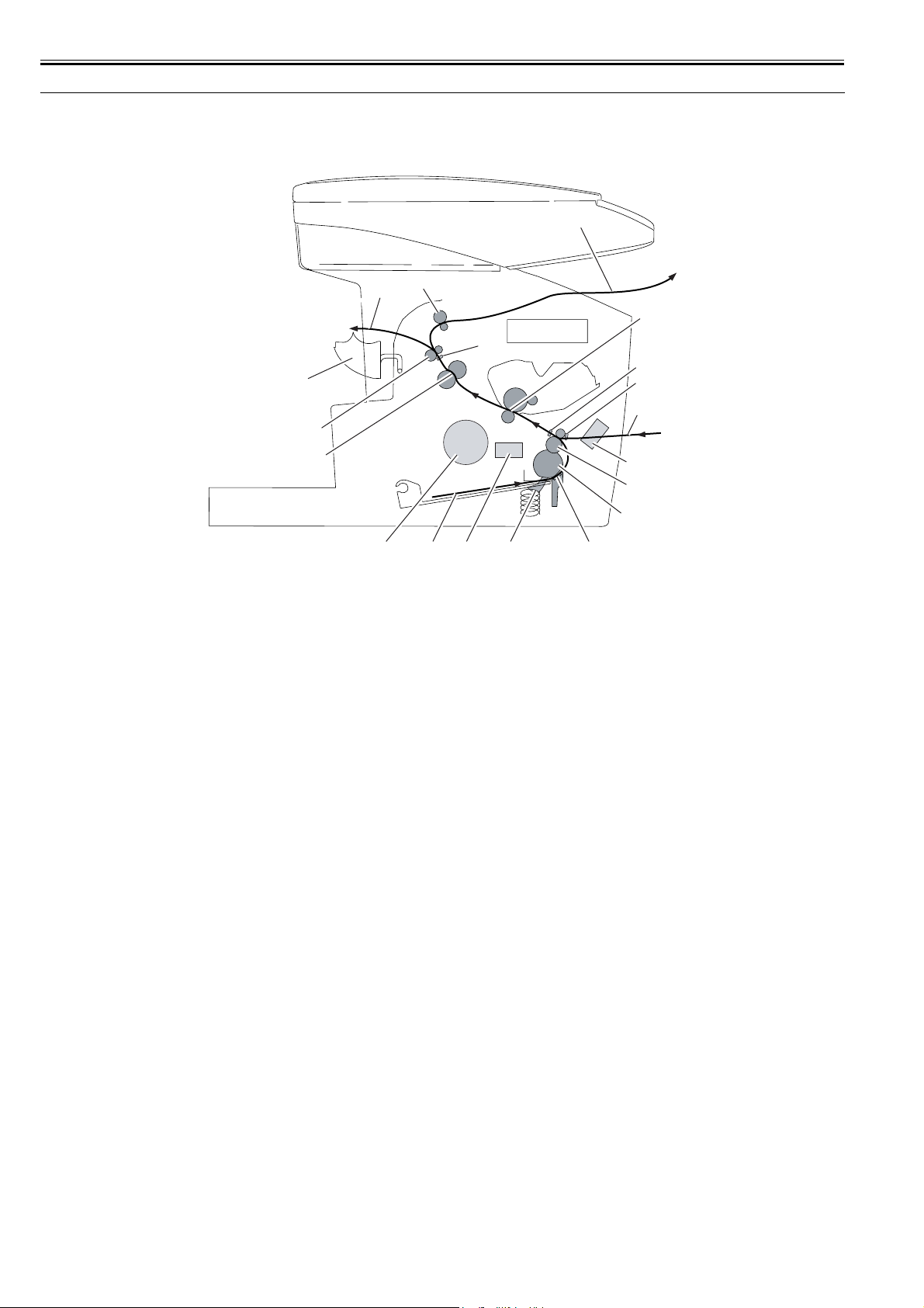
Chapter 2
2.4 Pickup and Feed System
2.4.1 Overview/Configuration
2.4.1.1 Overview
[12]
[11]
[10]
[19]
[9]
[8]
[7]
[1][13] [14] [16]
F-2-4
T-2-4
[1] Cassette feed [12] Face-down delivery
[2] Cassette pickup roller [13] Main motor
[3] Separation pad [14] Cassette pickup solenoid
[4] Manual feed [15] Manual feed pickup solenoid
[5] Feed roller [16] Cassette paper sensor
[6] Transfer assembly (photosensitive drum, transfer
charging roller)
[7] Fixing assembly (fixing film, fixing pressure roller) [18] Top sensor
[8] Delivery roller [19] Delivery sensor
[9] Face-up cover
[10] Face-up delivery
[11] Face-down delivery roller
[17] Manual feed paper sensor
[3]
0012-0892
[6]
[18]
[17]
[4]
[15]
[5]
[2]
Pickup and Feed Operation (from the cassette)
If the cassette paper sensor detects the presence of paper while the absence of paper is identified in the manual feed pickup assembly, the machine picks up paper
from the cassette.
When the main motor operates and the cassette pickup solenoid goes on, the cassette pickup roller makes a single rotation to pick up paper. The paper is then moved
from the transfer assembly to the fixing assembly by the feed roller; it is ultimately delivered outside the machine by the work of the delivery roller.
When the face-up cover is open, the paper is delivered face-up at the rear of the machine. If the face-up cover is closed, on the other hand, the paper is moved along
the feed guide of the cover, and is delivered face-down at the top of the machine by the work of the face-down delivery roller.
Pickup and Feed Operation (from the manual feed section)
When paper is inserted into the pickup assembly, the manual feed paper sensor detects the presence of paper, and the machine uses the feed roller to pick and hold
the leading edge of the paper. When printing starts, the machine turns on the manual feed pickup solenoid to stop the rotation of the feed roller so that the paper
will not move forward until the laser/scanner and the fixing unit become ready for operation. When the laser/scanner and the fixing unit become ready for operation,
the machine turns off the manual feed pickup solenoid to rotate the feed roller, thus moving the paper forward; the operation thereafter is identical to the operation
used for pickup from the cassette.
2.4.2 Other Control
2.4.2.1 Manual Pickup Control
Upon detection of manually inserted paper, the machine drives the main motor for the specified time to feed the paper to the position where it is to be fed between
the feed rollers. In addition, the machine turns on the feed roller (manual pickup) solenoid to stop rotating the feed rollers, thus preventing the manually inserted
paper from being fed askew. With the paper pressed against the feed rollers, the machine drives the main motor and turns off the solenoid to feed the paper between
the feed rollers.
2.4.2.2 Cassette Pickup Control
With the main motor running, the machine turns on the paper pickup solenoid at the specified timing to rotate the pickup rollers. If paper exists over the top sensor
at the start of timing retry, the machine stops cassette pickup control. If paper does not exist, the machine retries cassette pickup control.
0012-1874
0012-1876
2-4

Chapter 2
2.4.3 Detection Jams
2.4.3.1 Jam Detection Outline
2.4.3.1.1 Type so Jams
The machine identifies the following types of jams:
Pickup Delay Jam
The top sensor does not go on within a specific period of time after pickup starts.
Pickup Stationary Jam
The top sensor goes on, but does not go off within a specific period of time.
Delivery Delay Jam
The top sensor goes on, but the delivery sensor does not go on within a specific period of time.
Wrap Jam
The delivery sensor goes on, but it goes off before a specific period of time passes.
Delivery Stationary Jam
The delivery sensor goes on, but it does not go off within a specific period of time.
Initial Jam
The top sensor or the delivery sensor goes on while the main motor is starting to rotate.
Cover Open Jam
0012-0906
The machine identifies a condition in which the front cover is opened while it is moving paper.
2.4.3.2 Delay Jams
2.4.3.2.1 Pickup Delay Jam
If the top sensor does not detect the leading edge of paper within 1.2 sec after the start of pickup operation, the machine initiates pickup operation once gain. The
0012-0907
machine identifies a pickup delay jam if the top sensor does not detect the leading edge of paper within 1.2 sec after the 2nd pickup operation.
2.4.3.2.2 Delivery Delay Jam
The machine identifies a delay jam if the delivery sensor does not detect the leading edge of paper within 1.615 sec after the top sensor has detected the leading
edge of paper.
0012-0908
2.4.3.3 Stationary Jams
2.4.3.3.1 Pickup Stationary Jam
The machine identifies a pickup stationary jam if the top sensor does not detect the absence of paper within 3.575 sec after the top sensor has detected the leading
edge of paper.
0012-0909
2.4.3.3.2 Delivery Stationary Jam
The machine moves to a delivery stationary jam sequence if it does not detect a wrap jam.
The machine identifies a delivery stationary jam if the delivery sensor does not detect the trailing edge of paper for 1.715 sec after the top sensor has detected the
trailing edge of paper.
0012-0911
2.4.3.4 Other Jams
2.4.3.4.1 Wrap Jam
The machine starts a wrap jam detection sequence in 0.1 sec if it does not detect a delivery delay jam.
It identifies a wrap jam if the delivery sensor detects the trailing edge of paper within 1.06 sec after the top sensor has detected the trailing edge of paper.
The term "wrap jam" refers to paper that wraps around the fixing pressure roller; its leading edge passes through the delivery sensor, but it jams thereafter. The
machine is designed to identify such a jam so as to prevent wrapping paper from fully moving into the fixing assembly.
2.4.3.4.2 Initial Jam
The machine identifies an initial jam if the top sensor or the delivery sensor detects the presence of paper when the main motor starts to rotate.
2.4.3.4.3 Cover Open Jam
The machine identifies a cover open jam if it detects that the front cover is open with the top sensor or the delivery sensor detecting the presence of paper (while
paper is being moved or the machine is not running a jam check).
0012-0912
0012-0913
0012-0914
2-5
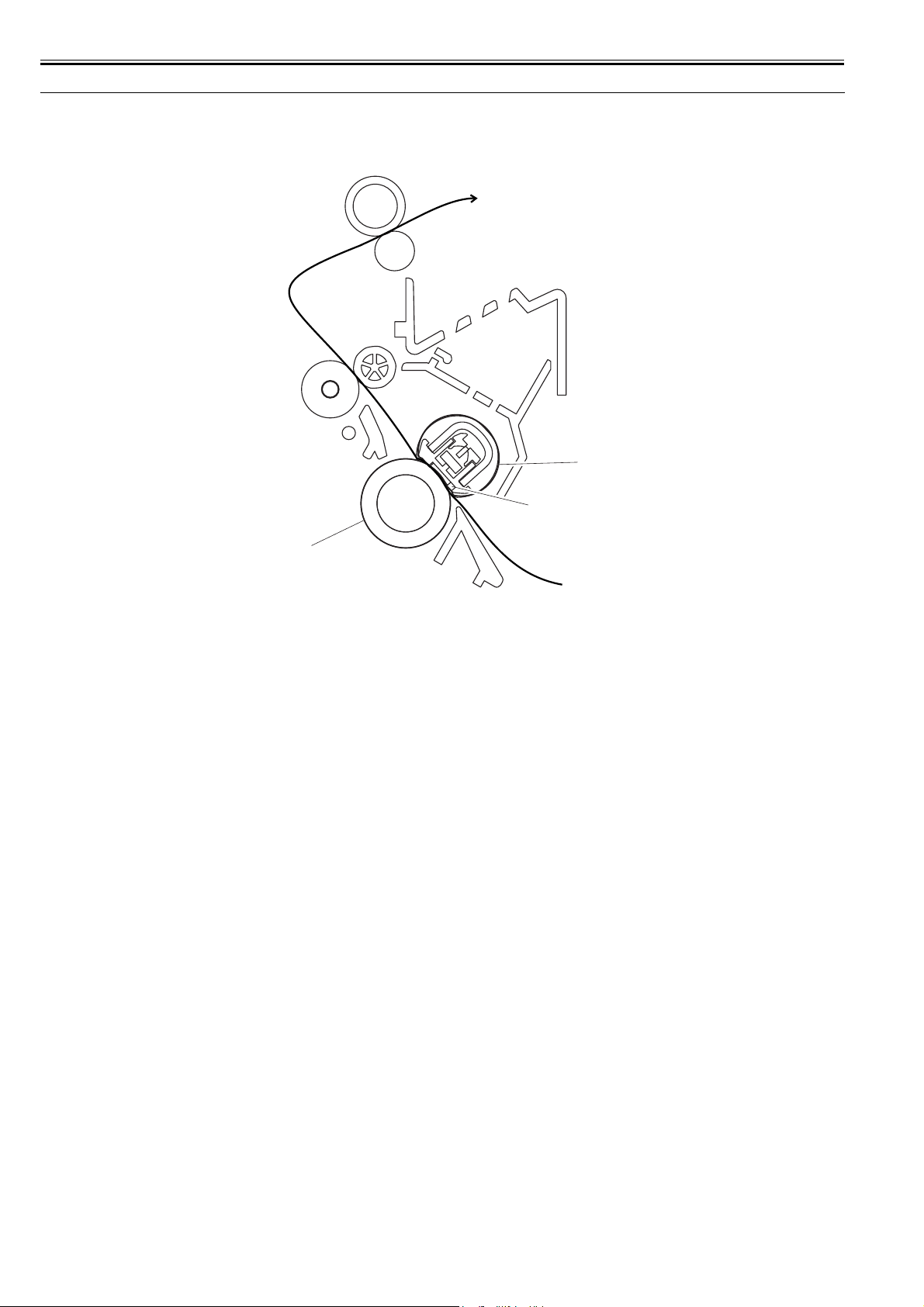
Chapter 2
2.5 Fixing Unit
2.5.1 Overview/Configuration
2.5.1.1 Overview
0012-0915
[1]
[2]
[3]
F-2-5
T-2-5
[1] Fixing film unit
[2] Fixing heater
[3] Pressure roller
The machine's fixing system is an on-demand type, and its fixing assembly consists of the fixing film unit and the pressure roller: the fixing film has a built-in fixing
heater, thermistor, and thermal fuse.
The toner transferred to paper is heated by the fixing heater, which provides heat through the fixing film; the toner is forced under the pressure roller so that it is
fused into the fibers of the paper under both heat and pressure.
2.5.2 Protection Function
2.5.2.1 Protective Mechanisms
The machine is equipped with the following 3 types of protective mechanisms used to prevent its fixing heater from going awry.
1. protective mechanism by the CPU
2. protective mechanism by the fixing heater safety circuit
3. protective mechanism by the thermal fuse
1. Protective Mechanism by the CPU
The machine's CPU monitors the voltage of the fixing heater temperature detection signal from the main thermistor and the sub thermistor at all times, and
it cuts the power to the fixing heater if it finds that the fixing temperature appreciably exceeds a specific level.
When the fixing temperature abnormally increases and the voltage of the fixing heater temperature detection signal from the main thermistor drops to about
0.775 V (equivalent of 235 deg C) or less, the CPU causes the fixing heater drive signal to go Low and turns off the photo triac coupler, thus cutting power
to the fixing heater.
If the temperature of the fixing heater abnormally increases and the voltage of the fixing heater temperature detection signal from the sub thermistor reaches
about 2.779 V (equivalent of 320 deg C) or more, the CPU causes the fixing heater drive signal to go Low and turns off the photo triac couple, thus cutting
off the power to the fixing heater.
2. Protective Mechanism by the Fixing Heater Safety Circuit
The fixing heater safety circuit monitors the voltage of the fixing heater temperature detection signal from the main thermistor and the sub thermistor at all
times.
If the fixing temperature appreciably exceeds a specific level, the machine cuts off the power to the fixing heater regardless of the instructions from the CPU.
When the temperature of the fixing heater increases abnormally and the voltage of the fixing heater temperature detection signal of the main thermistor
reaches about 0.775 V (equivalent of 235 deg C) or less, the output of the comparator turns Low to turn off the relay, thus cutting off the power to the fixing
heater.
Likewise, if the temperature of the fixing heater increases abnormally and the voltage of the fixing heater temperature detection signal of the sub thermistor
reaches about 2.779 V (equivalent of 320 deg C) or more, the output of the comparator turns Low to turn off the transistor, thus turning off the relay and
cutting off the power to the fixing heater regardless of the relay drive signal from the CPU.
3. Protective Mechanism by the Thermal Fuse
If the temperature of the fixing heater increases abnormally and the temperature of the thermal fuse exceeds about 228 deg C, the thermal fuse starts to melt
to cut off the power to the fixing heater.
2.5.2.2 Detecting a Fault in the Fixing Assembly
The CPU identifies a fault in the fixing assembly for the following conditions (a. thorough g.) and operates as described:
1. the CPU causes the fixing heater drive signal to go Low to cut off the power to the fixing heater.
2. the CPU causes the relay drive signal to go Low to turn off the relay.
3. the CPU, if it detects a fault while printing is under way, discharges the paper being picked up or moved at the time, and immediately turns off the main motor,
0012-0916
0012-0917
2-6

Chapter 2
scanner motor, and high-voltage system and puts the printer unit in an error state.
a) the reading of the main thermistor does not exceed 50 deg C within 2.34 sec after the start-up temperature control mechanism is started.
b) the CPU detects that the reading of the main thermistor remains 235 deg C or more for 1 sec continuously while fixing temperature control is under way.
c) the CPU detects that the reading of the main thermistor remains 100 deg C or less for 1.2 sec continuously while paper passage temperature control is under way;
or the CPU detects that the reading of the main thermistor remains 50 deg C or less for 0.3 sec continuously while between-sheets temperature control is under
way.
d) the CPU detects that the reading of the main thermistor remains less than 20 deg C for 0.3 sec continuously while fixing heater temperature control is under way.
e) the temperature of the main thermistor does not exceed 100 deg C within 20 sec after the start of start-up temperature control.
f) the CPU detects that the reading of the sub thermistor remains less than 35 deg C for 0.15 sec continuously while fixing heater temperature control is under way.
g) the CPU detects that the reading of the sub thermistor remains 320 deg C for 0.15 sec continuously while fixing heater temperature control is under way.
2.6 External and Controls
2.6.1 Power Supply
2.6.1.1 Backup Battery
2.6.1.1.1 Backup Battery
The machine's SCNT PCB are equipped with a lithium battery (1 pc.) serving as a backup source of power in the event of a power shortage or when the power plug
is removed.
SCNT PCB litium battery (3V,220mAh)
Life 5yr or more (with power plug removed)
Replacement not possible in the field on its own.
T-2-6
0012-3264
LISK OF EXPLOSION IF BATTERY IS REPLACED BY AN INCORRECT TYPE.
DISPOSE OF USED BATTERIES ACCORDING TO THE INSTRUCTIONS.
2-7

Chapter 3 DISASSEMBLY AND ASSEMBLY

Contents
Contents
3.1 EXTERNAL AND CONTROLS SYSTEM..................................................................................................................3-1
3.1.1 Front Cover .................................................................................................................................................................................. 3-1
3.1.1.1 Removing the front cover................................................................................................................................................................................3-1
3.1.2 Rear Cover ................................................................................................................................................................................... 3-1
3.1.2.1 Removing the Cassette .................................................................................................................................................................................... 3-1
3.1.2.2 Removing the front cover................................................................................................................................................................................3-1
3.1.2.3 Removing the right cover ................................................................................................................................................................................3-1
3.1.2.4 Removing the left cover ..................................................................................................................................................................................3-1
3.1.2.5 Removing the rear cover ................................................................................................................................................................................. 3-1
3.1.3 Top Cover .................................................................................................................................................................................... 3-2
3.1.3.1 Removing the Cassette .................................................................................................................................................................................... 3-2
3.1.3.2 Removing the front cover................................................................................................................................................................................3-2
3.1.3.3 Removing the right cover ................................................................................................................................................................................3-2
3.1.3.4 Removing the left cover ..................................................................................................................................................................................3-2
3.1.3.5 Removing the rear cover ................................................................................................................................................................................. 3-2
3.1.3.6 Removing the Scanner Unit ............................................................................................................................................................................3-2
3.1.3.7 Removing the top cover ..................................................................................................................................................................................3-3
3.1.4 Right Cover .................................................................................................................................................................................. 3-3
3.1.4.1 Removing the Cassette .................................................................................................................................................................................... 3-3
3.1.4.2 Removing the front cover................................................................................................................................................................................3-3
3.1.4.3 Removing the right cover ................................................................................................................................................................................3-3
3.1.5 Left Cover .................................................................................................................................................................................... 3-3
3.1.5.1 Removing the Cassette .................................................................................................................................................................................... 3-3
3.1.5.2 Removing the left cover ..................................................................................................................................................................................3-3
3.1.6 Operation Panel Unit.................................................................................................................................................................... 3-4
3.1.6.1 Removung the Cassette ...................................................................................................................................................................................3-4
3.1.6.2 Removing the front cover................................................................................................................................................................................3-4
3.1.6.3 Removing the right cover ................................................................................................................................................................................3-4
3.1.6.4 Removing the left cover ..................................................................................................................................................................................3-4
3.1.6.5 Removing the rear cover ................................................................................................................................................................................. 3-4
3.1.6.6 Removing the Scanner Unit ............................................................................................................................................................................3-5
3.1.6.7 Removing the Board Unit ...............................................................................................................................................................................3-5
3.1.6.8 Removing the Operation Panel Unit ............................................................................................................................................................... 3-5
3.1.7 SCNT Board................................................................................................................................................................................. 3-6
3.1.7.1 Removing the Cassette .................................................................................................................................................................................... 3-6
3.1.7.2 Removing the front cover................................................................................................................................................................................3-6
3.1.7.3 Removing the right cover ................................................................................................................................................................................3-6
3.1.7.4 Removing the left cover ..................................................................................................................................................................................3-6
3.1.7.5 Removing the rear cover ................................................................................................................................................................................. 3-6
3.1.7.6 Removing the Scanner Unit ............................................................................................................................................................................3-6
3.1.7.7 Removing the SCNT Board ............................................................................................................................................................................ 3-7
3.1.8 ECNT Board ................................................................................................................................................................................ 3-7
3.1.8.1 Removing the Cassette .................................................................................................................................................................................... 3-7
3.1.8.2 Removing the front cover................................................................................................................................................................................3-7
3.1.8.3 Removing the left cover ..................................................................................................................................................................................3-7
3.1.8.4 Removing the ECNT Board ............................................................................................................................................................................3-7
3.1.9 Power Supply PCB ...................................................................................................................................................................... 3-8
3.1.9.1 Removing the Cassette .................................................................................................................................................................................... 3-8
3.1.9.2 Removing the front cover................................................................................................................................................................................3-8
3.1.9.3 Removing the right cover ................................................................................................................................................................................3-8
3.1.9.4 Removing the left cover ..................................................................................................................................................................................3-8
3.1.9.5 Removing the rear cover ................................................................................................................................................................................. 3-8
3.1.9.6 Removing the Power Supply Shield Plate ......................................................................................................................................................3-8
3.1.9.7 Removing the Power Supply Assembly .......................................................................................................................................................... 3-9

Contents
3.1.9.8 Removing the Power Supply Board................................................................................................................................................................ 3-9
3.1.10 High-voitage Power Supply PCB .............................................................................................................................................. 3-9
3.1.10.1 Removing the Cassette.................................................................................................................................................................................. 3-9
3.1.10.2 Removing the front cover ............................................................................................................................................................................. 3-9
3.1.10.3 Removing the right cover ............................................................................................................................................................................. 3-9
3.1.10.4 Removing the left cover.............................................................................................................................................................................. 3-10
3.1.10.5 Removing the rear cover ............................................................................................................................................................................. 3-10
3.1.10.6 Removing the Power Supply Shield Plate .................................................................................................................................................. 3-10
3.1.10.7 Removing the Power Supply Board............................................................................................................................................................ 3-10
3.1.10.8 Removing the High-Voltage Power Supply Board..................................................................................................................................... 3-11
3.1.11 Top Sensor ............................................................................................................................................................................... 3-11
3.1.11.1 Removing the Cassette................................................................................................................................................................................ 3-11
3.1.11.2 Removing the front cover ........................................................................................................................................................................... 3-11
3.1.11.3 Removing the right cover ........................................................................................................................................................................... 3-11
3.1.11.4 Removing the left cover.............................................................................................................................................................................. 3-11
3.1.11.5 Removing the rear cover ............................................................................................................................................................................. 3-12
3.1.11.6 Removing the Scanner Unit ........................................................................................................................................................................ 3-12
3.1.11.7 Removing the top cover .............................................................................................................................................................................. 3-12
3.1.11.8 Removing the Right Frame ......................................................................................................................................................................... 3-12
3.1.11.9 Removing the Plate ..................................................................................................................................................................................... 3-12
3.1.11.10 Removing the Left Frame ......................................................................................................................................................................... 3-13
3.1.11.11 Removing the Power Supply Shield Plate ................................................................................................................................................ 3-13
3.1.11.12 Removing the Power Supply Assembly ................................................................................................................................................... 3-13
3.1.11.13 Removing the top sensor........................................................................................................................................................................... 3-13
3.1.12 Paper Delivery Sensor.............................................................................................................................................................. 3-14
3.1.12.1 Removing the Cassette................................................................................................................................................................................ 3-14
3.1.12.2 Removing the front cover ........................................................................................................................................................................... 3-14
3.1.12.3 Removing the right cover ........................................................................................................................................................................... 3-14
3.1.12.4 Removing the left cover.............................................................................................................................................................................. 3-14
3.1.12.5 Removing the rear cover ............................................................................................................................................................................. 3-14
3.1.12.6 Removing the Power Supply Shield Plate .................................................................................................................................................. 3-14
3.1.12.7 Removing the Scanner Unit ........................................................................................................................................................................ 3-15
3.1.12.8 Removing the Plate ..................................................................................................................................................................................... 3-15
3.1.12.9 Removing the Paper Delivery Sensor ......................................................................................................................................................... 3-15
3.2 Document Feed/Exposure System............................................................................................................................... 3-15
3.2.1 Scanner Unit............................................................................................................................................................................... 3-15
3.2.1.1 Removing the Cassette.................................................................................................................................................................................. 3-15
3.2.1.2 Removing the front cover ............................................................................................................................................................................. 3-15
3.2.1.3 Removing the right cover ............................................................................................................................................................................. 3-16
3.2.1.4 Removong the left cover ............................................................................................................................................................................... 3-16
3.2.1.5 Removing the rear cover ............................................................................................................................................................................... 3-16
3.2.1.6 Removing the Scanner Unit .......................................................................................................................................................................... 3-16
3.2.2 Scanner Cover Unit.................................................................................................................................................................... 3-17
3.2.2.1 Removing the Cassette.................................................................................................................................................................................. 3-17
3.2.2.2 Removing the front cover ............................................................................................................................................................................. 3-17
3.2.2.3 Removing the right cover ............................................................................................................................................................................. 3-17
3.2.2.4 Removing the left cover ................................................................................................................................................................................ 3-17
3.2.2.5 Removing the rear cover ............................................................................................................................................................................... 3-17
3.2.2.6 Removing the Scanner Unit .......................................................................................................................................................................... 3-17
3.2.2.7 Removing the Operation Panel Unit............................................................................................................................................................. 3-18
3.2.2.8 Scanner cover unit ........................................................................................................................................................................................ 3-18
3.2.3 Contact Sensor ........................................................................................................................................................................... 3-18
3.2.3.1 Removing the Cassette.................................................................................................................................................................................. 3-18
3.2.3.2 Removing the front cover ............................................................................................................................................................................. 3-18
3.2.3.3 Removing the right cover ............................................................................................................................................................................. 3-18
3.2.3.4 Removing the left cover ................................................................................................................................................................................ 3-19
3.2.3.5 Removing the rear cover ............................................................................................................................................................................... 3-19
3.2.3.6 Removing the Scanner Unit .......................................................................................................................................................................... 3-19
3.2.3.7 Removing the Operation Panel Unit............................................................................................................................................................. 3-19
3.2.3.8 Removing the Scanner Cover Unit ............................................................................................................................................................... 3-20
3.2.3.9 Removing the Flatbed Motor Unit................................................................................................................................................................ 3-20

Contents
3.2.3.10 Removing the Contact Sensor..................................................................................................................................................................... 3-20
3.2.4 Flatbed Motor Unit .................................................................................................................................................................... 3-20
3.2.4.1 Removing the Cassette .................................................................................................................................................................................. 3-20
3.2.4.2 Removing the front cover.............................................................................................................................................................................. 3-20
3.2.4.3 Removing the right cover ..............................................................................................................................................................................3-21
3.2.4.4 Removing the left cover ................................................................................................................................................................................3-21
3.2.4.5 Removing the rear cover ...............................................................................................................................................................................3-21
3.2.4.6 Removing the Scanner Unit .......................................................................................................................................................................... 3-21
3.2.4.7 Removing the Operation Panel Unit .............................................................................................................................................................3-22
3.2.4.8 Removing the Scanner Cover Unit ...............................................................................................................................................................3-22
3.2.4.9 Removing the Flatbed Motor Unit ................................................................................................................................................................3-22
3.3 LASER EXPOSURE SYSTEM...................................................................................................................................3-22
3.3.1 Laser/Scanner Unit..................................................................................................................................................................... 3-22
3.3.1.1 Removing the Cassette .................................................................................................................................................................................. 3-22
3.3.1.2 Removing the front cover.............................................................................................................................................................................. 3-22
3.3.1.3 Removing the right cover ..............................................................................................................................................................................3-23
3.3.1.4 Removing the left cover ................................................................................................................................................................................3-23
3.3.1.5 Removing the rear cover ...............................................................................................................................................................................3-23
3.3.1.6 Removing the Scanner Unit .......................................................................................................................................................................... 3-23
3.3.1.7 Removing the top cover ................................................................................................................................................................................ 3-24
3.3.1.8 Removing the Laser/Scanner Unit ................................................................................................................................................................3-24
3.4 IMAGE FORMATION SYSTEM ...............................................................................................................................3-24
3.4.1 Transfer Charging Roller ........................................................................................................................................................... 3-24
3.4.1.1 Removing the Transfer Charging Roller.......................................................................................................................................................3-24
3.5 PICKUP AND FEEDING SYSTEM...........................................................................................................................3-24
3.5.1 Cassette Pickup Roller ............................................................................................................................................................... 3-24
3.5.1.1 Removing the Cassette .................................................................................................................................................................................. 3-24
3.5.1.2 Removing the front cover.............................................................................................................................................................................. 3-24
3.5.1.3 Removing the right cover ..............................................................................................................................................................................3-25
3.5.1.4 Removing the left cover ................................................................................................................................................................................3-25
3.5.1.5 Removing the rear cover ...............................................................................................................................................................................3-25
3.5.1.6 Removing the Scanner Unit .......................................................................................................................................................................... 3-25
3.5.1.7 Removing the top cover ................................................................................................................................................................................ 3-25
3.5.1.8 Removing the Right Frame ...........................................................................................................................................................................3-26
3.5.1.9 Removing the Plate .......................................................................................................................................................................................3-26
3.5.1.10 Removing the Left Frame ...........................................................................................................................................................................3-26
3.5.1.11 Removing the Power Supply Shield Plate ..................................................................................................................................................3-26
3.5.1.12 Removing the Power Supply Assembly......................................................................................................................................................3-26
3.5.1.13 Removing the Gear Unit .............................................................................................................................................................................3-27
3.5.1.14 Removing the Tooth-Missing Gear.............................................................................................................................................................3-27
3.5.2 Cassette Pickup Solenoid ........................................................................................................................................................... 3-27
3.5.2.1 Removing the Cassette .................................................................................................................................................................................. 3-27
3.5.2.2 Removing the front cover.............................................................................................................................................................................. 3-27
3.5.2.3 Removing the right cover ..............................................................................................................................................................................3-27
3.5.2.4 Removing the left cover ................................................................................................................................................................................3-28
3.5.2.5 Removing the rear cover ...............................................................................................................................................................................3-28
3.5.2.6 Removing the Scanner Unit .......................................................................................................................................................................... 3-28
3.5.2.7 Removing the top cover ................................................................................................................................................................................ 3-28
3.5.2.8 Removing the Right Frame ...........................................................................................................................................................................3-29
3.5.2.9 Removing the Plate .......................................................................................................................................................................................3-29
3.5.2.10 Removing the Left Frame ...........................................................................................................................................................................3-29
3.5.2.11 Removing the Power Supply Shield Plate ..................................................................................................................................................3-29
3.5.2.12 Removing the Power Supply Assembly......................................................................................................................................................3-29
3.5.2.13 Removing the Cassette Pickup Solenoid.....................................................................................................................................................3-30
3.5.3 Cassette Separation Pad ............................................................................................................................................................. 3-30
3.5.3.1 Removing the Cassette .................................................................................................................................................................................. 3-30
3.5.3.2 Removing the Rear of the Cassette ...............................................................................................................................................................3-30
3.5.3.3 Removing the Cassette Separation Pad ......................................................................................................................................................... 3-30
3.5.4 Paper Feed Roller....................................................................................................................................................................... 3-30
3.5.4.1 Removing the Cassette .................................................................................................................................................................................. 3-30
 Loading...