

Canon DU7-1178-000, Kit-H1, Kit-E1, Kit-C1 Service Manual
SERVICE
MANUAL
Multi PDL
Printer Kit-H1
Universal Send Kit-E1
Universal Send PDF
Enhancement Kit-C1
COPYRIGHT ©2005 CANON INC. CANON Multi PDL Printer Kit-H1 REV. 0 PRINTED IN U.S.A.
DU7-1178-000
NOVEMBER 2005
REV. 0

Application
This manual has been issued by Canon Inc. for qualified persons to learn technical theory, insta llati on, ma intenance, and repair
of products. This manual covers all localities where the products are sold. For this reason, there may be information in this
manual that does not apply to your locality.
Corrections
This manual may contain technical inaccuracies or typographical errors due to improvements or changes in products. When
changes occur in applicable products or in the contents of this manual, Canon will release technical information as the need
arises. In the event of major changes in the contents of this manual over a long or short period, Canon will issue a new edition
of this manual.
The following paragraph does not apply to any countries where such provisions are inconsistent with local law.
Trademarks
The product names and company names used in this manual are the registered trademarks of the individual companies.
Copyright
This manual is copyrighted with all rights reserved. Under the copyright laws, this manual may not be copied, reproduced or
translated into another language, in whole or in part, without the written consent of Canon Inc.
COPYRIGHT © 2001 CANON INC.
Printed in Japan
Caution
Use of this manual should be strictly supervised to avoid disclosure of confidential information.
Symbols Used
This documentation uses the following symbols to indicate special information:
Symbol Description
Indicates an item of a non-specific nature, possibly classified as Note, Caution, or Warning.
Indicates an item requiring care to avoid electric shocks.
Indicates an item requiring care to avoid combustion (fire).
Indicates an item prohibiting disassembly to avoid electric shocks or problems.
Indicates an item requiring disconnection of the power plug from the electric outlet.
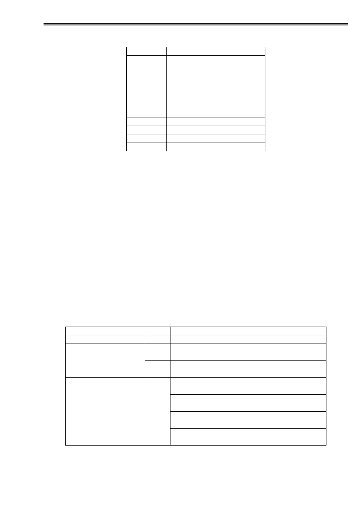
Introduction
Memo
REF.
Indicates an item intended to provide notes assisting the understanding of the topic in question.
Indicates an item of reference assisting the understanding of the topic in question.
Provides a description of a service mode.
Provides a description of the nature of an error indication.

Introduction
The following rules apply throughout this Service Manual:
1. Each chapter contains sections explaining the purpose of specific functions and the relationship between electrical and mechanical systems with reference to the timing of operation.
In the diagrams, represents the path of mechanical drive; where a signal name accompanies
the symbol , the arrow indicates the direction of the electric signal.
The expression "turn on the power" means flipping on the power switch, closing the front door, and
closing the delivery unit door, which results in supplying the machine with power.
2. In the digital circuits, '1'is used to indicate that the voltage level of a given signal is "High", while '0' is used to indicate "Low".(The voltage value, however, differs from circuit to circuit.) In addition, the asterisk (*) as in "DRMD*" indicates that the DRMD signal goes on when '0'.
In practically all cases, the internal mechanisms of a microprocessor cannot be checked in the field.
Therefore, the operations of the microprocessors used in the machines are not discussed: they are
explained in terms of from sensors to the input of the DC controller PCB and from the output of the
DC controller PCB to the loads.
The descriptions in this Service Manual are subject to change without notice for product improvement
or other purposes, and major changes will be communicated in the form of Service Information bulletins.
All service persons are expected to have a good understanding of the contents of this Service Manual
and all relevant Service Information bulletins and be able to identify and isolate faults in the machine."

Contents
Contents
Chapter 1 Specifications
1.1 Specifications ..................................................................................................................................................1- 1
1.1.1 UFR II Printer Driver................................................................................................................................1- 1
1.1.2 UFR II FONT HANDLING.......................................................................................................................1- 3
1.1.3 PS/PCL Printer Driver.............................................................................................................................1- 3
1.1.4 PCL FONT HANDLING ................................ ............................................................................... ........... 1- 6
1.1.5 PS FONT HANDLING............................................................................................................................. 1- 6
1.1.6 Device Finishing.......................................................................................................................................1- 7
Chapter 2 Functions
2.1 Basic Function........................................................................................................................................... ...... 2- 1
2.1.1 Canon Driver Information Assist Service (DIAS)................................................................................2- 1
2.1.2 FTP Printing..............................................................................................................................................2- 2
2.1.3 Halftone Settings......................................................................................................................................2- 4
2.1.4 Secured Print Jobs.................................................................................................................................. 2- 4
2.1.5 Up to 50 mm of Gutter ............................................................................................................................2- 7
2.1.6 Processing on System............................................................................................................................2- 7
2.1.7 Print Pause...............................................................................................................................................2- 8
2.1.8 Format Settings........................................................................................................................................ 2- 8
2.1.9 Staple & Group.........................................................................................................................................2- 9
2.1.10 PS_EPS file Output...............................................................................................................................2- 9
2.2 Changed Function........................................................................................................................................ 2- 10
2.2.1 Device Settings......................................................................................................................................2- 10
2.2.2 Custom Paper Size Settings Unit(Millimeter-Inch)............................................................ ...............2- 11
2.2.3 Application Color Matching Priority............................................................. ........................................2- 11
2.2.4 Objective(PCL): Halftones(PS):.............................................................................. .............................2- 12
2.3 New Function.................................................................................................................................................2- 13
2.3.1 Custom Paper Size Settings(Long Paper)........................................ ................................................. 2- 13
2.3.2 Finishing(Number of Copies for Offset).............................................................. ................................2- 13
2.3.3 Proof Print...................................................................................................................................... .........2- 14
2.3.4 Perfect Binding.......................................................................................................................................2- 14
2.3.5 Use Creep(Displacement)Correction.................. ........................................ ........................................2- 16
2.3.6 Countermeasure against Memory full.............................................................................. ..................2- 16
2.3.7 Use Skip Blank Pages Mode................................................... ........................................ ....................2- 17
2.3.8 Line Refinement................................................................................................................................. .... 2- 18
2.3.9 Front/Back Cover Settings ...................................... .............................................................................2- 19
Chapter 3 Installation
3.1 Checking components...................................................................................................................................3- 1
3.1.1 Checking accessories.............................................................................................................................3- 1
3.2 Installation procedure..................................................................................................................................... 3- 1
3.2.1 Installation procedure..............................................................................................................................3- 1

Chapter 1
Specifications

Contents
Contents
1.1 Specifications .....................................................................................................................................................1-1
1.1.1 UFR II Printer Driver..................................................................................................................................1-1
1.1.2 UFR II FONT HANDLING........................................................................................................................ 1-3
1.1.3 PS/PCL Printer Driver.................................................................................................................................1-3
1.1.4 PCL FONT HANDLING................................................................... ..................................... ....................1-6
1.1.5 PS FONT HANDLING........................................................ ....................................... ................................1-6
1.1.6 Device Finishing...................................... ........................................ ............................................................1-7
1.1 Specifications
Chapter 1
1.1.1 UFR II Printer Driver
0010-7471
The UFR II assigns print processing loads to the print driver and the print controller for high-speed, lowcost outputs.
Advantages
- While the features are enhanced, the memory usage can be saved supporting both page and band descriptions.
- Balancing the data processing loads of the driver and controller allows high-speed outputs.
T-1-1
Specification
UFR II
Data processing 600/1200dpi
Effective print main scanning:2.5mm
sub scanning:Top 4.5mm, Bottom 2.5mm
Supported operating systems
T-1-2
Windows 2000 Professional/Server/Advanced Server
Windows XP Home Edition/Professional Edition(32 bit)
Microsoft Windows XP Professional x64 Edition (64 bit)
Microsoft Windows Server 2003 (32 bit)
Microsoft Windows Server 2003 x64 Edition (64 bit)
Mac OS X v10.2.8-V10.4.2
The UFR II print driver requires 5.0 mm of the top, bottom, left, and right margins.
-Even if Print with Upper Left of Sheet as Starting Point option is selected, marginal areas of the data for
a page are missing in some print results. To solve this problem, adjust the scaling so that the data fit into
the printable area and print the data again.
Non-default paper:
T-1-3
UFR II
Effective print area(mm) End of Paper(mm)
Main scaning Sub scaning Main scaning Sub scaning
Custom Size Minimum 90.00 138.00 5.00 5.00
Custom Size Maximum 287.00 422 .00 5.00 5.00
Long sheet Minimum 90.00 423.00 5.00 5.00
Long sheet Maximum 287.00 622.00 5.00 5.00
0mm Mode
T-1-4
0mm Mode
Effective print area(mm) End of Paper(mm)
Main scaning Sub scaning Main scaning Sub scaning
Custom Size Minimum 95.00 141.00 2.50
Custom Size Maximum 292.00 425.00 2.50
Long sheet Minimum 95.00 426.00 2.50
Long sheet Maximum 292.00 623.00 2.50
Top 2.50
Bottom 2.50
Top 2.50
Bottom 2.50
Top 2.50
Bottom 2.50
Top 2.50
Bottom 2.50
1-1

Chapter 1
Paper Size:
T-1-5
Paper Name Paper Size (mm)
Width length
A3 297.0 420.0
A4 210.0 297.0
A5 148.5 210.0
B4 257.0 364.0
B5 182.0 257.0
11 x 17 279.4 431.8
LEGAL 215.9 355.6
LETTER 215.9 279.4
STATEMENT 139.7 215.9
EXECUTIVE 184.2 266.7
Area-Specific Paper Sizes:
In addition to default paper sizes (A4/LTR) and user-defined paper sizes, the printer driver supports areaspecific paper sizes (e.g., Officio), and it handles these area-specific paper sizes as user-defined paper sizes, requiring the user to register them in advance of use. To do so, see the instructions on registering userdefined paper sizes for individual operating systems.
When an area-specific paper size is manually set up under [Form to Tray Assignment] of the driver UI, or
if the size obtained by running dynamic configuration happens to be an area-specific paper size, the driver
operates in the corresponding mode. After performing all associated internal operations, the driver runs a
check of area-specific paper sizes stored as user defined paper sizes, and handles any matching paper as a
default paper size (special paper ID) instead of as a user-defined paper size. Moreover, the driver permits
registration of multiple area-specific paper sizes, treating them as a separate paper group. The driver UI
handles them using specifications designed for LTR paper, permitting the use of finisher functions, which
were previously offered for user-defined paper sizes (except the use of the middle binding function). Although it will permit all settings, the printer unit may ignore some of the settings. (The printer driver will
simply ignore them, not issuing conflicts.)
Local Standard
T-1-6
Dimensions(mm)
Paper size Width Height
G_LTR 267.0 203.0
G-LTRR 203.0 267.0
K-LGL 268.0 190.0
K-LGLR 190.0 268.0
FLSP 216.0 330.0
OFI 216.0 317.0
E-OFI 220.0 320.0
A-LGL 220.0 340.0
A-OFI 220.0 34 0.0
M-OFI 216.0 341.0
G-LGL 203.0 330.0
FOLIO 210.0 330.0
A-FLSP 206.0 337.0
A-LTR 280.0 220.0
A-LTRR 220.0 280.0
8K 27 0.0 390.0
16K 270.0 195.0
1-2
Supported Paper Types:
T-1-7
Paper Type Paper Size
PLAIN
RECYCLED
COLOR
LETTERHEA
D
BOND
HEAVY
OHP A4/,LTR
LABELS A3,B4,A4,LTR
Tracing Paper A3,A4/A4R
3-hole Punch A4,LTR
Tab Paper A4,LTR
A3,B4,A4/A4R,B5/
B5R,A5R,11x17,LGL.LTR/
LTRR,STMTR,EXEC,Local
standard,Custom paper
A3,A4/A4R,A5R,11x17,LGL.LTR/
LTRR,STMTR,EXEC,8K,16K
1.1.2 UFR II FONT HANDLING
Font Handling:
Device fonts are not used as the printing uses the UFR II driver.
GDI raster fonts cannot be used - e.g.,
One Byte - Courier, MS Sans Serif, and MS Serif.
Two Byte - FixedSys,System,Small Fonts,Terminal
GDI vector fonts can be used - e.g.,
One Byte - Modern, Roman, and Script.
Chapter 1
0010-7472
TureType fonts can be used - e.g.,
One Byte - Arial,Courier New,Symbol,Times New Roman
Note.
Each font becomes usable by the font addition to Windows.
1.1.3 PS/PCL Printer Driver
The main specifications and features of the kit are as shown below.
<Characteristics>
- printing is virtually immediate
- output is close to screen display
T-1-8
Specifications
Data processing resolution PDL 600/1200 dpi
Effective print area PCL main scanning direction: 1/6 inch
sub scanning direction: 1/6 inch
PS3 main scanning direction: 4.5mm
sub scanning direction: 4.5mm
Supported operating systems PS
PCL
PS Macintosh OS X(10.1.5-)
Windows 2000 Professional/Server/Advanced Server
Windows XP Home Edition/Professional Edition(32 bit)
Microsoft Windows XP Professional x64 Edition (64 bit)
Microsoft Windows Server 2003 (32 bit)
Microsoft Windows Server 2003 x64 Edition (64 bit)
Windows 98/98SE/ME
Windows NT4.0 Workstation/Server
0011-0471
1-3

Chapter 1
Effective print area
T-1-9
PCL
Printable Area[mm] Margin[mm]
Main
scaning
Minimum 91.53 139.53 4.23 4.23
Maximum 288.53 425.53 4.23 4.23
Long Paper
Custom(Mi
n)
Long Paper
Custom(Max)288.53 621.53 4.23 4.23
Minimum 91.00 139.00 4.50 4.50
Maximum 288.00 423.00 4.50 4.50
Long Paper
Custom(Mi
n)
Long Paper
Custom(Max)288.00 621.00 4.50 4.50
91.53 426.53 4.23 4.23
PostScript
Printable Area[mm] Margin[mm]
Main
scaning
91.00 424.00 4.50 4.50
Sub scaning Main
scaning
T-1-10
Sub scaning Main
scaning
Sub scaning
Sub scaning
PS(When "Print with Upper Left to Sheet as Starting Point" is checked)
T-1-11
PS(When "Print with Upper Left to Sheet as Starting Point" is
checked)
Printable Area[mm] Margin[mm]
Long
Paper
Custom
(Min)
Long
Paper
Custom
(Max)
Main
scaning
94.00 143.00 2.50 4.00 2.00
292.00 428.00 2.50 4.00 2.00
Sub scaning Main
scaning
Sub scaning
Top End
1-4
Paper Size:
Paper Name Paper Size (mm)
A3 297.0 420.0
A4 210.0 297.0
A5 148.5 210.0
B4 257.0 364.0
B5 182.0 257.0
11 x 17 279.4 431.8
LEGAL 215.9 355.6
LETTER 215.9 279.4
STATEMENT 139.7 215.9
EXECUTIVE 184.2 266.7
Local Standard
Supported Paper Types:
Chapter 1
T-1-12
Width length
T-1-13
Dimensions(mm)
Paper size Width Height
G_LTR 267.0 203.0
G-LTRR 203.0 267.0
K-LGL 268.0 190.0
K-LGLR 190.0 268.0
FLSP 216.0 330.0
OFI 216.0 317.0
E-OFI 220.0 320.0
A-LGL 220.0 340.0
A-OFI 220.0 340.0
M-OFI 216.0 341.0
G-LGL 203.0 330.0
FOLIO 210.0 330.0
A-FLSP 206.0 337.0
A-LTR 280.0 220.0
A-LTRR 220.0 280.0
8K 270.0 390.0
16K 270.0 195.0
T-1-14
Paper Type Paper Size
PLAIN
RECYCLED
COLOR
LETTERHEA
D
BOND
HEAVY
OHP A4/,LTR
LABELS A3,B4,A4,LTR
Tracing Paper A3,A4/A4R
3-hole Punch A4,LTR
Tab Paper A4,LTR
A3,B4,A4/A4R,B5/
B5R,A5R,11x17,LGL.LTR/
LTRR,STMTR,EXEC,Local
standard,Custom paper
A3,A4/A4R,A5R,11x17,LGL.LTR/
LTRR,STMTR,EXEC,8K,16K
1-5

Chapter 1
1.1.4 PCL FONT HANDLING
FONT HANDLING:
-PCL5e/5c
HP-GL/2 Mode
Texts are handled in the PCL mode, or in the HP-GL/2 mode if:
1. Characters are clipped.
2.Characters are rotated.
Supported typefaces include:
1. Standard
2. Italic
3. Bold
4. Bold Italic
Raster Mode
Use of a device font is determined by the driver setting.
If a device font is used, the Raster Mode will handle data the same as the HP-GL/2 Mode.
If not, the following restrictions will be imposed.
*GDI Raster Fonts unavailable 1 byte fonts such as Courier, MS Sans Serif, MS Serif, etc.
*GDI Vector Fonts available 1 byte fonts such as Modern, Roman, Script, etc.
*TrueType Fonts available 1 byte fonts such as Arial, Courier New, Symbol, Times New Roman, etc.
0011-0472
-PCL6
PCL6 controls the texts if:
1.Characters are enlarged or reduced.
2.Characters are rotated.
3.Characters are clipped.
NOTE:
GDI Vector Fonts and TrueType Fonts become available only after added to Windows.
Bercode Fonts:
PCL Printer will not support redident Barcode fonts.
1.1.5 PS FONT HANDLING
FONT HANDLING:
PS3
PostScript PDL boards support the following font types.
-Type 0, 1, 2, 3, 4, 5, 6, 9, 10, 11, 14, 32 and 42
-CIDFontType 0, 1, 2 and 4
0011-0473
1-6

Chapter 1
1.1.6 Device Finishing
The table below shows the Finishers that are supported by each device.
T-1-15
Staple
Finisher
Finisher-V1/
V1L
Saddle
Finisher-V2/
V2L
High Capacity
Stacker-A1
Position
Single
Double
Single
Double
Available
paper size
A3/ B4/
11x17/ 8K/
A4/ LTR/
A_LTR/ 16K/
B5/ G_LTR/
K_LGL/ LGL/
FLSP/ OFI,
E_OFI,
A_LGL,
A_OFI,
M_OFI,
FOLIO
A3/ B4/
11x17/ 8K/
A4/ LTR/
A_LTR/ 16K/
B5/ G_LTR/
K_LGL
A3/ B4/
11x17/ 8K/
A4/ LTR/
A_LTR/ 16K/
B5/ G_LTR/
K_LGL/ LGL/
FLSP/ OFI,
E_OFI,
A_LGL,
A_OFI,
M_OFI,
FOLIO
A3/ B4/
11x17/ 8K/
A4/ LTR/
A_LTR/ 16K/
B5/ G_LTR/
K_LGL
X OXXX
Maximum no.
of sheets
100 sheets or
50 sheets *1
100 sheets or
50 sheets *1
Offset
OOXO
OOOO
*1: Dependent on the staple cartridge
100-sheet cartridge Large-size paper: 50 sheets
Small-size paper: 100 sheets
50-sheet cartridge All sizes of paper: 50 sheets
Hole
Punch
Saddle
Stitch
0011-9178
Z-Fold
1-7

Chapter 2
Functions

Contents
Contents
2.1 Basic Function................................................................................................................................................. 2- 1
2.1.1 Canon Driver Information Assist Service (DIAS)................................................................................2- 1
2.1.2 FTP Printing..............................................................................................................................................2- 2
2.1.3 Halftone Settings......................................................................................................................................2- 4
2.1.4 Secured Print Jobs.................................................................................................................................. 2- 4
2.1.5 Up to 50 mm of Gutter ............................................................................................................................2- 7
2.1.6 Processing on System............................................................................................................................2- 7
2.1.7 Print Pause...............................................................................................................................................2- 8
2.1.8 Format Settings........................................................................................................................................ 2- 8
2.1.9 Staple & Group.........................................................................................................................................2- 9
2.1.10 PS_EPS file Output...............................................................................................................................2- 9
2.2 Changed Function........................................................................................................................................ 2- 10
2.2.1 Device Settings......................................................................................................................................2- 10
2.2.2 Custom Paper Size Settings Unit(Millimeter-Inch)............................................................ ...............2- 11
2.2.3 Application Color Matching Priority............................................................. ........................................2- 11
2.2.4 Objective(PCL): Halftones(PS):.............................................................................. .............................2- 12
2.3 New Function.................................................................................................................................................2- 13
2.3.1 Custom Paper Size Settings(Long Paper)........................................ ................................................. 2- 13
2.3.2 Finishing(Number of Copies for Offset).............................................................. ................................2- 13
2.3.3 Proof Print...................................................................................................................................... .........2- 14
2.3.4 Perfect Binding.......................................................................................................................................2- 14
2.3.5 Use Creep(Displacement)Correction.................. ........................................ ........................................2- 16
2.3.6 Countermeasure against Memory full.............................................................................. ..................2- 16
2.3.7 Use Skip Blank Pages Mode................................................... ........................................ ....................2- 17
2.3.8 Line Refinement................................................................................................................................. .... 2- 18
2.3.9 Front/Back Cover Settings ...................................... .............................................................................2- 19

2.1 Basic Function
Chapter 2
2.1.1 Canon Driver Information Assist Service (DIAS)
0011-3456
This is a subset version of the Netspot Suite Service, supporting Driver only: we have selected Driver's
functions (mainly, the functions to acquire Device configuration information) and redesigned them. The
DIAS has the following functions:
- To acquire Device configuration information (acquisition when setting up Printer Property.)
- To acquire calibration information (acquisition when setting up Printer Property and printing by the color
LBP, Color iR, and etc.)
- To make recognition in department-control printing (communication when setting up Printer Property or
when making a department-control print)
Main structure of DIAS
DIAS (DLL): It is a module loaded on Driver
DIAS (Service): It does a service of installation on printer server when using a shared printer (resident
process)
CBT: It is a module group to control a local port, such as Centronics Cable or USB
H-VDC: It is a module group which are needed for the driver function in DIAS.
Characteristics of DIAS
- Local printer can acquire the configuration information in DIAS (DLL) only.
Local printer means a printer that is "Peer to Peer" connected with Local PC vi a LPR/IPP/Cen tronics Cable/USB and that Spooler (Print queue) appears on the Local PC.
- Shared printer needs to have DIAS (Service) installed on printer server.
The installation of DIAS (Service) must be done via Driver installer.
Shared printer means a printer whose Spooler (Print queue) appears on the printer server (Remote PC).
- However, in some cases, DIAS (Service) needs to be installed for Local Port connection. (See "Help" >
"Troubleshoot the acquisition of configuration information".
1, WinNT4.0 OS Family (All)/ At the time of Local Port connection (LPT)
2, Win2k Server OS Family (Except Professional)/At the time of Local Port connection (LPT/USB) and
Terminal Service introduction
3, WinXP Home/Professional Edition/ServerOS 2003 Family (X86:All)/ At the time of Local Port connection (LPT/USB) and Terminal Service introduction
About the version indication
The same Driver version indication as the one via Netspot Suite Service appears only when communicating with Device via DIAS (Service) (i.e., when connected through a shared printer).
Compatibility of DIAS and Netspot Suite Service
DIAS and Netspot Suite Service are compatible and independent. Driver supporting DIAS does not use
Netspot Suite Service even if it is installed.
Cautions when using DIAS
CBT controls all access to Local Port; both DIAS (DLL/Service) and NetSpot Suite Service use CBT to
access Local Port from the same PC.
CBT was installed only on Netspot Suite Service before; it is automatically uninstalled in response to uninstalling the existing NetSpot Suite Service. Follow the procedures below when uninstalling the former
versions of NetSpot Suite Service v3.40 and when uninstalling JobMonitor v4.20 and former.
- Reinstall DIAS after the uninstallation is complete. (Reinstallation of DIAS is enabled via Installer.)
- Update NetSpot Suite Service to the latest version (v3.40 and later).
Former versions of NetSpot Suite Service v3.40
PS Printer Driver v2.10 and former
PCL5e Printer Driver v6.11 and former
PCL5c Printer Driver v6.11 and former
PCL6 Printer Driver v6.11 and former
2-1
Chapter 2
UFR Printer Driver v1.10 and former
JobMonitor v4.10 and former
About a file name of the CBT module
Following files are installed in the 'c:\Windows\system' folder. (For Windows XP/Windows 2000/NT/
Server2003, this folder name is to be '%SystemRoot%\system32'.)
AuPort.exe
NBCBTNT.dll / NBCBT95.dll
NBPORTNT.exe / NBPORT95.exe
NBLOCALT.dll
nbcbtspt.dat
Method of confirming when CBT is deleted
The following message is displayed.
"Failed to obtain device information Make sure no printer error occurred and printout port setting is cor-
rect."
2.1.2 FTP Printing
0011-3457
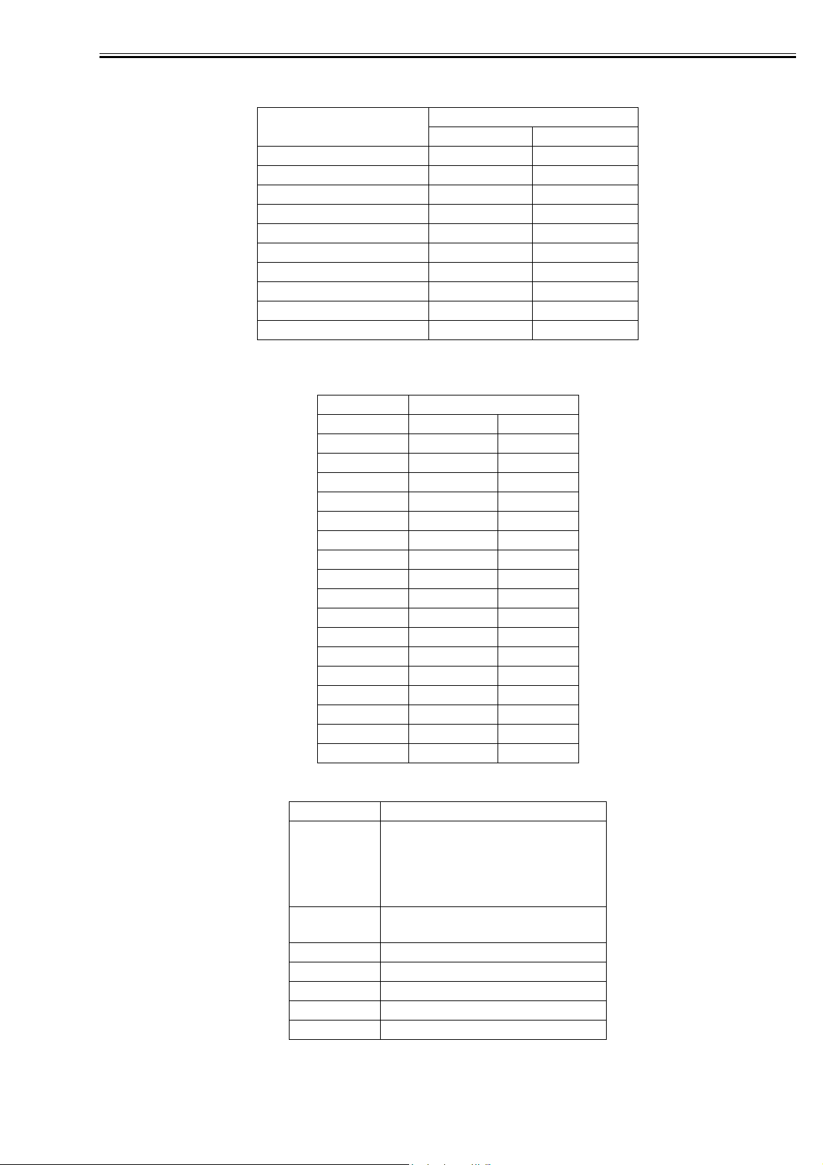
This device provides a FTP server for receiving print data. The device can accept print jobs sent in FTP
from client PCs. This is called FTP printing, a new feature first employed on iRC 6800. To use this feature, the FTP Print option must be selected. It is selected by default. You can access the option by pressing
Ad Func, System Settings, Network Settings, TCP/IP Settings, and FTP Print Settings buttons. In FTP
Print Settings screen, only one pair of a user name and password can be entered for the user who can log
in to the FTP server. No settings are made for both of the fields by default.
F-2-1
Commands
The FTP server complies with the RFC 959 -- File Transfer Protocol -- but provides only printing function.
Thus the server does not support other functions required as a RFC 959 compliant server. The commands
available for the FTP client are "user," "password," "bin," "put," "bye," "hash," and "help." There is no
use of other commands since the server does not provide functions other than printing. The following lists
the notes to use the commands.
- To send print data with the command "put," set the mode to the binary mode using the command "bin."
In the ascii mode, the data cannot be sent with the command "put."
- If the user and password fields are blank, any user with any password can log in. If the user name "anonymous" is used, any character string can be entered as the password. The device displays the string in User
filed of Log screen.
2-2

Chapter 2
- This function is featured mainly to print prn files output from PDL drivers. The device processes text
files and the like as it receives data in LPR (and does not properly print depending on settings.) The device
of PostScript-compatible model can print PDF files, compatible with PDF V1.3.
The following shows a command specification example, which you will connect the device of the IP address "172.16.181.131" in FTP with the user name "test" and the password "test" and print the file
"test.prn" in the root directory of the drive C on the client PC.
C:\>ftp 172.16.181.131
Connected to 172.16.181.131.
220 Connection established.
User (172.16.181.131:(none)): test
331 Password required to login.
Password: Note: The password is not displayed.
230 User test logged in.
ftp> bin
200 Type set to IMAGE (binary).
ftp> put c:\test.prn
200 PORT command successful.
150 Opened BINARY data connection for file transfe
226 Transfer complete.
ftp: 15871 bytes sent in 0.00Seconds 15871000.00Kb
ftp> bye
221 Server closing down connection.
C:\>
Number of Connections and Used Ports
The maximum number of concurrent connections is three. If a user attempts to connect to the FTP server
with which three connections have been established, the user cannot log in and fails in connection. The
default port for the FTP server is 21. There is no measure provided to change the port.
The control port time-out is set to 300 seconds. You need to re-connect to the server if you have left the
connection for 300 seconds or more after logging in. The data port time-out is 60 minutes. If a data transmission takes more than 60 minutes, the connection is automatically disconnected.
2-3
Chapter 2
2.1.3 Halftone Settings
Halftone Settings (PS B&W printers)
F-2-2
0011-3458
F-2-3
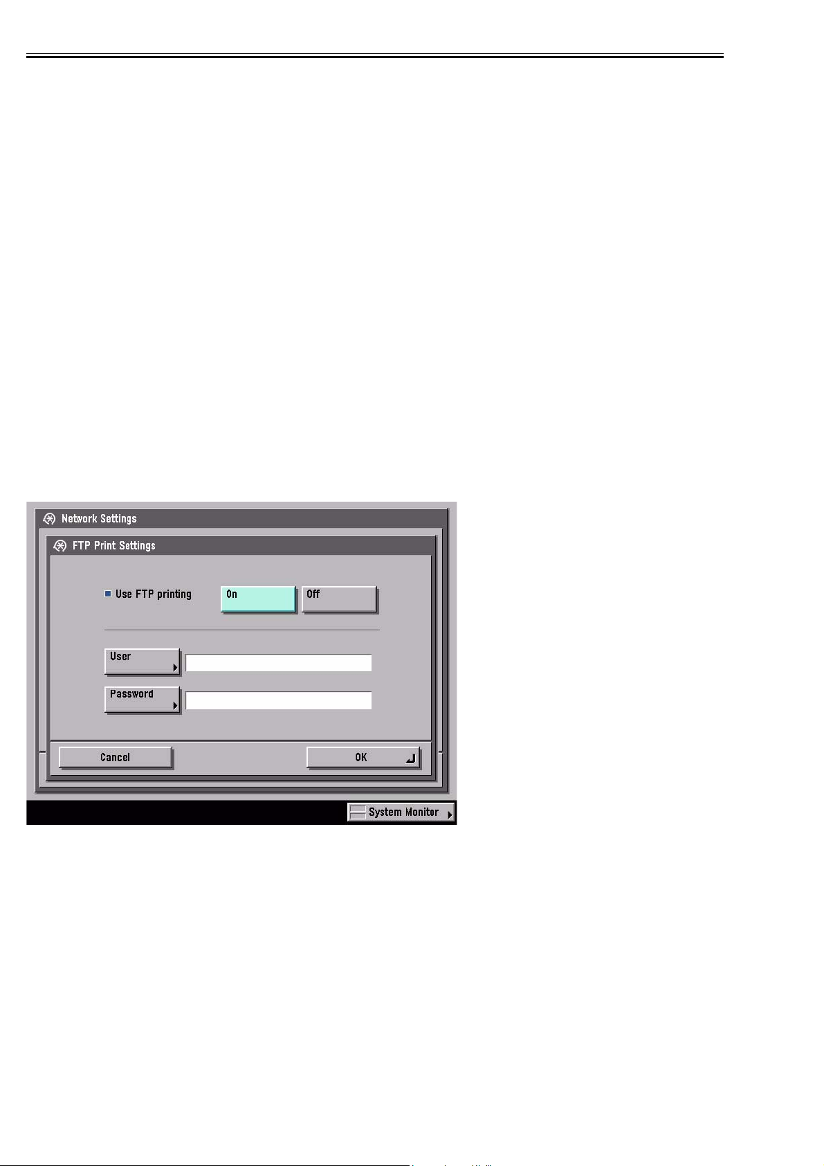
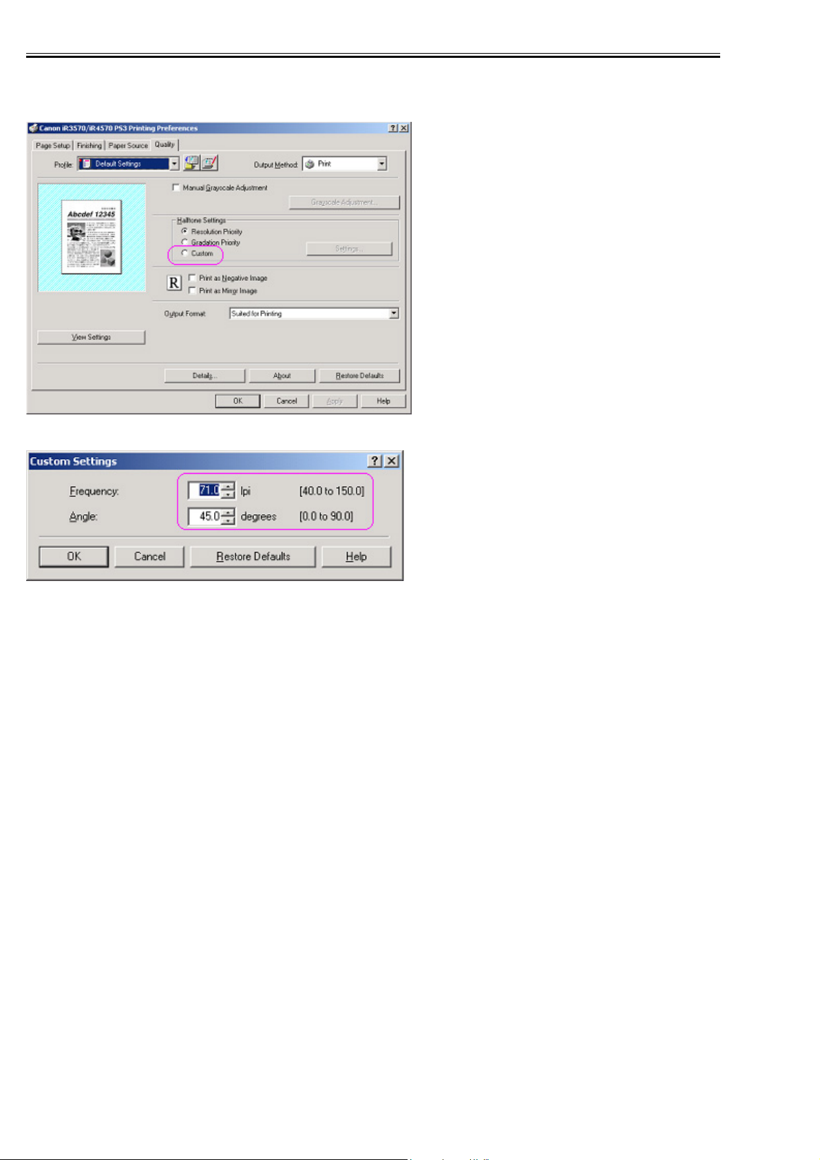
Only for monochrome PS printers, it will be possible to specify the halftone screen frequency and angle.
For that, in the "Halftone Settings" section in the "Quality" tab, the "Custom" radio button and the "Settings" buttonwill be provided.
The "Settings" button will be disabled by default and will be enabled by selecting the "Custom" radio button.
Clicking the "Settings" button will open the "Custom Settings" dialog to set the halftone screen frequency
and angle.
The "Frequency" spin box will default to a value of 71.0 and will accept a value between 40.0 and 150.0.
The "Angle" spin box will default to a value of 45.0 and will accept a value between 0.0 and 90.0.
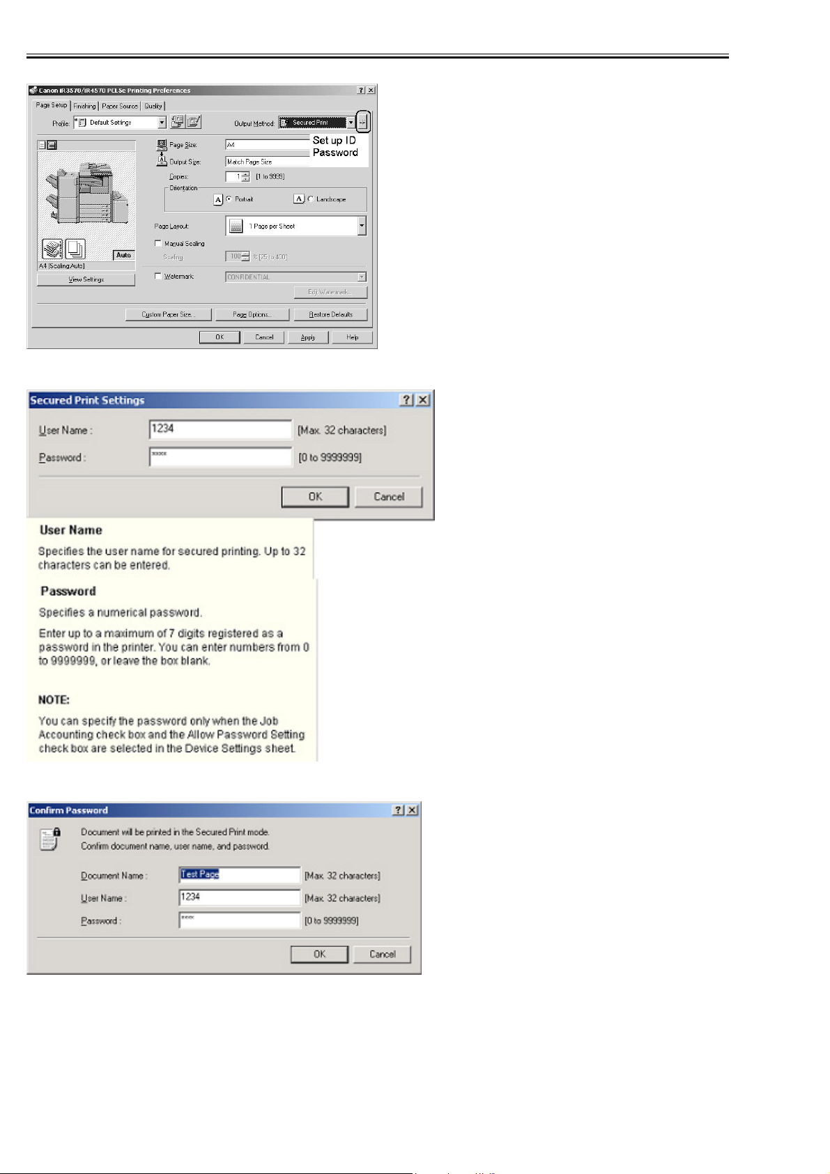
2.1.4 Secured Print Jobs
0011-3459
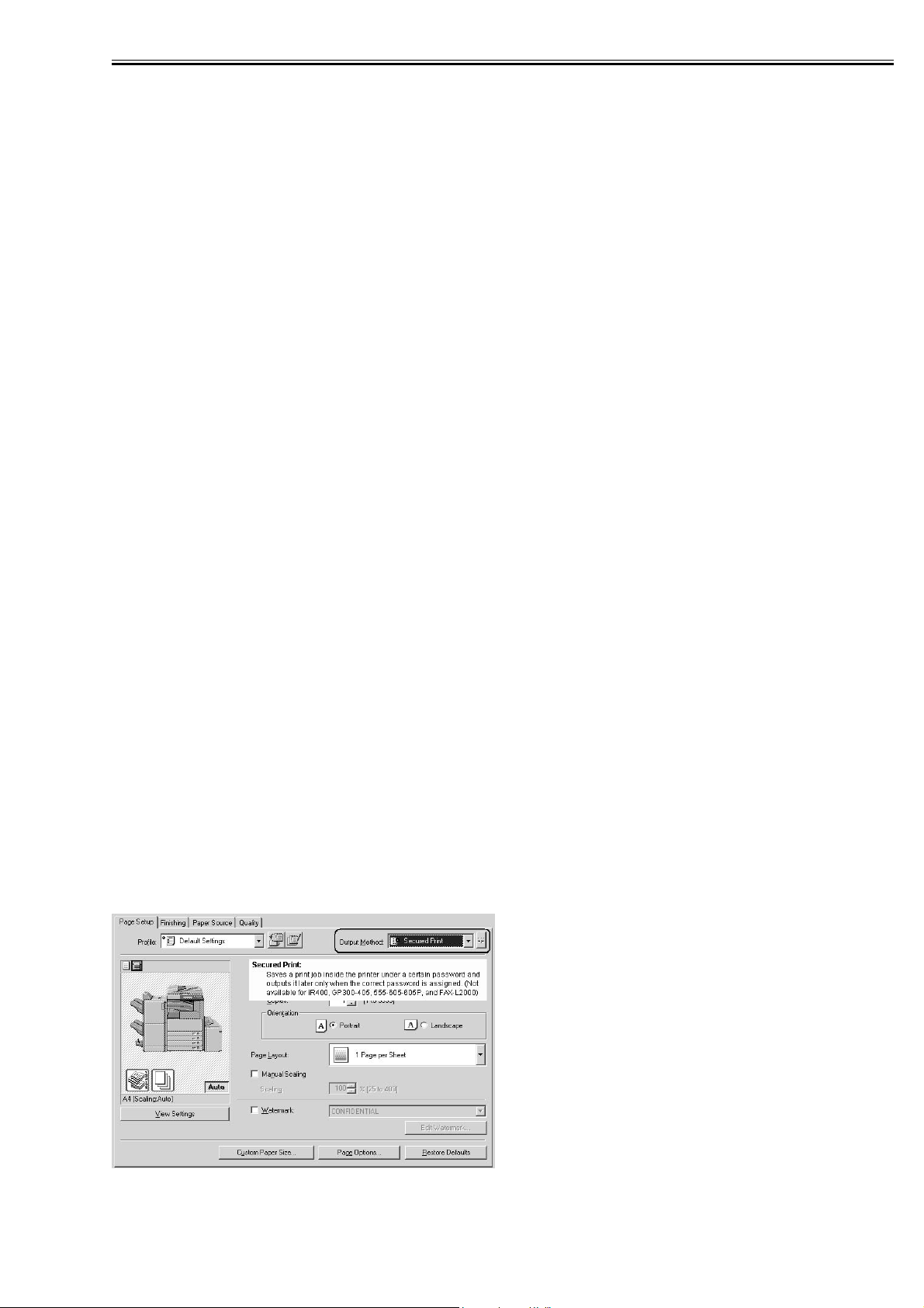
Overview:
Secured Print is the function that a password is provided to the PDL(UFR II and PCL) print job and it is
sent to the device. Then, it is rasterized on the device side, saved in the image server and output by entering
the password from the device's panel. This function is used when dealing with the documents which you
do not want other people to see, such as confidential documents.
a) Password is provided.
In order to conduct the Secured Print, the printer driver requires the user to enter the password from GUI.
This password is provided to the print job and it is sent to the device. This function can be conducted by
using CPCA protocol(UFR II and PCL).
b) Job execution and pending
PDL print job sent to the device as the Secured Print job is compiled on the job queue like the normal PDL
print job. Then, it is rasterized by PDL interpreter, saved in the image server as the document image file
and becomes pending here. However, all job information, such as paper supply/output, the number of copies and finishing information remains.
2-4
Chapter 2
c) Job started by entering the password
If the Secured Print job is pending, the display indicating the pending state appears on the job status screen
of the panel. If you select this job from the panel, you are required to enter the password. When the password you entered is same as the password provided from the printer driver, the pending job will be started.
When the password is different, the job is treated as an error, so it is not started and it remains in the pending state. Entering the password to start the job cannot be executed before the Secured Print job transfers
to the pending state.
d) Output
The started Secured Print job is output to the printer engine with the top priority. This top priority means
that if the jobs can be changed in priority order, the Secured Print job can be prioritized. This job is proceeded according to all job information specified by the printer driver, etc., such as paper supply/output,
the number of copies and finishing information. When the processing is completed and all documents are
output, the documents and job information stored in the image server are deleted.
e) Operations for Secured Print jobs
Like other print jobs, Secured Print jobs can be deleted, interrupted, restarted and promoted by operating
from the status screen of the print job. Regarding these operations, the device side does not distinguish
from operations of the normal PDL job. That is, the password entry is required only when the job is output.
If you interrupt or restart the job during outputting, the password setting and matching are not conducted.
f) Automatically delete of Secured Print Jobs
When Secured Print Job is continuing being suspended for a long time, apparatus deletes a job automatically.
There are options for automatic job deletion time -- 1, 2, 3, 6, 12, and 24 hours. With a view of security
and memory usage, no option longer than 1 day is available. The elapsed time starts after all the processes
for the PDL data and the rendering for all the image data, for which Secured Print is specified, are finished.
g) Specifications and Limitations on Secured Print Jobs
The limitations on Secured Print jobs are listed as follows.
- Once data of a Secured Print job is printed, it is immediately deleted and cannot be printed any more.
- If the power for the controller is shut down, unprinted data of a Secured Print job is deleted from the printer.
- All the job information, represented by the paper source and output information, information of the
number of copies, and finishing information, cannot be changed on the printer.
- If the entire raster information for a Secured Print job cannot be stored in the image server (hard disk
drive) due to insufficient memory, the job results in an error, to be deleted.
- Up to 50 Secured Print jobs of image data being rendered and left unprinted can be stored.
F-2-4
2-5
Chapter 2
F-2-5
F-2-6
F-2-7
2-6
Chapter 2
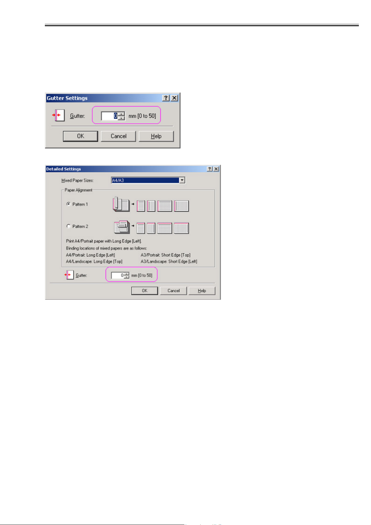
2.1.5 Up to 50 mm of Gutter
0011-3460
Up to 50 mm of the gutter can be specified. The gutter can be adjusted within a range from 0 mm to 50
mm in 1 mm increments. The local UI and the print driver have the controls for the gutter settings.
The image is shifted to the width value specified for gutter, making a margin. If the shift causes the image
to overflow from the printable area, the overflowing area is missing from the print results. The overflowing image will not be reduced to fit into the printable area.
F-2-8
F-2-9
The gutter width range changed to 0-50 mm.
US: 0.0 to 2.0 inches
UK: 0.0 to 50.0 mm
2.1.6 Processing on System
0011-3461
Processing after Power Shutdown
If the power is shut down during PDL data processing, all the image data temporarily stored in the hard
disk drive to be printed or stored in Mail Boxes are destroyed and the jobs are canceled. PDL data stored
in the hard disk drive immediately before a power shutdown are destroyed as the power is shut down.
Processing the data of those, therefore, will not resume when the power is turned on after the shutdown.
Jobs interrupted by a power shutdown will be displayed in the Log list with the End Code "NG (#852)."
2-7
Chapter 2
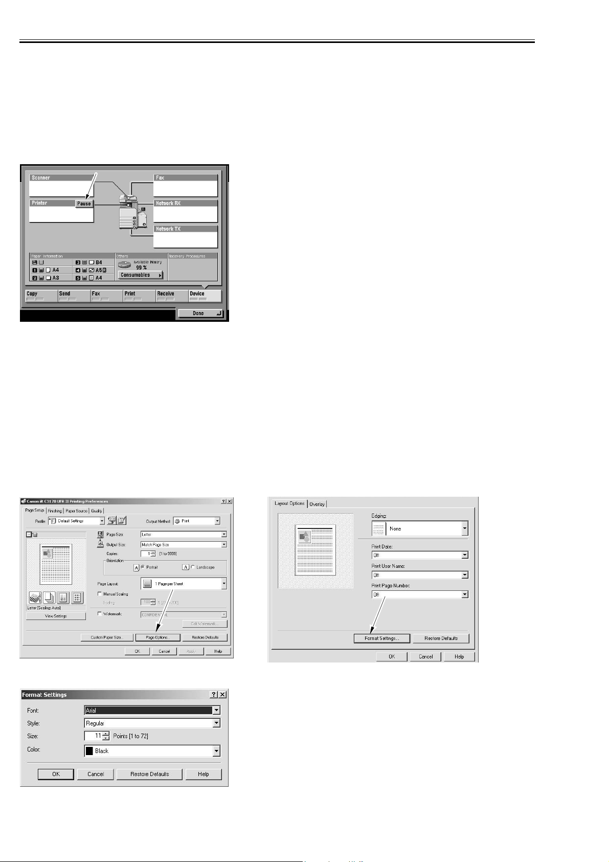
2.1.7 Print Pause
0011-3462
You can suspend ongoing printing of all jobs from the control panel. Likewise, you can resume the printing
working from the control panel. There will be no suspension of data input for the network or PDL processing. To enable Print Pause, use the following service mode:
COPIER>OPTION>USER>PR-PSESW
0: disable (do not indicate)
1: enable (indicate)
(default: '0')
F-2-10
2.1.8 Format Settings
0011-3464
A function to enable the selection of the following will be added in regard to the text used to print the result
of a job and the following notations to the lead or trail edge: Print Date, Print User Name, Print Page
Number:
Font
Style
Size
Color
A change made to Format Settings will affect the following in common, and individual selection will not
be possible: Print Date, Print User Name, Print Page Number.
F-2-11
F-2-12
2-8
Chapter 2
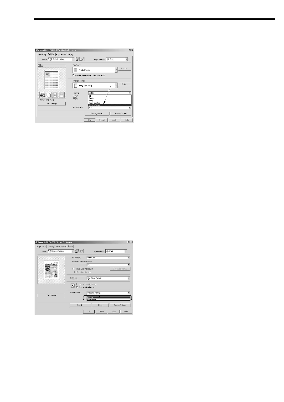
2.1.9 Staple & Group
0011-3465
You can use it to enable the selection of stapling when printing in Group mode. Staple & Group permits
stapling of pages in sets.
F-2-13
If 'Store' is selected as 'Output Method' on the Finishing tab, [Staple & Group] will be grayed out, not permitting selection.
If 'Store' is selected as 'Output Method' while selecting [Staple & Group], a switchover will take place for
[Finishing] so that [Staple & Group] will be [Collate].
2.1.10 PS_EPS file Output
0011-3466
PS Printer Driver Only
Support of EPS (Encapsulated PostScript)
When printing an EPS file existing in an application program, selection of PS_EPS File Output will enable
printing of the EPS data as it is without conversion into PS print data.
In EPS, page size is not described in the file so that the page range is determined with reference to the image size.
The paper size will be fixed to the default paper size specified as part of print settings on the iR engine
control panel.
_If the image is smaller than the paper size, centering will take place.
_If the image is larger than the paper size, on the other hand, the upper left corner of the paper and that of
the page will be matched.
F-2-14
Reference
EPS data contains PostScript data created using graphics application software (e.g., Adobe Illustrator) and
preview data for display in DTP software being used. When an EPS file is selected as the output mode,
some applications prevent printing of the preview data.
2-9
Chapter 2
2.2 Changed Function
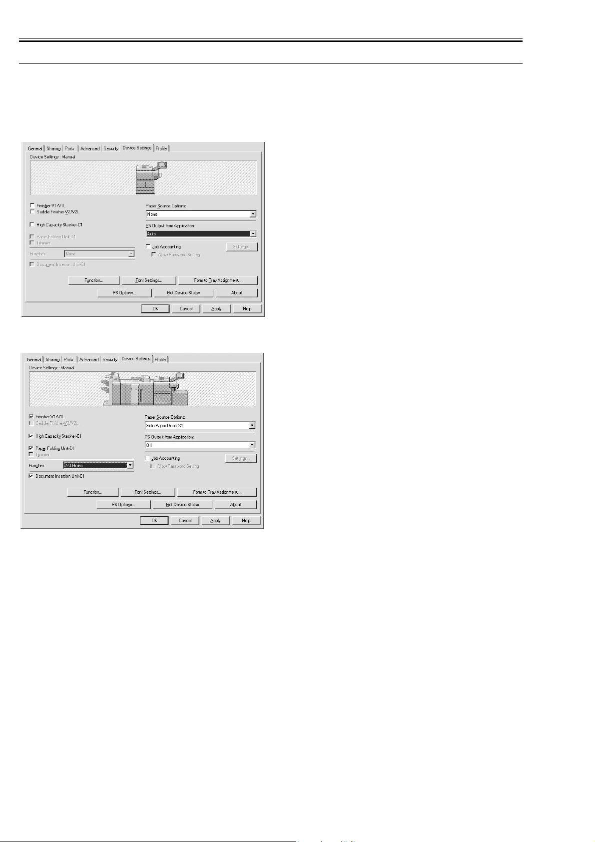
2.2.1 Device Settings
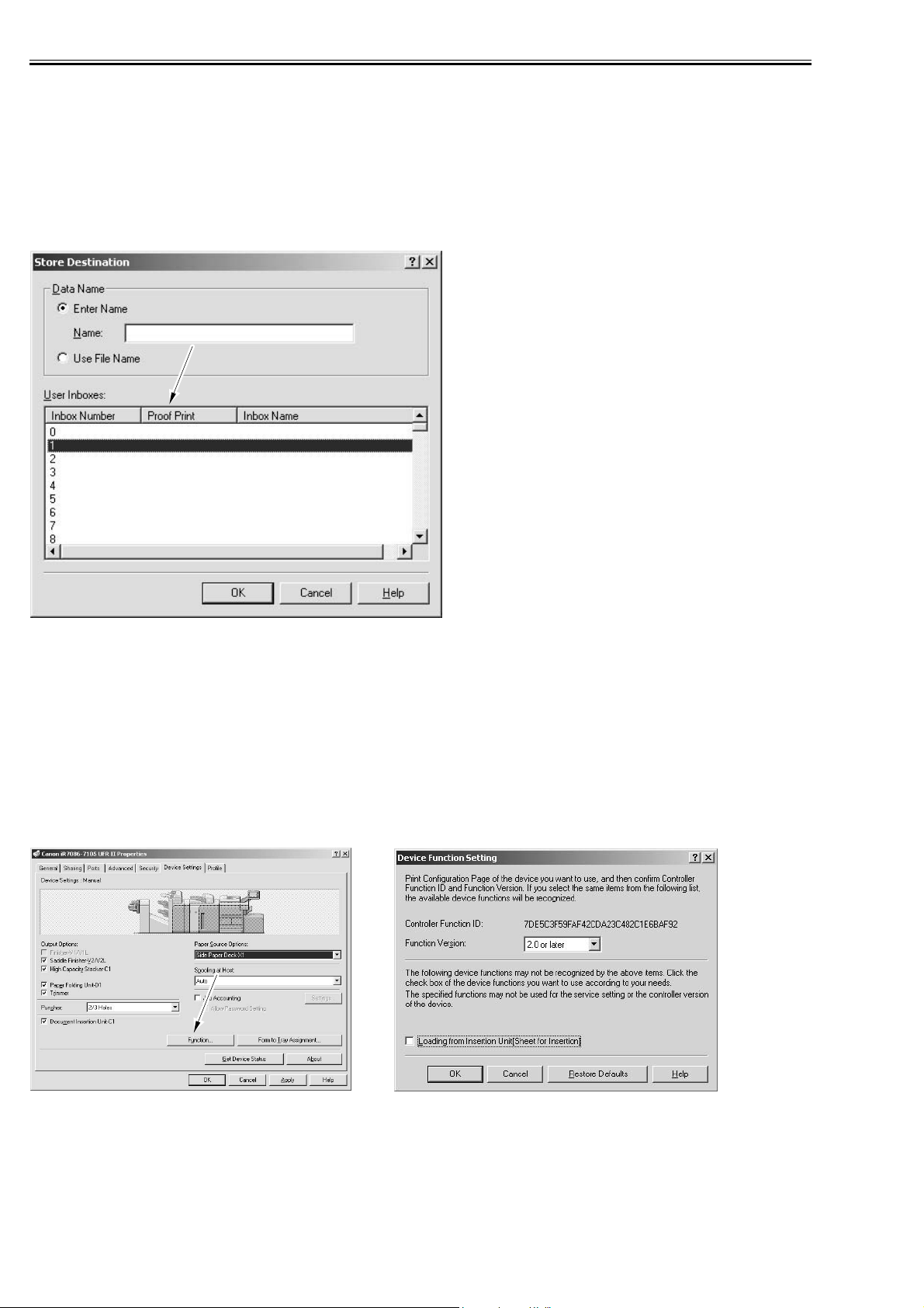
0011-3467
In order to check if each option is set correctly, click a tab of 'Device Settings' on the properties screen of
printer driver.
F-2-15
F-2-16
How to select [Perfect Binder-A1] and [Document Insertion Unit-C1]:
-Deviced Settings>Function>Device Function Settings_Function Version then 2.0 or later.
-Back to Deviced Settings then press Apply.
-Select Perfect Binder-A1 and Document Insertion Unit-C1.
Specification:
- If Finisher-V1/V1L is checked Sddle Finisher-V2/V2L is disabled, and vice versa.
- Pper Folding Unit-D1 and Punch will only be enabled Finisher-V1/V1L or Saddle Finisher-V2/V2L is
checked
- Trimmer will only be enabled if Saddle Finisher-V2/V2L is checked.
- Punch will only be enabled Finisher-V1/V3 or Saddle Finisher-V2/V2L is checked.
- If(Saddle)FinisherV1/V2/V1L/V2L is cheked, Document Insertion Units-C1 is enabled but uncheked.
- If Perfect Binder-A1 is checked, Document Insertion Units-C1 is enabled but uncheked.
2-10
Chapter 2
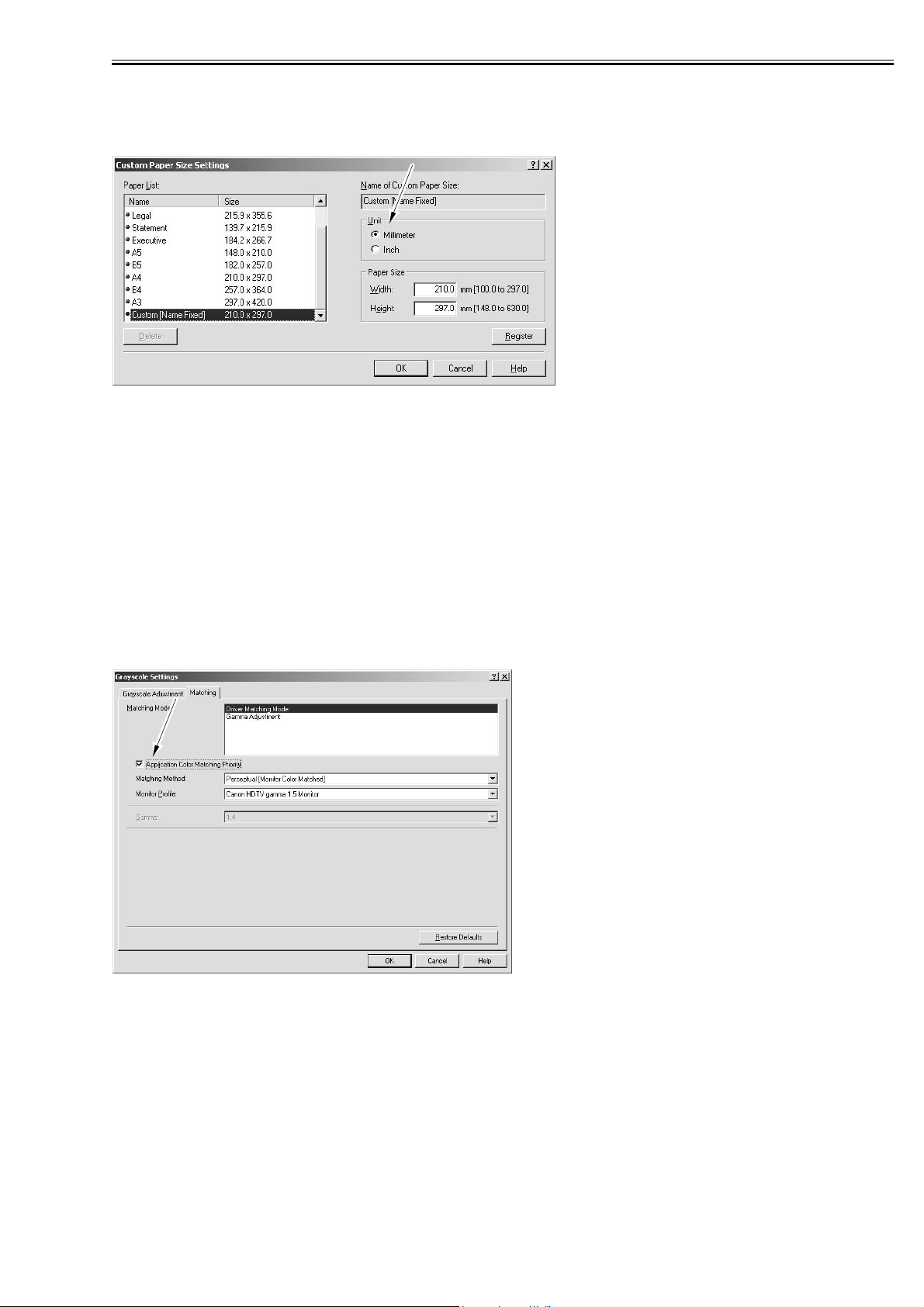
2.2.2 Custom Paper Size Settings Unit(Millimeter-Inch)
0011-3468
In the past, paper size was displayed in millimeter or inch depending on the destinations concerning the
custom paper size settings. This printer driver enables users to select the unit (Millimeter or Inch).
F-2-17
2.2.3 Application Color Matching Priority
0011-3469
There have been some cases that color reproducibility may become inappropriate if users perform color
matching in the printer driver again though they have already done it in PC.
When the checkbox for Application Color Matching Priority under [ In Quality > Manual Grayscale Settings > Grayscale Settings > Matching] is cleared, it can declare to the application software on PC that
Driver handles ICM processing.
This notice enables to perform Image Color Matching processing as designated in printer driver UI since
the process is not done to the color values given from OS to driver.
Though Application Color Matching Priority is set to on as default so that existing version can be compatible, when specified color tinge cannot be materialized, clearing the checkbox makes it manageable.
Applicable OS: Windows2000, Windows XP, Windows 2003 Server
F-2-18
2-11
Chapter 2
2.2.4 Objective(PCL): Halftones(PS):
- Default Setting(PS): Printer Default(Uses the Setting from the printer.
- Default Setting(PCL): Pattern2
- For PCL, Each Objective mode has a default Halftone setting:
PCL:
T-2-1
Objective Default Halftone
Text Patterm2
Publications Patterm1
Graphics Patterm2
Photos Patterm5
Designs(CAD) Patterm4
-There are the values of image, Graphics and Text for every Pattern.
T-2-2
PS PCL
Halftone IMG GRA TXT IMG GRA TXT
Resolution RRR- - Gradation G G G - - High Resolution H H H - - Pattern1 R H H T G H
Pattern2 GHHTTR
Pattern3 RRHGGG
Pattern4 GGHGHH
Pattern5 GRHTTT
Pattern6 GGR--Pattern7 GRH---
T : Color Tone
G : Gradation
R : Resolution
H : High Resolution
Halftones:
Specifies the method for halftone processing.
0011-3470
Printer Default:
Uses the setting from the printer.
Resolution:
Provides halftone processing giving priority to resolution. This method is suitable to output a document
containig mostly texgt and line drawings.
Grfadation:
Probides halftone processing giving priority to gradation. This method is suitable to output a document
countaing many images.
2-12
2.3 New Function
Chapter 2
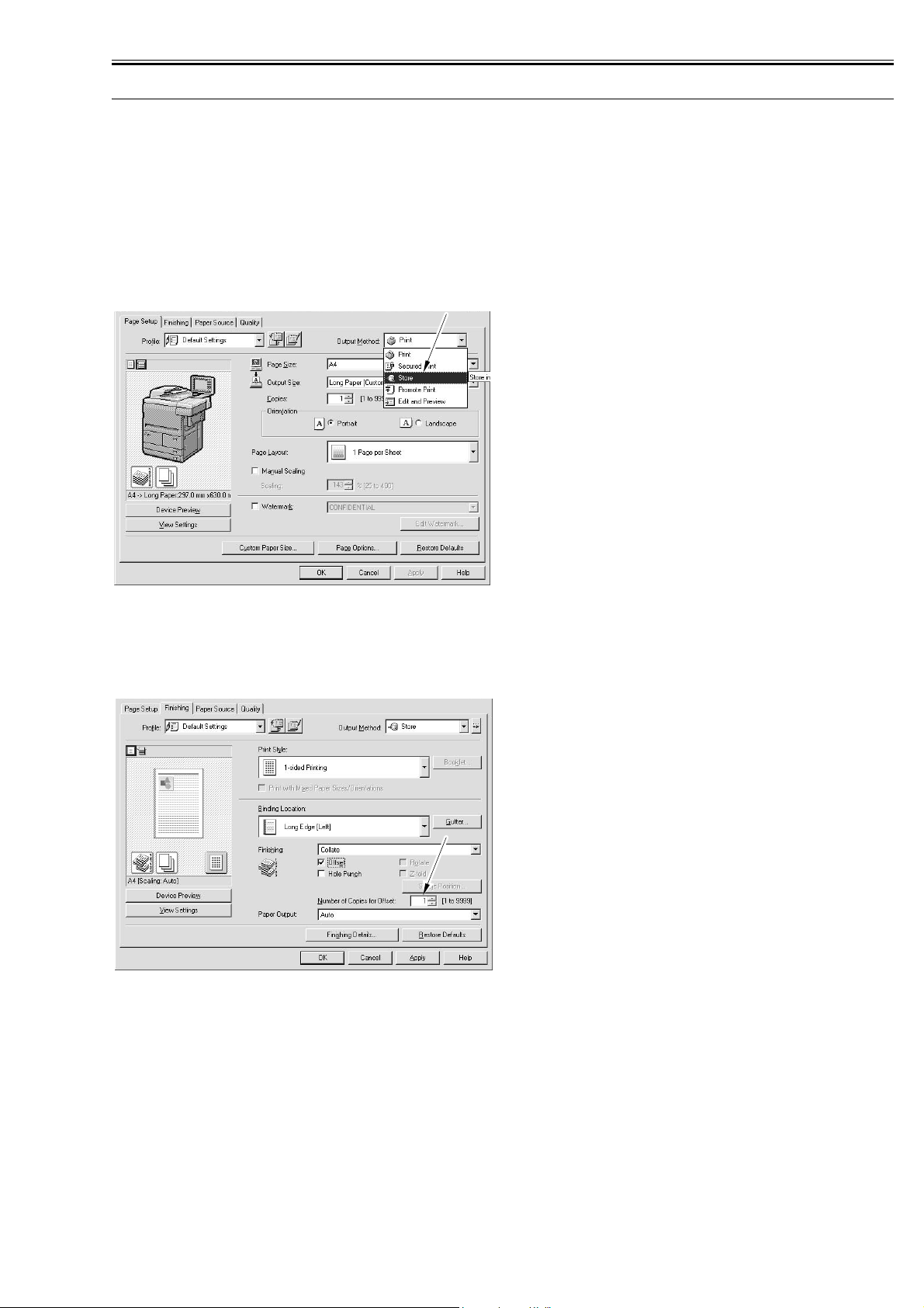
2.3.1 Custom Paper Size Settings(Long Paper)
0011-3471
Long Paper is available as Custom Paper Size.
Long Paper size can be input as a panel setting value.
The restrictions on Long Paper are described below.
-In Long Paper, 1200 dpi resolution is not available. When Long Paper is selected, 1200 dpi resolution is
not selectable. If 1200 dpi resolution is specified at the start of job, it is processed with 600 dpi.
-Long Paper job cannot be stored in inbox. When Long Paper is selected, [Store] is not selectable in [Output Method]. If users select [Store], it is automatically changed to [Print].
F-2-19
2.3.2 Finishing(Number of Copies for Offset)
0011-3472
Finishing is done by designated number of copies for offset. The number can be specified from 1 to 9999.
F-2-20
2-13
Chapter 2
2.3.3 Proof Print
0011-3473
When registering data in inbox, print a copy at the same time.
How to set Proof Print:
1. Specify the inbox number to execute 'Proof Print' on the control panel of the iR main body.
2. Execute 'Get Device Status' in the driver and write the data in UI.
3. When specifying the inbox number designated to execute 'Proof Print' and then printing, Proof Print is
done.
F-2-21
2.3.4 Perfect Binding
0011-3475
Perfect Binding requires Perfect Binder-A1.
Perfect Binding is a function that pastes the binding margins of pages of multi-page document, puts the
cover on them, and executes a booklet printing process.
You need set up "2.0 or later" on Printer Properties.
Printer Properties > Device Settings > Function
Device Function Setting > Function Version > 2.0 or later
F-2-22
Following printing methods are selectable in the printer driver.
- Addition of [Perfect Binding] to [Print Style]
[Perfect Binding] is added besides the existing [Booklet Printing].
When selecting [Perfect Binding], [Perfect Bound Cover Settings], which is used for detailed settings, appears as shown above.
- Addition of [Perfect Bound Cover Settings]
2-14
 Loading...