

Canon iR1200 Series, iR1570F Service Manual

Jun 17 2004
Service Manual
iR1200 Series
iR1570F


Application
This manual has been issued by Canon Inc. for qualified persons to learn technical theory, installation, maintenance, and
repair of products. This manual covers all localities where the products are sold. For this reason, there may be
information in this manual that does not apply to your locality.
Corrections
This manual may contain technical inaccuracies or typographical errors due to improvements or changes in products.
When changes occur in applicable products or in the contents of this manual, Canon will release technical information
as the need arises. In the event of major changes in the contents of this manual over a long or short period, Canon will
issue a new edition of this manual.
The following paragraph does not apply to any countries where such provisions are inconsistent with local law.
Trademarks
The product names and company names used in this manual are the registered trademarks of the individual companies.
Copyright
This manual is copyrighted with all rights reserved. Under the copyright laws, this manual may not be copied,
reproduced or translated into another language, in whole or in part, without the written consent of Canon Inc.
COPYRIGHT © 2001 CANON INC.
Printed in Japan
Caution
Use of this manual should be strictly supervised to avoid disclosure of confidential information.
Introduction
Symbols Used
This documentation uses the following symbols to indicate special information:
Symbol Description
Indicates an item of a non-specific nature, possibly classified as Note, Caution, or Warning.
Indicates an item requiring care to avoid electric shocks.
Indicates an item requiring care to avoid combustion (fire).
Indicates an item prohibiting disassembly to avoid electric shocks or problems.
Indicates an item requiring disconnection of the power plug from the electric outlet.
Indicates an item intended to provide notes assisting the understanding of the topic in question.
Indicates an item of reference assisting the understanding of the topic in question.
Provides a description of a service mode.
Provides a description of the nature of an error indication.
Memo
REF.

Introduction
The following rules apply throughout this Service Manual:
1. Each chapter contains sections explaining the purpose of specific functions and the relationship between electrical
and mechanical systems with reference to the timing of operation.
In the diagrams, represents the path of mechanical drive; where a signal name accompanies the symbol ,
the arrow indicates the direction of the electric signal.
The expression "turn on the power" means flipping on the power switch, closing the front door, and closing the
delivery unit door, which results in supplying the machine with power.
2. In the digital circuits, '1'is used to indicate that the voltage level of a given signal is "High", while '0' is used to
indicate "Low".(The voltage value, however, differs from circuit to circuit.) In addition, the asterisk (*) as in
"DRMD*" indicates that the DRMD signal goes on when '0'.
In practically all cases, the internal mechanisms of a microprocessor cannot be checked in the field. Therefore, the
operations of the microprocessors used in the machines are not discussed: they are explained in terms of from
sensors to the input of the DC controller PCB and from the output of the DC controller PCB to the loads.
The descriptions in this Service Manual are subject to change without notice for product improvement or other
purposes, and major changes will be communicated in the form of Service Information bulletins.
All service persons are expected to have a good understanding of the contents of this Service Manual and all relevant
Service Information bulletins and be able to identify and isolate faults in the machine."


Contents
Contents
Chapter 1 Introduction
1.1 Product Specifications....................................................................................................................................... 1- 1
1.1.1 Names of Parts ............................................................................................................................................ 1- 1
1.1.2 Using the Machine ...................................................................................................................................... 1- 6
1.1.3 User Mode Items....................................................................................................................................... 1- 11
1.1.4 Maintenance by the User........................................................................................................................... 1- 38
1.1.5 Safety ........................................................................................................................................................ 1- 42
1.1.6 Product Specifications .............................................................................................................................. 1- 45
1.1.7 Function List ............................................................................................................................................. 1- 51
Chapter 2 Installation
2.1 Making Pre-Checks ........................................................................................................................................... 2- 1
2.1.1Selecting the Site ......................................................................................................................................... 2- 1
2.2 Unpacking and Installation................................................................................................................................ 2- 2
2.2.1Before Starting ............................................................................................................................................ 2- 2
2.2.2Installation Procedure.................................................................................................................................. 2- 2
2.2.3Unpacking ................................................................................................................................................... 2- 2
2.2.4Fitting the Cartridge .................................................................................................................................... 2- 3
2.2.5Fitting the Toner bottle................................................................................................................................ 2- 3
2.2.6Putting Paper in the Cassette ....................................................................................................................... 2- 4
2.2.7Putting Paper in the Manual Feed Tray....................................................................................................... 2- 5
2.2.8Connecting the Interface Cable ................................................................................................................... 2- 5
2.2.9Connect the power cord...............................................................................................................................2- 6
2.2.10Fitting the Delivery Tray........................................................................................................................... 2- 6
2.2.11Setting the Printer Functions ..................................................................................................................... 2- 6
2.3 Connection to Telephone Line .......................................................................................................................... 2- 7
2.3.1Connecting the Modular Cable (if equipped with fax functions)................................................................ 2- 7
2.3.2Setting the Date/Time (user mode) ............................................................................................................. 2- 7
2.3.3Setting the Dial Type................................................................................................................................... 2- 7
2.3.4Executing Communications Testing ........................................................................................................... 2- 7
2.4 Checking the Images/Operations....................................................................................................................... 2- 9
2.4.1Checking the Copy Images.......................................................................................................................... 2- 9
2.5 Relocating the Machine................................................................................................................................... 2- 10
2.5.1When Relocating the Machine .................................................................................................................. 2- 10
Chapter 3 Basic Operation
3.1 Construction ......................................................................................................................................................3- 1
3.1.1Functional Construction .............................................................................................................................. 3- 1
3.1.2Functional Block Diagram .......................................................................................................................... 3- 2
3.1.3Image Processor PCB.................................................................................................................................. 3- 2
3.1.4DC Controller PCB ..................................................................................................................................... 3- 3

Contents
3.1.5Control Panel PCB.......................................................................................................................................3- 5
3.1.6Power Supply PCB ......................................................................................................................................3- 5
3.1.7Analog Processor PCB ................................................................................................................................3- 5
3.1.8Sensor PCB..................................................................................................................................................3- 5
3.1.9Laser Driver/BD PCB..................................................................................................................................3- 5
3.1.10Main Motor/Scanner Motor Driver ...........................................................................................................3- 5
3.1.11Printer Controller PCB ..............................................................................................................................3- 5
3.1.12NCU PCB (if equipped with fax functions) ..............................................................................................3- 6
3.1.13Modular Jack PCB (if equipped with fax functions).................................................................................3- 6
3.1.14Sensor Relay PCB......................................................................................................................................3- 6
3.1.15Controlling the Main Motor.......................................................................................................................3- 7
3.1.16Reproduction Processes.............................................................................................................................3- 7
3.2 Basic Sequence ................................................................................................................................................3- 11
3.2.1Basic Sequence of Operations at Power-On..............................................................................................3- 11
Chapter 4 Original Exposure System
4.1 Construction.......................................................................................................................................................4- 1
4.1.1Major Components ......................................................................................................................................4- 1
4.2 Parts Replacement Procedure ............................................................................................................................4- 2
4.2.1 Reader Unit .................................................................................................................................................4- 2
4.2.2 Copyboard glass ..........................................................................................................................................4- 5
4.2.3 Sensor PCB .................................................................................................................................................4- 5
4.2.4 Scanner Motor .............................................................................................................................................4- 7
4.2.5 Contact sensor .............................................................................................................................................4- 8
Chapter 5 Laser Exposure
5.1 Construction.......................................................................................................................................................5- 1
5.1.1Outline .........................................................................................................................................................5- 1
5.2 Parts Replacement Procedure ............................................................................................................................5- 2
5.2.1 Laser Scanner Unit ......................................................................................................................................5- 2
Chapter 6 Image Formation
6.1 Construction.......................................................................................................................................................6- 1
6.1.1Outline .........................................................................................................................................................6- 1
6.2 Parts Replacement Procedure ............................................................................................................................6- 2
6.2.1 Developing Cylinder ...................................................................................................................................6- 2
6.2.2 Developing Blade........................................................................................................................................6- 3
6.2.3 Transfer Charging Roller ............................................................................................................................6- 5
6.2.4 Toner Bottle Sensor.....................................................................................................................................6- 6
6.2.5 Waste Toner Full Sensor .............................................................................................................................6- 8
Chapter 7 Pickup/Feeding System
7.1 Construction.......................................................................................................................................................7- 1
7.1.1Outline .........................................................................................................................................................7- 1
7.2 Detecting Jams...................................................................................................................................................7- 3

Contents
7.2.1 Jam Detection Outline................................................................................................................................. 7- 3
7.2.2 Delivery Jams.............................................................................................................................................. 7- 3
7.2.3 Stationary Jams ...........................................................................................................................................7- 3
7.2.4 Other Jams .................................................................................................................................................. 7- 4
7.3 Cassette Pick-Up Unit ....................................................................................................................................... 7- 5
7.3.1Outline ......................................................................................................................................................... 7- 5
7.3.2Retry Pickup ................................................................................................................................................ 7- 5
7.3.3Detecting the Size of Paper ......................................................................................................................... 7- 6
7.4 Manual Feed Pickup Unit.................................................................................................................................. 7- 7
7.4.1Outline ......................................................................................................................................................... 7- 7
7.4.2Retry Pickup ................................................................................................................................................ 7- 7
7.4.3Detecting the Size of Paper ......................................................................................................................... 7- 8
7.5 Delivery ............................................................................................................................................................. 7- 9
7.5.1Outline ......................................................................................................................................................... 7- 9
7.5.2Auto Delivery Control................................................................................................................................. 7- 9
7.5.3Reducing the Copying Speed .................................................................................................................... 7- 10
7.6 Parts Replacement Procedure.......................................................................................................................... 7- 11
7.6.1 Pickup Roller ............................................................................................................................................ 7- 11
7.6.2 Separation Pad .......................................................................................................................................... 7- 12
7.6.3 Cassette Pickup Solenoid.......................................................................................................................... 7- 12
7.6.4 Manual Feed (Upper)................................................................................................................................ 7- 14
7.6.5 Manual Feed (Lower)................................................................................................................................ 7- 15
7.6.6 Manual Pickup Roller ............................................................................................................................... 7- 15
7.6.7 Manual Feed Tray sensor.......................................................................................................................... 7- 16
7.6.8 Manual Feed Pickup Solenoid .................................................................................................................. 7- 21
7.6.9 Registration Roller Unit............................................................................................................................ 7- 27
7.6.10 Vertical Path Roller................................................................................................................................. 7- 28
Chapter 8 Fixing System
8.1 Construction ......................................................................................................................................................8- 1
8.1.1Outline ......................................................................................................................................................... 8- 1
8.2 Various Control Mechanisms............................................................................................................................ 8- 2
8.2.1 Controlling the Fixing Roller Temperature ................................................................................................ 8- 2
8.2.2 Controlling the Fixing File Bias Temperature ............................................................................................ 8- 3
8.3 Protective Functions .......................................................................................................................................... 8- 4
8.3.1Outline ......................................................................................................................................................... 8- 4
8.3.2Detecting a Fault in the Fixing Assembly ................................................................................................... 8- 4
8.4 Parts Replacement Procedure............................................................................................................................ 8- 6
8.4.1 Fixing Unit .................................................................................................................................................. 8- 6
8.4.2 Pressure Roller ............................................................................................................................................ 8- 8
8.4.3 Fixing Film................................................................................................................................................ 8- 12
8.4.4 Fixing Delivery Sensor ............................................................................................................................. 8- 15
Chapter 9 External and Controls
9.1 Fans ...................................................................................................................................................................9- 1
9.1.1Outline ......................................................................................................................................................... 9- 1
9.2 Power Supply System........................................................................................................................................ 9- 2

Contents
9.2.1 Power Supply ..............................................................................................................................................9- 2
9.2.2 Protection Function .....................................................................................................................................9- 4
9.2.3 Backup Battery............................................................................................................................................9- 4
9.2.4 Energy-Saving Function..............................................................................................................................9- 8
9.3 Parts Replacement Procedure ..........................................................................................................................9- 10
9.3.1 Control Panel.............................................................................................................................................9- 10
9.3.2 Analog Processor PCB ..............................................................................................................................9- 10
9.3.3 Removing the DC Controller PCB............................................................................................................9- 12
9.3.4 Image Processor PCB................................................................................................................................9- 16
9.3.5 Printer Controller PCB ..............................................................................................................................9- 17
9.3.6 NCU PCB...............................................................................................................................................9- 17
9.3.7 Modular Jack PCB ....................................................................................................................................9- 18
9.3.8 Removing the Printer Power Supply PCB ................................................................................................9- 18
9.3.9 Relay PCB .................................................................................................................................................9- 23
9.3.10 Humidity Sensor......................................................................................................................................9- 25
9.3.11 Reader Unit Slide Detecting Switch........................................................................................................9- 27
9.3.12 Toner Supply Cover Switch ....................................................................................................................9- 30
9.3.13 Fans .........................................................................................................................................................9- 32
9.3.14 Motor of Main Drive Assembly ..............................................................................................................9- 36
9.3.15 Right Door...............................................................................................................................................9- 41
Chapter 10 Original Feeding System
10.1 Basic Construcion..........................................................................................................................................10- 1
10.1.1Outline .....................................................................................................................................................10- 1
10.2 Basic Operation .............................................................................................................................................10- 2
10.2.1Picking Up and Moving Originals ...........................................................................................................10- 2
10.2.2Moving Down the Original Pickup Roller and Moving Up the Original Stopper...................................10- 2
10.3 Detection Jams...............................................................................................................................................10- 4
10.3.1Outline .....................................................................................................................................................10- 4
10.3.2Types of Jams ..........................................................................................................................................10- 4
10.4 Parts Replacement Procedure ........................................................................................................................10- 6
10.4.1 ADF.........................................................................................................................................................10- 6
10.4.2 ADF Drive Unit.......................................................................................................................................10- 7
10.4.3 ADF Motor Unit......................................................................................................................................10- 9
10.4.4 Feeding Outside Guide..........................................................................................................................10- 12
10.4.5 Separation Roller Unit...........................................................................................................................10- 14
10.4.6 Separation Roller ..................................................................................................................................10- 17
10.4.7 Pickup Roller ........................................................................................................................................10- 21
10.4.8 Original Separation Pad ........................................................................................................................10- 24
10.4.9 Registration Roller ...............................................................................................................................10- 25
10.4.10 White Roller .......................................................................................................................................10- 28
10.4.11 Feed Roller .........................................................................................................................................10- 30
10.4.12 Original Feed Roller ...........................................................................................................................10- 32
10.4.13 Original Delivery Roller......................................................................................................................10- 36
10.4.14 Original Sensor....................................................................................................................................10- 39
10.4.15 Registration Sensor .............................................................................................................................10- 42
10.4.16 Original Delivery Sensor.....................................................................................................................10- 44
10.4.17 Slide Guide..........................................................................................................................................10- 47

Contents
10.4.18 Delivery Stacking Tray ....................................................................................................................... 10- 48
Chapter 11 Maintenance and Inspection
11.1 Periodically Replaced Parts........................................................................................................................... 11- 1
11.1.1Periodically Replaced Parts..................................................................................................................... 11- 1
11.2 Durables and Consumables ........................................................................................................................... 11- 2
11.2.1Durables................................................................................................................................................... 11- 2
11.3 Scheduled Servicing Basic Procedure ........................................................................................................... 11- 3
11.3.1Scheduled Servicing Chart ...................................................................................................................... 11- 3
11.4 Cleaning......................................................................................................................................................... 11- 4
11.4.1Outline ..................................................................................................................................................... 11- 4
11.4.2Selfoc Lens Array of the Contact Sensor ................................................................................................ 11- 4
11.4.3Cassette Pickup Roller............................................................................................................................. 11- 5
11.4.4Manual Feed Pickup Roller..................................................................................................................... 11- 5
11.4.5Separation Pad......................................................................................................................................... 11- 5
11.4.6Registration Roller .................................................................................................................................. 11- 5
11.4.7Transfer Guide......................................................................................................................................... 11- 5
11.4.8Transfer Charging Roller......................................................................................................................... 11- 5
11.4.9Separation Static Eliminator.................................................................................................................... 11- 5
11.4.10Paper Path.............................................................................................................................................. 11- 5
11.4.11Fixing Inlet Guide ................................................................................................................................. 11- 5
11.4.12Fixing Pressure Roller ........................................................................................................................... 11- 6
11.4.13Delivery Roller ...................................................................................................................................... 11- 6
11.4.14Back of Copyboard Glass (Back of Shading Plate) .............................................................................. 11- 6
11.4.15Original Pickup Roller (ADF) ............................................................................................................... 11- 6
11.4.16Original Separation Roller (ADF)......................................................................................................... 11- 6
11.4.17Original Separation Pad (ADF)............................................................................................................. 11- 6
11.4.18ADF Registration Roller (ADF)............................................................................................................ 11- 7
11.4.19Original Feed Roller (ADF) .................................................................................................................. 11- 7
11.4.20Original Delivery Roller (ADF) ............................................................................................................ 11- 7
11.4.21Copyboard Glass (Original Reading Area) (ADF)................................................................................ 11- 7
Chapter 12 Standards and Adjustments
12.1 Image Adjustments........................................................................................................................................ 12- 1
12.1.1Leading Edge Read Start Position Adjustment ....................................................................................... 12- 1
12.1.2Left/Right Edge Read Start Position Adjustment.................................................................................... 12- 1
12.2 Scanning System ........................................................................................................................................... 12- 3
12.2.1Preparing a Test Sheet for Adjustment.................................................................................................... 12- 3
12.2.2Contact Sensor LED Intensity Auto Adjustment .................................................................................... 12- 3
12.3 Fixing System................................................................................................................................................ 12- 4
12.3.1Nip Adjustment ....................................................................................................................................... 12- 4
12.4 Electrical Components .................................................................................................................................. 12- 5
12.4.1Outline ..................................................................................................................................................... 12- 5
12.4.2When Replacing the Image Processor PCB ............................................................................................ 12- 5
12.5 ADF ............................................................................................................................................................... 12- 6
12.5.1 Outline..................................................................................................................................................... 12- 6
12.5.2 Adjusting the Mechanical System .......................................................................................................... 12- 6

Contents
12.5.3 Adjusting the Ellectrical System .............................................................................................................12- 7
Chapter 13 Correcting Faulty Images
13.1 Making lnitial Checks....................................................................................................................................13- 1
13.1.1Outline .....................................................................................................................................................13- 1
13.1.2Making Initial Checks..............................................................................................................................13- 1
13.1.3Site Environment .....................................................................................................................................13- 1
13.1.4Checking the Drum Unit..........................................................................................................................13- 1
13.1.5Checking the Paper ..................................................................................................................................13- 1
13.1.6Others.......................................................................................................................................................13- 1
13.1.7Troubleshooting Flow Chart....................................................................................................................13- 2
13.1.8Making Checks in Response to an Image Fault.......................................................................................13- 3
13.1.9Checking the Photointerrupters ...............................................................................................................13- 3
13.2 Outline of Electrical Components .................................................................................................................13- 6
13.2.1 Clutch/Solenoid.......................................................................................................................................13- 6
13.2.2 Sensor ......................................................................................................................................................13- 7
13.2.3 Lamps, Heaters, and Others ....................................................................................................................13- 9
13.2.4 PCBs......................................................................................................................................................13- 10
13.2.5 Variable Resistors(VR), Light-Emitting Diodes(LED),and Check Pins by PCB .................................13- 12
Chapter 14 Self Diagnosis
14.1 Error Code Table ...........................................................................................................................................14- 1
14.1.1Troubleshooting Malfunctions (service error).........................................................................................14- 1
14.2 FAX Error Codes...........................................................................................................................................14- 6
14.2.1 Outline.....................................................................................................................................................14- 6
14.2.2 User Error Code ......................................................................................................................................14- 9
14.2.3 Service Error Code ................................................................................................................................14- 16
Chapter 15 Service Mode
15.1 Outline ...........................................................................................................................................................15- 1
15.1.1Outline .....................................................................................................................................................15- 1
15.1.2Using Service Mode ................................................................................................................................15- 3
15.1.3List of Menus...........................................................................................................................................15- 4
15.2 Service Mode Table.....................................................................................................................................15- 12
15.2.1Bit Switch Settings ................................................................................................................................15- 12
15.2.2Menu Switch Settings ............................................................................................................................15- 24
15.2.3Numeric Parameter Setting....................................................................................................................15- 26
15.2.4SPECIAL Setting...................................................................................................................................15- 30
15.2.5NCU Setting...........................................................................................................................................15- 30
15.2.6ISDN Setting..........................................................................................................................................15- 31
15.2.7Country/Region of Installation ..............................................................................................................15- 31
15.2.8Setting the Original Reading Functions.................................................................................................15- 31
15.2.9Setting the Printer Parameters ...............................................................................................................15- 32
15.2.10PDL......................................................................................................................................................15- 35
15.2.11Counter ................................................................................................................................................15- 35
15.2.12Generating a Report.............................................................................................................................15- 37

Contents
15.2.13Downloading ....................................................................................................................................... 15- 37
15.2.14Clearing ............................................................................................................................................... 15- 38
15.2.15ROM Indication................................................................................................................................... 15- 38
15.2.16Resetting the Contact Sensor Position................................................................................................. 15- 39
15.2.17Service Mode Default Setting ............................................................................................................. 15- 39
15.2.18Test Mode............................................................................................................................................ 15- 55
15.2.19Service Report ..................................................................................................................................... 15- 72
Chapter 16 Service Tools
16.1 List of Special Tools...................................................................................................................................... 16-1
16.2 List of Solvents and Oils ............................................................................................................................... 16-2


Chapter 1 Introduction


Contents
Contents
1.1 Product Specifications........................................................................................................................................ 1-1
1.1.1 Names of Parts............................................................................................................................................. 1-1
1.1.1.1 External View (ADF type) ................................................................................................................... 1-1
1.1.1.2 External View (copyboard type) .......................................................................................................... 1-2
1.1.1.3 External View (ADF) ........................................................................................................................... 1-3
1.1.1.4 External Covers .................................................................................................................................... 1-4
1.1.1.5 Cross Section (Body)............................................................................................................................ 1-5
1.1.1.6 Cross Section (ADF) ............................................................................................................................ 1-6
1.1.2 Using the Machine....................................................................................................................................... 1-6
1.1.2.1 Control Panel........................................................................................................................................ 1-6
1.1.3 User Mode Items ....................................................................................................................................... 1-11
1.1.3.1 Outline ................................................................................................................................................ 1-11
1.1.3.2 COMMON SETTINGS...................................................................................................................... 1-11
1.1.3.3 COPY SETTINGS.............................................................................................................................. 1-16
1.1.3.4 FAX SETTINGS*1 ............................................................................................................................ 1-17
1.1.3.5 FAX SETTINGS*1 ............................................................................................................................ 1-25
1.1.3.6 ADD. REGISTRATION*1 ................................................................................................................ 1-33
1.1.3.7 TIMER SETTINGS............................................................................................................................ 1-34
1.1.3.8 ADJUST./CLEAN.............................................................................................................................. 1-35
1.1.3.9 PRINT LISTS..................................................................................................................................... 1-35
1.1.3.10 COUNT CHECK.............................................................................................................................. 1-36
1.1.3.11 Report Generating ........................................................................................................................... 1-36
1.1.3.12 Reports Generating (Automatically Generating Reports: if equipped with fax functions).............. 1-37
1.1.4 Maintenance by the User........................................................................................................................... 1-38
1.1.4.1 Outline ................................................................................................................................................ 1-38
1.1.4.2 Cleaning the Fixing Pressure Roller................................................................................................... 1-38
1.1.4.3 Other Cleaning.................................................................................................................................... 1-39
1.1.4.4 Storing After Unpacking the Cartridge .............................................................................................. 1-39
1.1.4.5 Points to Note When Handling the Cartridge..................................................................................... 1-40
1.1.4.6 Cleaning the White Roller (ADF) ...................................................................................................... 1-42
1.1.4.7 Other Cleaning.................................................................................................................................... 1-42
1.1.5 Safety......................................................................................................................................................... 1-42
1.1.5.1 Safety of the Laser Scanner Unit........................................................................................................ 1-42
1.1.5.2 CDRH Requirements.......................................................................................................................... 1-43
1.1.5.3 Handling the Laser Scanner Unit ....................................................................................................... 1-43
1.1.5.4 Safety of the Toner ............................................................................................................................. 1-44
1.1.6 Product Specifications............................................................................................................................... 1-45
1.1.6.1 Mechanisms/Functions ....................................................................................................................... 1-45
1.1.6.2 Others ................................................................................................................................................. 1-47
1.1.6.3 Reproduction Ratio............................................................................................................................. 1-47
1.1.6.4 Mechanisms/Functions (ADF) ........................................................................................................... 1-48
1.1.6.5 Mechanisms/Functions (FAX) ........................................................................................................... 1-48
1.1.7 Function List.............................................................................................................................................. 1-51
1.1.7.1 Printing Speed (AB type, A type)....................................................................................................... 1-51

1.1.7.2 Printing Speed (Inch type) ..................................................................................................................1-52
1.1.7.3 Printing Speed (Inch type) ..................................................................................................................1-53
1.1.7.4 Mechanisms/Functions (ADF)............................................................................................................1-53
1.1.7.5 Mechanisms/Functions (FAX)............................................................................................................1-54
1.1.7.6 Mechanisms/Functions (FAX)............................................................................................................1-60
Chapter 1
1-1
1.1 Product Specifications
1.1.1 Names of Parts
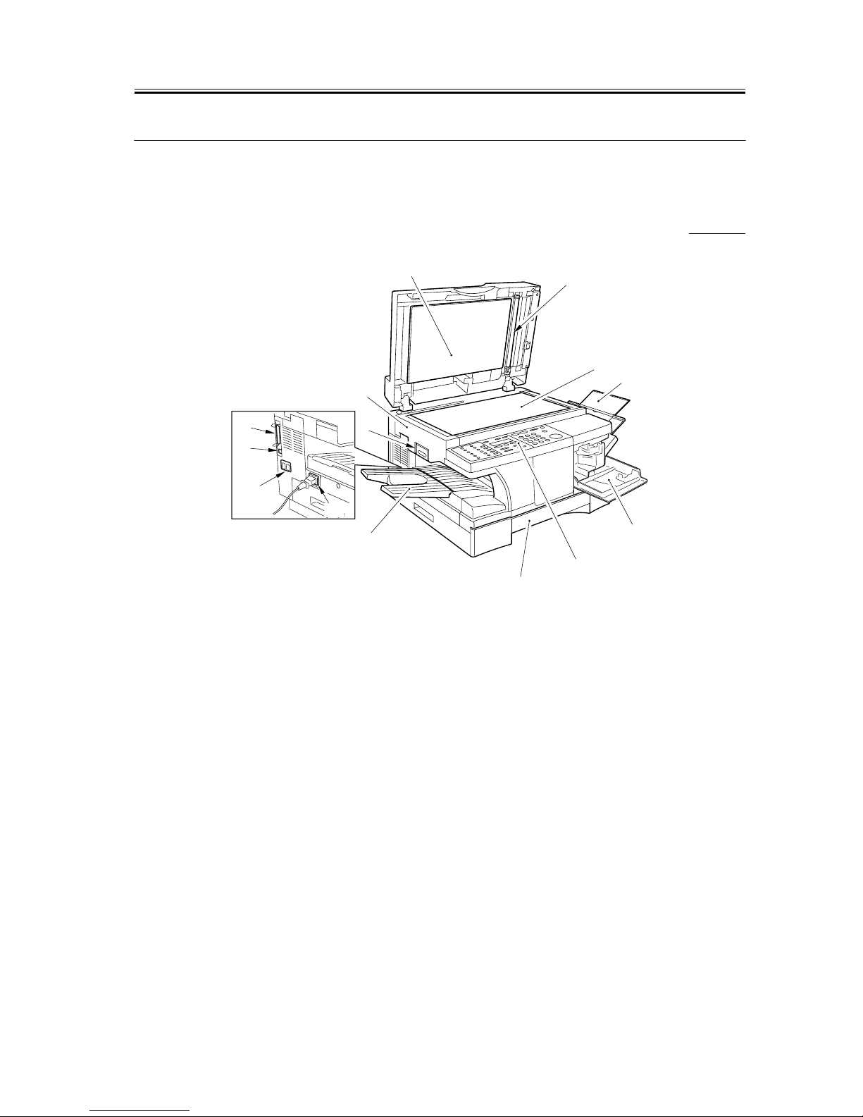
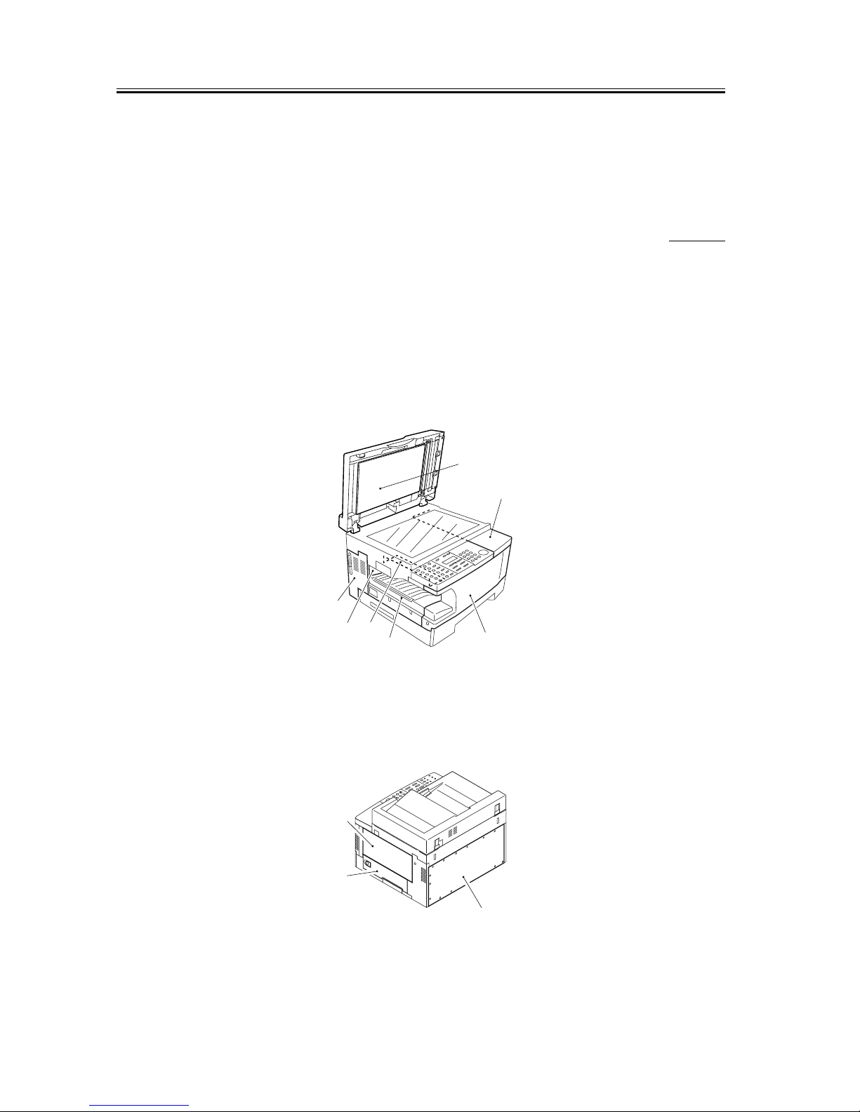
1.1.1.1 External View (ADF type) 0006-2706
F-1-1
T-1-1
*1: If equipped with fax functions.
[1] Reader unit slide lever [8] Control panel
[2] Reader unit [9] Cassette
[3] White sheet [10] Delivery tray
[4] White roller [11] Power cord connector assembly
[5] Copyboard glass [12] Modular cable connector
assembly*1
[6] Manual feed tray [13] USB cable connector assembly
[7] Toner supply cover [14] Parallel interface cable connector
assembly
[1]
[2]
[5]
[6]
[7]
[9]
[10]
[11]
[12]
[13]
[14]
[3]
[4]
[8]
Chapter 1
1-2
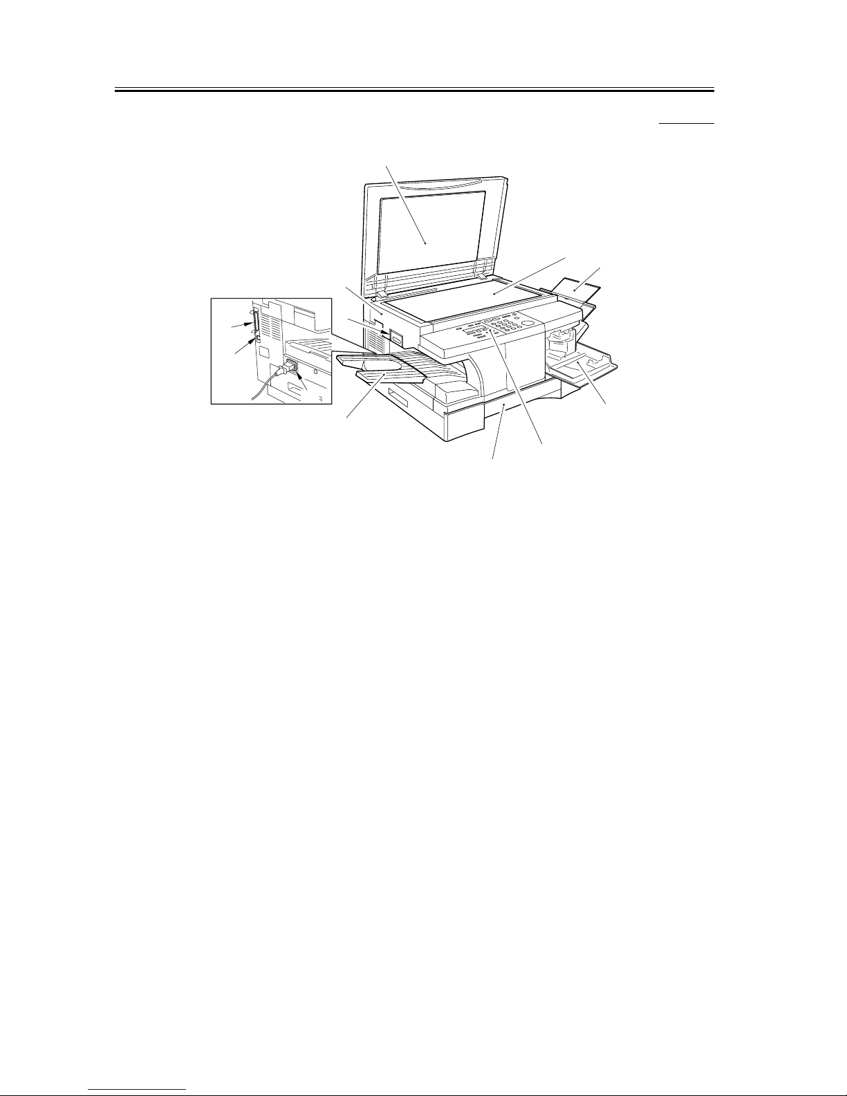
1.1.1.2 External View (copyboard type) 0006-2715
F-1-2
T-1-2
[1] Reader unit slide lever [7] Control panel
[2] Reader unit [8] Cassette
[3] Copyboard cover [9] Delivery tray
[4] Copyboard glass [10] Power cord connector assembly
[5] Manual feed tray [11] USB cable connector assembly
[6] Toner supply cover [12] Parallel interface cable connector
assembly
[1]
[2]
[6]
[7]
[10]
[12]
[11]
[3]
[4]
[5]
[8]
[9]
Chapter 1
1-3
F-1-3
T-1-3
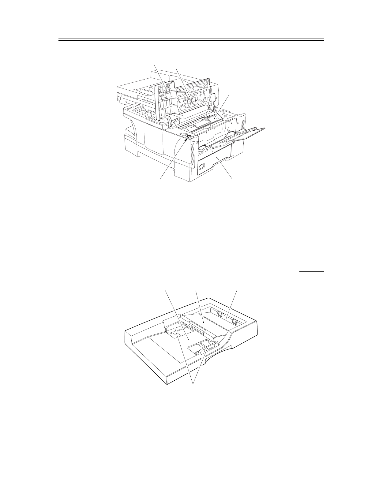
1.1.1.3 External View (ADF) 0006-2722
F-1-4
[1] Drum shutter stopper [4] Right door
[2] Cartridge cover [5] Shipping screw slot
[3] Cartridge
[4][5]
[2]
[3]
[1]
[4]
[3]
[2][1]
Chapter 1
1-4
T-1-4
1.1.1.4 External Covers 0007-3730
[1] ADF (copyboard cover)
[2] Cartridge cover
[3] Toner supply cover
[4] Front cover
[5] Delivery cover
[6] Delivery upper cover
[7] Delivery rear cover
[8] Left cover
F-1-5
[8] Right door
[9] Manual feed tray
[10] Rear cover
F-1-6
[1] Original placement area [3] Delivery slot
[2] Open/close cover [4] Slide guide
[7]
[2]
[3]
[6]
[4]
[5]
[1]
[8]
#
1
2
3
4
5
6
7
8
9
0
O
K
[10]
[9]
Chapter 1
1-5
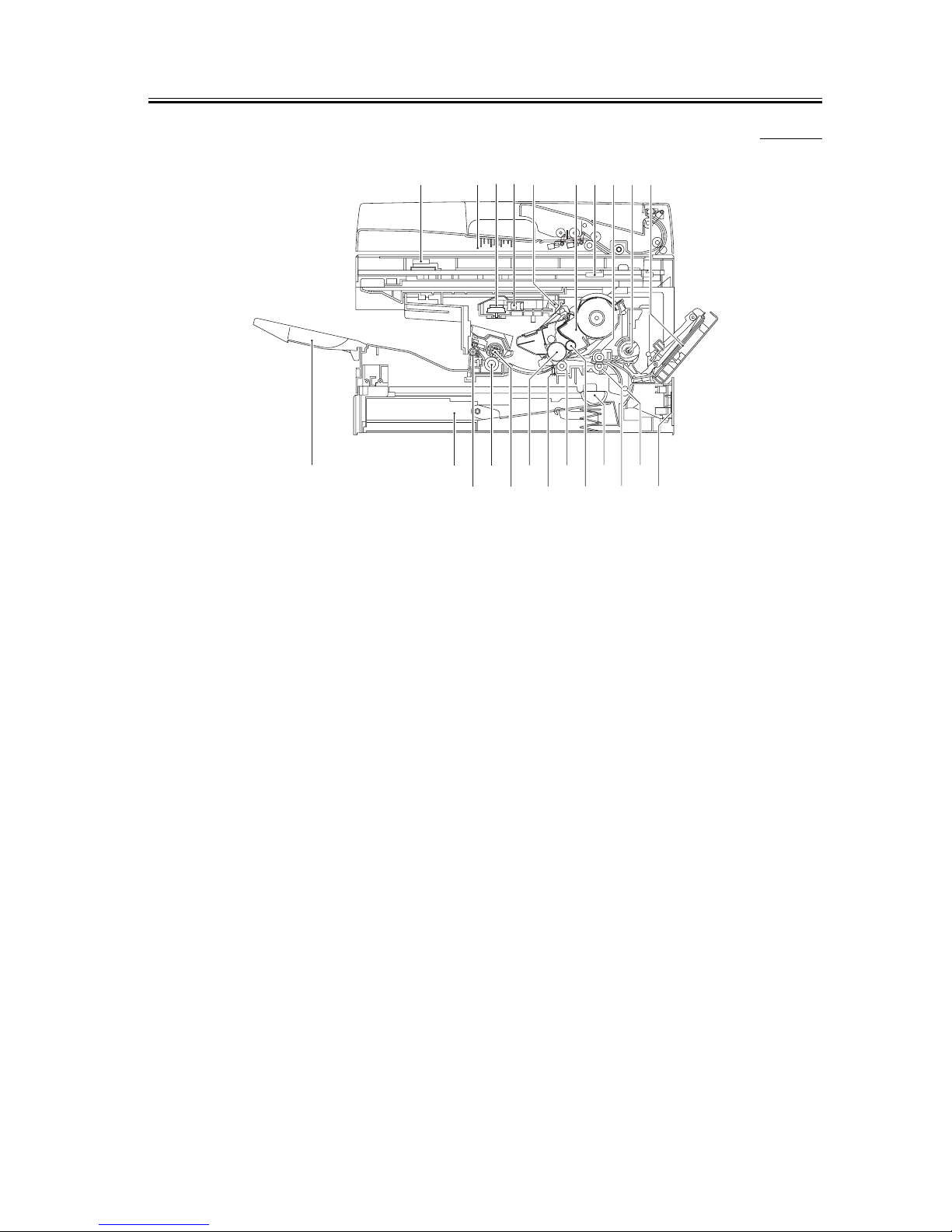
1.1.1.5 Cross Section (Body) 0006-2724
F-1-7
T-1-5
[1] Contact sensor [13] Registration roller
[2] Copyboard [14] Cassette pickup roller
[3] Laser scanner motor unit [15] Developing cylinder
[4] Laser unit [16] Transfer charging roller
[5] Reflecting mirror [17] Separation static eliminator
[6] Cartridge [18] Photopositive drum
[7] Reader unit [19] Fixing film unit
[8] Registration shutter [20] Fixing pressure roller
[9] Manual feed pickup roller [21] Delivery roller
[10] Manual feed tray [22] Cassette
[11] Right door [23] Delivery tray
[12] Vertical path roller
[1] [2][3][4][5] [6][7][8][9][10]
[23] [22] [20] [18] [16] [14] [12]
[21] [19] [17] [15] [13] [11]
Chapter 1
1-6
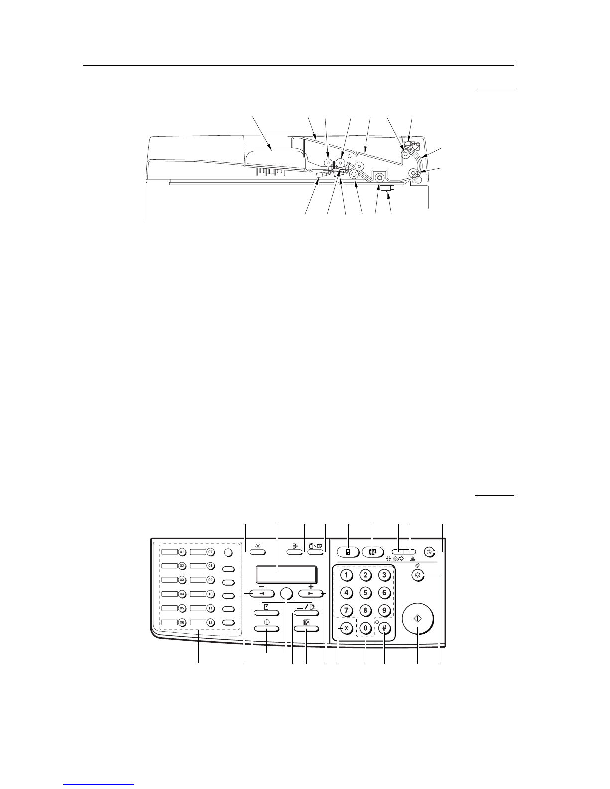
1.1.1.6 Cross Section (ADF) 0006-2770
F-1-8
T-1-6
1.1.2 Using the Machine
1.1.2.1 Control Panel 0006-2629
F-1-9
[1] Slide guide [9] Original feed roller
[2] Open/close cover [10] Contact sensor (body)
[3] Original pickup roller [11] White roller
[4] Original feed/separation roller [12] ADF registration roller
[5] Original delivery tray [13] Registration sensor
[6] Original delivery roller [14] Original separation pad
[7] Original delivery sensor [15] Original sensor
[8] Delivery external guide
[1] [2] [3] [4] [5] [6] [7]
[8
[9
[10][11][12][13][14][15]
ABC DEF
GHI
JKL
MNO
PQRS TUV WXYZ
Report
Memory
Reference
Fax Monitor
Delayed
Transmission
Book Sending
Clear
Delete
Space
Tone/+
Function
Redial / Pause
Coded Dial
Directory
Receive Mode
Fax Resolution
D.T.
R
[1] [2] [3] [4] [5] [6] [7] [8] [9]
[10][11]
[13]
[14][21] [15][16]
[19][20]
[22]
[17]
[18]
[12]
OK

Chapter 1
1-7
T-1-7
[1] Additional Functions Key
Press it to bring up the user mode menu for making various settings and
registering items. The key flashes when the machine is in user mode
menu, and goes OFF in response to a press.
[2] LCD
Use it to refer to the Copy/Fax basic screen, various Settings screens,
and error messages.
[3] Collate Key
Press it to select sorting. The key remains ON when the machine is in
sort mode, and goes OFF in response to a press.
[4] 2 on 1 Key
Press it to reduce 2 originals automatically and on a single sheet.
[5] Copy Key*1
Press it when using a copier function. The key remains ON when the
machine is in copier mode.
[6] Fax Key*1
Press it when using a fax function. The key remains ON when the
machine is in fax mode.
*1: If equipped with fax functions.
[7] In Use/Memory Lamp*1
It goes ON when an original has been read, a delayed fax transmission
has been selected, or memory reception has been used. Further, it flashes
while fax transmission is under way.
[8] Alarm Lamp
It flashes when a fault has occurred in the machine (e.g., paper jam).
[9] Energy Saver Key
Press it to manually select or deselect energy save mode. It remains ON
when the machine is in energy save mode, and goes OFF when the
machine leaves the mode.
[10] Stop/Reset Key
Press it to stop making copies or transmitting a fax. Or, press it to reset
the machine white making mode settings (i.e., to return copier/fax mode
to standard mode).

Chapter 1
1-8
[11] Start Key
Press it to start making a copy or sending a fax.
[12] # Key
Press it to enter a "symbol"when registering fax/telephone number or
when entering a fax telephone number.
[13] Keypad
Use it to enter a copy count or a value for Zoom, or when entering a fax
telephone number.
[14] * Key
Press it to generate a tone signal from a dial (pulse) circuit when using a
fax function.
[15] Right Arrow/+ Key
Press it to add a value when making various settings or to indicate the
next setting or an item.
[16] Image Quality Key
Press it to select a copy image quality type (text, text/photo, photo).
[17] Paper Select Key
Press it to select a source of paper (drawer (cassette), stack bypass
(manual feed)).
[18] OK Key (Set Key*2)
Press it to store various selections or settings.
[19] Exposure Key
Press it to change the copy density. (auto, or manual from 9 steps)
[20] Enlarge/Reduce Key
Press it to select a default Enlarge/Reduce ratio or Zoom.
[21] Left Arrow/- Key
Press it to subtract a value when making various settings or to indicate
the previous setting or an item.
[22] One-Touch/Fax Function Key (after a press on the Function key)*1
Press it to dial a pre-registered telephone number. A press on the
Function key will cause it to serve as the Fax Function key.
*1: If equipped with fax functions.
Chapter 1
1-9
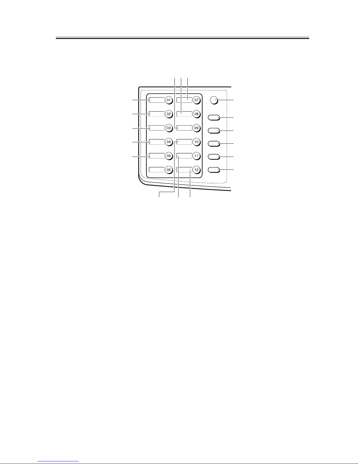
F-1-10
T-1-8
*2: Only for the iR1310/1330/1370F models.
[1] Tone/+ Key*1
Press it to generate a tone from a dial circuit. Press it to enter a + symbol
when registering a telephone number.
[2] D.T. Key*1
Press it to use a D.T. function.
[3] R Key*1
Press it to use an R function.
[4] Function Key*2
Press it to use the function key. A press on the Function key will cause
the key to go ON, and another press will cause it to go OFF.
[5] Redial/Pause Key*2
Press it to redial a number that has been dialed using the keypad (as in
fax wait). When entering a telephone number, it services as a Pause key.
*1: Function key is ON.
[1] [2] [3]
[17]
[16]
[15]
[14]
[13]
[4]
[5]
[6]
[7]
[8]
[9]
[12] [11] [10]
Report
Memory
Reference
Fax Monitor
Delayed
Transmission
Book Sending
Clear
Delete
Space
Tone/+
Function
Redial / Pause
Coded Dial
Directory
Receive Mode
Fax Resolution
D.T.
R

Chapter 1
1-10
*2: If equipped with fax functions.
[6] Coded Dial Key*1
Press it to use speed dialing.
[7] Directly Key*1
Use it to search for a one-touch or speed number using a name.
[8] Receive Mode Key*1
Press it to change the reception mode (faxtel, faxonly, DPRD*3, manual,
ansmode).
[9] FAX Resolution Key*1
Use it to change the transmission resolution (standard, fine, photo, super
fine, ultra fine).
[10] Clear Key*2
Press it to clear various settings that have been registered or made. Also,
press it to delete all telephone number/text input.
[11] Delete Key*2
Use it to delete a single character input.
[12] Space Key*2
Press it to put a space in a telephone number or a string of characters.
[13] Book Send Key*2
Press it to transmit multiple originals using the copyboard glass.
[14] Delayed Transmission Key*2
Press it to set a transmission time.
[15] Report Key*2
Press it to print out a communication-related report, dial list, user data
list, or document memory list.
[16] Memory Reference Key*2
Press it to check the file that has been processed by memory transmission
or memory reception.
[17] Fax Monitor Key*2
Press it to check the state of a fax communication.
*1: If equipped with fax functions.

Chapter 1
1-11
1.1.3 User Mode Items
1.1.3.1 Outline 0006-2653
A press on the Additional Functions key in the control panel brings up the user mode menu. On the user mode menu,
press the left/right arrow key to make menu settings or increase/decrease a value; press the OK key to store the
selected input.
The user mode menu is constructed as follows:
(The factory default setting is in bold face.)
1.1.3.2 COMMON SETTINGS 0007-1172
1. DEFAULT SETTINGS*1
T-1-9
2. SW AFTER AUTO CLR*1
T-1-10
3. VOLUME CONTROL*1
T-1-11
*2: Function key is ON.
*3: Only for the iR1370F model.
COPY
FAX
DEFAULT MODE
CURRENT MODE
1.KEYPAD
VOLUME
ON
VOLUME1 to 3 (1)
OFF

Chapter 1
1-12
*1: Only if equipped with fax functions.
T-1-12
2.ALARM
VOLUME*1
ON
VOLUME1 to 3 (1)
OFF
3.TX DONE TONE
ON
VOLUME1 to 3 (1)
ERROR ONLY
VOLUME1 to 3 (1)
OFF
4.RX DONE TONE
ON
VOLUME1 to 3 (1)
ERROR ONLY
VOLUME1 to 3 (1)
OFF
5.PRINTING END TONE
ON
VOLUME1 to 3 (1)
ERROR ONLY
VOLUME1 to 3 (1)
OFF
6.SCANNING END TONE
ON
VOLUME1 to 3 (1)
ERROR ONLY
 Loading...