

SERVICE
imageCLASS
Rev. 1
COPYRIGHT © 2018 CANON INC.
CANON imageCLASS M F 260dw Series Rev. 1 PRINTED IN U.S.A.
MF269dw
MF267dw
MF264dw
MANUAL
C an o n
June 6, 2018

1x
1x
Important Notices
Important Notices
Application
This manual has been issued by Canon Inc. for qualified persons to learn technical theory, installation, maintenance, and repair
of products.
This manual covers all localities where the products are sold. For this reason, there may be information in this manual that does
not apply to your locality.
Corrections
This manual may contain technical inaccuracies or typographical errors due to improvements or changes in products.
When changes occur in applicable products or in the contents of this manual, Canon will release technical information as the
need arises. In the event of major changes in the contents of this manual over a long or short period, Canon will issue a new
edition of this manual.
The following paragraph does not apply to any countries where such provisions are inconsistent with local law.
Trademarks
The product names and company names used in this manual are the registered trademarks of the individual companies.
Copyright
The copyright of this document belongs to Canon Inc. This document may not be copied, reproduced or translated into another
language, in whole or in part, without the prior consent of Canon Inc.
Copyright CANON INC. 2018
Caution
Use of this manual should be strictly supervised to avoid disclosure of confidential information.
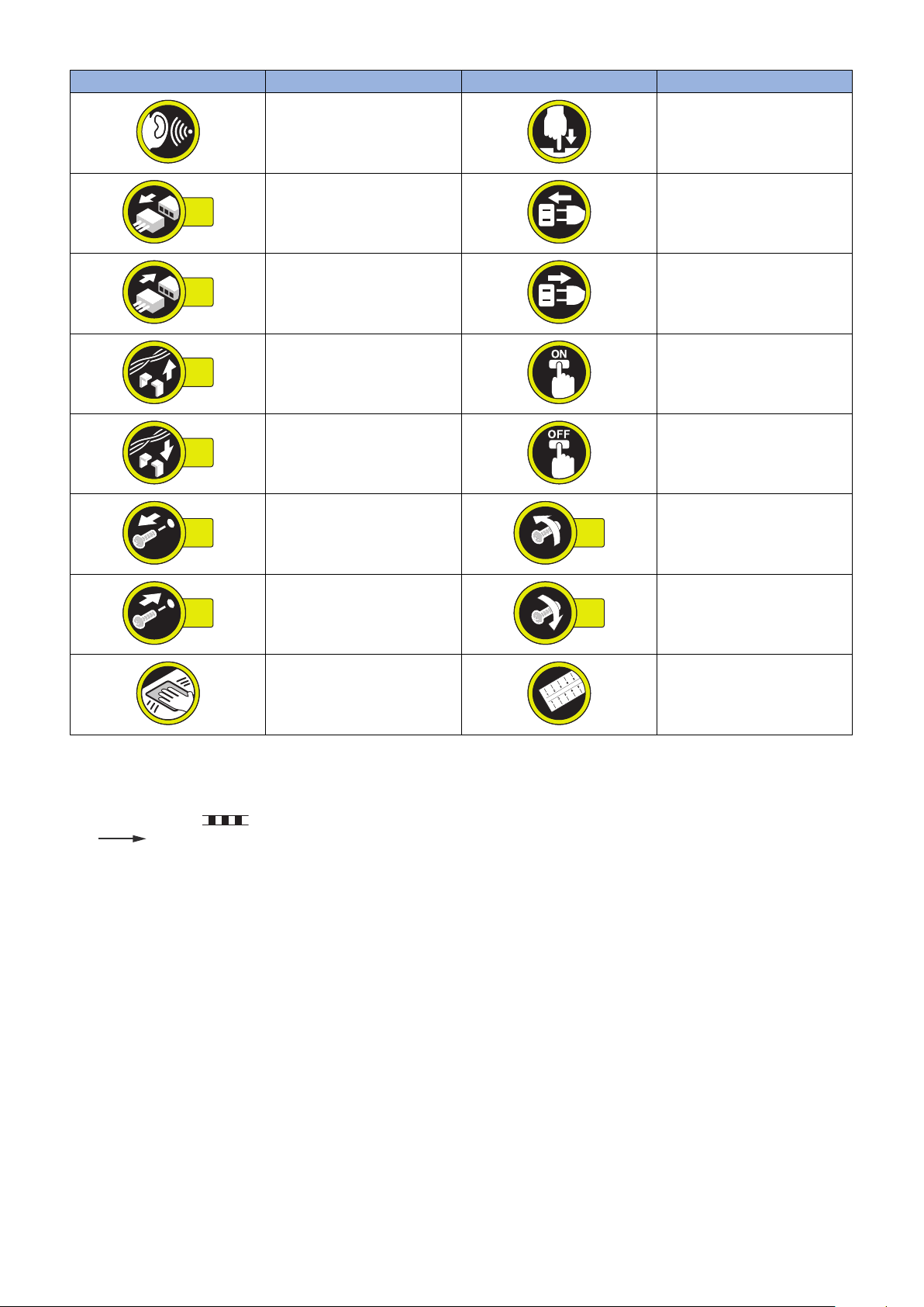
Explanation of Symbols
The following symbols are used throughout this Service Manual.
Symbols Explanation Symbols Explanation
Check.
Check visually.
Remove the claw.
Insert the claw.
1x
1x
1x
1x
1x
1x
1x
1x
Important Notices
Symbols Explanation Symbols Explanation
Check a sound. Push the part.
Disconnect the connector. Connect the power cable.
Connect the connector. Disconnect the power cable.
Remove the cable/wire from the
cable guide or wire saddle.
Install the cable/wire to the cable
guide or wire saddle.
Remove the screw.
Install the screw.
Cleaning is needed. Measurement is needed.
The following rules apply throughout this Service Manual:
1. Each chapter contains sections explaining the purpose of specific functions and the relationship between electrical and
mechanical systems with reference to the timing of operation.
In the diagrams, represents the path of mechanical drive; where a signal name accompanies the symbol, the arrow
indicates the direction of the electric signal.
The expression "turn on the power" means flipping on the power switch, closing the front door, and closing the delivery unit
door, which results in supplying the machine with power.
2. In the digital circuits, '1' is used to indicate that the voltage level of a given signal is "High", while '0' is used to indicate "Low".
(The voltage value, however, differs from circuit to circuit.) In addition, the asterisk (*) as in "DRMD*" indicates that the DRMD
signal goes on when '0'.
In practically all cases, the internal mechanisms of a microprocessor cannot be checked in the field. Therefore, the operations
of the microprocessors used in the machines are not discussed: they are explained in terms of from sensors to the input of
the DC controller PCB and from the output of the DC controller PCB to the loads.
The descriptions in this Service Manual are subject to change without notice for product improvement or other purposes, and
major changes will be communicated in the form of Service Information bulletins.
All service persons are expected to have a good understanding of the contents of this Service Manual and all relevant Service
Information bulletins and be able to identify and isolate faults in the machine.
Turn on the power.
Turn off the power.
Loosen the screw.
Tighten the screw.

Contents
Contents
Safety Precautions...............................................................................................1
Laser Safety........................................................................................................................................ 2
How to Handle the Laser Scanner Unit...............................................................................................2
Power Supply...................................................................................................................................... 2
Toner Safety........................................................................................................................................3
About Toner..........................................................................................................................................3
Handling Adhered Toner........................................................................................................................3
Notes When Handling a Lithium Battery............................................................................................. 3
Notes Before it Works Serving............................................................................................................ 3
Points to Note at Cleaning...................................................................................................................4
Notes on Assembly/Disassembly........................................................................................................4
1. Product Overview.............................................................................................5
Product Lineup.................................................................................................................................... 6
Host machine........................................................................................................................................6
Option.................................................................................................................................................. 7
Features.............................................................................................................................................. 8
Specifications...................................................................................................................................... 9
Product Specifications...........................................................................................................................9
Reader Specifications:.........................................................................................................................10
ADF Specifications (DADF/SADF)........................................................................................................11
FAX specification................................................................................................................................ 11
Paper Type.........................................................................................................................................12
Paper Size..........................................................................................................................................12
Parts Name....................................................................................................................................... 14
External view...................................................................................................................................... 14
Cross Section View............................................................................................................................. 17
Control Panel......................................................................................................................................20
2. Technology..................................................................................................... 22
Basic Configuration........................................................................................................................... 23
Functional Configuration......................................................................................................................23
Document Exposure/Feeder System................................................................................................ 24
Document Exposure System................................................................................................................24
Document Feeder System................................................................................................................... 24
Controller System..............................................................................................................................31
Functional Configuration......................................................................................................................31
Main Controller PCB............................................................................................................................31
Engine Controller PCB.........................................................................................................................32
Motor Control......................................................................................................................................34
Door Open Detection...........................................................................................................................34
Fan Control.........................................................................................................................................35
Power supply...................................................................................................................................... 36
Protection Function............................................................................................................................. 37
i

Contents
Power-saving Mode.............................................................................................................................37
Laser Exposure System.................................................................................................................... 39
Functional Configuration......................................................................................................................39
Failure Detection.................................................................................................................................39
Image Formation System.................................................................................................................. 41
Functional Configuration......................................................................................................................41
Image Formation Process....................................................................................................................42
Cartridge............................................................................................................................................ 42
High Voltage Power Supply Control......................................................................................................46
Fixing System....................................................................................................................................47
Functional Configuration......................................................................................................................47
Fixing temperature control................................................................................................................... 47
Protection Function............................................................................................................................. 48
Fixing Unit Failure Detection................................................................................................................ 49
Pickup Feed System......................................................................................................................... 50
Functional Configuration......................................................................................................................50
Parts Configuration..............................................................................................................................51
Paper detection...................................................................................................................................53
Pickup Control.................................................................................................................................... 53
Paper Width Detection.........................................................................................................................54
Paper Length Detection....................................................................................................................... 55
Jam Detection.....................................................................................................................................56
3. Periodical Service.......................................................................................... 57
Periodically Replaced Parts.............................................................................................................. 58
Consumable Parts.............................................................................................................................59
Periodical Service..............................................................................................................................60
Cleaning Parts...................................................................................................................................61
4. Parts Replacement and Cleaning................................................................. 62
Preface..............................................................................................................................................63
Outline............................................................................................................................................... 63
List of Parts....................................................................................................................................... 64
External Cover....................................................................................................................................64
Main Unit............................................................................................................................................68
Electrical Components List...................................................................................................................71
External Cover System .....................................................................................................................77
Removing the Cartridge.......................................................................................................................77
Removing the Right Cover...................................................................................................................78
Removing the Left Cover..................................................................................................................... 80
Removing the Front Cover...................................................................................................................83
Removing the Toner Cover.................................................................................................................. 86
Removing the Duplex Door.................................................................................................................. 90
Removing the Upper Cover..................................................................................................................91
Removing the Multi-purpose Tray ........................................................................................................91
Original Exposure/Feed System (DADF Model)................................................................................93
Removing the DADF Unit + Reader Unit............................................................................................... 93
Separating the DADF Unit + Reader Unit..............................................................................................96
Removing the DADF Pickup Unit..........................................................................................................99
ii

Contents
Removing the DADF Motor................................................................................................................ 103
Removing the DADF Solenoid............................................................................................................105
Removing the DADF Pickup Roller Unit.............................................................................................. 106
Removing the DADF Pickup Roller .................................................................................................... 109
Removing the DADF Separation Roller .............................................................................................. 110
Removing the DADF Separation Pad..................................................................................................112
Removing the Copyboard Glass (DADF Model)...................................................................................115
Removing the Contact Image Sensor (DADF Model)........................................................................... 117
Removing the Reader Motor (DADF Model)........................................................................................ 122
Original Exposure/Feed System (SADF Model)..............................................................................126
Removing the SADF Unit + Reader Unit............................................................................................. 126
Separating the SADF Unit + Reader Unit............................................................................................ 129
Removing the SADF Upper Cover Unit............................................................................................... 131
Removing the SADF Pickup Unit........................................................................................................ 134
Removing the SADF Motor................................................................................................................ 135
Removing the SADF Pickup Roller Unit.............................................................................................. 137
Removing the SADF Pickup Roller .................................................................................................... 140
Removing the SADF Separation Roller .............................................................................................. 141
Removing the SADF Separation Pad..................................................................................................143
Removing the Copyboard Glass (SADF Model)...................................................................................146
Removing the Contact Image Sensor (SADF Model)............................................................................148
Removing the Reader Motor(SADF Model)......................................................................................... 153
Original Exposure/Feed System (Copyboard Model)......................................................................157
Removing the Copyboard Cover.........................................................................................................157
Removing the Copyboard Cover + Reader Unit...................................................................................157
Removing the Platen Glass (Copyboard Model).................................................................................. 161
Removing the Contact Image Sensor (Copyboard Model).................................................................... 163
Removing the Reader Motor (Copyboard Model).................................................................................168
Controller System ...........................................................................................................................172
Removing the Control Panel Unit .......................................................................................................172
Removing the Wireless Lan PCB .......................................................................................................173
Removing the Main Controller PCB ................................................................................................... 173
Removing the Low-Voltage Power Supply Unit....................................................................................176
Removing the Engine Controller PCB ................................................................................................ 181
Removing the Motor PCB ................................................................................................................. 184
Removing the Environment/Pickup Sensor PCB .................................................................................185
Removing the Main Fan.....................................................................................................................187
Removing the Speaker (Fax Model)....................................................................................................188
Removing the NCU PCB (Fax Model).................................................................................................190
Laser Exposure System.................................................................................................................. 192
Removing the Laser Scanner Cover................................................................................................... 192
Removing the Laser Scanner Unit...................................................................................................... 194
Image Formation System................................................................................................................ 196
Removing the Transfer Roller.............................................................................................................196
Removing the Transfer Unit............................................................................................................... 197
Removing the Developer Disengagement Solenoid............................................................................. 202
Fixing System..................................................................................................................................204
Removing the Fixing Unit...................................................................................................................204
Removing the Fixing Film Unit ...........................................................................................................207
Pickup Feed Delivery System......................................................................................................... 211
Removing the Pickup Roller .............................................................................................................. 211
iii

Contents
Removing the Separation Pad Unit.....................................................................................................211
Removing the Duplex Frame Unit.......................................................................................................212
Removing the Duplex Reverse Unit ................................................................................................... 217
Removing the Top Sensor PCB .........................................................................................................218
Removing the Delivery Sensor PCB .................................................................................................. 219
5. Adjustment................................................................................................... 220
Adjustment at Parts Replacement...................................................................................................221
Main Controller PCB..........................................................................................................................221
Control Panel Unit Touch Panel Model ...............................................................................................221
6. Troubleshooting...........................................................................................222
Test Print.........................................................................................................................................223
Engine Test Print...............................................................................................................................223
Table of Report................................................................................................................................. 223
Cartridge Log Report......................................................................................................................... 223
Troubleshooting Items.....................................................................................................................226
Remedy for Image Failure..................................................................................................................226
Recurring faulty image.......................................................................................................................226
Confirming Nip Width.........................................................................................................................226
Debug Log.......................................................................................................................................228
Function Overview.............................................................................................................................228
Firmware Log Collection Using Log Collection Tool............................................................................. 228
Version Upgrade............................................................................................................................. 231
Function Overview.............................................................................................................................231
Version Upgrade Using UST.............................................................................................................. 231
Version Upgrade via Internet..............................................................................................................231
7. Error/Jam/Alarm........................................................................................... 234
Overview......................................................................................................................................... 235
Outline of Codes............................................................................................................................... 235
Error/Jam Log Indication....................................................................................................................235
Error Code.......................................................................................................................................238
Error Code Details.............................................................................................................................238
Jam Code........................................................................................................................................241
Jam Code Table (Host Machine)........................................................................................................ 241
Table of Jam Code (ADF).................................................................................................................. 241
Alarm Code..................................................................................................................................... 243
8. Service Mode................................................................................................ 244
Overview......................................................................................................................................... 245
Entering Service Mode...................................................................................................................... 245
COPIER (Service mode for printer).................................................................................................246
DISPLAY (State display mode)...........................................................................................................246
I/O (I/O display mode)........................................................................................................................248
ADJUST (Adjustment mode).............................................................................................................. 248
FUNCTION (Operation / inspection mode).......................................................................................... 251
OPTION (Specification setting mode)................................................................................................. 257
iv

Contents
COUNTER (Counter mode)............................................................................................................... 261
FEEDER (ADF service mode).........................................................................................................265
ADJUST (Adjustment mode).............................................................................................................. 265
FUNCTION (Operation / inspection mode).......................................................................................... 265
FAX (FAX service mode).................................................................................................................266
SSSW (Bit switch registration mode).................................................................................................. 266
MENU (Menu switch registration mode).............................................................................................. 268
NUM (Numeric parameter setting mode).............................................................................................269
NCU (NCU parameter setting mode).................................................................................................. 270
TESTMODE (Service mode for test print, operation check, etc.)....................................................274
SYSTEM (SYSTEM Test Mode).........................................................................................................274
SCAN (SCAN Test Mode)..................................................................................................................274
FAX (FAX test mode).........................................................................................................................277
PANEL (PANEL Test Mode)...............................................................................................................278
APPENDICES....................................................................................................279
Service Tools...................................................................................................................................280
Special Tools.................................................................................................................................... 280
Solvents and Oil List..........................................................................................................................280
General Circuit Diagram..................................................................................................................281
General Circuit Diagram(1/2)..............................................................................................................281
General Circuit Diagram(2/2)..............................................................................................................282
Backup Data....................................................................................................................................283
Backup Data..................................................................................................................................... 283
v

Safety Precautions
Laser Safety..........................................2
How to Handle the Laser Scanner Unit
...........................................................2
Power Supply........................................2
Toner Safety..........................................3
Notes When Handling a Lithium
Battery............................................... 3
Notes Before it Works Serving..............3
Points to Note at Cleaning.................... 4
Notes on Assembly/Disassembly..........4
Safety Precautions
Laser Safety
Since radiation emitted inside this machine is completely confined with protective housings and external covers, the laser beam
cannot escape from the machine during any phase of normal use by users.
Therefore, this machine is classified as a Class 1 laser product under the international standard IEC60825-1 that is regarded as
safe during normal use.
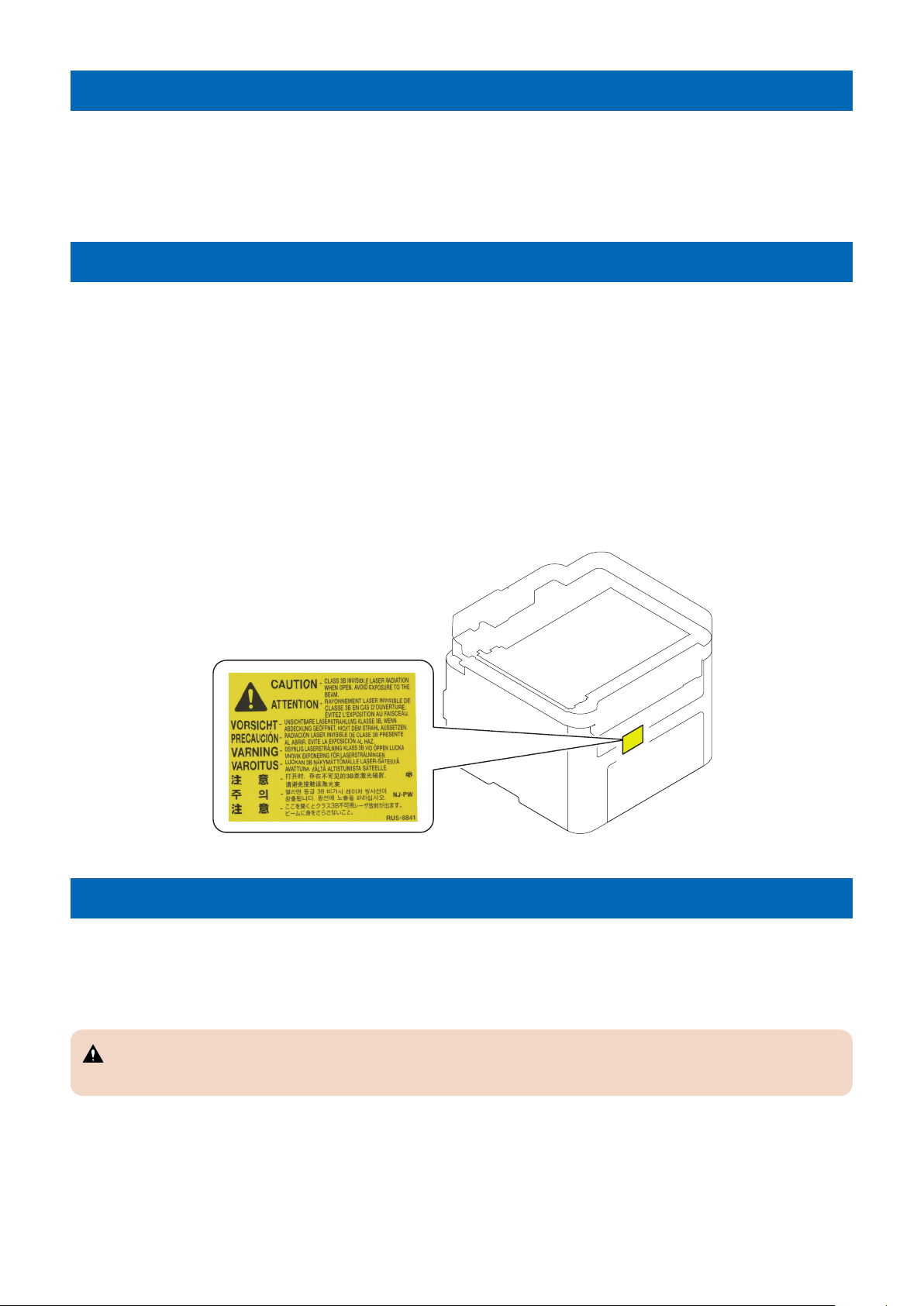
How to Handle the Laser Scanner Unit
This machine is classified as a Class 1 laser product.
However, the laser scanner unit contains source of Class 3B laser beam and exposure to the beam may cause eye injuries.
Therefore, be sure not to disassemble the laser scanner unit. No adjustment can be made to the laser scanner unit in the machine
in the field.
The mark or the warning label shown in the following figure is affixed on the laser scanner unit.
Dieses Gerät ist der Klasse 1 der Laserprodukte zugeordnet.
Allerdings enthält die Laserscannereinheit eine Laserstrahlquelle der Klasse 3B, die Augenschäden verursachen kann, wenn
man in diesen Strahl blickt.
Deshalb darf die Laserscannereinheit nicht zerlegt werden. An der Laserscannereinheit kann keine Justage vor Ort vorgenommen
werden.
Das in dem folgenden Bild dargestellte Kennzeichen bzw. der Warnaufkleber ist auf der Laserscannereinheit angebracht.
Power Supply
• As a general rule, do not use extension cords.
If an extension cord must be used, however, use one for local rated voltage and over, untie the cord binding, and insert the
power plug completely into the extension cord outlet to ensure a firm connection between the power cord and the extension
cord.
CAUTION:
Do not plug multiple cords together to an extension cord. It may cause a fire or electrical shock.
• The socket-outlet shall be installed near the equipment and shall be easily accessible.
2
Safety Precautions
Toner Safety
About Toner
Toner is a nontoxic matter composed of plastic, iron and a trace of pigments.
CAUTION:
Never throw toner in flames to avoid explosion.
Handling Adhered Toner
• Use dry tissue paper to wipe off toner adhered to skin or clothes and wash in water.
• Never use warm water for cleaning up toner to prevent toner particles from being gelated to soak into fibers permanently.
• Toner particles are reactive with vinyl polymers. Avoid contacting these materials.
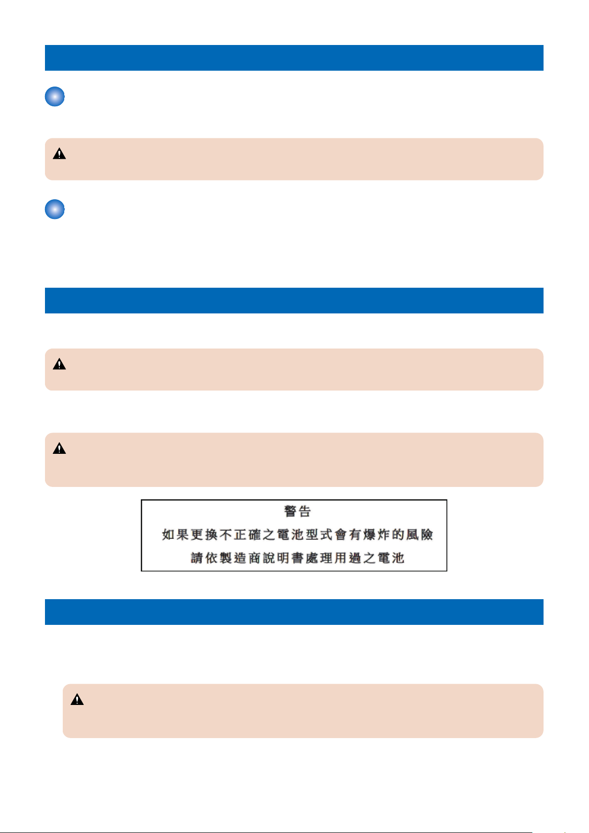
Notes When Handling a Lithium Battery
Dispose of used batteries according to the instructions.
CAUTION:
Risk of explosion if battery is replaced by an incorrect type.
The following warnings are given to comply with Safety Principles (EN60950-1).
CAUTION:
Wenn mit dem falschen Typ ausgewechselt, besteht Explosionsgefahr.
Gebrauchte Batterien gemäß der Anleitung beseitigen.
Notes Before it Works Serving
• At servicing, be sure to turn OFF the power source according to the specified steps and disconnect the power plug.
• Be sure to disconnect the power plug on a regular basis and remove dust and dirt accumulated around the outlet with dry
cloth.
CAUTION:
Leaving the power plug connected for a long time in an environment having a lot of dust, moisture, or oily smoke will
cause a fire. (Because dust accumulated in the surrounding area will absorb moisture and cause an insulation failure)
3

Safety Precautions
Points to Note at Cleaning
When performing cleaning using organic solvent such as alcohol, be sure to check that the component of solvent is vaporized
completely before assembling.
Notes on Assembly/Disassembly
Follow the items below to assemble/disassemble the device.
1. Disconnect the power plug to avoid any potential dangers during assembling/disassembling works.
2. If not specially instructed, reverse the order of disassembly to reinstall.
3. Ensure to use the right screw type (length, diameter, etc.) at the right position when assembling.
4. To keep electric conduction, binding screws with washers are used to attach the grounding wire and the varistor. Ensure to
use the right screw type when assembling.
5. Unless it is specially needed, do not operate the device with some parts removed.
6. Never remove the paint-locked screws when disassembling.
CAUTION:
English
CAUTION
The fuse may be in the neutral, and that the mains shall be disconnected to de-energize the phase conductors.
German
VORSICHT
Die Sicherung kann sich im Nullleiter befinden und das Hauptnetz muss abgetrennt werden, um die Phasenleiter
stromlos zu machen.
4

1
Product Overview
Product Lineup......................................6
Features................................................8
Specifications........................................9
Parts Name......................................... 14
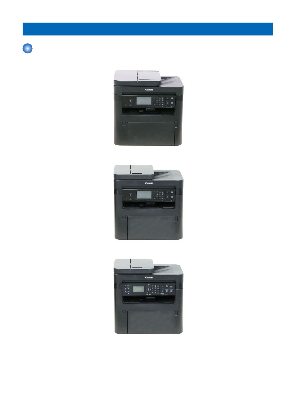
Product Lineup
Host machine
MF269dw
MF267dw / MF266dn
1. Product Overview
MF264dw / MF263dn
MF261d
6
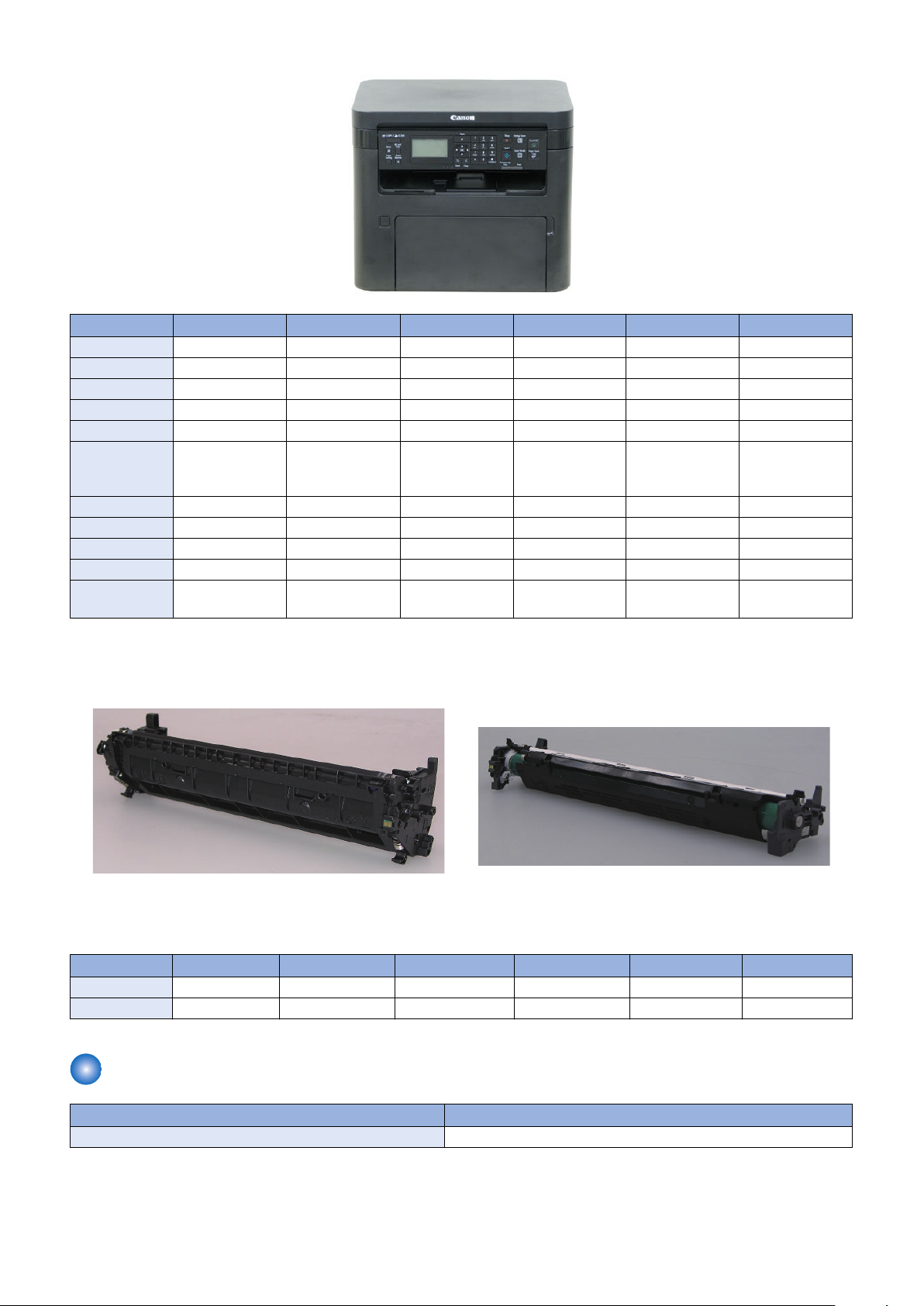
[1] [2]
1. Product Overview
Item MF269dw MF267dw MF266dn MF264dw MF263dn MF261d
Copy Yes Yes Yes Yes Yes Yes
Print Yes Yes Yes Yes Yes Yes
Fax Yes Yes Yes - - -
Remote UI Yes Yes Yes Yes Yes Yes
2-sided printing Yes Yes Yes Yes Yes Yes
Control Panel 6-lined LCD +
Touch Panel + Numeric Keys
ADF DADF SADF SADF SADF SADF -
MEAP - - - - - -
Wired LAN Supported Supported Supported Supported Supported -
Wireless LAN Supported Supported - Supported - -
Cartridge *1 Drum separated
type
6-lined LCD +
Touch Panel + Numeric Keys
Drum separated
type
6-lined LCD +
Touch Panel + Numeric Keys
Drum separated
type
5 lined LCD + Numeric keys
Drum separated
type
5 lined LCD + Numeric keys
Drum separated
type
5 lined LCD + Numeric keys
Drum separated
type
*1: Cartridge configuration
• [1]: Toner Cartridge (Developing Assembly / Toner)
• [2]: Drum Cartridge (Drum)
PDL
MF269dw MF267dw MF266dn MF264dw MF263dn MF261d
UFR II-LT Yes Yes Yes Yes Yes Yes
PCL6/5e Yes Yes Yes Yes Yes Yes
Option
Name Remarks
TELEPHONE 6 KIT Black FAX Model (excluding CHN, KOR and US)
7

1. Product Overview
Features
Improved productivity
Print speed of 28 ppm (A4)/30 ppm (LTR) in 1-sided printing has been achieved.
Supports Automatic 2-sided print
Automatic 2-sided print function on all models
Control Panel with a large screen excellent in visibility and operability
Equipped with usability considered Control Panel with 6-line black and white Touch Panel (MF269dw/MF267dw/MF266dn)
Drum separated type Cartridge
Configuration of Toner Cartridge (Developing Assembly + Toner) and Drum Cartridge (Drum)
8

1. Product Overview
Specifications
Product Specifications
Item Specification/Function
Machine installation method Desktop
Photosensitive medium OPC Drum (20 mm dia.)
Exposure method Laser beam exposure
Charging method Roller charging
Developing method Contact development
Transfer method Roller transfer
Separation method Curvature separation
Paper feed method Pad separation method
Multi-purpose Tray pickup
method
Drum cleaning method None
Transfer cleaning method None
Fixing method On-demand fixing
Paper delivery method Face-down
Toner level detection function None
Toner type One-component magnetic toner
Toner supplying method Supply by Toner Cartridge replacement
Toner save mode Available
Warm-up time *1 15 sec. or less
Print resolution 600 x 600 dpi
First copy time ADF model:
First print time 5.2 seconds (A4), 5.1 seconds (LTR)
Print speed *2 At 1-sided printing:
Paper types for Pickup Tray Plain paper, Recycled paper, Heavy paper, Bond paper, Label paper, Envelope
Multi-purpose Tray paper type Plain paper, Recycled paper, Heavy paper, Bond paper, Label paper, Envelope
Pickup Tray paper size A4R, B5R, A5, A5R, A6R, LGLR, LTRR, STMTR, EXECR, OFFICIOR, B-OFFICIOR, M-OFFICIOR,
Multi-purpose Tray paper size A4R, B5R, A5, A5R, A6R, LGLR, LTRR, STMTR, EXECR, OFFICIOR, B-OFFICIOR, M-OFFICIOR,
Pickup Tray capacity
Multi-purpose Tray paper capacity
Delivery Tray capacity *3
Auto 2-sided printing Available
Memory capacity 256 MB
Pad separation method
• 11.0 seconds or less (A4), 10.8 seconds or less (LTR)
Copyboard model:
• 8.2 seconds or less (A4), 8.0 seconds or less (LTR)
• 28 pages/min (A4), 30 pages/min (LTR)
At 2-sided printing:
• 17.8 pages/min (A4), 18.4 pages/min (LTR)
GLTRR, G-LGLR, AFLS-R, FLS-R, 16KR, IndianLGLR, F4AR, Index Card (3x5inch), Envelope:
COM10, Monarch, C5, DL, custom paper (width 76.2 to 215.9 mm, length 127.0 x 356.0 mm)
GLTRR, G-LGLR, AFLS-R, FLS-R, 16KR, IndianLGLR, F4AR, Index Card (3x5inch), Envelope:
COM10, Monarch, C5, DL, custom paper (width 76.2 to 215.9 mm, length 127.0 x 356.0 mm)
Plain paper (60 to 80 g/m2): 250 sheets
Plain paper (81 to 90 g/m2): 170 sheets
Heavy paper (91 to 105 g/m2): 170 sheets
Heavy paper (106 to 163 g/m2): 100 sheets
Bond paper: 100 sheets
Recycled paper 100 sheets
Label paper: 100 sheets
Envelope: 10 sheets
Index card: 50 sheets
1 sheet (60 to 163 g/m2)
50 sheets (60 to 80 g/m2)
9
Item Specification/Function
Sleep mode Available
Allowable environmental temperature range
Allowable environmental humidity range
Rated power supply Rated input voltage
Maximum power consumption 1,080 W or less (120 V), 1,180 W or less (230 V)
Average power consumption
at operation
Average power consumption
at standby
Average power consumption
at sleep mode
Power consumption at Main
Power Switch OFF
Dimensions (width x depth x
height)
Weight Host machine:
10 to 30 deg C
20 to 80 % (Relative humidity; without dew condensation)
110 to 127 V (60 Hz)
220 to 240 V (50/60 Hz)
340 W or less (120 V), 340 W or less (230 V)
Approx. 5.4 W (120 V), approx. 5.7 W (230 V)
ADF model:
• Approx. 0.7 W (120 V), approx. 0.8 W (230 V)
Copyboard model:
• Approx. 0.5 W
0.5 W or less
ADF model:
• Approx. 390 mm x 405 mm x 375 mm
Copyboard model:
• Approx. 390 mm x 405 mm x 327 mm
• Approx. 13.3 kg (DADF model), approx. 12.4 kg (SADF model), approx. 10.8 kg (copyboard model)
Toner Cartridge
• Approx. 0.3 kg (small capacity), approx. 0.3 kg (medium capacity), approx. 0.4 kg (large capacity)
Drum Cartridge
• Approx. 0.2 kg
1. Product Overview
*1: The time from when the power is turned ON to when the basic screen appears. This may vary depending on the usage
conditions and environment of this machine.
*2: The print speed may become lower depending on the settings such as paper type / orientation, and number of sheets
printed.
*3: The actual stack capacity varies depending on the site environment and the type of paper used.
Reader Specifications:
Item Function/Method
Original Exposure LED
Scanning of original In book mode: Scan by moving the Contact Image Sensor (CIS)
When using the SADF/DADF: Stream scanning of the original with the Contact Image Sensor (CIS) fixed
Scanning resolution 600 dpi x 600 dpi
Number of gradations 256 gradations
Magnification ratio 25 % to 400 %
Horizontal scanning direction: Image processing by the Main Controller PCB
Vertical scanning direction: The speed at which the carriage moves and image processing by the Main
Controller PCB
Lens Rod lens array
CMOS Sensor Number of lines: 1
Number of pixels: Total 5184 (5126 effective number of pixels)
Max. original reading width: 216 mm
CIS drive control Drive control by the Reader Motor
Original size detection None
10

ADF Specifications (DADF/SADF)
Item Specifications
Original pickup method Auto pickup method
Original setting method Face up stacking
Original feed mode 1-sided, 2-sided
Original type Sheet document
Original size DADF Size: A4R/B5R/A5/B6 (landscape)/LGL/LTRR
For 2-sided, A4R/B5R/A5/B6 (landscape) only
• Feed direction: 127 mm to 356 mm
• Width direction: 140 mm to 216 mm
SADF Size: A4R/B5R/A5/B6 (landscape)/LGL/LTRR
• Feed direction: 105 mm to 356 mm
• Width direction: 148 mm to 216 mm
Original weight Continuous
feed
1 sheet
Feed
Paper capacity* (80
g/m2)
Original reference Center reference
Original scanning method Stream reading
Mixed paper Same configuration only
Original size detection function None
Function to automatically detect document density None
Stamp function None
Original feed speed
(at reading)
Original processing
speed (A4)
DADF S size: 50 sheets, L size: 10 sheets
SADF S size: 35 sheets, L size: 10 sheets
100% DADF: 129.34 mm/s
B/W Stream reading 300 dpi x 300 dpi
Color Stream reading 300 dpi x 300 dpi
1-Sided documents
2-Sided documents
1-Sided documents
50 g/m2 to 105 g/m
60 g/m2 to 105 g/m
50 g/m2 to 128 g/m
SADF: 113.38 mm/s
• DADF 1-sided: 22 ipm
• DADF 2-sided: 8 ipm
• SADF 1-sided: 20 ipm
• DADF 1-sided: 15 ipm
• DADF 2-sided: 5 ipm
• SADF 1-sided: 15 ipm
2
2
2
1. Product Overview
*:
S size: A4R, B5R, A5R, B6, LTRR, STMTR
L size: LGL
FAX specification
Item Specifications
Line Used Public Switched Telephone Network (PSTN) *1
Communication Mode Super G3, G3
Modem speed Super G3: 33.6 Kbps, G3: 14.4 Kbps
(With automatic fallback function)
Data compression method MH, MR, MMR
Transmission speed Approx. 3 sec. per page *2
(ECM-MMR, sent from the memory at 33.6 Kbps)
Send/receive memory Maximum approx. 256 pages*2 (Total pages of transmission/reception)
(Maximum number of fax jobs that can be sent from the memory: 10 jobs/Maximum number of fax jobs
that can be received into the memory: 90 jobs)
11
1. Product Overview
Item Specifications
Fax resolution • Normal: 200 x 100 dpi
• Fine: 200 x 200 dpi
• Photo: 200 x 200 dpi
• Superfine: 200 x 400 dpi
Dialing • One-touch keys (4 destinations)
• Coded dialing (100 destinations)
• Group dialing (103 groups)
• Address Book dialing
• Regular dialing (with numeric keys)
• Automatic redialing
• Manual redialing
• Sequential broadcast (114 destinations)
Receiving Automatic reception
Remote reception by telephone (Default ID: 25)
Reports • TX Result Report
• Transmission management report (auto output every 40 destinations)
• RX Result Report
Number Display Not supported
Telephone Type Handset (Optional)
External phone / Answering machine / Data modem
*1: The Public Switched Telephone Network currently supports 28.8 Kbps modem speed or lower. Note that speeds can vary
depending on the telephone line conditions.
*2: Based on ITU-T (ITU Telecommunication Standardization Sector) Standard Chart No. 1, MMR standard mode.
Paper Type
Type of paper Paper settings in this machine
Plain
Recycled
Heavy paper
Bond paper
Label paper - Labels
Envelope COM10, Monarch, C5, DL Envelope
2
60 g/m
61 to 70 g/m
71 to 89 g/m
71 to 89 g/m
90 to 105 g/m
106 to 120 g/m
121 to 163 g/m
121 to 163 g/m
60 to 104 g/m
105 to 163 g/m
COM10, Monarch, C5, DL Envelope H *2
2
2
2
2
2
2
2
2
2
Plain L2
Plain L
Plain
Recycled
Heavy 1
Heavy 2
Heavy 3
Heavy 4* 1
Bond 1
Bond 2
*1: Use this type when fixing performance is poor with heavy paper 3 or when using linen paper.
*2: Use this type when fixing performance is poor with envelope or when using linen envelope.
Paper Size
(Yes: Pickup possible, -: Pickup not possible)
Size Feeding direction (mm) Width direction (mm) Pickup position
Pickup tray Multi-Purpose tray
A4R 297.0 210.0 Yes Yes
B5R 257.0 182.0 Yes Yes
A5R 210.0 148.0 Yes Yes
A5 148.0 210.0 Yes Yes
A6 148.0 105.0 Yes Yes
12

Size Feeding direction (mm) Width direction (mm) Pickup position
Pickup tray Multi-Purpose tray
LGL 355.6 215.9 Yes Yes
LTRR 279.4 215.9 Yes Yes
STMTR 215.9 139.7 Yes Yes
EXECR 266.7 184.1 Yes Yes
OFFICIO 317.5 215.9 Yes Yes
B-OFFICIO 355.0 215.9 Yes Yes
M-OFFICIO 341.0 215.9 Yes Yes
G-LTR 266.7 203.2 Yes Yes
G-LGL 330.2 203.2 Yes Yes
AFLS 337.0 206.0 Yes Yes
FLS 330.2 215.9 Yes Yes
16KR 270.0 195.0 Yes Yes
Indian LGL 345.0 215.0 Yes Yes
F4A 342.9 215.9 Yes Yes
Index
Card(3x5inch
)
Envelope No.
10 (COM10)
Envelope
Monarch
Envelope C5 229.0 162.0 Yes Yes
Envelope DL 220.0 110.0 Yes Yes
Custom 127.0 to 355.6 76.2 to 215.9 Yes Yes
127.0 76.2 Yes Yes
241.3 104.7 Yes Yes
190.5 98.4 Yes Yes
1. Product Overview
13
Parts Name
[10]
[11]
[12]
[13]
[14]
[1]
[2]
[3]
[4]
[5]
[6]
[7]
[8]
[9]
[13]
[6]
External view
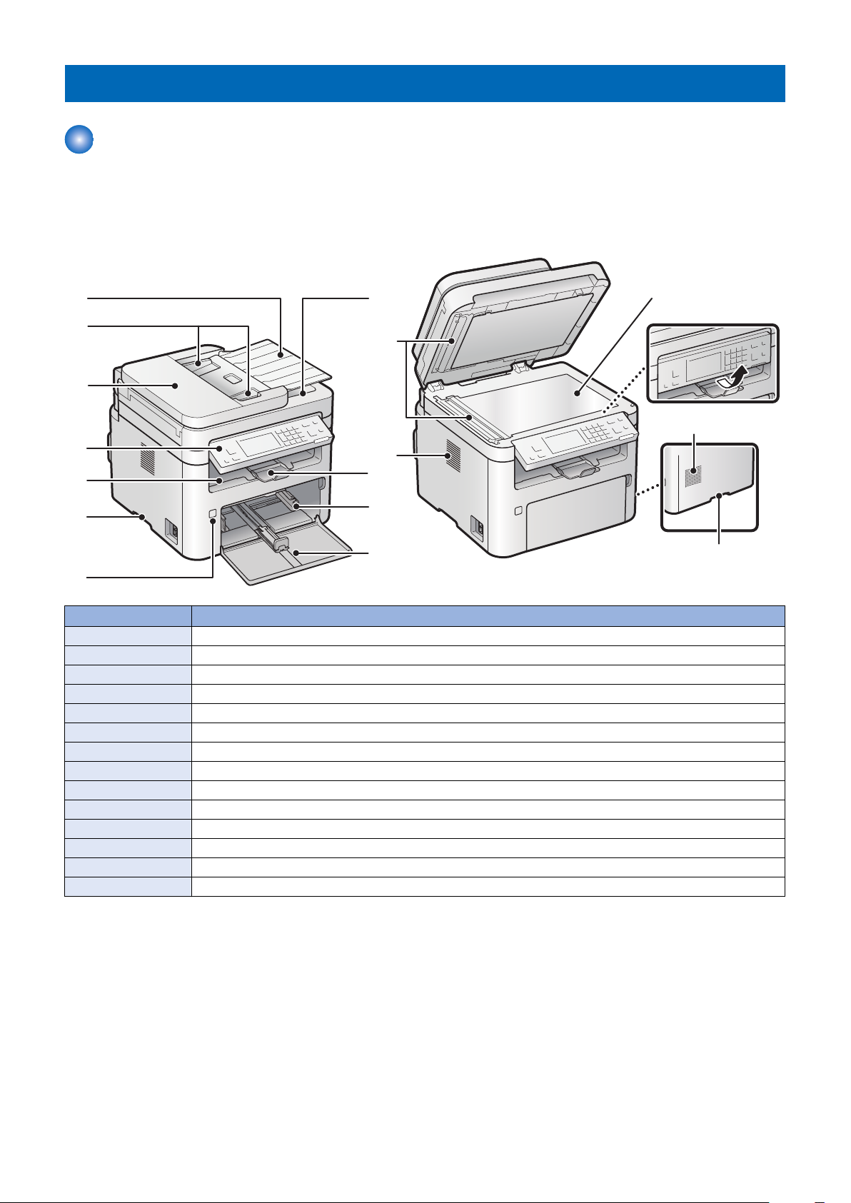
■ Front side of the machine
< ADF model >
1. Product Overview
No. Name
[1] Original Pickup Tray
[2] Original Guide
[3] Feeder Cover
[4] Control Panel
[5] Delivery Tray
[6] Handle for carrying
[7] Power Switch
[8] Document Delivery Tray
[9] Delivery Stopper
[10] Pickup Tray
[11] Front Cover
[12] Original Read Area
[13] Ventilation hole
[14] Copyboard Glass
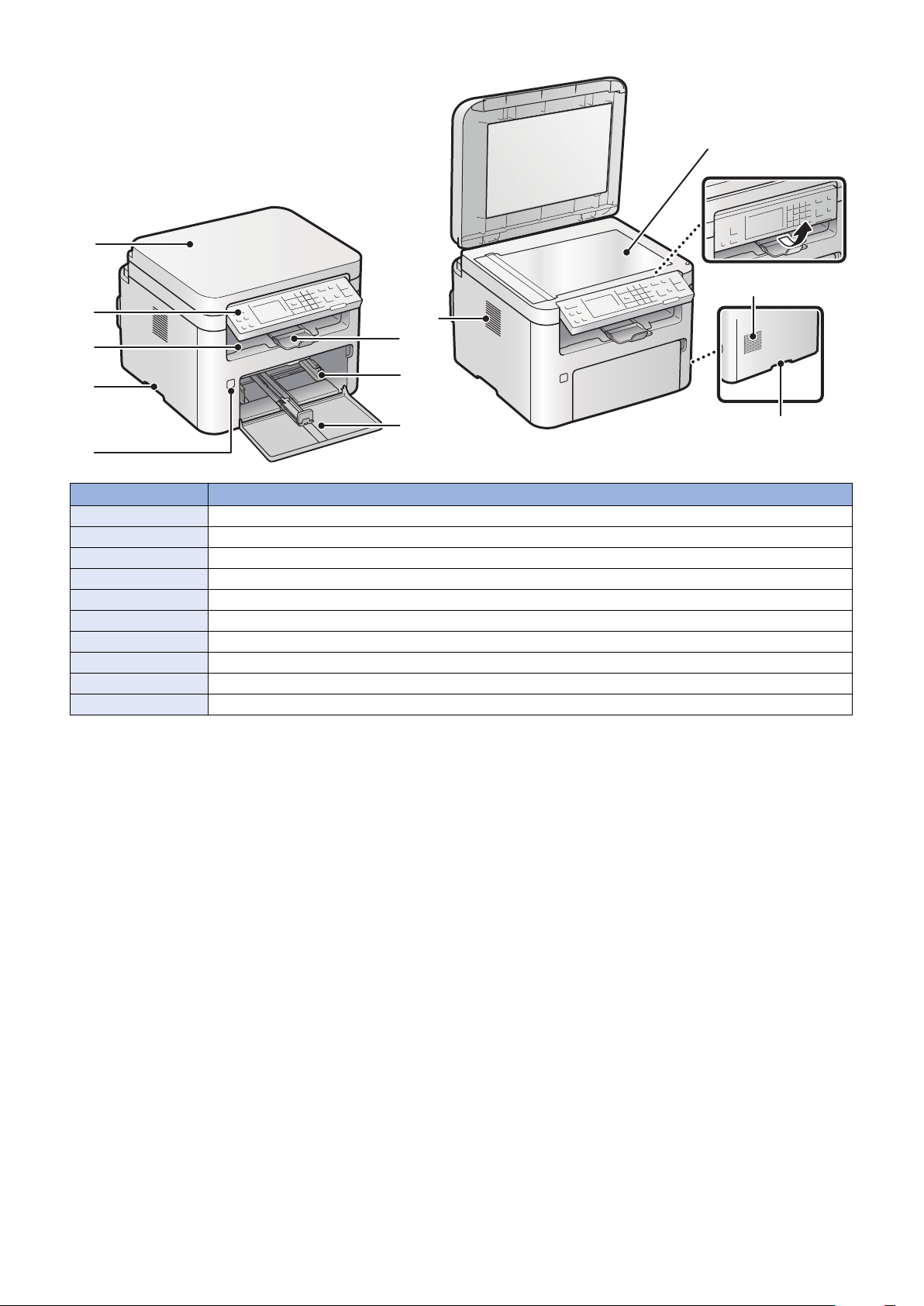
< Copyboard model >
14
[7]
[8]
[9]
[10]
[1]
[2]
[3]
[4]
[5]
[6]
[9]
[4]
1. Product Overview
No. Name
[1] Copyboard cover
[2] Control Panel
[3] Delivery Tray
[4] Handle for carrying
[5] Power Switch
[6] Delivery Stopper
[7] Pickup Tray
[8] Front Cover
[9] Ventilation hole
[10] Copyboard Glass
15
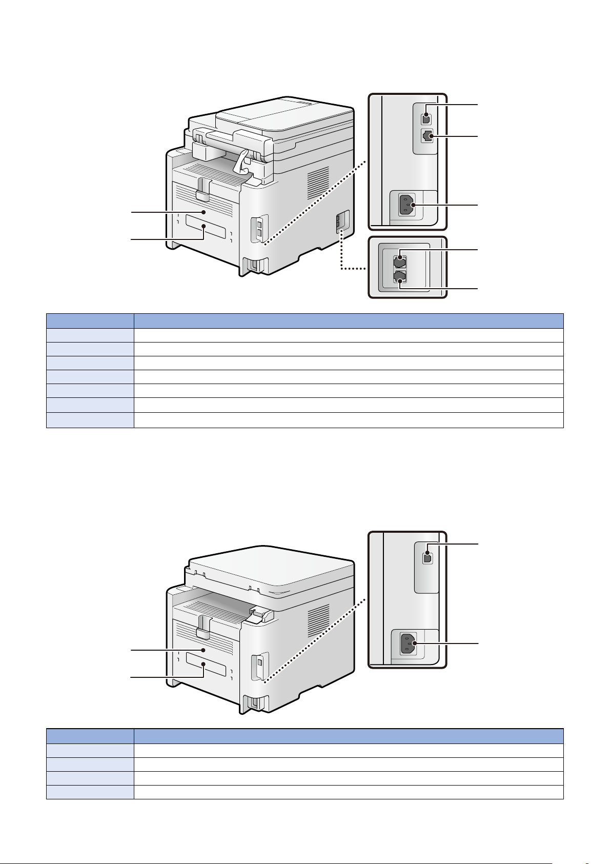
■ Rear side of the machine
[1]
[2]
[3]
[4]
[5]
[6]
[7]
[1]
[2]
[4]
[3]
< ADF model >
No. Name
[1] Rear Cover
[2] Rating name plate label
[3] USB port
[4] LAN Port
[5] Power Socket
[6]
[7]
*1
*1
External phone terminal
Phone line terminal
1. Product Overview
*1: FAX model only
< Copyboard model >
No. Name
[1] Rear Cover
[2] Rating name plate label
[3] USB port
[4] Power Socket
16
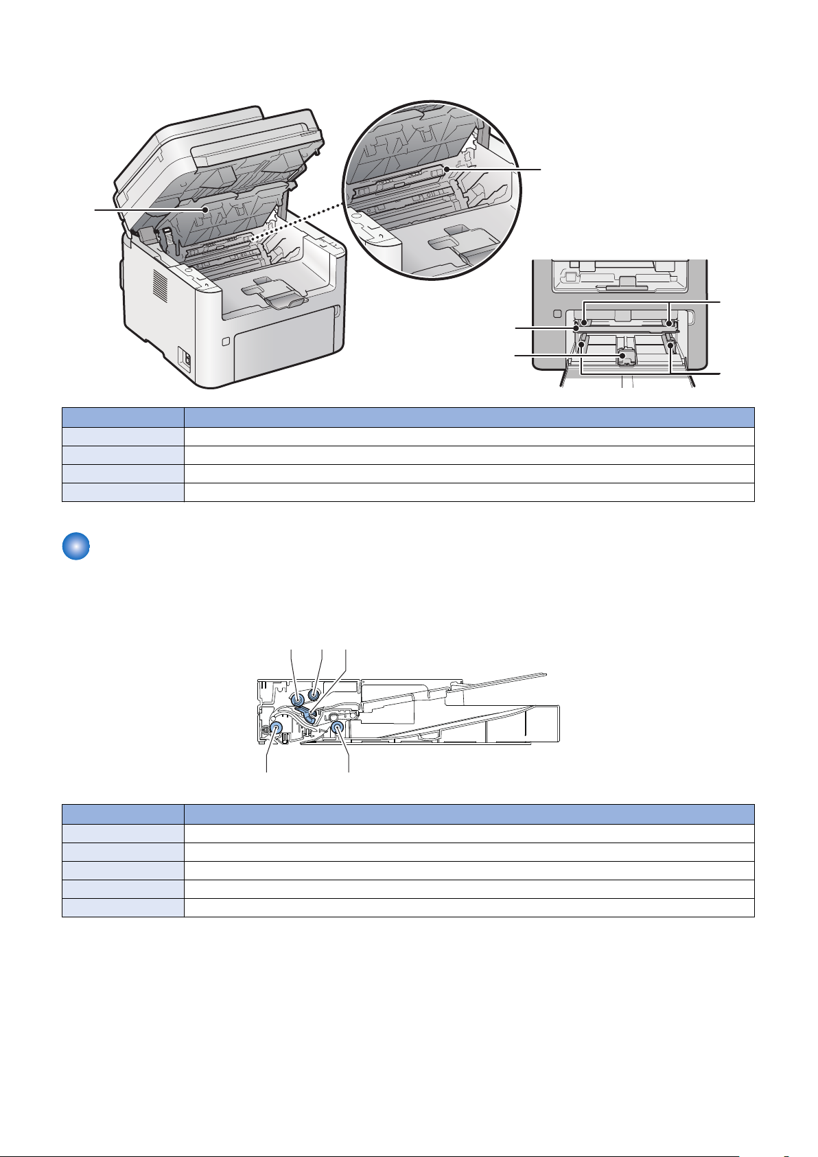
■ Inside of the host machine
3
[1]
[2]
[3]
[4]
[4]
[4]
[4]
[5]
[3][1] [2]
No. Name
[1] Toner Cover
[2] Delivery Guide
[3] Multi-purpose Tray
[4] Paper Guide
1. Product Overview
Cross Section View
■ DADF
No. Name
[1] Separation Roller
[2] Pickup Roller
[3] Separation Pad
[4] Delivery Roller
[5] Feed Roller
17
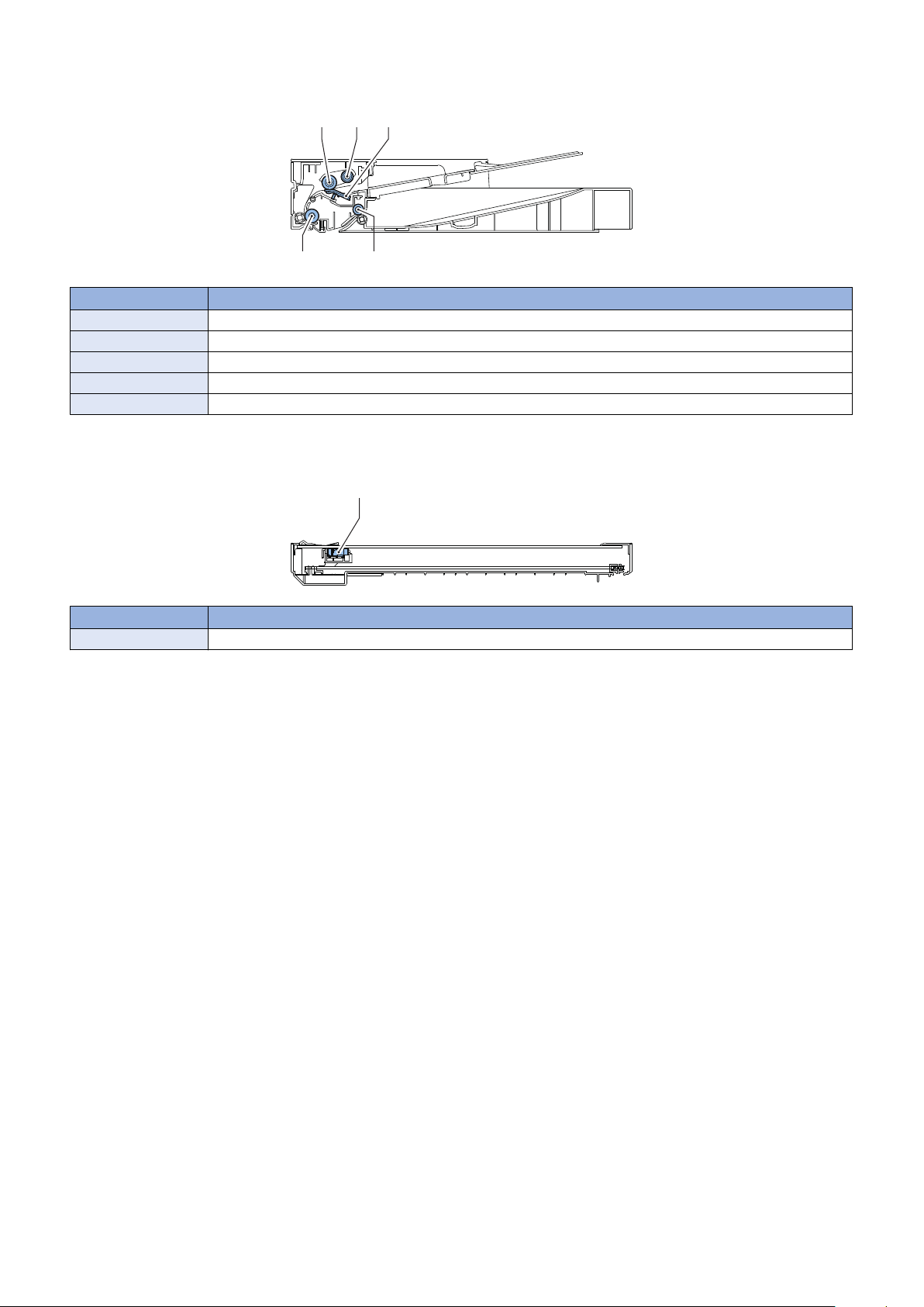
■ SADF
[4]
[5]
[3][1] [2]
[1]
No. Name
[1] Separation Roller
[2] Pickup Roller
[3] Separation Pad
[4] Delivery Roller
[5] Feed Roller
■ Reader
1. Product Overview
No. Name
[1] Contact Image Sensor
18
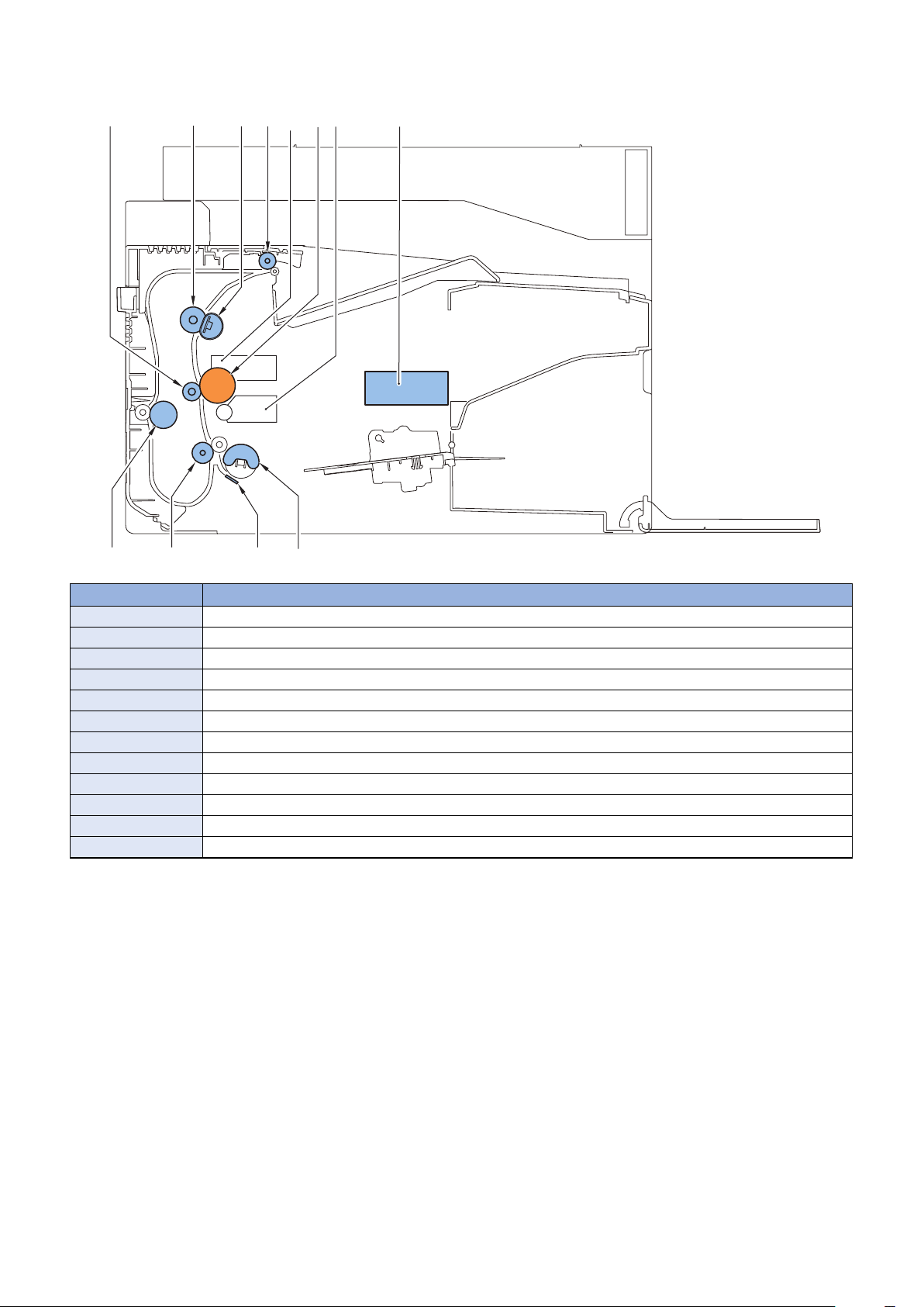
■ Printer
[8]
[10]
[11][12]
[9]
[3]
[1] [2]
[6]
[7]
[4] [5]
1. Product Overview
No. Name
[1] Transfer Roller
[2] Pressure Roller
[3] Fixing Film Unit
[4] Delivery Roller
[5] Drum Cartridge
[6] Photosensitive Drum
[7] Toner Cartridge
[8] Laser Scanner Unit
[9] Pickup Roller
[10] Separation Pad
[11] Feed Roller
[12] Duplex Roller
19

[5]
[1]
[10]
[15]
[6]
[14]
[7]
[9]
[3]
[13]
[8]
[4]
[12] [11]
[2]
1. Product Overview
Control Panel
■ Touch Panel Model
No. Key / LED name Function
[1] [Home] key Press to return to the home screen.
[2] Display Displays a message or operation status. Displays menu, selected item, texts, numbers and other
information when changing settings. Operation is performed by tapping the touch panel.
[3] [Reset] key Press to reset the settings (to change the settings of copy/scan/fax to standard mode).
[4] Numeric key Press to enter the number of copies, zoom value and the names and numbers of address book.
[5] [Stop] key Press to stop a job.
[6] [Energy Saver] key Press to manually enter/recover from energy saver mode.
• Off: In normal machine operation
• On (Green): In energy saving mode
[7] [Quiet mode] key Press to switch On / Off of the quiet mode.
• Off: In normal machine operation
• On (Green): In quiet mode
[8] Error LED Indicates Error status
• Off: No Error
• On (Orange): When an error that cannot be recovered by the user (service call) occurs
• Blinking (Orange): When an error that can be recovered by the user (such as paper jam, no
paper, etc.) occurs
* On status overrides Blinking status when the both occur simultaneously.
[9] Processing/Data LED Indicates Job status
• Off: No Job
• On (Green): Job waiting
• Blinking (Green): Job being executed
* On status overrides Blinking status when the both occur simultaneously.
[10] [Start] key Press to start a job.
[11] [Symbols] key Press to enter symbols.
[12] [Tone] key Use to send the tone signal from the dial line.
[13] [Clear] key Press to clear numbers such as number of copies, or text.
[14] [Back] key Press to return to the screen one layer above.
[15] [Status Monitor] key Press to check the status of printing, copying, scanning and outputting the Report.
20
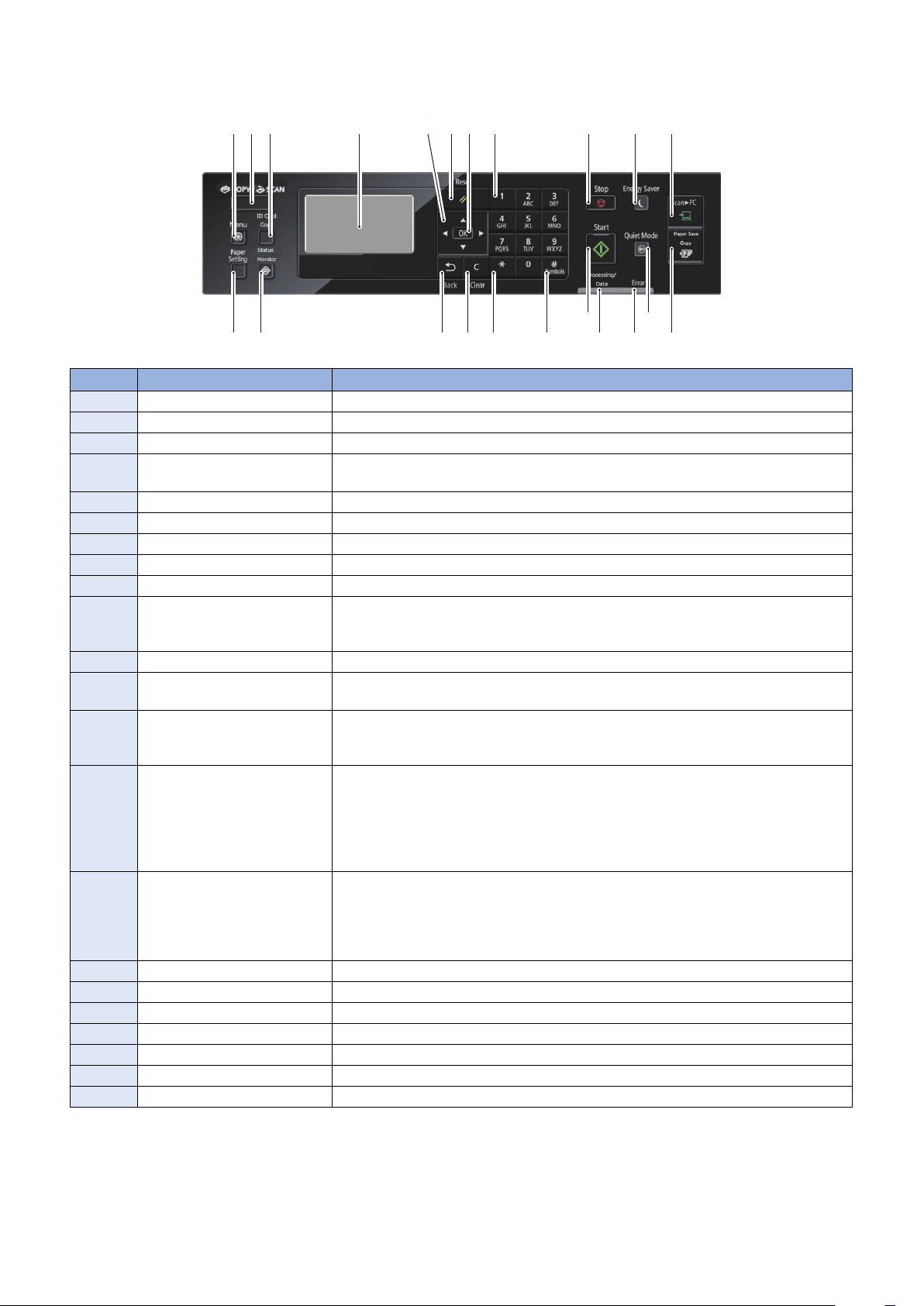
■ 5-line Control Panel Model
[20]
[2]
[19]
[1]
[8]
[3]
[18]
[22]
[17]
[21]
[9]
[16]
[6]
[10]
[5]
[13]
[7]
[11]
[12][15] [14]
[4]
No. Key / LED name Function
[1] [Menu] key Press to make various registrations and product settings.
[2] [Copy / Scan] key Press to switch Copy mode and Scan mode.
[3] [ID Card Copy] key Press to copy the front and back of a card onto the same side of a sheet of paper.
[4] Display Displays a message or operation status. Displays menu, selected item, texts, numbers
[5] Directional Keys Press to search setting items, increase / decrease input values, adjust setting values, etc.
[6] [Reset] key Press to reset the settings back to the standard mode settings.
[7] [OK] key Press to apply settings for functions and modes.
[8] Numeric keys Press to enter the number of copies, zoom values and text.
[9] [Stop] key Press to stop a job.
[10] [Energy Saver] key Press to manually enter/recover from energy saver mode.
[11] [Scan -> PC] key Press to store the scanned data to the registered PC.
[12] [Paper Save Copy] key Press to set 2 on 1 1-Sided > 2-Sided, 4 on 1 1-Sided > 2-Sided, 2 on 1 1-Sided > 1-sided,
[13] [Quiet mode] key Press to switch On / Off of the quiet mode.
[14] Error LED Indicates Error status
[15] Processing/Data LED Indicates Job status
[16] [Start] key Press to start a job.
[17] [Symbols] key Press to enter symbols.
[18] [*] key Use to send the tone signal from the dial line.
[19] [Clear] key Press to clear numbers such as number of copies, or text.
[20] [Back] key Press to return to the screen one layer above.
[21] [Status Monitor] key Press to check the status of printing, copying and outputting the Report.
[22] [Paper Settings] key Press to make paper settings.
1. Product Overview
and other information when changing settings.
• Off: In normal machine operation
• On (Green): In energy saving mode
4 on 1 1-Sided > 1-sided.
• Off: In normal machine operation
• On (Green): In quiet mode
• Off: No Error
• On (Orange): When an error that cannot be recovered by the user (service call) occurs
• Blinking (Orange): When an error that can be recovered by the user (such as paper
jam, no paper, etc.) occurs
* On status overrides Blinking status when the both occur simultaneously.
• Off: No Job
• On (Green): Job waiting
• Blinking (Green): Job being executed
* On status overrides Blinking status when the both occur simultaneously.
21

2
Technology
Basic Configuration.............................23
Document Exposure/Feeder System
.........................................................24
Controller System................................31
Laser Exposure System......................39
Image Formation System....................41
Fixing System......................................47
Pickup Feed System........................... 50
 Loading...