

Canon Fax-L240, Fax-L290, H12-2513, H12-2515, H12-2517 Service Reference Manual
...
HY8-90CY-000
JUNE 2002
COPYRIGHT
2002 CANON INC. CANON FAX-L240/L290 JUNE 2002 PRINTED IN JAPAN (IMPRIME AU JAPON)
REVISION 0
SERVICE REFERENCE
MANUAL
FAX-L240 H12-2513 230V EC
FAX-L240 H12-2514 230V UK
FAX-L240 H12-2515 230V GER
FAX-L240 H12-2517 230V FRN
FAX-L290 H12-2503 230V EC
FAX-L290 H12-2504 230V UK
FAX-L290 H12-2505 230V GER
FAX-L290 H12-2507 230V FRN
TELEPHONE 6 KIT H12-3823 230V EU
TELEPHONE 6 KIT H12-3824 230V UK
(EC/UK/GER/FRN)


1
I. PREFACE
This manual is based on the following manuals, and only includes differences between FAX-L200/
L280 and FAX-L240/L290.
HY8-10AQ-000 FAX-L200/L280 SERVICE MANUAL, Rev.0
HY8-30AM-000 FAX-L200/L280 PARTS CATALOG, Rev.0
HY8-80AP-000 FAX-L200/L280 CIRCUIT DIAGRAM, Rev.0
II. CONTENTS
CHAPTER 1 : POINTS OF DIFFERENCE FROM THE ORIGINAL MACHINE
This chapter explains the differences between this machine and the original one.
CHAPTER 2 : CIRCUIT DIAGRAM
This chapter contain the pages which are different from those in the Circuit Diagram
for FAX-L240/L290.

2
CHAPTER 1
POINTS OF DIFFERNECE
FROM THE ORIGINALMACHINE

3
1. Parts change
For details of any change in parts numbers, see the Par ts Catalog.
2. Specification change
Canges have been made to the electrical circuitry, and the functions of the NCU board have
been integrated with those of the SCNT board. In this Service Reference Manual, detailed
explanations of the electrical circuitry have been omitted (to respect the decision not to disclose
detailed information in technical documentation, e.g., on ICs).
Power consumption standby less than 3.5W / less than 500W (when operating)
Modulation method
G3 image signals ITU-T V.27ter, V.29, V .17, V.34
G3 procedure signals ITU-T V.21
Modem IC FM336plus
ADF capacity Max. 30 sheets (A4/Letter)
T ransmission/Reception FAX-L240: Approx. 256 pages
memory FAX-L290: Approx. 448 pages
Other Summer time added.
Detecting a Residual Cartr idge added.
Paper tray (ASF) FAX-L240 FAX-L290
Envelopes None Approx. 7 envelopes
Transparencies None 1 sheet
Note on Late Start: Do not change the settings of #1 SSSW SW28 bit2 and bit3.
If they are changed, a communication error might occur.

4
Interface specifications (FAX-L290)
interface USB only
Support software Windows 98/Me/2000/XP
Winsows 95/NT4.0 (Not support)
FAX-L290 Suite
USB I/F
Windows 95 not
supported
Windows 98 conditionally
supported*
Windows NT 4.0 not
supported
Windows 2000 conditionally
supported*
Windows Me conditionally
supported*
Windows XP conditionally
supported*
*: A USB connection applies to Windows XP/Me/2000 pre-install models and to
pre-install models upgraded to Windows XP/Me/2000 from Windows 98 or later.
Windows Drivers
Win98.Me LBP Printer Driver (USB suppor ted)
Win2000.XP LBP Printer Driver (USB supported)

5
3. Setting the Language and Country
When you connect the power cord to an AC outlet for the first time, you need to select the
language for the LCD display. For some countries, you also need to select the country where
you are using the FAX machine. The FAX machine automatically switches the selectable
settings and the default settings in the menus to suit the selected country.
Follow this procedure to set the language and country.
After connecting the power cord, the display changes from PLEASE WAIT to DISPLAY LANGUAGE.
Once you have selected the language and country, these setting menus will not appear next
time you connect the power cord.
Normally, the country selection window will appear when the user has selected a language.
A shift to the screen, howe ver, will not occur if the user has selected any of the f ollowing for #5
TYPE in service mode:
EUROPE2, POLAND, ASIA, SLOVENIA, SINGAPORE, CHINA, SAF, HONG KONG, N.Z,
AUSTRALIA, UK, GERMAN, ITALY, SWEDEN.

6
4. Setting the Summer Time
Some countries adopt the summer time system that shifts the clock time ahead or back according to the change in seasons. You can select if the time information in your FAX changes
to match your country summer time system and set the day and time when the summer time
begins and ends.
Operation at the Start of Summer Time
When the time selected for BEGIN DATE/TIME comes, the time stored by the machine is put
forward by 1 hour. Any delayed call falling whitin the affected time slot will immediately be
initiated when the time has come and the time has been put forward.
Operation at the End of Summer Time
When the time selected for END DATE/TIME comes, the time stored by the machine is put
back by 1 hour. Any delayed call falling whitin the affected time slot will immediately be initiated when the time has come and the time has been put back.
If exactly the same date/time is selected for BEGIN DATE/TIME and END DATE/TIME, the
time is put forward/back by 1 hour repeatedly year after year.
SUMMER TIME
SYSTEM SETTING
OFF
ON
BEGIN DATE/TIME
MONTH
WEEK
DAY
TIME
JANUARY
FEBRUARY
MARCH
APRIL
MAY
JULY
AUGUST
JUNE
SEPTEMBER
NOVEMBER
DECEMBER
OCTOBER
FIRST WEEK
SECOND WEEK
THIRD WEEK
LAST WEEK
FOURTH WEEK
SUNDAY
MONDAY
TUESDAY
WEDNESDAY
THURSDAY
SATURDAY
FRIDAY
END DATE/TIME
MONTH
WEEK
DAY
TIME
JANUARY
FEBRUARY
MARCH
APRIL
MAY
JULY
AUGUST
JUNE
SEPTEMBER
NOVEMBER
DECEMBER
OCTOBER
FIRST WEEK
SECOND WEEK
THIRD WEEK
LAST WEEK
FOURTH WEEK
SUNDAY
MONDAY
TUESDAY
WEDNESDAY
THURSDAY
SATURDAY
FRIDAY

7
#1 SSSW (service soft switch setting)
SW09 (service soft switch 09: communication result display function settings)
Bit Function 1 0
0 After normal end of communications, Display No display
communications results displayed
1 After communications ending in error, Display No display
communications results displayed
2 Not used
3 Not used
4 Not used
5 Not used
6 (New)Summer Time setting No display Display
7 Not used
[Bit 6]
If Display is selected, the items associated with the summer time function will be added to
the user data, enabling the user to make summer time settings.
8
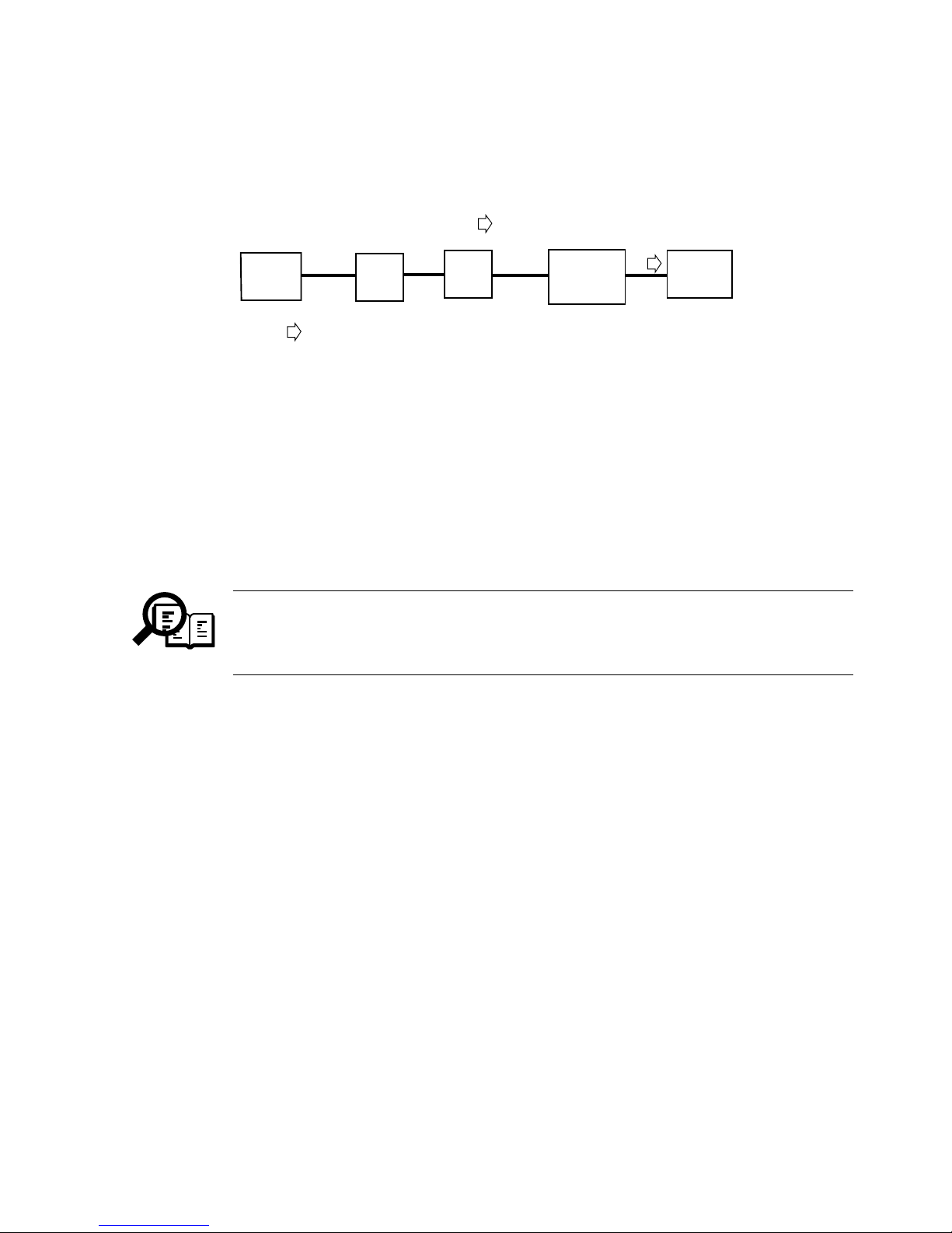
5. Detecting a Residual Cartridge
5.1 Out line
This mechanism is designed to automatically cammunicate (ECM) printer information,
e.g., cartridge replacement, printer number.
All Bits of the other machine’s DIS must be set to [1]; in other words, the presence of a single
[0] will cause the communication to end in error.
Bit 27 ECM: [0]=Not Provided, [1]=Provided
Bit 53 Binary File Transmission (BFT): [0]=Not Provided, [1]=Provided
Bit 99 Simple Phase C BFT Negotiations capability
: [0]=Not Provided, [1]=Provided
The communication will end normally if the other party returns MCF in
response to PPS-EOP. If, however, the other machine has a problem in
compatibility in relation to BFT, it will retur n FDM and the communication will
end in error.
NOTE
Printer information
Forwarding of data only
FAX-L240
FAX-L290
FAX
Win 2000
English
(BFT recive)
PSTN
Sever

9
5.2 Setting
The following items are available according to service mode settings:
ACTIVATION: Use it to ON/OFF the function.
PRODUCT NUMBER: Use it to register a product number (10 characters;upper case,
lower case; numerals; symbols).
SERIAL NUMBER: Use it to register a serial number (8 characters;upper case,
lower case; numerals; symbols).
CUSTOMER NUMBER: Use it to register a serial number (8 characters;upper case,
lower case; numerals; symbols).
SERVER PHONE NBR: Use it to register the telephone number of the contact
(25 characters; numerals; tone; pause; space).
CRITERION: Use it to store information about the cause of a call.
PAGES: number of prints (3700; 0-9999)
DAYS: number of days passed (30; 0-9999)
REPORT: Use it to generate a report of BFT registration data issued.
MANUAL TX: Use it to manually transmit BFT registration data.
CLEAR: Use it to clear all parameters set under Remote CRG.
#11 Remote CRG ACTIVATION
PRODUCT NUMBER
SERIAL NUMBER
CUSTOMER NUMBER
SERVER PHONE NBR
CRITERION
REPORT
CLEAR
MANUAL TX

10
5.3 Conditions for a Call
The function is enabled when ACTIVATION is set to ON, and the number of prints and the
date currently registered will server as its starting point.
Condition 1:
When as many prints as set for PAGES under CRITERION have been made.
Condition 2:
When the cartridge runs out of toner, requiring replacement.
Condition 3:
When as many days as set for DAYS under CRITERION have been made.
Condition 4:
When a service error related to the printer has occurred.
A log on the following is used for the execution of this function:
Total number of prints made by the printer.
Number of prints that previously satisfied condition 1.
Date/Number of prints that previously satisfied condition 3.
Executing ALL CLEAR or CLEAR for Remote CRG will also clear the log data.
Condition 1:
When the difference between the number of prints and the number of prints that previously
satisfied condition 1 reaches the registered number of prints, a BFT file will be prepared and
a call made.
If the registered number of days under condition 3 is [0], no call will be made
under this condition.
Condition 2:
When the cartridge runs out of toner to require replacement, a call will be made.
Thereafter, no call will be made under condition 2 until the cartridge has been replaced and
the power has been turned off and then on. However, if condition 2 occurs once again when
the power is turned on after replacement of the cart r idge, a call will be made.
NOTE
NOTE
11
Condition 3:
When as many days as set pass since the day on which condition 3 is satisfied and, in
addition, when 12 hours pass since the time at which ACTIVATION is set to ON, a call
will be made.
If the registered number of days under condition 3 is [0], no call will be made
under this condition.
Condition 4:
When a service error that is related to the printer occurs, call will be made.
Thereafter, no call will be made under condition 4 unless the error has been cleared and the
power has been turned off and then on once again. However, if condition 4 occurs when the
power is turned on once again after clearing of the error, a call will be made.
If a connection to the target machine fails when transmitting a BFT file, a shift
will be made to redialing mode. Redialing may be enabled/disabled, and the
number of redialing sessions depends on user settings.
NOTE
NOTE
12
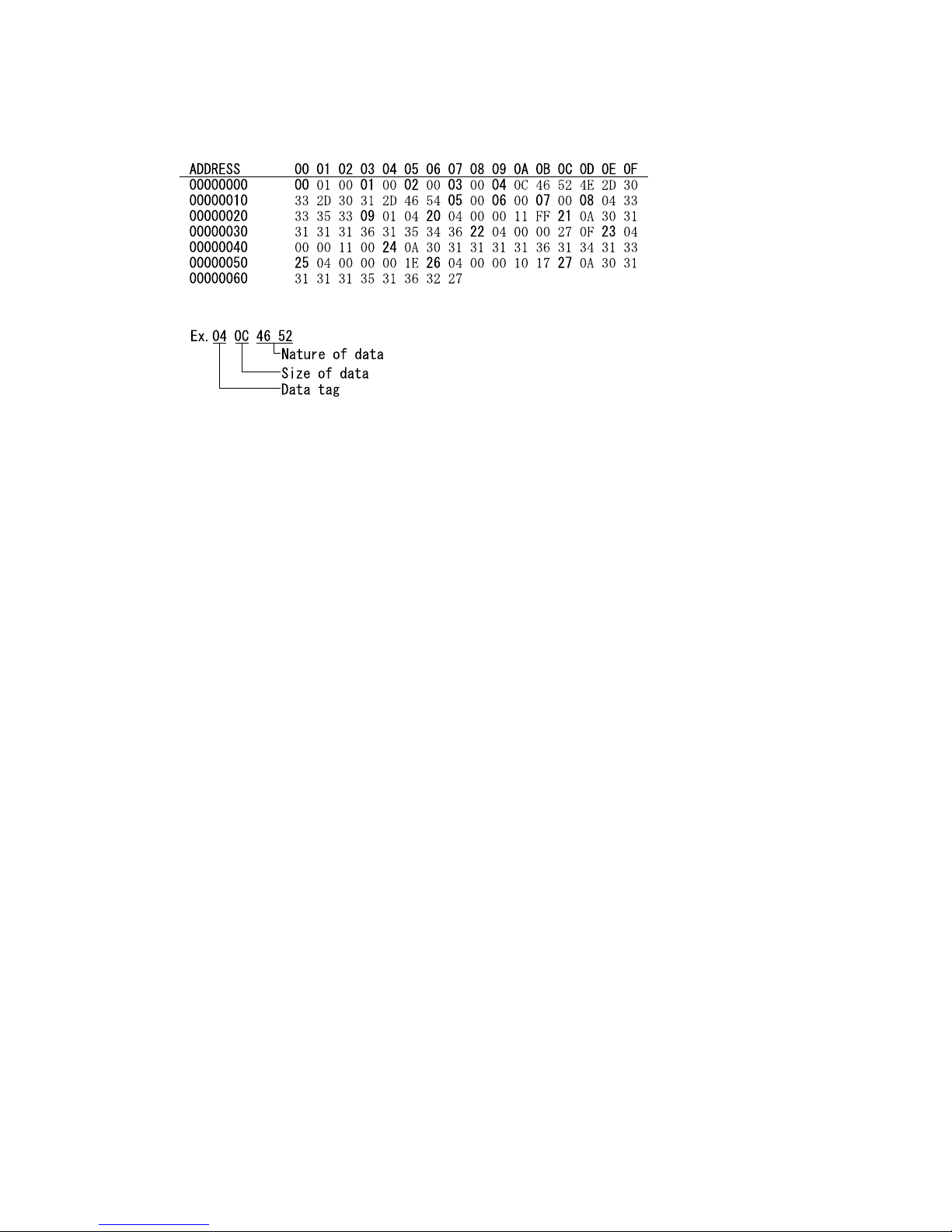
5.4 BFT File
A BFT file is constructed as follows:
00 call item 1: program version (fixed).
01 call item 2: product number (in ASCII).
02 call item 3: serial number (in ASCII).
03 call item 4: customer number (in ASCII).
04 call item 5: ROM version (in ASCII).
05 call item 6: FAX number (in ASCII).
06 call item 7: FAX name G3 (in ASCII).
07 call item 8: FAX name G4 (in ASCII).
08 call item 9: Server phone number (in ASCII).
09 call item 10: cause of call.
00: call condition 1.
01: call condition 2.
02: call condition 3.
03: call condition 4.
04: manual transmission.
20 call item 11: total number of prints (hexadecimal).
21 call item 12: date of transmission (in ASCII).
e.g., 2001 11 16 15:46 ---> 30 31 31 31 31 36 31 35 34 36
22 call item 13: number of prints set for PAGES under CRITERION (condition 1).
23 call item 14: number of prints when a call was made most recently under
condition 1.
24 call item 15: date on which a call was made most recently under condition 1.
25 call item 16: number of days set for DAYS under CRITERION (condition 3).
26 call item 17: number of prints when a call was made most recently under
condition 3.
27 call item 18: date on which a call was made most recently under condition 3.

13
5.5 Report
The following report may be generated in service mode:
ACTIVATION: Use it to ON/OFF the function.
PRODUCT NUMBER: Indicates the setting for PRODUCT NUMBER under
#11 Remote CRG.
CUSTOMER ACCOUNT Indicates the setting for CUSTOMER NUMBER under
NUMBER: #11 Remote CRG.
ROM VERSION: Indicates the version of the ROM.
FAX NUMBER: Indicates the setting for UNIT TELEPHONE as part of user
settings.
FAX NAME (G3): Indicates the setting for UNIT NAME as part of user settings.
FAX NAME (G4): None.
SERVER PHONE Indicates the setting for SERVER PHONE NUMBER for
NUMBER: #11 Remote CRG .
CRITERION: Indicates the setting of PAGES for CRITERION under.
PAGES: #11 Remote CRG
DAYS: #11 Remote CRG
14
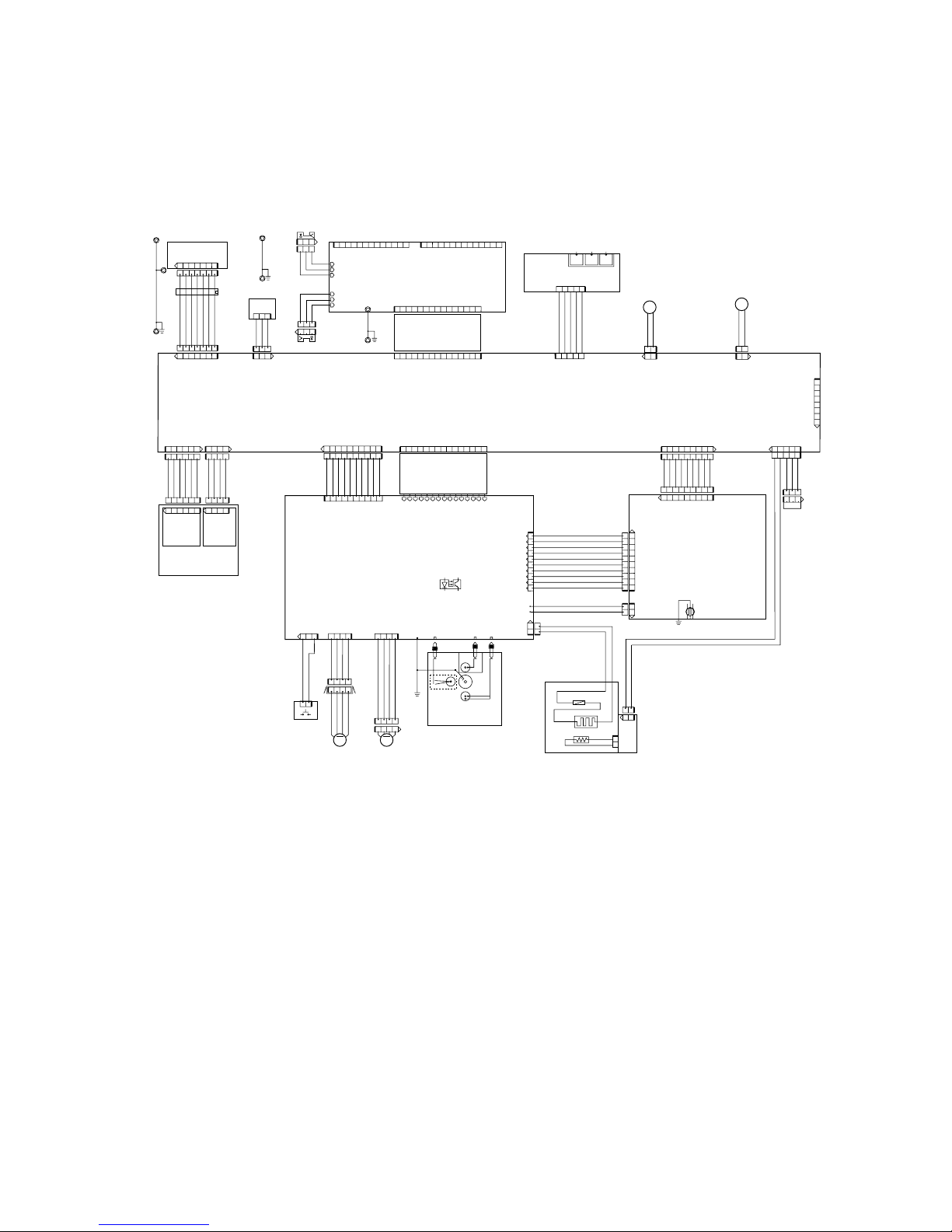
6. WIRING DIA GRAM
5.1 Wiring Diagram
Modular board
SCNT board
PCNT board
1
9
123456789
987654321
Power supply unit
INL101
10
1
12345678910
21
J102 J202
15
151
15 1
113
114
151
12345678910
12
12
12
123
123
321
321
J304J301J302J303
TONOR
CARTRIDGE
7654321
7654321
17
17
3
123
321
1
123456
1 6
21
12
4321
M
Document feed
MOTOR
1234
1234
M
Main MOTOR
1234
OPCNT board
DS
DES
TONOR
SENSOR
Upper Guide
Contact sensor
J12J2 J1
J8J4
J5
J2
J5
J1 J5
J601
J201
J1
INTER LOCK
FU
H701
TH701
221
1
21
J008M
Fixing ass'y
12
43
J2
Paper eject sensor
MEMBREN LCD
4321
J4
J3
J305
J402 J401
666
J1J2J3
J4
LINE
TEL
HAND
SET
54321
12
BZ
SPEAKER
12
J401
123
123
P S
Paper sensor edge
J14
21
J9
21
CL
Picup solenoid
54321
51
J102
21
21
21
19
16
123456141234
LASER unit
SCANNER
MOTOR
LASER SCANNER
unit
J801 802F
1234
1 4
J6
81
J102
USB (FAX-L290 only)
10
1
10987654321
J7
12345678910
4321
4321
13
15
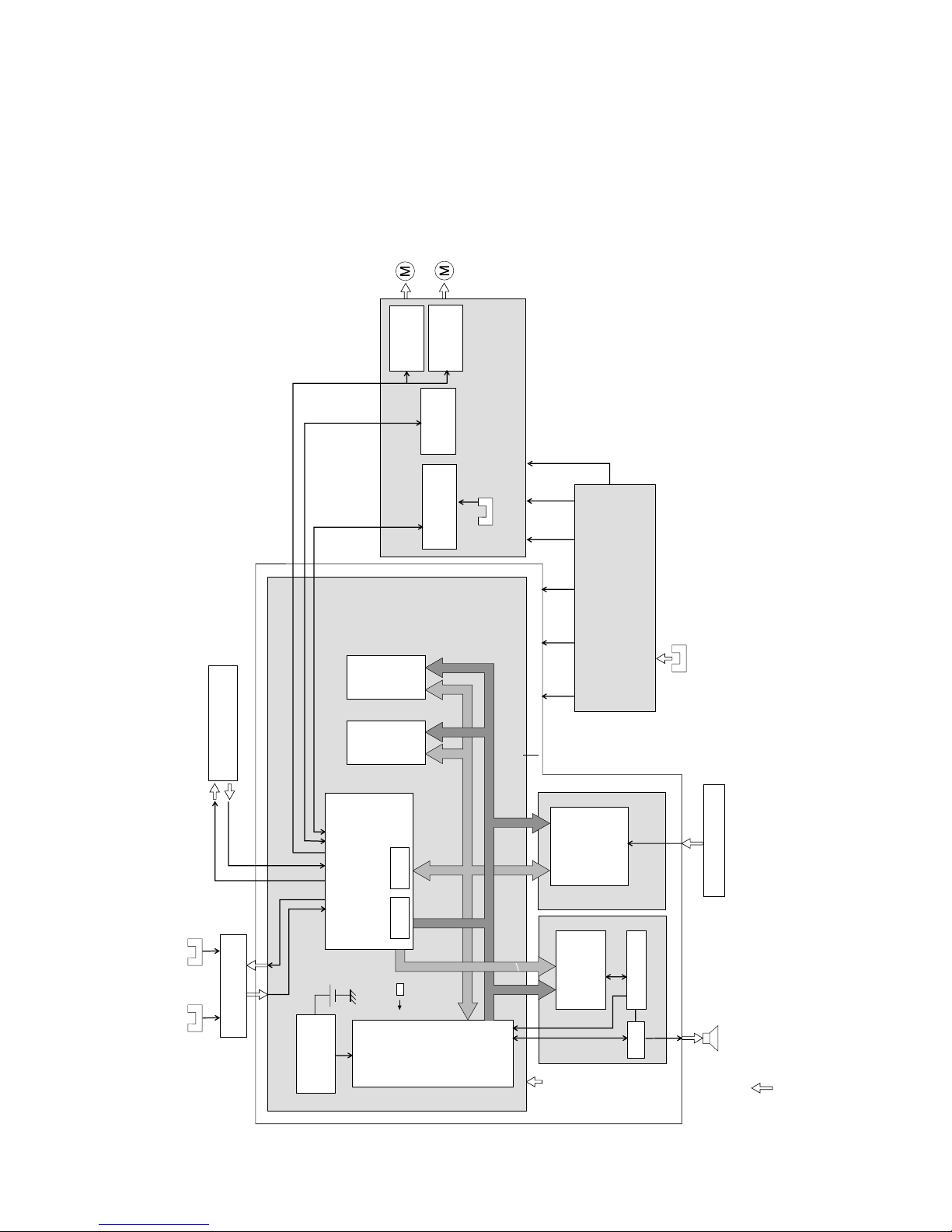
7. ELECTRIC CIRCUIT
5.1 Component Block Diagram
Driver
(IC402)
Driver
(IC401)
Main moter
Paper eject
sensor
d) PCNT board
Fixing
Controller
High-voltage
Controller
Dcument
feed motor
c)b)
MPU
(IC1)
Reset IC
(IC3)
System controller(1/2)
(IC8)
System
controller(2/2)
(IC8)
DRAM
64M bit
(IC4)
ROM
16M bit
(SOC1)
Address Bus, A24-SA0
Data Bus, AD16-SD0
MODEM
FM336PLUS
(IC401)
Amp.
Power supply unit
RTC SRAM
Paper edge
sensor
Toner
sensor
a) SCNT board
OPCNT board
Document
edge sensor
Document
sensor
Printer section
Contact sensor
Speaker
34.153MHz
+3.3V +5V +24V +24V +5V
a) System/Printer control section
b) Communication control section
c) Document scanning section
d) Fixing/high-voltage control section
Data Bus, MD7-MD0
+3.3V
NCU

16
7. Error codes and recovery methods
As for the descriptions of causes of and actions for error codes, only those items to which
changes have been made because of the use of different connector numbers are indicated.
#001 [TX] Paper jam
Cause: The document jammed in the fax machine.
Solutions: Remove the document and transmit/copy again.
Cause: The document width size or thickness does not meet the standards.
Solutions: Use a copy machine to copy the document to LTR or other standard size
Cause: Internal structure defect.
Solutions: (1) Check if the document sensor (DS) and document edge sensor (DES) are operating correctly
using the methods given in this chapter,5.1.6 Faculty tests, Test mode [6] Faculty test, [3]
Sensor tests.
(2) Check the actuators of the original sensor (DS) and the original edge sensor (DES) for discon-
nection.
(3) Check the document sensor (DS) and OPCNT board (J4) connections.
(4) Check the document edge sensor (DES) and OPCNT board (J3) connections.
(5) Check the SCNT board (J1) and OPCNT board (J2) connections.
(6) Make a copy,and make sure that the document read motor is operating corrctly.
(7) Check the document read motor and PCNT board (J402) connections.
(8) Check the SCNT board (J4) and PCNT board connections.
(9) Replace the document sensor (DS).
(10) Replace the document edge sensor (DES).
(11) Replace the OPCNT board.
(12) Replace the document read motor.
(13) Replace the SCNT board.
(14) Replace the PCNT board.

17
#003 [TX/RX] Copy page transmission time over
Cause: One page of the document was longer than 39.4 inches (1 meter) or transmission/copying took longer
than the regulated time (32 minutes).
Solutions: (1) Use a copy machine to copy the document onto serveral shorter page, then tranmit/copy.
(2) Raise the page timer value with Service Data #1 SSSW SW12.
Cause: Reception took longer than the regulated time (32 minutes).
Solutions: (1) Have the other party split the document over multiple pages and receive it that way.
(2) Contact the other party and check the cause.
(3) Raise the page timer value with Service Data #1 SSSW SW12.
Cause: Internal structure defect.
Solutions: (1) Check if the document sensor (DS) and document edge sensor (DES) are operating correctly
using the methods given in this chapter,5.1.6 Faculty tests, Test mode [6] Faculty test, [3]
Sensor tests.
(2) Check the document sensor (DS) and OPCNT board (J4) connections.
(3) Check the document edge sensor (DES) and OPCNT board (J3) connections.
(4) Check the SCNT board (J1) and OPCNT board (J2) connections.
(5) Make a copy,and make sure that the document read motor is operating corrctly.
(6) Check the document read motor and PCNT board (J402) connections.
(7) Check the SCNT board (J4) and PCNT board connections.
(8) Replace the document sensor (DS).
(9) Replace the document edge sensor (DES).
(10) Replace the OPCNT board.
(11) Replace the document read motor.
(12) Replace the SCNT board.
(13) Replace the PCNT board.
#009 [RX] Recording paper jam or out of paper
Cause: The recording paper jammed.
Solutions: Clear the recording paper jam.
Cause: There is no recording paper.
Solutions: Load recording paper.
Cause: Internal structure defect.
Solutions: (1) Check the actuators of the recording paper edge sensor and the recording paper delivery sensor
for damage and deformation.
(2) Check the connection of the main motor and the PCNT board (J401).
(3) Check the connection of the power unit (J205) and the recording paper sensor.
(4) Check the connection of the PCNT board and the SCNT board (J4); check the connection of the
power unit (J202) and the PCNT board (J101); then, check the connection of the power supply
unit (J201) and the SCNT board (J8).
(5) Replace the sensor.
(6) Replace the main motor.
(7) Replace the PCNT board.
(8) Replace the SCNT board.
(9) Replace the power supply unit.

18
##322 [RX] Fixing heater temperature abnormality
Cause: Internal unit defect.
Solutions: (1) Check the connections between the fixing ass’y and the PCNT board (J102) and between the
fixing ass’y and the SCNT board (J14).
(2) Check the connection between the PCNT board (J1) and the power supply unit (J202).
(3) Check the resistance between connector pins of the fixing ass’y.
J206-12 and J206-13: 436 to 301 kΩ (at 25°C)
J102-1 and J102-2: 25.1 to 28.8 Ω (at 25°C)
If either resistance is incorrect, replace the fixing ass’y.
(4) Replace the PCNT board.
(5) Replace the power supply unit.
(6) Replace the SCNT board.
##324 [RX] Printer section scanner motor rotation rate abnormal
Cause: Internal unit defect (Incorrect scanner motor speed)
Solutions: (1) Check the connection between the LASER/scanner section (J802) and the SCNT board (J6).
(2) Replace the LASER/scanner section.
(3) Replace the SCNT board.

19
General errors
• The unit does not turn on. (Evaluation criteria: Look at the actual unit.)
(1) Check the power cord connection.
(2) Check the connection between the PCNT board (J1) and power supply unit (J202).
(3) Check the connection between the SCNT board (J8) and power supply unit (J201).
(4) Check the connection between the SCNT board (J4) and PCNT board.
(5) Check the power supply unit’s fuse (F101/F102).
(6) Replace the power supply unit.
• Abnormal display. (Applicable test mode: Operation panel test)
Nothing is displayed.
(1) Check the connection between the OPCNT board (J2) and SCNT board (J1).
(2) Check the connection between the LCD unit and OPCNT board (J5).
(3) Replace the LCD unit.
(4) Replace the OPCNT board.
(5) Replace the SCNT board.
Part of the LCD panel does not display anything.
(1) Check for LCD problems with the test mode.
(2) Check the connection between the OPCNT board (J2) and SCNT board (J1).
(3) Check the connection between the LCD unit and OPCNT board (J5).
(4) Replace the LCD unit.
(5) Replace the OPCNT board.
(6) Replace the SCNT board.
• The buttons do not work. (Applicable test mode: Operation panel test)
(1) If the test mode can be used, check for faulty buttons.
(2) Check the connection between the OPCNT board (J2) and SCNT board (J1).
(3) Check the connection between the Membren sheet and OPCNT board (J1).
(4) Replace the Membren sheet.
(5) Replace the OPCNT board.
(6) Replace the SCNT board.
• No sound from the speaker
(1) Check the connection of the speaker and SCNT board (J401).
(2) Replace the speaker.
(3) Replace the SCNT board.

20
Printing problems
• Faulty printing (Evaluation criteria: Test print is faulty.)
• The paper is not fed correctly. (Evaluation criteria: Look at the actual unit.)
The main motor does not run.
(1) Check the connection between the main motor and the PCNT board (J401).
(2) Check the main motor’s resistance. 8.1 ~ 12.54 Ω/1 phase is normal. (Fig. 4-4)
(3) Replace the main motor.
(4) Replace the PCNT board.
(5) Replace the SCNT board.
The paper is not picked up from the auto sheet feeder.
(1) Check whether the recommended paper is used.
(2) Check whether more than 100 sheets of paper have been loaded in the auto sheet feeder.
(3) Check whether the paper has been loaded into the sheet feeder correctly.
(4) Check the connection between the paper pickup solenoid and the SCNT boatd (J9).
(5) Replace the paper pickup solenoid.
(6) Clean the separation pad.
(7) Replace the separation pad.
(8) Replace the separation pad spring or the lifting spring.
(9) Replace the SCNT board.
The paper skews.
(1) Check whether the recommended paper is used.
(2) Check whether more than 100 sheets of paper have been loaded in the sheet feeder.
(3) Check whether the paper has been loaded into the sheet feeder correctly.
(4) Check whether dust or paper debris have built up inside the auto sheet feeder.
(5) Check whether the paper pickup roller, or any other rollers, are damaged or scratched.
• The printing operation is abnormal.
The unit indicates there is a paper jam when there is no paper jam.
(1) Check the connection from the paper edge sensor to the SCNT board (J214).
(2) Check whether the paper edge sensor and actuator and the paper eject sensor actuator are in their correct positions.
(3) In test mode check whether the paper edge sensor and the paper eject sensor are operating correctly.
(4) Replace the SCNT board.
1
4
Main motor connector
1-2 : 8.1~12.54Ω
3-4 : 8.1~12.54Ω
Main motor
1
4
To document feed motor
Document feed motor connector
1-2 : 13.95~25.68Ω
3-4 : 13.95~25.68Ω

21
Scanning problems
• Faulty scanning (Evaluation criteria: Test print is good, b ut the copied image is poor.)
• The document is not fed.
The document feed motor does not run. (Evaluation criteria: Check it visually.)
(1) Check the connection between the document feed motor and the PCNT board (J402).
(2) Check the document feed motor’s resistance. 13.95 ~ 25.68 W/1 phase is normal. (Fig. 4-4)
(3) Replace the document feed motor.
(4) Replace the PCNT board.
(5) Replace the SCNT board.
The document slips against the rollers. (Evaluation criteria: Check it visually. Stretched copy image.)
(1) See page 4-4 and clean the document reading section.
(2) Replace the reading section’s rollers.
The document does not separate. (Evaluation criteria: Check it visually.)
(1) Check whether the document feed motor is driving all the rollers. (Check for any damaged gears or foreign matter
stuck inside.)
(2) Check whether the document feed lever is set to manual document feed.
(3) See page 4-4 and clean the separation roller and separation guide.
(4) Replace the separation roller and separation guide.
The scanner unit’s sensors are defective (Evaluation criteria: The placed document or transpor ted
document is not detected.)
(1) Check for any faulty sensors while executing the copying operation and test mode.
(2) Check the connection between the OPCNT board (J2) and the SCNT board (J1).
(3) Replace OPCNT board.
(4) Replace the SCNT board.
 Loading...