

Canon FY8-13FW-000DADF-A1, DADF-A1 Service Manual
DADF-A1
REVSION 0
DEC. 1998
COPYRIGHT © 1998 CANON INC. CANON DADF-A1 REV.0 DEC. 1998 PRINTED IN JAPAN (IMPRIME AU JAPON)
FY8-13FW-000

IMPORTANT
THIS DOCUMENTATION IS PUBLISHED BY CANON INC., JAPAN, TO SERVE AS A SOURCE
OF REFERENCE FOR WORK IN THE FIELD.
SPECIFICATIONS AND OTHER INFORMATION CONTAINED HEREIN MAY VARY SLIGHTLY
FROM ACTUAL MACHINE VALUES OR THOSE FOUND IN ADVERTISING AND OTHER
PRINTED MA TTER.
ANY QUESTIONS REGARDING INFORMA TION CONTAINED HEREIN SHOULD BE DIRECTED
TO THE COPIER SERVICE DEPARTMENT OF THE SALES COMPA NY.
THIS DOCUMENT ATION IS INTENDED FOR ALL SALES AREAS , AND MA Y CONTAIN INFORMA TION NOT APPLICABLE T O CERTAIN AREAS.
COPYRIGHT © 1998 CANON INC.
Printed in Japan
Imprimé au Japon
Use of this manual should be strictly supervised to avoid disclosure of confidential
information.
Prepared by
OFFICE IMAGING PRODUCTS TECHNICAL SUPPORT DEPARTMENT 1
OFFICE IMAGING PRODUCTS TECHNICAL SUPPORT DIVISION
CANON INC.
5-1, Hakusan, 7-chome, Toride-City , Ibaraki-Pref ., 302-8501, Japan
COPYRIGHT © 1998 CANON INC. CANON DADF-A1 REV.0 DEC. 1998 PRINTED IN JAPAN (IMPRIME AU JAPON)

INTRODUCTION
This Service Manual provides information needed to service the DADF in the field. This Service
Manual consists of the following chapters:
Chapter 1 “General Description” introduces the DADF’s features and specifications, and
shows how to operate it.
Chapter 2 “Basic Operation” introduces the ADAF’s mechanical and electrical systems; it also
explains the principles used in these systems and the timing at which they are
operated with reference to the ADAF’s electrical circuitry.
Chapter 3 “Mechanical System” explains the ADAF’s mechanical construction and how its
parts may be disassembled/assembled and adjusted.
Chapter 4 “Maintenance and Servicing” provides tables of periodically replaced parts and
consumables/durables and scheduled servicing charts.
Chapter 5 “Troubleshooting” provides tables of maintenance/inspection, standards/
adjustments, and problem identification (image fault/malfunction).
Appendix contains a general timing chart and general circuit diagrams.
The descriptions in this Service Manual are subject to change without notice for product
improvement or other purposes, and major changes will be communicated in the form of Service
Information bulletins.
All service persons are expected to have a good understanding of the contents of this Service
Manual and all relevant Service Information bulletins, and be able to identify and isolate faults in the
machine.
COPYRIGHT © 1998 CANON INC. CANON DADF-A1 REV. 0 DEC. 1998 PRINTED IN JAPAN (IMPRIME AU JAPON)
i

CONTENTS
CHAPTER 1 GENERAL DESCRIPTION
I. FEATURES ................................1-1
II. SPECIFICATIONS ......................1-2
A. DADF-A1...............................1-2
III. NAMES OF PARTS ....................1-4
A. External View.........................1-4
B. Cross Section ........................1-4
CHAPTER 2 BASIC OPERATION
I. BASIC CONSTRUCTION ...........2-1
A. Outline of the Electrical Circuitry.
...............................................2-1
B. Communication with the Copier
...............................................2-2
C. Inputs to the D ADF Controller
PCB.......................................2-3
D . Outputs to the DADF Controller
PCB.......................................2-5
II. BASIC OPERATION ................... 2-6
A. Outline ................................... 2-6
B. Operation............................... 2-7
C. Detecting Originals.............. 2-12
D. Picking Up Originals............ 2-17
IV. OPERATION...............................1-5
A. Original Set Indicator .............1-5
B. Warning and Actions..............1-5
C. Routine Maintenance by the
User.......................................1-6
E. Reversal .............................. 2-25
F. Reduced Page Composition
.............................................2-27
G. Delivery ............................... 2-34
H. Stamping Function...............2-40
I. Controlling the Pick-Up Motor
.............................................2-43
J. Controlling the Belt Motor
.............................................2-45
K. Detecting Original Jams
.............................................2-47
L. Improper Placement of
Originals ..............................2-50
III. POWRE SUPPLY ..................... 2-53
A. Outline .................................2-53
COPYRIGHT © 1998 CANON INC. CANON DADF-A1 REV.0 DEC. 1998 PRINTED IN JAPAN (IMPRIME AU JAPON)
iii

CHAPTER 3 MECHANICAL SYSTEM
I. BASIC CONSTRUCITON........... 3-1
A. External Covers .....................3-1
B. Switches ................................3-3
C. Adjusting the DADF Height
...............................................3-5
II. DRIVE SYSTEM ........................ 3-6
A. Removing the Pick-Up
Motor Unit ..............................3-6
B. Removing the Feeder Motor Unit
...............................................3-6
C. Belt Motor ..............................3-7
D. Removing the Clutch Unit
...............................................3-9
E. Delivery Motor .....................3-10
III. FEEDING SYSTEM .................. 3-11
A. Pick-Up Roller ..................... 3-11
B. Removing the Separation
Belt Unit............................... 3-12
C. Feeding Roller Unit ............. 3-12
D. Registration Roller ............... 3-14
E. Delivery/Resersing Roller
............................................. 3-16
F. Delivery Roller Unit
(bottom Pick-up Mode).........3-20
G. Delviery Roller Unit
(top Pick-up Mode)...............3-20
H. Reversing Guide ..................3-22
I. Stopper Plate Solenoid ........3-24
J. Positioning the Paper Retaining
Plate Solenoid (SL2) ...........3-24
K. Positioning the Paper Deflecting
Solenoid (SL3) .....................3-26
L. Stamp Solenoid ...................3-26
M. Feeding Belt ........................3-28
IV. CLEANING ............................... 3-30
A. Belt Assembly......................3-30
B. Sensors ...............................3-30
C. Separation Flapper..............3-33
D. Separation Guide .................3-33
V. FEEDING .................................3-34
A. Pick-Up Drive Assembly...... 3-34
B. Right Delivery Drive
Assembly............................. 3-34
CHAPTER 4 MAINTENANCE AND SERVICING
I. PERIODICALLY REPLACED
PARTS ........................................ 4-1
II. CONSUMABLES AND
DURABLES ................................4-1
III. SCHEDULED SERVICING
CHART ....................................... 4-2
iv
COPYRIGHT © 1998 CANON INC. CANON DADF-A1 REV.0 DEC. 1998 PRINTED IN JAPAN (IMPRIME AU JAPON)

CHAPTER 5 TROUBLESHOOTING
I. STANDARDS AND
ADJUSTMENTS ........................ 5-1
A. Mechanical System ...............5-1
B. Electrical System .................5-17
II. TROUBLESHOOTING ..............5-20
A. Troubleshooting
Malfunctions ........................5-20
III. ARRAIGMENT OF THE ELECTRI-
CAL PARTS .............................. 5-24
A. Motors, Solenoids, and
Sensors ...............................5-24
APPENDIX
A. GENERAL TIMING CHART ...... A-1
B. NAMES AND ABBREVIATIONS OF
SIGNALS................................... A-4
C. DADF-A1 GENERAL CIRCUIT
DIAGRAM.................................. A-5
B. PCB .....................................5-26
IV. VARIABLE RESISTORS, LIGHT-
EMITTING DIODES, AND CHECK
PINS BY PCB...........................5-27
A. DADF Controller PCB .......... 5-27
B. Indicator PCB ......................5-29
C. DIP Switch Functions ..........5-30
V. SELF DIAGNOSIS....................5-32
A. DADF Self Diagnosis .......... 5-32
D. DADF CONTROLLER CIRCUIT
DIAGRAM.................................. A-6
E. DISPLAY BOARD .................... A-13
F. SPECIAL TOOLS..................... A-14
G. SOLVENTS AND OILS............ A-15
COPYRIGHT © 1998 CANON INC. CANON DADF-A1 REV.0 DEC. 1998 PRINTED IN JAPAN (IMPRIME AU JAPON)
v

CHAPTER 1
GENERAL DESCRIPTION
I. FEATURES .................................1-1
II. SPECIFICATIONS.......................1-2
A. DADF-A1 ...................................1-2
III. NAMES OF PARTS..................... 1-4
A. External View.............................1-4
B. Cross Section ............................1-4
COPYRIGHT © 1998 CANON INC. CANON DADF-A1 REV.0 DEC. 1998 PRINTED IN JAPAN (IMPRIME AU JAPON)
IV. OPERATION................................1-5
A. Original Set Indicator .................1-5
B. Warnings and Actions................1-5
C. Routine Maintenance
by the User.................................1-6

CHAPTER 1 GENERAL DESCRIPITON
I. FEATURES
1. Two Types of Pick-Up Mode
Top pick-up: Pick-up starts with the top page.
Bottom pick-up: Pick-up starts with the bottom page.
2. Stamp Marking
The machine can mark originals with a stamp to indicate that they have been processed for fax
transmission.
3. Original Size Identification
The machine can identify the size of an original in terms of its length (feeding direction) and
width for communication to its host copier.
COPYRIGHT © 1998 CANON INC. CANON DADF-A1 REV.0 DEC. 1998 PRINTED IN JAPAN (IMPRIME AU JAPON)
1-1

CHAPTER 1 GENERAL DESCRIPITON
II. SPECIFICATIONS
A. DADF-A1
Item
Original pick-up
Original placement 1
Original placement 2
Original pick-up
Original type
Original size
Original tray
Delivery tray
Original processing
mode
Original size
identification
Residual original
detection
Continuous feeding
Size mix
Communication with
copier
Power supply
Maximum power
consumption
Weight
Dimensions (mm)
Serial No.
Operating conditions
Temperature Humidity
Specifications
Circulating, auto duplexing pick-up method
Face up
Center reference
Top pick-up
Bottom pick-up
Sheet (50 to 105 g/m2), single-sided sheet,
double-sided sheet
A5/STMT to A3/279×432 mm (11"×17")
If small size, 50 sheets, 5.5 mm high max.
(A5, B5, B5R, A4, A4R, STMT, LTR, LTRR)
If large size, 25 sheets (B4, A3, LGL,
279×432 mm (11"×17")
If small size, 50 sheets (A5, B5, B5R, A4,
A4R, STMT, LTR, LTRR)
If large size, 25 sheets (B4, A3, LGL,
279×432 mm (11"×17")
Single-sided, double-sided, reduce image
composition
Length (feeding direction) and width
Possible in conjunction with the host copier.
Possible
Possible
Possible
IPC 2
24 VDC (from the host copier)
170 W or less
14.1 kg (approx.)
684 (W) × 527 (D) × 161 (H)
AB ZLZ xxxxx
INCH/A ZNE xxxxx
A ZNF xxxxx
INCH/AB ZNG xxxxx
Same as the host copier.
Remarks
See p.2-17.
No extra length original.
Paper of 80 g/m2 or less.
Paper of 80 g/m2 or less.
Paper of 80 g/m2 or less.
Paper of 80 g/m2 or less.
For fax processing only.
Of the same width only.
For fax processing only.
Not including the
delivery tray.
Not including the
delivery tray.
1-2
The above specifications are subject to change for product improvement.
Table 1-201
COPYRIGHT © 1998 CANON INC. CANON DADF-A1 REV.0 DEC. 1998 PRINTED IN JAPAN (IMPRIME AU JAPON)

CHAPTER 1 GENERAL DESCRIPITON
Note:
The following must not be used as originals:
• A transparency or paper with an opacity of 80% or less.
• A carbon-backed sheet.
• A sheet with paste-ups or binding.
• A sheet with a cut-off, hole, or tear.
• A sheet with a clip or glue.
• A sheet with curling, wrinkling, or creasing.
Caution:
Do not feed the same original more than 30 times to protect against damage.
COPYRIGHT © 1998 CANON INC. CANON DADF-A1 REV.0 DEC. 1998 PRINTED IN JAPAN (IMPRIME AU JAPON)
1-3

CHAPTER 1 GENERAL DESCRIPITON
III. NAMES OF PARTS
A. External View
[1] [2] [3] [4] [5] [6] [7] [8]
Figure 1-301
[1] Upper cover
[2] Side guide
[3] Re-circulating guide
[4] Original Set indicator
[5] Original tray
[6] Sub tray
[7] Body cover
[8] Original delivery tray
B. Cross Section
[1] [2] [3] [4] [5] [6] [7] [8] [9] [10]
[1] Delivery/reversing roller
[2] Paper deflecting plate
[3] Feeding roller
[4] Separation belt
[5] Separation flapper
[6] Pre-separation guide
[16] [15] [14] [13] [12] [11]
Figure 1-302
[7] Delivery/pick-up roller
[8] Paper retaining plate
[9] Pick-up roller
[10] Delivery roller
[11] Feeding belt link roller
[12] Retaining rolls
[13] Feeding belt
[14] Paper stopper plate
[15] Feeding belt drive roller
[16] Registration roller
1-4
COPYRIGHT © 1998 CANON INC. CANON DADF-A1 REV.0 DEC. 1998 PRINTED IN JAPAN (IMPRIME AU JAPON)
CHAPTER 1 GENERAL DESCRIPITON
IV. OPERATION
A. Original Set Indicator
The Original Set indicator turns on when
an original is placed on the original tray, and
flashes when an original jams.
A4/B5
A3/B4
Figure 1-401
Operation
1) If the original is B5R or larger or is A5 in
feeding length, open the original sub tray.
2) Set the side guide to suit the size of the
original.
B. Warnings and Actions
If the Original Set indicator flashes while
an original is being fed, suspect a jam and
perform the following:
1) Remove the originals from the original
tray.
2) Open the upper cover, and remove the jam.
Then, open the DADF to reset the
warning. (If any original is on the
copyboard glass, remove it.)
Caution:
If the jam is in the copier, the copier will
run jam recovery mode and will
automatically set the originals. Do not
open the DADF to reset.
3) Set the originals in correct order, and set
the stack in the DADF.
Reference:
The side guide lock must be removed if
the width of the original is larger than 297
mm (A4/A3). For details, see 3. “Side
Guide Lock” on p. 3-3.
3) Place the originals with the first page on
top.
4) As needed, set the appropriate copying
mode on the copier.
5) Press the copier’s Copy Start key.
COPYRIGHT © 1998 CANON INC. CANON DADF-A1 REV.0 DEC. 1998 PRINTED IN JAPAN (IMPRIME AU JAPON)
1-5
CHAPTER 1 GENERAL DESCRIPITON
C. Routine Maintenance by the User
Instruct the user to clean the following at least once a week:
1. Copyboard Glass
Wipe it with a cloth moistened with water or alcohol; then, dry-wipe it.
2. Feeding Belt
Wipe it with water or alcohol.
3. Other Parts
Clean all other parts of the DADF (if soiled) using a solution of mild detergent; then, dry-wipe
them to remove any residue.
4. Feeding Belt and Feeding Roller
Execute cleaning mode in the copier’s user mode.
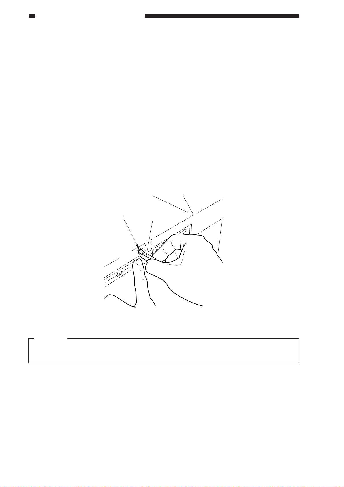
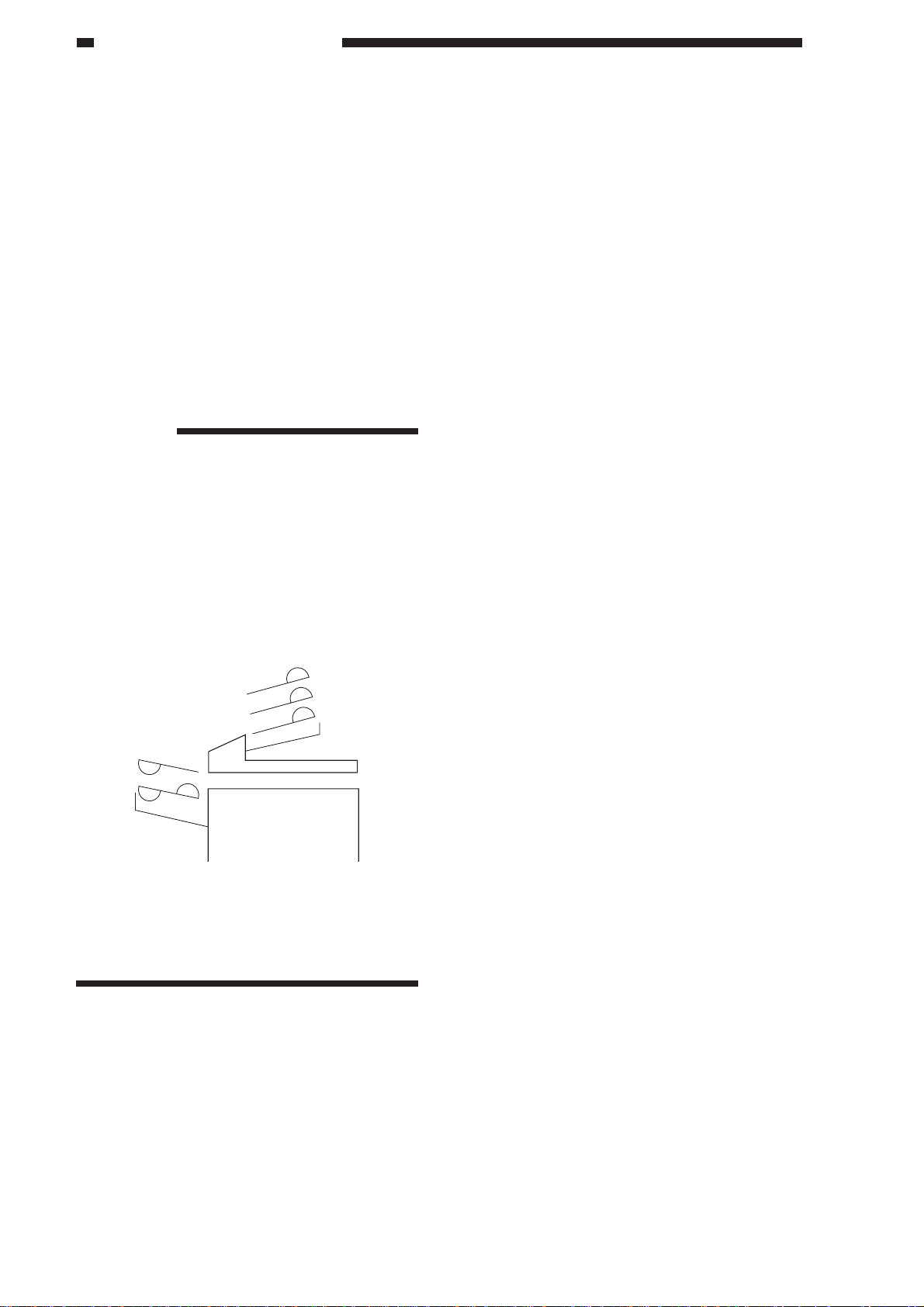
5. Stamp
If markings start to be fuzzy, replace the stamp using tweezers.
Stamp
Tweezers
Figure 1-402
Caution:
Do not touch the stamp face. If your skin has come into contact with its ink, be sure to wash it
with water immediately.
1-6
COPYRIGHT © 1998 CANON INC. CANON DADF-A1 REV.0 DEC. 1998 PRINTED IN JAPAN (IMPRIME AU JAPON)

CHAPTER 2
BASIC OPERATION
I. BASIC CONSTRUCTION ........... 2-1
A. Outline of the Electrical
Circuitry......................................2-1
B. Communication with the Copier.2-2
C. Inputs to the DADF
Controller PCB ........................... 2-3
D . Outputs to the D ADF Controller PCB
...................................................2-5
II. BASIC OPERATION.................... 2-6
A. Outline .......................................2-6
B. Operation ...................................2-7
C. Detecting Originals ..................2-12
COPYRIGHT © 1998 CANON INC. CANON DADF-A1 REV.0 DEC. 1998 PRINTED IN JAPAN (IMPRIME AU JAPON)
D. Picking Up Originals ................ 2-17
E. Reversal ..................................2-25
F. Reduced Page Composition.... 2-27
G. Delivery ....................................2-34
H. Stamping Function ...................2-40
I. Controlling the Pick-Up Motor ..2-43
J. Controlling the Belt Motor ........2-45
K. Detecting Original Jams...........2-47
L. Improper Placement of
Originals ..................................2-50
III. POWRE SUPPLY ...................... 2-53
A. Outline ..................................... 2-53
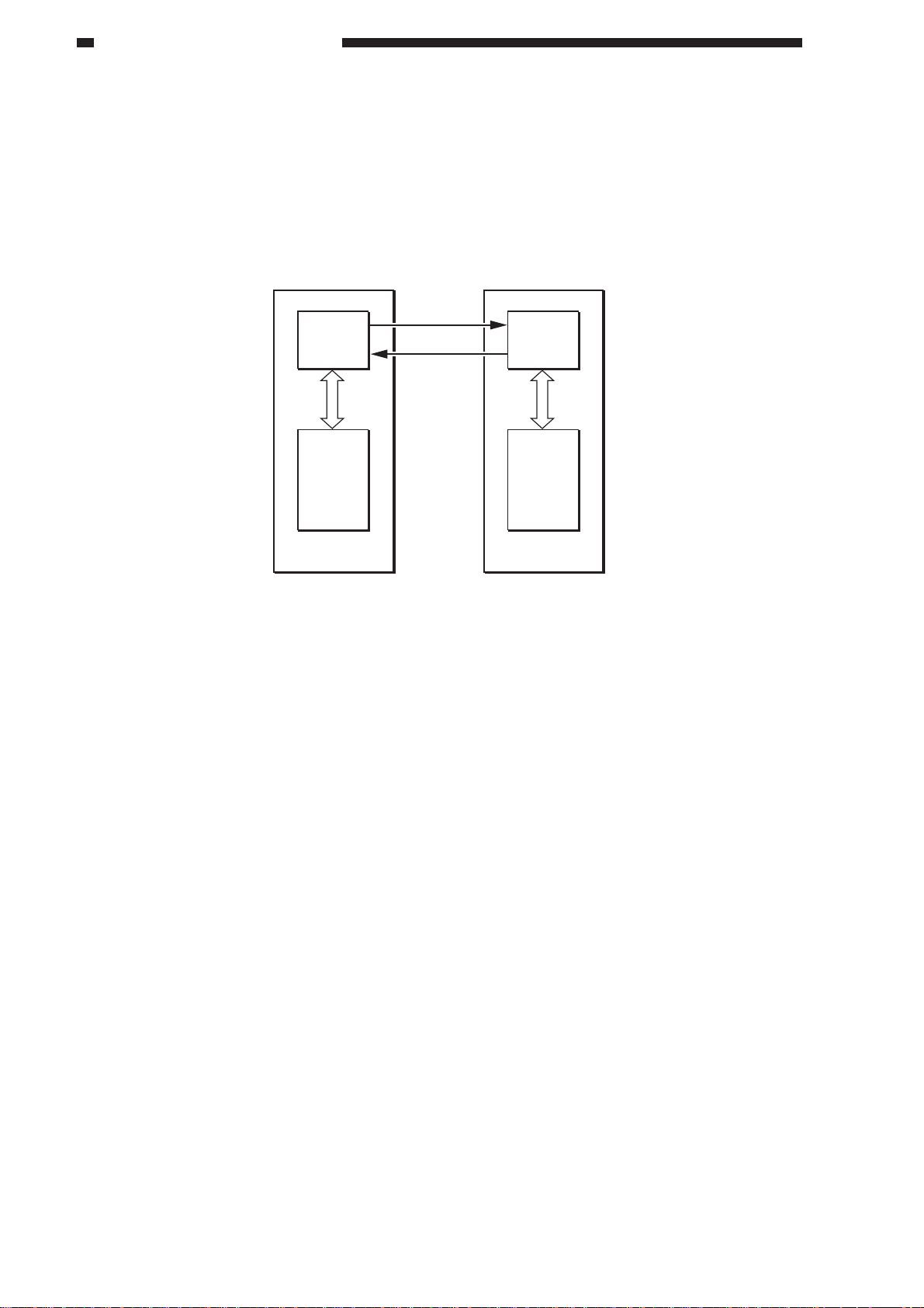
CHAPTER 2 BASIC OPERATION
I. BASIC CONSTRUCTION
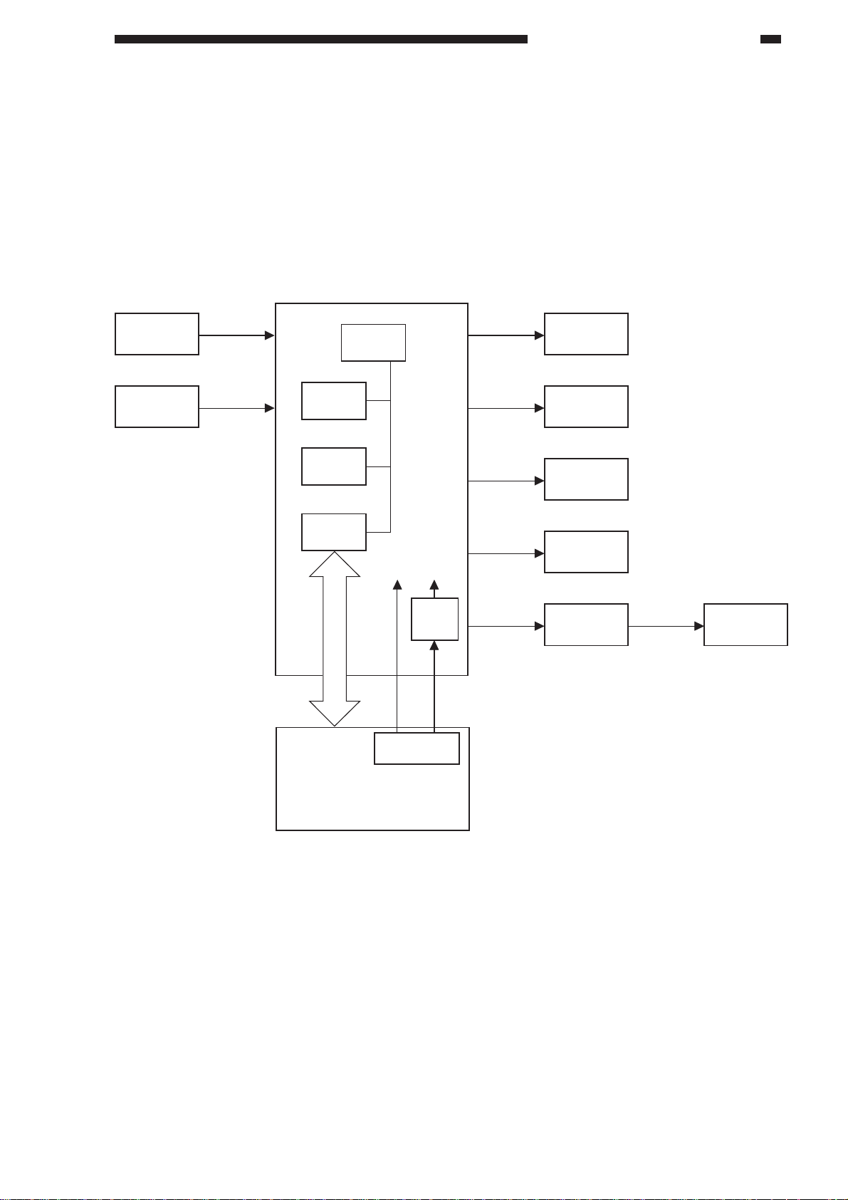
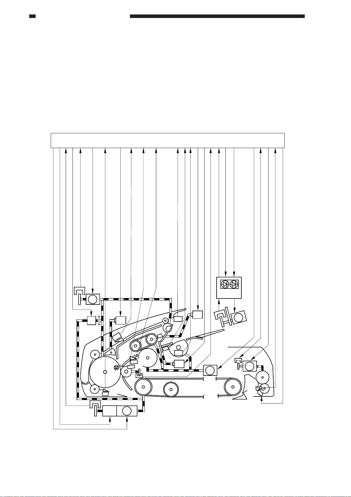
A. Outline of the Electrical Circuitry
The machine’s electrical mechanisms are controlled by the DADF controller PCB. A
microprocessor (CPU) is used on the DADF controller PCB, and the microprocessor reads the input
signals from the sensors and the copier and generates signals used to drive DC loads (motors,
solenoids) at such times as programmed in advance.
DADF controller PCB
Sensor
V ariable
resistor
CPU
(Q1)
ROM
(Q2)
RAM
(Q4)
Communication
IC(Q3)
24V
Power supply
5 VDC
power
supply
J2-1
circuit
5V
J1-6
Motor
Solenoid
Clutch
Brake
Indicator
LED PCB
Motor
Copierk
Figure 2-101
COPYRIGHT © 1998 CANON INC. CANON DADF-A1 REV.0 DEC. 1998 PRINTED IN JAPAN (IMPRIME AU JAPON)
2-1
CHAPTER 2 BASIC OPERATION
B. Communication with the Copier
The operation modes selected on the copier are communicated to the machine in an IPC
communication method. Likewise, the operation states of the machine are communicated to the
copier in an IPC communication.
If an error occurs in the IPC communication, the copier’s self diagnosis function turns on to
indicate “E400” or “E712” on its control panel.
RSOUT
Communication
IC
RSIN
Communication
IC
CPUCPU
Copier DADF
Figure 2-102
2-2
COPYRIGHT © 1998 CANON INC. CANON DADF-A1 REV.0 DEC. 1998 PRINTED IN JAPAN (IMPRIME AU JAPON)
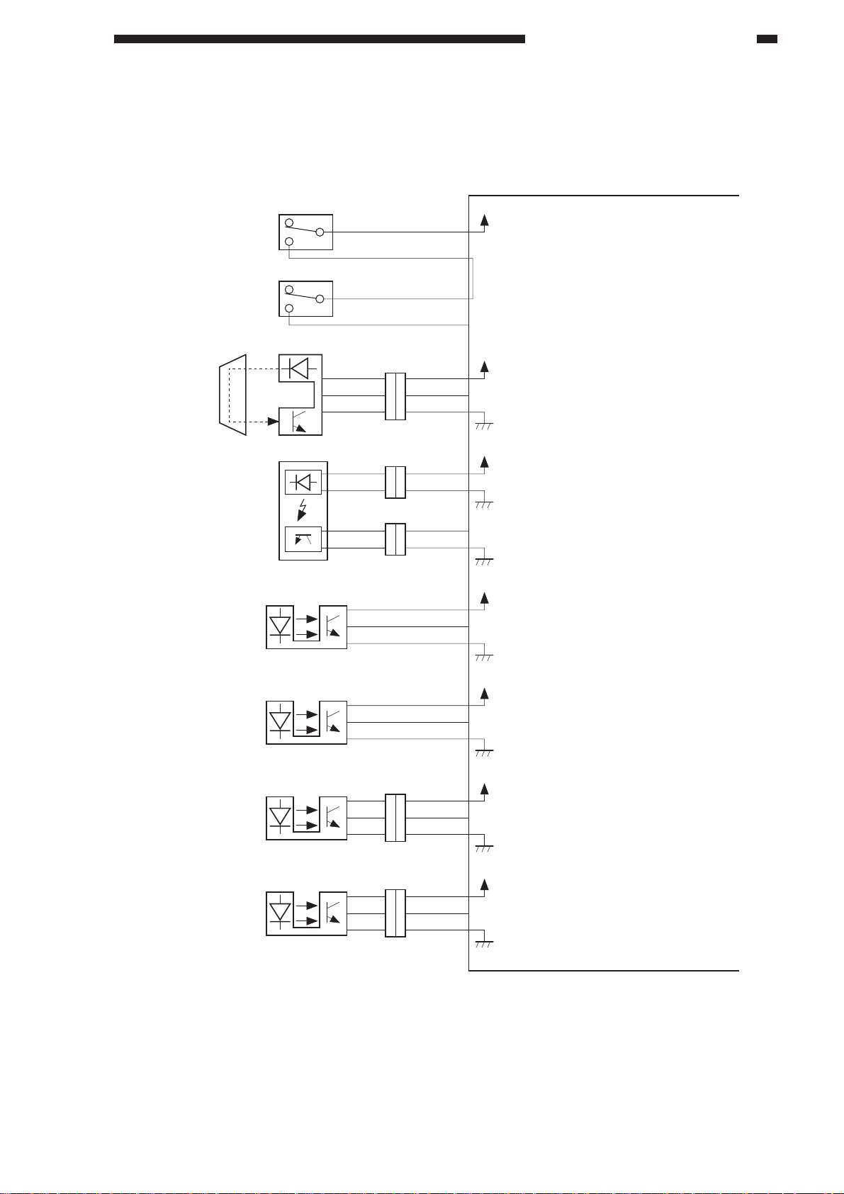
C. Inputs to the DADF Controller PCB
1. Inputs to the DADF Controller PCB (1/2)
DADF switch
MS1
Upper cover switch
MS2
Original tray
paper sensor
S1
COM J2-3
NO
COM
NO
J203
-4
J31-2
J5-7
-8
-9
RFC
UPCC1
EMPS
CHAPTER 2 BASIC OPERATION
DADF controller PCB
+24V
When the RDF is open, '0'.
When the upper cover is open, '0'.
+5V
When an original blocks the sensor, '1'.
Registration
paper sensor
Upper cover
sensor
Pick-up roller sensor
Delivery sensor 1
LED3
S3
S4
S5
S6
-1
-2
+5V
ENTS
+5V
CVRSW
+5V
DCTS
+5V
EJTS1
When an original blocks the sensor, '1'.
When the upper cover is open, '0'.
(The light-blocking plate is at the sensor.)
When the pick-u roller is
at the home position, '1'.
(The light-blocking plate is at the sensor.)
When an original is detected, '1'.
(The light-blocking plate is at the sensor.)
J205
2
J212
2
3
1
2
3
1
2
J207
3
1
1
3
2
2
3
41
1
21
3
1
2
J9-B10
-B9
-B12
-B11
J9-B6
-B8
-B7
J5-3
J9-A1
-A3
-A2
Pick-up sensor
S7
J208
3
1
1
3
2
2
3
1
2
J9-A4
-A6
-A5
+5V
SPRS
When an original is detected, '1'.
(The light-blocking plate is at the sensor.)
Figure 2-103
COPYRIGHT © 1998 CANON INC. CANON DADF-A1 REV.0 DEC. 1998 PRINTED IN JAPAN (IMPRIME AU JAPON)
2-3
CHAPTER 2 BASIC OPERATION
2. Inputs to the DADF Controller PCB (2/2)
DADF controller PCB
Reversal sensor S8
Feeder motor
S9
clock sensor
Belt motor
S10
clock sensor
Registration roller
S11
clock sensor
Delivery sensor 2 S12
J209
3
1
2
1
2
3
1
2
3
1
2
3
3
1
2
1
3
2
1
3
2
J219
3
1
2
3
1
2
J9-A7
-A9
-A8
J9-A12
-A11
-A10
J9-B5
-B4
-B3
J5-4
-5
-6
J14-4
-6
-5
+5V
TURNS
+5V
FCLK
+5V
BCLK1
+5V
RCLK
+5V
EJTS2
When an original is detected, '1'.
(When the light-blocking plate is
at the sensor.)
While the feeder motor is rotating,
alternates '1' and '0'.
While the feeder motor is rotating,
alternates '1' and '0'.
While the feeder motor is rotating,
alternates '1' and '0'.
When an original is detected, '1'.
(When the light-blocking plate is
at the sensor.)
Delivery motor
clock sensor
Re-circulation
sensor
Original width
detecting VR
S13
Display PCB
S14
J219
1
3
2
2
3
1
J101-3
-2
-1
J218
3
2
1
J14-3
4
-2
5
-1
6
J8-3
-2
-1
1
J8-7
2
-8
3
-9
+5V
ECLK
+5V
RSS
+5V
WIDTH
While the delivery motor is rotating,
alternates '1' and '0'.
When the re-circulation bar is set
on the top original, '1'.
Detects the width of the original
stacked on the original tray.
2-4
COPYRIGHT © 1998 CANON INC. CANON DADF-A1 REV.0 DEC. 1998 PRINTED IN JAPAN (IMPRIME AU JAPON)
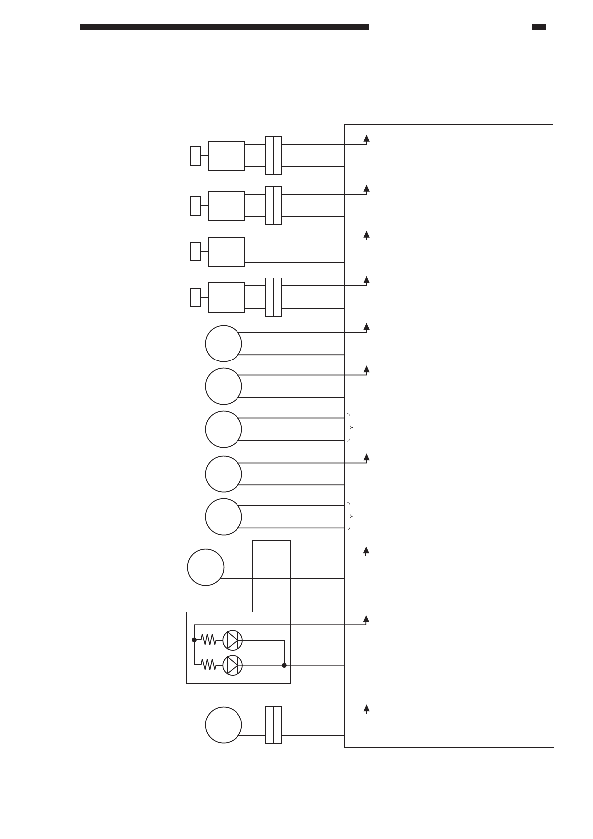
D. Outputs to the DADF Controller PCB
Stopper plate solenoid
When '0', the solenoid (SL1) turns on.
(The stopper plate moves down.)
SL1
J217
1
2
J5-10
-11
+24V
STPSL
2
1
Paper retaining plate
solenoid
When '0', the solenoid (SL2) turns on.
(The paper retaining plate moves down.)
SL2
J216
1
2
J5-12
-13
+24V
WGTSL
2
1
Stamp solenoid
When '0', the solenoid (SL4) turns on.
(The stamp puts a marking on the
original.)
SL4
J220
1
2
J14-9
-10
+24V
SMPSL
Clutch
When '0', the clutch (CL1)
turns on.
CL
J13-1
-2
+24V
CL
Brake
When '0', the brake (BK1)
turns on.
BK
J6-1
-2
+24V
BK
Pick-up motor
See p. 2-43.
M1
J12-1
-2
Feeder motor
When '0', the feeder motor (M2)
turns on.
M2
J11-1
-2
+24V
FMPWM
Belt motor
Delivery motor
See p. 2-45.
M3
J7-1
-2
When '0', the delivery motor (M5)
turns on.
M5
J14-8
-7
+24V
EMPWM
Re-circulation motor
Display PCB
LED101
LED102
When '0', the re-circulation motor (M4)
turns on.
M4
J8-5
-6
-3
-4
J102-1
-2
J101 -5
-6
-3
+5V
RSDRV
When '0', the Original Set indicator
turns on.
+5V
ORGLED
2
1
1
2
3
2
J221
J101-4
Paper deflecting plate
solenoid
When '0', the solenoid (SL3) turns on.
(The paper deflecting plate operates.)
SL3
J9-B2
-B1
+24V
FLPSL1
1. Outputs to the DADF Controller PCB (1/1)
CHAPTER 2 BASIC OPERATION
COPYRIGHT © 1998 CANON INC. CANON DADF-A1 REV.0 DEC. 1998 PRINTED IN JAPAN (IMPRIME AU JAPON)
2-5
CHAPTER 2 BASIC OPERATION
II . BASIC OPERATION
A. Outline
The machine uses four motors and one clutch to pick up, feed, and deliver originals.
The pick-up motor (M1) serves to pick up originals. The feeder motor (M2) serves to reverse and
deliver originals. The belt motor (M3) moves and stops originals to and on the copyboard glass, and
delivers them. The delivery motor (M3) operates to deliver originals to the delivery tray.
The clutch (CL) is used to engage or disengage the drive of the feeder motor (M2) and the belt
motor (M3).
DADF controller PCB
Belt motor clock signal
Feeder belt brake drive signal
Belt motor drive signal
Clutch drive signal
Feeder motor clock signal
S9
S10
Delivery detection signal 1
Reversal/feeder paper detection signal
Feeder motor drive signal
M2
CL
Paper deflecting plate solenoid drive signal
SL3
S6
S8
BK M3
Pick-up registration signal
S7
S3
S11
Registration roller clock signal
Pick-up paper detection signal
S1
Original tray paper signal
Pick-up roller home position detection signal
Upper cover open/closed detection signal 2
S4
S5
SL1
Paper holding solenoid drive signal
SL2
Last original detection signal
Stopper plate solenoid drive signal
Indicator
S14
M1
Delivery motor clock signal
Original set indicator ON signal
Re-circulator motor drive signal
PCB
S13
Pick-up motor drive signal
M4
M5
S12
SL4
Delivery detection signal 2
Delivery motor drive signal
Stamp solenoid drive signal
2-6
Figure 2-201
COPYRIGHT © 1998 CANON INC. CANON DADF-A1 REV.0 DEC. 1998 PRINTED IN JAPAN (IMPRIME AU JAPON)
CHAPTER 2 BASIC OPERATION
B. Operation
The machine enables the following six
operations:
1. Bottom pick-up
2. Double-sided original to single-sided
copy
3. 2 small-size originals to reduced page
composition
4. Single-sided original to double-sided
copy
5. Double-sided original to double-sided
copy
Using auto duplexing unit.
6. Top pick-up mode original feeding
The machine feeds originals in any of
the following five ways according to the
instructions from the copier:
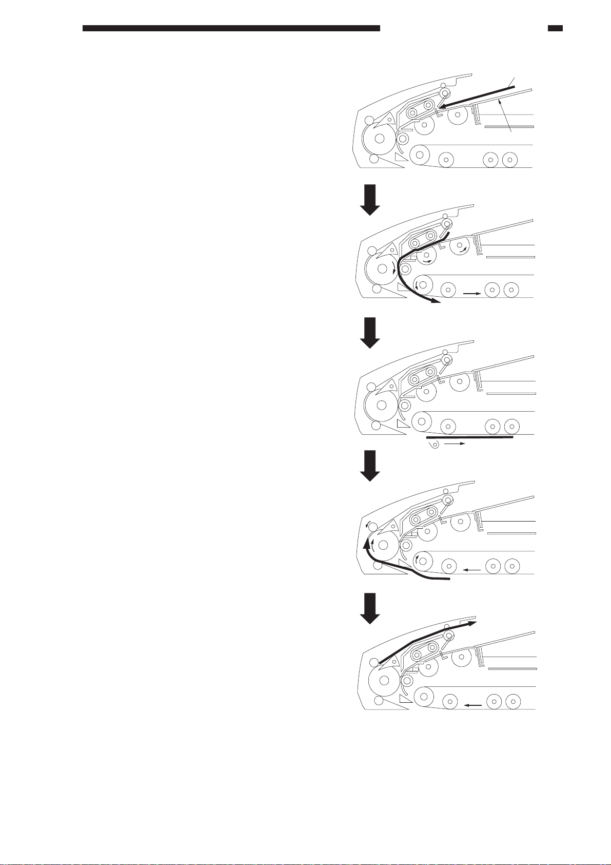
1. Bottom Pick-Up Mode
The machine picks up the originals on the
original tray from the bottom (last page of the
stack), and places each on the copyboard glass.
After copying, it moves the original from
the copyboard glass to the original tray.
Original
Original tray
Original set
Pick-up 2
Copying
Delivery 1
Delivery 2
Figure 2-202
COPYRIGHT © 1998 CANON INC. CANON DADF-A1 REV.0 DEC. 1998 PRINTED IN JAPAN (IMPRIME AU JAPON)
2-7
CHAPTER 2 BASIC OPERATION
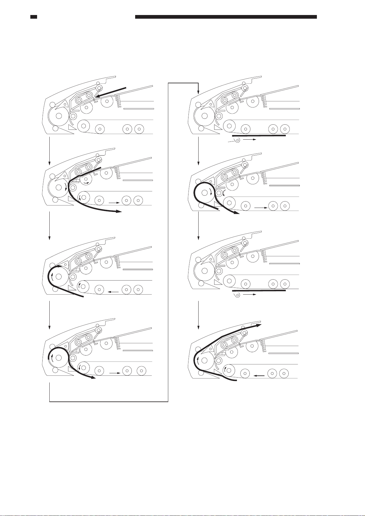
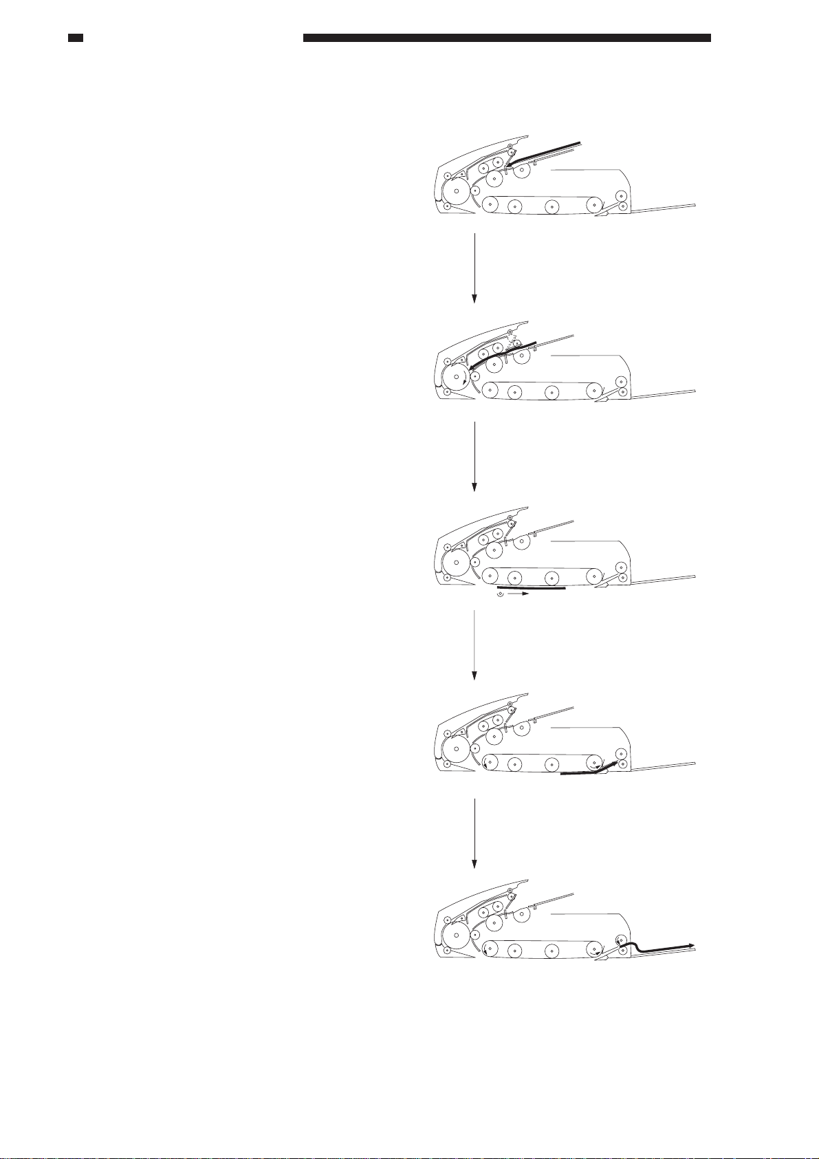
2. Double-Sided Original Mode
When copying the face (1st side) and the back (2nd side) of an original, the machine
automatically reverses the original.
Pick-Up Operation
Picks up an original for the 1st side.
Reverses the original from the 1st side
to the 2nd side.
Scanner
Reverses the original from the
2nd side to the 1st side.
Copies the 2nd side.
Copies the 1st side.
2-8
Delivers the original.
Figure 2-203
COPYRIGHT © 1998 CANON INC. CANON DADF-A1 REV.0 DEC. 1998 PRINTED IN JAPAN (IMPRIME AU JAPON)
CHAPTER 2 BASIC OPERATION
3. Reduced Page Compositon Mode
When reducing and copying two originals in page composition mode, the machine automatically
picks up two originals and places them on the copyboard glass side by side. Table 2-201 shows the
sizes of originals that may be used in the machine.
1st original
Picks up the 1st original.
A/B-configured
A5
B5
A4
Table 2-201
2nd original
INCH-configured
STMT
LTR
–
Reverses the original from the 1st side
to the 2nd side.
Picks up the 2nd original
While reversing the 1st original, picks up
the 2nd original.
(At this time, the order of originals is switched.)
Feeds the 2nd original and the 1st original.
Copying
1st original
2nd original
Delivers the 1st original, and delivers
the 2nd original.
Figure 2-204
COPYRIGHT © 1998 CANON INC. CANON DADF-A1 REV.0 DEC. 1998 PRINTED IN JAPAN (IMPRIME AU JAPON)
2-9
CHAPTER 2 BASIC OPERATION
4. Top Pick-Up Feeding
The machine picks up the originals on the
original tray from the top (first page of the
stack), and places them on the copyboard glass.
Each time an original has been read, the
machine moves the original from the
copyboard glass to the original delivery tray.
Placement
Pick-up
Reading
Delivery 1
Delivery 2
2-10
Figure 2-205
COPYRIGHT © 1998 CANON INC. CANON DADF-A1 REV.0 DEC. 1998 PRINTED IN JAPAN (IMPRIME AU JAPON)

CHAPTER 2 BASIC OPERATION
5. Recirculating Mode
If the copier is not equipped with a sorter, this mode enables sorting of copies. Originals are
copied one after another until one set of copies have been made; and this operation is repeated until as
many sets as desired have been made.
Operation
1) Set originals on the original tray.
2) Select sort mode on the copier.
3) Enter a number (of sets) on the copier’s keypad.
4) Press the Copy Start key.
COPYRIGHT © 1998 CANON INC. CANON DADF-A1 REV.0 DEC. 1998 PRINTED IN JAPAN (IMPRIME AU JAPON)
2-11
CHAPTER 2 BASIC OPERATION
C. Detecting Originals
1. Outline
The machine has the following four types
of document detection:
1. Detects the presence/absence of an
original on the original tray.
2. Detects the size of originals place on
the original try.
3. Detects the number of originals that
have been copied.
4. Detects the trailing edge of the last
original.
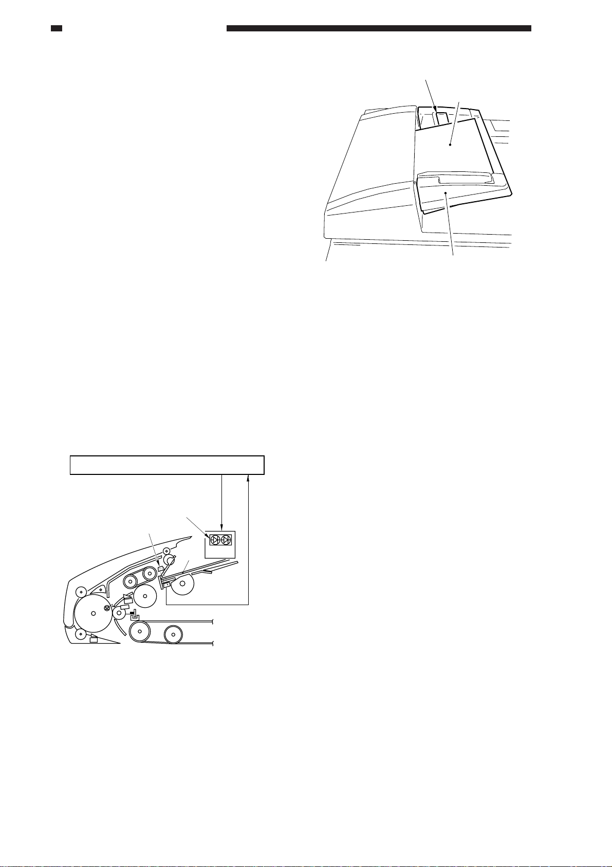
2. Detecting the Presence/Absence of
an Original
The presence/absence of an original on the
original tray is detected by the original tray
paper sensor (PS1).
When an original is set on the original tray,
the light between the original tray paper sensor
(S1) and the prism is blocked, causing the
original tray paper sensor (S1) to generate the
original detection signal (EMPS).
In response to the original detection signal
(EMPS), the DADF controller PCB turns on
the Original Set indicator (LED101, LED102).
Original Set indicator
Original
Original tray
Figure 2-207
DADF controller PCB
LED 101,102
Prism
Original
S1
S11
Figure 2-206
Original Set
indicator ON
signal
Indicator
PCB
Original tray paper signal
2-12
COPYRIGHT © 1998 CANON INC. CANON DADF-A1 REV.0 DEC. 1998 PRINTED IN JAPAN (IMPRIME AU JAPON)
CHAPTER 2 BASIC OPERATION
3. Detecting the Size of an Original
a. Outline
The machine detects the size of an original
in relation to the vertical (feeding) and
horizontal directions of the original, ensuring
correct size detection and for use for the
communication protocol of fax mode.
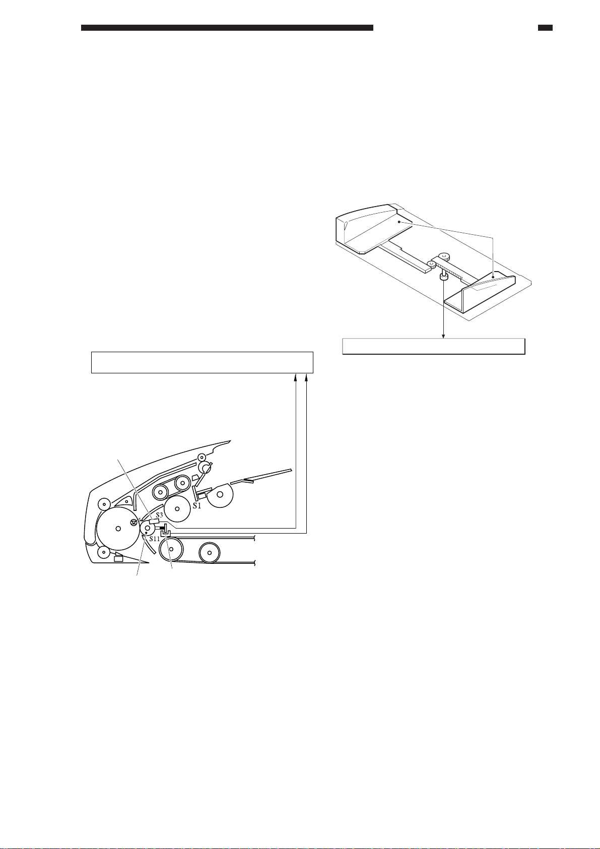
b. Detecting in Vertical (feeding)
Direction
Detection in vertical direction is made by
the registration paper sensor (S3) and the
registration roller clock sensor (S11).
The registration paper sensor detects the
leading and trailing edges of an original, and
the registration roller clock sensor detects the
rotation of the registration roller while the
original moves past the sensor. The rotation of
the registration roller is converted to the length
of the original.
DADF controller PCB
c. Detection in Horizontal Direction
Detection in horizontal direction is made
by the original width detecting volume (VR)
on the original tray. The original width
detecting volume operates in conjunction with
the side guide. As its resistance varies, the
changes are detected by the DADF controller
PCB, which converts them into a length in
horizontal direction.
Side guides
VR
DADF controller PCB
Figure 2-209
Registration
paper sensor
Registration roller
Pick-up detection signal
Registration roller clock signal
Registration roller clock sensor
Figure 2-208
COPYRIGHT © 1998 CANON INC. CANON DADF-A1 REV.0 DEC. 1998 PRINTED IN JAPAN (IMPRIME AU JAPON)
2-13

CHAPTER 2 BASIC OPERATION
The copier identifies the size of an original
in terms of a default size based on the results of
vertical and horizontal lengths communicated
by the machine.
Table 2-202 shows the default sizes that
are identified:
d. A Model, A/B Model
Default
B5R
A5
A4R
FOOLSCAP
B5
B4
COMPUTER
paper
A4
A3
Vertical length
257mm
148.5mm
330mm
330mm
182mm
364mm
381mm
210mm
420mm
Original width
177~187mm
205~215mm
252~262mm
274~284mm
292~302mm
f. Inch Model and Inch/AB Model
Default
B5R
A5
A4R
STMT
LTRR
FOOLSCAP
LGL
B5
B4
LTR
COMPUTER
paper
279mm×432mm
(11"×17")
A4
A3
Original
length
257mm
148mm
297mm
140mm
279mm
330mm
356mm
182mm
364mm
216mm
381mm
432mm
210mm
420mm
Original
width
177~187mm
205~213mm
214~221mm
252~262mm
274~284mm
For vertical direction, a deviation of ±10
mm is ignored; for horizontal direction, a
deviation of ±5 mm is ignored; outside the
ranges, the original will be identified as being
of a non-default size.
Table 2-202
e. Inch Model
Default
STMT
LTRR
FOOLSCAP
LGL
LTR
COMPUTER
paper
297mm×432mm
(11"×17")
Original
length
140mm
279mm
330mm
356mm
216mm
381mm
432mm
Original
width
211~221mm
274~284m
For original length, a deviation of ±10 mm
is ignored; for original width, a deviation of ±5
mm is ignored; outside the ranges, the original
will be identified as being of a non-default size.
Table 2-204
In vertical direction, a deviation of ±10 mm
is ignored; in horizontal direction, a deviation
of ±5 mm is ignored; outside the ranges, the
original will be identified as being of a nondefault size.
Table 2-203
2-14
COPYRIGHT © 1998 CANON INC. CANON DADF-A1 REV.0 DEC. 1998 PRINTED IN JAPAN (IMPRIME AU JAPON)
CHAPTER 2 BASIC OPERATION
4. Detecting the Number of Originals
The number of originals is detected in
terms of “stack end detection,” “last original
rear edge detection,” and “original count
detection.”
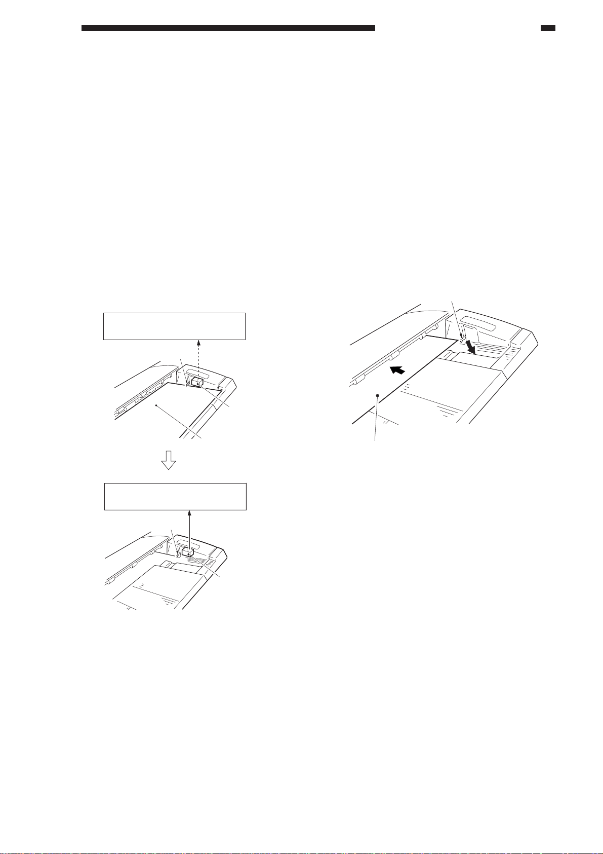
a. Detecting the End of a Stack
The machine picks up and delivers
originals on the same tray, requiring distinction
of originals that have been copied from
originals that have not been copied.
Before picking up originals, the recirculating lever is placed on top of the stack.
The lever will drop on the original tray when
all originals have been picked up, enabling the
re-circulation sensor (S14) to identify the last
original and to generate the last original
detection signal (RSS).
DADF controller PCB
Recirculating lever
b. Detecting the Trailing Edge of the Last
Original
A copier with a long paper path (from the
cassette to the drum) is designed to pick up
copy paper early to speed up copying work. As
such, when the machine picks up the last
original and places it on the copyboard glass,
the next paper is likely to be kept in wait.
To accommodate this, the machine is
designed to pick up originals to suit the timing
at which its host copier picks up copy paper.
If the length of an original is 220 mm or
less, the machine sets the first original on the
copyboard glass, and moves the second
original beyond the registration roller.
Recirculating lever
DADF controller PCB
Re-circulating
lever
Figure 2-210
Original
RSS
Re-circulation
sensor (S14)
Re-circulation
sensor (S14)
2nd original
Figure 2-211
If the re-circulating lever is on the original
tray in this condition, the machine
communicates to the copier that the third and
subsequent originals are present, and the copier
picks up copy paper for the next copying run.
When the re-circulating lever has dropped
on the original tray, the machine communicates
to the copier that there is not third or
subsequent originals (RSS signal) so that the
copier will not pick up copy paper.
COPYRIGHT © 1998 CANON INC. CANON DADF-A1 REV.0 DEC. 1998 PRINTED IN JAPAN (IMPRIME AU JAPON)
2-15
CHAPTER 2 BASIC OPERATION
c. Original Count Detection
The machine need not count originals
when making single-sided copies of singlesided originals, signal-sided originals of
double-sided originals, or double-sided copies
of double-sided originals; as such, it merely
feeds the originals on the original tray in
sequence.
When making double-sided copies of
signal-sided originals, however, the machine
must find out whether there is an odd or even
number of originals.
Holding the copier from making copies,
the DADF picks up and delivers the originals to
find out how many there are.
Reference:
The machine can pick up the last page of
originals first. When making doublesided copies of single-sided originals, it
must decide whether the last page must be
on the face or back of a sheet (odd or even
page).
Figure 2-212 shows what would happen
if an odd number originals were fed
without control. (The first page would be
copied on the back of a sheet.)
1
2
3
1
2
3
Copier
Figure 2-212
On some copiers, you can disable original
count operation in user mode.
2-16
COPYRIGHT © 1998 CANON INC. CANON DADF-A1 REV.0 DEC. 1998 PRINTED IN JAPAN (IMPRIME AU JAPON)
 Loading...