

Canon Finisher-T1 Service Manual
SERVICE
MANUAL
Finisher-T1
DU7-1145-000
JAN. 2005
REV. 0
COPYRIGHT 2005 CANON INC. CANON Finisher-T1 REV. 0 PRINTED IN U.S.A.

Application
This manual has been issued by Canon Inc. for qualified persons to learn technical theory, installation,
maintenance, and repair of products. This manual covers all localities where the products are sold. For
this reason, there may be information in this manual that does not apply to your locality.
Corrections
This manual may contain technical inaccuracies or typographical errors due to improvements or changes
in products. When changes occur in applicable products or in the contents of this manual, Canon will
release technical information as the need arises. In the event of major changes in the contents of this
manual over a long or short period, Canon will issue a new edition of this manual.
The following paragraph does not apply to any countries where such provisions are inconsistent with
local law.
Trademarks
The product names and company names used in this manual are the registered trademarks of the
individual companies.
Copyright
This manual is copyrighted with all rights reserved. Under the copyright laws, this manual may not be
copied, reproduced or translated into another language, in whole or in part, without the written consent
of Canon Inc.
COPYRIGHT © 2001 CANON INC.
Printed in Japan
Caution
Use of this manual should be strictly supervised to avoid disclosure of confidential information.

Introduction
Symbols Used
This documentation uses the following symbols to indicate special information:
Symbol Description
Indicates an item of a non-specific nature, possibly classified as Note,
Caution, or Warning.
Indicates an item requiring care to avoid electric shocks.
Indicates an item requiring care to avoid combustion (fire).
Indicates an item prohibiting disassembly to avoid electric shocks or
problems.
Indicates an item requiring disconnection of the power plug from the electric
outlet.
Memo
REF.
Indicates an item intended to provide notes assisting the understanding of the
topic in question.
Indicates an item of reference assisting the understanding of the topic in
question.
Provides a description of a service mode.
Provides a description of the nature of an error indication.

Introduction
The following rules apply throughout this Service Manual:
1. Each chapter contains sections explaining the purpose of specific functions and the
relationship between electrical and mechanical systems with reference to the timing of
operation.
In the diagrams, represents the path of mechanical drive; where a signal name
accompanies the symbol, the arrow indicates the direction of the electric
signal.
The expression "turn on the power" means flipping on the power switch, closing the front
door, and closing the delivery unit door, which results in supplying the machine with
power.
2. In the digital circuits, '1'is used to indicate that the voltage level of a given signal is
"High", while '0' is used to indicate "Low".(The voltage value, however, differs from
circuit to circuit.) In addition, the asterisk (*) as in "DRMD*" indicates that the DRMD
signal goes on when '0'.
In practically all cases, the internal mechanisms of a microprocessor cannot be checked
in the field. Therefore, the operations of the microprocessors used in the machines are
not discussed: they are explained in terms of from sensors to the input of the DC
controller PCB and from the output of the DC controller PCB to the loads.
The descriptions in this Service Manual are subject to change without notice for product
improvement or other purposes, and major changes will be communicated in the form of
Service Information bulletins.
All service persons are expected to have a good understanding of the contents of this
Service Manual and all relevant Service Information bulletins and be able to identify and
isolate faults in the machine."

Contents
Contents
Chapter 1 Specifications
1.1 Product Specifications ............................................................................................... 1-1
1.1.1 Specification........................................................................................................ 1-1
1.2 Names of Parts ........................................................................................................... 1-5
1.2.1 External View ..................................................................................................... 1-5
1.2.2 Cross Section....................................................................................................... 1-6
Chapter 2 Functions
2.1 Basic Operation.......................................................................................................... 2-1
2.1.1 Basic Operation................................................................................................... 2-1
2.1.2 Overview of the Electrical Circuitry................................................................... 2-2
2.2 Feed Drive System..................................................................................................... 2-3
2.2.1 Overview ............................................................................................................. 2-3
2.2.2 Constraction of the Control System .................................................................... 2-4
2.2.3 Paper Delivery Path ............................................................................................ 2-7
2.3 Intermediate Process Tray Assembly ...................................................................... 2-12
2.3.1 Stack Job Offset ................................................................................................ 2-12
2.3.2 Processing Tray Paper Stacking Operation....................................................... 2-14
2.3.3 Offset Operation................................................................................................ 2-15
2.3.4 Rear End Assist Operation ................................................................................ 2-16
2.3.5 Stack Delivery Operation.................................................................................. 2-17
2.4 Staple Operation ...................................................................................................... 2-18
2.4.1 Stapler Unit ....................................................................................................... 2-18
2.4.2 Shifting the Stapler Unit ................................................................................... 2-20
2.4.3 Stapling Operation ............................................................................................ 2-23
2.5 Stack Tray Operation ............................................................................................... 2-29
2.5.1 Tray Operation .................................................................................................. 2-29
2.5.2 Shutter Operation .............................................................................................. 2-33
2.6 Detecting Jams ......................................................................................................... 2-34
2.6.1 Detecting Jams (Finisher Unit) ......................................................................... 2-34
2.7 Power Supply........................................................................................................... 2-37
2.7.1 Power Supply Route.......................................................................................... 2-37

Contents
2.7.2 Protection Function ........................................................................................... 2-38
Chapter 3 Parts Replacement Procedure
3.1 External Covers.......................................................................................................... 3-1
3.1.1 Rear Upper Cover ............................................................................................... 3-1
3.1.2 Grate-shaped Upper Guide ..................................................................................3-1
3.1.3 Grate-shaped Lower Guide ................................................................................. 3-1
3.1.4 Front Inside Upper Cover .................................................................................... 3-2
3.1.5 Front Door ...........................................................................................................3-3
3.1.6 Escape Tray Cover .............................................................................................. 3-4
3.1.7 Escape Door ........................................................................................................3-4
3.2 Drive System.............................................................................................................. 3-5
3.2.1 Stapler .................................................................................................................3-5
3.2.2 Swing Unit .......................................................................................................... 3-6
3.3 Document Feeding System ........................................................................................ 3-9
3.3.1 Process Tray Assembly .......................................................................................3-9
3.3.2 Tray 1 ................................................................................................................3-11
3.3.3 Tray 2 ................................................................................................................3-13
3.3.4 Buffer Roller .....................................................................................................3-15
3.3.5 Return Roller .....................................................................................................3-16
3.3.6 Return Roller Unit ............................................................................................. 3-17
3.3.7 Escape Unit ....................................................................................................... 3-18
3.3.8 Escape Door Unit .............................................................................................. 3-20
3.4 Electrical System ..................................................................................................... 3-21
3.4.1 Finisher Controller PCB ....................................................................................3-21
3.4.2 Static Charge Eliminator 1 ................................................................................3-22
3.4.3 Static Charge Eliminator 2 ................................................................................3-23
3.4.4 Static Charge Eliminator 3 ................................................................................3-24
Chapter 4 Maintenance
4.1 User Maintenance ...................................................................................................... 4-1
4.1.1 User Maintenance (Finisher Unit) ....................................................................... 4-1
4.2 Maintenance and Inspection ...................................................................................... 4-2
4.2.1 Periodically Replaced Parts ................................................................................. 4-2
4.2.1.1 Periodically Replaced Parts (Finisher Unit) ................................................. 4-2
4.2.2 Durables .............................................................................................................. 4-2
4.2.2.1 Durables (Finisher Unit)............................................................................... 4-2

Contents
4.2.3 Periodical Servicing ............................................................................................ 4-3
4.2.3.1 Periodical Servicing (Finisher Unit) ............................................................ 4-3
4.3 Adjustment................................................................................................................. 4-4
4.3.1 Basic Adjustment ................................................................................................ 4-4
4.3.1.1 Upward Curl Mode....................................................................................... 4-4
4.3.1.2 Special Curl Mode........................................................................................ 4-4
4.3.1.3 Downward Curl Mode.................................................................................. 4-5
4.3.1.4 Heavy Paper Upward Curl Mode ................................................................. 4-6
4.3.1.5 Stack Delivery Mode.................................................................................... 4-7
4.3.1.6 Offset Stack Mode........................................................................................ 4-8
4.3.2 Adjustment at Time of Parts Replacement ......................................................... 4-8
4.3.2.1 Adjusting the Alignment Position................................................................ 4-8
4.3.2.2 Adjusting the Staple Position ....................................................................... 4-9
4.4 Troubleshooting....................................................................................................... 4-11
4.4.1 Error Code ......................................................................................................... 4-11
4.4.1.1 E500;Communication error........................................................................ 4-11
4.4.1.2 E505;Backup RAM error ........................................................................... 4-11
4.4.1.3 E514;Rear end assist motor error ............................................................... 4-11
4.4.1.4 E530;Front aligning plate motor error ....................................................... 4-12
4.4.1.5 E531;Staple motor error ............................................................................. 4-12
4.4.1.6 E532;Stapler shift motor error.................................................................... 4-12
4.4.1.7 E535;Swing motor error............................................................................. 4-13
4.4.1.8 E537;Rear aligning plate motor error......................................................... 4-13
4.4.1.9 E540;Tray 1 shift motor error .................................................................... 4-14
4.4.1.10 E542;Tray 2 shift motor error .................................................................. 4-14
4.4.1.11 E584;Shutter malfunction ........................................................................ 4-15
4.5 Outline of Electrical Components............................................................................ 4-16
4.5.1 Sensors (Finisher Unit) ..................................................................................... 4-16
4.5.2 Microswitches (Finisher Unit) .......................................................................... 4-19
4.5.3 Solenoids (Finisher Unit) .................................................................................. 4-21
4.5.4 Motors (Finisher Unit) ...................................................................................... 4-23
4.5.5 Clutches (Finisher Unit).................................................................................... 4-25
4.5.6 PCBs (Finisher Unit)......................................................................................... 4-26
4.6 Variable Resistors (VR), Light-Emitting Diodes (LED), and Check Pins by PCB. 4-28
4.6.1 Overview ........................................................................................................... 4-28
4.6.2 Finisher Controller PCB.................................................................................... 4-28
4.7 Upgrading ................................................................................................................ 4-30
4.7.1 Upgrading (Finisher Unit)................................................................................. 4-30
4.8 Service Tools ........................................................................................................... 4-40
4.8.1 Solvents and Oils .............................................................................................. 4-40

Contents
Chapter 5 Error Code
5.1 Overview.................................................................................................................... 5-1
5.1.1 Overview ............................................................................................................. 5-1
5.2 User Error Code ......................................................................................................... 5-2
5.2.1 Staple is absent .................................................................................................... 5-2
5.2.2 Stapler safety protection function activated........................................................ 5-2
5.2.3 Stack tray overstacking ....................................................................................... 5-3
5.3 Service Error Code..................................................................................................... 5-4
5.3.1 E500 .................................................................................................................... 5-4
5.3.2 E505 .................................................................................................................... 5-4
5.3.3 E514 .................................................................................................................... 5-4
5.3.4 E530 .................................................................................................................... 5-5
5.3.5 E531 .................................................................................................................... 5-5
5.3.6 E532 .................................................................................................................... 5-6
5.3.7 E535 .................................................................................................................... 5-6
5.3.8 E537 .................................................................................................................... 5-7
5.3.9 E540 .................................................................................................................... 5-8
5.3.10 E542 .................................................................................................................. 5-9
5.3.11 E584 ................................................................................................................ 5-10
5.3.12 Temporary Functional Limit ........................................................................... 5-10

Chapter 1
Specifications

Contents
Contents
1.1 Product Specifications ............................................................................................... 1-1
1.1.1 Specification........................................................................................................ 1-1
1.2 Names of Parts ........................................................................................................... 1-5
1.2.1 External View ..................................................................................................... 1-5
1.2.2 Cross Section....................................................................................................... 1-6

1.1 Product Specifications
Chapter 1
1.1.1 Specification
Item Specifications
Stacking method
Stacking
orientation
Stacking size*1
Paper weight
Modes
Stacking
capacity*2, *3
Escape tray: fixed type
Trays 1 and 2: Independently move up and down
Face up
Face down
A3, A4, A4R, A5R, B4, B5, B5R, 279 mm x 432 mm (11 x 17), LGL,
LTR, LTRR, STMTR, others
64g/m2 to 200g/m2
Non sort:Escape tray
:Trays 1 and 2
Sort: Trays 1 and 2
Staple: Trays 1 and 2
Escape tray: Non sort
Large size: 43 mm high (125 sheets)
Small size: 43 mm high (250 sheets)
0009-2494
T-1-1
Tray 1: Non sort
Large size: 96 mm high (650 sheets)
Small size: 188 mm high (1300 sheets)
Tray 2: Non sort
Large size: 96 mm high (650 sheets)
Small size: 243 mm high (1700 sheets)
Small size: 347 mm high (2450 sheets)*4
Tray 1: Staple sort
1-1

Chapter 1
Item Specifications
Large size: 96 mm high/50 sets
Small size: 188 mm high/100 sets
Tray 2: Staple sort
Large size: 96 mm high/50 sets
Small size: 188 mm high/100 sets
Mixed stacking
capac-ity
Size mixing:
Escape tray: 43 mm high
Tray 1 and 2: 96 mm high (650 sheets)
Stapling:
96 mm high/50 sets
Mode mixing:
Large size: 96 mm high/50 sets
Small size: 188 mm high/100 sets
Stapling
Stapling
capacity
By rotating cam
Small size: 50 sheets
Large size: 30 sheets
*1 Feed direction: 139.7 to 420.0 mm: cross feed direction: 98.4 to 297.0 mm
*2 Equivalent of 80g/m2 paper.
*3 Alignment accuracy and stacking capacity for stacks of 1700 or more sheets are not
specified.
*4 This applies when sheets (A4, B5, or LTR) of the same size are stacked in the non-sort
mode.
*5 Stacking capacity is not guaranteed.
*6 The paper thickness is 5.5 mm or less.
1-2

Chapter 1
T-1-2
Item Specifications Remarks
Staple supply Special staple cartridge (5000 staples)
Staple detection Provided 0 to 20 remaining
staples
Manual stapling Not provided
Stapling size Front 1-point stapling (30 deg.)
A4R, LGL, LTRR
Front 1-point stapling (45 deg.)
A3, B4, A4, B5, 279mm x 432mm (11 x 17), LTR
Rear 1-point stapling (30 deg.)
A4R, LGL, LTRR
Rear 1-point stapling (45 deg.)
A3, B4, A4, B5, 279mm x 432mm (11 x 17), LTR
2-point stapling
A3, A4, A4R, B4, B5, 279mm x 432mm (11 x 17), LGL,
LTR, LTRR
Paper detection Provided
Control panel Not provided
Display Not provided
Dimensions W:649(761) x D:656 x H:1108mm If within
parentheses, with
the tray
extended.
Weight
Power supply From host machine (24VDC)
Maximum power
consumption
Approx. 48 kg
5.3 W or less during standby/110 W or less
operating
1-3
Chapter 1
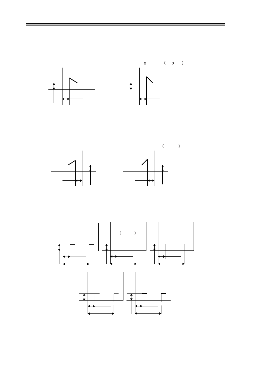
<Stapling Positions>
Front 1-point stapling (30deg.)
A4R, LGL, and LTRR
5-/+2mm
5-/+2mm
Rear 1-point stapling (30deg.)
A4R, LGL, and LTRR
5-/+2mm
5-/+2mm
2-point stapling
A3 and A4
Front 1-point stapling (45deg.)
A3, A4, B4, B5,
279mm 432mm 11 17 ,and LTR
5-/+2mm
5-/+2mm
F-1-1
Rear 1-point stapling (45deg.)
A3, A4, B4, B5,
279mm x 432mm
5-/+2mm
11 x 17 , and LTR
5-/+2mm
F-1-2
279mm x 432mm
11 x 17
and LTR
B4 and B5
1-4
203-/+4mm
5-/+2mm
83-/+4mm
5-/+2mm
5-/+2mm
A4R
39.5-/+4mm
159.5-/+4mm
74-/+4mm
194-/+4mm
F-1-3
63-/+4mm
183-/+4mm
5-/+2mm
LGL and LTRR
42.5-/+4mm
162.5-/+4mm
5-/+2mm
1.2 Names of Parts
Chapter 1
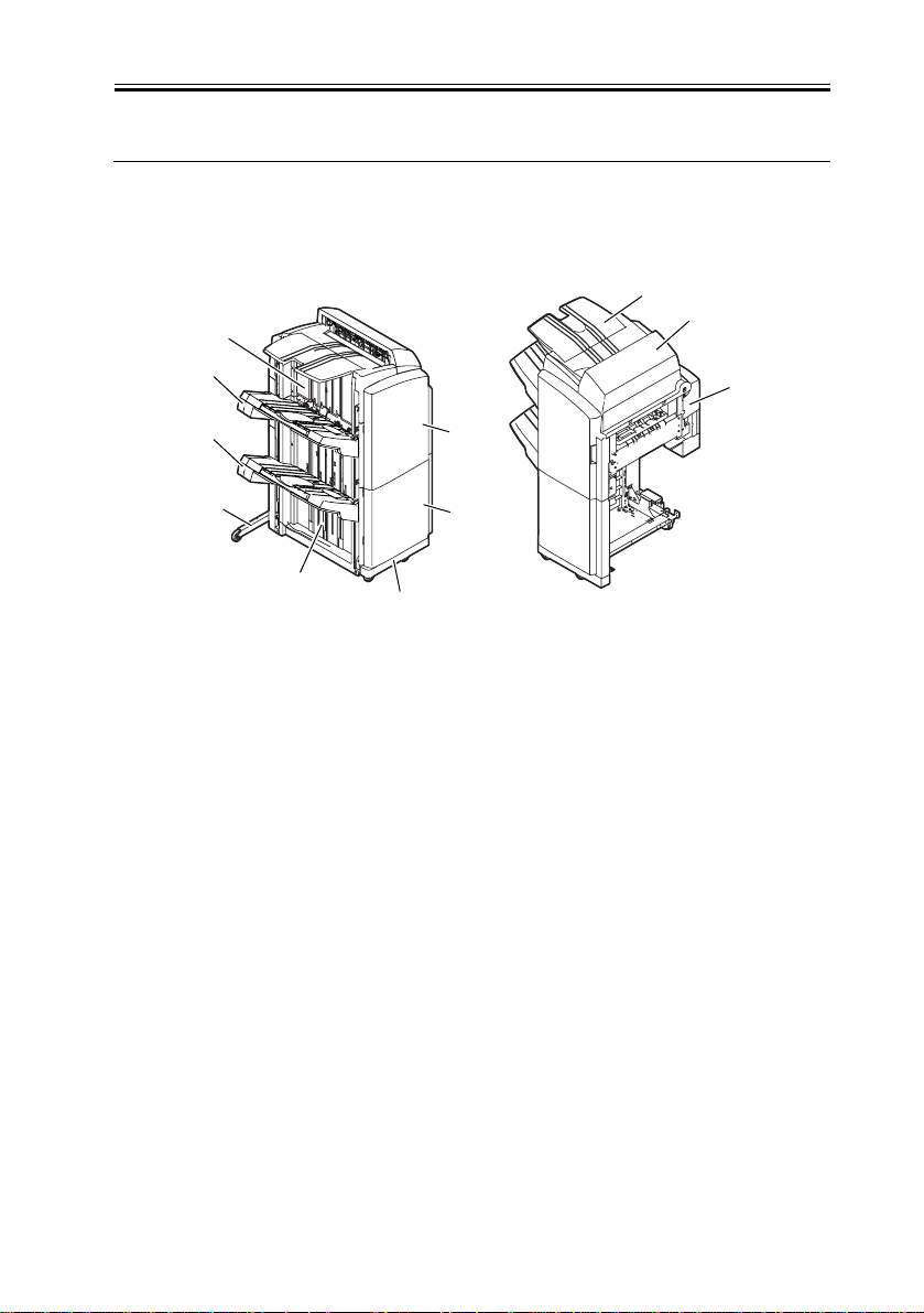
1.2.1 External View
[7]
[8]
[9]
[10]
[11]
[1] Escape tray [7] Grate-shaped upper guide
[2] Escape door [8] Tray 1
[3] Rear upper cover [9] Tray 2
[4]
[5]
[6]
F-1-4
T-1-3
0009-2506
[1]
[2]
[3]
[4] Front door [10] Auxiliary plate
[5] Front lower cover [11] Grate-shaped lower guide
[6] Foot cover
1-5
Chapter 1
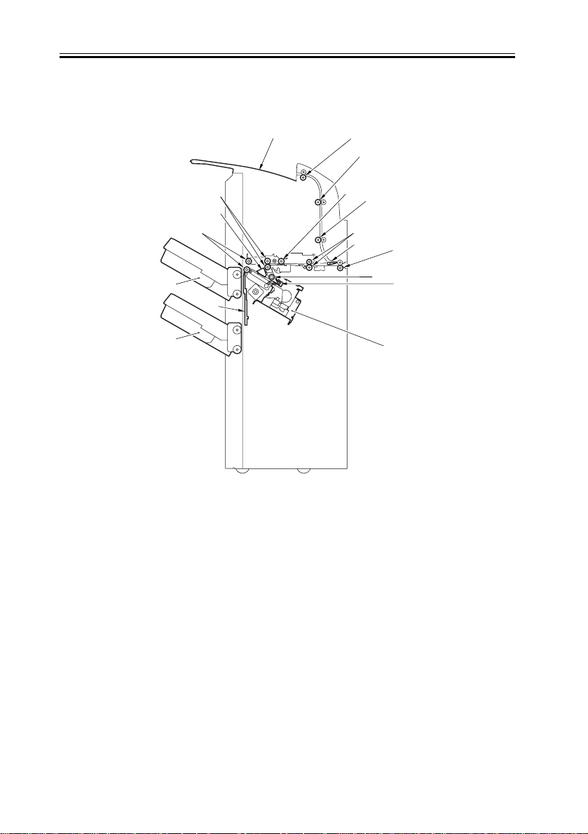
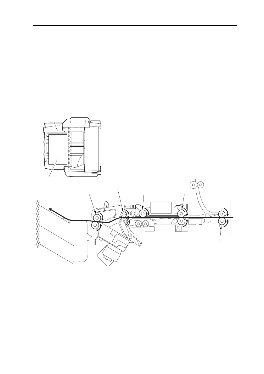
1.2.2 Cross Section
[1]
[2]
[4]
[3]
[6]
[5]
[7]
F-1-5
[8]
[10]
[9]
[11]
[16]
[9]
[13]
0009-2507
[12]
[14]
[15]
T-1-4
[1] Tray 1 [9] Escape feed roller
[2] Tray 2 [10] Buffer roller
[3] Shutter [11] Feed roller
[4] Stack delivery roller [12] Inlet roller
[5] Aligning plate [13] Return roller
[6] 1st delivery roller [14] Rear end assist guide
[7] Escape tray [15] Stapler
[8] Escape delivery roller [16] Escape inlet flapper
1-6

Chapter 2
Functions

Contents
Contents
2.1 Basic Operation.......................................................................................................... 2-1
2.1.1 Basic Operation................................................................................................... 2-1
2.1.2 Overview of the Electrical Circuitry................................................................... 2-2
2.2 Feed Drive System..................................................................................................... 2-3
2.2.1 Overview ............................................................................................................. 2-3
2.2.2 Constraction of the Control System .................................................................... 2-4
2.2.3 Paper Delivery Path ............................................................................................ 2-7
2.3 Intermediate Process Tray Assembly ...................................................................... 2-12
2.3.1 Stack Job Offset ................................................................................................ 2-12
2.3.2 Processing Tray Paper Stacking Operation....................................................... 2-14
2.3.3 Offset Operation................................................................................................ 2-15
2.3.4 Rear End Assist Operation ................................................................................ 2-16
2.3.5 Stack Delivery Operation.................................................................................. 2-17
2.4 Staple Operation ...................................................................................................... 2-18
2.4.1 Stapler Unit ....................................................................................................... 2-18
2.4.2 Shifting the Stapler Unit ................................................................................... 2-20
2.4.3 Stapling Operation ............................................................................................ 2-23
2.5 Stack Tray Operation ............................................................................................... 2-29
2.5.1 Tray Operation .................................................................................................. 2-29
2.5.2 Shutter Operation .............................................................................................. 2-33
2.6 Detecting Jams ......................................................................................................... 2-34
2.6.1 Detecting Jams (Finisher Unit) ......................................................................... 2-34
2.7 Power Supply........................................................................................................... 2-37
2.7.1 Power Supply Route.......................................................................................... 2-37
2.7.2 Protection Function ........................................................................................... 2-38

2.1 Basic Operation
Chapter 2
2.1.1 Basic Operation
0009-2508
The finisher is designed to deliver copies arriving from its host machine, and its modes of
delivery include simple stacking, job offset, and staple.
All operations involved in these modes are controlled by the finisher controller PCB,
according to the appropriate commands from the host machine.
Swing guide drive system
Alignment drive system
Tray drive system
Control system
Tray drive system
Stapler drive system
Delivery drive system
Feeder drive system
Shutter drive system
F-2-1
Memo: The term job offset refers to shifting each sorting job, separating a single stack into
several stacks.
2-1
Chapter 2
2.1.2 Overview of the Electrical Circuitry
0009-2509
The finisher's sequence of operation is controlled by the finisher controller PCB. The finisher
controller PCB is a 16-bit microprocessor (CPU), and is used for communication with the host
machine (serial) in addition to controlling the finisher's sequence of operations.
The finisher controller PCB responds to the various commands coming from the host machine
through a serial communications line to drive solenoids, motors, and other loads. In addition, it
communicates the finisher's various states (information on sensors and switches) to the host
machine through a serial communications circuit.
The ICs used on the finisher controller PCB are designed for the following:
<IC108 (CPU)>
Controls sequence of operations.
Contains sequence programs.
<IC105 (EEP-ROM)>
Backs up adjustment values.
Backs up initial setting data.
<IC107 (communications IC)>
Communicates with the host machine and the saddle stitcher unit.
<IC102 (regulator IC)>
Generates 5V.
<IC109 (regulator IC)>
Generates 3.3V.
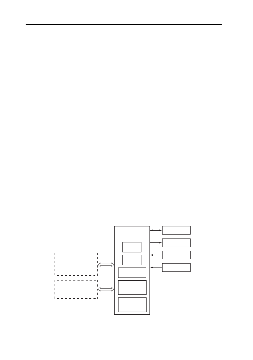
The following figure shows the flow of signals between the finisher and the options controller.
Motor
Solenoid
Switch
Sensor
Punch controller PCB
(Puncher unit (option))
Host machine
(DC controller PCB CPU)
Finisher controller
PCB
IC108
CPU
IC105
EEP-ROM
IC107
Communications IC
IC102
Regulator IC
IC109
Regulator IC
F-2-2
2-2
2.2 Feed Drive System
Chapter 2
2.2.1 Overview
0009-2510
This product consists of the Finisher unit and the Saddle Stitcher unit.
The Finisher unit simply stacks sheets delivered from a host machine, offsets a stack job, or
staples and delivers the sheets to the trays according to commands delivered from a host
machine.
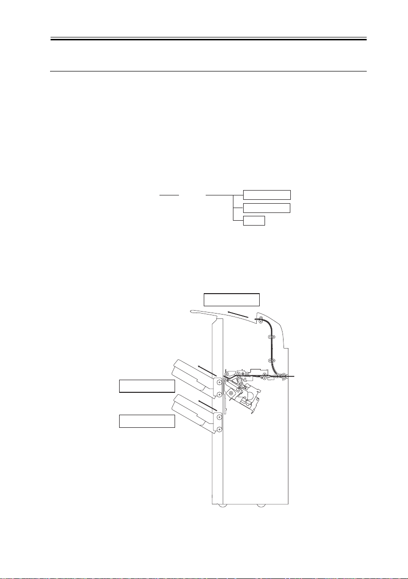
There are three delivery methods.
Method of delivery
Normal
delivery
Simple stacking
Stack job offset
Staple
Front 1-point stapling
Rear 1-point stapling
2-point stapling
F-2-3
Escape tray
Normal delivery tray
Normal delivery tray
F-2-4
2-3

Chapter 2
2.2.2 Constraction of the Control System
The copy sent from the host machine is delivered to the ejection tray, escape tray, or
processing tray according to the ejection type. Job offset or stapling is performed,
according to the instruction from the host machine, for copy delivered to the staple tray.
When ejecting from the processing tray, rear end assist guide is used in addition to the stack
ejection roller to eject the stack.
The feed motor (M101), stack ejection motor (M102), rear end assist motor (M109), escape
feed motor (M112), and inlet motor (M113) are step motors. These motors are rotated
forward or backward by the microcomputer (CPU) in the finisher controller PCB.
The following three sensors are provided in the copy delivery path to detect the arrival or
passing of copies.
- Inlet sensor (PI103)
- Delivery path sensor (PI104)
- Escape tray path sensor (PI118)
Also, each ejection tray has sensors to detect the presence of copy on the tray.
First tray paper sensor (PI111)
Second tray paper sensor (PI112)
If the copy does not reaches or passes each sensor within prescribed time, the finisher
controller PCB determines that the jam has occurred and stops the operation. Then it
notifies the host machine that a jam has occurred. When all of the doors are closed after
fixing the jam, the finisher checks whether copy is detected by any of the above three
sensors (inlet sensor, delivery path sensor, escape tray path sensor). If any of the sensors
detects a copy, the finisher determines that the jam is not fixed and sends jam processing
signal to the host machine once more.
0009-2511
2-4
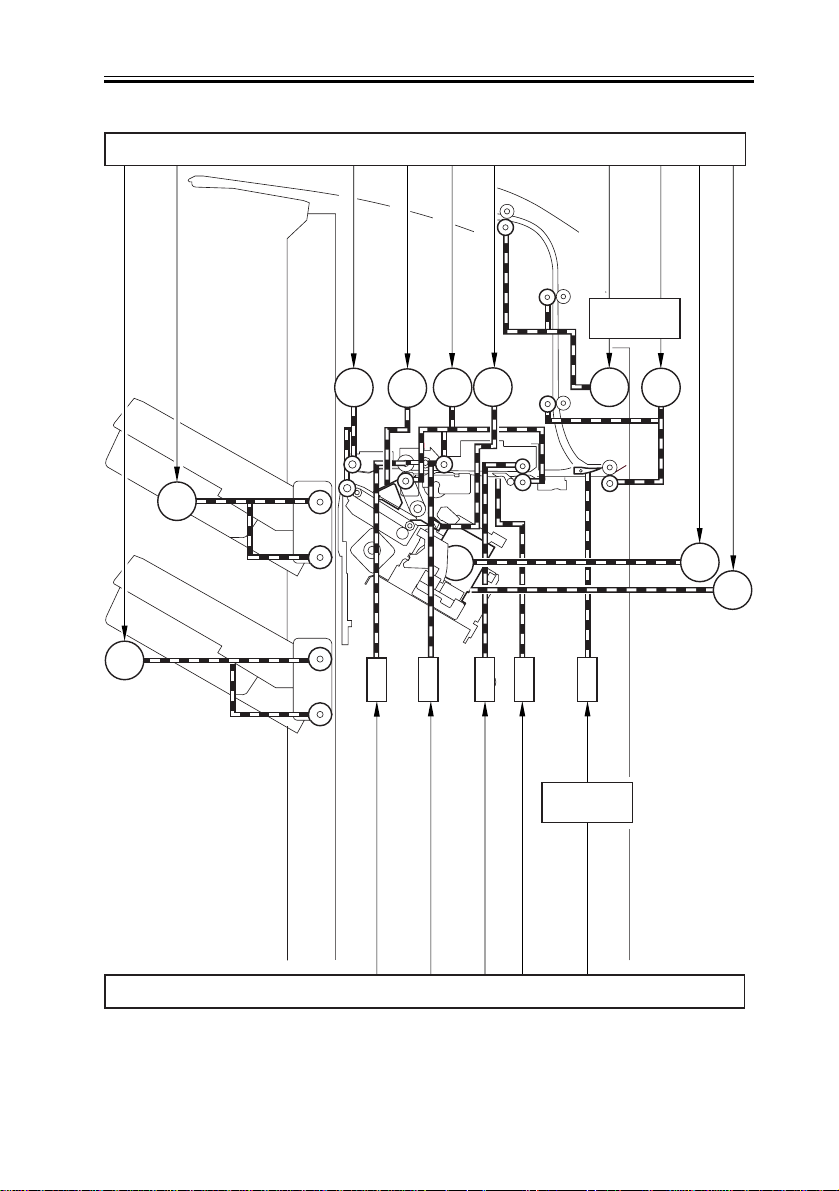
Second tray shift motor drive signal
First tray shift motor drive signal
M107
Finisher controller PCB(1/2)
Feed motor drive signal
Aligning plate front/rear
motor drive signal
Stack ejection motor drive signal
M103
M33
M102 M101
M104
Rear end assist motor drive signal
M109
Escape feed motor
drive signal
Feed driver
PCB
M112
Chapter 2
inlet motor drive signal
Stapler motor drive signal
Stapler drive motor drive signal
M113
M105
M111
M108
SL102
SL103
Buffer roller separation solenoid drive signal
1st eject roller separation solenoid drive signal
Finisher controller PCB(2/2)
F-2-5
SL101
Feed roller separation solenoid drive signal
SL104
Buffer rear end holding solenoid drive signal
SL105
Feed driver
PCB
Escape solenoid
drive signal
2-5
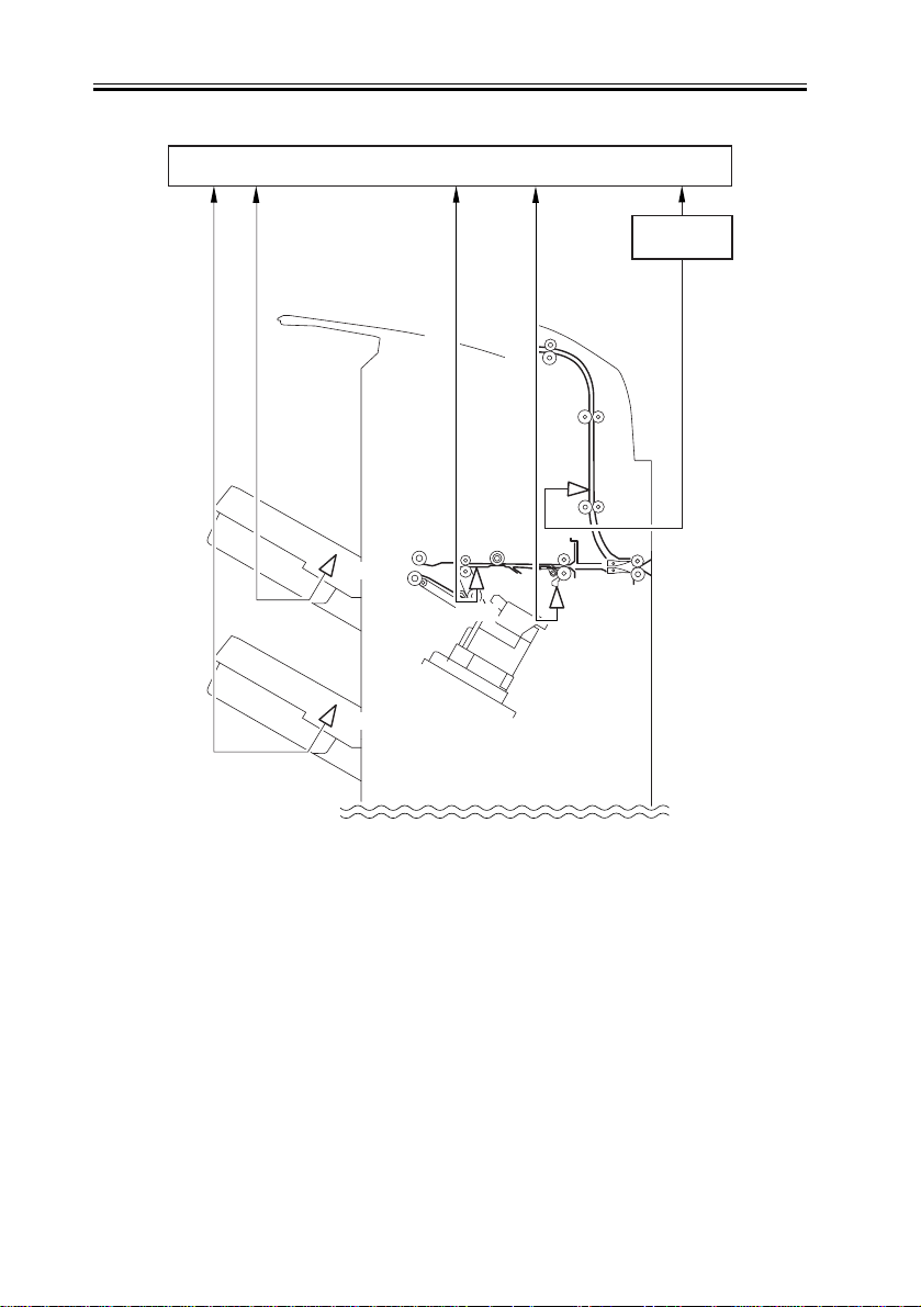
Chapter 2
Finisher controller PCB
Feed driver
PCB
First tray paper detection signal
Second tray paper detection signal
PI111
PI112
Inlet paper detection signal
Feed path paper detetion signal
PI118
PI104
F-2-6
PI103
Escape tray path paper
detection signal
2-6
Chapter 2
2.2.3 Paper Delivery Path
0009-2512
<Overview>
There are three ejection paths to tray 1 and 2 depending on the ejection processing. There
is only one paper ejection path to the escape tray.
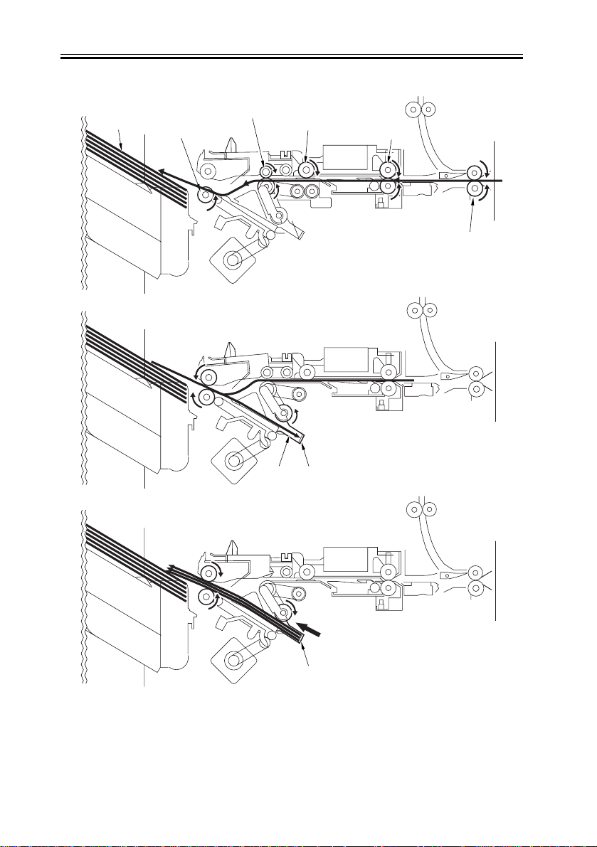
<Straight Ejection (Destination: Tray 1/ Tray 2)>
When the equipment is set to non-sort, all copies are ejected through the following path.
Stack ejection roller
Tr ay
Paper
Stack ejection roller
1st delivery roller
Buffer roller
Feed roller
Inlet roller
F-2-7
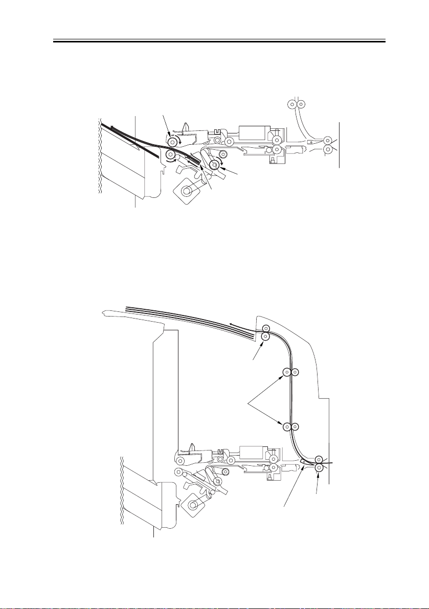
<Processing Tray Path (Destination: Tray 1/ Tray 2)>
This is the copy ejection path when the equipment is set to sort for paper size other than A4,
B5, or LTR or when set to staple sort. Copies are delivered to the processing tray for
aligning and stapling. Then they are ejected using the rear end assist.
2-7
Chapter 2
Paper
1st delivery roller
Stack ejection roller
Buffer roller
Paper
Feed roller
Inlet roller
Processing tray
2-8
Rear end assist
F-2-8
Chapter 2
r
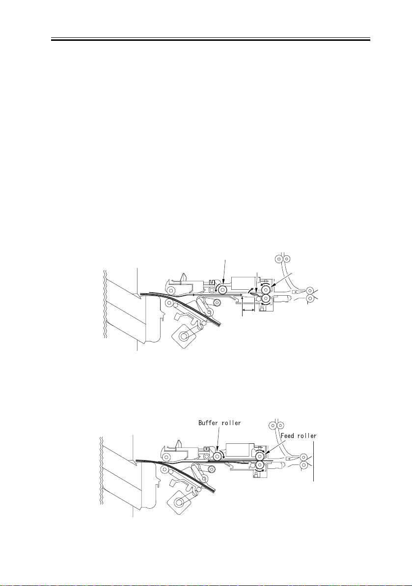
<Buffer/Processing Tray Path (Destination: Tray 1/ Tray 2)>
This is the copy ejection path when the equipment is set to sort for A4, B5, or LTR paper
size. Feed two sheets of paper to buffer (two or three sheets if 2-point stapling). Then they
are aligned and stapled in the processing tray and ejected. Even while stapling or offset is
being performed, simultaneous stack ejection, which simultaneously ejects copies delivered
to the buffer and post processed stack in the processing tray, is performed because copies
are received continuously from the host machine. The stack delivered from the buffer is
ejected to the processing tray and the stack processed in the processing tray is ejected to the
tray.
Simultaneous stack ejection operation is described below for two A4 copies between stacks
when the equipment is set to sort.
1) When the 1st paper reaches the switchback point, it is sent to the buffer unit and the rear
end of the paper is held by the buffer guide.
Buffer roller
Buffer guide
20mm
Switch back point
Feed rolle
F-2-9
2) When the first copy is delivered to the buffer, the second copy is delivered from the host
machine.
F-2-10
2-9
Chapter 2
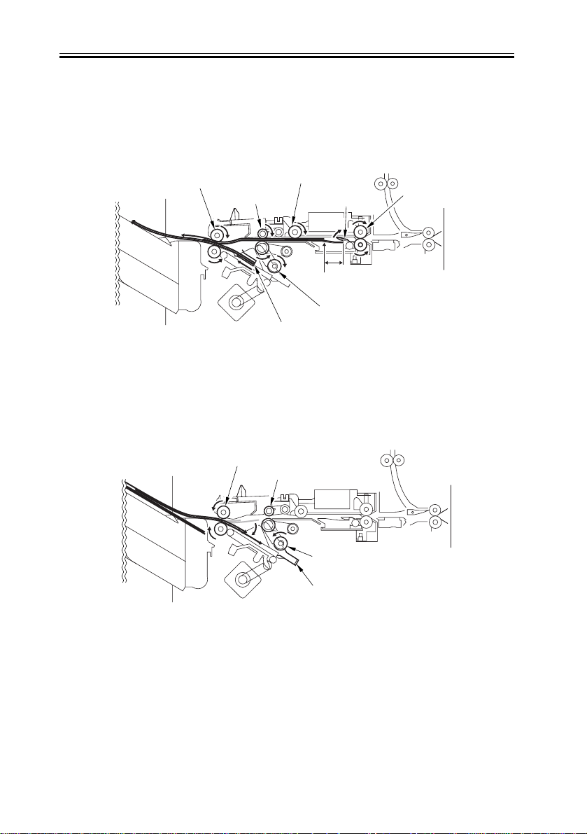
3) The first delivery roller descends and works together with the stack delivery roller to
deliver the 1st and 2nd paper toward the processing tray. At the same time, the stack in the
processing tray is delivered toward the delivery tray by the return roller and rear end assist
guide.
Stack ejection roller
1st delivery roller
Rear end assist guide
Buffer roller
Buffer guide
20mm
Switch back point
Return roller
Feed roller
F-2-11
4) When the stack in the processing tray is delivered to the delivery tray and the rear end of
the 1st and 2nd paper exits the 1st delivery roller, the 1st and 2nd paper are delivered toward
the processing tray by the stack delivery roller and return roller.
Stack ejection roller
1st delivery roller
Return roller
2-10
Processing tray
F-2-12
Chapter 2
5) The 1st and 2nd paper delivered to the processing tray are aligned and then delivered to
the delivery tray.
Stack ejection roller
Return roller
Rear end assist guide
F-2-13
<Escape Ejection (Destination: Escape Tray)>
When the escape tray is specified as the destination of paper ejection in the non-sort mode,
the paper delivered from the host machine to the finisher is rerouted to the path shown
below by the escape inlet flapper and ejected to the escape tray.
Escape delivery
roller
Escape feed
roller
F-2-14
Inlet roller
Escape inlet
flapper
2-11
Chapter 2
2.3 Intermediate Process Tray Assembly
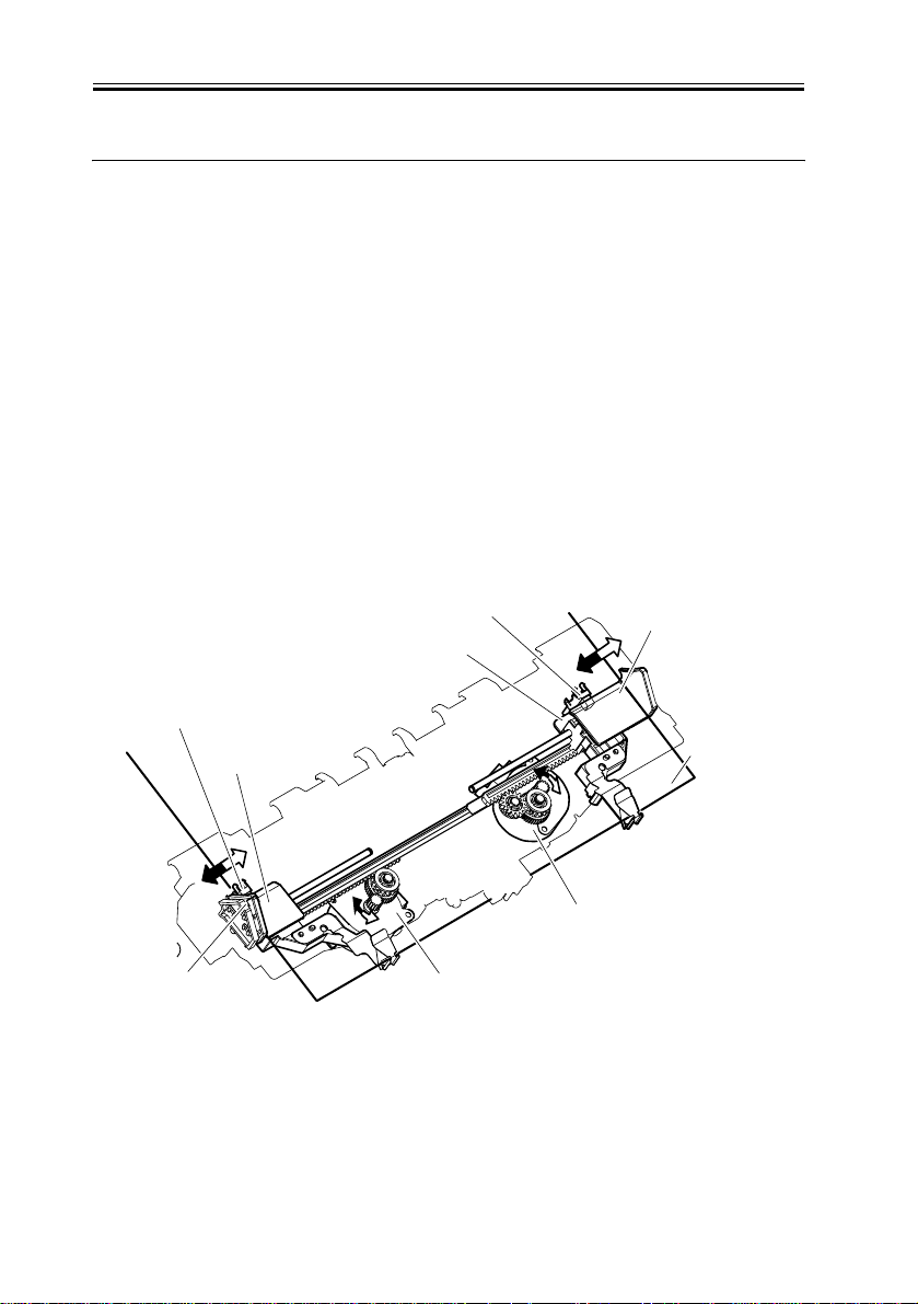
2.3.1 Stack Job Offset
0009-2513
Job offset operation offsets paper stack to the front or rear when ejecting to sort the paper
stack.
The forward/backward movement of the copy delivered to the processing tray is controlled
by the front aligning plate and rear aligning plate.
The aligned copies are stapled or ejected according to the signal from the host machine.
When the power is turned on, the finisher controller PCB drives the aligning plate front
motor (M103) and aligning plate rear motor (M104) to return the two aligning plates to
home position.
The name and function of motors and sensors used by the stack job offset function are
shown below.
Rear aligning plate
home position sensor (PI107)
Light-shielding plate
Front aligning plate
home position sensor (PI106)
Aligning plate
(front)
Aligning plate (rear)
Paper
(FRONT
Light-shielding plate
2-12
Rear aligning plate motor (M104)
Front aligning plate motor (M103)
F-2-15
 Loading...