

Page 1

Digital Cinema Camera
Instruction Manual
PUB. DIE-0549-000
Firmware ver. 1.0.0.1 (
)
ver. 1.0.1.1 (
)
Page 2

Safety Instructions
Be sure to read these instructions in order to operate the product safely. Follow these instructions to prevent
injury or harm to the operator of the product or others.
WARNING
Denotes the risk of serious injury or death.
• Stop using the product in any case of unusual circumstances such as the presence of smoke or a strange
2
smell.
• Do not touch any exposed internal parts.
• Do not get the product wet. Do not insert foreign objects or liquids into the product.
• Do not touch the product connected to a power outlet during lightning storms. This may cause electric shock.
• Do not disassemble or modify the product.
• Do not expose the product to strong shocks or vibration.
• Use only power sources specified in this instruction manual
• Observe the following instructions when using a battery charger or AC adapter.
- Do not touch the battery charger or AC adapter connected to a power outlet during lightning storms.
- Do not use the product if the power plug is not fully inserted into the power outlet.
- Do not unplug the product by pulling the power cord.
- Do not plug in or unplug the product with wet hands.
- Do not place heavy objects on the power cord. Do not damage, break or modify the power cord.
- Do not leave the product connected to a power source for long periods of time.
- Do not expose the power plug and terminals to dirt or let them come into contact with metallic pins or other
metal objects.
- Do not charge batteries/battery packs at temperatures outside the range of 0 - 40 °C (32 - 104 °F).
• Observe the following instructions when using commercially available batteries or provided battery packs.
- Do not use leaking batteries/battery packs.
If a battery/battery pack leaks and the material contacts your skin or clothing, flush the exposed area
thoroughly with running water. In case of eye contact, flush thoroughly with copious amounts of clean
running water and seek immediate medical assistance.
- Use batteries/battery packs only with their specified product.
- Do not heat batteries/battery packs or expose them to fire.
- Do not charge batteries/battery packs using non-authorized battery chargers.
- Do not expose the terminals to dirt or let them come into contact with metallic pins or other metal objects.
- Keep batteries out of the reach of children.
- When disposing of batteries/battery packs, insulate the terminals with tape or other means.
• Do not shoot the sun directly or point a lens or a camera/camcorder with a lens attached at the sun. Even
when the sun does not appear on the screen or is behind the subject, the lens may concentrate the sunlight
and cause a malfunction or fire.
• Do not leave a lens or a camera/camcorder with a lens attached, exposed without the lens cap attached. The
lens may concentrate the light and cause fire.
• Do not leave the lens exposed without the lens cap attached.
• Do not wrap the product in cloth or other materials when in use or shortly after use when the product is still
warm in temperature.
• Do not allow the product to maintain contact with the same area of skin for extended periods of time during
use. This may result in low-temperature contact burns, including skin redness and blistering, even if the
product does not feel hot. The use of a tripod or similar equipment is recommended when using the product in
hot places and for people with circulation problems or less sensitive skin.
• Keep the product out of the reach of young children.
• A strap wrapped around a person’s neck may result in strangulation.
• Periodically remove any dust buildup from the power plug and power outlet using a dry cloth.
• Follow any indications to turn off the product in places where its use is forbidden. Not doing so may cause
other equipment to malfunction due to the effect of electromagnetic waves and even result in accidents.
• Before installing, be sure the surface is capable of supporting the total weight of the camera and connected
devices, and sufficiently reinforce the surface if necessary.
for use with the product.
Page 3

CAUTIONS
Follow the cautions below. Otherwise physical injury or property damage may result.
• Strap is intended for use on the body only. Hanging the strap with any product attached on a hook or other
object may damage the product. Also, do not shake the product or expose the product to strong impacts.
This may cause injury or damage to the product.
• Do not leave the product in places exposed to extremely high or low temperatures. The product may become
extremely hot/cold and cause burns or injury when touched.
• Only mount the product on a tripod that is sufficiently sturdy.
• Do not look at the screen for prolonged periods of time. This may induce symptoms similar to motion
sickness. In such a case, stop using the product immediately and rest for a while before resuming use.
3
Page 4

4
Page 5

Table of Contents
5
Safety Instructions 2
1. Introduction 9
About this Manual 9
Conventions Used in this Manual 9
Supplied Accessories 10
Before Using the Camera 11
Names of Parts 12
Camera 12
LM-V2 LCD Monitor 18
LA-V2 LCD Attachment Unit 19
GR-V1 Camera Grip 20
Handle Unit 21
4K and Higher Resolutions: Workflow
Overview 22
Color Grading with the ACES Workflow 23
2. Preparations 25
Preparing the Power Supply 25
Using a Battery Pack 25
Using the DC IN 12V Terminal 27
Preparing the Handle Unit and LCD Monitor 29
Attaching the Handle Unit 29
Attaching the LCD Monitor 29
Adjusting the LCD Monitor 31
Removing the LCD Monitor and LCD Attachment
Unit 32
Date, Time and Language Settings 33
Setting the Date and Time 33
Changing the Language 33
Using the Menus 34
Selecting an Option from the Menu 34
Using the Customized Menus (My Menu) 35
Preparing the Lens 37
Attaching an EF Lens 37
Updating the Firmware of an EF Lens 38
In-Camera Lens Correction 39
Preparing Other Accessories 40
Examples of Camera Configurations 40
Removing and Attaching the Camera Grip 41
Attaching the Microphone Holder 42
Preparing Recording Media 43
Compatible Recording Media 43
Inserting a CFexpress Card 44
Removing a CFexpress Card 44
Inserting and Removing an SD Card 45
Initializing Recording Media 46
Switching Between CFexpress Card Slots 46
Relay Recording and Double Slot Recording 47
Checking the Remaining Recording Time on a
Card 47
Recovering Clips 48
Adjusting the Black Balance 49
3. Recording 51
Recording Video and Photos 51
Recording 51
Onscreen Displays 53
Selecting the Onscreen Display Level 57
Setting a Card’s Volume Label 59
Setting the Clip File Name 59
Using the Fan 61
Video Configuration: Video Format, Sensor Mode,
System Frequency, Resolution and Frame
Rate 62
Selecting the Sensor Mode 62
Selecting the Main Recording Format 62
Selecting the System Frequency 62
Selecting the Resolution and Color Sampling
Settings 62
Selecting the Frame Rate 63
Selecting the Bit Rate 63
Proxy Clips (Simultaneous Recording) 67
Direct Setting Mode (FUNC Button) 68
Using the Direct Setting Mode 68
Shutter Speed 69
Changing the Shutter Speed Mode and Value 70
ISO Speed/Gain 71
Changing the ISO Speed or Gain Value 72
Using the Control Dial 72
ND Filter 73
Page 6

6
Aperture 74
Manual Aperture: Changing the Aperture
Value 74
Using the Control Dial 75
Momentary Automatic Aperture - Push Auto
Iris 76
Automatic Aperture 76
Exposure Compensation - AE Shift 77
Light Metering Mode 77
White Balance 78
Custom White Balance 78
Color Temperature/Preset White Balance 79
Auto White Balance (AWB) 80
Focus 81
Manual Focus 82
One-Shot AF 85
AF-Boosted MF 85
Continuous AF 86
Changing the AF Frame Size and Position 87
Face Detection 88
Tracking a Specific Subject 89
Image Stabilization 90
Zoom 91
Onscreen Markers, Zebra Patterns and False
Color 92
Displaying Onscreen Markers 92
Displaying Zebra Patterns 94
Displaying False Color 94
Setting the Time Code 95
Selecting the Time Code Mode 95
Selecting Drop or Non-Drop Frame 96
Setting the User Bit 97
Synchronizing with an External Device 98
Connecting an External Device 98
Time Code Signal Input 98
Time Code Signal Output 99
Reference Video Signal Input (Genlock
Synchronization) 99
Reference Video Signal Output 100
Recording Audio 101
Audio Settings and Recorded Audio
Channels 101
Connecting an External Microphone or External
Audio Input Source to the Camera 104
Setting the Audio Input Type for the INPUT 1/
INPUT 2 Terminals 105
Selecting the Audio Input Source for Audio
Channels 105
Adjusting the Audio Recording Level 106
Advanced Audio Input Settings 107
Monitoring the Audio with Headphones 108
Colors Bars/Audio Reference Signal 109
Color Bars 109
Audio Reference Signal 109
Video Scopes 110
Displaying a Video Scope 110
Configuring the Waveform Monitor 110
Configuring the Vectorscope 111
Adding Marks to Clips in CAMERA Mode 112
Adding a Shot Mark while Recording 112
Adding an $ Mark or % Mark to the Last Clip
Recorded 112
Using Metadata 113
Setting a User Memo Created with Canon XF
Utility 113
Entering Slate Information About the
Recording 114
Reviewing a Recording 115
Special Recording Modes 116
Slow & Fast Motion Recording 116
Pre-recording 119
Using Anamorphic Lenses 120
Using the Optional RC-V100 Remote
Controller 121
Page 7

7
4. Customization 123
Assignable Buttons 123
Custom Picture Settings 127
Selecting Custom Picture Files 127
Preset Picture Settings 127
Renaming Custom Picture Files 128
Protecting Custom Picture Files 128
Resetting Custom Picture Files 128
Editing a Custom Picture File’s Settings 129
Copying Custom Picture Files 129
Embedding the Custom Picture File in Clips 129
Available Custom Picture Settings 130
Saving and Loading Menu Settings 134
Saving Menu Settings 134
Loading Menu Settings 134
5. Playback 135
Playback 135
Clip Index Screen 135
Playing Back Recordings 137
Onscreen Displays During Clip Playback 138
Clip Playback Controls 139
Adjusting the Volume 139
Clip/Photo Operations 140
Displaying Clip Information 140
Adding $ Marks or % Marks 141
Deleting $ Marks or % Marks 142
Adding Shot Marks 142
Deleting All the Shot Marks from a Clip 142
Deleting Clips and Photos 142
Deleting the User Memo and GPS Information from
a Clip 143
6. External Connections 145
Video Output Configuration 145
SDI OUT Terminal Video Output Configuration
(Recording/Playback) 145
MON. Terminal / HDMI OUT Terminal Video
Output Configuration
(Recording/Playback) 146
Connecting to an External Monitor or
Recorder 147
Using the SDI OUT Terminal 147
Using the MON. Terminal 148
Using the HDMI OUT Terminal 148
Selecting the Video Output’s Scan Mode 149
Superimposing Onscreen Displays on Video
Outputs 149
Changing the Opacity Level of Onscreen
Displays 149
Selecting the Output Range 150
Applying a LUT to Video Outputs 151
Adjusting the Color Quality for HLG Output 152
Adjusting the Gain Difference between HDR and
SDR 152
User LUTs 153
Audio Output 155
Working with Clips on a Computer 156
Saving XF-AVC Clips 156
Developing RAW Clips 156
7. Network Functions 157
About the Network Functions 157
Using Networks 158
Using a Wi-Fi Network 158
Using a Wired (Ethernet) Network 159
Configuring Connection Settings 160
Adding a New Connection Setting Using the
Wizard 161
Function Settings 162
Other Connection Methods 165
Checking and Changing Connection
Settings 167
Configuring the Camera’s IP Address
Manually 169
Checking and Changing Communication Settings/
Function Settings 169
Configuring IPv6 Settings 171
Reading a Root Certificate for FTPS Transfer 171
802.1X Authentication 172
Giving a Nickname to the Camera 172
Checking the Network’s Status 173
FTP File Transfer 174
Transferring a Single Clip 174
Transferring All Clips 174
Page 8

8
IP Streaming 175
Browser Remote: Controlling the Camera from a
Network Device 177
Starting Browser Remote 177
Using Browser Remote 179
8. Additional Information 185
Menu Options 185
Displaying the Status Screens 198
Troubleshooting 208
List of Messages 214
Handling Precautions 219
Maintenance/Others 222
Optional Accessories 223
Specifications 225
Reference Tables 231
Approximate Recording Time on a Card 231
Charging Times 231
Approximate Usage Times with a Fully Charged
Battery Pack 232
Appendix: Compatible Lenses and Functions 233
Appendix: Camera Dimensions 236
Index 243
Page 9

Introduction
1
About this Manual
Thank you for purchasing the Canon EOS C300 Mark III / EOS C500 Mark II. Please read this manual carefully
before you use the camera and retain it for future reference. Should the camera fail to operate correctly, refer to
Troubleshooting
Conventions Used in this Manual
• IMPORTANT: Precautions related to the camera’s operation.
• NOTES: Additional topics that complement the basic operating procedures.
• A: Reference page number.
• : Text that applies only to the model shown in the icon.
• The following terms are used in this manual.
- “Screen” refers to the LCD screen on the supplied LCD monitor.
- “LCD monitor” refers to the supplied LM-V2 LCD Monitor.
- “LCD attachment unit” refers to the supplied LA-V2 LCD Attachment Unit.
- “Camera grip” refers to the supplied GR-V1 Camera Grip.
- “Viewfinder” refers to the optional EVF-V50 OLED Electronic Viewfinder.
- “Battery pack” refers to a Canon BP-A30 Battery Pack (optional) or BP-A60 Battery Pack (supplied).
- “AC adapter” refers to a commercially available power adapter.
- “SD card” refers to an SD, SDHC or SDXC memory card.
- “Recording media” or “card” alone, not specified: refers collectively to CFexpress cards and SD cards.
- “CAMERA mode”: operating mode for making recordings (shooting mode).
“MEDIA mode”: operating mode for playing back and managing recordings (playback mode).
- “Access indicator”: when not specified, refers collectively to the SD CARD and CFexpress access
indicators.
- “RAW” refers to the data recorded using Cinema RAW Light.
• Unless indicated otherwise, illustrations in the manual show the Canon EOS C500 Mark II camera with a
Canon EF 50mm f/1.4 USM lens attached.
• Photographs in the manual are simulated pictures taken with a still camera.
• Unless indicated otherwise, screenshots in the manual are from the EOS C500 Mark II camera. Some
screenshots have been altered to make them easier to read. Furthermore, screenshots used are from a
product in development and may differ slightly from the actual screens due to product enhancement.
(A 208).
9
Page 10
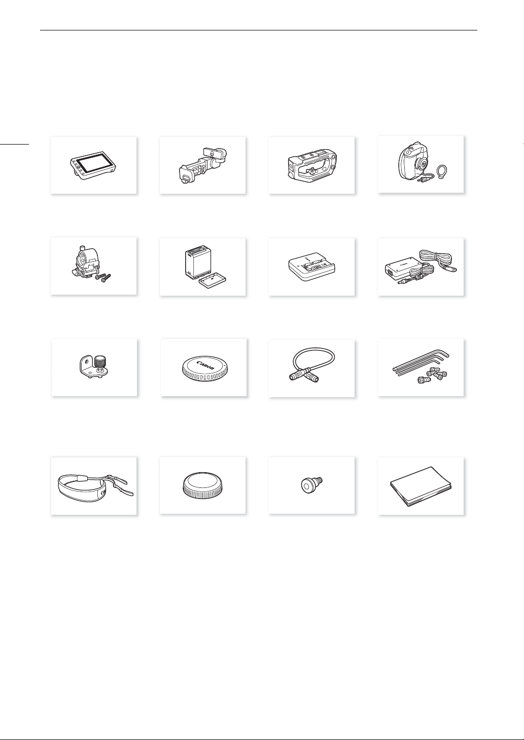
Supplied Accessories
Supplied Accessories
The following accessories are supplied with the camera.
10
LM-V2 LCD Monitor LA-V2 LCD Attachment Unit Handle Unit GR-V1 Camera Grip*
Microphone Holder
(incl. M4 fixation bolts, x2)
Expansion System Attachment
Bracket
BP-A60 Battery Pack
(incl. terminal cover)
Body Cap* UN-5 Unit Cable Hex socket head bolts
CG-A20 Battery Charger CA-CP200 B Compact Power Adapter
(incl. grip attachment ring)
(for the CG-A20; incl. power cord)
(0.64 cm, 1/4" x1, M3 x4)
and hex wrenches
(x3, for 0.64 cm, 1/4" / M4 / M3 bolts)
SS-1200 Shoulder Strap Thumb Rest Tape Measure Hook* Quick Guide
* Comes pre-attached to the camera.
Page 11

Supplied Accessories
IMPORTANT
Before Using the Camera
• Before making important recordings for the first time, make test recordings using the video configuration(s) you
plan to use to check that the camera operates correctly. Should it fail to operate correctly, refer to
Troubleshooting
• Copyright notice: Unauthorized recording of copyrighted materials may infringe on the rights of copyright
owners and be contrary to copyright laws.
• About the LCD screen: The screen is produced using extremely high-precision manufacturing techniques, with
more than 99.99% of the pixels operating to specification. Very rarely, pixels may misfire or light up
permanently. This has no effect on the recorded image and does not constitute a malfunction.
• CFexpress cards can become hot due to the high operating temperature inside the camera. Removing a
CFexpress card immediately after using it for recording may cause burns or cause you to drop the card,
resulting in damage to the card.
• Observe the following precautions while an access indicator (A 44, 45) is illuminated or flashing in red. Failing
to do so may result in permanent data loss.
- Do not turn off the camera and do not remove the battery or other power source.
- Do not open the card compartment cover.
(A 208).
11
Page 12
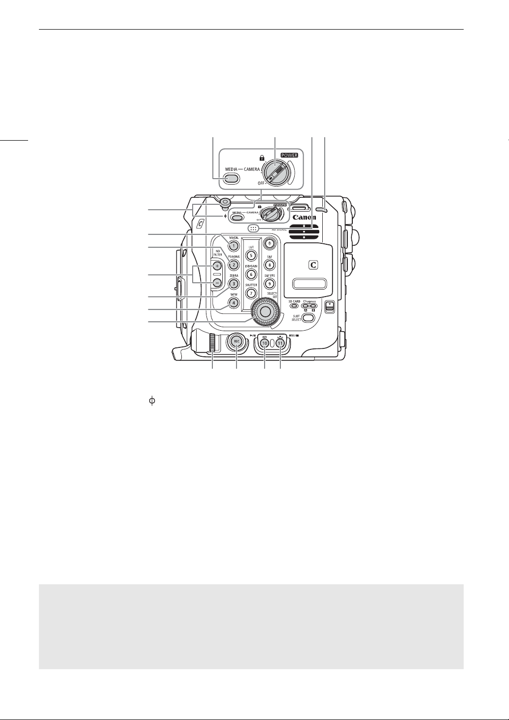
Names of Parts
1 Tape measure hook and focal plane mark
2 MAGN. (magnification) button (A 84)/
Assignable button Camera 1*
3 PEAKING button (A 84)/
Assignable button Camera 2*
4 ND FILTER +/– buttons (A 73)
5 ZEBRA button (A 94)/
Assignable button Camera 3*
6 WFM (video scope) button (A 110)/
Assignable button Camera 4*
7 SELECT dial/SET button (A 34)
8 MEDIA button (A 135)
When the camera is on, press to toggle the
camera between CAMERA mode (shooting) and
MEDIA mode (playback).
9
Q
switch
Set to CAMERA to turn on the camera or to OFF
to turn it off.
10 Built-in monaural microphone (A 105)
11 Power indicator/Rear tally lamp (A 51)
12 Control dial (A 72, 75)
13 REC (start/stop recording) button (A 51)
14 WB (white balance) button (A 78)/
Assignable button Camera 10*
Ò
(play/pause) button (A 137)
15 Å (white balance adjustment) button (A 78)/
Assignable button Camera 11*/
INDEX button (A 136)/
Ñ
(stop) button (A 137)
Names of Parts
Camera
12
109811
1
2
3
4
5
6
7
12 13 14 15
* See
Assignable Buttons
Locking the camera’s controls (key lock)
You can set the
preventing settings from being changed due to inadvertently pressing one of the buttons. Set the
switch back to CAMERA to reactivate the controls.
When the camera’s controls are locked, you can still operate the camera using an optional RC-V100 Remote
Controller or the Browser Remote application.
* In CAMERA mode, REC buttons are not locked by default but you can choose to lock them too (A 195).
(A 123)
Q
switch to C (key lock) to lock all the camera’s buttons and switches. This is useful in
Q
Page 13
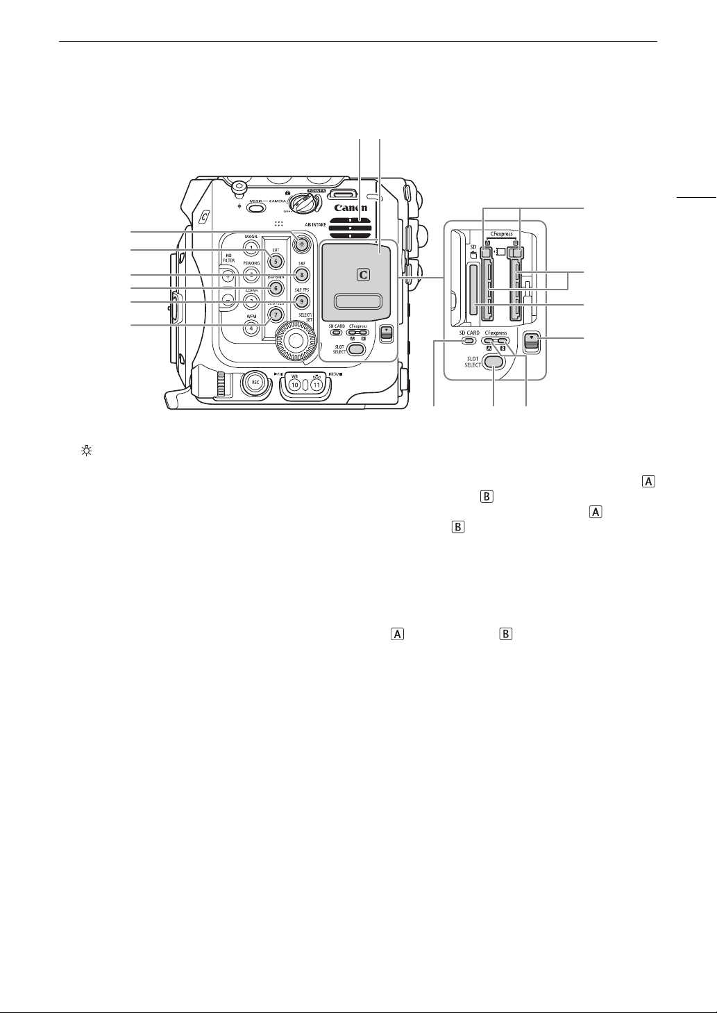
Names of Parts
1
2
3
5
6
4
78
9
10
11
12
13 14 15
Turns on/off the illumination of the buttons on the
camera’s left and back sides. This is convenient
for night time or black-out operation.
Assignable button Camera 5*
(A 116)/Assignable button Camera 8*
Assignable button Camera 6*
(A 116)/Assignable button Camera 9*
Assignable button Camera 7*
7 Air intake vent (A 61)
8 Card compartment cover (A 44, 45)
9 CFexpress card release buttons: for CFexpress
(left), CFexpress (right), (A 44)
10 CFexpress card slots: for CFexpress (left),
CFexpress (right), (A 44)
11 SD card slot (A 45)
12 Card compartment cover switch
13 SD CARD access indicator (A 45)
14 SLOT SELECT (CFexpress card selection) button
(A 46, 136)
15 CFexpress card access indicators: for CFexpress
(left), CFexpress (right), (A 44)
13
* See
Assignable Buttons
(A 123)
Page 14
14
1
3
2
4
5
6
7
8
9
10 11 12
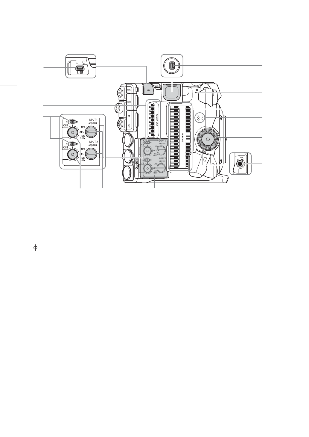
1USB terminal
For connecting the optional GP-E2 GPS Receiver.
2 Exhaust ventilation outlet (A 61)
3 Audio level switches for CH1 (top) and CH2
(bottom) (A 106)
4 System expansion terminal
5 Focal plane mark
6 Air intake vent (A 61)
7 Speaker (A 139)
8 Camera grip attachment thread/Rosette (A 41)
Compliant with ARRI rosettes.
9 GRIP (camera grip connection) terminal (A 41)
10 Audio level dials for CH1 (top) and CH2 (bottom)
(A 106)
11 INPUT 1 (top) / INPUT 2 (bottom) switches
(audio source selection, A 105)
12 Cover for audio controls
Names of Parts
Page 15
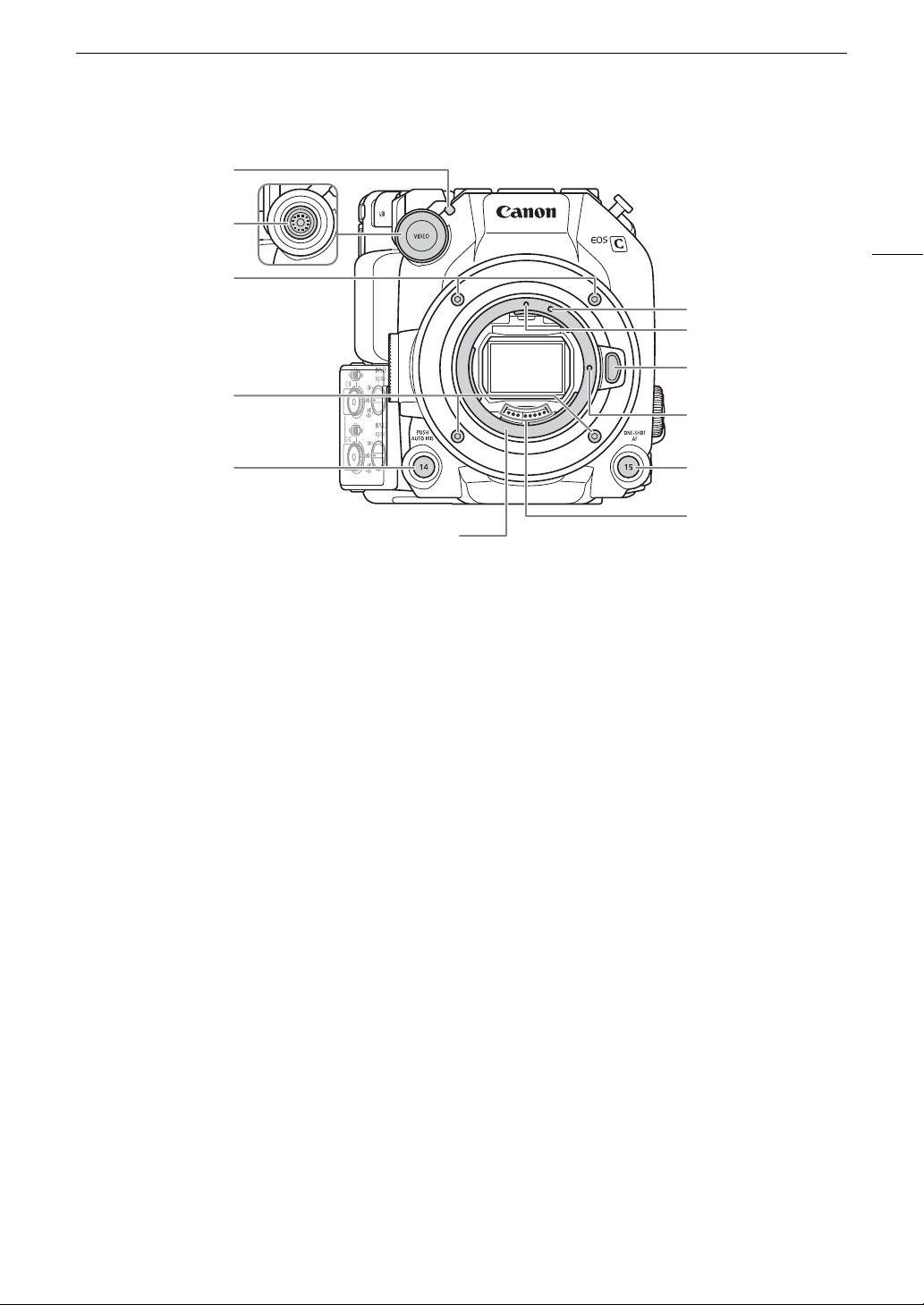
Names of Parts
EF lens mount
1Front tally lamp (A 51)
2VIDEO terminal (A 29)
3 Lens mount fixation bolts
4 PUSH AUTO IRIS (momentary automatic aperture)
button (A 76)/
Assignable button Camera 14 (A 123)
5 EF-S lens mount index (A 37)
6 EF lens mount index (A 37)
7 Lens release button (A 37)
8EF lens lock pin
9 ONE-SHOT AF (focus automatically once) button
(A 85)/
Assignable button Camera 15 (A 123)
10 EF lens contacts (A 37)
1
2
15
3
5
6
7
3
8
4
9
10
Page 16
16
NOTES
1
2
3
4
5
6
7
8
9
10
11
12
13
14
15
16
18
19
20
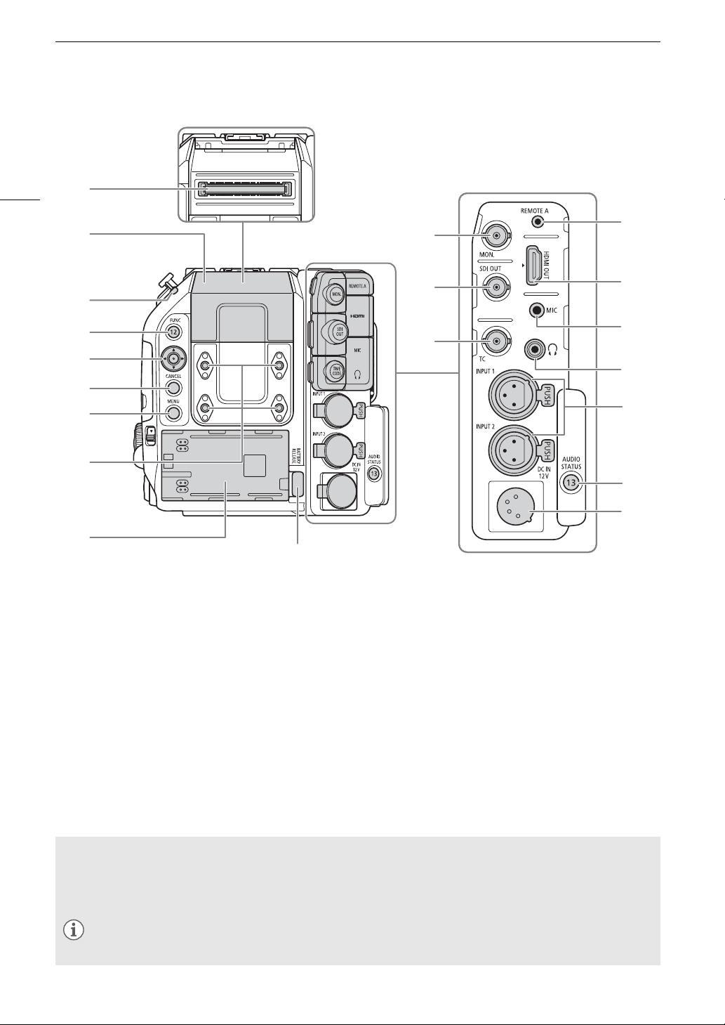
17
1 Expansion unit connector
For connecting the optional EVF-V50 OLED
Electronic Viewfinder, EU-V1 Expansion Unit 1 or
EU-V2 Expansion Unit 2.
2 Expansion unit connector cover
3 Power indicator/Rear tally lamp (A 51)
4 FUNC (main functions) button (A 68)/
Assignable button Camera 12 (A 123)
5 Joystick (A 34)
6 CANCEL button (A 34)
7 MENU button (A 34, 123)
8 Screw holes for M4 bolts (7.5 mm (0.30 in.) deep,
x4)
9 Battery compartment (A 26)
10 MON. terminal (A 147, 148)
11 SDI OUT terminal (A 147)
12 TIME CODE terminal (A 98, 99)
13 REMOTE A terminal (A 121)
For connecting the optional RC-V100 Remote
Controller or commercially available remote
controllers.
14 HDMI OUT terminal (A 147, 148)
15 MIC (microphone) terminal (A 104)
16
×
(headphone) terminal (A 108)
17 INPUT terminals (XLR): INPUT 1 (top), INPUT 2
(bottom) (A 104)
18 AUDIO STATUS (display the [¡ Audio Setup]
status screens) button (A 202)/
Assignable button Camera 13 (A 123)
19 DC IN 12V terminal (A 27)
20 BATTERY RELEASE button (A 26)
Names of Parts
Removing and attaching the terminal covers
You can remove the covers of the camera’s terminals to access them more easily. To remove a terminal’s
cover, open the cover and gently pull it straight out. To attach back the terminal cover, insert the connecting
strip into the opening.
• If the connecting strip is difficult to grasp, use a pair of tweezers or similar tool.
Page 17
Names of Parts
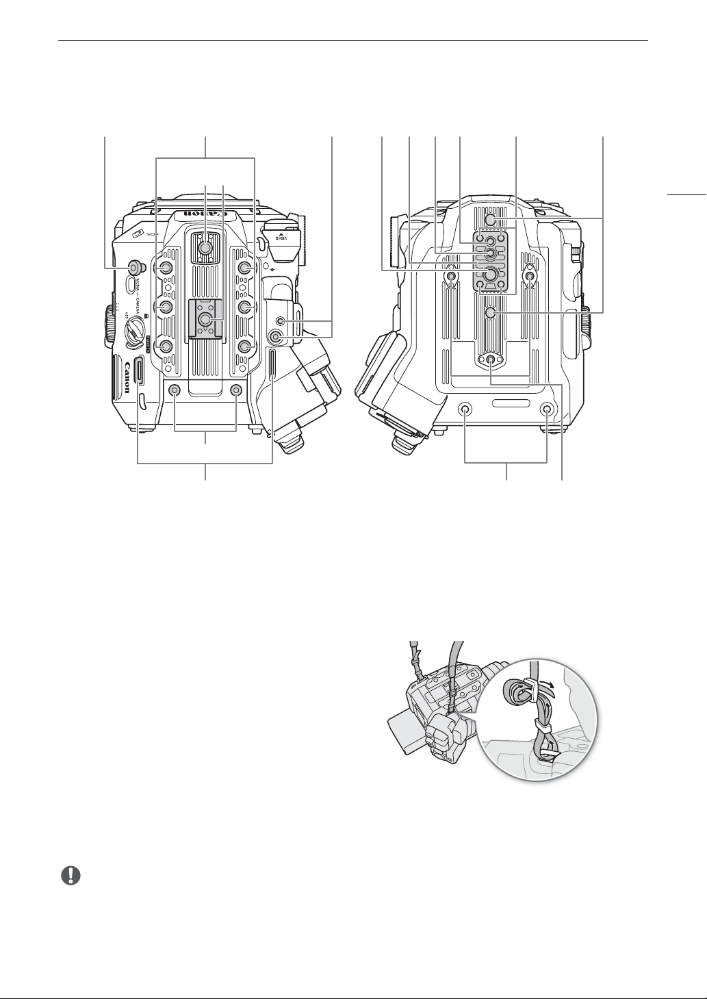
IMPORTANT
1 Tape measure hook
Use the hook to accurately measure the distance
from the focal plane.
2 Screw holes for 1/4"-20 mounting screws
(9 mm (0.35 in.) deep, x6)
3 Top accessory mount with socket for 1/4"-20
mounting screws
(6.7 mm (0.26 in.) deep)
4 Accessory shoe with socket for 1/4"-20 mounting
screws (6.7 mm (0.26 in.) deep)/
Handle attachment unit (A 29)
5 Socket for the expansion system attachment
bracket
6 Screw hole for 3/8"-16 mounting screws
(10 mm (0.39 in.) deep)
7 TB-1 Tripod Base
8 Socket for tripod’s anti-rotation pin
(5.5 mm (0.22 in.) deep)
For tripods with 3/8"-16 mounting screws.
9 Screw hole for tripods with 1/4"-20 mounting
screws (7 mm (0.28 in.) deep)
10 Tripod base screws
11 Sockets for tripod’s anti-rotation pin
(5 mm (0.20 in.) deep, x2)
For tripods with 1/4"-20 mounting screws.
12 M4 screws for expansion unit connector cover
13 Strap mounts
Pass the ends of the supplied shoulder strap
through the strap mounts and adjust the length of
the strap.
14 Expansion unit fixation screw holes (M4, x2)
15 Screw holes for tripod reinforcements and
accessories with 1/4"-20 mounting screws
(7.5 mm (0.30 in.) deep, x3)
1 2 5 7 8 9 10 11
43
12
13
6
14 15
17
• Do not use tripods and other accessories with mounting screws exceeding the depth of the screw holes on
the camera as this may damage the camera.
• Mounting the camera on a tripod using only one of the 1/4"-20 screw holes for tripod reinforcement may
damage the camera.
Page 18
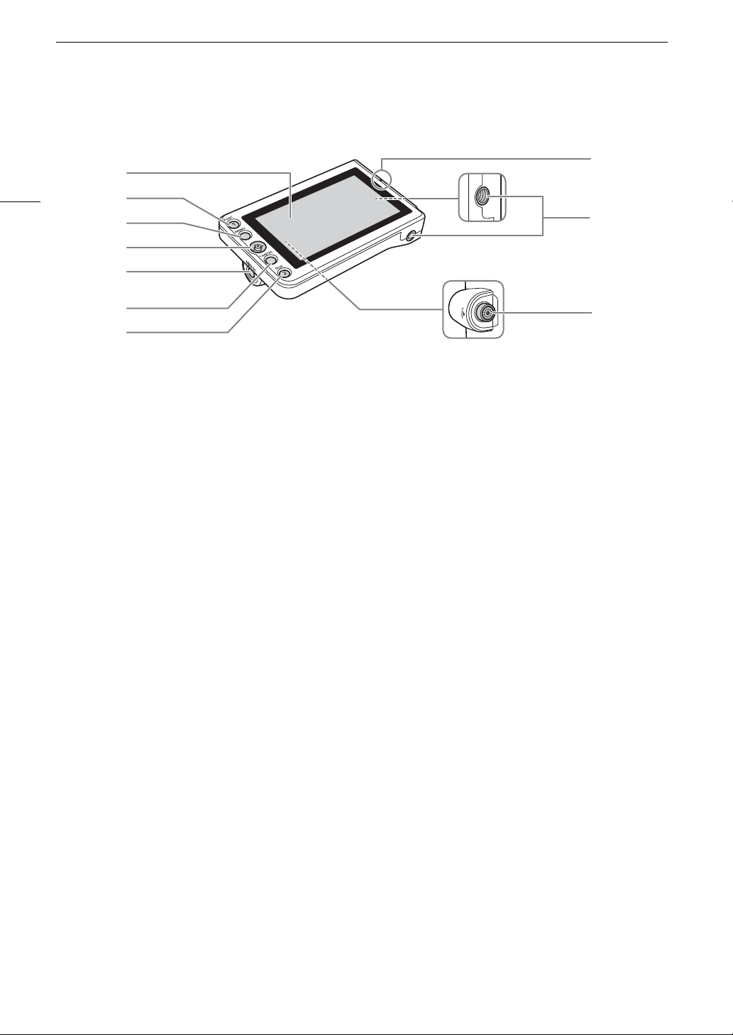
Names of Parts
1
2
3
4
5
6
7
8
9
10
1 LCD panel with touch screen (A 29, 31)
2 FUNC (main functions) button (A 68)/
Assignable button LCD LM-V1/V2 1 (A 123)
3 MENU button (A 34, 123)
4 Joystick (A 34)
5 MIRROR (invert the displayed image) button
(A 32)
6 CANCEL button (A 34)
7 DISP (display) button (A 53, 57)/
Assignable button LCD LM-V1/V2 2 (A 123)
8 LCD monitor’s position alignment mark Í (A 29)
9 Screw holes for 1/4"-20 screws
(11.2 mm (0.44 in.) deep, x2)
10 VIDEO terminal (A 29)
LM-V2 LCD Monitor
18
Page 19
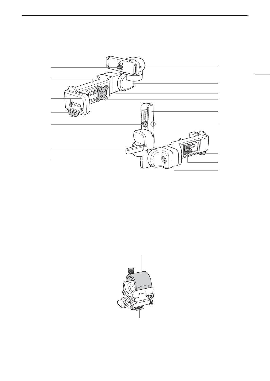
LA-V2 LCD Attachment Unit (A 29)
1
7
5
9
8
4
8
11
10
12
2
3
4
1
6
5
1 LCD monitor fixation bolt
2 Base 1
3 Sockets for the microphone holder (A 42)
4 Cable clamp
5Pivot A
6 Base 2 fixation bolt
7Pivot B
8Base 2
9 Locking knob
10 LCD monitor mount
11 LCD monitor’s position alignment mark Í
12 Attachment mount
1 Microphone lock screw
2 Microphone holder
3 Microphone cable clamp
Names of Parts
19
Microphone Holder (A 42, 104)
132
Page 20
Names of Parts
1
4
5
6
7
8
9
10
2
3
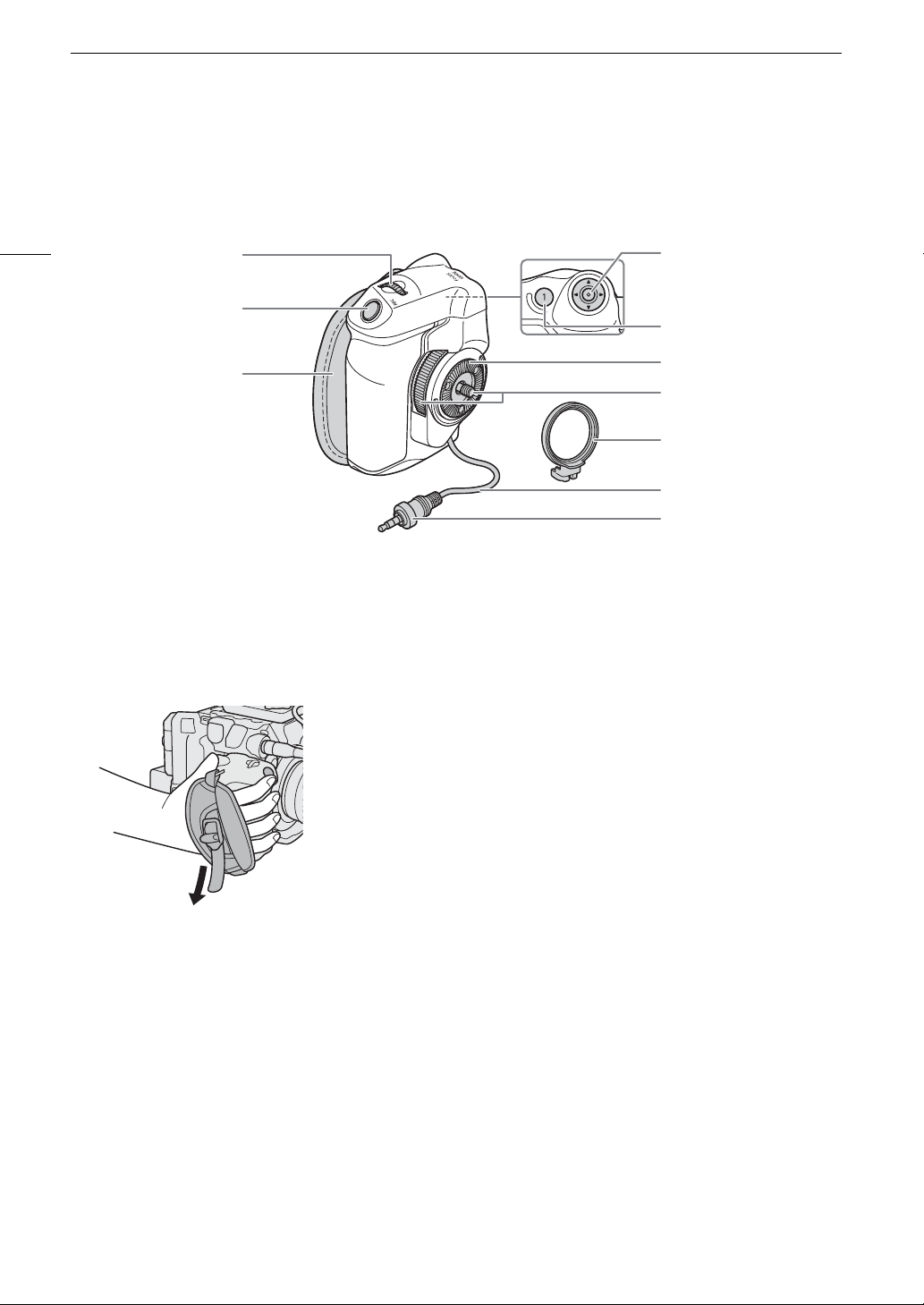
1 Control dial (A 72, 75)
2 REC (start/stop recording) button (A 51)
3 Grip belt
Adjust the grip belt so that you can reach the REC
button on the camera grip with your index finger
but still have a comfortable but secure grip.
4 Joystick (A 34)
5 FOCUS GUIDE button (A 83)/
Assignable button Camera Grip 1 (A 123)
6 Rosette
Compliant with ARRI rosettes.
7 Locking screw
8 Grip attachment ring
9 Grip connection cable
10 Connection plug
GR-V1 Camera Grip (A 41)
At the time of purchase, the camera grip is pre-attached to the camera.
20
Page 21
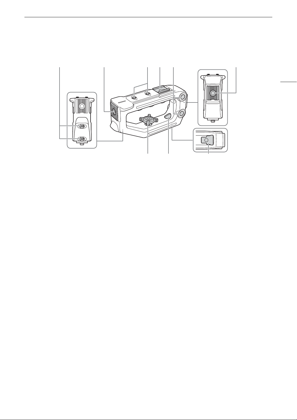
Handle Unit (A 29)
12134 5
687
1 Screw holes for 1/4"-20 screws
(6 mm (0.24 in.) deep, x4)
2 Front accessory mount with socket for 1/4"-20
screws (8.8 mm (0.35 in.) deep)
3 Top accessory shoe
4 Through-holes ( 8.8 mm (0.35 in.), distance
center-to-center 35.5 mm (1.4 in.))
5 Rear accessory mount with socket for 1/4"-20
screws (8.8 mm (0.35 in.) deep)
6 Locking knob
7 Rear mounting hole (through-hole)
8Mounting base
Names of Parts
21
Page 22
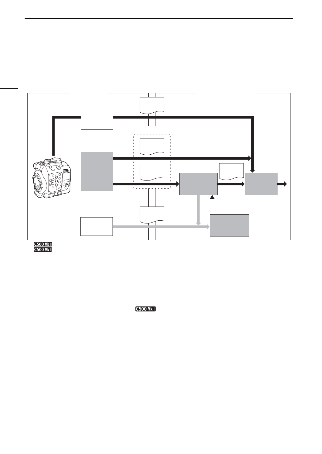
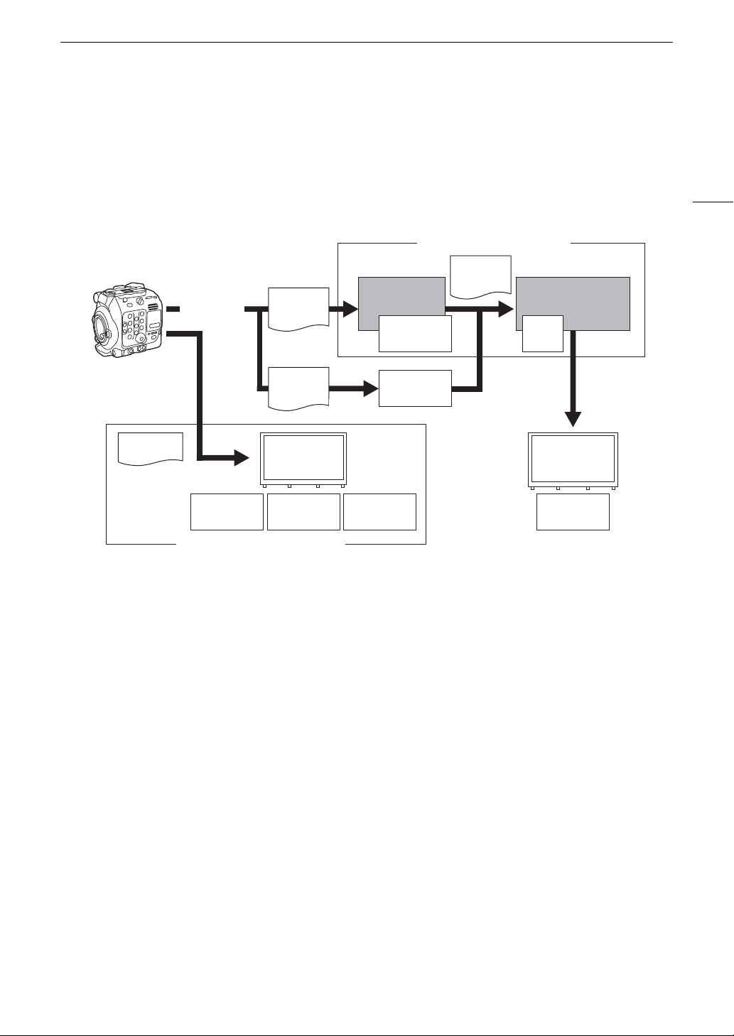
4K and Higher Resolutions: Workflow Overview
Recording Post-production
SDI OUT /
HDMI OUT
terminal
output
SD card
XF-AVC
data
EDL
NLE software
2K recording
(XF-AVC)
Cinema
RAW
Development
Color
grading
External
recorder
Full-quality
data
RAW
data
1
only.
2
2K proxy clip recording on the SD card is not available simultaneously with 4K XF-AVC recording.
4K recording
5.9K
1
/4K recording (RAW),
4K recording (XF-AVC
2
)
CFexpress
card
Full-quality
data
Shooting
Proxy
data
Primary clips
Proxy
data
4K and Higher Resolutions: Workflow Overview
The following illustrates the typical workflow for 5.9K/4K recording with the camera. 5.9K recording is available
only with the EOS C500 Mark II model.
22
Shoot in 5.9K/4K mode (A 62).
You can record 5.9K/4K RAW or 4K YCbCr 4:2:2 data on a CFexpress card in the camera, or record
While recording 5.9K/4K primary clips ( RAW clips only), you can simultaneously record 2K
After recording, develop the 5.9K/4K RAW clips using the Cinema RAW Development software
You can use the 2K proxy clips recorded on the SD card or proxy files generated by Cinema RAW
Perform color grading based on the full-quality data.
4K data using an external recorder connected to the camera’s SDI OUT or HDMI OUT terminal
(A 147).
• Clips other than 5.9K/4K RAW need no further processing and can be color graded directly (step ).
proxy clips on an SD card.
• The file names of 2K proxy clips (XF-AVC) and 5.9K/4K clips are linked and identical for the most part
(A 156) to generate full-quality data.
(A 59).
• You can also generate proxy data.
Development on NLE software to edit the video offline and create an EDL.
Page 23
4K and Higher Resolutions: Workflow Overview
Cinema RAW
Development
Color grading
Post-production
On-set Color Grading
ACESproxy
Inverse log
ASC-CDL
Output
Trans for m
SDI OUT /
MON. /
HDMI OUT
terminal output
RAW
data
OpenEXR
(ACES 1.0)
Input
Trans form
ASC-
CDL
Output
Transf orm
CFexpress
card
XF-AVC
data
Input
Trans form
Color Grading with the ACES Workflow
You can perform color grading using ACES2065-1, the color encoding system defined by the Academy of
Motion Picture Arts and Sciences. This workflow allows you to perform on-set color grading* while continuing to
shoot.
* Requires monitors compatible with ASC-CDL and 3D LUT color correction.
23
ACESproxy: ACESproxy video data that is output from the camera’s output terminals when performing
on-set color grading. Select the [ACESproxy] option for the LUT setting, depending on where
the video is to be output (A 151).
Input Transform: Refers to the table used for converting color information of the input device to ACES2065-1
color space.
Output Transform: Refers to the table used for mapping ACES2065-1 color space information to the specific
color information scheme used by the display device.
ASC-CDL: Refers to the list that contains color grading adjustment data. This step requires equipment
compatible with ASC-CDL.
Page 24

4K and Higher Resolutions: Workflow Overview
24
Page 25
Preparations
IMPORTANT
CHARGE
indicator
Compact power adapter
Battery Charger
2
Preparing the Power Supply
You can power the camera using a battery pack or the DC IN 12V terminal. Even when a battery pack is
attached, if a power source is connected to the DC IN 12V terminal, the camera will not draw power from the
battery pack.
Using a Battery Pack
You can power the camera using the supplied BP-A60 Battery Pack or the optional BP-A30 Battery Pack. Both
battery packs are compatible with Intelligent System so you can check the approximate remaining battery usage
time (in minutes) on the screen. For more accurate readings, when using a battery pack for the first time, charge
it fully and then use the camera until the battery pack is completely depleted.
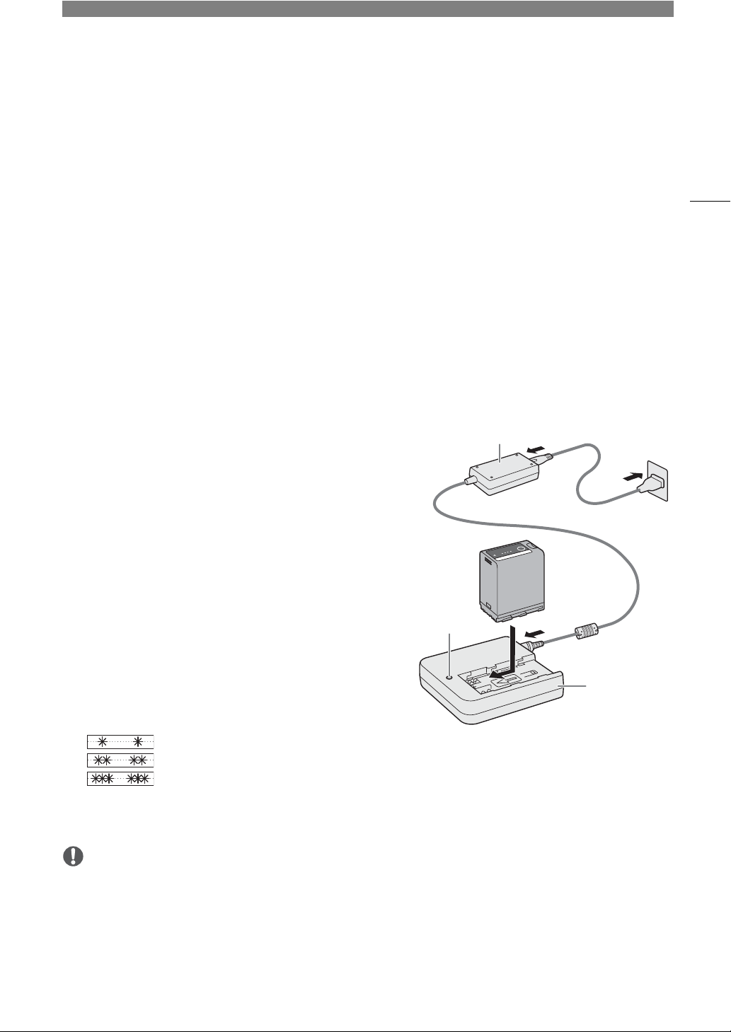
Charging the Battery Pack
Charge battery packs using the supplied CG-A20 Battery
Charger and CA-CP200 B Compact Power Adapter. Before
charging, remove the terminal cover of the battery pack.
1 Connect the compact power adapter to the battery charger
and plug the power cord into a power outlet.
2 Attach the battery pack to the battery charger.
• Press lightly and slide the battery pack in the direction of the
arrow until it clicks.
• The CHARGE indicator starts flashing and also indicates the
battery pack’s approximate charge. The indicator will stay on
when charging has completed.
25
3 Disconnect the compact power adapter from the battery charger and unplug the power cord.
4 Remove the battery pack from the battery charger.
• Do not connect to the battery charger any product that is not expressly recommended for use with this
camera.
• When using the battery charger or compact power adapter, do not fix it permanently to one place as this may
cause a malfunction.
• To prevent equipment breakdowns and excessive heating, do not connect the supplied battery charger or
compact power adapter to voltage converters for overseas travels or special power sources such as those on
aircraft and ships, DC-AC inverters, etc.
approx. 0% to 49%: Flashes once every 2 seconds
approx. 50% to 74%: Flashes twice every 2 seconds
approx. 75% to 99%: Flashes 3 times every 2 seconds
Page 26
Preparing the Power Supply
NOTES
• We recommend charging the battery pack in temperatures between 10 ºC and 30 ºC (50 ºF and 86 ºF).
Outside the temperature range of 0 ºC to 40 ºC (32 ºF to 104 ºF), charging will not start.
• If there is a malfunction with the battery charger, compact power adapter or battery pack, the charge indicator
26
will go out and charging will stop.
• For handling precautions regarding the battery pack, refer to
(A 219).
• For approximate charging times and usage times with a fully charged battery pack, refer to the
Ta bl es
(A 231).
• Charged battery packs continue to discharge naturally. Therefore, charge them on the day of use, or the day
before, to ensure a full charge.
• We recommend that you prepare battery packs to last 2 to 3 times longer than you think you might need.
• Repeatedly charging and completely depleting a battery pack will eventually shorten its battery life. You can
B
check the battery life on the [
then depleting it completely will give you a more accurate reading.
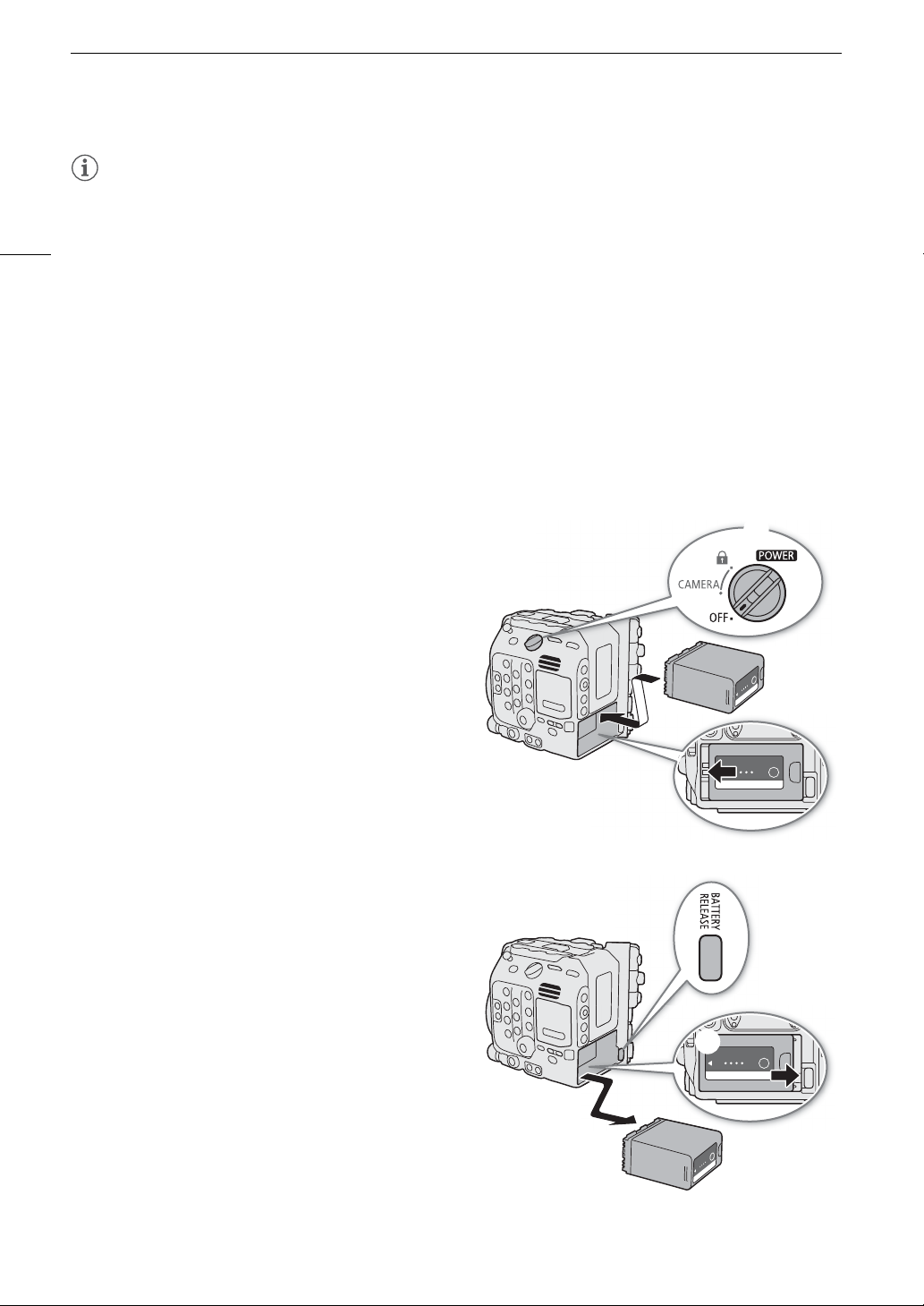
Attaching the Battery Pack
1 Turn off the camera.
2 Insert the battery pack all the way into the compartment
as shown in the illustration and press it gently toward the
left until it clicks.
System Setup] status screen (A 203). Fully charging the battery pack and
Safety Instructions
(A 2),
Battery Pack
Reference
Removing the Battery Pack
1 Turn off the camera.
2 Holding down the BATTERY RELEASE button (), slide
the battery pack toward the right and then pull it out ().
Page 27
Preparing the Power Supply
IMPORTANT
CHECK buttonBattery charge
indicator
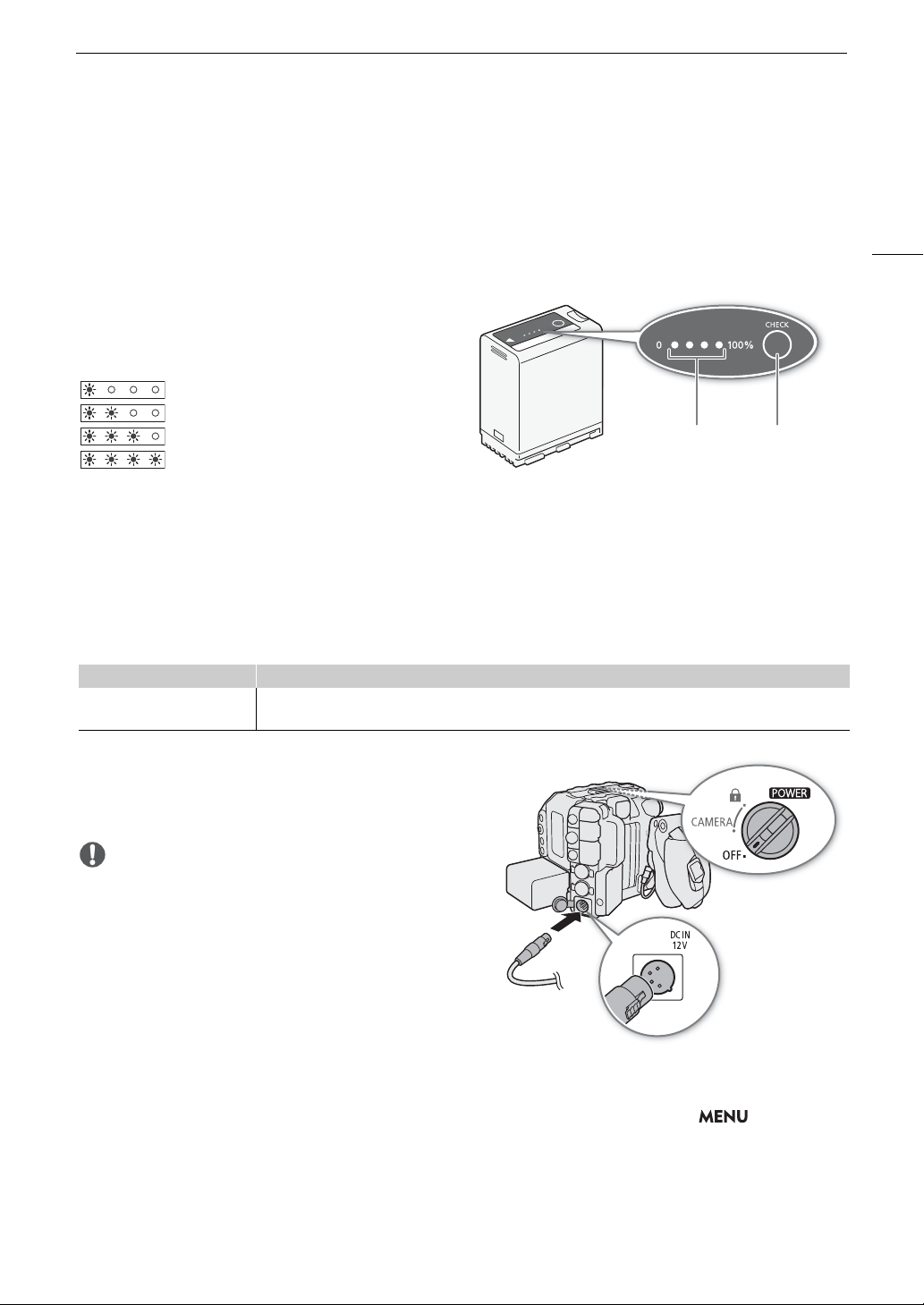
Checking the Remaining Battery Charge
When the camera is turned on, you can check the approximate remaining battery usage time (in minutes) by
B
looking at any recording/playback screen or the [
System Setup] status screen (A 203). You can also check
the approximate charge level on the battery pack itself. The remaining battery charge level displayed on the
recording/playback screen may not match the level shown on the status screen or the indicators on the battery
pack.
Press the CHECK button on the battery pack. An
indicator will light for approximately 3 seconds and show
the approximate remaining battery charge.
0-25%
26-50%
51-75%
76-100%
Using the DC IN 12V Terminal
When selecting commercially available AC adapters, make sure the external power source meets the following
specifications and all the safety standards of the country/region where it is used. Closely follow the
manufacturer’s instructions regarding the use and maintenance of AC adapters.
For information about the camera’s power consumption, refer to
Specifications
(A 228).
27
Power source Specifications
AC adapter
(DC IN 12V terminal)
4-pin XLR plug (female connector), 11.5 V to 20 V DC, 10 A (acceptable maximum load current)
1 Turn off the camera.
2 Connect the AC adapter’s 4-pin XLR connector to
the camera’s DC IN 12V terminal.
• Make sure to turn off the camera before connecting or
disconnecting an external power source to/from the
camera’s DC IN 12V terminal.
Checking the Power Supply Levels
B
You can check the voltage level of an AC adapter on the screen (A 55). You can use the > [
System
Setup] > [DC IN Warning (V)] setting to set a critical power level for the AC adapter. When the power input to the
camera reaches the predetermined level, the onscreen power indicator will change to red and an error message
will appear.
Page 28

Preparing the Power Supply
NOTES
• If the power supplied to the camera is at or below the level set for the power level warning (A 196), the
camera will not start recording. If the power supply’s voltage falls below the level necessary to operate the
28
camera while recording, recording will stop and the camera will turn off.
Page 29
Preparing the Handle Unit and LCD Monitor
NOTES
Preparing the Handle Unit and LCD Monitor
The LCD screen is necessary to complete the initial setup of the camera, so how to attach the supplied handle
and LCD monitor will be explained in this section. To learn more about using other optional and supplied
accessories, refer to
Guide (PDF file), available for download from your local Canon website.
Preparing Other Accessories
Attaching the Handle Unit
1 Slide the mounting base at the bottom of the handle unit into
the camera’s top accessory shoe and gently push it all the way
forward.
2 Tighten the locking knob to firmly secure the handle in place.
• The handle unit has 0.64 cm (1/4") sockets, giving you the option to
attach a variety of commercially available accessories.
• If you plan to attach to the handle unit multiple heavy accessories
(optional or commercially available), reinforce the handle using a
0.64 cm, 1/4" hex socket head bolt (supplied) through the rear
mounting hole.
• If necessary, use the supplied hex wrench for 0.64 cm, 1/4" screws to
tighten the locking knob and the rear reinforcement mounting bolt.
(A 40) and to the Cinema EOS System Expansion User
29
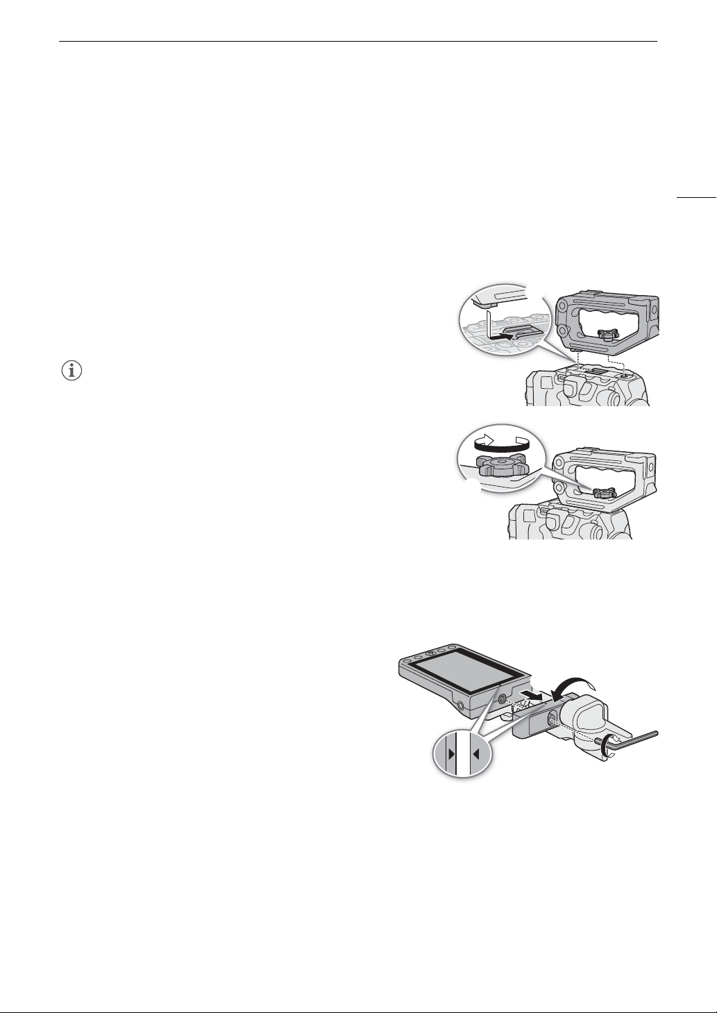
Attaching the LCD Monitor
Using the attachment unit, you can attach the LCD monitor to the handle unit or the camera itself.
Attaching the LCD Monitor to the Handle Unit
1 Turn off the camera.
2 On the LCD attachment unit, rotate the LCD monitor
mount in the direction of the locking knob to make the
LCD monitor fixation bolt accessible.
3 Attach the LCD monitor to the LCD monitor mount.
• Align the Í marks on the monitor and monitor mount. If
necessary, you can also mount the LCD monitor facing
the other way around.
• Tighten the LCD monitor fixation bolt using the supplied
hex wrench for 0.64 cm, 1/4" screws.
4 Attach the LCD attachment unit to the handle unit.
• Align the attachment mount on the LCD attachment unit to the handle unit’s front accessory mount.
• Tighten the locking knob firmly.
5 Rotate the LCD monitor 90 degrees toward the handle unit.
Page 30
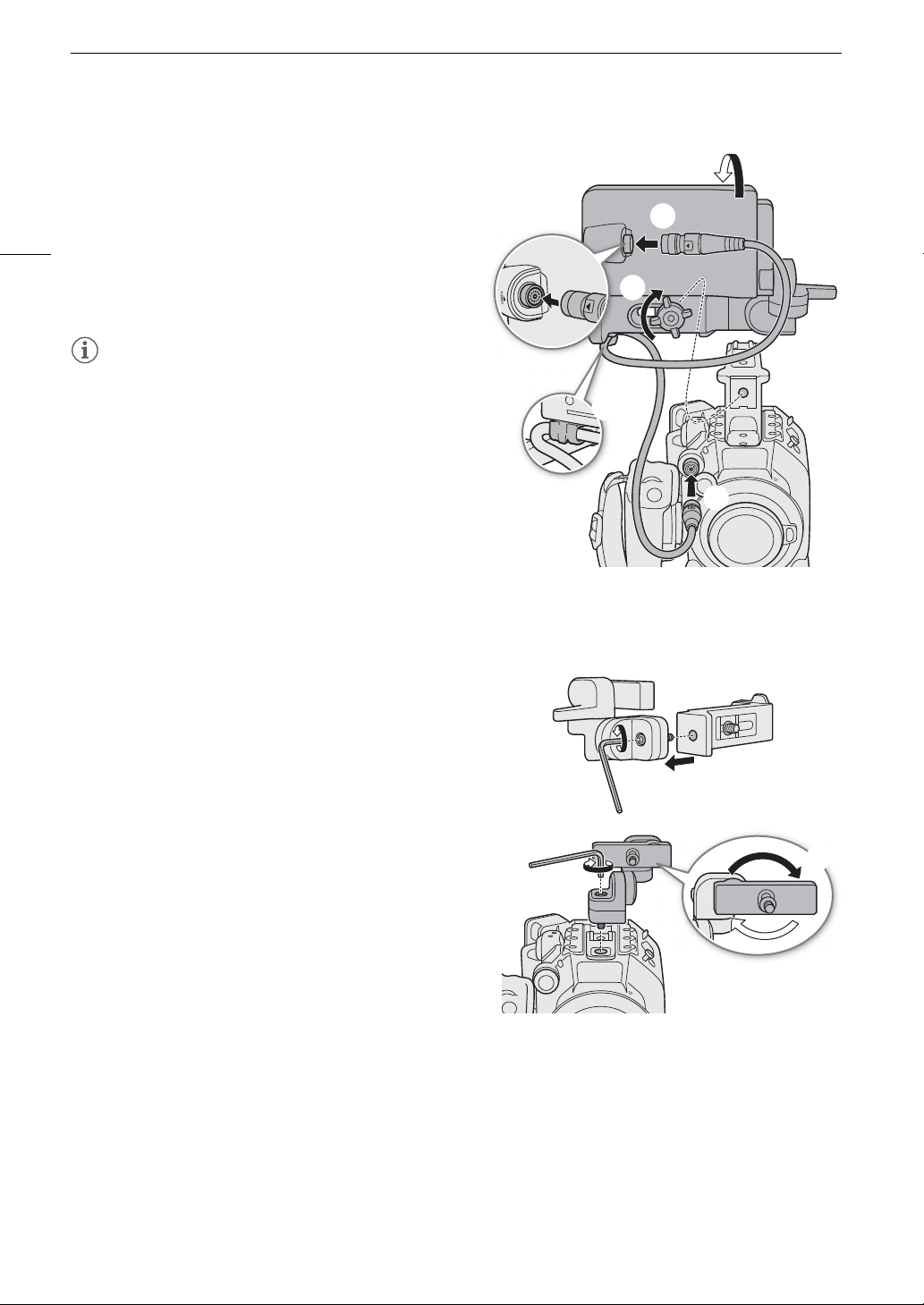
Preparing the Handle Unit and LCD Monitor
NOTES
6 Connect the LCD monitor to the camera’s VIDEO
terminal using the supplied UN-5 Unit Cable.
Í
•Align the
30
terminals.
7 Put the cable through the LCD attachment unit’s cable
clamp.
• If necessary, adjust the position of the cable so that it
does not get in the picture or obstruct the view.
• Depending on the situation, the screws may become
loose. If necessary, use the supplied hex wrench for
0.64 cm, 1/4" screws to tighten them.
marks on the cable’s plugs and
Attaching the LCD Monitor to the Camera
For this procedure, left and right directions are given as seen from the front of the camera (user facing the lens
mount).
1 Turn off the camera.
• If the handle unit is attached to the camera, remove it.
2 On the LCD attachment unit, remove the base 2 fixation
bolt to separate base 1 from base 2.
• Use the supplied hex wrench for 0.64 cm, 1/4" screws.
3 Attach the LCD attachment unit’s base 2 to the camera’s
top accessory mount so the pivots are on the right side.
• Use the same hex wrench and bolt to secure it firmly.
4 Rotate pivot B 90 degrees toward the back of the camera
(the side with the battery compartment) and rotate the
LCD monitor mount 180 degrees to the right.
5 Attach the LCD monitor to the LCD monitor mount.
Í
•Align the
• Tighten the LCD monitor fixation bolt using the
supplied hex wrench for 0.64 cm, 1/4" screws.
6 Rotate the LCD monitor 90 degrees right and then
90 degrees down so it is vertical and facing the back of
the camera.
marks on the monitor and monitor mount.
Page 31

7 Connect the LCD monitor to the camera’s VIDEO
NOTES
LCD monitor mounted on the cameraLCD monitor mounted on the handle unit
terminal using the supplied UN-5 Unit Cable.
Í
•Align the
terminals.
• If necessary, adjust the position of the cable so that it
does not get in the picture or obstruct the view.
• Depending on the situation, the screws may become
loose. If necessary, use the supplied hex wrench for
0.64 cm, 1/4" screws to tighten them.
marks on the cable’s plugs and
Preparing the Handle Unit and LCD Monitor
31
Adjusting the LCD Monitor
The LCD attachment unit’s various pivots allow you to rotate the position of the LCD monitor in a number of
ways to match your shooting style. The following are suggested positions, assuming the user is behind the
camera and can see the LCD monitor and the subject.
Page 32

Preparing the Handle Unit and LCD Monitor
NOTES
IMPORTANT
NOTES
• Based on the LCD monitor’s position, you can invert the image displayed on the screen. Repeatedly pressing
the MIRROR button will change the displayed image in the following order: Image inverted horizontally
32
Image inverted vertically Image inverted horizontally and vertically Original image.
• You can adjust the brightness, contrast, color saturation, sharpness and luminance of the LCD screen with the
¢
respective settings in the > [
• In CAMERA mode, you can use the > [
change the LCD monitor to black and white display. Even when the captured image is displayed in black and
white, onscreen displays and icons will be shown in color.
B
• You can use the > [
response to touch input.
System Setup] > [Touch Screen Response] setting to adjust the LCD monitor’s
Monitoring Setup] menu (A 189).
¢
Monitoring Setup] > [B&W Image: VIDEO Term.] setting to
Removing the LCD Monitor and LCD Attachment Unit
1 Turn off the camera.
2 Disconnect the unit cable from the camera’s and
monitor’s VIDEO terminals.
• Pull back the metallic tip of the plug and then
disconnect the cable from the terminal.
3 Loosen the locking knob and remove the LCD
attachment unit and monitor.
• Be careful not to drop the camera when attaching or
removing the LCD monitor.
• If the LCD attachment unit’s locking knob was fastened
very tight, you may need to use the supplied hex wrench
for 0.64 cm, 1/4" screws to loosen it.
Page 33

Date, Time and Language Settings
NOTES
Date, Time and Language Settings
Setting the Date and Time
You will need to set the date and time on the camera before you can start using it. The [Date/Time] screen will
appear automatically when the camera’s clock is not set.
1 Select the desired time zone and move to the next field.
• Joystick: Push the joystick up/down to make the selection and then press SET (press the joystick itself).
Dial: Turn the SELECT dial to make the selection and then press the SET button.
• You can also push the joystick left/right to move between the fields.
• The default time zone is [UTC-05:00] (New York) or [UTC+01:00] (Central Europe), depending on the
country/region of purchase. Time zones are based on Coordinated Universal Time (UTC).
2 Change the rest of the fields in the same way.
3 Select [Set] and then press SET.
33
• You can display the date/time with the > [¢Monitoring Setup] > [Custom Display 2] (CAMERA
mode) or [Custom Display] (MEDIA mode) > [Date/Time] setting.
• With the following settings, you can change the time zone, date and time also after the initial setup. You can
also change the date format and clock format (12 or 24 hours).
- > [BSystem Setup] > [Time Zone], [Date/Time] and [Date Format]
• When you do not use the camera for about 3 months, the built-in backup battery may be depleted completely
and the date and time setting may be lost. In such case, recharge the built-in backup battery (A 221) and set
the time zone, date and time again.
• Using the optional GP-E2 GPS Receiver, you can have the camera adjust settings automatically according to
the UTC date/time information received from the GPS signal (A 196).
Changing the Language
The camera’s default language is English. You can change it to German, Spanish, French, Italian, Polish,
Portuguese, Russian, Simplified Chinese, Korean or Japanese. Please note that some settings and screens will
be displayed in English, regardless of the language setting.
Refer to
procedure.
Selecting an Option from the Menu
1 Select > [BSystem Setup] > [LanguageH].
2 Select the desired language and press the MENU button to close the menu.
(A 34) for details on how to navigate the menu to complete this
Page 34

Using the Menus
SET button
Press the SET button (in the manual,
“press SET”) to confirm a selection.
SELECT dial
Turn the dial to move the orange
selection frame in the menu or to browse
quickly through a long list of options.
CANCEL button
Press to return to the previous menu/
submenu level or to stop some
operations that are in progress.
MENU button
Press the button to open the setup
menus and then press again to close the
menu after adjusting desired settings.
Joystick/SET button
When making a menu selection, push
the joystick to move the orange selection
frame in the menu. Then, press the
joystick itself (in the manual, “press SET”)
to select the menu item indicated by the
orange selection frame.
CANCEL button
MENU button
SELECT dial/SET button
Joystick
Joystick
CANCEL button
MENU button
Joystick
Using the Menus
Many of the camera’s functions can be adjusted from the menu that opens after pressing the MENU button. In
CAMERA mode, you can also register frequently used menu settings in a customized menu (My Menu) for easy
access. For details about the available menu options and settings, refer to
34
Menu Options
(A 185).
Selecting an Option from the Menu
The following is a step-by-step explanation of how to select a typical option from the setup menus. Some menu
items may require additional steps. Such operations will be explained in the respective section of the manual.
For brevity's sake, references to menu settings throughout the manual will be abbreviated as follows:
> [
B
System Setup] > [Language H] > Desired option
1 Press the MENU button.
• The menu opens with the orange selection frame indicating the menu item that was selected the previous
time the menu was closed (unless the camera was turned off).
2 Push the joystick left/right or turn the SELECT dial to select the icon of the desired setup menu.
• In the example, the Bicon, corresponding to the [System Setup] menu.
• If one of the icons in the top row is not selected when you open the menu, first push the joystick up or press
the CANCEL button to move the orange selection frame to one of the icons.
Page 35

Using the Menus
NOTES
3 Press SET (press the SET button or press the joystick itself).
• You can also push the joystick down to move the cursor to the list of menu items.
4 Select the desired menu item ([Language H], in the example) and then press SET.
• Joystick: Push the joystick up/down to select a menu item in the current page, or left/right to scroll through
the menu pages.
Dial: Turning the SELECT dial will scroll through all the menu items and all the menu pages consecutively.
5 Push the joystick up/down or turn the SELECT dial to select the desired setting option and then
press SET.
• The currently selected option is indicated with a mark.
• When many options are available, a scroll bar will appear on the right. Scroll up or down to see other
options.
• Press the CANCEL button instead to return to the menu page without changing the setting. In submenus,
you can also select [L] and press SET to return to the previous menu level.
6 Press the MENU button to close the menu.
• Unavailable items may appear grayed out.
• Pressing the MENU button at any time closes the menu.
• On some screens, the following icons may be displayed as a guide: , , . They refer, respectively,
to pressing the joystick or SET button, the MENU button and the CANCEL button.
• When an optional RC-V100 Remote Controller is connected to the camera, you can use the remote
controller’s up/down/left/right/SET buttons in the same way as the camera’s joystick. Pressing the SET button
is equivalent to pressing the joystick on the camera.
• You can check most of the current settings on the status screens (A 198).
35
Using the Customized Menus (My Menu)
In CAMERA mode, you can register up to 6 frequently used menu settings under a My Menu page for easy
access. You can save up to 5 separate sets of My Menu settings so you can customize different options for
different shooting situations. Furthermore, if you set an assignable button to [My Menu] (A 123), you can press
the button to access your registered menu settings even faster and more easily.
Selecting a My Menu Set
Select > [¥ My Menu] > Desired menu page.
• Each My Menu set corresponds to a separate menu page (! to %). Select the page of the My Menu set you
wish to use.
Adding Menu Settings
1 Select > [¥ My Menu] > [Edit] > [Register].
• A screen will appear where you can select the menu setting you want to add.
• Press the CANCEL button to cancel the operation and return to the regular menu.
2 Select the menu setting you want to add.
3 Select [OK] twice.
• The menu setting you registered will now appear under the currently selected My Menu set.
Page 36

Using the Menus
Current character / Character limit
Rearranging Menu Settings
1 Select > [¥ My Menu] > [Edit] > [Move].
2 Select the menu setting you want to move.
]
36
•The
icon will appear next to the setting you selected to move.
3 Move the menu setting to the desired position and press SET.
Removing Menu Settings
1 Select > [¥ My Menu] > [Edit] > [Delete].
2 Select the menu setting you want to remove.
3 Select [OK] twice.
Resetting All the My Menu Sets
Reset all the menu settings registered to the currently selected My Menu set.
1 Select > [¥ My Menu] > [Edit] > [Reset All].
2 Select [OK] twice.
Renaming My Menu Sets
You can give each of the 5 My Menu sets a more descriptive name to make them easier to identify.
1 Select > [¥ My Menu] > [Edit] > [Rename].
2 Enter the desired name (8 characters long) using the keyboard screen (see the following sidebar).
Using the keyboard screen
1 Select a character and press SET to add it to the text.
• Select the arrows (///) to move the cursor and the
backspace character ( ) to delete the last character entered.
• Repeat this step as necessary to enter the desired text.
• Depending on the menu setting, not all characters may be
available.
2 After entering the desired text, select [OK] to confirm the text and
close the keyboard screen.
• Press the CANCEL button instead to close the screen without making any changes.
Page 37

Preparing the Lens
IMPORTANT
NOTES
NOTES
Preparing the Lens
As much as possible, attach and remove the lens quickly and in a clean environment free of dust. Refer also to
the instruction manual of the lens used.
• When attaching/removing a lens, avoid direct sunlight or strong light sources. Also, be careful not to drop the
camera or lens.
• After removing a lens/When a lens is not attached to the camera:
- Do not touch the lens’s surfaces, the lens mount or any components inside the lens mount area.
- Place the body cap back on the lens mount and the dust caps on the lens. Clean any dust or dirt from the
body cap and dust caps before using them.
Attaching an EF Lens
1 Turn off the camera.
2 Remove the body cap from the camera and the dust
caps from the lens.
3 Attach the lens to the camera and turn the lens in the
direction of the arrow until it clicks in place.
• EF lenses: Align the red mark on the lens with the red EF
lens mount index mark on the camera.
• EF-S lenses: Align the white mark on the lens with the
white EF-S lens mount index mark on the camera.
37
Removing an EF Lens
1 Turn off the camera.
2 Hold down the lens release button and turn the lens all the
way in the direction of the arrow until it stops.
3 Remove the lens.
4 Place the body cap back on the lens mount and the dust
caps on the lens.
• Turning on the image stabilization function of an EF lens may reduce the effective usage time of the battery
pack. When image stabilization is not necessary, for example if the camera is fixed to a tripod, it is
recommended to turn it off.
• Depending on the lens used, you may experience one or more of the following limitations.
- The lens model name may be shortened when displayed on the screen.
Page 38

Preparing the Lens
IMPORTANT
NOTES
- You may not be able to focus manually when the focus mode switch is set to AF.
- You may not be able to use the focus preset function on super telephoto lenses.
- You may not be able to use the power zoom function on lenses with that function.
• This camera’s sensor is larger than the sensor size for which EF-S lenses are designed (APS-C). When using
38
EF-S lenses with this camera, you may notice peripheral illumination fall-off or vignetting.
• When using a compatible lens, you can use the > [BSystem Setup] > [Retract Lens] setting to retract
the lens automatically when the camera’s power is turned off with the focus mode set to AF.
• You can attach a B4 (broadcast) lens to the camera using the optional MO-4E or MO-4P B4 Mount Adapter. For details
refer to the Cinema EOS System Expansion User Guide.
- When using a B4 mount adapter, make sure to set > [Æ Recording/Media Setup] > [Sensor Mode]
to [Super 16mm (Cropped)] and > [v Camera Setup] > [Mount Adapter] to [MO-4E] or [MO-4P].
- Furthermore, when an optional EU-V2 Expansion Unit 2 with a commercially available V-mount battery is
attached to the camera, if you connect the lens’s 12-pin camera interface cable to the EU-V2’s LENS
terminal, you will be able to zoom and use the push auto iris function from the camera.
- When using a B4 lens compatible with the L.C.A.C. (automatic lens chromatic aberration correction)
function, if the 12-pin interface cable is connected, the lens’s chromatic aberration can be corrected. In such
case, will appear on the left of the screen, next to the mount adapter’s icon.
Updating the Firmware of an EF Lens
You can update the lens firmware of the EF lens attached to the camera. For details about firmware updates for
EF lenses, visit your local Canon website.
1 Download the lens firmware update file from the Canon website and save it on an SD card. Insert the
SD card containing the lens firmware update into the camera (A 45).
2 Attach the lens you want to update and turn on the camera in CAMERA mode.
3Select > [
• The current lens firmware version will appear on the screen.
• If the [Lens] option is grayed out, the attached lens may not support firmware updates or the SD card used
may not contain a valid lens firmware file. Check the lens and SD card and repeat the procedure from the
beginning.
B
System Setup] > [Firmware] > [Lens].
4Select [OK].
5 Select the lens firmware file (.LFU file).
6Select [OK].
• The lens firmware will be updated. Once in progress, the lens firmware update cannot be canceled.
7 When the confirmation message appears, press SET.
• Be sure to observe the following precautions while the lens firmware is being updated.
- Do not turn off the camera and do not remove the battery pack or other power source.
- Do not remove the lens.
- Do not operate any buttons or controls on the camera.
- Do not open the card compartment cover and do not remove the SD card.
• The lens firmware cannot be updated while pre-recording is activated.
• Power the camera using an AC adapter or a sufficiently charged battery pack.
• When using an optional EF extender, remove the extender before performing the procedure.
Page 39

Preparing the Lens
NOTES
In-Camera Lens Correction
Depending on the characteristics of the lens used, the corners of an image frame may be darker than the center
due to light fall-off (peripheral illumination drop), color shift/color fringing may be visible along high-contrast
edges in the image (chromatic aberration), or the image produced may not be as sharp at certain apertures (lens
diffraction). In CAMERA mode, you can apply a correction to compensate as necessary. To apply peripheral
illumination or chromatic aberration correction, correction data for the lens used is necessary. Automatic
chromatic aberration correction is available for broadcast lenses compatible with L.C.A.C.
Chromatic aberration and diffraction correction are not applied to RAW recordings but will be applied to proxy
clips recorded simultaneously with RAW clips.
1 Attach the lens you want to use and turn on the camera in CAMERA mode.
v
2 Select > [
Correction].
• If correction data is not available, [Periph. Illum. Corr.] or [Chromatic Aberr. Corr.] will appear grayed out. Visit
your local Canon website and check if there is correction data available for the lens you are using. If so,
download the necessary update package, update the camera’s firmware version and repeat the procedure
from the beginning.
3 Select [On].
• The camera will apply the correction for the attached lens to all future recordings.
Camera Setup] > [Periph. Illum. Corr.], [Chromatic Aberr. Corr.] or [Diffraction
39
• About in-camera lens correction data: The camera contains a register of correction data for compatible lenses
that were available at the time the camera went on sale. Correction data for future lenses will be made
available as part of the regular updates released for the camera’s firmware. For more details, visit your local
Canon website.
• Peripheral illumination/chromatic aberration correction cannot be applied in the following cases:
- When the appropriate correction data is not available for the lens attached.
- When using non-Canon lenses. Even if the corresponding menu setting is available (not grayed out), setting
it to [Off] is recommended.
• Diffraction correction cannot be applied when the camera cannot obtain the current aperture value of the lens.
• When peripheral illumination/diffraction correction is activated:
- Depending on the recording conditions, noise may appear in parts of the image.
- The level of correction will be lower for lenses that cannot provide distance information.
- The level of correction will be lower the higher the ISO speed/gain setting used.
- When using EF-S lenses, peripheral illumination fall-off may be more pronounced.
Page 40

Preparing Other Accessories
IMPORTANT
Configuration with
LCD monitor and grip
Configuration with LCD monitor,
grip and handle
Light configuration with grip
for hand-held shooting
Minimal configuration
with thumb rest
GR-V1 Camera
Grip Unit
Thumb rest
Handle unit LA-V2 LCD Attachment Unit
LM-V2 LCD Monitor
Microphone holder
Preparing Other Accessories
Your camera is incredibly versatile and allows you to build the shooting configuration that best fits your needs
and shooting conditions. In addition to the supplied accessories, Canon offers a variety of optional accessories
that expand the functionality of the camera (A 223). For details about accessories compatible with this camera,
40
please download the Cinema EOS System Expansion User Guide (PDF file), available from your local Canon
website.
How to attach and adjust the LCD monitor and handle was already explained in a previous section (A 29). This
section will cover other supplied accessories such as the camera grip and microphone holder.
Examples of Camera Configurations
• Be careful not to drop the camera or accessories when attaching, removing or adjusting the various
accessories. Use a table or other stable surface to change the camera’s configuration.
Page 41

Preparing Other Accessories
60° back 0° 90° forward
Removing and Attaching the Camera Grip
The camera grip comes originally attached to the camera. You can remove it and replace it with the thumb rest
when a minimal configuration is necessary.
Removing the Camera Grip
1 Turn off the camera.
2 Unscrew the camera grip’s locking screw and gently
detach the grip.
• The camera grip contains an internal connection cable
so be sure not to pull it too forcefully.
3 Remove the grip attachment ring and disconnect the
camera grip’s connection plug.
• You can attach the grip attachment ring to the
connection cable so that you do not lose it.
41
4 Screw the thumb rest onto the camera.
Attaching the Camera Grip
The camera grip can be attached in a number of positions
from 90° toward the lens to 60° toward the back at 6°
intervals.
1 Turn off the camera.
2 Unscrew the thumb rest and remove it from the camera.
3 Lay the camera on a flat, stable surface with the rosette
facing up.
4 Firmly insert the camera grip’s connection plug all the
way into the GRIP terminal on the camera.
• Make sure to insert the plug all the way in, until the
terminal is not visible.
• If the plug is not correctly connected, all the controls
on the camera may be disabled (A 208).
5 Attach the grip attachment ring.
6 Return the camera to an upright position.
7 Attach the camera grip to the camera aligning it at the
desired angle and tighten the camera grip’s locking
screw.
Page 42

Preparing Other Accessories
Attaching the Microphone Holder
1 Attach the microphone holder to the LCD attachment unit.
2 Use a commercially available Phillips head (“crosshead”)
42
screwdriver to secure it firmly with the supplied M4 bolts.
Page 43

Preparing Recording Media
IMPORTANT
NOTES
Preparing Recording Media
The camera records clips1 on CFexpress or SD cards2 and photos on SD cards. The camera has two
CFexpress card slots and you can use two cards (in the manual, “CFexpress A” and “CFexpress B”) to record on
both simultaneously or to automatically switch to the other card when the card in use is full (A 47).
Initialize cards (A 46) when you use them with this camera for the first time.
1
“Primary clips” (generally speaking, deliverable files) are recorded on a CFexpress card. “Proxy clips” (smaller files, mainly
intended for offline editing) are recorded on the SD card.
2
The SD card is used also to save/read other files in addition to proxy files.
Compatible Recording Media
The following types of memory card can be used with this camera. For the latest information about recording
media tested for use with this camera, visit your local Canon website.
CFexpress cards
CFexpress cards compliant with CFexpress 2.0 Type B specifications.
However, it may not be possible to record on the card depending on the camera mode and bit rate used. For
details about CFexpress cards tested for use with this camera, visit your local Canon website.
43
SD cards
SD card type:
SD Speed Class
UHS Speed Class
1
As of April 2020, the clip recording function has been tested using SD cards made by Panasonic, Toshiba and SanDisk.
2
UHS and SD Speed Class are standards that indicate the minimum guaranteed data transfer rate of SD cards.
3
Using an SD card rated UHS Speed Class U3 is recommended to record using slow motion recording.
1
./ 0
SD cards SDHC cards SDXC cards
2
:
2, 3
:
Speed Class U1 Speed Class U3
• CFexpress cards can become hot due to the high operating temperature inside the camera. Removing a
CFexpress card immediately after using it for recording may cause burns or cause you to drop the card,
resulting in damage to the card.
• After repeatedly recording, deleting and editing clips (if the memory is fragmented), you may notice slower
writing speeds to the card and recording may even stop. In such case, save your recordings and initialize the
card with the camera. Be sure to initialize cards especially before shooting important scenes.
• About CFexpress and SDXC cards: You can use CFexpress and SDXC cards with this camera but these types of
cards are initialized by the camera using the exFAT file system.
- When using exFAT-formatted cards with other devices (digital recorders, card readers, etc.), make sure that
the external device is compatible with exFAT. For more information on compatibility, contact the computer,
operating system or card manufacturer.
- If you use exFAT-formatted cards with a computer OS that is not exFAT-compatible, you may be prompted
to format the card. In such case, cancel the operation to prevent data loss.
• Proper operation cannot be guaranteed for all cards.
Page 44

Preparing Recording Media
CFexpress card
access indicators
Inserting a CFexpress Card
1 Slide the card compartment cover switch all the way in
the direction of the arrow.
44
• The card compartment cover will open to the left.
2 Insert the card straight, with the label facing the back of
the camera (the side with the battery compartment) all the
way into one of the CFexpress card slots.
• You can use two cards, one in each card slot.
3 Close the card compartment cover.
• Do not force the cover closed if the card is not correctly
inserted.
CFexpress card access indicators
CFexpress /
CFexpress indicator
Red Accessing the card.
Green Recording/playback is possible and the CFexpress card is selected for recording/playback.
Off A card is not inserted or the card slot is not currently selected.
B
If you set > [
will not illuminate.
System Setup] > [CFexpress Access LED] to [Off], the CFexpress card access indicators
Card status
Removing a CFexpress Card
1 Wait until the CFexpress card access indicator is off or is
illuminated in green.
2 Slide the card compartment cover switch in the direction of
the arrow.
• The card compartment cover will open to the left.
3 Make sure the CFexpress card access indicator is off and
then push the CFexpress card release button.
4 Pull out the CFexpress card and close the card
compartment cover.
Page 45

Inserting and Removing an SD Card
IMPORTANT
SD CARD
indicator
1 Wait until the SD CARD access indicator is off or is
illuminated in green.
2 Slide the card compartment cover switch all the way in
the direction of the arrow.
• The card compartment cover will open to the left.
3 Insert the card straight, with the label facing the back
of the camera (the side with the battery compartment)
all the way into the SD card slot until it clicks.
• To remove the card, make sure the SD CARD indicator is
off and then push the card once to release it. When the
card springs out, pull it all the way out.
4 Close the card compartment cover.
• Do not force the cover closed if the card is not correctly
inserted.
SD card access indicator
SD CARD indicator SD card status
Red Accessing the card.
Green
Off
CAMERA mode: Proxy clip recording is activated and the card is ready for recording.
MEDIA mode: Playback from the card is possible.
• A card is not inserted in the camera or the card is write-protected.
• CAMERA mode only: A card is inserted but proxy clip recording is not activated.
Preparing Recording Media
45
If you set > [
B
System Setup] > [SD Card Access LED] to [Off], the SD card access indicator will not
illuminate.
• SD cards have front and back sides that are not interchangeable. Inserting a card facing the wrong direction
can cause a malfunction of the camera. Be sure to insert the card as shown in the illustration.
Page 46

Preparing Recording Media
IMPORTANT
NOTES
Initializing Recording Media
Initialize cards when you use them with this camera for the first time. You can also initialize a card to permanently
delete all the recordings it contains.
46
1Select > [Æ Recording/Media Setup] > [Initialize Media].
2 Select [CFexpress A], [CFexpress B] or [SD Card].
3Select [OK].
• The card is initialized and all the data it contains is erased.
4 When the confirmation message appears, press SET.
• SD cards are initialized using the FAT12 / FAT16 file system, SDHC cards using the FAT32 file system, and
SDXC and CFexpress cards using the exFAT file system.
• Initializing a card will permanently erase all data, including photos and protected custom picture files. Lost data
cannot be recovered. Make sure you save important recordings in advance.
• Depending on the card, initialization may take up to a few minutes.
• When relay recording is activated, while you keep recording on one CFexpress card, you can initialize another
CFexpress card in the other card slot.
• If you set an assignable button to [Initialize Media] (A 123), you can press the button to open the [Initialize
Media] submenu.
Switching Between CFexpress Card Slots
The camera features two CFexpress card slots, CFexpress and CFexpress . If both slots contain a card,
you can switch between them as necessary.
Press the SLOT SELECT button.
• The access indicator of the selected CFexpress card slot will
illuminate in green. On the screen, the CFexpress card selected is
indicated with a mark next to the card icon.
• You cannot use the SLOT SELECT button to switch between
CFexpress card slots while recording or playing back.
• You can also perform this function remotely using Browser Remote
177,
on a connected network device (A
181).
Page 47

Preparing Recording Media
NOTES
Relay Recording and Double Slot Recording
In CAMERA mode, the camera features two convenient recording methods that can be used when both
CFexpress card slots contain a card: relay recording and double slot recording.
Relay Recording
This function allows you to continue recording on the other card without interruption when the card you are using
becomes full. Relay recording is available from CFexpres card slot A to CFexpress card slot B, and vice versa.
However, relay recording is disabled (the camera will not switch to the other card) when slow & fast motion
recording is activated.
Select > [Æ Recording/Media Setup] > [Relay Recording] > [On].
• Both CFexpress card icons will turn green.
Double Slot Recording
This function records the same clip simultaneously to both cards, which is a convenient way to make a backup
copy of your recordings while you record.
This function cannot be used together with relay recording or slow & fast motion recording.
Select > [Æ Recording/Media Setup] > [Double Slot Recording] > [On].
• 4 appears at the top of the screen and both CFexpress card icons turn green.
47
• If a card becomes full during double slot recording, recording on both cards will stop. On the other hand, if an
error occurs with one of the cards, recording will continue on the other card.
• When using network functions, relay recording and double slot recording will be disabled while a connection
setting (SET file) is selected and the camera is connected to a network.
Checking the Remaining Recording Time on a Card
In CAMERA mode, the display on the upper left of the screen shows the card icons and the remaining recording
time* (in minutes) on each card (A 54).
On the [Æ Recording/Media Setup] status screen (A 204), you can check the total space, used space and
approximate remaining recording time* of each card. For the SD card only, the approximate remaining number of
photos and speed class will be displayed as well.
* Remaining recording times are approximate and calculated based on the current video configuration used.
Page 48

Preparing Recording Media
NOTES
Recovering Clips
Some actions, such as suddenly turning off the camera or removing the card while data is being recorded, can
cause data errors in the recorded clip. In MEDIA mode, you may be able to recover clips with corrupted data
using the following procedure.
48
1 Set the camera to MEDIA mode and open the index screen with the clip you wish to recover
(A 135).
2 Select the desired clip (a clip with the icon instead of a thumbnail image).
3 Press SET to open the clip menu and select [Recover Clip] > [OK].
• The camera will attempt to recover the corrupted data.
4 When the confirmation message appears, press SET.
• In the [RAW] index screen, recovered clips appear with a Ð icon instead of the usual thumbnail.
• This procedure may delete clips shorter than 0.5 seconds in length.
• In some cases, it may not be possible to recover the data. This is more likely when the file system is corrupted
or the card is physically damaged.
• Only clips recorded with this camera can be recovered. Photos cannot be recovered.
Page 49

Adjusting the Black Balance
NOTES
Adjusting the Black Balance
In CAMERA mode, you can have the camera adjust the black balance automatically when ambient temperature
changes considerably or if there is a noticeable change in a true black video signal.
1 Attach the body cap to the lens mount and set the camera to CAMERA mode.
• If a lens was attached, turn off the camera and remove the lens. Place the body cap back on the lens mount
and turn on the camera.
2 Select > [v Camera Setup] > [ABB] > [OK].
• The automatic black balance procedure will start. It may take about 1 minute depending on the frame rate.
3 When the confirmation message appears, press SET.
• If the sensor is not completely shielded from light, [Error] will appear on the screen. Repeat the procedure
from the beginning.
• Adjusting the black balance is necessary in the following cases:
- When using the camera for the very first time or after a long period of not using it.
- After sudden or extreme changes in ambient temperature.
- After changing the sensor mode.
- After activating or deactivating slow & fast motion recording (including switching to another special recording
mode).
- After changing the shooting frame rate, when slow & fast motion recording is activated.
- After resetting the camera’s settings.
• During the adjustment of the black balance, you may notice some irregular displays appear on the screen. This
is not a malfunction.
49
Page 50

Adjusting the Black Balance
50
Page 51

3
CFexpress card
access indicators
Power indicator/
rear tally lamp
SD card access
indicator
Front tally lamp
Recording Video and Photos
Recording
51
This section explains the basics of recording clips* and photos. For details on recording audio, refer to
Audio
(A 101).
* “Clip” refers to a single movie unit recorded with a single recording operation. You can also include metadata with the clip.
Recording
1 Set the
• The camera turns on in CAMERA mode and enters record standby mode ([STBY]).
• The power indicator (rear tally lamp) will illuminate in green.
• The access indicators of card slots with a card inserted will illuminate momentarily in red. Then, the access
2 Press the REC button to begin recording.
• Recording starts. The tally lamps illuminate in red (the rear tally lamp changes from green (power indicator) to
• The access indicator of cards used for recording will illuminate in red.
• You can use the REC button on the camera or the one on the camera grip.
• You can also perform this function remotely using Browser Remote on a connected network device (A177,
• For details about recording proxy clips, refer to
3 Press the REC button to stop recording.
• The clip is recorded and the camera enters record standby mode. The front tally lamp goes out and the rear
• The access indicator of cards selected for recording will change back to green.
Q
indicators of cards selected for recording will change to green.
red) and the recording indicator at the top of the screen changes from [STBY] to [ÜREC].
181).
tally lamp changes from red to green (power indicator).
switch to CAMERA.
Proxy Clips (Simultaneous Recording)
(A 67).
Recording
Page 52

Recording Video and Photos
IMPORTANT
NOTES
NOTES
To take photos
In CAMERA mode, you can take photos using an assignable button. Photos are saved onto the SD card and
their size depends on the video configuration currently in use. For details, refer to
1 Set an assignable button to [Photo] (A 123).
52
2 When the camera is in record standby mode, press the assignable button.
•
8
appears at the top right of the screen and the photo is recorded on the SD card.
• The SD CARD access indicator will illuminate in red.
• Be sure to save your recordings regularly, especially after making important recordings. Canon shall not be
liable for any loss or corruption of data.
• You can use the review function (A 115) to play back part or all of the last clip recorded without having to
switch to MEDIA mode.
• If you record using metadata settings, those settings will be recorded with the clip. For more details, refer to
Using Metadata
• If the camera switches to the other CFexpress card while recording video due to the relay recording function
(A 47), the two parts (before/after the switch) will be recorded as separate clips.
• A single XF-AVC clip can be recorded continuously for up to 6 hours. At that point, a new clip will be created
automatically and recording will continue on a separate clip.
• To record photos, make sure the SD card is not write-protected.
• Photos cannot be recorded in the following cases.
- While recording video.
- When slow & fast motion recording is activated.
- When pre-recording is activated.
- While color bars are displayed.
- While Browser Remote is activated.
(A 113).
Specifications
(A 227).
Page 53

Recording Video and Photos
Continuous AF frame – always in white (A 86)
AF-Boosted MF frame – in yellow: manual adjustment range; in white: automatic adjustment range (A 85)
One-shot AF frame (A 85)
Face AF: Main subject (A 88)
Face AF:
Only one face detected or faces
other than the main subject
Tracking: Subject selection (A 89)
Tracking: During tracking Focus frame with focus guide (A 83)
Onscreen Displays
Refer to this section for an explanation of the various screen displays that appear in CAMERA mode. You can
use the custom display function (A 191) to turn off individual onscreen displays if they are not required. The
menu item that controls each display is given in the following tables (1: indicates a menu item under [Custom
Display 1] and 2: indicates a menu item under [Custom Display 2]).
The position of some icons and onscreen displays may change depending on the display level settings. The
following screenshot and tables describe the onscreen displays at display level 1 with the [All Displays] setting
(A 57).
53
AF frames
Depending on the focus function used you may see some of the following AF frames. You can also hide them
with the > [
¢
Monitoring Setup] > [Custom Display 1] > [Focus Mode] setting.
Page 54

Recording Video and Photos
Left side of the screen
Icon/Display Description Custom Display
0000 mm Approximate focal length of the lens. 1: [Focal Length]
A, @
54
, Face AF (A 88).
i
(in red) Lens error warning (A 210). 1: [Lens]
, B4 mount adapter.
/
00 Custom picture file selected (A127). 1: [Custom Picture]
, , , ,
,
, ,
, Light metering mode (A 77). 1: [Light Metering]
`
b
Q User memo (A 113). 2: [User Memo]
Focus mode (A 81). 1: [Focus Mode]
Image stabilization (A 90). 1: [Digital Image
Image stabilization disabled (the function is activated on the camera but turned off
on the lens).
• Available only when the optional MO-4E or MO-4P B4 Mount Adapter is
attached to the camera.
Automatic chromatic aberration correction for a broadcast lens.
• Available only when the optional MO-4E or MO-4P B4 Mount Adapter is
attached to the camera.
[Gamma/Color Space] setting in the custom picture file (A 130).
A viewing LUT has been applied to at least one display or output terminal
(A 151).
GPS signal: continuously on - satellite signal acquired; flashing - satellite signal not
acquired.
• Displayed only when an optional GP-E2 GPS Receiver is connected to the
camera.
Fan operation: in white – normal (A 61); in red – fan warning (A 210). 2: [Temperature/Fan]
Temperature warning (A 61).
• When the camera internal temperature rises above a certain level, b will
appear in yellow. If the temperature rises further, b will appear in red.
Stabilization]
1: [Mount Adapter]
1: [LUT]
2: [GPS]
Top of the screen
Icon/Display Description Custom Display
Recording media status, estimated remaining recording time and video format 2: [Remaining Rec Time]
, , 8
000 min
, , 8 (in red) END Card is full.
, , 9 (in red) No card or cannot record on the card.
r, Video format (A62).
, ,
, ,
/ : CFexpress card (primary clips); 8: SD card (proxy clips).
The card’s status is indicated by the icon’s color: in green – can record; in yellow –
card almost full (5 minutes or less); in red – card almost full (less than 1 minute); in
white – reading the card.
• The CFexpress card selected for recording is indicated with a mark.
Network connection status (A 173). 2: [Network Functions]
Page 55

Recording Video and Photos
Icon/Display Description Custom Display
4
Recording operation
STBY, ÜREC Clip recording: record standby, recording.
S&F STBY,
Ü
REC
S&F
PRE STBY,
Ü
REC
PRE
`
00.00P, 00.00i Frame rate (A 63).
U
00:00:00.00 / 00:00:00:00
R, P, F, E
Power supply level indicator 2: [Remaining Battery]
è
é
ê
ë
(in red)
000 min
DC IN 00.0V Power supply voltage when using an AC adapter.
è
é
ê
ë 000%,
00.0V
Double slot recording (A 47). 2: [Recording Mode]
Slow & fast motion recording (A 116): record standby, recording.
Pre-recording (A 119): record standby, recording.
Recording command (A 147, 148). 2: [Rec Command]
2: [Frame Rate]
When slow & fast motion recording is activated, the shooting frame rate is also
displayed (000/00.00P).
Genlock (A 99).
• Displayed only when an optional EU-V1 Expansion Unit 1 or EU-V2 Expansion
Unit 2 is attached to the camera.
Time code (A 95).
Time code status (A 96).
Remaining battery charge of a BP-A60 (supplied) or BP-A30 (optional) Battery Pack
and estimated remaining usage time (in minutes).
• When is displayed, replace the battery pack with a fully charged one.
• Depending on the conditions of use, the actual battery charge level may not be
indicated accurately or may not match the levels shown on the [B System
Setup] status screen or the indicators on the battery pack.
• When the voltage falls below the selected low-power warning level (A 196),
the voltage will be displayed in red.
Remaining battery charge of a commercially available V-mount battery.
• Available only when the optional EU-V2 Expansion Unit 2 is attached to the
camera.
• Depending on the battery used, the battery charge level cannot be indicated as
a percentage. In that case, the voltage will be displayed instead.
• When the power level falls below the selected low-power warning level
(A 196), the percentage or voltage will be displayed in red.
2: [Genlock]
2: [Time Code]
55
Right side of the screen
Icon/Display Description Custom Display
( only),
,
0000x0000 Resolution (A 62). 2: [Resolution/
00 bit,
YCC422 00 bit
7 Photo recorded on the SD card (A 52). 2: [Photo]
(in red) No SD card or cannot record photos on the SD card.
T
(in red) Output onscreen displays (A 149). 2: [OSD Output]
^ (in yellow) Magnification (A 84). 1: [Magnification]
J, K (in yellow) Peaking (A 84). 1: [Peaking]
Sensor mode (A 62). 2: [Sensor Mode]
Color depth, color sampling (A 62).
MON. terminal disabled / HDMI OUT terminal active (A 147). 2: [Output Terminals
Color Sampling]
Status]
Page 56

Recording Video and Photos
Icon/Display Description Custom Display
Audio limiter (A 107). 2: [Audio Level Indicator]
Audio level meter (A 106).
56
×
00, Headphone volume (A 139). –
Date/time 2: [Date/Time]
Bottom and center of the screen
Icon/Display Description Custom Display
A001C001 to Z999D999 Clip identification. Includes the camera index, reel number and clip number
components of the clip file name (A 59).
00 00 00 00 User bit (A 97). 2: [User Bit]
Exposure bar (A 77). 1: [Exposure Bar]
AE ±0.00 AE shift (A 77). 1: [AE Shift]
C
ÅA/ÅB, ¼, É, È,
00000K ±0CC
ND 00 stops ND filter (A 73). 1: [ND Filter]
E
, F00.0 / T00.0, closed Aperture value (A 74). 1: [Iris]
ISO 000000, 00.0dB ISO speed/Gain value (A 71). 1: [ISO/Gain]
000.00°, 1/0000.00, 000.00Hz Shutter speed (A 69). 1: [Shutter]
CH0/CH0,
CH0+CH0/CH0+CH0
Key lock (A 12). 1: [Key Lock]
White balance (A 78). 1: [White Balance]
Audio output channels (A 155). 2: [Monitor Channels]
2: [Reel/Clip Number]
Page 57

Recording Video and Photos
Example of the
[Main Recording Displays] option
Selecting the Onscreen Display Level
You can press the DISP button to change the onscreen display level and control the amount of information
shown over the image. In CAMERA mode, you can customize each display level individually.
Press the DISP button to select the desired display level.
• Repeatedly pressing the DISP button will change the display level:
Display level 1 Display level 2 Display level 3.
Customizing Onscreen Display Levels
In CAMERA mode, you can change the information displayed at each display level. In most cases, icons are
displayed at a smaller size. Only the [All Displays] option of display level 1 uses a larger size for onscreen
displays.
Select > [¢ Monitoring Setup] > [DISP Level 1], [DISP Level 2] or [DISP Level 3] > Desired option.
57
Options for display level 1
[All Displays]: All onscreen displays at a larger size.
[All Displays (Periph. Border)]:
All onscreen displays at a smaller size, more appropriate for use with the peripheral border
(A 58).
Options for display level 2
[Main Recording Displays]:
Only the onscreen displays most relevant for shooting.
[Only FUNC/MENU]:
Usually no onscreen displays except for the recording
operation (REC/STBY). When the FUNC or MENU button
is pressed, the necessary information will be displayed
temporarily (for as long as you are changing the settings).
Options for display level 3
[Only REC/STBY]:
No onscreen displays except for the recording operation (REC/STBY).
[No Displays]: No onscreen displays at all.
Page 58

Recording Video and Photos
NOTES
NOTES
Full-screen display Peripheral border display
Peripheral Border Display
You can apply the peripheral border display to all display levels in CAMERA mode. With the peripheral border
display, the camera’s image is reduced slightly so the onscreen displays are shown mostly around it and not on
top of it, partially hiding it.
58
Select > [¢ Monitoring Setup] > [Apply Peripheral Border] > Desired option.
Options
[DISP Level 1/2/3]:
Peripheral border display is always used.
[DISP Level 1/2]:
Peripheral border display is used for display levels 1 and 2.
[DISP Level 1], [Disp Level 2], [Disp Level 3]:
Peripheral border display is used for the respective display level.
[Off]: Full-screen display is always used.
Display Levels in MEDIA Mode
In MEDIA mode, the information displayed at each display level cannot be customized and the onscreen displays
during playback (A 138) will change as follows.
Recordings Display level 1 Display level 2 Display level 3
Clips
Photos Photo information No onscreen displays —
Joystick guide and playback
information about the clip
Only playback information
about the clip
No onscreen displays
• Some onscreen displays, such as video scopes, onscreen markers and AF frames will be displayed
permanently even at display level 2. Turn them off with their respective function or select display level 3.
• When the zebra pattern or false color display is activated, it will appear on the screen regardless of the
selected display level.
Page 59

Recording Video and Photos
A001C001_yymmddXX_CANON_01P
1 2 3 4 675
1 Camera index: One character (A to Z) that
identifies the camera used.
2 Reel number: 3 characters (001 to 999) that
identify the card used. The number is assigned
automatically but you can set the initial number.
After you insert a new card (just purchased or
initialized), the number advances by one when the
first recording is made.
3 Clip number: 4 characters (C001 to D999). The
clip number advances automatically with each
clip recorded (switching to D001 after C999), but
you can set the initial clip number and select the
clip numbering method.
4 Recording date (set automatically by the camera).
5 Random component: 2 characters (numbers 0 to
9 and capital letters A to Z) that change randomly
with each clip.
6 User defined field: 5 characters (numbers 0 to 9
and capital letters A to Z) for any other
identification purposes.
7 Proxy clips only*: The camera will automatically
add the suffix “_P” to the file name of proxy clips.
Additionally, when an SD or SDHC card is used to
record proxy clips, a stream number (01 to 99) will
be added before the “P”. The stream number will
advance every time the video (stream) file within
the clip is split and recording continues on a
separate stream file.
Setting a Card’s Volume Label
In CAMERA mode, you can set the volume label for CFexpress cards and SDXC cards used for recording, in
order to make it easier to identify and organize them later.
1 Select > [Æ Recording/Media Setup] > [Volume Label] > [Canon] or [Canon + Metadata].
2 Initialize the card (A 46).
3 If necessary, set the clip file name’s metadata elements (A 59).
4 Record clips on the card.
• The card’s volume label changes when the first recording is made on a just initialized card. (For SDXC cards
only when the first proxy clip is recorded.)
Options
[Canon]: The volume label of CFexpress and SDXC cards will be “CANON” regardless of the clip file name
settings.
[Canon + Metadata]:
The volume label of CFexpress and SDXC cards will be “CANONX999” where “X” represents the
camera index and “999” represents the reel number set in the clip file name’s metadata settings.
59
Setting the Clip File Name
The camera allows you to change several settings that determine the clip file name of recorded clips. Personalize the
clip file name according to your preferences or organizational conventions to create files that are easier to identify
and organize. This function can only be used in CAMERA mode.
The basic file name structure is as follows.
* Apart from this component, the file name of the primary clip ( RAW or XF-AVC, RAW only) and the proxy clip
(XF-AVC) will be identical.
Page 60

Recording Video and Photos
Setting the Components of the Clip File Name
To set the camera index
1 Select > [Æ Recording/Media Setup] > [Metadata] > [Camera Index].
60
2 Select the desired camera index and then select [Set].
To set the clip numbering method
Select > [Æ Recording/Media Setup] > [Metadata] > [Clip Numbering] > [Reset] or
[Continuous].
Options
[Reset]: The clip number will restart from 001 every time you insert a new card.
[Continuous]: Clip numbers will start from the initial number set with [Clip Number] (following procedure) and
continue across multiple cards.
To set the reel number or initial clip number
The initial clip number can only be set when [Clip Numbering] is set to [Continuous].
1 Select > [Æ Recording/Media Setup] > [Metadata] > [Reel Number] or [Clip Number] > [Change].
• To reset the reel/clip number to [001], select [Reset] instead.
2 Enter the reel/clip number using the data entry screen (A 60).
To set the user-defined field
1 Select > [Æ Recording/Media Setup] > [Metadata] > [User Defined] > [Change].
• To reset the user-defined field to [CANON], select [Reset] instead.
2 Enter the desired text string using the data entry screen (A 60).
Using the data entry screen
1 Select the first character or digit and then press SET to move to the
next.
• You can also push the joystick left/right to move between the
fields.
• Change the rest of the characters/digits in the same way.
2 Select [Set] to confirm the text or value and close the data entry
screen.
• Press the CANCEL button instead to close the screen without
making any changes.
Page 61

Recording Video and Photos
IMPORTANT
NOTES
NOTES
Using the Fan
The camera uses a cooling fan to lower the camera’s internal temperature. In CAMERA mode, you can change
the fan’s operation mode and speed. In MEDIA mode, the fan runs at all times but you can select its speed.
Setting the Fan’s Operation in CAMERA Mode
1 Select > [B System Setup] > [Fan Mode] > Desired option.
If you selected [Always On]
2 Select > [
If you selected [Automatic]
2 Select > [
3 Select > [B System Setup] > [Fan Speed (REC)] > Desired fan speed while recording.
• The [Maximum] option offers the maximum cooling effect but is available only for [Fan Speed (STBY)], as it is
noisier.
Options for [Fan Mode]
[Automatic]: The fan runs while the camera is not recording and is automatically turned off while the camera
[Always On]: The fan runs at all times.
B
System Setup] > [Fan Speed (Always)] > Desired fan speed.
B
System Setup] > [Fan Speed (STBY)] > Desired fan speed in record standby mode.
is recording. However, if the internal temperature of the camera is too high (b appears in red),
`
the fan will be activated automatically (in that case,
the camera’s temperature has decreased sufficiently, the fan will be turned off. Use this setting
when you do not want the camera to pick up the fan’s operating sound.
will appear next to the b icon). When
61
Setting the Fan Speed in MEDIA Mode
B
1 Select > [
2 Select the desired option.
• While the fan is running, the exhaust vent will emit warm air.
• Be careful not to obstruct in any way the fan’s air vents (A 13, 14).
• Depending on the ambient temperature and other shooting conditions, the fan may not turn off even if you set
its operating mode to [Automatic].
System Setup] > [Fan Speed].
Page 62

Video Configuration: Video Format, Sensor Mode, System Frequency, Resolution and Frame Rate
Video Configuration: Video Format, Sensor Mode, System
Frequency, Resolution and Frame Rate
In CAMERA mode, you can set the video configuration used for primary clips with the following procedures.
62
Select the video format, sensor mode, resolution (frame size), system frequency and frame rate settings that best
match your creative needs. Available options for some settings may change depending on previous selections
for other settings. See the tables following the procedures for a summary.
For details about the video configuration of proxy clips, refer to
Selecting the Sensor Mode
You can change the area of the imaging circle covered by the CMOS sensor to produce the recorded image.
1Select > [Æ Recording/Media Setup] > [Sensor Mode].
2 Select the desired option.
Selecting the Main Recording Format
The camera can record primary clips in RAW* or XF-AVC format to a CFexpress card. RAW clips have to be
developed in post-production but give you more control and full-quality files that are best suited for HDR video.
XF-AVC clips deliver high-quality video due to efficient compression.
* Please note that the Cinema RAW Light data recorded by this camera is different from Cinema RAW data recorded by other
Cinema EOS cameras.
Proxy Clips (Simultaneous Recording)
(A 67).
1Select > [Æ Recording/Media Setup] > [Main Rec Format].
2 Select the desired option.
Selecting the System Frequency
You can change the system frequency also in MEDIA mode if you want to play back clips from a card recorded
with a different system frequency setting.
1Select > [Æ Recording/Media Setup] > [System Frequency].
2 Select the desired option.
• The camera will reset and restart in the selected mode.
Selecting the Resolution and Color Sampling Settings
This setting is only available for XF-AVC clips. For RAW clips, the resolution is set automatically by the sensor
mode used and the color depth is determined by the selected frame rate.
1Select > [Æ Recording/Media Setup] > [Resolution/Color Sampling].
2 Select the desired option.
• The resolution and color sampling settings (or color bit depth, for RAW clips) appear at the top right of the
screen.
Page 63

Video Configuration: Video Format, Sensor Mode, System Frequency, Resolution and Frame Rate
Selecting the Frame Rate
When shooting RAW clips, the frame rate will determine also the color depth. Refer to the following tables.
This procedure is not necessary when the system frequency is set to 24.00 Hz.
1 Select > [Æ Recording/Media Setup] > [Frame Rate].
2 Select the desired option.
• The selected frame rate will appear at the top of the screen.
Selecting the Bit Rate
This setting is only available for XF-AVC clips, depending on the resolution used. For RAW clips and when
Æ
Recording/Media Setup] > [Resolution/Color Sampling] is set to [1280x720 YCC422 10 bit], the
> [
bit rate is determined automatically.
1 Select > [Æ Recording/Media Setup] > [Bit Rate].
2 Select the desired option.
Available video configuration settings (RAW)
System frequency/Frame rate
Sensor mode Resolution Color depth Bit rate*
10 bit
12 bit – Ü Ü
2.1 Gbps
Full frame
5952x3140
59.94P 29.97P 23.98P
Ü – –
59.94 Hz
63
Super 35mm
4096x2160
Super 35mm
(cropped)
Super 16mm
(cropped)
Sensor mode Resolution Color depth Bit rate*
Full frame
Super 35mm
Super 35mm
(cropped)
Super 16mm
(cropped)
* The camera uses a variable bit rate (VBR).
2048x1080
5952x3140
4096x2160
2048x1080
10 bit
12 bit – Ü Ü
10 bit
12 bit – Ü Ü
10 bit
12 bit – Ü Ü
10 bit
12 bit – Ü Ü
10 bit
12 bit – Ü Ü
250 Mbps
250 Mbps
1 Gbps
2.1 Gbps
1 Gbps
Ü – –
Ü – –
System frequency/Frame rate
50.00 Hz 24.00 Hz
50.00P 25.00P 24.00P
Ü – –
Ü – –
Ü – –
Page 64

Video Configuration: Video Format, Sensor Mode, System Frequency, Resolution and Frame Rate
Available video configuration settings (XF-AVC)
System frequency/Frame rate
Sensor mode Resolution/Color sampling Bit rate*
64
Super 35mm
Super 16mm
(cropped)
4096x2160
3840x2160
2048x1080,
1920x1080
1280x720
2048x1080,
1920x1080
1280x720
YCbCr 4:2:2,
10 bit
810 Mbps,
Intra-frame
410 Mbps,
Intra-frame
260 Mbps,
Long GOP
160 Mbps,
Long GOP
810 Mbps,
Intra-frame
410 Mbps,
Intra-frame
260 Mbps,
Long GOP
160 Mbps,
Long GOP
310 Mbps,
Intra-frame
160 Mbps,
Intra-frame
50 Mbps,
Long GOP
24 Mbps,
Long GOP
310 Mbps,
Intra-frame
160 Mbps,
Intra-frame
50 Mbps,
Long GOP
24 Mbps,
Long GOP
59.94P 59.94i 29.97P 23.98P
Ü – – –
– – Ü Ü
Ü – – –
– – Ü Ü
Ü – – –
– – Ü Ü
Ü – – –
– – Ü Ü
Ü – – –
– Ü** Ü Ü
Ü Ü** Ü Ü
Ü – – –
Ü – – –
– Ü** Ü Ü
Ü Ü** Ü Ü
Ü – – –
59.94 Hz
Page 65

Video Configuration: Video Format, Sensor Mode, System Frequency, Resolution and Frame Rate
System frequency/Frame rate
Sensor mode Resolution/Color sampling Bit rate*
50.00P 50.00i 25.00P 24.00P
810 Mbps,
Intra-frame
410 Mbps,
4096x2160
Super 35mm
Super 16mm
(cropped)
* The camera uses a variable bit rate (VBR).
** Only when > [Æ Recording/Media Setup] > [Resolution/Color Sampling] is set to [1920x1080 YCC422 10 bit].
3840x2160
YCbCr 4:2:2,
10 bit
2048x1080,
1920x1080
1280x720
2048x1080,
1920x1080
1280x720
Intra-frame
260 Mbps,
Long GOP
160 Mbps,
Long GOP
810 Mbps,
Intra-frame
410 Mbps,
Intra-frame
260 Mbps,
Long GOP
160 Mbps,
Long GOP
310 Mbps,
Intra-frame
160 Mbps,
Intra-frame
50 Mbps,
Long GOP
24 Mbps,
Long GOP
310 Mbps,
Intra-frame
160 Mbps,
Intra-frame
50 Mbps,
Long GOP
24 Mbps,
Long GOP
Ü – – –
– – Ü Ü
Ü – – –
– – Ü Ü
Ü – – –
– – Ü Ü
Ü – – –
– – Ü Ü
Ü – – –
– Ü** Ü Ü
Ü Ü** Ü Ü
Ü – – –
Ü – – –
– Ü** Ü Ü
Ü Ü** Ü Ü
Ü – – –
50.00 Hz 24.00 Hz
65
Page 66

Video Configuration: Video Format, Sensor Mode, System Frequency, Resolution and Frame Rate
NOTES
NOTES
Available video configuration settings (XF-AVC)
System frequency/Frame rate
Sensor mode Resolution Color depth Bit rate*
66
4096x2160
Full frame,
Super 35mm
(cropped)
Super 16mm
(cropped)
Sensor mode Resolution Color sampling Bit rate*
Full frame,
Super 35mm
(cropped)
Super 16mm
(cropped)
* The camera uses a variable bit rate (VBR).
** Only when > [Æ Recording/Media Setup] > [Resolution/Color Sampling] is set to [1920x1080 YCC422 10 bit].
3840x2160
2048x1080,
1920x1080
2048x1080,
1920x1080
4096x2160
3840x2160
2048x1080,
1920x1080
2048x1080,
1920x1080
YCbCr 4:2:2,
10 bit
YCbCr 4:2:2,
10 bit
810 Mbps Ü – – –
410 Mbps – – Ü Ü
810 Mbps Ü – – –
410 Mbps – – Ü Ü
310 Mbps Ü – – –
160 Mbps – Ü** Ü Ü
310 Mbps Ü – – –
160 Mbps – Ü** Ü Ü
810 Mbps Ü – – –
410 Mbps – – Ü Ü
810 Mbps Ü – – –
410 Mbps – – Ü Ü
310 Mbps Ü – – –
160 Mbps – Ü** Ü Ü
310 Mbps Ü – – –
160 Mbps – Ü** Ü Ü
59.94P 59.94i 29.97P 23.98P
System frequency/Frame rate
50.00P 50.00i 25.00P 24.00P
59.94 Hz
50.00 Hz 24.00 Hz
• For details on the signal output from each terminal, refer to
Video Output Configuration
(A 145).
Page 67

Proxy Clips (Simultaneous Recording)
NOTES
NOTES
Proxy Clips (Simultaneous Recording)
In CAMERA mode, while recording a primary clip* on a CFexpress card, you can simultaneously record the same
scene as a proxy clip (XF-AVC format) on the SD card. Because proxy clips have smaller files, they are suitable
for offline editing.
* Available only for RAW primary clips.
Video configuration of proxy clips
Main recording format
RAW
XF-AVC
1
Variable bit rate (VBR) set automatically depending on the video configuration of the primary clip.
2
Only when > [Æ Recording/Media Setup] > [Resolution/Color Sampling] is set to [3840x2160 YCC422 10 bit] or
[1920x1080 YCC422 10 bit].
3
Only when > [Æ Recording/Media Setup] > [Resolution/Color Sampling] is set to [1280x720 YCC422 10 bit].
Format Resolution Color sampling Frame rate Bit rate
2048x1080
XF-AVC
2048x1080,
1920x1080
1280x720
2
,
3
1 Set the main recording format to [RAW] (A 62).
2 Select > [Æ Recording/Media Setup] > [Sub Rec Format] > [XF-AVC (SD Card)].
•The 8 icon will appear in green at the top left of the screen.
3 Select > [Æ Recording/Media Setup] > [Sub Rec Color Conversion] > [Comform to
Custom Picture] or [BT.709].
• When you select [BT.709], proxy clips are recorded after converting the gamma curve and color space. The
value set for > [¢ Monitoring Setup] > [Gain for HDR SDR Conv.] (A 152) is applied to the
proxy clips as well.
4 Press the REC button to start and stop recording.
• Proxy clips will be recorded on the SD card simultaneously with the primary clips recorded on the CFexpress
card.
Proxy clips
YCbCr 4:2:0, 8 bit
Same as the
primary clip
1
24 Mbps,
35 Mbps
17 Mbps3,
24 Mbps,
35 Mbps
67
• If the recording of the primary clip stops during simultaneous recording, recording of the proxy clip will stop as
well.
• Simultaneous recording of proxy clips is not available when the main recording format is set to
XF-AVC and slow & fast motion recording is activated.
• If there is no CFexpress card inserted in the camera, only the proxy clip will be recorded.
• SDHC cards are formatted using the FAT32 file system so, when recording proxy clips, the video (stream) file in
the clip will be split approximately every 4 GB. Playback with the camera will be seamless.
SDXC cards use the exFAT file system so the stream file in the clip will not be split.
Page 68

Direct Setting Mode (FUNC Button)
NOTES
NOTES
Direct Setting Mode (FUNC Button)
In CAMERA mode, you can adjust main camera functions—shutter speed, ISO speed/gain, aperture and white
balance—using the FUNC button (direct setting mode). This section will explain the basic operation of the direct
setting mode. For specific details about the functions refer to the each function’s section: shutter speed (A 69),
68
ISO speed/gain (A 71), aperture (A 74), white balance (A 78).
Using the Direct Setting Mode
1 Press the FUNC button.
• The onscreen display of the selected function will be
highlighted in orange.
• Press the FUNC button repeatedly or push the joystick left/
right to select a different function.
2 Push the joystick up/down or turn the SELECT dial to
select the desired value or white balance mode.
• The selected value/mode will be set and direct setting mode
will end.
• The onscreen display of the selected function will return to
normal.
• The camera will automatically end the direct setting mode in the following cases.
- If no operation was performed for more than 6 seconds.
- If the menu or a status screen was opened.
Page 69

Shutter Speed
Shutter Speed
In CAMERA mode, you can set the shutter speed according to the shooting conditions. For example, you may
want to set slower shutter speeds in darker environments. The camera offers the following modes.
You can also perform this function remotely using Browser Remote on a connected network device (A 177,
180).
[Speed]: Allows you to set the shutter speed (in fractions of a second). You can select the increment to use when
adjusting the shutter speed between 1/3-stop and 1/4-stop increments.
[Angle]: You can set the shutter angle to determine the shutter speed.
[Clear Scan]: Set the frequency in order to record CRT computer monitors without displaying black bands or
flicker on the screen.
[Slow]: You can set slower shutter speeds to obtain brighter recordings in places with insufficient lighting. This
mode is not available when slow & fast motion recording is activated.
[Off]: The camera uses a standard shutter speed based on the frame rate.
Available shutter speeds
The individual setting options that can be selected will change depending on the frame rate used.
System frequency/Frame rate
Shutter speed mode
59.94P / 59.94i
1/3-stop
increments
2
[Speed]
[Angle]
[Clear Scan]
[Slow]
[Off]
1
59.94i and 50.00i are available only for XF-AVC primary clips.
2
When slow & fast motion recording is activated, available setting options will vary depending on the selected shooting frame rate.
3
Not available when slow & fast motion recording is activated.
1/4-stop
increments
2
2
3
2
360.00°, 240.00°, 180.00°, 120.00°, 90.00°, 60.00°, 45.00°, 30.00°, 22.50°, 15.00°, 11.25°
Also angle values equivalent to the following shutter speeds: 1/120, 1/100, 1/60, 1/50, 1/40, 3/100, 1/30, 1/25.
1/15, 1/30 1/15 1/12 1/12, 1/25 1/12
1/60 1/30 1/24 1/50 1/25
59.94 Hz 24.00 Hz 50.00 Hz
1
29.97P 23.98P 24.00P 50.00P/ 50.00i
1/12 to 1/2000 (24 setting options in total)
1/12 to 1/2000 (31 setting options in total)
23.98 Hz to 250.38 Hz 24.00 Hz to 250.40 Hz
1
25.00P
69
Page 70

Shutter Speed
NOTES
NOTES
Using slow shutter mode
When recording in dark surroundings, you can obtain a brighter picture by using slow shutter mode. You can
also use this mode when you wish to add certain effects to your recordings, such as blurring the background
during panning shots or recording a moving subject with an afterimage trail.
• Image quality may not be as good as when using faster shutter speeds in brighter surroundings.
Changing the Shutter Speed Mode and Value
1Select > [vCamera Setup] > [Shutter Mode] > Desired shutter speed mode.
2 For [Speed] only: Select > [
70
[1/3 stop] or [1/4 stop].
3 Adjust the shutter speed, angle value or clear scan frequency using the direct setting mode (A 68).
• After closing the menu, press the SHUTTER button to highlight
the shutter speed.
• The selected shutter speed will appear at the bottom of the
screen.
v
Camera Setup] > [Shutter Increment] >
• When recording under artificial light sources such as fluorescent, mercury or halogen lamps, the screen may
flicker depending on the shutter speed. You may be able to avoid flicker by setting the shutter speed mode to
[Speed] and the shutter speed to a value matching the frequency of the local electrical system: 1/50* or 1/100
for 50 Hz systems, 1/60 or 1/120 for 60 Hz systems.
* May not be available depending on the frame rate.
• Closing down the aperture when recording under bright conditions may cause the picture to appear soft or out
of focus. The following measures may be effective in avoiding the loss of sharpness due to diffraction.
- Using a denser ND filter (A 73).
- Using a faster shutter speed.
- Applying diffraction correction (A 39). Results may vary depending on the lens used.
• When the shutter speed mode is set to [Slow], bright red, green or blue dots may appear on the screen. In
such case, use a faster shutter speed or select a lower ISO speed or gain value (A 71).
• When an optional RC-V100 Remote Controller is connected to the camera, you can change the shutter speed
mode with the remote controller’s SHUTTER SELECT button and the shutter speed value with the remote
controller’s SHUTTER Í/Î buttons.
Page 71

ISO Speed/Gain
ISO Speed/Gain
In CAMERA mode, you may want to adjust the brightness of the image according to the shooting conditions.
You can do so by changing the ISO speed or gain value to adjust the sensitivity of the sensor.
You can also perform this function remotely using Browser Remote on a connected network device (A 177,
180).
71
Available ISO speed and gain settings
Main recording
format
2
XF-AVC
ISO/Gain
[ISO]
[Gain]
3
Increment
[1/3 stop]
1
4
[1 stop] 160
160, 200, 250, 320, 400, 500, 640, 800, 1000, 1250,
1600, 2000, 2500, 3200, 4000, 5000, 6400, 8000,
10000, 12800, 16000, 20000, 25600
[Normal]
(3 dB)
[Fine]
(0.5 dB)
–2 dB
–2 dB to 42 dB 42.5 dB to 54 dB
Normal range Extended range
6
, 200, 400, 800, 1600, 3200, 6400, 12800, 25600 100, 51200, 102400
100, 125, 32000, 40000,
51200, 64000, 80000, 102400
6
, 0 dB to 42 dB –6 dB, –3 dB, 45 dB to 54 dB
[1 stop] 800, 1600, 3200, 6400, 12800, 25600 100, 200, 400, 51200, 102400
800, 1000, 1250, 1600, 2000, 2500, 3200, 4000,
5000, 6400, 8000, 10000, 12800, 16000, 20000,
25600
12 dB to 42 dB
RAW
[ISO]
[Gain]
[1/3 stop]
[Normal]
(3 dB)
[Fine]
(0.5 dB)
1
The minimum sensitivity needed to obtain the recommended dynamic range depends on the gamma curve component of the
[Gamma/Color Space] setting in the custom picture file (A130).
[Canon Log 2], [Canon Log 3], or [PQ]: ISO 800 / 12 dB gain
[HLG] or [BT.709 Wide DR]: ISO 400 / 6 dB gain
[BT.709 Normal]: ISO 160 / –2 dB gain
2
> [Æ Recording/Media Setup] > [Main Rec Format] setting.
3
> [v Camera Setup] > [ISO/Gain] setting.
4
> [v Camera Setup] > [ISO Increment] or [Gain Increment] setting.
5
Sensitivity settings that are outside the recommended range but can still be used by setting > [vCamera Setup]
[ISO/Gain Extended Range] to [On].
6
Available only when [ISO/Gain Extended Range] is set to [Off].
100, 125, 160, 200, 250, 320,
400, 500, 640, 32000, 40000,
51200, 64000, 80000, 102400
–6 dB to 9 dB, 45 dB to 54 dB
–2 dB to 11.5 dB,
42.5 dB to 54 dB
5
>
Page 72

ISO Speed/Gain
NOTES
NOTES
Control dial
Changing the ISO Speed or Gain Value
1Select > [vCamera Setup] > [ISO/Gain] > [ISO] or [Gain].
2 Depending on your previous selection, select > [
72
speed) or [Gain Increment] (gain).
v
Camera Setup] > [ISO Increment] (ISO
3 Select the desired option.
4 Adjust the ISO speed or gain value using the direct setting mode (A 68).
• After closing the menu, press the ISO/GAIN button to highlight
the ISO speed or gain value.
• The selected ISO speed/gain value will appear at the bottom of
the screen.
Using the Control Dial
You can also adjust the ISO speed or gain value using the control dial on the camera or the one on the camera
grip. You will need to set in advance the function of one of the control dials to [ISO/Gain]. You can select the
function assigned to each control dial independently.
1Select > [B System Setup] > [Camera Ctrl Dial]
(control dial on the camera) or [Camera Grip Ctrl Dial] (control
dial on the camera grip) > [ISO/Gain].
2 After closing the menu, turn the control dial assigned to [ISO/
Gain] to set the desired ISO speed or gain value.
• To select whether to change the ISO speed or the gain, perform
step 1 of the previous procedure (A 72).
• When high ISO speeds or gain levels are set, the picture may flicker slightly.
• When high ISO speeds or gain levels are set, bright red, green or blue dots may appear on the screen. In such
case, use a faster shutter speed (A 69) or select a lower ISO speed or gain value.
• When the ISO speed or gain level is changed, some noise may appear momentarily on the screen. Do not
adjust the ISO speed/gain level while recording.
B
• You can use the > [
change the direction of the adjustment when you turn the control dial on the camera or on the camera grip,
respectively.
• When an optional RC-V100 Remote Controller is connected to the camera, you can adjust the ISO speed or
gain value with the remote controller’s ISO/GAIN
System Setup] > [Camera Ctrl Dial Dir.] or [Camera Grip Ctrl Dial Dir.] setting to
Í/Î
buttons.
Page 73

ND Filter
NOTES
NOTES
ND Filter
In CAMERA mode, using the ND filter allows you to open up the aperture to obtain a shallower depth of field
even when recording in bright surroundings. You can also use the ND filter to avoid the soft focus caused by
diffraction when using small apertures. By default, you can select one of 3 density levels (up to 6 stops in 2-stop
intervals). If you enable the extended ND range, you can select one of 5 density levels (up to 10 stops in 2-stop
intervals).
You can also perform this function remotely using Browser Remote on a connected network device (A 177,
180).
Press the ND FILTER + or – button to select the desired ND filter
setting.
• Repeatedly pressing ND FILTER + button will change the ND filter
setting in the following order: [ND 2 stops] [ND 4 stops] [ND 6
stops] [ND 8 stops]* [ND 10 stops]* ND filter off. (The ND
– button cycles through the settings in reverse order.)
FILTER
• The selected ND filter setting will appear at the bottom of the
screen.
* Only when > [vCamera Setup] > [Extended ND Range] is set to [On].
73
• If you set an assignable button to [ND +] or [ND –] (A 123), you can press the button to change the ND filter
setting.
• Depending on the scene, the color may change slightly when turning the ND filter on/off. Setting a custom
white balance (A 78) may be effective in such case.
• About the extended ND range: When you switch to or from a density level in the extended range (8 or 10 stops),
you may notice one or both of the following circumstances.
- The focus may shift, affecting also the indication on the lens’s focus distance scale.
- Depending on the lens, the camera may not be able to focus at infinity focus.
• Changing the ND filter setting using the optional RC-V100 Remote Controller:
- When the remote controller is connected to the camera, you can use the remote controller’s ND button in
the same way as the camera’s ND FILTER + button.
- For settings between 2 and 8 stops, the corresponding ND filter indicator (1 to 4, respectively) will illuminate
in orange. When the ND filter is set to 10 stops, indicators 1 and 4 will both illuminate.
Page 74

Aperture
NOTES
NOTES
Aperture
In CAMERA mode, you can affect the brightness of your recordings or change the depth of field by adjusting the
aperture. Depending on the lens used, the aperture value displayed may differ (F value or T value) and available
aperture values will vary as well. You can select the adjustment increment and even use the smallest iris
74
increment allowed by the lens.
When the optional SG-1 Shoulder Style Grip Unit is connected to the camera, you can also adjust the aperture
using the grip.
Manual aperture: Adjust the aperture value manually using the direct setting mode or the control dial on the
camera or on the camera grip; or remotely, using Browser Remote on a connected network device (A 177,
180).
Push Auto Iris: Momentary automatic aperture. During manual aperture, press the PUSH AUTO IRIS button or
use Browser Remote to temporarily adjust the aperture automatically.
Automatic aperture: The camera adjusts the aperture automatically.
Required settings on EF Cinema lenses and broadcast lenses
To adjust the aperture from the camera, you will need to enable automatic adjustment using the controls on the
lens. Required settings vary depending on the lens. Refer to the following table and the instruction manual of the
lens used.
Lens (A 233) Part used on the lens Setting for automatic adjustment
CN7x17 KAS S/E1, CN7x17 KAS S/P1,
CN10x25 IAS S/E1*, CN10x25 IAS S/P1*,
CN20x50 IAS H/E1, CN20x50 IAS H/P1,
compatible broadcast lenses
CN-E18-80mm T4.4 L IS KAS S,
CN-E70-200mm T4.4 L IS KAS S
* only.
Iris operation change-over switch A
Iris auto/manual change-over switch A
• When the optional SG-1 Shoulder Style Grip Unit is connected to the camera: To adjust the aperture from the grip,
set the SG-1’s IRIS (aperture control) switch to the M position. For details refer to the Cinema EOS System
Expansion User Guide.
Manual Aperture: Changing the Aperture Value
1Select > [vCamera Setup] > [Iris Mode] > [Manual].
• This setting is available only when a lens compatible with automatic aperture is attached to the camera. For
non-compatible lenses, the aperture mode is automatically set to [Manual] and cannot be changed.
• When using a compatible EF Cinema/broadcast lens, enable automatic adjustment on the lens (A 74).
2Select > [vCamera Setup] > [Iris Increment] > [1/2 Stop] or [1/3 Stop].
• You can also set > [v Camera Setup] > [Fine Increment] to [On] to use the smallest iris increment
allowed by the lens attached. Nevertheless, the aperture value displayed on the screen will be the closest
value in the selected increment scale.
3 Adjust the aperture value using the direct setting mode (A 68).
• The selected aperture value will appear at the bottom of the screen.
Page 75

Aperture
NOTES
NOTES
Control dial
Using the Control Dial
You can also adjust the lens’s aperture value using the control dial on the camera or the one on the camera grip.
By default, the function of both control dials is set to [Iris]. You can select the function assigned to each control
dial independently.
1 Select > [B System Setup] > [Camera Ctrl Dial]
(control dial on the camera) or [Camera Grip Ctrl Dial] (control
dial on the camera grip) > [Iris].
2 After closing the menu, turn the control dial assigned to [Iris]
to adjust the aperture.
• The selected aperture value will appear at the bottom of the
screen.
• You can use the > [BSystem Setup] > [Camera Ctrl Dial Dir.] or [Camera Grip Ctrl Dial Dir.] setting to
change the direction of the adjustment when you turn the control dial on the camera or on the camera grip,
respectively.
• If you set an assignable button to [Iris +] or [Iris –] (A 123), you can press the button to respectively open up
or close down the aperture.
• When using an EF lens with no lens contacts or most EF Cinema lenses*, you cannot adjust the aperture using
the camera. Adjust the aperture using the lens.
* See the appendix for the list of EF Cinema lenses and broadcast lenses compatible with iris adjustment from the camera
(A 233).
• When using an EF lens that can correct the aperture value according to the position of the zoom, you can use
v
the > [
• When an optional RC-V100 Remote Controller is connected to the camera, you can adjust the aperture with
the remote controller’s IRIS dial. At default settings, turn the dial right to open up the aperture and left to close
the aperture.
• When an EF Cinema lens is attached to the camera, the aperture value displayed on the screen will be a
T value. The aperture value (T value) displayed on the screen may differ from the indication on the lens’s
aperture scale.
• When using an EF Cinema lens compatible with iris adjustment from the camera, when the iris is almost fully
closed, the aperture value (T value) will appear in gray on the screen.
• When using an EF Cinema lens compatible with iris adjustment from the camera, when you change the
aperture value from a position of fully open or fully closed iris, multiple adjustment operations may be required
until the aperture changes.
Camera Setup] > [Zoom-Iris Correction] setting to activate this correction.
75
Page 76

Aperture
NOTES
NOTES
NOTES
NOTES
Momentary Automatic Aperture - Push Auto Iris
During manual aperture, you can press the PUSH AUTO IRIS button to have the camera temporarily take control
and adjust the aperture automatically for an optimal exposure.
This function is not available when slow & fast motion recording is activated.
76
1Select > [vCamera Setup] > [Iris Mode] > [Manual].
• When using a compatible EF Cinema/broadcast lens, enable
automatic adjustment on the lens (A 74).
2 Press and hold the PUSH AUTO IRIS button.
• The camera will automatically adjust the aperture to obtain
optimal exposure. As long as you hold the button pressed
down, E will appear on the screen next to the aperture value.
• When you release the button, automatic aperture mode will end
E
and the
appear at the bottom of the screen.
• You can use the > [vCamera Setup] > [AE Response] setting to change how quickly the aperture
changes during automatic aperture mode. This setting has no effect when using a CN7x17 KAS S/E1,
CN7x17 KAS S/P1, CN10x25 IAS S/E1, CN10x25 IAS S/P1, CN20x50 IAS H/E1, CN20x50 IAS H/P1 or
broadcast lens.
icon will disappear. The selected aperture value will
Automatic Aperture
When a compatible lens is attached to the camera, you can have the camera automatically adjust the aperture.
This function is not available when slow & fast motion recording is activated.
Select > [vCamera Setup] > [Iris Mode] > [Automatic].
• When using a compatible EF Cinema/broadcast lens, enable automatic adjustment on the lens (A 74).
• The camera will automatically adjust the aperture to obtain optimal exposure. The selected aperture value will
E
appear at the bottom of the screen with an
• If you set an assignable button to [Iris Mode] (A 123), you can press the button to toggle between the
[Automatic] and [Manual] settings when a compatible lens (A 233) is attached to the camera.
• When > [Æ Recording/Media Setup] > [Sensor Mode] is set to [Super 35mm] and a
broadcast lens is attached to the camera, the camera will not achieve optimal exposure.
Æ
• When > [
lens or Super 35mm lens is attached to the camera, the camera will not achieve optimal exposure. Similarly,
Æ
when > [
(Cropped)] and a broadcast lens is attached to the camera, the camera will not achieve optimal exposure
either.
• The aperture value may change in the following cases.
- While using the built-in extender or iris compensation function of an EF Cinema lens, when you switch from
automatic aperture to manual aperture.
- When the aperture controls on the lens are switched between automatic/manual mode.
• When using EF Cinema lenses/broadcast lenses that let you adjust the aperture gain, if the aperture gain is set
too high, the aperture adjustment may not be stable (“aperture hunting”), depending on the shooting
conditions. In such case, reset the lens's aperture gain to its initial value.
Recording/Media Setup] > [Sensor Mode] is set to [Full Frame] or [Super 35mm
Recording/Media Setup] > [Sensor Mode] is set to [Full Frame] and an EF-S
icon next to it.
Page 77

Aperture
NOTES
NOTES
NOTES
NOTES
The exposure bar
The Î on top of the exposure bar indicates optimal exposure without any shift
(AE±0); the scale markings indicate the deviation from optimal exposure in
1/2 EV increments. The indicator inside the exposure bar represents the current
exposure. When the difference between current and optimal exposure is larger
than ±2 EV, the indicator will flash at the edge of the exposure bar. Optimal
exposure will change depending on the light metering mode used.
Optimal exposure AE±0
Current exposure
Exposure Compensation - AE Shift
Use AE shift to compensate the exposure that was set using automatic aperture, in order to darken or lighten the
image.
You can also perform this function remotely using Browser Remote on a connected network device (A 177,
180).
1 Select > [vCamera Setup] > [AE Shift].
2 Select the desired option.
• You can select one of 17 AE shift levels from –2.0 to +2.0.
• The selected AE shift level will appear next to the exposure bar and the camera will attempt to adjust the
exposure accordingly.
• If you set an assignable button to [AE Shift +] or [AE Shift –] (A 123), you can press the button to adjust the
AE shift level.
77
Light Metering Mode
Select the light metering mode to match the recording conditions. Using the appropriate setting will help achieve
a more appropriate exposure level when adjusting the exposure manually or using an automatic aperture
function.
1 Select > [vCamera Setup] > [Light Metering].
2 Select the desired option.
• The icon of the selected mode ( or , no icon for [Standard]) appears on the left of the screen.
Options
[Backlight]: Suitable when recording backlit scenes.
[Standard]:
[Spotlight]: Use this option when recording a scene in which only a certain part of the picture is lit, for
• If you set an assignable button to [Backlight] or [Spotlight] (A 123), you can press the button to turn the
respective light metering mode on and off.
Averages the light metered from the entire screen, giving more weight to the subject in the center.
example, when the subject is lit by a spotlight.
Page 78

White Balance
NOTES
NOTES
White Balance
In CAMERA mode, the camera uses an electronic white balance process to calibrate the picture and produce
accurate colors under different lighting conditions. The camera offers the following ways to set the white
balance.
78
You can also perform this function remotely using Browser Remote on a connected network device (A 177,
180).
Custom white balance: You can use a gray card or white object with no pattern to establish the white balance
Å
and set it to one of two custom white balance positions,
we recommend setting the custom white balance.
Preset white balance: Set the white balance to ¼ (daylight) or É (tungsten lamp). You can further adjust the
color temperature (K) value and the color compensation (CC) value, which adjusts the color along the green/
magenta gradation.
Color temperature: Allows you to set the color temperature between 2,000 K and 15,000 K, and further adjust
the color compensation (CC) value.
Auto white balance (AWB): The camera automatically adjusts the white balance to the optimal level.
• The [White Balance] and [Color Matrix Tuning] settings in the custom picture file (A 132) take precedence
over the white balance set with these procedures.
v
• You can use the > [
when you change the white balance settings.
• You can use the > [
temperature increment to [Mired] (5-mired increments) or [Kelvin] (100-kelvin increments). Even when [Mired] is
selected, the color temperature is converted to and displayed in kelvins. Changing this setting may change the
white balance setting.
• When an optional RC-V100 Remote Controller is connected to the camera, you can adjust the white balance
with the remote controller’s AWB button, A button, B button, PRESET button and
• The color temperatures displayed on the screen are approximate. Use them only as a reference.
Camera Setup] > [Shockless WB] setting to make the transition look smoother
v
Camera Setup] > [C. Temp. Increment] setting to change the units for the color
A or ÅB. When recording under fluorescent lights,
Å
button.
Custom White Balance
1 Press the WB button.
• The camera will enter the direct setting mode (A 68) with the
white balance mode icon highlighted.
2 Select the ÅA or ÅB icon.
• Press SET to apply the stored custom white balance setting as
is. The rest of the procedure is not necessary. To set a new
custom white balance, continue the procedure.
3 Point the camera at a gray card or white object so that it fills
the whole screen.
• Use the same lighting conditions you plan to use when
recording.
Page 79

White Balance
NOTES
NOTES
4 Press the Å button.
•The ÅA or ÅB icon will flash quickly.
• Make sure the gray card or white object fills the screen until the procedure is completed.
• Once the icon stops flashing, the procedure is completed. The setting is retained even if you turn off the
camera.
• The color temperature and CC value registered by the camera will appear at the bottom of the screen next
Å
to the
A or ÅB icon.
• Readjust the custom white balance if the light source or ND filter setting changes.
• Very rarely and depending on the light source, Å may keep flashing (it will change to a slow flashing). The
result will still be better than with auto white balance.
• After the camera registers a custom white balance the color temperature or CC value may appear in gray. This
indicates that the value registered exceeds the range of values that can be displayed but the white balance is
correctly calibrated and you can continue shooting.
Color Temperature/Preset White Balance
1 Press the WB button.
• The camera will enter the direct setting mode (A 68) with the white balance
mode icon highlighted.
2 Select the ¼ or É icon (preset white balance), or the È icon (color
temperature setting).
• Press SET to apply the stored preset setting or color temperature as is. The
rest of the procedure is not necessary. To adjust the color temperature or CC
value, continue the procedure.
3 Press the Å button.
• The camera will enter the direct setting mode with the color temperature
highlighted in orange. To adjust the CC value, push the joystick right.
4 Select the desired value.
• The selected color temperature and CC value will be set and will appear on the screen next to the white
balance icon.
79
Adjustment ranges
¼
É
È
White balance mode/setting
(daylight) 4,300 K to 8,000 K
(tungsten lamp) 2,700 K to 3,700 K
(color temperature) 2,000 K to 15,000 K –20 to +20
Color temperature (K) Color compensation (CC) value
Adjustment range
–5 to +5
Page 80

White Balance
NOTES
NOTES
Auto White Balance (AWB)
The camera constantly adjusts the white balance automatically to achieve an appropriate level. The camera will
adjust the white balance if the light source changes.
80
1 Press the WB button.
• The camera will enter the direct setting mode (A 68) with the white balance
mode icon highlighted.
2 Select the icon.
• The color temperature and CC value set automatically by the camera will
appear at the bottom of the screen next to the icon.
• Custom white balance may provide better results in the following cases:
- Changing lighting conditions
-Close-ups
- Subjects in a single color (sky, sea or forest)
- Under mercury lamps and certain types of fluorescent and LED lights
• You can use the > [
balance changes in auto white balance (AWB) mode.
• If you set an assignable button to [AWB Lock] (A 123), you can press the button to lock the current white
balance settings set automatically by the camera. To cancel the lock, press the button again (resume auto
white balance mode) or select a different white balance setting.
v
Camera Setup] > [AWB Response] setting to change how quickly the white
Page 81

Focus
Focus
In CAMERA mode, the camera offers the following ways to focus, depending on the lens used. The camera
incorporates Dual Pixel CMOS AF technology for advanced autofocus performance with compatible lenses.
Refer to the list of compatible lenses and functions that can be used (A 233).
You can also adjust the focus remotely using Browser Remote on a connected network device (A 177, 179).
Manual focus: Turn the focus ring on the lens to adjust the focus. The camera offers several focus assistance
functions (A 83) to help you focus more accurately when using the manual focus.
One-shot AF*: You will be able to focus manually but still have the option to press the ONE-SHOT AF button to
let the camera focus automatically once on the subject inside the AF frame.
AF-Boosted MF*: Focus manually most of the way and let the camera finish focusing automatically.
Continuous AF*: The camera automatically keeps the subject inside the AF frame in focus at all times. You can
use the AF lock function (A 87) to change the composition of the picture while keeping the focus on the
selected spot.
Face AF*: The camera automatically detects a person’s face, focuses on it and can track it if that person moves.
Tracking*: After you select a subject, the camera keeps focusing it and tracks the subject if it moves.
Note that some methods allow you to operate aspects of the focus by touching the LCD screen.
* Not available when a manual focus lens is attached to the camera.
81
Focusing methods and required settings
Focusing method Focus mode switch on an EF lens
Manual focus
One-shot AF
AF-Boosted MF
Continuous AF
4
5
/Tracking
Face AF
1
For the necessary settings on compatible EF Cinema lenses and broadcast lenses, see the following table.
2
> [vCamera Setup] > [AF Mode].
3
Depending on the lens, the focus ring may be disabled when the focus mode switch is set to AF.
4
> [vCamera Setup] > [Face Detection].
5
To activate tracking, set an assignable button to [Tracking] and press the button.
Focus ring
Browser Remote AF
ONE-SHOT AF button
Browser Remote
Focus ring
Camera (automatic)
Browser Remote
Camera (automatic)
Automatic
(camera or Browser Remote)
Camera or Browser Remote AF –
MF –
3
AF
AF [One Shot]
AF [AF-Boosted MF]
AF [Continuous]
1
AF mode
[One Shot]
2
Page 82

Focus
NOTES
NOTES
Required settings on EF Cinema lenses and broadcast lenses
To adjust the focus from the camera, you will need to change the focus mode using the controls on the lens.
Required settings vary depending on the lens. Refer to the following table and the instruction manual of the lens
used.
82
CN7x17 KAS S/E1, CN7x17 KAS S/P1,
CN10x25 IAS S/E1*, CN10x25 IAS S/P1*,
CN20x50 IAS H/E1, CN20x50 IAS H/P1,
compatible broadcast lenses
CN-E18-80mm T4.4 L IS KAS S,
CN-E70-200mm T4.4 L IS KAS S
* only.
Lens (A 233) Part used on the lens
Focus operation
change-over knob
Autofocus/Manual Focus
change-over switch
Setting for automatic
adjustment
SERVO MANU.
AF MF
Setting for manual
adjustment
Manual Focus
Focus manually using the focus ring on the lens.
1Select > [vCamera Setup] > [AF Mode] > [One Shot].
• On an EF lens, you can set the lens’s focus mode switch to MF. On a compatible EF Cinema/broadcast lens,
you can enable manual adjustment on the lens.
2 Turn the focus ring to adjust the focus.
• With some EF lenses, you may be able to operate the focus ring even when the focus mode switch is set to
AF.
• If you operate the zoom after focusing, the focus on the subject may be lost.
• If you focus manually and then leave the camera with the power turned on, the focus on the subject may be
lost after a while. This possible slight shift in focus is a result of the internal temperature rising in the camera
and lens. Check the focus before resuming shooting.
• When adjusting the focus, be careful not to touch the front of the lens or moving parts on the lens except for
the focus ring.
• When an optional RC-V100 Remote Controller is connected to the camera, you can adjust the focus with the
remote controller’s FOCUS dial. At default settings, turn the dial right to focus farther and left to focus nearer.
Page 83

Focus
NOTES
NOTES
In focus
(in green)
Focus farther
(large adjustment)
Focus farther
(small adjustment)
Focus closer
(small adjustment)
Focus closer
(large adjustment)
Cannot determine
adjustment
Using the Focus Assistance Functions
In order to focus more accurately, you can use the following focus assistance functions: Dual Pixel Focus Guide,
an onscreen guide that shows you if the selected subject is in focus; peaking, which creates a clearer contrast
by emphasizing the outlines of the subject; and magnification, which enlarges the image on the screen. You can
use peaking and the focus guide or peaking and magnification simultaneously for greater effect.
Focus guide
The focus guide gives you an intuitive visual indication of the current focus distance and the direction and
amount of adjustment necessary to bring the selected subject into full focus. When used in combination with
face detection (A 88), the guide will focus on the vicinity of the eyes of the person detected as the main
subject.
1 Set the focus mode switch on the lens to MF.
• On a compatible EF Cinema/broadcast lens, enable manual adjustment on the lens (A 82).
A
will appear on the left of the screen.
•
2 Press the FOCUS GUIDE button to display the focus guide.
• If you are not using the camera grip, you can set an assignable
button to [Focus Guide] (A 123).
A
• Alternatively, you can use the > [
Assistance
Functions] > [Focus Guide] setting to turn the focus guide on
and off.
3 Touch the point where you want to focus on the LCD screen to
move the focus guide.
• You can also use the joystick or SELECT dial to move the focus
guide’s frame. Press the CANCEL button to return the focus guide’s frame to the center of the screen.
A
• You can set > [
Assistance Functions] > [Focus Guide 2nd Frame] to [On] to display a second
focus frame. Press SET to move the focus guide between the two focus frames.
4 Adjust the focus manually as necessary.
• When the focus guide turns green, the subject is correctly focused.
83
• With subjects or in situations where autofocus may not work well (A 86), the focus guide may not work
correctly.
• The focus guide cannot be used in the following cases:
- While the focus is being adjusted automatically using one-shot AF, AF-Boosted MF or continuous AF.
- When the aperture value used is F13 or larger.
- When a manual focus lens is attached to the camera, except for compatible EF Cinema lenses (A 233).
• When the focus guide and face detection functions are used together, the focus guide may not focus the main
subject’s eyes correctly, depending on the direction in which the face is turned.
Page 84

Focus
NOTES
NOTES
Peaking
The camera offers two peaking levels.
1 Press the PEAKING button.
J
or
K
84
• The peaking icon (
screen and outlines (contour lines) in the image that are in
) appears on the left of the
focus will be shown highlighted.
• Press the button again to turn off peaking.
A
• Alternatively, you can use the > [
Assistance
Functions] > [Peaking: VIDEO Term.], [Peaking: EVF-V50] and
[Peaking: MON./HDMI] to turn the peaking function on/off
separately on the LCD screen, an optional viewfinder or
external monitors, respectively.
2 To change the peaking level, select > [A Assistance Functions] > [Peaking] > [Peaking 1] or
[Peaking 2].
Magnification
1 Press the MAGN. button.
•
^
appears on the left of the screen and the center of the screen* is magnified 5 times.
• The orange frame displayed on the top right of the screen (magnification frame) shows the approximate part
of the image shown magnified.
• Press SET to switch back and forth between 5x and 10x magnification.
2 If necessary, use the joystick to move around the magnification frame and check other parts of the image.
• You can also drag your finger across the LCD screen to move the frame.
• Press the CANCEL button to return the magnification frame to the center position.
• Press the MAGN. button again to cancel the magnification.
* If one of the AF frames or a face detection frame is displayed on the screen, the area around the active frame will be magnified
instead.
• About Peaking/Magnification:
- You can use the > [
A
Assistance Functions] > [Peaking 1] and [Peaking 2] settings to set the color,
gain and frequency of the two peaking levels independently of each other.
- You can use the > [
A
Assistance Functions] > [Magn. Output] setting to select where to show the
magnified image (the LCD screen, an optional viewfinder or external monitors).
- The assistance functions will not affect your recordings.
- Magnification will be turned off if you change one of the following menu settings or if you turn slow & fast
motion recording on/off while the magnified image is displayed.
> [Æ Recording/Media Setup] > [Sensor Mode], [Main Rec Format], [Resolution/Color Sampling],
[Frame Rate]
> [v Camera Setup] > [Digital Image Stabilization]
• Peaking/magnification are not available while the color bars are displayed.
Page 85

Focus
NOTES
NOTES
One-Shot AF
In this focus mode, you will focus manually in most situations but still have the option to have the camera focus
automatically only once on the subject inside the AF frame. You can change the size and position of the AF
frame.
1 Set the focus mode switch on the lens to AF.
• On a compatible EF Cinema/broadcast lens, enable automatic
adjustment on the lens (A 82).
@
will appear on the left of the screen.
•
2 Select > [vCamera Setup] > [AF Mode] >
[One Shot].
3 If necessary, change the size and position of the AF frame
(A 87).
4 Press and hold the ONE-SHOT AF button.
• A white AF frame will appear on the screen and the camera will focus automatically. When you are using
Face AF, the face detection frame around the face of the person who has been determined to be the main
subject will turn white.
• When correct focus has been achieved, the AF frame turns green. If the camera cannot focus automatically,
the AF frame will turn red.
• The AF frame will disappear when you release the ONE-SHOT AF button.
85
• One-shot AF will not work in the following cases.
- When slow & fast motion recording is activated, if using certain lens models (A 233).
- When slow & fast motion recording is activated.
- When Face AF is set to [Face Only] and a face has not been detected.
• When the aperture value used is F13 or higher, Dual Pixel CMOS AF will not work and the camera will focus
using contrast-detection autofocus.
AF-Boosted MF
In this focus mode, you can focus manually most of the way and let the camera finish focusing automatically.
This is very convenient when you want to make certain that high-resolution clips (4K and higher) are in sharp
focus.
Additionally, with this mode, if the camera cannot evaluate how to adjust the focus, it will not perform unreliable
focus adjustments. This results in a more stable focusing operation overall than with continuous AF.
1 Set the focus mode switch on the lens to AF.
• On a compatible EF Cinema/broadcast lens, enable automatic adjustment on the lens (A 82).
@
will appear on the left of the screen.
•
2 Select > [vCamera Setup] > [AF Mode] > [AF-Boosted MF].
• When the focus is in the manual adjustment range, a yellow AF frame will appear on the screen.
3 If necessary, change the size and position of the AF frame (A 87).
4 Turn the focus ring to adjust the focus.
• Focus manually to bring the subject closer into focus. When the focus enters the automatic adjustment
range, the focus frame will turn white and the camera will then finish focusing automatically.
• While the focus stays within the automatic adjustment range, the camera will keep the subject in focus
automatically.
Page 86

Focus
NOTES
NOTES
- Reflective surfaces
- Subjects with low contrast or without vertical lines
- Fast moving subjects
- Through dirty or wet windows
-Night scenes
- Subjects with a repetitive pattern
Continuous AF
The camera will focus automatically on a subject inside the main area of the image (approximately 80% of the
screen’s length and height).
86
1 Set the focus mode switch on the lens to AF.
• On a compatible EF Cinema/broadcast lens, enable automatic adjustment on the lens (A 82).
•
@
will appear on the left of the screen.
2Select > [vCamera Setup] > [AF Mode] > [Continuous].
• A white AF frame will appear on the screen.
• When you are using Face AF, a white detection frame will appear around the face of the person who has
been determined to be the main subject.
3 If necessary, change the size and position of the AF frame (A 87).
About the autofocus (AF) functions:
• The point where the camera focuses may change slightly depending on shooting conditions, such as subject,
brightness and zoom position. Check the focus before resuming shooting.
• Autofocus may take longer in the following cases.
- When the frame rate set in the video configuration is 29.97P, 25.00P, 24.00P or 23.98P.
- With some EF lenses, the camera may take longer to focus automatically or may not be able to focus
correctly. Visit your local Canon website for the latest information.
• When using autofocus with compatible EF lenses, you can change various aspects of the autofocus function
with the following settings. Visit your local Canon website for the latest information.
- > [vCamera Setup] > [Apply AF Speed Limit] to select whether the selected AF speed is applied
at all times or only while recording.
- > [
to one of 10 levels.
- > [
of 7 levels.
- While using continuous AF, you can hold the ONE-SHOT AF button pressed down to temporarily adjust the
focus using the maximum AF speed and AF response. This is helpful when you want to focus quickly after
focus was lost or to keep a subject in focus while you follow it.
• Continuous AF will not work in the following cases.
- When using an EF lens that does not have a focus mode switch.
- While adjusting the focus using a remote controller connected to the REMOTE A terminal.
- When slow & fast motion recording is activated, if using certain lens models (A 233).
- When slow & fast motion recording is activated.
• Autofocus may not work well on the following subjects or in the following cases. In such case, focus manually.
v
Camera Setup] > [AF Speed] to set the AF speed (the speed at which the focus is adjusted)
v
Camera Setup] > [AF Response] to set the responsiveness of the autofocus function to one
- When using small apertures.
- When subjects at different distances appear in the picture.
- When an ISO speed or gain value in the extended range is selected (A 71).
• In the following cases, autofocus may not work as well as when the gamma curve component of the [Gamma/
Color Space] setting in the custom picture file (A 130) is set to [BT.709 Normal].
- When the gamma curve component is set to an option other than [BT.709 Normal].
- When the main recording format is set to RAW.
Page 87

Focus
NOTES
NOTES
AF Lock
While using continuous AF or AF-Boosted MF, you can lock the focus on a certain subject and then move the
camera to change the composition. To use AF lock, you must set an assignable button to [AF Lock] in advance.
1 Set an assignable button to [AF Lock] (A 123).
2 While the autofocus is active, press the assignable button.
@
• The focus will be locked and
detection frame around the main subject will turn gray.
• Press the assignable button again to cancel the AF lock.
• AF lock will be canceled automatically in the following cases:
- If the camera is turned off or the camera’s system frequency is changed.
- If the lens is removed or replaced.
- If > [
- When slow & fast motion recording is activated.
v
Camera Setup] > [AF Mode] is changed to [One Shot].
and the AF frame will turn gray. When you are using Face AF, the face
Changing the AF Frame Size and Position
You can change the size and position of the AF frame that appears on the screen while using one of the
autofocus functions.
87
1 Select > [vCamera Setup] > [AF Frame Position] > [Selectable] or [Center Frame].
v
2 Select > [
Options for [AF Frame Position]
[Selectable]: You can move the AF frame by touching the desired point on the LCD screen. You can also use
the joystick or SELECT dial. Press the CANCEL button to return the AF frame to the center of
the screen.
[Center Frame]: A fixed AF frame appears at the center of the screen.
Options for [AF Frame Size]
[Large]: Standard AF frame size.
[Small]: Smaller AF frame size (about 1/3 the standard size).
Camera Setup] > [AF Frame Size] > [Large] or [Small].
Page 88

Focus
NOTES
NOTES
Face Detection
When the face detection function is activated, the camera will detect people’s faces. When there are a number of
people in the picture, one person will be determined to be the main subject but you have the option to select a
different person as the main subject. The camera will keep tracking the main subject even when it moves.
88
You can use face detection with one of the autofocus functions to let the camera focus on the main subject
automatically (Face AF). You can also combine face detection with the focus guide (A 83) to help you focus on
the main subject manually.
1Select > [vCamera Setup] > [Face Detection] > [On].
2Select > [
• (face priority) or (face-only AF) will appear on the left of the screen.
3 Point the camera at the subject.
• During continuous AF, the camera will keep focusing on the main subject’s face. During one-shot AF, the
camera will focus on the main subject’s face while you hold the ONE-SHOT AF button pressed down.
• All detected faces will have a face detection frame. The main subject will be indicated with a face detection
frame with small arrows (white when autofocus is active, gray or yellow* during manual focus).
Push the joystick left/right or turn the SELECT dial to select a different person as the main subject.
• If you use face detection together with the tracking function (A 89), the camera will be able to track the
selected main subject more reliably. When you touch a subject on the LCD screen, tracking will be activated
and the face detection frame will change to a double frame £ (tracking frame). This is better if you want to
track a subject when it is difficult to keep seeing their face.
* [AF-Boosted MF] within manual adjustment range.
Options
[Face Priority]: The camera focuses according to the AF mode currently selected.
[Face Only]: When a face is detected, the camera focuses according to the AF mode currently selected.
v
Camera Setup] > [Face AF] > [Face Priority] or [Face Only].
When there is no face detected, the camera locks the focus.
Face AF operation by AF mode
> [
v
> [
v
Camera Setup] >
[AF Mode] and focus operation
[One Shot] while the ONE-SHOT AF button is not pressed Manual focus
[One Shot] while the ONE-SHOT AF button is held pressed down
[Continuous] (autofocus),
[AF-Boosted MF] within the automatic adjustment range
[AF-Boosted MF] within the manual adjustment range
(yellow AF frame)
[Face Priority] [Face Only]
Face detected No face detected Face detected No face detected
Focus on the
detected face
Focus on the
subject inside
the AF frame
Camera Setup] > [Face AF]
Focus on the
detected face
Manual focus
Manual focus
• In certain cases, faces may not be detected correctly. Typical examples include:
- Faces extremely small, large, dark or bright in relation to the overall picture.
- Faces that are turned to the side, at a diagonal, partially hidden or upside-down.
• Face detection cannot be used in the following cases:
- When the shutter speed used is slower than 1/30 (59.94 Hz recordings), 1/25 (50.00 Hz recordings) or 1/24
(24.00 Hz recordings or 59.94 Hz recordings with a 23.98P frame rate).
- When the second focus guide is active ( > [A Assistance Functions] > [Focus Guide] and [Focus
Guide 2nd Frame] are both set to [On]).
- When slow & fast motion recording is activated.
- When a manual focus lens is attached to the camera.
Page 89

Focus
NOTES
NOTES
• The camera may mistakenly detect the faces of non-human subjects. In such case, turn face detection off.
• If you set an assignable button to [Face Detection] (A 123), you can press the button to turn the function on
and off. If you set an assignable button to [Face AF], you can press the button to toggle between the face
detection options.
Tracking a Specific Subject
You can have the camera track other moving subjects that are not faces and also combine the tracking function
with one of the autofocus functions to let the camera focus on the desired subject automatically.
To use the tracking function, you will need to set an assignable button to [Tracking] in advance.
1 Set an assignable button to [Tracking] (A 123).
2 Press the assignable button.
• The subject selection mark I will appear on the screen.
• Press the assignable button again or the CANCEL button to end the subject selection mode.
3 Select the subject you want to track.
• Touch the desired subject on the LCD screen to start tracking it. You can also use the joystick or SELECT
dial to place the center of the I mark on the desired subject and then press SET.
I
• If the tracking failed, the
4 The I mark changes to a double frame £ (tracking frame) and the camera will start tracking the
selected subject.
• During continuous AF, the camera will keep focusing on the selected subject. During one-shot AF, the
camera will focus on the selected subject while you hold the ONE-SHOT AF button pressed down.
• Press SET or the assignable button again to return to subject selection mode and select a different subject
to track. Press the CANCEL button to end the tracking function and return the camera to the focus mode
that was used previously.
mark will turn red momentarily. Select the subject again.
89
• The camera may start tracking the incorrect subject if there is another subject in the picture with similar color/
pattern characteristics. In that case, select the desired subject again.
Page 90

Image Stabilization
NOTES
NOTES
Image Stabilization
In CAMERA mode, you can use the image stabilizer to compensate for camera shake and achieve steadier
shots. The image stabilizer is more effective at wider angles and the effect is reduced the more you approach the
telephoto end.
90
The camera’s image stabilization is not available for RAW clips.
1Select > [v Camera Setup] > [Digital Image Stabilization] > [On].
• When using lenses not compatible with camera-lens communication, perform step 2 to enter the lens’s focal
length manually. With compatible lenses, skip to step 3.
• Image stabilization is activated and appears on the left of the screen.
2Select > [v Camera Setup] > [Lens Focal Length] and enter the lens’s focal length using the
data entry screen (A 60).
• The image stabilization is adjusted according to the focal length entered.
3 When using an anamorphic lens, select > [v Camera Setup] > [Anamorphic Corr.] >
Squeeze factor to use to correct the image stabilization.
• If you selected [Lens Squeeze Factor], the anamorphic correction will be applied according to the squeeze
factor specified with the > [Æ Recording/Media Setup] > [Metadata] > [Lens Squeeze] setting.
• If the IS function is turned off on an EF lens, the camera’s image stabilization function is deactivated too and
the icon will flash on the left of the screen.
• Even if the IS function is turned off on a B4 broadcast lens, it will not affect the camera’s image stabilization
function.
• Depending on the subject and shooting conditions, subject blur may be more prominent (the subject may be
momentarily blurred) due to the use of image stabilization.
• When using TS-E lenses and fisheye lenses, turning off the camera’s image stabilization is recommended.
• When the camera is expected to be stable, for example when it is mounted on a tripod, turning off the
camera’s image stabilization is recommended.
• If the degree of camera shake is too high, the image stabilizer may not be able to compensate fully.
• The camera’s image stabilization will not function when using super telephoto lenses with a focal length
exceeding 1000 mm.
Page 91

Zoom
NOTES
NOTES
Zoom
In CAMERA mode, you can use the camera to zoom when an EF Cinema/broadcast lens compatible with zoom
operation (A 233) or an EF lens integrated with an optional PZ-E1 Power Zoom Adapter is attached to the
camera.
You can also zoom remotely using Browser Remote on a connected network device (A 177, 179).
Required settings on EF Cinema lenses and broadcast lenses
To operate the zoom from the camera, you will need to enable automatic adjustment using the controls on the
lens. Required settings vary depending on the lens. Refer to the following table and the instruction manual of the
lens used.
Lens (A 233) Part used on the lens Setting for automatic adjustment
CN7x17 KAS S/E1, CN10x25 IAS S/E1*,
CN20x50 IAS H/E1
CN-E18-80mm T4.4 L IS KAS S,
CN-E70-200mm T4.4 L IS KAS S
EF-S 18-135mm F3.5-5.6 IS USM** Zoom mode switch PZ (Power Zoom)
* only.
** When using the optional PZ-E1 Power Zoom Adapter, make the required setting on the PZ-E1, not the lens.
1 Enable automatic zoom adjustment on the lens.
v
2 Select > [
3 Select > [
Camera Setup] > [Camera Grip Zoom] > [On].
v
Camera Setup] > [Camera Grip Zoom Speed] > Desired zoom speed.
• Zoom speeds are constant; [1] being the slowest and [16] the fastest.
4 After closing the menu, use the joystick on the camera grip to zoom.
• Push the joystick up to zoom in (telephoto) and push it down to zoom out (wide-angle).
Zoom operation change-over knob SERVO
Zoom change-over switch SERVO
91
• When an optional RC-V100 Remote Controller is connected to the camera and the lens is correctly set, you
can zoom with the remote controller’s ZOOM dial.
• When using slow zoom speeds, it may take longer for the lens to start moving.
Page 92

Onscreen Markers, Zebra Patterns and False Color
Aspect guide 4:3
Center marker
([Cross 1] type)
Grid
Horizontal
marker
Safe area 88%
by side length
User marker
(100, 250)
Onscreen Markers, Zebra Patterns and False Color
In CAMERA mode, using onscreen markers allows you to make sure your subject is correctly framed and is
within the appropriate safe area. Zebra patterns help you identify areas that are overexposed. The false color
overlay allows you to check if the exposure is correct. You can display the assistance overlays independently on
92
the LCD screen, an optional viewfinder or external monitors. The assistance overlays will not affect your
recordings.
Displaying Onscreen Markers
The camera offers several onscreen markers. You can display multiple onscreen markers simultaneously and
select their color individually.
[Center Marker]: Displays a small marker that indicates the center of the screen. You can select the shape of the
center marker.
[Horizontal Marker]: Displays a horizontal line to help you compose level shots.
[Grid Marker]: Displays a grid that allows you to frame your shots correctly (horizontally and vertically).
[Aspect Marker]: Indicates various aspect ratios by displaying border lines or by masking the image outside the
selected aspect ratio. Available options include standard aspect ratios ([4:3], [1.66:1], etc.), a vertical aspect ratio
[9:16], and [Custom], a free aspect ratio set by the user.
[Safe Area Marker]: Displays a margin from the edges of the image to indicate the action safe area, text safe
area, etc. You can select the core area used as the basis for calculating the safe area and a percentage, relative
to the side length or area.
[User Marker 1], [User Marker 2]: Displays up to two rectangular frames whose size and position you can set
freely and independently of each other.
1 To display the markers overlay on individual video outputs, select > [A Assistance
Functions] > [Markers: VIDEO Term.] (LCD screen), [Markers: EVF-V50] (optional viewfinder) or
[Markers: MON./HDMI] (external monitors) > [On].
• If the respective setting is set to [Off], onscreen markers will not be displayed on the corresponding video
outputs even if individual markers are configured.
2 Select the marker(s) you wish to display and configure them with the following procedures.
• You can display multiple markers simultaneously.
Page 93

Onscreen Markers, Zebra Patterns and False Color
NOTES
NOTES
Center Marker / Horizontal Marker / Grid Marker
A
1 Select > [
marker color.
• Select [Off] to turn off the marker.
2 For [Center Marker] only: Select > [
shape.
Aspect Marker
1 Select > [A Assistance Functions] > [Aspect Marker] > Desired marker color or transparency of the
masked area.
• Select [Off] to turn off the marker.
2 Select > [A Assistance Functions] > [Marker Aspect Ratio] > Desired option.
• If you selected one of the preset aspect ratios, the rest of the procedure is not necessary. If you selected
[Custom], perform step 3 to specify the aspect ratio.
3 For [Custom] only: Select > [A Assistance Functions] > [Marker Custom Asp. Ratio] and enter the
aspect ratio using the data entry screen (A 60).
Safe Area Marker
If an aspect marker is not selected, the safe area will be calculated as a percentage of the whole image and you
can only select the percentage. To calculate the safe area as a percentage of an aspect ratio marker, select an
aspect marker in advance (previous procedure).
1 Select > [
• Select [Off] to turn off the marker.
2 Only when an aspect marker is already activated: Select > [A Assistance Functions] > [Basis for
Marker Safe Area] > [Whole Picture] or [Selected Aspect Marker].
3 Select > [A Assistance Functions] > [Marker Safe Area %] > Desired percentage.
• You can select the margin as a percentage of the total frame area [(Area)] or as a percentage of the width/
height [(Side Length)].
Assistance Functions] > [Center Marker], [Horizontal Marker] or [Grid Marker] > Desired
A
Assistance Functions] > [Center Marker Type] > Desired marker
A
Assistance Functions] > [Safe Area Marker] > Desired marker color.
93
User Markers
A
1 Select > [
• Select [Off] to turn off the marker.
2 Select > [A Assistance Functions] > [User Marker 1 Size] or [User Marker 2 Size] and enter the width
[W] and height [H] using the data entry screen (A 60).
3 Select > [A Assistance Functions] > [User Marker 1 Position] or [User Marker 2 Position] and enter
the [X] and [Y] coordinates using the data entry screen (A 60).
• If necessary, repeat the procedure from the beginning to display both user markers.
• After activating the onscreen markers you can set > [¢ Monitoring Setup] > [DISP Level 2] to [Only
FUNC/MENU] and then select display level 2 to turn off all other onscreen displays, leaving only the markers
(A 57).
• If you set an assignable button to [Markers: All], [Markers: VIDEO Term.], [Markers: EVF-V50] or [Markers:
MON./HDMI] (A 123), you can press the button to turn the markers on and off on all monitoring devices, the
supplied LCD screen, an optional viewfinder or external monitors, respectively.
Assistance Functions] > [User Marker 1] or [User Marker 2] > Desired marker color.
Page 94

Onscreen Markers, Zebra Patterns and False Color
NOTES
NOTES
Zebra 1
Zebra 2
Displaying Zebra Patterns
The camera has a zebra pattern function that shows black and white diagonal stripes over
areas that are overexposed. There are two types of zebra patterns and you can display both
simultaneously. Zebra 1 lets you identify areas within a certain range (±5% of a specified level
94
from 5% to 95%) while zebra 2 lets you identify areas that exceed a specified level (from 0%
to 100%).
1Select > [AAssistance Functions] > [Zebra] >
[Zebra 1], [Zebra 2] or [Zebra 1+2] (both zebra patterns).
2Select > [
A
Assistance Functions] > [Zebra 1 Level]
or [Zebra 2 Level] > Desired option.
3 Press the ZEBRA button to activate the selected zebra
pattern on all monitoring devices at once.
• Alternatively, you can press an assignable button set to
[Zebra: All], [Zebra: VIDEO Term.], [Zebra: EVF-V50] or [Zebra:
MON./HDMI] (A 123), to turn the zebra pattern overlay on and off on all monitoring devices, the supplied
LCD screen, an optional viewfinder or external monitors, respectively.
Displaying False Color
In this display mode 6 colors are overlaid on a black & white version of the image to identify potentially
problematic exposure areas.
To display the false color overlay on individual video outputs, select > [A Assistance
Functions] > [False Color: VIDEO Term.] (LCD screen), [False Color: EVF-V50] (optional viewfinder) or
[False Color: MON./HDMI] (external monitors) > [On].
• Alternatively, you can press an assignable button (A 123) set to one of the above options, or to [False Color:
All] to turn the false color overlay on and off on all monitoring devices at once.
• You can use the > [A Assistance Functions] > [False Color Index] setting to check an index of the
colors used in the false color overlay.
Color Meaning
Red White clipping
Yello w Just below white clipping
Pink One stop over 18% gray
Green 18% gray (medium gray)
Blue Just above black clipping
Purple Black clipping
• The false color overlay will not be output while color bars are displayed.
Page 95

Setting the Time Code
Setting the Time Code
In CAMERA mode, the camera generates a time code signal and records it with the recorded clips. The time
code signal can be output from the SDI OUT terminal, MON. terminal, TIME CODE terminal (A 99) or HDMI
OUT terminal. In MEDIA mode, the time code embedded in the clip being played back is output from the SDI
OUT terminal or MON. terminal.
Depending on the frame rate used, you may be able to select between a drop frame an non-drop frame time
code signal (A 96). The default mode varies depending on the country/region of purchase and, though the time
code display style is different for DF and NDF, in this section the NDF display style is used for simplicity’s sake.
Selecting the Time Code Mode
In CAMERA mode you can select the camera’s time code mode.
Select > [BSystem Setup] > [Time Code Mode] > [Preset] or [Regen.].
Options
[Preset]: The time code starts from an initial value you can select in advance. The default initial time code
is 00:00:00:00.
See the following procedures to select the time code running mode and set the initial time code.
[Regen.]: The camera will read the selected card and the time code will continue from the last time code
recorded on the card. The time code runs only while recording so clips recorded consecutively
on the same card will have continuous time codes.
95
Setting the Time Code Running Mode
If you set the time code mode to [Preset], you can select the time code running mode.
Select > [BSystem Setup] > [Time Code Run] > [Rec Run] or [Free Run].
Options
[Rec Run]: The time code runs only while recording so clips recorded consecutively on the same card will
have continuous time codes.
[Free Run]: The time code starts running the moment you confirm the selection and keeps running
regardless of the camera’s operation.
Setting the Time Code’s Initial Value
If you set the time code mode to [Preset], you can set the initial value of the time code.
1 Select > [BSystem Setup] > [Set Time Code] > [Change].
• The time code setting screen appears with an orange selection frame indicating the hours.
• To reset the time code to [00:00:00:00], select [Reset] instead. If the running mode is set to [Free Run], the
time code will be reset the moment you confirm the selection and keep running continuously from
00:00:00:00.
2 Enter the initial time code using the data entry screen (A 60).
• If the running mode is set to [Free Run], the time code will start running from the selected time code the
moment you confirm the selection.
Page 96

Setting the Time Code
NOTES
NOTES
Selecting Drop or Non-Drop Frame
When the frame rate is set to 59.94P, 59.94i or 29.97P, you can select between a drop frame (DF) or non-drop
frame (NDF) time code, depending on how you plan to use your recordings.
With all other frame rates, the time code is set to non-drop frame (NDF) and cannot be changed.
96
Select > [BSystem Setup] > [Time Code DF/NDF] > [DF] or [NDF].
• The time code display will change depending on the setting. When you select [DF], the time code will appear
as [00:00:00.00]; when you select [NDF], it will appear as [00:00:00:00].
About the time code display
An icon may appear next to the time code depending on the operation. Refer to the following table.
Icon Description
R The time code mode is set to [Regen.].
P The time code mode is set to [Preset] and the running mode is set to [Rec Run].
F The time code mode is set to [Preset] and the running mode is set to [Free Run].
E The time code signal is coming from an external source.
No icon Time code during clip playback.
• About the time code output:
- In CAMERA mode, the embedded time code signal is output from the SDI OUT terminal and MON. terminal.
With the > [Æ Recording/Media Setup] > [HDMI Time Code] setting you can output the time code
signal also from the HDMI OUT terminal (A 148).
- In MEDIA mode, the time code and user bit recorded with the clip are output from the SDI OUT terminal and
MON. terminal.
• The frames value of the time code runs from 0 to 23 (frame rate set to 23.98P or 24.00P), from 0 to 24 (frame
rate set to 25.00P, 50.00i or 50.00P), or from 0 to 29 (all other frame rates).
However, if > [B System Setup] > [MON./HDMI Scan Mode] is set to [PsF (Forced 1080i)] or if
> [B System Setup] > [MON. Output Resolution] or [HDMI Max Res.] is set to [1280x720], even when the
frame rate is set to 23.98P or 24.00P, the frames value of the time code output from the MON. terminal and
HDMI OUT terminal will be converted so it runs from 0 to 29.
• When slow & fast motion recording is activated, you cannot select the [Free Run] running mode. Conversely,
when pre-recording is activated, [Free Run] is set automatically and cannot be changed.
• When slow & fast motion recording is activated, the time code signal will not be output from any of the
terminals.
• When you mix drop frame and non-drop frame time codes, there might be a discontinuity in the time code at
the point where the recording starts.
• When you are using the [Free Run] running mode, the time code will continue running as long as the built-in
backup battery has some charge left, even if you disconnect all other power sources.
• If you set an assignable button to [Time Code] (A 123), you can press the button to open the
[B System Setup] menu page with the time code settings.
Page 97

Setting the User Bit
Setting the User Bit
In CAMERA mode, you can set a user bit composed of the date or the time of recording or an identification code
consisting of 8 characters in the hexadecimal system. There are sixteen possible characters: the numbers 0 to 9
and the letters A to F.
The user bit is recorded with clips and can be output from the SDI OUT terminal, MON. terminal or HDMI OUT
terminal. It can be used freely to categorize and manage recordings or to keep additional information about
them.
To set an hexadecimal code
1 Select > [B System Setup] > [User Bit Type] > [Setting] > [Change].
• To reset the user bit to [00 00 00 00], select [Reset] instead.
2 Enter the user bit using the data entry screen (A 60).
• Press the CANCEL button to close the screen without making any changes.
To use the recording date/time
Select > [B System Setup] > [User Bit Type] > [Date] or [Time].
97
Page 98

Synchronizing with an External Device
G-LOCK/SYNC OUT terminal
TIME CODE terminal
BNC cable (commercially available)
EU-V2 Expansion
Unit 2 (optional)
Synchronizing with an External Device
In CAMERA mode, you can use the camera’s TIME CODE terminal to synchronize this camera’s time code to an
external signal. Using the same external time code signal with multiple cameras allows you to set up a multicamera recording. You can also output the time code signal from this camera to other cameras. You can output
98
the time code signal from the SDI OUT terminal or MON. terminal to an editing device (while recording or during
playback), so the editor can create video with the same time code.
Additionally, when the optional EU-V1 Expansion Unit 1 or EU-V2 Expansion Unit 2 is attached to the camera,
you can use the EU-V1 or EU-V2’s G-LOCK/SYNC OUT terminal to synchronize this camera’s video signal to a
reference signal* from an external video device (Genlock synchronization) or to send out the camera’s video
signal as a synchronization reference signal*.
* As reference video signal (input signal) for Genlock synchronization, you can use an analog blackburst or tri-level HD signal. The
reference video output signal will be a tri-level HD signal.
Connecting an External Device
When synchronizing a time code signal, connect the external device to the TIME CODE terminal on the camera.
When synchronizing with a reference video signal, connect the external device to the G-LOCK/SYNC OUT
terminal on an optional EU-V1 or EU-V2 attached to the camera. Be sure to set either terminal to input or output
in advance.
Connection diagram
Time Code Signal Input
An external SMPTE-standard LTC timing signal received from the TIME CODE terminal can be recorded as the
time code. The user bit of the external timing signal can also be recorded with clips. Before connecting the
device, set the TIME CODE terminal to input with the procedure below and make sure the time code running
mode is set to [Free Run] (A 95).
1Select > [B System Setup] > [TC In/Out] > [In].
2 To record the external time code signal’s user bit, select also > [B System Setup] > [User Bit
Recording Mode] > [External].
Page 99

Synchronizing with an External Device
NOTES
NOTES
NOTES
NOTES
NOTES
NOTES
• Synchronize the camera’s time code with an external time code signal that matches the camera’s system
frequency. Use a 24-frame time code signal when the frame rate is set to 23.98P or 24.00P, a 25-frame time
code signal when it is set to 25.00P, 50.00i or 50.00P and a 30-frame time code signal for other frame rates.
• When a suitable external time code signal is received, the camera’s own time code will be synchronized to it
and the synchronization will be maintained even if you disconnect the cable from the TIME CODE terminal.
• If the external time code signal is incorrect or there is no input signal, the internal time code set in the camera
will be recorded instead.
• When an external time code signal is received, the DF/NDF selection will follow the external time code signal’s
settings.
• If an external time code signal is input while pre-recording is activated, there might be a discontinuity in the
time code of the pre-recorded clip.
• Performing any of the following actions while the cable is not connected will cause the synchronization to be
disrupted; the correct time code will be restored once you reconnect the cable.
- Turning the camera on/off
- Switching to MEDIA mode
- Changing the video configuration
99
Time Code Signal Output
The time code signal output from the TIME CODE terminal will be a SMPTE-standard LTC timing signal. The user
bit will also be output.
Select > [B System Setup] > [TC In/Out] > [Out].
• About the user bit output: In CAMERA mode, the user bit set by the user (A 97) will be output. In MEDIA mode,
the user bit is not output from the TIME CODE terminal.
• The time code and user bit will not be output when slow & fast motion recording is activated.
Reference Video Signal Input (Genlock Synchronization)
When a reference sync signal (analog blackburst or tri-level signal) is input through the optional EU-V1’s or
EU-V2’s G-LOCK/SYNC OUT terminal, the phases of the camera's V and H sync will automatically be
synchronized to it. The phase difference between the external Genlock signal and the camera is initially set to 0.
The H phase can be adjusted within the range of approximately ±0.4 H.
1 Select > [B System Setup] > [G-LOCK/SYNC Term.] > [Genlock Input].
2 Select > [B System Setup] > [Genlock Adjustment] > [Change].
• To reset the adjustment value to [000], select [Reset] instead.
3 Enter the H-phase adjustment value using the data entry screen (A 60).
• When a suitable Genlock signal is input, the Genlock synchronization stabilizes after approximately
10 seconds.
• When a suitable Genlock signal is detected, the U icon will flash at the top right of the screen. When the
camera locks on the external Genlock signal, the icon will stay on.
Page 100

100
Synchronizing with an External Device
• If the external Genlock signal is incorrect, the synchronization may not be stable. In such case, the recorded
time code may be incorrect.
Reference Video Signal Output
After changing the function of the optional EU-V1’s or EU-V2’s G-LOCK/SYNC OUT terminal, you can use the
camera’s video signal as a reference sync signal (tri-level HD signal) to synchronize an external device to this
camera. The reference signal’s configuration is determined by the video output configuration of the SDI OUT
terminal and other menu settings.
1Select > [B System Setup] > [G-LOCK/SYNC Term.] > [HD Sync Output].
2 If necessary, select > [B System Setup] > [SYNC Scan Mode] > [P] or [PsF].
 Loading...