

Canon CXDI-55 Service manual

C
C
S
Copyright(C) Canon Inc. Medical Technical Service Dept. All rights reserved.
S
X
X
err
e
DII--
D
vii
v
c
e
c
e
Canon Inc. Japan
5
5
5
G//
5
G
M
M
Confidential
5
5
a
n
a
n
Printed by Canon
Jun. 2009 Rev. 01
5
C
5
C
u
all
u
a

Manual Control No. : BY8-2289-0E2
Name of Product : CXDI-55G/55C
Distribution Control No.
Issued on
Service Manual Introduction
This service manual belongs to a series of after-service guides Canon Inc. publishes as part of
its comprehensive product quality guarantee program.
This service manual consists of nine chapters; “General”, “Installation Manual”, “Functions”,
“Repair Guide”, “Parts Catalog”, “Troubleshooting”, “Service Manual Report”, “Tools” and
“Appendix”. It describes an overview of the product, its functions, product configuration,
installation procedures, dimensions, specifications, and notes.
If the product undergoes a large modification, a revised edition of the service manual will be
sent to you. In other cases, a service manual report will be sent to you to update the manual.
Note 1:
This service manual is published by Canon Inc. in accordance with Article 6 (Furnishing
the Referring Materials) of the Service Assignment Contract it has concluded with your
company.
Note 2:
This service manual is the property of Canon Inc. and the company may seek to have it
returned, depending on the circumstances. You are expected to keep it until then.
Note 3:
You inquiries, suggestions, etc. about the contents of this service manual should be
addressed to:
Medical Equipment Technical Service Dept.
Canon Inc. Headquarters
30-2, Shimomaruko 3-chome, Ohta-ku, Tokyo 146-8501, Japan

Caution Regarding Service
This product was precisely assembled under strict manufacturing process control. There
are several hazardous locations inside of this product. Careless work while the cover is
removed can result in the pinching of fingers or electrical shock. Please perform the work
with the following important points in mind:
1. Setup, Repair, and Maintenance
In order to ensure safety, the best performance, setup, repair, and maintenance work can only
be performed by technicians who have received service training specified by Canon Inc. If
there are order required certificates or restrictions specified by the law or ordinances, those
regulations of the country must be observed.
2. Removing the external cover
When removing the cover during maintenance, repair, etc., perform the work after switching
the power off. Never touch the device with wet hands, as there is a risk of electric shock.
3. Fuse
When replacing the fuse, first resolve the reason for its failure and then replace the fuse with
the specified type. Never use a fuse other than the specified type.
4. Connecting the grounding wire
The provided ground wire must be connected to the ground terminal indoors. Make sure that
the device is properly grounded.
5. Alternation prohibition
Never modify the medical device in any way.
6. Waste control
The service provider is responsible for the disposal of used service parts, packing material,
etc. resulting from the setup, repair, or maintenance of the medical device. However, the
customer is responsible for the disposal of the medical device. Disposal activities must
follow the regulations (especially controlled industrial waste) of the country where the
device is used.

VORSICHT
Befolgen Sie die unten angegebenen Sicherheitsanweisungen.
Mißachtung kann zu erletzungenoder Unfällen führen.
1.Zerlegung, Zusammenbau, Einstellung und Wartung
Zerlegung, Zusammenbau, Einstellung und Wartung dürfen nur von einem Wartungstechniker
durchgeführt werden, der an einem von Canon vorgeschriebenen Wartungslehrgang teilgenommen hat.
2.Entfernen von Abdeckungen
Schalten Sie unbedingt die Stromversorgung des Instruments aus, bevor Sie die Abdeckungen zwecks
Wartung und Reparatur entfernen.
Vermeiden Sie auch eine Berührung des Instruments mit nassen Händen.
Anderenfalls können Sie einen elektrischen Schlag erleiden, der zum Tod oder schwerer Verletzung
führen kann.
3.Sicherung
Wenn die Sicherung ausgewechselt werden muß, schalten Sie unbedingt die Stromversorgung des
Instruments aus, und beheben Sie die Ursache für das Durchbrennen der Sicherung.
Ersetzen Sie die Sicherung nur durch den vorgeschriebenen Typ.
Anderenfalls kann es zu einem Brand oder elektrischen Schlag kommen.
4.Erdleiter
Erden Sie das Instrument unbedingt an einer Schukosteckdose.
Anderenfalls kann es zu einem Brand oder elektrischen Schlag durch Leckstrom kommen.
5.Umbau
Jeder Umbau des Produktes ist strengstens untersagt, da dies zu einem Brand oder elektrischen Schlag
führen kann.
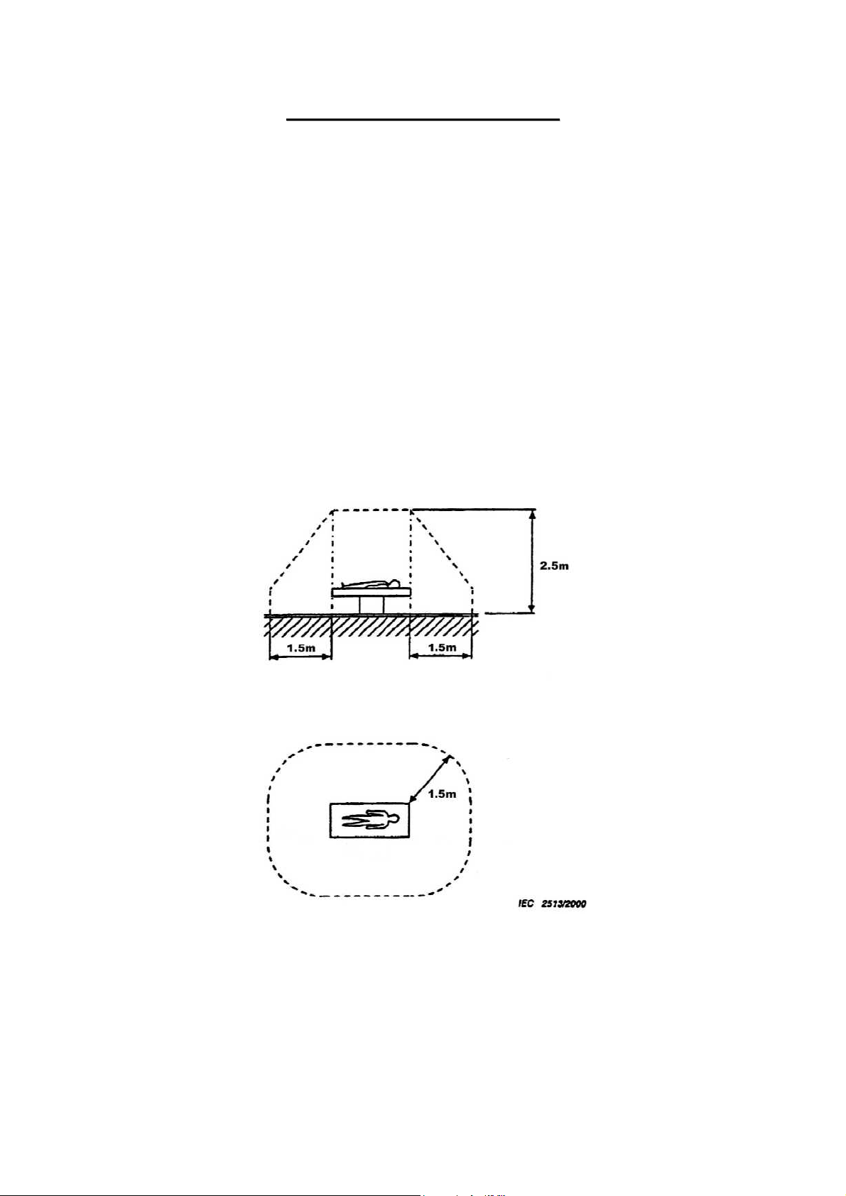
CCaauuttiioonn RReeggaarrddiinngg tthhee SSeettuupp
According to “IEC60601-1-1:2000”, devices installed in the patient environment are restricted
to “electric medical devices conforming to IEC60601-1”.
The Control PC and operation unit are classified under the data processing device standard
(IEC60950), therefore these items should not be installed in the patient environment.
The patient environment described below is an example cited from “IEC60601-1-1:2000” – the
measurements are only guidelines. However, the “IEC60601-1-1:2000” example must be treated
as the standard.
Therefore, the Control PC and operation unit must be installed in a location further than the
measurements below (outside of the patient environment).
*Areas where the patient moves (not only during imaging but when entering and leaving
the room, etc.) are also considered as part of the patient environment, therefore the
installation location should be determined upon consultation with the user regarding
areas outside of the patient environment.
Example of patient environment
Note: These measurements are only guidelines.

C
Copyright(C) Canon Inc. Medical Technical Service Dept. All rights reserved.
C
X
X
1..
1
DII--
D
G
G
Canon Inc. Japan
5
5
e
e
5
5
n
n
G//
G
err
e
5
5
all
a
Printed by Canon
Jun. 2009 Rev. 01
5
C
5
C

CONTENTS
General ............................................................................................................................. 1
1. CXDI-1 System Block Diagram .................................................................................. 2
2. System Diagram ........................................................................................................... 3
2.1 Standalone System .................................................................................................. 3
2.2 Total System ........................................................................................................ 3
3. CXDI Image Processing............................................................................................... 4
3.1 Process Flow ........................................................................................................... 4
3.2 Image Types ............................................................................................................ 4
4. Specifications ...............................................................................................................5

1. General
General
CXDI-55G / CXDI-55C
CXDI-55G/55C represents a thin and lightweight advanced cassette model with a large imaging size
that enhances users conveniences in portable digital radiography. It adopts the detachable connector,
which is compatible with the CXDI-60G/60C, allowing the use of two sizes portable flat panel
detector.
The vertical scanning drive (Drv-IC), the data read out and the AD conversion (Amp-IC) are located
in one side of LANMIT. Image data was read out from one direction.
The appearance of the CXDI-50G is almost the same as that of the CXDI-50C, but their fluorescence
substances are different.
CXDI System Software Ver.7.2 and later
55G Imaging Unit Serial Number 100001 and later
55C Imaging Unit Serial Number 100001 and later
Notes on usage
From the view of risk management, guarantee is not made for the waterproofing for blood and
chemicals, hygienic safety in operating room, usage with a defibrillation device in ICU, outdoor
usage or application to animals. If the sensor unit needs to be used under such condition, the system
integrator should be responsible for the operation and understanding of the tolerance of the product
specification.
1
1 CXDI System Block Diagram
AC100/120V/230V
CA1
X-Ray Generator
Symbol Description Remarks
CA1 AC Cable 3m
CA2 Sensor Cable 6.3m
CA3 X-Ray I/F Cable 20m
CA4 LAN Cable (Category 5)
CA5 LAN Cable (Category 5)
CA6 Serial Cable (Touch Panel)
CA7 VGA Cable
CA8 AC Cable 3m
Power Box
AC Power IN
X-Ray
I/F
CA3
OUT PUT 1
Control/Signal/
Power
OUT PUT 2
Control/Signal
Remote Switch
CA2
CA4
Printer
Image diagnosis
W/S
Image file device
1. General
Network
Ethernet
(100/10bese-T)
CA5
Imaging Unit
(CXDI―55G/55C)
Control/Signal
/Power
Control PC
LAN2
LAN1
AC100V~240V±10% 50/60Hz 2.2A
SERIA1(COM1)
VGA
SERIAL(COM2)
MOUSE
KEY BOARD
AC Power IN
CA8
CA6
CA7
RS232C
VGA
Mouse
Key Board
Operation
Unit
2
2 System Diagram
2.1 Standalone System
Standalone System Block Diagram
Patient Circumstances or Medical Room
CXDI55G /55C
AC or DC IN
Protective
Grounding
Power Box
Power Supply
1st / 2nd
AC250V
Insulation with
reinforcement
Recommended general PC
Basic Insula tion
General HUB
FC-E21 A
AC250V
or
1. General
Control/Signal
Ethernet
(1)
*
SELV
Control/Signal
Control
Control/Signal
Connector
Imaging Unit
(2)
Remote Switch
X-ray Generator
(601Compatible)
* SELV = Safety Extra-Low Voltage
Grid Unit
2.2 Total System
It can be connect to (1) and (2) of the system where the existing products have already been
connected. Extend the ethernet port by general switching HUB or ethernet card. The maximum
number of connections is limited to four by the control software specification.
Total System Block Diagram (Example)
Patient Circumstances or Medical Room
CXDI55G /55C
AC or DC IN
Protective
Grounding
CXDI-40E
Imaging Unit
Power Box
Power Supply
1st/2nd
AC250V
Insulation
with rei nforcemen t
Power Box
Control/Signal
Ethernet
AC250V
Basic Insulation
Control/Signal
Ethernet
General HUB
FC-E21 A
or
Recommended general PC
SELV
Control/Signal
Control
Control/Signal
Power Box
Ethernet
*
Control/Signal
Ethernet
Connector
CXDI-50
Imaging Unit
Imaging Unit
Remote Switch
X-ray generator
(601 Compatible)
*SELV = Safety Extra-Low Voltagej
Image Examination WS
Image File Equipment
Printer etc.
Grid Unit
3
3. CXDI Image Processing
1. General
3.1 Proccess Flow
Born image
Raw image
Original image
QA image
DICOM output
Diag. image
Processed image
Correction
processing
QA processing
Offset correction
Gain correction
Defect correction
dtstore
Characteristic extraction
• Sharpening
• DEP
• Gradation processing
MTF enhancement
•
(Frequency enhancement)
• Grid stripe reduction
• High density clipping
request
3.2 Image Types
(1) BORN IMAGE
The image obtained with LANMIT before any correction is made.
Outside distribution of these images is prohibited, including dtstore images.
(2) RAW IMAGE
Born image after offset processing, gain correction.
This is the image with LANMIT specific characteristics corrected.
(3) ORIGINAL IMAGE
Raw image after preprocessing.
(4) QA IMAGE
Original image after gradation processing, sharpening, and other processing.
The CXDI performs image processing up to this point.
(5) DIAG. IMAGE
QA image after further image processing necessary for diagnosis.
Image processed by the user for diagnostic purposes.
(6) PROCESSED IMAGE
Diagnosis image after post-processing.
Image modified by the user or the default processed image.
4

1. General
4. Specifications
The CXDI-55G/55C (Imaging Unit/Power Box) is the Digital Cassette that has the mobility and
can be used on the optional angles.
(1) Imaging Unit
This unit consists of the internal sensor, PWB-Di Board, PCB-REF Board, and its outer
cover. The sensor unit converts the X-ray image to the electrical signal (O/E Conversion)
and after performs the A/D conversion, transfer its signal through the Power Box with
Ethernet cable to the Control PC.
Item 55G 55C Remarks
Object General Shooting Cassette
Effective filming range 353 x 430mm
Number of Pixels 2220 x 2706
Effective Number of Pixels 2208 x 2688
Pixel pitch
Fluorescent substance GOS Fluorescent screen CsI one panel
Output gradations
Transfer method
Imaging cycle 15 sec. (standard)
Image display time 3 sec. (thumbnail)
Dimension
Imaging Unit coloring Cool white
Imaging Unit mass
Space between surface where
patient gets in contact (CFRP)
and sensor surface (glass)
Remote SW OFF
emission
Consumpt
-ion
Power Control
(ON/OFF)
Mechanical strength
Control PC
Grid attach/remove detector Yes
Sensor cable S150-55
Sensor cable S630
Count of connected sensor
Max load mode 115kcal/h
Remote SW OFF
Max load mode 32W
160µm x 160µm
12bit (4,096 gradations)
A/D 14bit
Ethernet: Imaging Unit to
Control PC
(Through the Power Box)
8 sec. (full size image)
480 (W) x 481 (D) x 15 (H)
3.4 Kg
3.7 Kg
36kcal/h
11W
None
The Imaging unit is put on the plain surface with
the Sensor side (Detector) is up.
Load uniformly: 150Kg
• FC-E21A for CXDI
• Standard desktop
Detachable connector
cable on the sensor side
Detachable connector
cable on the power box
side
• 4 possible connections
• Maximum of three
• Each Imaging unit
mm
4.5mm
Load partly: 100Kg/φ40mm
ControlStation
computer with the
same performance
as the FC-E21A
to the Control PC1
(via HUB)
same type sensor can
be connected to a
control PC
works in pair with a
Power Box
Å
Å
Å
Å
Å
Å
Å
Å
Å
Å
Å
Å
Å
Å
Å
Å
Å
Å
Å
Å
Å
Å
Å
Å
(Mobile/Desktop PC)
Except the cable
With 1.5m cable
Heat
1 image per 15 Sec.
Power
1 image per 15 Sec.
Power Box: Operation with Remote switch
manually
Self-restriction
1.5m
6.3m
HUB shall be procured by each sales
company.
5

Item 55G 55C Remarks
Scattered radiation backward
block sheet
Environment-conscious
Mo sheet (0.3 mm thick)
unleaded type
Photo timer Cannot be built in
Imaging restriction
(Imaging Prohibition)
User interface
When the internal
temperature of Imaging Unit
is above 49 degree Celsius,
its state is changed to sleep
mode. And the Imaging
prohibition will be continued
when the internal
temperature is below 48
degree Celsius.
On in blue: Imaging unit
power is on.
Blinking in blue: Imaging
unit power is off.
On in orange: Imaging unit is
busy.
Blinking in green: Preparing
imaging/error status.
On in green: Imaging
preparation is complete.
1. General
Å
Å
Å
Å
INDICATION BUSY SENSOR POWER
Color Orange*5 Green Blue
Imaging unit
is off
Imaging unit
is on
Preparing
imaging
Imaging
preparation
complete
Error status -- Blinking
Communicating
Initialization
(when
startup)
Network not
set (when
startup)
*1: Turns on and off for 0.5 seconds each
*2: Turns on and off twice for 0.5 seconds, then
turns off for 0.5 seconds
*3: Turns on and off randomly
*4: Fades in for 1 second and fades out for 1
second
*5: Turns on in green for China products.
Off Off Off
-- Off On
*1
-- Blinking
-- On On
*3
-- On
On
-- Blinking
-- Blinking
On
*2
On
*3
On
*4
On
6

1. General
(2)Power Box
This unit consists of PWB-60XRAY Board, 60 Sensor Power Supply unit and outer covers.
The function; the signal transition between Imaging unit and Control PC, the interface to the
X-ray generator equipment and power supply to the Imaging unit has been implemented.
Item Content Remarks
Communication
interface standard for
IEEEE 802.3u (100BASE-TX)
*6
Connector type: RJ45
control PC
Communication method
with PWB-60XRAY
Asynchronous serial communication
method
Data length: 10bit
Data rate: 15.625 kHz
Reference
Power supply AC 100-240V 50/60Hz 1.2A-0.7A
60 Sensor Power Supply
Rated Voltage:
AC 100-240V (AC 85-264V)
Mass 3.7 Kg
Except bottom rubber parts
Dimension 358(W) x 200(D) x 65(H)* mm
(With bottom rubber parts:
75mm)
(3) Environment rated parameters
Item Content Remarks
Operating temperature
+5 to +35°C
Operating humidity 30 to 75% RH
Keeping or
Transporting
Temperature: -30 to +50°C
Humidity: 10 to 60% RH
Atmospheric pressure: 700 to 1060 hPa
Must be without dewing
7

M
M
C
Copyright(C) Canon Inc. Medical Technical Service Dept. All rights reserved.
X
C
X
2.. II
2
DII--
D
nsstt
n
a
a
Canon Inc. Japan
5
5
5
5
allll
a
n
u
n
u
G//
G
attii
a
all
a
5
5
Printed by Canon
Jun. 2009 Rev. 01
5
C
5
C
o
n
o
n

Contents
1 Caution During the Installation....................................................................................................1
2 Restrictions on Installation ..........................................................................................................1
3 Caution on Installation.................................................................................................................2
4 Product Configuration..................................................................................................................3
4.1 Product Configuration List ..................................................................................................3
4.2 Configuration.......................................................................................................................4
4.3 Sensor Cable (Optional) ......................................................................................................5
5 Packing Diagram .........................................................................................................................6
5.1 X-ray Digital Radiography System (CXDI-55G/55C) ........................................................6
5.2 Grid Frame (Optional) .........................................................................................................8
6 Installation Procedures.................................................................................................................9
6.1 Lists of Tools Needed for Installation .................................................................................9
6.2 System Installation Procedures..........................................................................................10
7 Installation .................................................................................................................................12
7.1 Connection to Each Unit....................................................................................................12
7.1.1 Connection Diagram ................................................................................................12
7.1.2 Connecting to the Power Box ..................................................................................13
7.1.3 Using the Sensor Unit in the Multiple Rooms.........................................................19
7.1.4 Interchanging a Sensor Unit ....................................................................................20
7.1.5 Sensor Cable (Optional)...........................................................................................22
7.1.6 Connection Diagram for Control PC Rear Panel.....................................................23
7.1.7 Adjusting the Length of the X-ray I/F Cable ...........................................................24
7.2 Starting up and Shutting down the System........................................................................25
7.2.1 Sequence for Starting up the System .......................................................................25
7.2.2 Sequence for Turning the Power off........................................................................25
7.3 X-ray Controller Interface .................................................................................................26
7.3.1 Interface Signal Description ....................................................................................26
7.3.2 Signal Names and Functions in the Connection with the X-ray Generator .............28
7.3.3 Rating and Characteristics for Relay and Photo Coupler (on PWB-XRAY)...........30
7.4 Network Settings ...............................................................................................................32
7.5 Setting the Fixed ROI Areas..............................................................................................35
7.6 Adjusting the Phototimer...................................................................................................38
7.7 Settings ..............................................................................................................................40
7.8 Adjusting the Alignment ...................................................................................................97
7.9 Image Quality ..................................................................................................................103
7.10 Post-installation Checks...................................................................................................105
8 Dimension................................................................................................................................107

2. Installation
1 Caution during the installation
Please pay attention to the followings when installing the system.
(1) If the equipment is hoisted, lowered or transported, it must be supported at both sides by a
minimum of two people so there is no danger of it falling.
(2) When installing the equipment, be sure the site meets the following criteria:
1) There must be no dripping water in the area.
2) The environment must be free of harmful elements such as humid or acidic air, air with
a saline or sulfur content, where there is poor ventilation or where air pressure or
temperature is unusual.
3) The equipment must not be placed at an angle or subjected to vibration or shock (this
includes during transportation).
4) The equipment must not be kept where chemical products are stored or where gasses are
generated.
5) The site’s power supply must be of the correct voltage and frequency for the equipment.
6) The site must be connected to a fully earthed cable with sufficient ground resistance to
meet standard values.
(3) After installation, be sure to dispose of waste product packaging with care and with full respect
for the environment.
2 Restrictions on Installation
(1) A clearance of at least 150mm must be left between a sensor unit and power box.
(2) It is forbidden to use the cables (sensor cable, X-ray interface cable, etc.) from the power box
for moving parts. The only exception to this restriction is the sensor cable that is to be
connected to the sensor unit.
- 1 -

2. Installation
3 Caution on Installation
(1) Do not install the sensor near electronic devices as noises and artifacts tend to appear on
images in the electromagnetic field.
e.g. CRT monitor, X-ray generator, and any other medical electronic devices.
(2) Follow the following steps to detach the sensor cable while the system is running.
1) To detach the sensor cable
- Check the LED of the sensor unit and the display of the control PC to make sure the
status of communication between the imaging unit and Control PC is idle. (*1)
- Turn off the main power switch of the power box or the remote switch. (*2)
- Make sure the LED on the imaging unit, switch on the power box and remote switch
are turned off. Power supply to the Imaging unit must be disconnected.
- Detach the connector of the sensor cable.
*1: Do not detach the sensor cable during the data transmission between the sensor unit
and control PC, it may cause equipment breakdown.
*2: Do not detach the sensor cable when the power is being supplied from the power box,
it may cause equipment breakdown. If you disconnect the sensor by improper steps, the
“Error” LED on the power box and remote switch will be turned on to alert you the
sensor cable is detached improperly. To restore from the error, turn off the main switch
of the power box or the remote switch. Then connect the sensor cable again by
following the steps described in the next column.
2) To attach the sensor cable
- Make sure the LED on the imaging unit, switch on the power box and remote switch
are turned off. Power supply to the Imaging unit must be disconnected.
- Connect the connector of the sensor cable.
- Turn on both the main switch of the power box and remote switch.
(3) Before proceeding with installation, ensure that the static accumulated in the bodies of the
installation personnel is discharged. Similarly, before touching the PCBs (when removing
them) or cable connectors, ensure that all static is discharged.
- 2 -
2. Installation
4 Product Configuration
4.1 Product Configuration List
1) CXDI-55G/55C
No. Item Name Qty Remarks
with 1.5 m sensor cable
1 CXDI-55G/55C Imaging Unit 1
2 Sensor cable P630 (on the power box side) 1 6.3m
3 Operation manual (for imaging unit) -
4 Attached documents for medical - (JPN)
5 Warranty registration - (JPN)
6 Warranty card - (US)
7 German Security leaflet/WEEE leaflet - (EU)
2) CXDI SYSTEM II
No. Item Name Qty Remarks
1 Power Box 1
2 X-ray I/F cable 1 20m
3 Remote switch 1 20m
4 Power supply cable (with AC plug) 1 3m (100/120/230V)
5 Operation manual (for power box) -
3) Sensor Cable (Optional)
No. Item Name Qty Remarks
Sensor Cable P630-PM
1
(Panel mount type)
Sensor Cable SP780-55
2
(Straight type)
LAN cable for connecting Control PC / Power Box and Network switch (Switching HUB) for
connecting the multiple Imaging Units shall be procured at each sales company.
S150-55 (sensor side)
attached.
1 6.3m
1 7.8 m
- LAN cable (Over category 5)
Recommended length of the cable is 30m or less.
When Control PC and Power Box are connected directly, Cross type is used, but when they
are connected via Network switch, Straight type is used. However, this is not applied when
Network switch has AUTO-MDI/MDI-X function*.
- Network switch (Switching HUB)
Sales companies adopt Network switch (Switching HUB) after conducting the test and the
operation check for Switching HUB that meets the general standard.
- 3 -
2. Installation
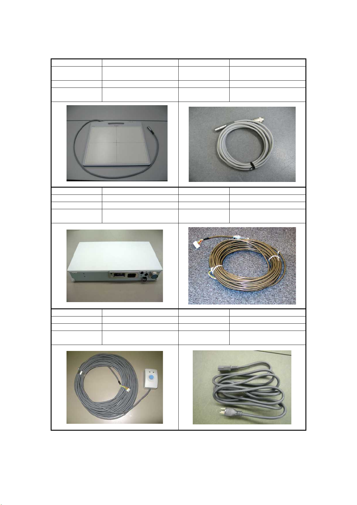
4.2 Configuration
No. 1 No. 2
Name
Qty 1 Qty 1
Remarks
No. 3 No. 4
Name Power Box Name X-ray I/F cable
Qty 1 Qty 1
Remarks I/F and Power supply Remarks
CXDI-55G/55C Imaging Unit
With the sensor cable
S150-55 (imaging unit side)
Name
Remarks 6.3m
Sensor cable P630
(Power box side)
Connection with X-ray
generator
No. 5 No. 6
Name Remote switch Name Power supply cable
Qty 1 Qty 1
Remarks
Switch to turn on and off
Power Box
Remarks
For Power Box
(100/120/230V each type)
- 4 -
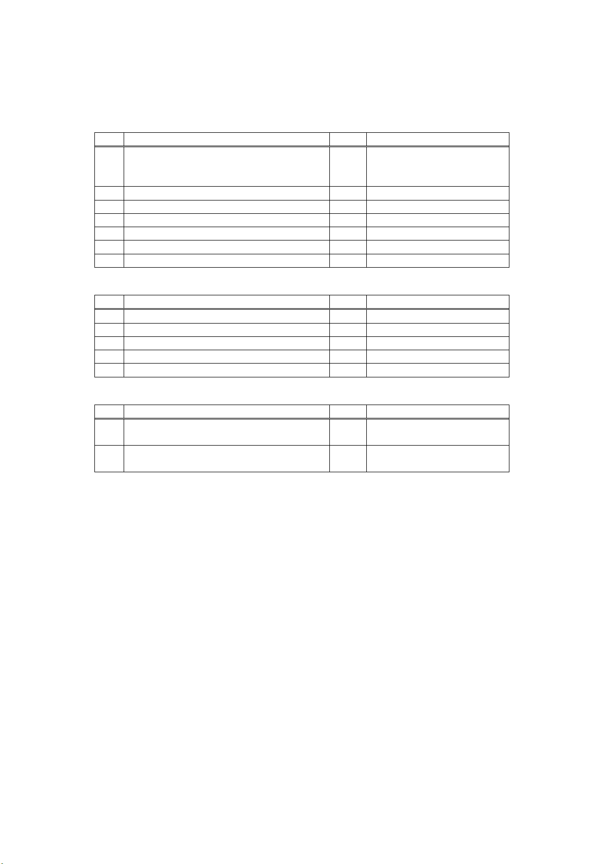
4.3 Sensor Cable (Optional)
No. 1 No. 2
Name
Qty 1 Qty 1
Remarks
Sensor Cable P630-PM
(Panel mount type)
6.3m
Detachable cable connector
2. Installation
Remarks
Name
Sensor cable SP780-55
(Straight type)
7.8m
Non-detachable cable
Sensor cable P630-PM (panel mount type)
This sensor can be used instead of a standard sensor cable P630 (power box side). Only the
difference is the form of the connector. There is no difference in the function of the cable.
Sensor cable SP780-55 (straight type)
This is a single straight type sensor cable with no detachable connectors. This single cable can be
used instead of the sensor cable S150-55 (sensor side) and sensor cable P630 (power box side).
There is no difference in the function of the cable.
- 5 -
22.. IInnssttaallllaattiioon
n
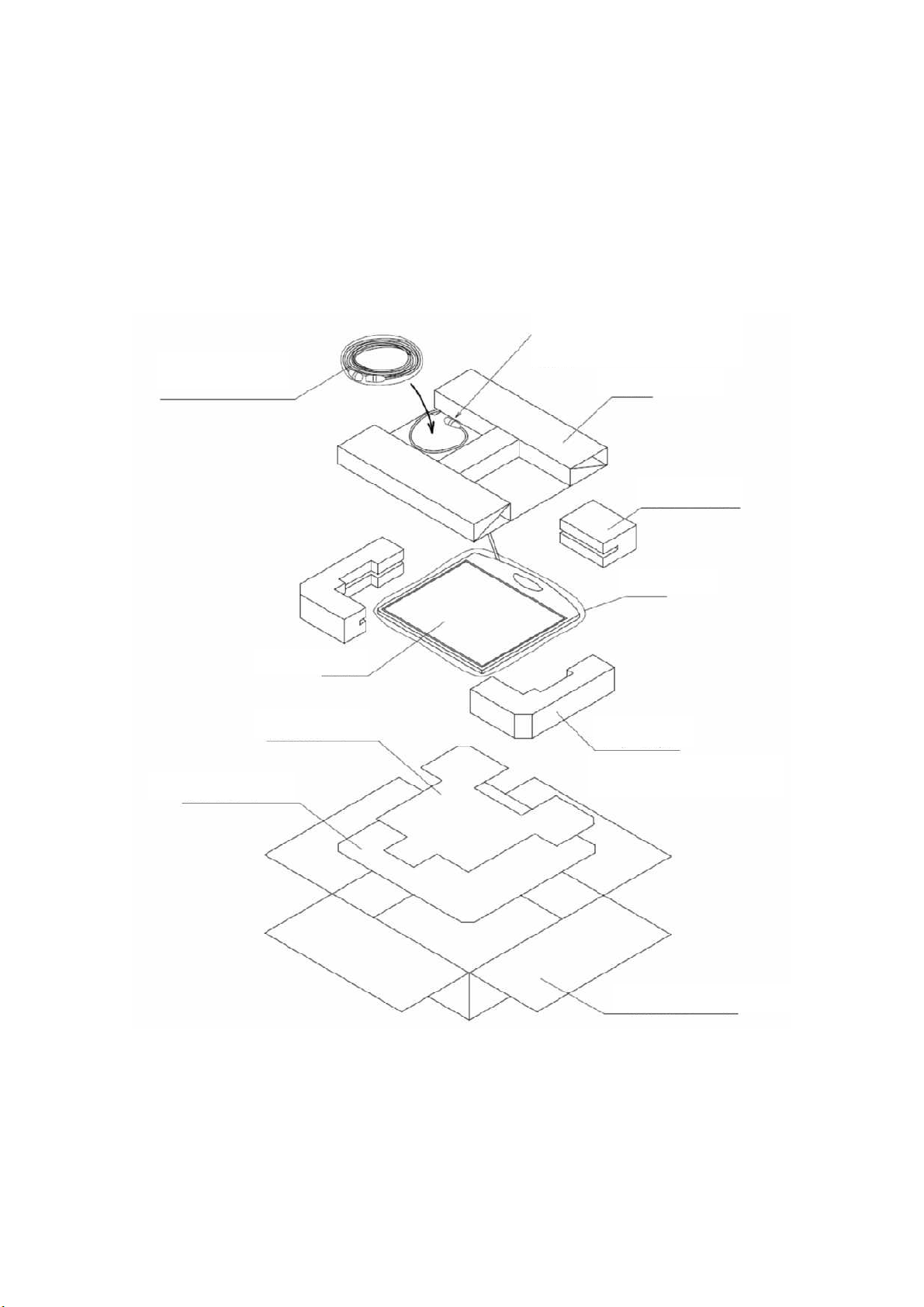
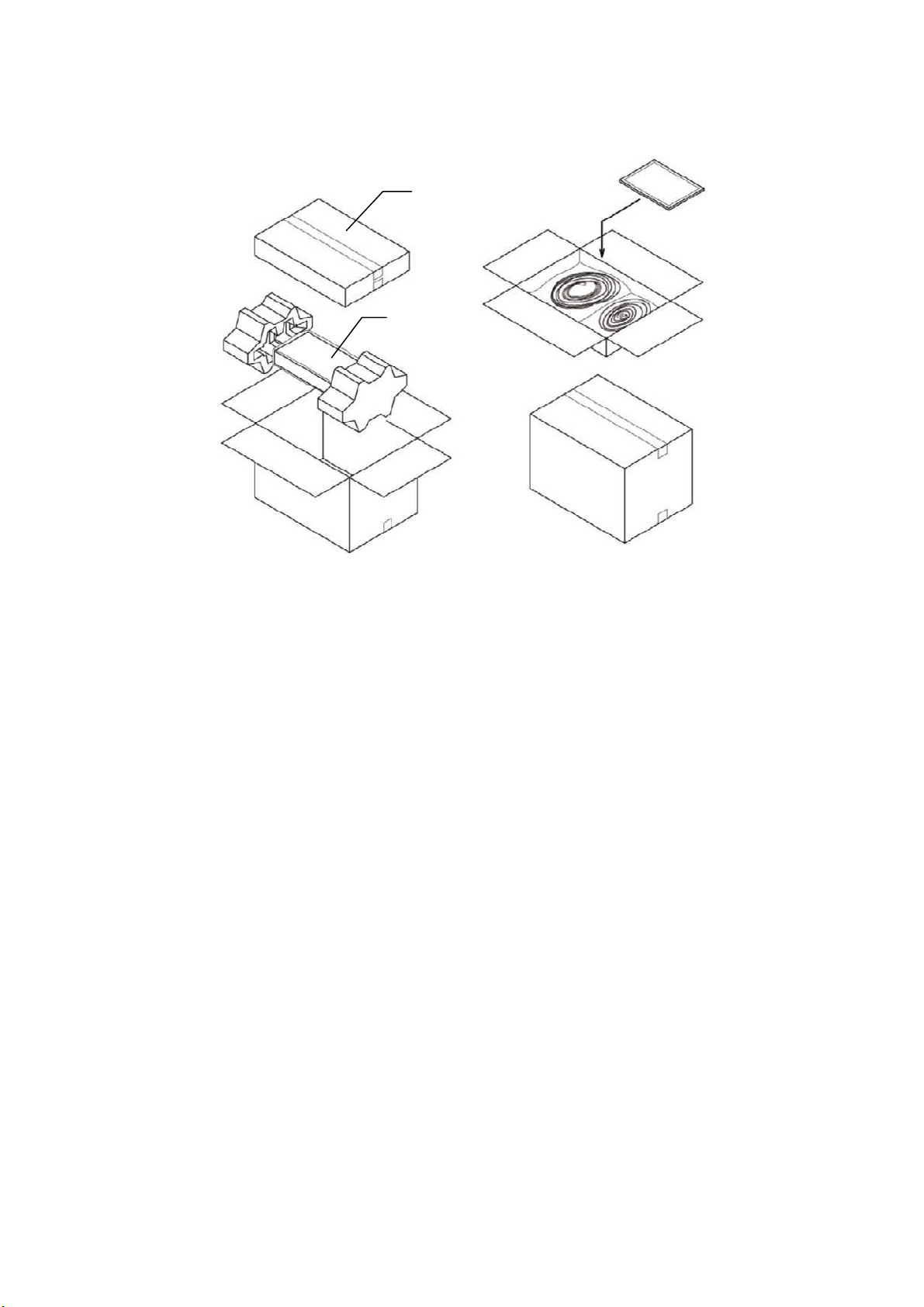
5 Packing Diagram
5.1 X-ray Digital Radiography System (CXDI-55G/55C)
(1) CXDI-55G/55C Imaging Unit Package
Sensor cable P630
(6.3m)
Place the sensor cable S150-55
on the packet corner of the paper
tube
Paper tube
Center pad
Plastic bag
Imaging Unit
Positioning sheet
Cardboard sheet
Corner pad
Common to right and left
Cardboard box for imaging unit
- 6 -
22.. IInnssttaallllaattiioon
(2) CXDI System II Assembly Package
Power box
Accessories box
n
- 7 -
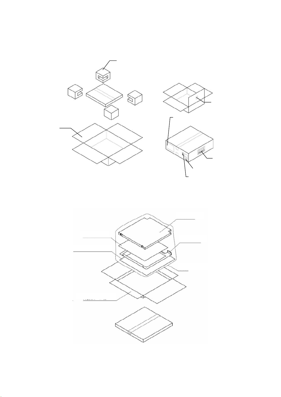
5.2 Grid Frame (Optional)
(1) Outer Packaging
Outer package
(2) Inner Packaging
22.. IInnssttaallllaattiioon
Corner packing
n
Material label
Product division label
Handle with care
label
Origin label
Shipping
environment
label
Protection sheet
Dummy sheet
Protection sheet
Inner Package
Grid frame
Plastic bag
- 8 -

2. Installation
6 Installation Procedures
6.1 Lists of Tools Needed for Installation
No. Tool Name Unit Remarks
1. General Tools 1 set JIS Screwdriver set
2. Note PC 1
3. LAN Card 1 For Note PC (as required)
4. Mouse 1 PS/2 type
5. Keyboard 1 PS/2 type
6. HUB 1 Connection between Control PC and Note PC
7. 10/100BASE-TX cable 2 Straight type (Control PC to Note PC)
CXDI Software version
8.
compatibility table
Mirror, oil-based
9.
marker and paper etc.
PC/AT compatible
(OS: Microsoft Windows XP Professional recommend)
-
1 For adjusting the alignment with the X-ray tube.
- 9 -

2. Installation
6.2 System Installation Procedures
No. Step Conditions and Checkpoints Reference Section
1 Unpacking and checking
the product’s constituent
parts
2 Connect the Imaging Unit
and the Power Box
3 Connect the Power Box
and the Control PC
4 Connect the Power Box
and the X-ray generators
5 Check date and time - Date and time must be changed
6 Check the software
program’s version
7 Identifying the Imaging
Unit (input the sensor
serial numbers)
8 Enter control PC serial
number.
(9) Adjusting the timing with
X-ray generator
10 Calibration -No error must be displayed. Operation Manual
11 Setting the Fixed ROI
Areas
12 Set exposure parameter
table
13 Set annotation -Set it in consultation with the technician. “(9) Performing the
14 Connect the network and
set the output destination
15 Startup settings “(5) Set Up Startup
-There must be no missing parts,
damage, dents, etc.
-There must no color changes in the
shock sensor.
-Handle the instrument carefully, as it
may be damaged if something is hit
against it, dropped or receives the strong
jolt.
-The cable must be routed in such a way
that no unreasonable loads are brought to
bear upon them.
-The cable must be routed in such a way
that no unreasonable loads are brought to
bear upon them.
-The manufacturer of the X-ray
generators must be asked to handle the
connections with the generators.
according to the area where the
instrument is installed.
-The compatibility of the sensor unit and
the Control PC must be checked on the
compatibility list, and the software
program must be installed or upgrade as
required.
-No required usually.
If necessary, set the ROI area.
-Set it in consultation with the technician. “(8) Table Setup
“(10) Network
“(1) Checking and
Setting the Date and
Time” in section
7.6.
“(2) Checking the
Firmware Version”
in section 7.6.
“(6) Identifying the
Sensor Units” in
section 7.6.
“(7) Entering
Control PC Serial
Number” in section
7.6.
Setting” in section
7.6.
Annotation Setting”
in section 7.6.
Connections” in
section 7.6.
Menu” in section
7.6.
- 10 -

2. Installation
No. Step Conditions and Checkpoints Reference Section
16 Exposure testing -The data must be sent to the printer and
storage and the image quality must be
checked.
17 Check the linearity of the
transferred image density.
18 Operation unit Gamma
correction
19 Body parts settings -Set it in consultation with the technician. Operation Manual
20 Check and set the system
settings.
21 Total adjustments and
delete the unnecessary
data.
22 Cleaning
23 Explain the operation to
the user
24 Final parameter
adjustment
25 Inserting the backup
floppy disk.
26 Back up valuable data -Copy the CCR folder to the removal
“(11) Linearity
“(12) Operation
-Set it in consultation with the technician. Each section in
-Conform according to the check sheet.
-Delete the unnecessary data.
Operation Manual
-Consult with the technician to narrow
down the adjustments to the final values.
-It must be confirmed at re-start that
backup files have been made.
-No necessary for the system installed in
vehicles.
drive.
Section 5.7 Image
Quality.
Check Image
Density” in section
7.6.
Unit Gamma
Correction” in
section 7.6.
section 7.6.
Settings.
Section 7.9
Post-installation
check.
Operation Manual
“(15) Backing up
Setting Data to FD”
in section 7.6.
“(14) Backing Up
when Installing” in
section 7.6.
- 11 -
2. Installation Manual
7 Installation
7.1 Connection to Each Unit
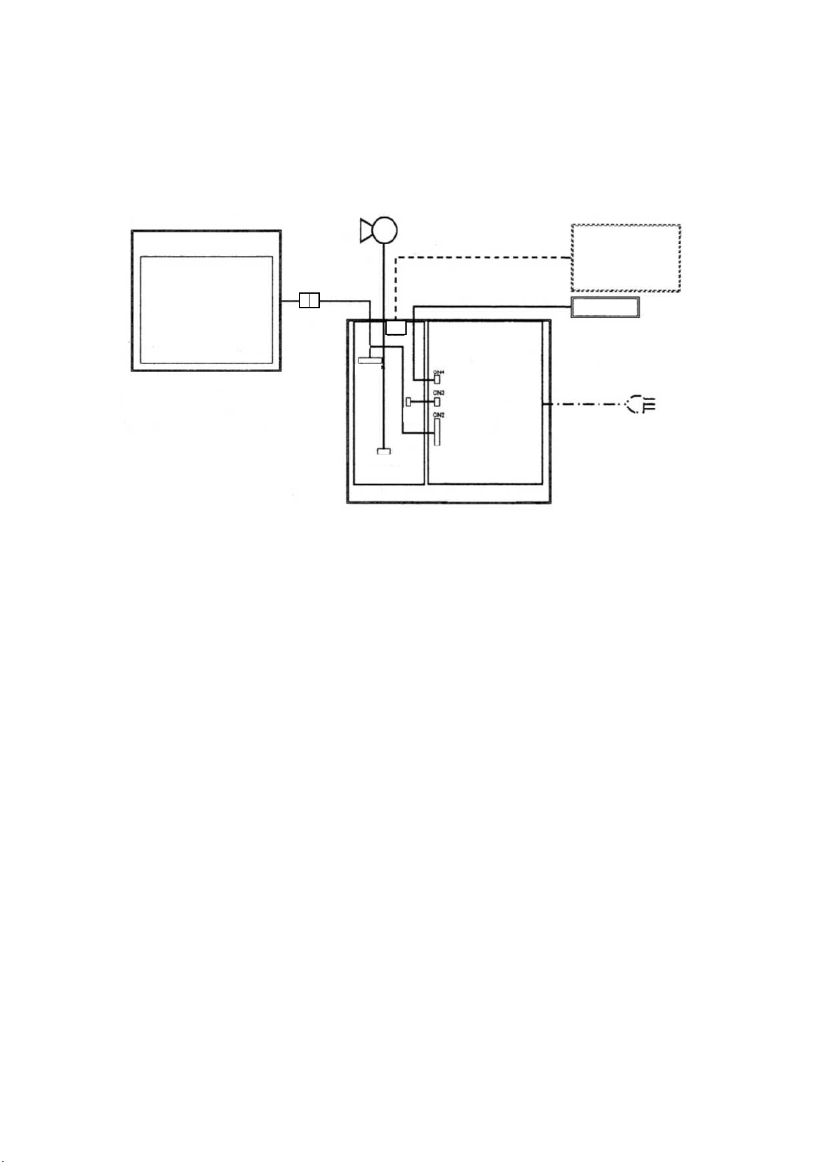
7.1.1 Connection Diagram
Control PC
CXDI-55G/55C
J1
J2
J3
J4
PWB-XRAY
POWER BOX
Remote Switch
POWER SUPPLY
- 12 -
2. Installation
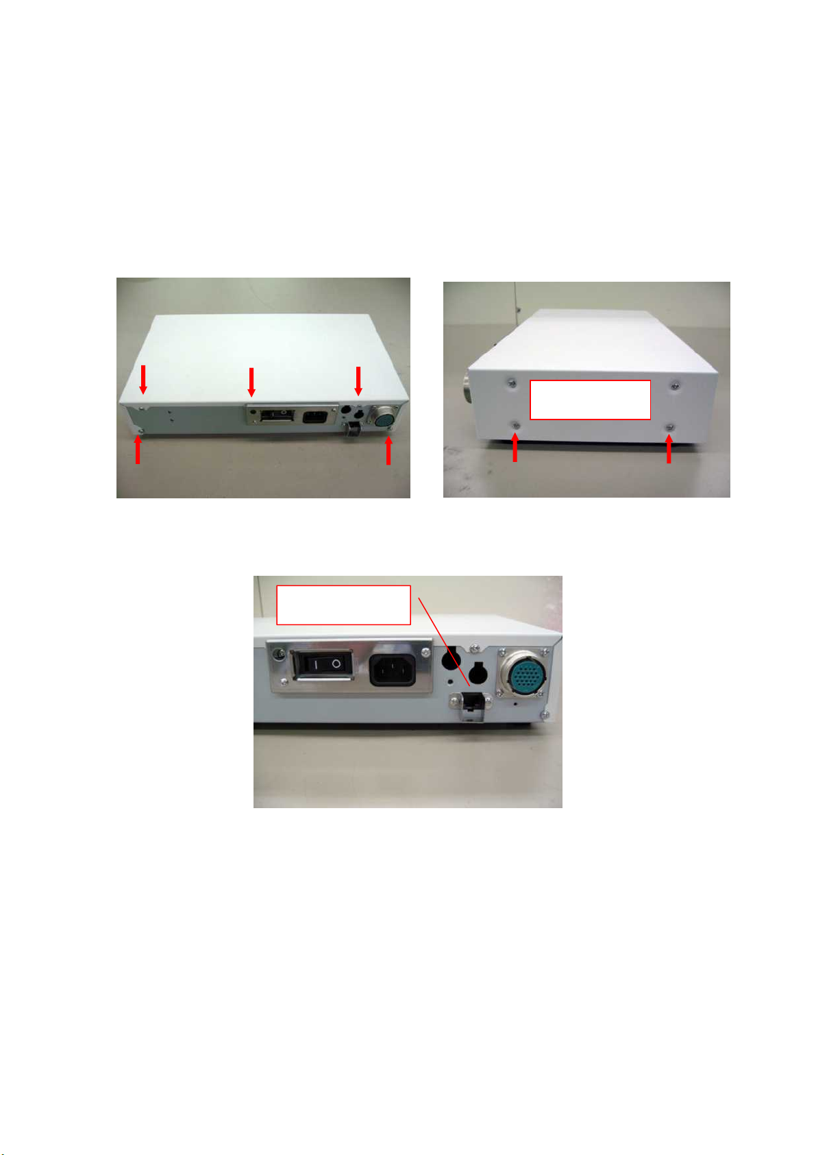
7.1.2 Connecting to the Power Box
(1) Removing the cover
1) Remove the 5 screws from the back of the power box and the 2 screws on each side at the
bottom of the power box to remove the top cover.
Different types of screw are used for backside and lateral side. Make sure to use the proper type
of screw respectively on installation.
Also remove screws on
the far side
2) Before connecting the X-ray I/F cable and remote cable, remove the LAN cable connector
guard to avoid injury.
LAN cable connector guard
- 13 -
(2) Cable connections
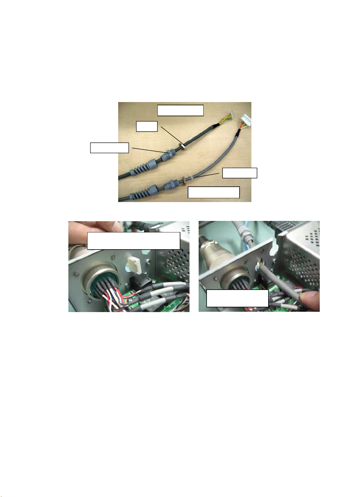
1) Loosen the skin top spiral and lock nut of the remote cable and X-ray I/F cable. Do not
remove the insulation lock from the X-ray I/F cable as it is put on the cable to prevent the
cable from falling off.
*The X-ray I/F cable is 20m in length. If the cable is too long, you may need to make it shorter.
Refer to “7.1.4. Adjusting the length of X-ray I/F cable” for details.
Skin top spiral
2) Get the connector and lock nut of the remote cable through the hole in a power box.
2. Installation
Remote Cable
Lock nut
Insulation lock
X-ray I/F Cable
Adjust the direction of the connector
to the notch of a hole.
Get the lock nut through
the hole.
- 14 -
 Loading...