

Page 1
J
E
INSTRUCTION
MANUAL
1
Page 2

Introduction
The Canon Speedlite 470EX-AI is an EOS-dedicated external
Speedlite, compatible with E-TTL II/E-TTL autoflash systems. The
Speedlite can be used as an on-camera flash that attaches to the hot
shoe of the camera (normal flash photography), and as a receiver unit
during optical transmission wireless flash photography. Note that,
during normal flash photography, the Speedlite can be used for AI
bounce flash photography.
Before Starting to Shoot, Be Sure to Read the Following
To avoid botched pictures and accidents, first read the “Safety
Precautions” (pages 8-9). Also, read this manual carefully to ensure that
you use the product correctly.
Read This Instruction Manual while also Referring to Your
Camera’s Instruction Manual
Before using the product, read this Instruction Manual and your
camera’s Instruction Manual to familiarize yourself with their operations.
Be sure to store this manual safely, too, so that you can refer to it again
when necessary.
Using the Speedlite with a Camera
Using with an EOS DIGITAL camera (Type-A camera)
You can use the Speedlite for easy flash photography using
autoflash control in the same way as a camera’s built-in flash.
Using with an EOS film camera
An EOS camera with E-TTL II/E-TTL autoflash metering
system (Type-A camera)
You can use the Speedlite for easy flash photography using
autoflash control in the same way as a camera’s built-in flash.
An EOS camera with TTL autoflash metering system (Type-B
camera)
See page 110.
* This Instruction Manual assumes that the Speedlite is used with a
Typ e -A ca m e ra.
2
Page 3

Chapters
Introduction
Getting Started and Basic Operations
1
2
3
4
5
6
7
Preparing for flash photography and basic flash photography
Advanced Flash Photography
Advanced shooting utilizing the flash functions
Bounce Flash Photography
Flash photography using the AI bounce flash functions and
bounce adapter
Setting Flash Functions with Camera Controls
Setting the flash functions from the camera’s menu screen
Wireless Flash Photography: Optical Transmission
Wireless (receiver) flash photography using optical transmission
Customizing the Speedlite
Customizing with Custom Functions and Personal Functions
Reference
System map, Troubleshooting guide, Using with a type-B camera
2
17
29
41
65
71
81
93
3
Page 4

Conventions Used in this Manual
Icons in this Manual
9 : Indicates the Select dial.
<H> <E>:<S> Indicates the top, bottom, left, and right
<I> <O> buttons of the cross keys.
8 : Indicates the Select/Set button.
p/2 : Indicates that the respective function remains
active for approx. 12 sec. or 16 sec. after you let
go of the button.
(p.**) : Reference page numbers for more information.
: Warning to prevent shooting problems.
: Supplemental information.
Basic Assumptions
The operation procedures assume that the Speedlite is attached to the
camera and that both are turned on.
The icons used for buttons, dials, and symbols in the text match the icons
found on the Speedlite and the camera.
The selection operation performed when setting a function basically
describes selecting a function by turning <9>. A selection can also be
made by pressing the top, bottom, left, and right (<H> <E>
<I> <O> buttons) of the <S> cross keys.
Pressing the <0> button returns the display to the previous screen.
The operation procedures assume that the Custom Functions and
Personal Functions of the Speedlite, and the menu and Custom
Functions of the camera are at their default settings.
All figures such as the number of flashes are based on the use of four
AA/LR6 alkaline batteries and Canon’s testing standards.
In this manual, the words “master” and “slave” used in previous manuals
have all been replaced by the words “sender” and “receiver” respectively.
Read the words “sender” and “receiver” in this manual for the above
meanings as necessary.
4
Page 5

Contents
Introduction 2
Chapters ...........................................................................................3
Conventions Used in this Manual .....................................................4
Contents............................................................................................5
Index to Features..............................................................................7
Safety Precautions............................................................................8
Nomenclature..................................................................................10
Getting Started and Basic Operations 17
1
Installing the Batteries.....................................................................18
Attaching and Detaching the Speedlite to and from the Camera....20
Turning on the Power......................................................................21
a: Fully Automatic Flash Photography ...................................24
E-TTL II/E-TTL Autoflash by Shooting Mode ..................................25
Advanced Flash Photography 29
2
f Flash Exposure Compensation .................................................30
7: FE Lock...................................................................................31
c High-speed sync ........................................................................32
r Second-curtain sync.................................................................33
H:Setting the Flash Coverage ...............................................34
a: Manual Flash............................................................................36
Modeling Flash................................................................................38
Clearing Speedlite Settings.............................................................40
5
Page 6

Contents
Bounce Flash Photography 41
3
X AI Bounce Flash .................................................................... 42
W AI.B Full-Auto........................................................................ 46
W AI.B Full-Auto Shooting ........................................................ 48
V AI.B Semi-Auto Shooting...................................................... 56
m Manual Bounce Flash Photography ........................................ 61
q Combined Use with the Bounce Adapter ............................... 63
Setting Flash Functions with Camera Controls 65
4
Flash Control from the Camera’s Menu Screen ............................. 66
Wireless Flash Photography: Optical Transmission 71
5
: Optical Transmission Wireless Flash Photography................. 72
Wireless Settings............................................................................ 74
a: Fully Automatic Wireless Flash Photography.................... 76
A Manual Flash Setting on a Receiver Unit ......................... 79
Customizing the Speedlite 81
6
C / >: Setting Custom and Personal Functions................... 82
C: Setting Custom Functions.................................................... 85
>: Setting Personal Functions................................................... 88
Reference 93
7
470EX-AI System........................................................................... 94
f Flash Firing Restrictions due to Temperature Increase ........... 96
Troubleshooting Guide................................................................... 98
Specifications ............................................................................... 105
Using with a Type-B Camera ....................................................... 110
Index............................................................................................. 113
6
Page 7

Index to Features
Power Source
Batteries Î p.18
Firing interval/count Î p.18
Power ON/OFF Î p.21
Flash ready Î p.21
Quick flash Î p.21
Auto power off Î p.22
Operations
Attaching and detaching
the Speedlite Î p.20
Lock function Î p.22
LCD panel illumination Î p.22
Normal Flash Photography
E-TTL autoflash Î p.24
Autoflash by shooting
mode Î p.25
Manual flash Î p.36
Metered manual
flash Î p.37
TTL autoflash Î p.110
Functions
Flash exposure
compensation Î p.30
FE lock Î p.31
High-speed sync Î p.32
Second-curtain sync Î p.33
Modeling flash Î p.38
AF-assist beam Î p.27
Flash coverage Î p.34
• Wide panel Î p.35
Clearing settings
(Reverting to defaults) Î p.40
Flash function settings Î p.65
Flash firing restriction Î p.96
Typ e-B c am e ra Î p.110
Bounce Flash Photography
AI.B full-auto Î p.43
AI.B semi-auto Î p.45
Manual bounce Î p.61
Bounce adapter Î p.63
Optical Transmission Wireless
Flash Photography
E-TTL autoflash Î p.76
Memory function Î p.75
Individual receiver Î p.79
Customization
Custom Functions (C.Fn) Î p.85
Personal Functions (P.Fn)
Clear all Î p.84
Î p.88
7
Page 8

Safety Precautions
The following precautions are provided to prevent harm or injury to
yourself and others. Make sure to thoroughly understand and follow
these precautions before using the product.
If you experience any malfunctions, problems, or damage to the
product, contact the nearest Canon Service Center or the dealer
from whom you purchased the product.
Warnings:
To prevent fire, excessive heat, chemical leakage, explosions, and electrical shock,
follow the safeguards below:
• Do not insert any foreign metallic objects into the electrical contacts of the product,
accessories, connecting cables, etc.
• Do not use any batteries, power sources, or accessories not specified in the
Instruction Manual. Do not use any deformed or modified batteries, or the product
if it is damaged.
• Do not short-circuit, disassemble, or modify the product or batteries. Do not apply
heat or solder to the batteries. Do not expose the batteries to fire or water. Do not
subject the batteries to strong physical shock.
• Do not insert any battery’s plus and minus ends incorrectly, or mix new batteries
with used ones or batteries of different type.
Do not use the product in locations where there is flammable gas. This is to prevent
an explosion or a fire.
Do not fire the flash at anyone driving a car or other vehicle. It may cause an accident.
Do not disassemble or modify the equipment. High-voltage internal parts may cause
electrical shock.
If you drop the equipment and the casing breaks open to expose the internal parts,
do not touch the exposed parts. There is a possibility of an electrical shock.
Do not store the product in dusty or humid places or location with lots of oil smoke.
This is to prevent a fire or electrical shock.
Before using this product inside an airplane or hospital, check if it is allowed.
Electromagnetic waves emitted by the product may interfere with the plane’s
instruments or the hospital’s medical equipment.
If a battery leaks, changes color, deforms, or emits smoke or fumes, remove it
immediately. Be careful not to get burned in the process. It may cause a fire,
electrical shock or burns if you keep using it.
Keep the batteries and other accessories out of the reach of children and infants. If a
child or infant swallows a battery or accessory, consult a physician immediately.
(Battery chemicals may harm the stomach and intestines.)
Be careful not to get the product wet. If you drop the product in the water or if water
or metal get inside the product, promptly remove the batteries. This is to prevent fire,
electrical shock, and burns.
Do not cover or wrap the product with a cloth. Doing so may trap heat within and
cause the casing to deform or catch fire.
Follow the warnings below. Otherwise, death or
serious injuries may result.
8
Page 9
Safety Precautions
Keep the equipment out of the reach of children and infants, including when in use.
Straps or cords may accidentally cause choking, electrical shock, or injury. Choking
or injury may also occur if a child or infant accidentally swallows a part or accessory.
If a child or infant swallows a part or accessory, consult a physician immediately.
When the equipment is not in use, make sure to remove the batteries, and
disconnect the external power source and cable from the equipment before storing.
This is to prevent electrical shock, excessive heat, fire, or corrosion.
Prevent any battery leakage from contacting your eyes, skin, and clothing. It can
cause blindness or skin problems. If the battery leakage comes in contact with your
eyes, skin, or clothing, flush the affected area with lots of clean water without rubbing
it. See a physician immediately.
Do not use paint thinner, benzene, or other organic solvents to clean the product.
Doing so may cause fire or a health hazard.
Cautions:
When the product is not in use for a prolonged period, make sure to remove the
batteries before storing. This is to prevent malfunction or corrosion.
When disposing of a battery, insulate the electrical contacts with tape. Contact with
other metallic objects or batteries may cause a fire or an explosion.
Do not use, store, or leave the product in a vehicle in the direct sunlight or with a
high interior temperature, or near a high-temperature object. The product may
become hot and cause burns if touched. Doing so may also cause battery heat
generation, breakage, leakage, and the like.
Do not fire the flash with the flash head (light-emitting unit) in contact with a human
body or any object. Doing so may result in the risk of burns and fire.
Before performing AI bounce flash photography, be sure to warn people nearby. The
flash head may move automatically and fire without warning.
Do not fire the flash near the eyes. It may hurt the eyes.
Do not leave the product in a low-temperature environment for an extended period of
time. The product will become cold and may cause injury when touched.
Do not directly touch any part of the product that becomes hot. Extended contact on
the skin may result in low temperature contact burns.
If you replace the batteries after continually firing, the batteries may be hot. Be
careful not to get burned in the process. It may cause a skin burn.
Follow the cautions below. Otherwise physical injury
or property damage may result.
9
Page 10
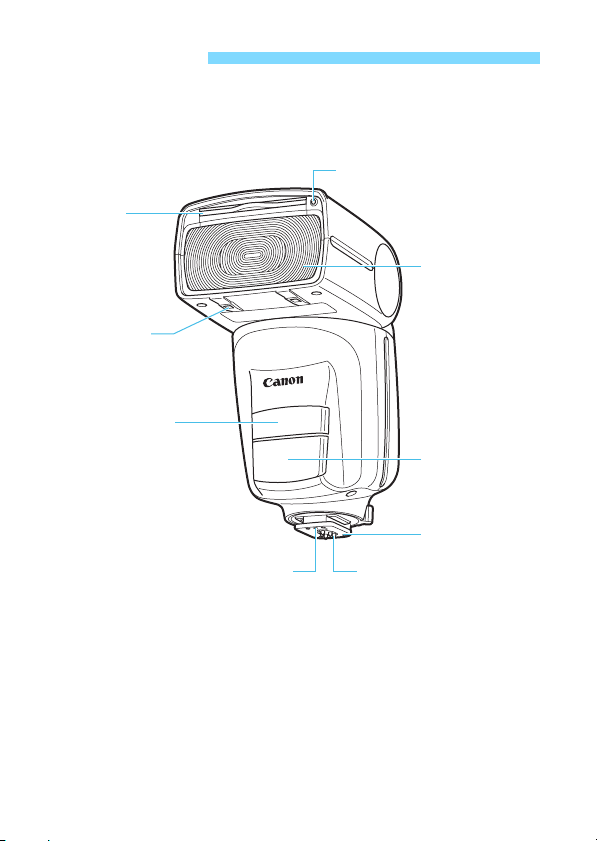
Nomenclature
Wide panel
(Retracted, p.35)
Bounce adapter
detector
Optical transmission
wireless sensor
Locking pin
AI.B distance
measurement sensor
Flash head
(Light-emitting unit)
AF-assist beam
emitter (p.27)
Mounting foot
(p.20)
Contacts
10
Page 11
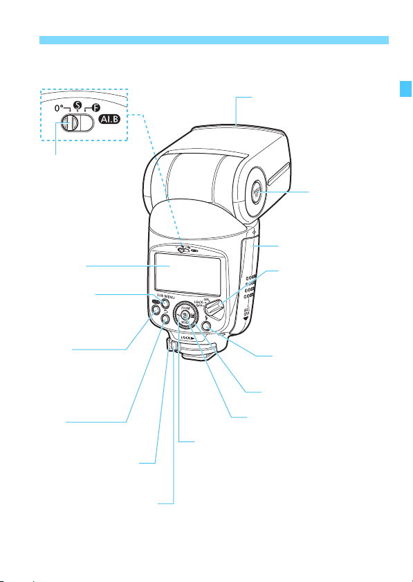
<X> Bounce mode
switch (p.42)
<0°> : Flash head
forward-facing
position
<Y> : AI.B semi-auto
<Z> : AI.B full-auto
LCD panel
<1>
Sub-menu button
(p.40, 75, 82)
Nomenclature
Bounce adapter attachment
(p.63)
<z>
Bounce angle
setting button
(p.45, 54, 57)
Battery compartment
cover (p.18)
Power switch (p.21)
<K>:Power on
<a>: Button/Dial lock
(Power on)
<J>:Power off
<X>
AI.B full-auto distance
measurement start
button/AI.B lamp
(p.43, 49/54, 59)
<0>
Back button
Mounting foot lock lever
(p.20)
Lock-release button (p.20)
<Q> Flash-ready lamp/
Test flash button (p.21, 77)
<9> Select dial
<8> Select/Set button
<S> Cross keys
<H> Zoom button (p.34)
<E> Flash mode button (p.24, 36)
<I> Wireless setting button (p.74, 79)
<O> Flash exposure compensation/
Flash output setting button (p.30/36)
11
Page 12
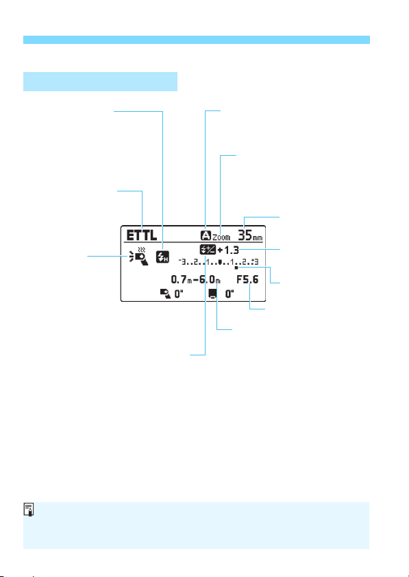
Nomenclature
LCD Panel
E-TTL II/E-TTL Autoflash
2:
First-curtain sync
(Normal flash photography,
p.68)
r : Second-curtain sync
(p.33, 68)
c : High-speed sync
(p.32, 68)
a :
E-TTL II/E-TTL
autoflash
(p.24)
G : Charge indicator (p.21)
L : Automatic setting
d : Manual setting (p.34)
e : Zoom display (p.34)
N : Wide panel + bounce
warning
O: Outside of flash
coverage warning
Flash coverage
(Focal length, p.34)
v : Aperture (p.36)
R : Meters
@ : Feet
Flash exposure
compensation amount
(p.30)
Flash exposure level
(p.30)
j : Standard
k : Guide number
priority (p.87)
l : Even coverage
(p.87)
t : Temperature increase
(Flash firing restriction, p.96)
f: Flash exposure compensation
(p.30, 68)
Effective flash metering range/
Shooting distance (p.24/36)
The displays shown are examples. The display will show only the
settings currently applied.
When a button or dial is operated, the LCD panel illuminates (p.22).
12
Page 13
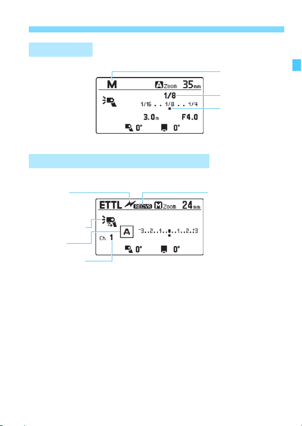
Nomenclature
Manual Flash
(p.36)
Optical Transmission Wireless Shooting
Receiver unit
: : Optical
transmission
wireless
shooting (p.74)
h : Receiver icon
Firing group
(p.78)
* : Transmission
channel
(p.74)
q : Manual flash
Manual flash output
Manual flash level
(p.71)
x : Receiver
setting (p.74)
( :
Individual receiver (p.79)
13
Page 14
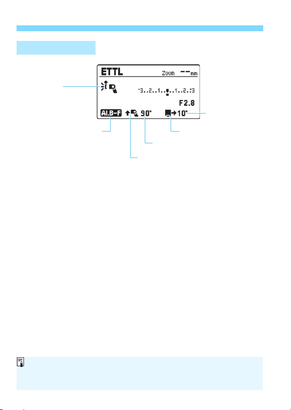
Nomenclature
Bounce Shooting
m : Bounce
(p.49, 56, 61)
H : Bounce adapter
attached (p.63)
W : AI.B full-auto (p.48)
V : AI.B semi-auto (p.56)
(p.41)
Horizontal direction
Flash head upward angle
Upward direction
Flash head
rotation angle
The rotation angle of the flash head is displayed in 5 increments.
If the camera’s orientation is horizontal during AI.B full-auto shooting, the
bounce angle in the upward direction is displayed up to 180°.
14
Page 15
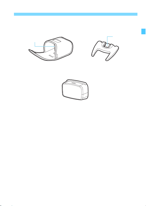
Accessories Provided
Nomenclature
Mini stand
pocket
Speedlite case
Bounce adapter
SBA-E4
(p.63)
Mini stand
(p.73)
Attachment
15
Page 16

16
Page 17
1
Getting Started and
Basic Operations
This chapter describes the preparations before starting
flash photography and the basic shooting operations.
Cautions for firing continuous flash
To avoid degrading and damaging the flash head due to
overheating, limit firing the flash continuously at full output
up to 30 times. After firing the flash continuously at full
output for 30 times, allow a rest time of at least 10 min.
If you fire the flash continuously at full output for the above
listed number of times, and then fire the flash again
repeatedly at short intervals, the safety function may
activate and restrict flash firing. With flash firing restriction
level 1, the firing interval is automatically set to approx. 8
sec. If this happens, allow a rest time of at least 40 min.
For details, see “Flash Firing Restriction due to Temperature
Increase” on page 96.
When you are not performing bounce flash photography, set the
<X> bounce mode switch to the <0°> position (p.11). For more
information on bounce flash photography, see Chapter 3 “Bounce
Flash Photography” (p.41).
17
Page 18
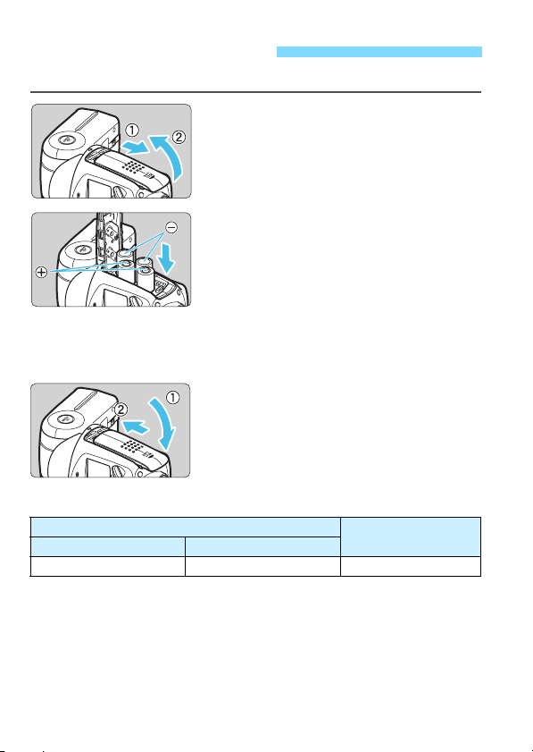
Installing the Batteries
Install four AA/R6 batteries for power supply.
Open the cover.
1
Slide the battery compartment cover
down, then open the battery
compartment cover.
Install the batteries.
2
Make sure the “+” and “-” electrical
contacts are correctly oriented as
shown in the battery compartment.
The grooves on the side surfaces
inside the battery compartment
indicate “-”. This is convenient when
replacing the batteries in a dark
place.
Close the cover.
3
Close the battery compartment cover,
then slide it up by following the
procedure of step 1 in reverse.
Firing Interval and Number of Flashes
Firing Interval
Quick Flash Normal Flash
Approx. 0.1 to 3.9 seconds
Based on new AA/LR6 alkaline batteries and Canon’s testing standards.
The Quick flash function enables flash photography before the flash is fully
charged (p.21).
Approx. 0.1 to 5.5 seconds
Number of Flashes
Approx. 115 to 800 times
18
Page 19
Installing the Batteries
CAUTION
Do not use “AA/R6 lithium batteries”.
Note that certain AA/R6 lithium batteries may become extremely hot in rare
cases during use. Due to safety reasons, do not use “AA/R6 lithium
batteries”.
When performing continuous flash, do not touch the flash head,
batteries, or the area near the battery compartment.
When continuous flash or modeling flash is repeatedly fired at short
intervals, do not touch the flash head, batteries, or the area near the battery
compartment. The flash head, batteries, and area near the battery
compartment may become hot, resulting in the risk of burn.
Do not use the Speedlite while touching the same part for a long
period of time.
Even if the product does not feel too hot, prolonged contact with the same
body part may cause skin redness or blistering due to low-temperature
contact burns. Using a tripod is recommended in very hot places or for
people with circulation problems or very sensitive skin.
Using AA/R6 batteries other than the alkaline type may cause contact failure
due to the irregular shape of the battery contacts.
When <!> is displayed or the LCD panel display turns off during
recharging, replace the batteries with new ones.
Use a new set of four batteries of the same brand. When replacing the
batteries, replace all four at one time.
AA/HR6 Ni-MH batteries can also be used.
19
Page 20
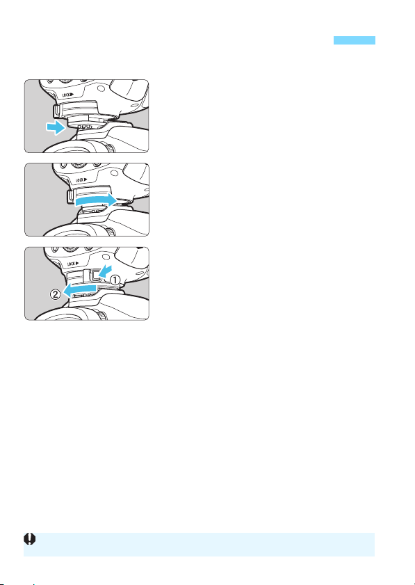
Attaching and Detaching the Speedlite to and from the Camera
Attach the Speedlite.
1
Slip the Speedlite’s mounting foot all
the way into the camera’s hot shoe.
Secure the Speedlite.
2
Slide the mounting foot lock lever to
the right.
X When the lock lever clicks in place, it
is locked.
Detach the Speedlite.
3
While pressing the lock-release
button, slide the lock lever to the left
and detach the Speedlite from the
camera.
Be sure to turn off the Speedlite before attaching or detaching it.
20
Page 21
Turning on the Power
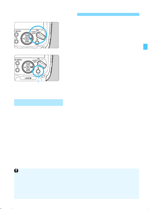
Set the power switch to <K>.
1
X The flash recharge starts.
X During recharging, <G> is
displayed on the LCD panel. When
flash recharge is complete, this
indicator disappears.
Check that the flash is ready.
2
The status of the flash-ready lamp
changes from off to green (Quick
flash ready) to red (fully charged).
You can press the test flash button
Flash-ready lamp
(Test flash button)
Quick Flash Function
The Quick flash function enables flash photography when the flashready lamp is lit green (before the flash is fully charged). Quick flash is
available regardless of the camera’s drive mode setting. Although the
flash output will be approx. 1/2 to 1/6 of the full output, it is useful for
shooting with a shorter firing interval.
During manual flash photography, this function is available when the
flash output is set to 1/4 to 1/128. Note that you cannot use Quick flash
with the receiver unit during optical transmission wireless shooting.
(flash-ready lamp) to fire a test flash.
When the power is turned on, the flash head may automatically operate
(rotate).
When Quick flash is fired during continuous shooting, underexposure
may occur since the flash output decreases.
When the 3/1/o/7/2 timer of the camera is operating, a test
flash cannot be performed.
21
Page 22

Turning on the Power
Auto Power Off Function
To save battery power, the power will turn off automatically after approx.
90 sec. of idle use. To turn on the Speedlite again, press the camera’s
shutter button halfway or press the test flash button (flash-ready lamp).
When set as the receiver unit for optical transmission wireless flash
shooting (p.72), the time until auto power off takes effect is approx. 60
min.
Lock Function
By setting the power switch to <a>, you can disable the flash’s
button and dial operations (except the <X> switch operation). It is
useful when you want to prevent the flash function settings from being
accidentally changed after you set them.
If you operate a button or dial, <k> is displayed on the LCD panel.
LCD Panel Illumination
When a button or dial is operated, the LCD panel illuminates for approx.
12 sec. (p).
During normal flash photography, the LCD panel illuminates in green.
When set as a receiver unit during optical transmission wireless
shooting, the LCD panel illuminates in orange.
22
Page 23

Turning on the Power
The flash settings will remain in effect even after the power is turned off.
To retain the settings when replacing the batteries, replace the batteries
after turning off the power switch.
You can fire a test flash while the power switch is set to the <a>
position. Also, when a button or dial is operated, the LCD panel
illuminates.
Auto power off can be disabled (C.Fn-01, p.85).
When set as a receiver unit, you can change the time until the receiver
unit’s auto power off takes effect (C.Fn-10, p.86).
You can change the setting of the LCD panel illumination (C.Fn-22, p.87).
You can change the color of the LCD panel illumination (P.Fn-02/03,
p.88).
You can disable Quick flash (P.Fn-05, p.89).
23
Page 24
a:
When you set the camera’s shooting mode to <d> (Program AE) or a
fully automatic mode, you can shoot in E-TTL II/E-TTL fully automatic
flash mode.
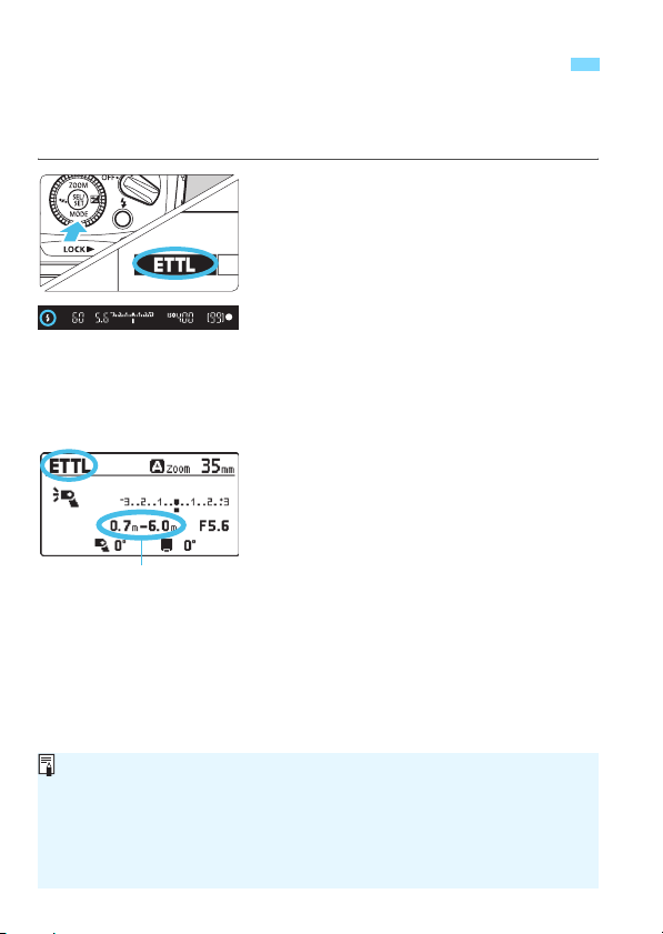
Effective flash metering range
Fully Automatic Flash Photography
Set the flash mode to <a>.
1
Press the <E> button of the
<S> cross keys.
Turn <9> to select <Q>, then
press <8>.
Focus on the subject.
2
Press the shutter button halfway to
focus.
X The shutter speed and aperture are
displayed in the viewfinder.
Check that <Q> is lit in the viewfinder.
Take the picture.
3
Check that the subject is in the
effective flash metering range.
When you press the shutter button
completely, the flash will fire and the
picture will be taken.
If the subject is dark (underexposed) when you check the shot image,
move closer to the subject and shoot again. You can also increase the
ISO speed when using a digital camera.
“Fully automatic” refers to <A>, <1>, and <C> shooting modes.
Even when attached to a camera that supports the E-TTL II autoflash
system, <a> is displayed on the LCD panel.
24
Page 25

E-TTL
II/E-TTL Autoflash by Shooting Mode
Simply by setting the camera’s shooting mode to <s> (shutter-priority
AE), <f> (aperture-priority AE), or <a> (manual exposure), you can
execute E-TTL II/E-TTL autoflash suitable for each shooting mode.
Select this mode when you want to set the shutter speed manually.
The camera will then automatically set the aperture matching the shutter
speed to obtain the standard exposure based on the metering of the camera.
s
If the aperture value blinks, it means that the background exposure will
be underexposed or overexposed. Adjust the shutter speed until the
aperture value stops blinking.
Select this mode when you want to set the aperture manually.
The camera will then automatically set the shutter speed, matching the
aperture to obtain the standard exposure based on the metering of the camera.
For low-light scenes, a slow sync speed will be used to obtain the standard
exposure for both the main subject and background. The standard exposure for
the main subject is obtained with the flash light, while the standard exposure for
f
the background is obtained with a long exposure using a slow shutter speed.
Since a slow shutter speed will be used for low-light scenes, using a
tripod is recommended.
If the shutter speed blinks, it means that the background exposure will
be underexposed or overexposed. Adjust the aperture until the shutter
speed stops blinking.
Select this mode if you want to set both the shutter speed and aperture
manually.
Standard exposure of the main subject is obtained with the flash light. The
a
exposure of the background changes according to the shutter speed and
aperture combination you set.
If you use the <Z> or <Y> shooting mode, the result will be the same as
using the <d> (Program AE) mode.
Flash Sync Speeds and Apertures by Shooting Mode
Shutter Speed Aperture
d Automatically set (1/X sec. to 1/60 sec.) Automatically set
s Manually set (1/X sec. to 30 sec.) Automatically set
f Automatically set (1/X sec. to 30 sec.) Manually set
a Manually set (1/X sec. to 30 sec., Bulb) Manually set
1/X sec. is the camera’s maximum flash sync speed.
25
Page 26

E-TTL II/E-TTL Autoflash by Shooting Mode
Auto Zoom Adjustment to Image Sensor Size
EOS DIGITAL cameras have three sizes of image sensors, and the
effective shooting angle of view of the attached lens varies depending
on the size of image sensor. 470EX-AI automatically recognizes the
image sensor size of the EOS DIGITAL camera and automatically sets
the flash coverage that is ideal for the effective shooting angle of view of
a lens for the focal length range of 24-105mm.
Color Temperature Information Transmission
This function adjusts the white balance depending on the color
temperature of the flash light by transmitting the color temperature
information to the EOS DIGITAL camera when the flash fires. When you
set the camera’s white balance to <A>, <Aw>, or <Q>, the
function is enabled automatically.
Refer to the specifications in your camera’s Instruction Manual to find
out if it is compatible with this function.
Bounce Function
See Chapter 3, “Bounce Flash Photography” (p.41-64).
When the <X> bounce mode switch is set to the <0°> position and the
flash head is facing a direction other than straight forward, the <X> lamp
blinks. Pressing the shutter button halfway automatically returns the position
of the flash head to the forward-facing position. (The <X> lamp turns off.)
26
Page 27

E-TTL II/E-TTL Autoflash by Shooting Mode
AF-Assist Beam
When it is difficult to autofocus on the
subject in low-light or when contrast is
low during viewfinder shooting, the
infrared AF-assist beam built into the
flash is automatically emitted to help
autofocus.
The AF-assist beam supports most of the EOS cameras’ AF points. The
AF-assist beam covers the angle of view of 28 mm or longer lens focal
length, and its effective range (at 28 mm focal length) is approx. 0.7 - 10
m/2.3 - 32.8 ft. at the center in the viewfinder and approx. 1 - 5 m/3.3 -
16.4 ft. at the periphery (AF points other than the center AF point).
If a peripheral AF point is selected, or a wide-angle or telephoto lens is
used, achieving focus may be difficult with an EOS-dedicated, external
Speedlite’s AF-assist beam. In such a case, use the center AF point or an
AF point close to the center.
During Live View shooting, the AF-assist beam is emitted even when the
AF method is set to [Quick mode].
AF-assist beam firing can be disabled (C.Fn-08, p.86).
The AF-assist beam type that uses intermittent flashes (a series of small
flashes) can be emitted (P.Fn-04, p.89).
27
Page 28

28
Page 29

2
Advanced Flash
Photography
This chapter describes advanced shooting operations
utilizing the flash functions.
When the camera’s shooting mode is set to a fully automatic
mode or a Basic Zone mode, the operations in this chapter
are not available. Set the camera’s shooting mode to <d/s/
f/a/bulb(B)> (Creative Zone mode).
When you are not performing bounce flash photography, set
the <X> bounce mode switch to the <0°> position (p.11).
For more information on bounce flash photography, see
Chapter 3 “Bounce Flash Photography” (p.41).
29
Page 30
f Flash Exposure Compensation
With a similar procedure as exposure compensation, you can adjust the
flash output. The flash exposure compensation amount can be set up to
±3 stops in 1/3-stop increments.
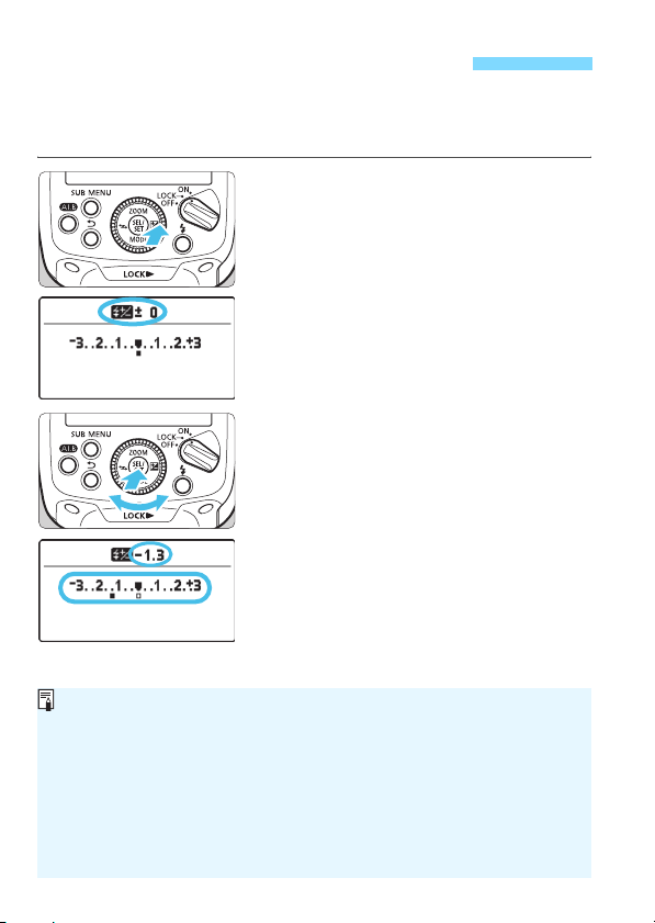
Press the <O> button.
1
Press the <O> button of the <S>
cross keys.
You can also select the flash
exposure compensation by pressing
<8> and turning <9>.
Set the flash exposure
2
compensation amount.
Turn <9> to set the flash exposure
compensation amount, then press
<8>.
X The flash exposure compensation
amount is set.
“0.3” indicates 1/3 stop and “0.7”
indicates 2/3 stops.
To cancel flash exposure
compensation, return the
compensation amount to ±0.
Generally, set an increased exposure compensation for bright subjects
and set a decreased exposure compensation for dark subjects.
If the camera’s exposure compensation is set in 1/2-stop increments, flash
exposure compensation will be up to ±3 stops in 1/2-stop increments.
When the flash exposure compensation is set on both the flash and the
camera, priority is given to the flash setting.
Without pressing the <O> button of the <S> cross keys, you can
directly turn <9> and set the amount of flash exposure compensation
(C.Fn-13, p.86).
30
Page 31

7: FE Lock
The FE (Flash Exposure) lock locks the correct flash exposure setting
for any part of the subject.
With <a> displayed on the LCD panel, press the camera’s
<
B> button. For cameras without a <B> button, press the
<A> (AE lock) or <7> button.
Focus on the subject.
1
Press the <B> button (8).
2
With the subject at the center of the
viewfinder, press the camera’s
<B> button.
X The Speedlite will fire a preflash and
the required flash output for the
subject is retained in memory.
X “FEL” will be displayed in the
viewfinder for approx. 0.5 sec.
Each time you press the <B>
button, a preflash will be fired and the
new flash output required at that time
is retained in memory.
If a correct exposure cannot be obtained when FE lock is performed,
<Q> blinks in the viewfinder. Move closer to the subject or open the
aperture, and perform FE lock again. You can also set a higher ISO
speed and perform FE lock again when using a digital camera.
If the target subject is too small in the viewfinder, FE lock may not be
effective.
31
Page 32

c High-speed Sync
With high-speed sync, you can shoot with a flash even at shutter
speeds that exceed the maximum flash sync shutter speed. This is
effective when you want to shoot in the aperture-priority AE <f>
mode (open aperture) with background blur in locations such as
outdoors in daylight.
Press <8>.
1
Select the item in the illustration.
2
Turn <9> to select the item in the
illustration, then press <8>.
Select <c>.
3
Turn <9> to select <c>, then press
<8>.
Check that <F> is lit in the
viewfinder, then take the picture.
With high-speed sync, the faster the shutter speed, the lower the guide
number becomes. You can check the effective flash metering range on the
LCD panel.
When the shutter speed is less than or equal to the maximum flash sync
shutter speed, <F> is not displayed in the viewfinder.
To return flash firing to normal, select <2> (first-curtain sync) in step 3.
(<2> will not be displayed on the LCD panel after you perform this
setting.)
32
Page 33

r Second-curtain Sync
Shooting with a slow shutter speed and second-curtain sync captures
the trail of the light sources of a moving subject, such as car lights, in a
natural way. The flash fires right before the exposure finishes (shutter
closes).
Press <8>.
1
Select the item in the illustration.
2
Turn <9> to select the item in the
illustration, then press <8>.
Select <r>.
3
Turn <9> to select <r>, then
press <8>.
The second-curtain sync works well when the camera’s shooting mode is
set to <bulb(B)> (bulb shooting).
When the flash mode is set to <a>, the flash fires twice. The first
flash is a preflash to determine the flash output. It is not a malfunction.
Second-curtain sync is not available during wireless flash photography.
To return flash firing to normal, select <2> (first-curtain sync) in step 3.
(<2> will not be displayed on the LCD panel after you perform this
setting.)
33
Page 34

H:Setting the Flash Coverage
Flash coverage (the range covered by the flash light) can be set
automatically or manually. With <L> (automatic setting), the flash
coverage is adjusted automatically according to the focal length
(shooting angle of view) of the lens in use and the image sensor size
(p.26). With <d> (manual setting), you can manually set flash coverage
in the range of 24 mm to 105 mm.
Press the <H> button.
1
Press the <H> button of the
<S> cross keys.
Set the flash coverage.
2
To set the flash coverage
automatically, set <X>. To set the
flash coverage manually, select a
number (indicating the focal length in
mm).
Turn <9> to select the flash
coverage, then press <8>.
When you set the flash coverage manually, set the same or a wider
coverage than the angle of view for shooting to avoid darkening the
periphery of the picture.
When a lens with a focal length less than 24 mm is attached, the
<O> warning is displayed on the LCD panel. When using a camera
with the image sensor size smaller than full-frame, the <O>
warning is displayed when the actual shooting angle of view is wider than
the angle of view of a 24 mm lens.
34
Page 35

H:Setting the Flash Coverage
Wide Panel
When you use the flash’s built-in wide panel together with the flash, you
can perform flash photography covering the angle of view of an ultrawide angle lens with a focal length as wide as 14 mm.
Pull out the wide panel.
Pull out the protruding area located in
the center of the wide panel.
Fold down the wide panel.
Since underexposure may occur, the <N> warning is displayed on
the LCD panel when using the wide panel with bounce flash.
Do not pull out the wide panel with excessive force. Doing so may detach
the wide panel from the Speedlite.
Angle of view of EF15mm f/2.8 Fisheye or EF8-15mm f/4L Fisheye USM
is not supported.
When the wide panel is pulled out, AI.B full-auto shooting (p.48) is not
possible.
The flash coverage is set automatically when using the wide panel. You
cannot change the setting.
You can perform flash photography with the wide panel even when the
camera’s shooting mode is set to a fully automatic mode or a Basic Zone
mode.
35
Page 36

a: Manual Flash
You can set the flash output from 1/1 full output to 1/128 power in 1/3step increments.
Use a flash meter (commercially-available) to determine the required
flash output to obtain a correct flash exposure. Setting the camera’s
shooting mode to <f> or <a> is recommended.
Set the flash mode to <a>.
1
Press the <E> button of the
<S> cross keys.
Turn <9> to select <R>, then
press <8>.
Set the flash output.
2
Press the <O> button of the <S>
cross keys.
Turn <9> to set the flash output,
then press <8>.
When you press the camera’s shutter
button halfway, an approximate
indication of the effective shooting
distance and the aperture value are
displayed.
Shooting distance
Aperture
For guide number details with manual flash, see page 109.
Without pressing the <O> button of the <S> cross keys, you can
directly turn <9> and set the flash output (C.Fn-13, p.86).
36
Page 37

a: Manual Flash
Metered Manual Flash Exposure
When using an EOS-1D series camera, the flash exposure level can be
manually set before shooting. This is effective when you are close to the
subject. Use an 18% gray reflector (commercially available) and shoot
as follows.
1 Configure the camera and Speedlite settings.
Set the camera shooting mode to <a> or <f>.
Set the Speedlite’s flash mode to <a>.
2 Focus on the subject.
Focus manually.
3 Set up an 18% gray reflector.
Place the gray reflector at the subject’s position.
Aim the camera so that the entire spot metering circle within the
viewfinder center is over the gray reflector.
4 Press the <B>, <P>, or <7> button (8).
X The Speedlite will fire a preflash and the required flash output for
the correct flash exposure is retained in memory.
X On the right side of the viewfinder, the exposure level indicator
will show the flash exposure level against the standard exposure.
5 Set the flash exposure level.
Adjust the Speedlite’s manual flash output and the
aperture so that the flash exposure level aligns with
the standard exposure index.
6 Take the picture.
Remove the gray reflector and take the picture.
Metered manual flash exposure is available only with EOS-1D series
cameras.
37
Page 38

Modeling Flash
When the camera’s depth-of-field preview button is pressed, the flash
fires continuously for approx. 1 sec. This feature is called “modeling
flash”. This is useful for checking shadows cast on the subject by the
flash light.
Press the depth-of-field preview
button on the camera.
X The flash fires continuously for
approx. 1 sec.
Modeling Flash in AI.B Full-Auto Mode
When an EOS DIGITAL camera released in or after the second half of
2017 (excluding some cameras, p.46) is used and the <X> switch is
set to <Z> full auto, the camera’s depth-of-field preview button
functions as an AI.B full-auto distance measurement start button.
With this setting, you can fire a modeling flash using the test flash
button on the flash in AI.B full-auto shooting if the Custom function
C.Fn-02 is set to 1 or 2 (p.85).
38
Page 39

Modeling Flash
To avoid degrading and damaging the flash head due to overheating,
limit firing the modeling flash up to 20 times. After firing modeling flash
for 20 times, allow a rest time of at least 10 min.
If you fire the modeling flash for the above listed number of times, and
then fire the flash again repeatedly at short intervals, the safety function
may activate and restrict flash firing. With flash firing restriction level 1,
the firing interval is automatically set to approx. 8 sec. If this happens,
allow a rest time of at least 40 min.
During Live View shooting, firing modeling flash (by operating the
camera) is not possible.
Modeling flash (by operating the camera) is disabled when using the
flash with EOS M6, EOS M5, EOS M3, EOS M2, EOS M, EOS Elan II/
Elan II E/50/50E, EOS REBEL 2000/300, EOS REBEL G/500N, EOS
REBEL K2/3000V, EOS REBEL XS N/REBEL G II/3000N/66, EOS IX, or
EOS IX Lite/IX7. Set C.Fn-02 to 1 or 2 (p.85), and then fire modeling
flash using the test flash button. (When using the EOS M series cameras
listed above, the test flash button functions when the camera’s metering
timer is not active.)
You can use the test flash button to fire the modeling flash (C.Fn-02, p.85).
39
Page 40

Clearing Speedlite Settings
You can revert the settings of the Speedlite shooting functions and
wireless shooting settings to their defaults.
Display the Clear Settings screen.
1
Press the <1> button.
Turn <9> to select <B>, then
press <8>.
X A confirmation screen is displayed.
Clear the settings.
2
Turn <9> to select <;>, then
press <8>.
X The Speedlite settings are cleared,
and normal flash photography with
<a> flash mode will be set.
Even when the settings have been cleared, the transmission channel for
optical transmission wireless receiver unit as well as the settings of the
Custom Functions (C.Fn) and Personal Functions (P.Fn) will not be cleared.
40
Page 41

3
Bounce Flash
Photography
This chapter describes functions related to the bounce
flash function, such as flash photography that uses the
AI.B full-auto function, AI.B semi-auto function, manual
bounce, and bounce adapter.
Cautions for the AI Bounce Flash Function
During AI.B full-auto and AI.B semi-auto shooting, the flash
head moves and fires automatically. The flash head may fire in
an unintended direction. Before performing AI bounce flash
photography, be sure to warn those around you. Additionally,
when you want to perform AI bounce flash photography, follow
the precautions below.
• Make sure your eyes are not close to the flash head.
• The flash head may come in contact with objects. Make sure
your face, head, and the like are not close to the flash head.
• The flash head moves. Be sure to hold the camera securely.
• Do not allow your hair or the like to get entangled with the
flash head.
• Be careful of the orientation of the flash head in low angle
shooting.
41
Page 42

X
AI Bounce Flash
By pointing the flash head toward a ceiling, you can utilize the reflection
of the flash light off the surface for flash photography, making it possible
to soften the shadows of the subject for a more natural-looking shot.
This shooting technique is called “Bounce flash photography”.
Bounce flash photography allows you to get a more natural-looking shot
compared to techniques that light the subject directly with the flash light.
Shooting with the appropriate exposure, however, may require some
knowledge and experience.
This Speedlite comes with an “AI bounce (AI.B) flash function” that
enables you to perform bounce flash photography automatically. There
are two AI bounce flash modes: “AI.B full-auto mode” and “AI.B semiauto mode”. With AI.B full-auto function, the camera performs the
bounce flash photography automatically, requiring only simple
operations.
Bounce Mode
Slide the <X> bounce mode switch to switch the AI bounce flash
mode.
0° : Set when performing normal flash
photography (not bounce flash
photography).
Y: Allows you to perform “AI.B semi-
auto shooting” (p.45, 56).
Z: Allows you to perform “AI.B full-
auto shooting” (p.43, 46, 48).
When the bounce mode is switched, the flash head automatically moves
to the forward-facing position.
When the flash head is moving, do not touch it.
When you are to perform manual bounce flash photography, set P.Fn-09
to 1 (p.92) and set the switch to the <0°> position.
42
Page 43

X AI Bounce Flash
AI.B Full-Auto
W
This mode is geared for beginners. In this mode, the camera performs
the bounce flash photography automatically, requiring only simple
operations. When the <X> AI.B full-auto distance measurement start
button is pressed, the flash fires briefly (preflash) to measure the
distance to the subject and the distance to the ceiling for bouncing the
flash light. Based on the result of distance measurement, the orientation
(bounce angle) of the flash head is automatically set.
For AI.B full-auto shooting, see pages 46-55.
perform the following operations automatically.
1. Fires the flash
toward the subject.
When using an EOS DIGITAL camera released in or after the second half of
2017 (p.46), you can perform the same distance measurement operation as
described above using the camera’s depth-of-field preview button.
Press the <X> button to
2. Fires the flash
toward the ceiling.
3. Sets the bounce
angle automatically.
43
Page 44

X AI Bounce Flash
Note if you change the orientation (position) of the camera, doubleclicking the camera’s shutter button (pressing the shutter button halfway
two times in a row within a short period) makes the flash head move
automatically, resetting the bounce angle to substantially the same
angle as before you changed the orientaion of the camera.
x2
Change the orientation
(position) from state 3
on previous page.
Depending on the camera used, AI.B full-auto shooting may not be
available. Additionally, even if the camera supports AI.B full-auto shooting,
some operations may be limited. See page 46 for details.
Resets the bounce
angle to substantially
the same as that in 3.
44
Page 45

X AI Bounce Flash
AI.B Semi-Auto
V
This mode is geared for intermediate and advanced photographers.
You can store (register) the bounce angle in the Speedlite by pressing
the <z> button after setting the orientation (bounce angle) of the
Speedlite’s flash head as desired.
For AI.B semi-auto shooting, see pages 56-59.
1. Set the bounce angle as desired. 2. Press the <z> button.
Note if you change the orientation (position) of the camera, doubleclicking the camera’s shutter button (pressing the shutter button halfway
two times in a row within a short period) makes the flash head move
automatically, resetting the bounce angle to substantially the same
angle as before you changed the orientaion of the camera.
x2
Change the orientation
(position) from state 2.
Resets the bounce
angle to substantially
the same as that in 2.
45
Page 46

W AI.B Full-Auto
Depending on the camera used, AI.B (AI bounce flash) full-auto mode
compatibility and some of the operations to start AI.B full-auto shooting
vary (EOS cameras released up to the first half of 2014 do not
support AI.B full-auto shooting).
During AI.B full-auto shooting, the flash fires briefly (preflash) before the
image is shot to measure the distance to the subject and the distance to
the ceiling for bouncing the flash light. This operation automatically sets
an appropriate bounce angle for the subject.
You can perform this operation using one of the following two methods.
The operating procedure differs according to the camera used.
1. Use the Speedlite’s <X> AI.B full-auto distance measurement
start button.
2. Use the camera’s depth-of-field preview button.
AI.B Full-Auto Compatible Cameras and Operation Restrictions
EOS DIGITAL cameras released in and after the second half
of 2017
You can start distance measurement for AI.B full-auto shooting using
either operation 1 or 2 described above.
* While EOS REBEL T7/2000D/1500D and EOS REBEL T100/3000D/4000D,
were released in or after the second half of 2017, the cameras provide the
same compatibility as “EOS cameras released up to the first half of 2014” on
the next page. AI.B full-auto shooting cannot be performed.
For information on the latest cameras supporting the AI.B full-auto
function, refer to the Canon Web site.
When using an EOS DIGITAL camera released in or after the second
half of 2017 not equipped with the depth-of-field preview button, you can
assign the depth-of-field preview function to a button with the camera’s
customization features and start distance measurement for AI.B full-auto
shooting (perform the same operation as 2) by pressing the button
(except for the certain buttons).
46
Page 47

W AI.B Full-Auto
EOS DIGITAL cameras released from the second half of
2014 up to the first half of 2017
When using EOS-1D X Mark II, EOS 5DS/5DS R, EOS 5D Mark IV,
EOS 7D Mark II, EOS 80D, EOS 77D, EOS REBEL T6S/760D, EOS
REBEL T7i/800D, or EOS REBEL T6i/750D, you can perform fullauto bounce flash photography by performing operation 1. You
cannot start distance measurement operation of the AI.B fullauto shooting by operation 2.
* While EOS REBEL T6/1300D, EOS M6, EOS M5 and EOS M3 were
released in or after the second half of 2014, the cameras provide the same
compatibility as “EOS cameras released up to the first half of 2014”. AI.B fullauto shooting cannot be performed.
EOS DIGITAL cameras released up to the first half of 2014
AI.B full-auto shooting cannot be performed.
Perform AI.B semi-
auto shooting (p.56) or manual bounce flash photography (p.61).
Do not press the <X> button and then fully press the shutter button
(take a shot) during the AI.B full-auto distance measurement operation.
The Speedlite may be fired at full output, and accurate distance
measurement operation may not be performed.
When the camera’s shooting mode is set to a mode in which the flash is
not fired, or when [Flash firing] in [External Speedlite control] or
[Flash control] mode (p.66) is set to [Disabled], distance measurement
is not performed during AI.B full-auto shooting even if the camera’s
depth-of-field preview button is pressed when using an EOS DIGITAL
camera released in or after the second half of 2017.
When using an EOS DIGITAL camera released in or after the second
half of 2017 and after pressing the depth-of-field button, a shot cannot be
taken during distance measurement operation even when you press the
shutter button completely (release lock). Perform shooting after the
distance measurement operation is complete.
47
Page 48

W AI.B Full-Auto Shooting
Before performing AI.B (AI bounce flash) full-auto shooting, check if the
camera used supports full-auto bounce flash photography (p.46).
For an overview of AI.B full-auto shooting, see page 43. Additionally,
before performing AI.B full-auto shooting, review the “Safety
Precautions” (p.8), “General Cautions for AI.B Full-Auto Shooting and
AI.B Semi-Auto Shooting” (p.60), and the like.
Guidelines for Shooting Conditions in AI.B Full-Auto Mode
When performing AI.B full-auto shooting, perform bounce flash
photography using the figure below as reference. Additionally, with the
subject positioned in the center of the screen, press the <X> button
(to start distance measurement operation).
Distance to ceiling
Approx. 1 - 3 m /
3.3 - 9.8 ft.
Shooting distance
Approx. 1 - 5 m / 3.3 - 16.4 ft.
Under conditions such as when the subject is far away, the ceiling is far
away, the ceiling is a dark color, the ceiling is stepped or uneven, the
camera’s ISO speed setting is low, or a large aperture value is set,
underexposure (insufficient exposure) is prone to occur.
When the distance to the ceiling is approx. 7 m / 23 ft. or greater
(estimate), or when the shooting angle exceeds approx. 60° upward or
approx. 60° downward, the flash head automatically moves to the
forward-facing position and normal flash shooting is performed without a
bounce flash.
48
Page 49

AI.B Full-Auto Shooting
1
2
W AI.B Full-Auto Shooting
Set the <X> switch to the <Z>
position
With the Speedlite attached to the
Set the <X> bounce mode switch
X When the flash head is not in the
(p.42).
camera, check that both the camera
and the Speedlite are turned on.
to the <Z> position.
forward-facing position, the flash
head moves and is automatically set
to face forward.
Press the <X> button.
Check that the <&> flash-ready lamp
is lit.
With the subject positioned in the
screen center, press the <X>
button.
The distance to the subject and the
distance to the ceiling for bouncing
the flash light are measured (distance
measurement operation). Note that
the flash fires briefly twice (preflash)
during the operation.
You can also start the distance
measurement using the depth-of-field
preview button, depending on the
camera used (p.
X When the distance measurement
completes, the bounce angle is
automatically set.
X The Speedlite icon on the LCD panel
changes to <m>.
46).
49
Page 50

W AI.B Full-Auto Shooting
Take the picture.
3
Focus on the subject and take the
picture in the same way as with
normal flash photography.
X The flash fires at the automatically set
bounce angle and the picture is
taken.
Play back the image, then check the
result.
When the camera is equipped with a flash mode that disables flash firing,
set the mode to one that does not disable flash firing.
During AI.B full-auto shooting, the flash coverage is automatically set.
You cannot manually change the setting.
Even if [Flash firing] in the camera’s menu function [External Speedlite
control] or [Flash control] is set to [Disabled], when you press the
<X> button, the preflash will be fired to measure the distance.
When the distance to the subject is short, the bounce angle may be set
to 90° or greater. This is a normal operation. By relaxing the angle in
which the flash light hits the subject (making the incident angle
shallower), you can suppress the shadow on the subject (example: the
shadow beneath the face when taking a picture of a person).
During bounce photography, the flash coverage is set to 50 mm and <-->
is displayed.
With the position of the flash head moved (inadvertently) after the
distance measurement operation by pressing the <X> button or the
like (with the AI.B lamp blinking), if you press the shutter button halfway
or press any other button on the camera, automatic correction may be
performed to set the bounce angle to the position at the time when it was
automatically set by the distance measurement operation. Note that
when you press the shutter button completely with the AI.B lamp
blinking, the Speedlite will not fire until the flash head is moved to the
appropriate position.
50
Page 51

W AI.B Full-Auto Shooting
What To Do When You Change the Camera Orientation
(Position)
Note that if you change the orientation
(position) of the camera after pressing
x2
the <X> button, etc. and executing
AI.B full-auto distance measurement,
double-clicking the camera’s shutter
button (pressing the shutter button
halfway two times in a row within a short
period) activates the flash head to move
automatically, resetting (automatically
correcting) the bounce angle to
substantially the same angle as before
you changed the orientation (position).
This function is convenient when the
camera’s horizontal or vertical orientation
has changed.
When a picture is taken during automatic correction of the bounce angle,
the flash does not fire.
When shooting conditions (subject, distance from subject, distance to
ceiling, etc.) change, press the <X> button once again to repeat the
distance measurement (p.49).
You can select the method to perform the automatic bounce angle
correction (P.Fn-08, p.91).
51
Page 52

W AI.B Full-Auto Shooting
FAQ
When the shooting distance to the subject changes
Press the <X> button or the like (p.49) and re-measure the
shooting distance to the subject.
When a warning appears on the Speedlite LCD panel
Warni ng Solution
AI.B[
RETRY
AI.B ERROR
CAMERA POWER
IS OFF
AI.B-F
WIDE PANEL
BOUNCE ADAPTER
WIDE PANEL +
BOUNCE ADAPTER
Attach the Speedlite to the camera, then press the
<X> button.
An obstacle has come into contact with the flash
head preventing the appropriate operation.
Remove the obstacle and perform the same
operation once again.
The same operation was performed three times,
but the appropriate operation could not be
completed. Turn the power off and on again,
temporarily set the <X> switch to the <0°>
position, or do the like.
The camera is not compatible with AI.B full-auto
mode. Perform AI.B semi-auto shooting (p.56) or
manual bounce flash photography (p.61).
The camera power is not turned on. Turn on the
camera power, then press the <X> button.
Flash coverage angle cannot be manually set
during AI.B full-auto shooting.
The wide panel cannot be used during AI.B
full-auto shooting. Retract the wide panel.
When the bounce adapter is used, the flash
coverage cannot be set manually.
With the wide panel pulled out, the bounce
adapter is attached. The flash coverage cannot be
set manually.
52
Page 53

W AI.B Full-Auto Shooting
The flash head does not move when the camera’s depth-of-field
preview button is pressed.
To check whether or not the camera’s depth-of-field preview button
can be used to start distance measurement in AI.B full-auto mode
(checking if the camera is compatible), see page 46.
The bounce angle is not automatically corrected even when the
orientation (position) of the camera is changed.
Double-clicking the camera’s shutter button (pressing the shutter
button halfway two times in a row within a short period) activates the
flash head to move automatically, resetting the bounce angle to
substantially the same angle as before you changed the orientation
(position) of the camera.
Pictures are underexposed (insufficiently exposed).
During bounce flash photography, less light reaches the subject and
thus underexposure (insufficient exposure) is prone to occur. Take
the action such as taking the picture as close to the subject as
possible, increasing the camera’s ISO speed, or opening the
aperture of the lens before shooting.
Further, when the ceiling or wall for bouncing the flash light on is too
far away, the ceiling is a dark color, or the ceiling is stepped or
uneven, shooting with the appropriate exposure may not be possible
since not enough light may reach the subject.
The color of the subject is not right.
If the surface for bouncing the flash light is not white, a color cast
may result in the picture or shooting with the appropriate exposure
may not be possible since the bounced flash light may not reach the
subject. Select a ceiling or wall that is close to a white color for
bouncing the flash light off for high reflectance.
If the battery is not installed in the camera, the warning on the Speedlite may
not be correctly displayed when the <X> button is pressed.
53
Page 54

W AI.B Full-Auto Shooting
AI.B Lamp
X
Depending on the state of the flash head
during AI.B full-auto shooting, the display
(lit/blinking) of the blue <X> lamp
changes.
Lamp Status
Off Before AI.B full-auto shooting is started
High-speed
blinking
Lit
Low-speed
blinking
: Bounce Angle Setting Button
z
AI.B full-auto distance measurement in progress or bounce
angle correction in progress
Distance measurement is complete (AI.B full-auto shooting
possible)
When bounce angle changed after distance measurement
operation is complete
Error in AI.B full-auto mode
When the bounce angle changed after registration (with
<z> set)
When the flash head is not in the forward-facing position
(before shooting in AI.B full-auto mode)
When the <z> button is pressed during AI.B full-auto shooting, the
bounce angle is stored (registered) in the Speedlite, and AI.B semi-auto
shooting can be performed. For AI.B semi-auto shooting, see pages 56-
59.
54
Page 55

W AI.B Full-Auto Shooting
General Cautions for AI.B full-auto Shooting
When the <X> is switched to another mode or when the power switch
is set to <J>, the bounce angle stored (registered) in the Speedlite is
cleared.
When using the FE lock or self-timer, double-click the shutter button, and
once the flash head is reset (automatic correction) to the stored
(registered) position, perform the FE lock operation or shooting.
When a picture is taken with the camera oriented downward or upward,
the appropriate bounce angle may not be automatically set. If this
happens, take the picture using the following technique.
• Perform AI.B semi-auto shooting (p.56)
•Set the <X> switch to the <0°> position so that the flash head is
facing forward (p.42).
• Manual bounce flash photography (p.61)
When the <X> button is pressed during movie shooting, although
AI.B full-auto distance measurement operation (preflash) is performed,
flash photography cannot be performed.
When you turn the flash head, turn it slowly. While it may make a sound
when you turn the flash head, it is not a malfunction. However, it may
result in a mechanical failure if you continuously turn the flash head fast.
During AI.B full-auto shooting, you can fire the flash at the desired bounce
angle as in manual bounce flash photography by pressing the <z>
button after determining the orientation (position) of the camera and
adjusting the flash head.
55
Page 56

V AI.B Semi-Auto Shooting
For an overview of AI.B (AI bounce flash) semi-auto mode, see page 45.
AI.B semi-auto shooting can be performed with all the EOS cameras.
Before performing AI.B semi-auto shooting, review the “Safety
Precautions” (p.8), “General Cautions for AI.B Full-Auto Shooting and
AI.B Semi-Auto Shooting” (p.60), and the like.
Guidelines for Shooting Conditions in AI.B Semi-Auto Mode
See “Guidelines for Shooting Conditions in AI.B Full-Auto Mode” on
page 48.
AI.B Semi-Auto Shooting
Set the <X> switch to the <Y>
1
position
With the Speedlite attached to the
Set the <X> bounce mode switch
X When the flash head is not in the
Set the bounce angle as desired.
2
Determine the orientation (position) of
Taking into consideration factors such
X The Speedlite icon on the LCD panel
(p.42).
camera, check that both the camera
and the Speedlite are turned on.
to the <Y> position.
forward-facing position, the flash
head moves and is automatically set
to the forward-facing position.
the camera when taking a picture,
and then perform steps 2 and 3.
as the distance to the subject and the
distance to the ceiling, manually
move the flash head and set the
bounce angle.
changes to <m>.
56
Page 57

x2
V AI.B Semi-Auto Shooting
Press the <z> button.
3
After you determine the bounce angle
in step 2, press the <z> button to
store (register) the bounce angle in
the Speedlite.
To re-register the bounce angle,
perform steps 2 and 3 again.
Take the picture.
4
When the orientation (position) of the
camera changes after the bounce
angle is stored (registered) in the
Speedlite in step 3, double-click the
camera’s shutter button (press the
shutter button halfway two times in a
row within a short period).
X The flash head automatically moves
and resets to make the bounce angle
substantially the same as when
stored (registered).
Focus on the subject and take the
picture in the same way as with
normal flash photography.
Play back the image, then check the
result.
57
Page 58

V AI.B Semi-Auto Shooting
When the shooting distance to the subject changes, adjust (reset) the
bounce angle. When you want to re-register the adjusted bounce angle,
press the <z> button once again. Note that when the shutter button
is pressed halfway without pressing the <z> button once again, the
bounce angle is set to the original value.
If the position of the flash head is moved (inadvertently) after the bounce
angle is stored (registered) in the Speedlite (with the AI.B lamp blinking),
when you press the shutter button halfway, the flash head automatically
moves and is set in the position at the time of registration. (The bounce
angle is automatically corrected.)
When a picture is taken during automatic correction of the bounce angle,
the flash does not fire.
When using the FE lock or self-timer, double-click the shutter button, and
once the flash head is reset (automatic correction) to the stored
(registered) position, perform the FE lock operation or shooting.
When the <X> is switched to another mode or when the power switch
is set to <J>, the bounce angle stored (registered) in the Speedlite is
cleared.
When you turn the flash head, turn it slowly. While it may make a sound
when you turn the flash head, it is not a malfunction. However, it may
result in a mechanical failure if you continuously turn the flash head fast.
When the Speedlite’s LCD panel displays a warning, see page 52.
During AI.B semi-auto shooting, you can fire the flash at the desired
bounce angle as in manual bounce flash photography by pressing the
<z> button after determining the orientation (position) of the camera
and adjusting the flash head.
You can select the method to perform the automatic bounce angle
correction (P.Fn-08, p.91).
58
Page 59

V AI.B Semi-Auto Shooting
AI.B Lamp
X
Depending on the state of the flash head
during AI.B semi-auto shooting, the
display (lit/blinking) of the blue <X>
lamp changes.
Lamp Status
Off
High-speed
blinking
Lit
Low-speed
blinking
Bounce angle not registered (before AI.B semi-auto
shooting is started)
AI.B semi-auto operation in progress or bounce angle
correction in progress
Bounce angle registration is complete (AI.B semi-auto
shooting possible)
When the bounce angle changes after registration
Error in AI.B semi-auto mode
When the flash head is not in the forward-facing position
(before shooting in AI.B semi-auto mode)
FAQ
When bounce angle automatic correction is not performed even when
the orientation (position) of the camera is changed, underexposure
(insufficient exposure) occurs, or the color of the subject is not right, see
page 53.
59
Page 60

General Cautions for AI.B Full-Auto Shooting and AI.B Semi-Auto
Shooting
If the camera is held at too steep an angle after a change of orientation
(position), automatic bounce angle correction may not be performed. In
addition, automatic bounce angle correction will not be performed when
the change of orientation makes it impossible to reset to the stored
bounce angle.
Since the turning angle of the flash head is indicated in 5° increments,
the angle may be displayed with a margin of error to an extent of 5°
(before and after the automatic correction) such as when the bounce
angle is automatically corrected.
When the flash settings are cleared during AI.B full-auto shooting or AI.B
semi-auto shooting (p.40), the bounce angle stored (registered) in the
Speedlite is cleared. Therefore, pressing the shutter button halfway
returns the flash head to the forward-facing position.
AI bounce flash photography cannot be performed with the release
button on a remote controller or the touch operation of the camera (not
supported).
Notes for AI.B Full-Auto Shooting and AI.B Semi-Auto Shooting
When using an EOS DIGITAL camera released in and after the second half
of 2017 (p.46), “AI_b” is displayed on the camera’s viewfinder as well as the
LCD panel, and [AI BOUNCE] is displayed on the LCD monitor if the flash
head moves in the following three cases, 1, 2, or 3.
1. When the <X> button or the like is pressed for distance measurement
operation during AI.B full-auto shooting (with the camera’s metering timer
active).
2. When bounce angle correction is performed by double-clicking the
shutter button during AI.B full-auto shooting or AI.B semi-auto shooting.
3. When the position of the flash head is (inadvertently) moved by pressing
the shutter button halfway to automatically correct the bounce angle after
distance measurement operation during AI.B full-auto shooting or after
the bounce angle was stored (registered) in the Speedlite during AI.B
semi-auto shooting.
60
Page 61

m
Manual Bounce Flash Photography
When you want to perform manual bounce flash photography, perform
the following settings and then adjust the orientation of the flash head.
Set to P.Fn-09-1.
1
See page 92, then set the Personal
function P.Fn-09 (manual bounce
setting) to 1.
Set the <X> switch to <0°>.
2
Set the bounce angle manually.
3
Adjust the orientation of the flash
head manually.
You can check the bounce angle in
the upward direction and horizontal
direction using the LCD panel.
X The Speedlite icon on the LCD panel
changes to <m>.
120°
180°
61
Page 62

m Manual Bounce Flash Photography
When P.Fn-09 is set to 0 (p.92), you cannot manually set the bounce
angle (the flash head automatically returns to the 0° position when the
shutter button is pressed halfway even when you manually set the
bounce angle).
If the ceiling or wall for bouncing the flash light on is too far away,
shooting with the appropriate exposure may not be possible since the
bounced flash light may not reach the subject.
If the picture appears dark, use a larger aperture opening (smaller f/
number) and try again. You can also increase the ISO speed when using
a digital camera.
Select a ceiling or wall that is close to a white color for bouncing the flash
light off for high reflectance. If the bounce surface is not white, a color
cast may result in the picture or shooting with the appropriate exposure
may not be possible since the bounced flash light may not reach the
subject.
When Quick flash is fired with bounce flash, underexposure may occur
since the flash output decreases.
When you turn the flash head, turn it slowly. While it may make a sound
when you turn the flash head, it is not a malfunction. However, it may
result in a mechanical failure if you turn the flash head fast.
When the flash head is turned while the flash coverage is set to <L>
(automatic setting), the flash coverage is set at 50 mm and <
displayed.
You can also manually set the flash coverage (p.34).
62
--> is
Page 63

q
Combined Use with the Bounce Adapter
If you attach the provided bounce adapter to the Speedlite and bounce
the flash light on the ceiling or wall, etc., you can spread the flash light
across a larger area and suppress the shadows on the subject.
Also, if the bounce angle is set to 90° to bounce the flash light on the
ceiling, etc., the diffused flash light emitted from the sides of the bounce
adapter falls on the front of the subject (shooting distance guidance:
within approx. 1.5 m/4.9 ft., at ISO 100 with f/2.8), further suppressing
the shadow on the subject. When shooting portraits, the catchlight effect
can also be obtained.
“Canon” logo
Attach the bounce adapter.
1
Attach the adapter securely to the
flash head until it clicks in place, as
shown.
Check that the display changes to
<H>.
When removing the adapter, follow
the procedure in reverse order. Raise
the removal tab on the lower side of
the adapter, then remove the adapter
from the flash head.
Take the picture.
2
During AI.B full-auto shooting (p.48),
pressing the <X> button
automatically sets the bounce angle
so that the flash head is facing toward
the ceiling.
Take the picture with the flash light
bouncing off the ceiling, walls, or the
like.
63
Page 64

q Combined Use with the Bounce Adapter
When the bounce adapter is attached, or when the bounce adapter and
the wide panel are used together, underexposure may result since the
flash output decreases. Take necessary countermeasures such as
increasing the ISO speed on the camera or applying flash exposure
compensation (p.30).
Since the flash guide number decreases when the bounce adapter is
attached, focusing with AF-assist beam using a series of small flashes
may not be possible. Using infrared AF-assist beam is recommended
(P.Fn-04-0, p.89).
When Quick flash (p.21) is fired with the bounce adapter attached, taking
the picture after the flash-ready lamp is lit in red is recommended since
the flash output may not be sufficient.
The flash coverage is set automatically when the bounce adapter is
attached. You cannot change the setting.
If you attach the bounce adapter to the flash when using an EOS
DIGITAL camera released up to 2004, set the white balance to <A>. If
you shoot with <Q>, appropriate white balance may not be obtained.
The flash light is further softened when the wide panel (p.35) is used
together with the bounce adapter.
If the subject is dark (underexposed) when you check the shot image,
perform flash exposure compensation (p.30). You can also increase the
ISO speed when using a digital camera.
During AI.B full-auto shooting and AI.B semi-auto shooting, you can
press the <z> button to store (register) the bounce angle in the
Speedlite even when the bounce adapter is mounted.
64
Page 65

4
Setting Flash Functions
with Camera Controls
This chapter describes how to set the flash functions
from the camera’s menu screen.
When the camera’s shooting mode is set to a fully automatic
mode or a Basic Zone mode, the operations in this chapter are
not available. Set the camera’s shooting mode to <d/s/f/
a/bulb(B)> (Creative Zone mode).
65
Page 66

Flash Control from the Camera’s Menu Screen
When using EOS DIGITAL cameras released in and after 2007, you can
set flash functions or Custom Functions from the camera’s menu
screen.
For camera operations, refer to the camera’s Instruction Manual.
Flash Function Settings
Select [External Speedlite
1
control].
Select [External Speedlite control]
or [Flash control].
Select [Flash function settings].
2
Select [Flash function settings] or
[External flash func. setting].
X The setting screen is displayed.
Set the function.
3
The setting screen and items
displayed vary depending on the
camera.
Select an item and set the function.
66
Example 1
Example 2
Page 67

Flash Control from the Camera’s Menu Screen
Settings Available on the Flash Function Settings Screen
EOS DIGITAL cameras released in and after 2007
On the camera’s [Flash function settings] or [External flash func.
setting] screen, you can configure normal flash photography
settings.
The settable functions are as follows. The settings available vary by the
camera used, and flash mode, etc.
Functions
Flash firing
E-TTL II flash metering
Flash synchronization speed in Av mode
Flash mode
Shutter sync settings
Flash exposure compensation
Zoom (flash coverage)
Clear settings
Enable / Disable
Evaluative / Average
E-TTL II (autoflash) / Manual flash
1st curtain / 2nd curtain / High-speed
67
Page 68

Flash Control from the Camera’s Menu Screen
Flash firing
To perform flash photography, set to [Enable]. To use the flash’s AFassist beam only, set to [Disable].
E-TTL II flash metering
For normal exposures, set it to [Evaluative]. If [Average] is set, the
flash exposure will be averaged for the entire scene metered by the
camera. Flash exposure compensation may be necessary
depending on the scene. This setting is for advanced users.
Flash synchronization speed in Av mode
You can set the flash synchronization speed when shooting in
<f> aperture-priority AE mode with flash.
Flash mode
You can select [E-TTL II] or [Manual flash] according to your
photographic objectives.
Shutter sync settings
You can select the flash firing timing/method from [1st curtain], [2nd
curtain], or [High-speed synchronization]. To perform normal flash
photography, set [1st curtain].
Flash exposure compensation
With a similar procedure as exposure compensation, you can adjust
the flash output. The flash exposure compensation amount can be
set up to ±3 stops in 1/3-stop increments.
68
Page 69

Flash Control from the Camera’s Menu Screen
Zoom (flash coverage)
You can set the Speedlite flash coverage. When [Auto] is selected,
the flash coverage is set automatically according to the focal length
of the shooting lens and the image sensor size of the camera (p.26).
Clear settings
When [Clear flash settings] or [Clear external flash set.] is
selected, you can revert the settings of Speedlite to their default
settings.
If the flash coverage is automatically set such as when the bounce adapter
is attached or the wide panel is used, or when the <X> switch is set to
the <Z> position, setting [Zoom] (flash coverage) is not possible.
[Flash firing] and [E-TTL II flash metering] are displayed in step 2 or
step 3 on page 66. (Display layouts and procedures vary by camera
model.)
When [Flash sync. speed in Av mode] is not displayed, it can be set
with the camera’s Custom Functions.
When the flash exposure compensation is set on the flash, flash
exposure compensation cannot be performed from the camera. If both
are set at the same time, priority is given to the setting on the flash.
69
Page 70

Flash Control from the Camera’s Menu Screen
Flash Custom Function Settings
You can set Custom Functions for the Speedlite from the camera’s
menu screen. The details displayed vary by the camera. If C.Fn-21 to
23 are not displayed, set them by operating the Speedlite. For the
Custom Functions, see pages 82-87.
Select [Flash C.Fn settings].
1
Select [Flash C.Fn settings] or
[External flash C.Fn setting].
X The flash Custom Function settings
screen is displayed.
Custom Function number
When using a camera released in 2011 or earlier, or with EOS REBEL
T7/2000D/1500D, EOS REBEL T100/3000D/4000D, EOS REBEL T6/
1300D and EOS REBEL T5/1200D, the C.Fn-21 to 23 settings are not
cleared even if [Clear all Speedlite C.Fn’s] or [Clear ext. flash C.Fn
set] is selected. When the procedure to clear all the Custom Functions
described on page 84 is performed, all the Custom Functions (except
C.Fn-00) are cleared.
Personal Functions (P.Fn, p.88) cannot be set or all cleared at once from
the camera’s menu screen. Set them by operating the Speedlite.
Set the Custom Function.
2
Select the Custom Function number.
Select an item and set the function.
To clear all the Custom Function
settings, select [Clear settings] in
step 1, then [Clear all Speedlite
C.Fn’s] or [Clear ext. flash C.Fn
set.].
70
Page 71

5
Wireless Flash Photography:
Optical Transmission
This chapter describes wireless flash photography
using the optical transmission wireless receiver
function.
For the accessories required for optical transmission
wireless shooting, see the system map (p.94).
When the camera’s shooting mode is set to a fully automatic
mode or a Basic Zone mode, the operations in this chapter are
not available. Set the camera’s shooting mode to <d/s/f/
a/bulb(B)> (Creative Zone mode).
You can wirelessly control a 470EX-AI set as an optical
transmission wireless receiver unit using a device equipped
with the optical transmission wireless sender function (p.94).
The device equipped with the optical transmission wireless
sender function is called the “sender”, and a 470EX-AI that is
controlled wirelessly is called a “receiver”.
71
Page 72

: Optical Transmission
Wireless Flash Photography
Using a Canon device equipped with an optical transmission wireless
sender function and 470EX-AI set as a receiver unit, you can easily
take pictures with wireless multiple flash lighting in the same way as
normal E-TTL II/E-TTL autoflash photography.
The system is designed so that the settings of the sender unit are
automatically applied to the wirelessly controlled 470EX-AI (receiver).
Therefore, you do not need to operate the receiver unit during shooting
(except when set as the individual receiver, p.79).
For details on how to perform optical transmission wireless flash
photography, refer to the Instruction Manual of the device equipped with
the sender function.
Positioning and Operation Range
Indoors
x
470EX-AI
Outdoors
Device with optical
transmission wireless
sender function
Transmission distance
Approx. 80°
(Sender: With 600EX II-RT)
72
(Wireless flash
photography examples)
Approx.
Approx.
10 m/32.8 ft.
Approx.
8 m/26.2 ft.
15 m/49.2 ft.
Approx.
12 m/39.4 ft.
Page 73

: Optical Transmission Wireless Flash Photography
To avoid interfering with transmission, do not place any obstacles
between the sender unit and receiver unit.
The transmission distance differs according to the sender unit used.
Refer to the Instruction Manual of the device that is equipped with the
sender function.
Before shooting, perform a test flash (p.21) and test shooting.
Place the wireless sensor of the receiver unit facing the sender unit.
Position the receiver unit, using the provided mini stand (p.15).
For details on the sender flash setting procedure, refer to the Instruction
Manual of the device equipped with the optical transmission wireless
sender function.
73
Page 74

Wireless Settings
To perform flash photography using the optical transmission wireless
receiver function, configure the settings as follows.
Receiver Unit Setting
Set to <:x>.
Operate and set the flash you want to
set as the receiver unit.
Press the <I> button of the <S>
cross keys.
Turn <9> to select <:x>,
then press <8>.
To perform normal flash photography, select <F> to clear the
wireless (receiver) settings.
When the flash is set as a receiver, the flash does not function even if the
<X> switch is set to the <Z> or <Y> position.
Transmission Channel Setting
To avoid interference with optical transmission wireless flash systems
used by other photographers, you can change the transmission
channel. Set the same channel for both the sender unit and
receiver unit.
Set a transmission channel.
Press <8>.
Turn <9> to select the channel
symbol, then press <8>.
74
Page 75

Wireless Settings
Transmission channel
If the transmission channels of the sender unit and receiver unit are
different, the receiver unit will not fire. Set both to the same number.
Turn <9> to select a channel from
Ch. “Y” to “[”, then press
<8>.
Memory Function
You can save the wireless settings to the receiver unit and recall the
settings later. Operate each receiver unit individually as you desire to
save or recall its settings.
Select <L>.
1
Press the <1> button.
Turn <9> to select <L>, then
press <8>.
Save or load the settings.
2
Turn <9> to select <V> (save)
or <J> (load), then press <8>.
Select <;>.
X When you select <V>, the
settings are saved (stored in
memory).
X When you select <J>, the
settings that were saved are set.
75
Page 76

a
This section describes basic fully automatic wireless shooting when
using a device (sender) equipped with the optical transmission wireless
sender function and a 470EX-AI set as a receiver unit.
For details on optical transmission wireless flash shooting and sender unit
operation procedure, refer to the Instruction Manual of the sender device.
76
: Fully Automatic Wireless Flash Photography
Set the sender unit.
1
Set the device with the sender
function as the optical transmission
wireless sender unit.
Set the receiver unit.
2
Set the 470EX-AI to be controlled
wirelessly from the sender unit as the
receiver unit (p.74).
A, B, or C can be set as the firing
group.
Check the channel.
3
If the channels of the sender unit and
receiver unit are different, set them to
the same number (p.74).
Position the camera and the
4
flash.
Position them within the range shown
on page 72.
Set the flash mode to <a>.
5
Set the flash mode of the sender unit
to <a>.
The receiver unit is set automatically
to <a> during shooting,
controlled by the sender unit.
Check that the firing group control is
set to <8> (no flash ratio control is
set: <_>).
Page 77

a: Fully Automatic Wireless Flash Photography
Check that the flash is ready.
6
When the receiver unit is ready, the
AF-assist beam emitter blinks at
approx. 1-second intervals.
Check that the sender unit’s flash-
ready lamp is lit.
Check the performance.
7
Fire a test flash from the sender unit.
X The receiver unit fires. If it does not
fire, check that it is placed within the
transmission range (p.72).
Take the picture.
8
Set the camera and take the picture
in the same way as with normal flash
photography.
If there is a fluorescent light or computer monitor near a receiver unit, the
presence of the light source may cause the receiver unit to malfunction and
fire inadvertently.
The receiver unit’s flash coverage is set to 24 mm. You can also set the
flash coverage manually.
If the receiver unit’s auto power off takes effect, press the sender unit’s
test flash button to turn on the receiver unit. Note that the test flash
cannot be performed while the camera’s metering timer, etc. is operating.
You can change the time until the receiver unit’s auto power off takes
effect (C.Fn-10, p.86).
You can disable the blinking of the AF-assist beam emitter when
recharge is complete for the receiver unit (C.Fn-23, p.87).
77
Page 78

a: Fully Automatic Wireless Flash Photography
Advanced Shooting with Fully Automatic Wireless Flash
Since the following functions set on the sender unit will be set
automatically to the receiver units on this wireless system, you do not
need to operate the receiver unit(s). For this reason, you can perform
wireless flash photography in the same way as normal flash
photography.
• Flash exposure compensation
(f, p.30)
•FE lock (p.31) • Manual flash (p.36)
You can also directly operate the receiver unit to individually set flash
exposure compensation and flash coverage on each receiver unit (p.79).
You can also perform FEB shooting and stroboscopic flash using the
470EX-AI set as a receiver unit with a sender unit equipped with FEB
and stroboscopic flash functions.
• High-speed sync
(c, p.32)
Setting the Firing Group
Set the firing group when performing two-group (A, B) or three-group
(A, B, C) wireless shooting using 470EX-AI set as the receiver units.
Firing group
Set the firing group of the
receiver units.
Operate and set the receiver units one
by one.
Press <8>.
Turn <9> to select the firing group,
then press <8>.
Turn <9> to select <a>, <b>,
or <c>, then press <8>.
78
Page 79

A
You can directly operate the receiver unit to manually set the manual
flash. This function is called individual receiver. This is useful when, for
example, you use the Speedlite Transmitter ST-E2 (sold separately) to
perform wireless manual flash.
Manual Flash Setting on a Receiver Unit
Set the individual receiver.
1
Press the <I> button of the <S>
cross keys.
Turn <9> to select <:A>,
then press <8>.
X <(> appears on
the LCD panel.
X The flash mode is set to <q>.
Set the flash output.
2
Press the <O> button of the <S>
cross keys.
Turn <9> to set the flash output,
then press <8>.
A receiver unit that is set as an individual receiver cannot receive flash
mode control from the sender unit. The receiver unit always fires at the set
flash output.
79
Page 80

80
Page 81

6
Customizing the
Speedlite
This chapter describes how to customize the Speedlite
with the Custom Functions (C.Fn) and Personal
Functions (P.Fn).
When the camera’s shooting mode is set to a fully automatic
mode or a Basic Zone mode, the operations in this chapter are
not available. Set the camera’s shooting mode to <d/s/f/
a/bulb(B)> (Creative Zone mode).
81
Page 82

C / >
You can make precise adjustments to various flash functions to suit
your picture-taking preferences. The functions used to do this are called
the Custom Functions and Personal Functions. The Personal Functions
are customizable functions unique to the 470EX-AI.
C: Custom Functions
>: Personal Functions
: Setting Custom and Personal Functions
Display the Custom Functions screen.
1
Press the <
Turn <
press <
X The Custom Functions screen is
displayed.
Select an item to set.
2
Turn <9> to select an item
(number) to be set.
Change the setting.
3
Press <8>.
X The setting is displayed.
Turn <
setting, then press <
Display the Personal Functions screen.
1
Select <<> in the same way as
step 1 for the Custom Functions, then
press <
X
The Personal Functions screen is displayed.
1
9> to select <=>, then
8>.
9> to select your desired
8>.
> button.
8>.
82
Set the function.
2
Set the Personal Functions in the
same way as steps 2 and 3 for the
Custom Functions.
Page 83

C / >: Setting Custom and Personal Functions
Custom Function List
Number Function Page
C.Fn-00 " Distance indicator display
p.85C.Fn-01 # Auto power off
C.Fn-02 $ Modeling flash
C.Fn-08 - AF-assist beam firing
C.Fn-10 / Receiver auto power off timer
C.Fn-11 0 Receiver auto power off cancel
C.Fn-13 6 Flash exposure compensation setting
C.Fn-21 ; Light distribution
C.Fn-23 ? Receiver flash charge check
p.86
p.87C.Fn-22 < LCD panel illumination
Personal Function List
Number Function Page
P. F n - 01 @ LCD panel display contrast
LCD panel illumination color: Normal
flash photography
P. F n - 03 C LCD panel illumination color: Receiver
P. F n - 04 ] AF-assist beam emission method
P. F n - 05 + Quick flash
P. F n - 06 ^ Dial setting changes
P. F n - 07 R Maximum bounce angle
P. F n - 08
P. F n - 09
U
X0°
Automatic bounce angle correction p.91
Manual bounce
setting p.92
p.88P. F n - 0 2 A
p.89
p.90
83
Page 84

C / >: Setting Custom and Personal Functions
Clearing All the Custom/Personal Functions
You can clear all Custom Functions or
Personal Functions by selecting
<C> or <D> on the screen on
the left, then selecting <;>.
Even if you clear all Custom Functions, C.Fn-00 will not be cleared.
You can set or clear all Custom Functions of the Speedlite on the camera’s
menu screen (p.70).
84
Page 85

C: Setting Custom Functions
C.Fn-00: " (Distance indicator display)
You can select meters or feet for the distance indicator display on the LCD
panel.
0: m (Meters (m))
1: ft (Feet (ft))
C.Fn-01: # (Auto power off)
When the Speedlite is not operated for approx. 90 seconds, the power turns
off automatically to save energy. You can disable this function.
0: ON (Enabled)
1: OFF (Disabled)
C.Fn-02: $ (Modeling flash)
0: % (Enabled (Depth-of-field preview button))
Press the camera’s depth-of-field preview button to fire the modeling
flash.
1: & (Enabled (Test firing button))
Press the Speedlite’s test flash button to fire the modeling flash.
2: %/& (Enabled (with both buttons))
Press the camera’s depth-of-field preview button or the Speedlite’s test
flash button to fire the modeling flash.
3: OFF (Disabled)
Disables the modeling flash.
When the <X> switch is set to the <Z> position, the modeling flash
may not fire when the camera’s depth-of-field preview button is pressed.
When you want to fire the modeling flash during AI.B full-auto shooting,
setting C.Fn-02 to 1 or 2 and firing the modeling flash using the
Speedlite’s test flash button is recommended.
With the depth-of-field preview function assigned to a button on the
camera using the camera’s customization features, you can fire the
modeling flash using the assigned button when C.Fn-02 is set to 0 or 2
(except for EOS M series camras).
85
Page 86

C: Setting Custom Functions
C.Fn-08:
0: ON (Enabled)
1: OFF (Disabled)
This disables the emission of the AF-assist beam from the Speedlite.
The flash icon displayed when C.Fn-08 is set changes according to the
P.Fn-04 (AF-assist beam emission method, p.89) setting.
-
(AF-assist beam firing)
C.Fn-10: / (Receiver auto power off timer)
When set as an optical transmission wireless receiver unit, the time until
auto power off takes effect can be changed. Note that when the receiver
unit’s auto power off takes effect, </> is displayed on the LCD panel. Set
this function on each receiver unit.
0: 60min (60 minutes)
1: 10min (10 minutes)
C.Fn-11: 0 (Receiver auto power off cancel)
In optical transmission wireless flash photography, when you press the test
flash button on the sender unit, you can turn on the receiver units that are in
the auto power off state. You can change the time for the receiver units in
the auto power off state to accept this function. Set this function on each
receiver unit.
0: 8h (Within 8 hours)
1: 1h (Within 1 hour)
C.Fn-13: 6 (Flash exposure compensation setting)
0: 4 (Speedlite button and dial)
1: 5 (Speedlite dial only)
You can directly set the flash exposure compensation amount and
flash output by turning <9> without pressing the <O> button of the
<S> cross keys.
86
Page 87

C: Setting Custom Functions
C.Fn-21: ; (Light distribution)
You can change the flash light distribution (flash coverage) of the Speedlite
in relation to the shooting angle of view when the flash coverage is set to
<L> (automatic setting).
0: j (Standard)
The optimum flash coverage for the shooting angle of view is set
automatically.
1: k (Guide number priority)
Although the periphery of the picture is slightly darker than the 0
setting, this is effective when you want to give priority to the flash
output. The flash coverage is set automatically to a slightly more
telephoto position than the actual shooting angle of view. The display
changes to <k>.
2: l (Even coverage)
Although the possible flash photography distance becomes slightly
shorter than the 0 setting, this is effective when you want to minimize
light falloff at the periphery of the picture. The flash coverage is set
automatically to a slightly wider position than the actual shooting angle
of view. The display changes to <l>.
C.Fn-22: < (LCD panel illumination)
When a button or dial is operated, the LCD panel illuminates. You can
change this illumination setting.
0: 12sec (On for 12 sec.)
1: OFF (Disable panel illumination)
2: ON (Illumination always on)
C.Fn-23: ? (Receiver flash charge check)
When recharge is complete for the receiver unit during optical transmission
wireless shooting, its AF-assist beam emitter blinks. You can disable this
blinking. Set this function on each receiver unit.
0: = (AF-assist beam, Q lamp)
1: > (Q lamp)
87
Page 88

>: Setting Personal Functions
P. F n - 0 1 : @ (LCD panel display contrast)
You can adjust the contrast of the LCD panel
in 5 levels.
P. F n - 0 2 : A (LCD panel illumination color: Normal
flash photography)
You can set the color of the LCD panel illumination for normal flash
photography (on-camera flash photography).
0: GREEN (Green)
1: ORANGE (Orange)
P. F n - 0 3 : C (LCD panel illumination color: Receiver)
You can select the color of the LCD panel illumination for the Speedlite set
as the receiver unit in optical transmission wireless flash photography.
0: ORANGE (Orange)
1: GREEN (Green)
88
Page 89

>: Setting Personal Functions
P. F n - 0 4 : ]
You can select the AF-assist beam emission method.
0: K (Infrared)
An infrared AF-assist beam is emitted (p.27). Focusing on the subject
with the subject positioned at the viewfinder center is recommended.
1: J (A series of small flashes)
AF-assist beam, which uses intermittent flashes (a series of small
flashes), is emitted.
The AF-assist beam, which uses a series of small flashes, is emitted when
470EX-AI is attached to an EOS DIGITAL camera equipped with a function
for controlling external flashes from the camera’s menu screen. Note that,
depending on the camera model, the camera’s firmware may need to be
updated.
(AF-assist beam emission method)
P. F n - 0 5 : + (Quick flash)
You can set whether or not to fire the flash (fire the Quick flash) when the
flash-ready lamp is lit in green (before the flash is fully charged) to shorten
the charge waiting time. Quick flash also takes effect during continuous
shooting.
0: ON (Enabled)
1: OFF (Disabled)
When Quick flash is fired during continuous shooting, underexposure may
occur since the flash output decreases.
89
Page 90

>: Setting Personal Functions
P. F n - 0 6 : ^ (Dial setting changes)
When <8> is pressed and the screen
displays the settings as shown on the left, you
can set whether or not the following functions
can be directly set by simply turning <9>.
0: OFF (Disabled)
Set the function using the normal operation procedure.
1: ON (Enabled)
You can directly set the function by selecting “Flash exposure
compensation amount” and “Manual flash output” using the <S>
cross keys, then simply by turning <9>.
P. F n - 0 7 : R (Maximum bounce angle)
You can set the maximum bounce angle in the upward direction during AI.B
full-auto shooting. When you want to limit the maximum bounce angle so that
the flash head does not turn toward the photographer, set to 2.
0: 120°
1: 140°
2: 90°
With “1” set, be careful of the direction of the flash head since the flash
head may fire toward the photographer.
P.Fn-07 takes effect only during AI.B full-auto shooting. Note that the
settings set by P.Fn-07 do not function when <z> is pressed and the
bounce angle is stored (registered) in Speedlite during AI.B semi-auto
shooting or AI.B full-auto shooting.
If P.Fn-07 setting is changed, perform the distance measurement
operation (p.49) again.
When a bounce angle that exceeds 120° is automatically set with this
setting set to 1, the angle may be set after the flash head rotates 180°.
90
Page 91

>: Setting Personal Functions
P. F n - 0 8 :
You can set how the bounce angle is to be automatically corrected when
the orientation (position) of the camera changes during <W> AI.B fullauto shooting or <V> AI.B semi-auto shooting.
0: Q
When the shutter button is double-clicked (pressed halfway two times
in a row within a short period), bounce angle correction is performed.
1: AUTO
When the camera’s metering timer is active, bounce angle correction is
automatically performed (without pressing the shutter button halfway).
2: T
When the shutter button is pressed halfway, bounce angle correction is
performed.
U
(Automatic bounce angle correction
)
When set to 1 or 2, bounce angle correction may take effect, not only when
the shutter button is pressed but also when any other button on the camera
is pressed.
91
Page 92

>: Setting Personal Functions
P.Fn-09: 0° (Manual bounce setting)
When the <X> bounce mode switch is set to <0°>, you can set whether
or not the bounce angle can be set manually.
0: 0°
Manual bounce shooting (setting the bounce angle manually) cannot
be performed. After the bounce angle has been manually set, pressing
the shutter button halfway returns the flash head to the forward-facing
position.
1: MANUAL BOUNCE
Set to this when performing manual bounce flash photography
(manually setting the bounce angle).
In AI.B full-auto shooting mode or AI.B semi-auto shooting mode, bounce
angle correction is performed when the orientation (position) of the camera
changes, even when set to 1.
92
Page 93

7
Reference
This chapter provides a system map and
troubleshooting guide, and describes the use of the
Speedlite with Type-B cameras.
93
Page 94

470EX-AI System
Wireless Flash Photography
Optical transmission
Camera/Speedlite/
Transmitter equipped
with sender function
%
%
Speedlite equipped
with receiver function
$
"
&"
#
'
" Speedlite 470EX-AI
# Bounce adapter SBA-E4
(provided with 470EX-AI)
$ Mini stand (provided with 470EX-AI)
% Device equipped with optical transmission wireless sender
function
600EX II-RT, 600EX-RT, 600EX, 580EX II, 580EX, 550EX, 90EX,
MT-26EX-RT, MT-24EX, MR-14EX II, MR-14EX, ST-E2, and EOS
DIGITAL cameras with optical transmission wireless sender function
by built-in flash
94
Page 95

470EX-AI System
& Speedlite equipped with optical transmission wireless
receiver function
600EX II-RT, 600EX-RT, 600EX, 580EX II, 580EX, 550EX, 430EX
III-RT, 430EX III, 430EX II, 430EX, 420EX, 320EX, 270EX II
' Off-Camera Shoe Cord OC-E3
Enables the 470EX-AI to be connected to the camera up to approx.
60 cm / 2 ft. away.
When using a Speedlite without a function for switching the firing groups
(A, B, C) in &, you can use the Speedlite as a receiver in firing group A
during optical transmission wireless shooting (you cannot use it as a
receiver in firing group B or C).
During AI.B full-auto shooting, do not use the Off-Camera Shoe Cord
OC-E3 (an appropriate bounce angle is not automatically set).
Do not use 470EX-AI, attaching it to the Speedlite Bracket SB-E2 (sold
separately) or the like. 470EX-AI does not fit securely to the bracket and
will be somewhat unstable, possibly causing the flash head to come into
contact with the bracket section during AI bounce flash.
95
Page 96

f
Flash Firing Restrictions due to Temperature Increase
When continuous flash or modeling flash is repeatedly fired in short
intervals, the temperature of the flash head, batteries, and the area near
the battery compartment may increase.
When you perform firing repeatedly, the firing interval increases in
steps to avoid degrading or damaging the flash head due to
overheating. When you perform firing repeatedly even more in this
state, flash firing is restricted automatically.
Furthermore, when flash firing is restricted, a warning icon is
displayed to indicate the increase in temperature, and the firing
interval (with which the flash photography can be performed) will be
automatically set to approx. 8 sec. (level 1) or approx. 20 sec. (level 2).
Temperature Increase Warning
As the internal temperature of the Speedlite increases, the warning is
displayed in two levels. When you perform continuous firing repeatedly
even more in the state in level 1, the state changes to level 2.
Display
Icon
LCD panel illumination Red (lit) Red (blinking)
Level 1
(Firing interval: Approx. 8 sec.)
e f
Level 2
(Firing interval: Approx. 20 sec.)
Number of Continuous Flashes and Rest Time
The following table shows the number of continuous flashes until the
warning (level 1) is displayed, and the necessary rest time (guideline)
until normal flash photography can be performed.
Function
Continuous full
output flash (p.17)
Modeling flash
(p.38)
Number of Continuous Flashes to Reach
Level 1 Warning (Guideline)
Flash Coverage
14mm 24mm 28mm
45 times or more
35 times or more 40 times or more
or more
35mm
Necessary
Interval
Time
(Guideline)
40 min.
or longer
96
Page 97

f Flash Firing Restrictions due to Temperature Increase
CAUTION
When performing continuous flash, do not touch the flash head,
batteries, or the area near the battery compartment.
When continuous flash or modeling flash is repeatedly fired at short intervals,
do not touch the flash head, batteries, or the area near the battery
compartment. The flash head, batteries, and area near the battery
compartment may become hot, resulting in the risk of burn.
Do not open or close the battery compartment cover while flash firing is
being restricted. Doing so is very dangerous since the flash firing
restriction is canceled.
Even when level 1 warning is not displayed, the firing interval will be
extended as the flash head begins to heat up.
If level 2 warning is displayed, allow a rest time for at least 40 min.
Even if you stop flash firing after level 1 warning is displayed, level 2
warning may be displayed.
If flash photography is performed in high temperatures, the firing
restrictions may be activated before the number of flashes listed in the
table on the preceding page is fired.
For cautions on the number of flash firings, see page 17 (continuous
flashes) or page 39 (modeling flash).
The Speedlite may not fire in rare cases due to environmental factors
such as temperature rise.
When the bounce adapter is used, the number of continuous flashes
until the warning is displayed becomes slightly fewer.
When C.Fn-22-1 is set (p.87), the warning with red illumination of the
LCD panel will not be displayed even if the temperature of the flash head
rises.
97
Page 98

Troubleshooting Guide
If a problem occurs with the flash, first refer to this Troubleshooting
Guide. If this Troubleshooting Guide does not resolve the problem,
contact your dealer or nearest Canon Service Center.
Normal Flash Photography
The power does not turn on.
Make sure the batteries are installed in the correct orientation (p.18).
Make sure the battery compartment cover is closed (p.18).
Replace the batteries with new ones.
The Speedlite does not fire.
Insert the mounting foot into the camera’s hot shoe all the way, slide
the lock lever to the right, and secure the Speedlite to the camera
(p.20).
If the <G> indication remains displayed for approx. 30 sec. or
longer, replace the batteries (p.18).
If the electrical contacts of the Speedlite or camera are dirty, wipe
the contacts (p.10) with a dry cloth, etc.
When you perform continuous firing repeatedly over a short period
of time, causing the temperature of the flash head to rise and flash
firing to be restricted, the firing interval increases (p.96).
The power turns off by itself.
The Speedlite’s auto power off has been activated (p.22). Press the
camera’s shutter button halfway or press the Speedlite’s test flash
button (p.21).
98
Page 99

Troubleshooting Guide
Pictures are underexposed or overexposed.
If the main subject looks very dark or very bright, set flash exposure
compensation (p.30).
If there is a highly reflective object in the picture, use FE lock (p.31).
With high-speed sync, the faster the shutter speed, the lower the
guide number becomes. Move closer to the subject (p.32).
The bottom of the picture looks dark.
Move at least 0.7 m/2.3 ft. away from the subject.
Remove the lens hood if attached.
The picture periphery looks dark.
Set the flash coverage to <L> (automatic setting, p.34).
When manually setting the flash coverage, set a flash coverage
wider than the shooting angle of view (p.34).
Make sure C.Fn-21-1 is not set (p.87).
The picture is very blurred.
When the shooting mode is set to the <f> aperture-priority AE
mode and the scene is dark, slow sync is enabled automatically (the
shutter speed becomes slower). Use a tripod, or set the shooting
mode to the <d> program AE or fully automatic mode (p.25). Note
that you can also set the sync speed in [Flash sync. speed in Av
mode] (p.68).
99
Page 100

Troubleshooting Guide
The flash coverage is not set automatically.
Set the flash coverage to <L> (automatic setting, p.34).
Insert the mounting foot into the camera’s hot shoe all the way, slide
the lock lever to the right, and secure the Speedlite to the camera
(p.20).
The flash coverage cannot be set manually.
Remove the bounce adapter (p.63).
Retract the wide panel (p.35).
Flash coverage angle cannot be manually set during AI.B full-auto
shooting (p.52).
Functions cannot be set.
Set the camera’s shooting mode to <d/s/f/a/bulb(B)>
(Creative Zone mode).
Set the Speedlite’s power switch to <K> instead of <a>
(p.21).
The Speedlite fires continuously.
When the Speedlite continuously fires after focusing with AF, check if
the Speedlite is set to P.Fn-04-1 (p.89).
100
 Loading...