

Page 1
ROADSTER
PREDELIVERY
Bulletin
October 27, 2009 Subject:Can-Am™ Spyder™ RT Predelivery
Inspection
YEAR MODEL MODEL NUMBER
2010
Underlined text(s) between arrows is (are) added element ( s) to the previous publication.
Spyder RT SM5
Refer to table on next pages for complete listing All
Spyder RT SE5
TABLE OF CONTENTS
Page Page
IMPORTANT NOTICE ....................... 2
MODEL LISTING............................. 3
UNCRATING .................................. 3
Crate Cover Removal .......................... 3
Parts and Sub-crate Removal ................. 3
Parts Check...................................... 4
Front Wheels Installation .. . .... ..... .... . .... . 5
Vehicle Removal ................................ 7
PARTS TO BE INSTALLED................. 9
Front Cargo Module . . .... .... . .... . .... ... . . ... 9
Battery Charging and Installation............. 15
Front Cargo Module (continued).. ..... .... . .. 17
Front Fenders . .... . .... .... . .... ..... .... . .... .. 17
Mudguards . . .... . .... .... . .... .... . .... ..... .... 18
Windshield....................................... 19
Antenna (Option Package) ................ 20
Hang Tag and Safety Labels .................. 20
Licence Plate.................................... 20
Accessories Installation........................ 21
Vehicle Decals................................... 21
Key Barrel - Trailer RT 622..................... 21
Clutch Fluid (SM5 Model) .... ..... .... . .... ... 23
Engine Coolant.................................. 24
Brake Fluid....................................... 25
SET-UP......................................... 25
Tire Pressure .................................... 25
Brake Disc Cleanup ............................ 26
ADJUSTMENTS ............................. 26
Guidelines ....................................... 26
Drive Belt ........................................ 26
Clutch Lever ..................................... 27
Suspension .... . .... ... . . .... ..... .... . .... ..... . 27
Lights............................................. 28
B.U.D.S. Programming......................... 30
ASSEMBLY INSPECTION .................. 32
FINAL INSPECTION ......................... 33
Vehicle Test Run ................................ 33
Vehicle Cleaning ................................ 34
Delivery to Customer .......................... 34
SPECIFICATIONS ............................ 35
No. 2010-1
REVISION 3
August 12, 2010
SERIAL
NUMBER
FLUIDS......................................... 21
General Guidelines ............................. 21
Fuel . .... ..... .... . .... .... . .... ... . . .... ..... .... . 21
Engine Oil........................................ 22
Printed in Canada. (rbl2010-002 en DM/AB/AP)
©2009 Bombardier Recreational Products Inc. and BRP US Inc. All rights reserved.
®™ and the BRP logo are trademarks of Bombardier Recreational Products Inc. or its affiliates.
1/39
Page 2

IMPORTANT NOTICE
IMPORTANT NOTICE
This bulletin must be used in conjunction with the check list enclosed in the bag with the
GUIDE
. Make sure that Spyder roadster
PRE DELIVERY CHECK LIST
is completed and signed.
OPERATOR’S
WARNING
To obtain warranty coverage, predelivery procedures must be performed by an authorized BRP
Can-Am roadster dealer/distributor. Apply all necessary torques as indicated.
NOTE: The information and components/system descriptions contained in this document are correct at
the time of publication. BRP however, maintains a policy of continuous improvement of its products without imposing upon itself any obligation to install them on products previously manufactured.
Due to late changes, there might be some differences between the manufactured product and the descriptions and/or specifications in this document. BRP reserves the right at any time to discontinue or
change specifications, designs, features, models or equipment without incurring obligation.
The illustrations in this document show the typical construction of the different assemblies and may not
reproduce the full detail or exact shape of the parts. However, they represent parts that have the same
or similar function.
The content of this bulletin is designed as a guideline only. All mechanics performing predelivery
procedures should have attended the current model-year service training.
Further information or inquiries should be directed to your service representative and specific
SHOP MANUAL
Make sure the customer receives the
SAFETY DVD
and
sections.
OPERATOR’S GUIDE,PREDELIVERY CHECK LIST
signed copy
WARNING
Torque wrench tightening specifications must be strictly adhered to. Where specified, install new
locking devices (e.g. lock tabs, elastic stop nuts). If the efficiency of a locking device is impaired,
it must be renewed.
2 / 39 2010-1 PREDELIVERY
Page 3
UNCRATING
MODEL LISTING
MODEL COLOR MODEL NUMBER
A3AA, A3AB,
A3AC, A7AA,
A7AC
A7AD, A7AF
A9AA, A9AC
A9AD, A9AF
A4AA, A4AB,
A4AC, A4AD
A4AE
(P/N 703 100 263)
RT
RT -S
Full Moon
SM5
SE5
SM5
SE5
MODEL PDI KIT P/N
All
Silver
Orbital Blue
Full Moon
Silver
Orbital Blue
Timeless Black B5AA, B5AB
Orbital Blue B5AC
Timele ss B lack
Orbital Blue
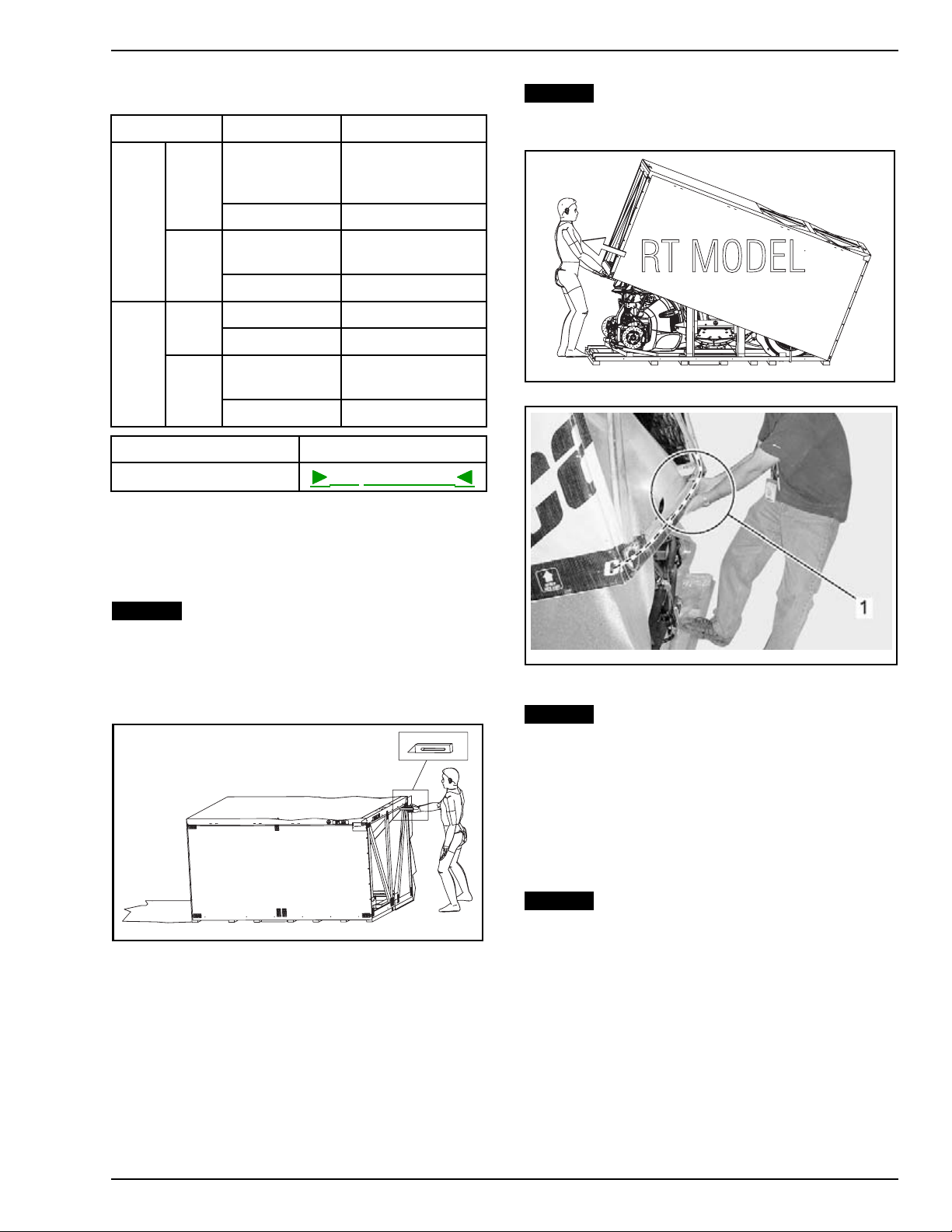
UNCRATING
NOTICE
Do not raise cover vertically. Tilt
cover located on the front side of the vehicle.
Refer to illustration.
rbl2010-002-003
TILT COVER THEN PULL IT
Crate Cover Removal
NOTICE
serious damage to vehicle.
1. Position the crate on a firm, level surface.
2. Carefully cut both ends of crate tarpaulin to locate the front of vehicle.
rbl2010-002-001
CUT BOTH END OF CRATE TARPAULIN
3. Remove all screws holding crate cover to crate
base.
4. Tilt cover from the front side of the vehicle then
pull cover toward you to clear vehicle fascia.
Allowing the crate to drop may cause
rbl2010-002-004_a
FRONT OF VEHICLE
1. Pull crate cover to clear front fascia of th e vehicle
NOTICE
The crate cover must be pulled toward the outside while lifting it to avoid to
damage vehicle.
NOTE: Screws that are used are Robertson
†
#2
type (or equivalent) that require the use of an appropriate screwdriver.
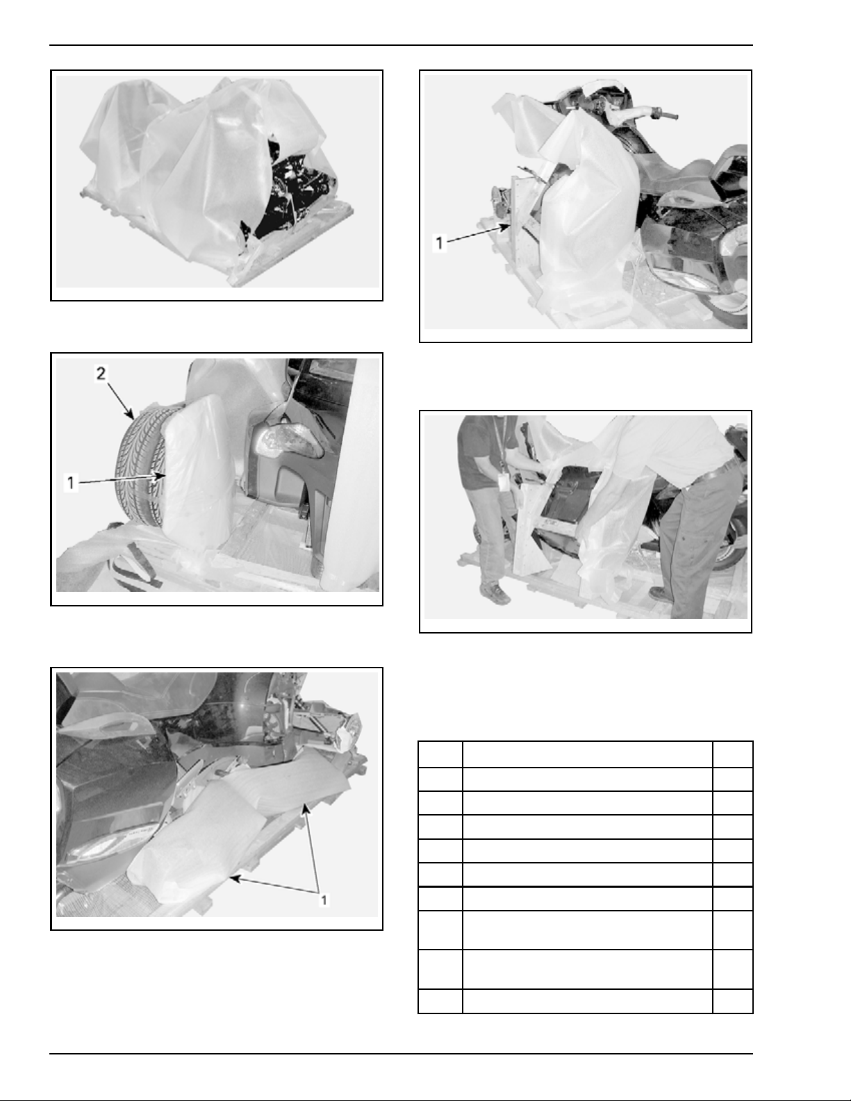
Parts and Sub-crate Removal
NOTICE
bumper and the front fascia.
NOTE: The sub-crate is located on the left side of
vehicle and it contains the front cargo module.
1. Remove protective foam from vehicle.
Be careful not to scratch the cover
† Robertson is a registered trademark of Robertson Inc.
PREDELIVERY 2010-1 3 / 39
Page 4
UNCRATING
All Models
rbl2010-002-005
2. Remove windshield and front wheels from
crate base.
rbl2010-002-006_a
1. Windshield
2. Front wheels
3. Remove front fenders from crate base.
rbl2010-002-008_a
1. Sub-crate
5. Assisted by another person, carefully lift up the
sub-crate.
rbl2010-002-009
Parts Check
1. Ensure that the crate includes the following
items:
ITEM DESCRIPTION (LOCATION) QTY
1
Wheel
lug nut (front wheels)
6
2 Wheel cap (front wheels) 2
3 Bushing (rear suspension) 2
010-002-007_a
rbl2
1. Front fenders
4. Remove all screws holding sub-crate to crate
base.
4
M10 x
5
M10 nu t (rear suspension)
140 (rear suspension)
6 M6 caged nut (front cargo module)
ck M6 x 20 screw (front cargo
Bla
7
module)
d M6 x 20 screw (front cargo
Gol
8
module)
9
vice cover (front cargo module)
Ser
1
1
1
4
2
2
4 / 39 2010-1 PREDELIVERY
Page 5

UNCRATING
Op tion Package
ITEM DESCRIPTION (L
Service cover plastic rivet (front cargo
10
module)
11
Battery post screw (battery) 2
12 M6 x 20 screw (front panels) 2
13 Plastic wash
14
M14 nut (headlights) 2
15
Clip (h eadlights)
16 M8 x 20 screw (
17
Windshield trim 2
18 M6 x 20 screw (windshield)
19 M5 x 20 scre
20 M5 retaining nut (windshield) 2
21 Mudguard 2
22 M6 retain
23 M6 x 20 screw (Mudguards)
ing nut (Mudguards)
OCATION)
er (front panels)
front fenders)
w (windshield)
QTY
2
2
2
8
4
2
4
4
rbl2010-002-010_a
1. Front strap
2. Remove strap retaining side of vehicle to crate
base.
ITEM DESCRIPTION QTY
24 Antenna
25 Antenna rubber cap
26 M6 stainless steel lock washer
1
1
1
Front Wheels Installation
WARNING
SE5 mo
posit
secur
block
No one should be standing in front or at the
back of the vehicle while straps are being cut.
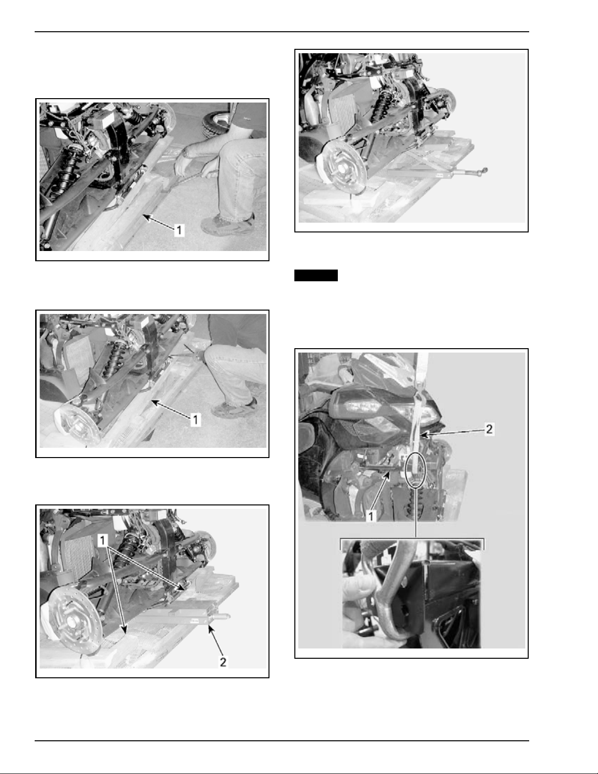
1. Remove strap retaining front of vehicle to crate
base.
dels are automatically set in neutral
ion when engine is stopped. Always
e the rear wheel of vehicle with proper
s to avoid moving.
WARNING
-002-011_a
rbl2010
1. Side strap
3. Remove strap on the RH caliper.
rbl2010-002-012_a
1. Caliper strap
NOTE: The following steps will describe two
methods to install front wheels on vehicle. The
conventional one uses a hydraulic jack and the
alternate one uses a chain block. Use the proper
method according to your shop layout.
PREDELIVERY 2010-1 5 / 39
Page 6
UNCRATING
Co nventional Method
Alternate
Method
1. Remove top crate board located at the front of
vehicle.
rbl2010-002-016
rbl2010-002-013_a
1. Stud to remove
2. Cut second
vehicle us
rbl2010-002-014_a
1. Stud to cut
crate board located at the front of
ing a proper saw.
3. Install a jack under the front lower beam of
frame.
5. Refer to
(CONTINUED)
NOTICE
FRONT WHEELS INSTALLATION
to complete the procedure.
Never lift vehicle by the suspension
arm.
1. Install proper straps on RH and LH lateral supports of vehicle.
rbl2010-002-020_a
1. RH lateral support
rbl2010-002-015_a
d that was cut
1. Stu
2. Hydraulic jack
4. Lift the vehicle.
2. Proper strap
2. Hook straps on an appropriate lifting kit.
3. Lift vehicle using a chain block.
6 / 39 2010-1 PREDELIVERY
Page 7
UNCRATING
Front Wheels Installa tion (continued)
NOTICE
Never lift vehicle by the suspension
arm.
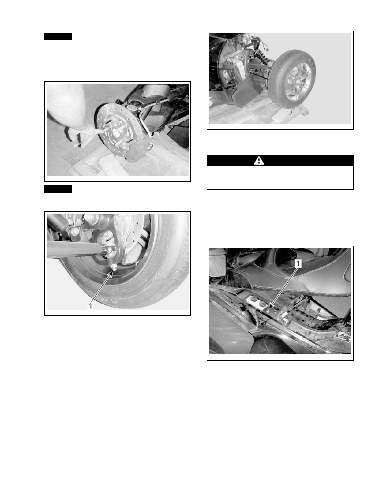
1. Remove nut securing front brake discs to vehicle.
rbl2010-002-017
NOTICE
Be careful not to scratch front wheels
with ball joint cotter pins during wheels installation.
rbl2010-002-019
6. Torque whee
ls lug nuts to 105 N•m (77 lbf•ft).
7. Install wheel caps (from PDI kit).
WARNING
The tires a
rection. D
wheels.
re only designed to rotate in one di-
o not switch the left and right front
Vehicle Removal
-002-018_a
rbl2010
1. Ball joint cotter pin
2. Install front wheels on vehicle.
3. Ensure that the rotation direction shown by the
arrow is respected.
4. Tight
en wheels lug nuts by hand (from PDI kit).
5. Lower vehicle on crate base.
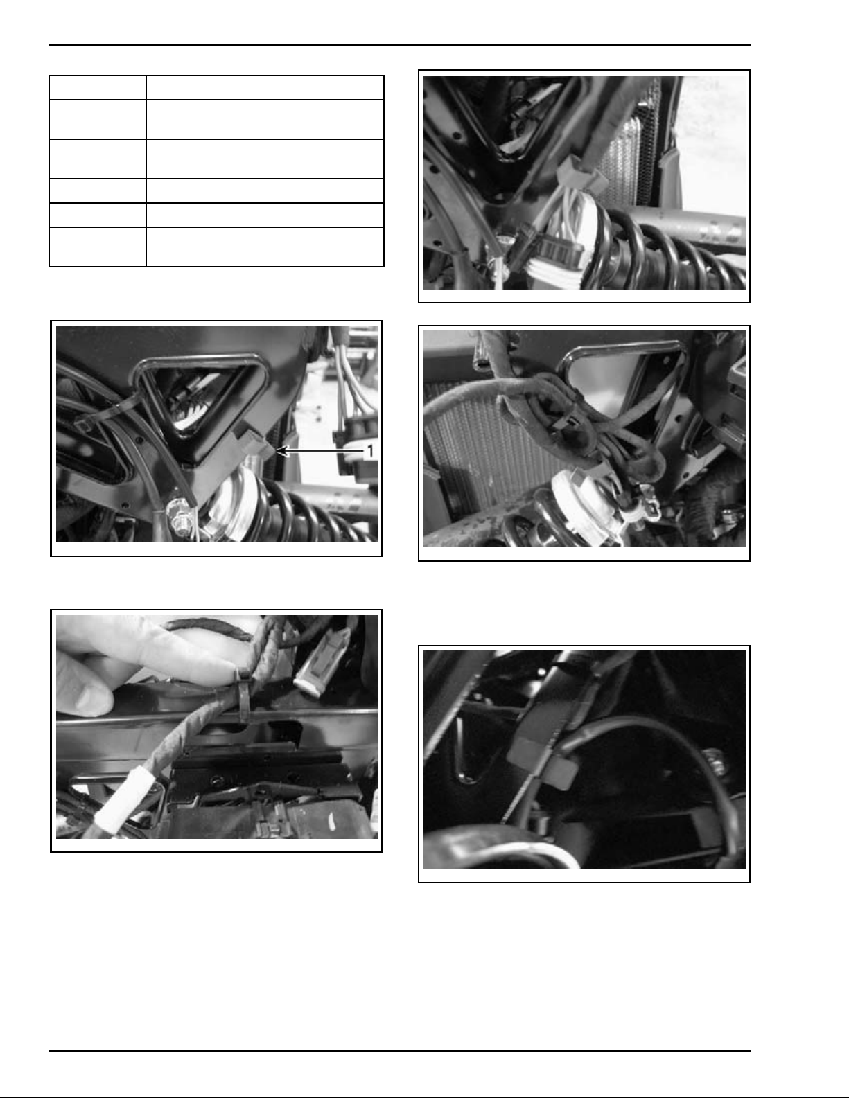
1. Open seat.
2. Locate ACS suspension pneumatic valve then
unscrew cap.
rmo2010-001-056_a
1. Pneu
matic valve
3. From underneath of vehicle, locate the bottom
of the rear shock absorber.
4. Get
the following hardware from the PDI kit:
– M10 x 140 bolt
– M10 nut
stic bushings.
–Pla
5. Install the 2 plastic bushings over the steel
sleeve at the bottom of the shock absorber.
PREDELIVERY 2010-1 7 / 39
Page 8

UNCRATING
6. With the help of another person, gently inflate
the A CS spring while your assistant, from the
LH side of the vehicle, monitors the alignment
of the bottom of the shock absorber (anchoring
holes) with the bottom of the lower brackets.
rbs2010-012-010_a
1. Lower bracket hole
2. Anchoring holes
rbs2010-012-011_a
1. ACS position sensor lever
2. Link
7. Ensure that ACS position sensor lever orientation is correct.
NOTICE
Adding air may create rapid high
changes because of the small air volume
in the ACS spring. The anchoring hole of
shock absorber must NEVER exceed the lower
bracket holes when adding air into ACS spring.
To avoid damaging the ACS system, DO NOT
exceed 551 kPa (80 PSI) into the ACS spring.
rbs2010-012-004_a
1. Lower bracket hole
NOTICE
On RT-S vehicle, exceeding air pressure may damage the ACS suspension sensor
and the ACS spring plate by excessively pull
downward on the ACS suspension sensor, its
lever and its link as illustrated below.
rbs2010-012-001
CORRECT ORIENTATION
rbs2010-012-002_a
INCORRECT ORIENTATION
8. Secure shock absorber as follows:
8.1 Using the passenger grab handles, slightly
lift the rear of the vehicle by HAND to align
both bushings on lower bracket hole.
8.2 Install M10 x 140 bolt.
8.3 Install and torque M10 nut to 48 N•m
(35 lbf•ft).
8 / 39 2010-1 PREDELIVERY
Page 9

rbl2010-002-022_a
1. Shock absorber bo lt
2. Lower bracket
SE5 models a
position wh
secure the r
blocks to a
NOTICE
foot as you
no brake le
pedal is i
NOTICE
en engine is stopped. Always
ear wheel of vehicle with proper
void moving.
Be ready to
move the vehicle since there is
ver on the handlebars. The brake
n front of the right footpeg.
Always move vehicle rearward out of
the crate base.
WARNING
re automatically set in neutral
apply brake with your
PARTSTOBEINSTALLED
rbl2008-003-204_a
1. Bolt and nut holding the bottom section
2. Bolts and nuts holding the top section
NOTE: Be careful not to lose the caged nut located
in the bottom fixation hole of the front cargo module.
2. Open front storage compartment cover.
3. Ensure that the front storage compartment in-
cludes the following items:
– Operator's Guide
– Predelivery (PDI) Check List
–SafetyDVD
– Service covers (2x)
–PDIkit.
– Windshield trim (2x)
– Mudguard (2x)
4. Ensure that the following cables and connec-
tors are accessible prior to installing front cargo
module, cut locking ties if required.
NOTE: Brake pedal applies the brakes for the
three wheels. Press it down to operate.
9. With the help of your assistant, move vehicle
rearward out of the crate base.
rbl2010-002-021_a
PARTS TO BE INSTALLED
Front Cargo Module
1. Remove and discard bolts and nuts holding the
bottom and the top sections of sub-crate.
rbl2010-002-023_a
TO THE FOLLOWING TABLE FOR ITEMS DESCRIPTION
REFER
ITEMS DESCRIPTION
1
2
3
4
AAPTS sensor connector
Horn connector (hidden on
the illustra tio n)
RH and LH auxiliary light connector
- Low beam light (CE)
- Fog light (option package)
DLC connector (B.U.D.S.)
PREDELIVERY 2010-1 9 / 39
Page 10
PARTS TO BE INSTALLED
ITEMS DESCRIPTION
5
6
7
Storage cover actuator connector
(option packag
e)
Storage cover switch connector
(option packag
e)
Storage cover cable
8 12 V power outlet
9
Storage compa
(option package)
rtment light
5. Install headlight harness clip (from PDI kit) on
vehicle frame as shown (on both side).
rbl2010-002-352
LH SIDE
rbl2010-002-350_a
1. Headligh
t h arness clip
6. Cut locking tie holding headlight harness.
rbl2010-002-351
7. Insert headlights harness into clips as shown.
rbl2010-002-353
RH SIDE
8. Do not let auxiliary lights harness hang near
shock absorber. Properly insert it into clips (on
both sides).
rbl2010-002-354
CT INSTALLATION
CORRE
10 / 39 2010-1 PREDELIVERY
Page 11
rbl2010-002-355_a
WRONG INSTALLATION
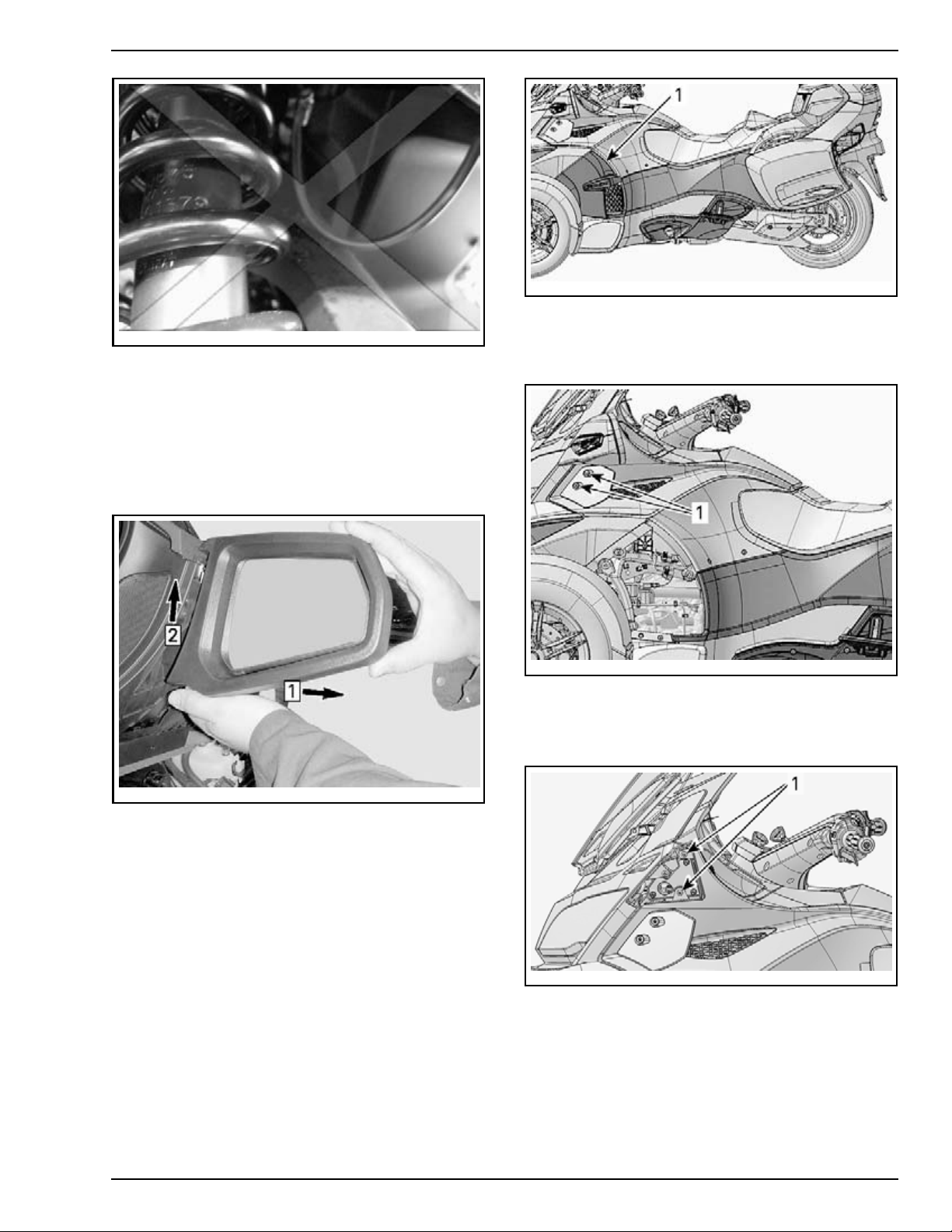
9. Remove mirrors as follows:
9.1 Pull lower part of mirror toward the outside
to unlock it.
9.2 Slide mirror upwards to unhook it from upper slot.
9.3 Disconnect connector.
PARTSTOBEINSTALLED
rbl2010-002-318_a
TYPICAL
1. Middle side panel
11. Remove retaining screws from lower wind deflectors.
rmr2010-038-301_a
Step 1: Pull toward the outside
Slide upwards
Step 2:
10. Remove middle side panels as follows:
10.1 P ull p
anel toward the outside to remove
m grommets at the front.
it fro
10.2 Unhook the rear.
rbl2010-002-319_a
TYPICAL
1. Retaining screws of wind deflector
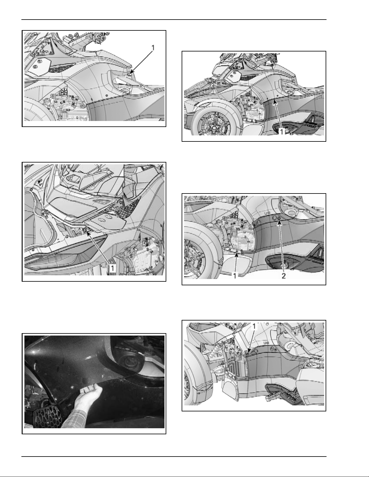
12. Remove upper retaining screws from top side
panels.
rbl2010-002-320_a
TYPICAL
1. Upper retaining screws
13. Remove rear retaining screw from top side
panels.
PREDELIVERY 2010-1 11 / 39
Page 12
PARTS TO BE INSTALLED
rmr2010-038-006_a
TYPICAL
1. Rear retaining screw
14. Remove front retaining screw from top side
panels.
16. Remove top side panels by lifting them upwards.
-009_a
rmr2010-038
TYPICAL
1. Top side panel
17. Remove fron
t retaining screw of LH rear side
panel.
18. Remove upper retaining screw and washer
from LH rear side panel.
rbl2010-002-321_a
TYPICAL
1. Front r
etaining screw
15. Pull out lower part of top side panel to remove
it from grommets.
NOTE: D
o not remove lower screws from top side
panel.
rbl2010-002-305
rmr2010-038-010_a
1. Front retaining screw
2. Upper retaining screw
19. Remove front plastic rivet from LH rear side
panel.
2010-038-011_a
rmr
1. Front plastic rivet
20. Open LH storage compartment cover.
21. Remove rear retaining screws from LH rear
side panel.
12 / 39 2010-1 PREDELIVERY
Page 13

rmr2010-038-012_a
1. Rear retaining screws
22. Remove top retaining screw of LH rear side
panel.
PARTSTOBEINSTALLED
rmr2010-038-022_a
TYPICAL
1. Upper retaining screw
25. Remove middle retaining screws from front
fascia.
rmr2010-038-013_a
1. Top reta
NOTICE
rbl2010-002-356_a
LH REAR SID E PANEL
1. Lower tabs
ining screw
Be careful not to break lower tabs.
23. Remove LH rear side panel from vehicle.
24. Remove upper retaining screws from front
fascia.
rmr2010-038-023_a
TYPICAL
1. Middle retaining screw
26. Remove lower retaining screws and washers
from front fascia.
rmr2010-038-024_a
TYPICAL
1. Lower retaining screw
27. Remove front fascia from vehicle.
28. Use the following hardware to fix front cargo
module on vehicle.
PREDELIVERY 2010-1 13 / 39
Page 14

PARTS TO BE INSTALLED
CE Models
rbl2010-002-100_a
1. Black M6 screws from PDI kit
2. Gold M6 screws from PDI kit
3. M6 caged nut from PDI k it
NOTE: The second caged nut is already installed
on front cargo module.
29. Assisted by another person, position front
cargo module into support slots of vehicle.
30. Connect the following front cargo module connectors and cable:
– AAPTS sensor connector
– Horn connector
– RH and LH auxiliary light connector (CE and
Option Package)
– DLC connector (B.U.D.S.) stowed in its re-
ceptacle
– Storage cover actuator connector (option
package)
– Storage cover switch connector (option
package)
– Storage cover cable
– 12 V power outlet
– Storage compartment light (option pack-
age).
31. Install auxiliary light adjustment cable as follows:
31.1 Install adjustment cable through hole in
panel.
31.2 Tighten nut securing adjustment cable
(from PDI kit).
rmo2010-001-009_d
LEFT SIDE SHOWN
1. Install through this hole
32. Install caged nut (from PDI kit) on a bottom
hole of storage compartment.
33. Install gold M6 screws to secure bottom of
storage compartment.
34. Do not tighten gold M6 screws for the moment.
0-038-026_a
rmr201
1. Gold M6 screws
35. Install black M6 screws to secure top of storage compartment.
rmr2010-038-025_a
1. Black M6 screws
14 / 39 2010-1 PREDELIVERY
Page 15

36. Torque upper and lower M6 screws to
4.5 N•m (40 lbf•in).
37. Do not reinstall body panels for the moment,
follow
TION
ule as per
TINUED)
BATTERY CHARGING AND INSTALLA-
procedure then finalize front cargo mod-
FRONT CARGO MODULE (CON-
procedure.
Battery Charging and
Installation
WARNING
Always connect RED positive cable first and
then BLACK negative cable.
CAUTION Neve
while instal
led on vehicle.
r charge or boost battery
PARTSTOBEINSTALLED
rbl2010-002-302_a
4. Unplug pillion rider (passenger) switch.
NOTICE
Always charge battery before its in-
stallation on the vehicle.
NOTICE
Make sure not to squeeze battery ca-
bles between vehicle components.
NOTE: The ba
it needs to b
ery. To perf
need to rem
NOTE: Refer to the latest edition of
ROADSTER BATTERIES SERVICE BULLETIN
ttery is filled and serviced. However
e fully charged prior to vehicle deliv-
orm charging of the battery you will
ove battery from vehicle.
CAN-AM
for
proper activating, charging and maintenance procedures.
1. Open seat
2. Disconne
ct cylinder from seat base.
rbl2010-002-304_a
1. Pillion rider switch connector
5. Remove
LH side
the battery access panel located at the
of vehicle.
6. Disconnect rear heated grip switch if applicable.
rmr2010-027-003_a
rbl2010-002-301_a
1. Cylinder
TYPICAL - LH SIDE OF VEHICLE
1. Battery access panel
2. Battery access panel retaining screws
3. Rear heated grips switch
3. Lift seat and secure it using a piece of wood.
NOTICE
Discard bag containing battery hardware from underneath battery rubber strap.
This hardware supplied with battery must not
be installed. Use post screws from PDI kit
(longer).
PREDELIVERY 2010-1 15 / 39
Page 16

PARTS TO BE INSTALLED
7. Install battery screws on battery posts (from
PDI kit).
8. Remove battery holding strap.
9. Cut locking ties securing battery cables together.
10. Move electrical harness outward to make
room around battery.
rbl2010-002-310_a
11. Lift the leading edge of the battery and care-
fully pull it out of the battery rack.
17. Close RED rubber boot cover.
rbl2010-002-032
18. Connect BLACK (-) negative battery cables as
shown:
18.1 Position BLACK (-) main battery cable
(large) on negative (-) battery post.
18.2 Position BLACK (-) regulator/rectifier ca-
ble (small) on negative (-) battery post.
rbl2010-002-315_a
rbl2010-002-311_a
12. Charge battery. Refer to
BATTERIES SERVICE BULLETIN
NOTICE
It is of the upmost importance for the
CAN-AM ROADSTER
.
1. BLACK (-) main battery cable (large)
2. BLACK
(-) regulator/rectifier cable (small)
18.3 Tighten negative post battery screw to
4N•m (35lbf•in).
19. Inst
all battery holding strap.
battery life span that the battery initial charging
be performed.
13. Install charged battery in battery rack.
WARNING
Always connect RED (+) cable first.
14.Co
15. Tighten positive post battery screw to 4 N•m
16. Apply
16 / 39 2010-1 PREDELIVERY
nnect RED (+) positive battery cables.
(35 lbf•in).
DIELECTRIC GREASE (P/N 293 550 004) on
battery posts.
Page 17

PARTSTOBEINSTALLED
rbl2010-002-316_a
1. Battery holding strap
20. Position electrical harness in their original location.
rbl2010-002-317
21. Connect rear heated grip switch if applicable.
22. Install the battery access panel.
23. Connect pillion rider (passenger) switch.
24. Connect shock absorber on seat base.
rmo2010-001-009_e
LEFT SIDE SHOWN
1. M6 x 20 screw and plastic washer (from PDI kit)
3. Torque front fascia retaining screws to 2.5 N•m
(22 lbf•in).
4. Torque top side panel retaining screws to
2.5N•m (22lbf•in).
5. Install service covers (from PDI kit) as follows:
5.1 Open front storage compartment cover.
5.2 Insert upper tabs of service cover into the
vehicle grooves.
5.3 Push lower portion of service cover then
install plastic rivet (from PDI kit).
NOTICE
For the RH service cover, pay at-
tention not to damage the FCS switch.
Front Cargo Module
(continued)
1. Install the following body panels as the reverse
of removal procedure:
– Front fascia
– LH rear side panel
– Top side panels
– Middle side panels
– Mirrors.
2. Install M6 x 20 screws and plastic washers
(from PDI kit) to secure side panels.
PREDELIVERY 2010-1 17 / 39
rmr2010-038-021_a
1. RH service cover
2. Plastic rivet
Front Fenders
1. Cut locking tie that hold harness bracket on
fender.
Page 18

PARTS TO BE INSTALLED
rbl2010-002-024_a
1. Locking tie
2. Position front fender on vehicle.
3. Route front brake hose on fender hook.
rbl2010-002-026_a
1. Fender screws to hold fender
2. Harness bracket
3. Fender screw to hold harness bracket and fender
8. Connect fender light connector on vehicle.
9. Secure connector to vehicle.
-002-025_a
rbl2010
1. Brake hose
2. Fender hook
4. Instal
l 3 fender screws (from PDI kit) by hand to
hold fe
nder in place, refer to illustration.
5. Align harness bracket on the remaining hole
then install a fender screw (from PDI kit).
6. Torque all fender screws to 24 N•m (18 lbf•ft).
7. Prope
rly insert cable grommets on harness
et.
brack
rbl2010-002-027_a
1. Fender
light connecto r
10. Carry out the same procedure for the other
side.
Mudguards
1. From inside mudguards, check for proper loca-
tion (LH or RH side).
18 / 39 2010-1 PREDELIVERY
Page 19

PARTSTOBEINSTALLED
3. Torque windshield retaining screws to 4.5 N•m
(40 lbf•in).
4. Place a sheet of paper on windshield to protect
it, refer to illustration.
rbl2010-002-029_a
1. Installation side
2. Position mudguards on proper fender.
3. Secure mudguards using M6 x 20 screws and
M6 retaining nuts (from PDI kit).
rmr2010-038-026_b
1. Mudguard
NOTICE
If this precaution is not taken, scratch
on the windshield may occur and will not be
covered under warranty.
rbl2010-002-028
5. Install windshield trim panels as follows:
5.1 Insert M5 retaining nut (from PDI kit) on
trim panel.
5.2 Insert trim panel into windshield slot.
5.3 Push trim panel upwards.
5.4 From inside windshield, secure trim panel
using M5 x 20 screw (from PDI kit).
Windsh
1. Align
ield
windshield on windshield support.
2. Install M6 x 20 screws (from PDI kit) to secure
windshield.
rmr2010-038-043_a
1. Windshield trim panels screws
5.5 Tor
que windshield trim panel screw to
N•m (22 lbf•in).
2.5
6. Remove sheet of paper.
rmr2010-038-045_a
1. Windshield M6 x 20 screws
PREDELIVERY 2010-1 19 / 39
Page 20

PARTS TO BE INSTALLED
RT Audio & Convenience and RT-S Models
Antenna (Option Package)
1. Detach antenna from the sub-crate .
rbl2010-002-033_a
1. Antenna
2. Insert the M6 stainless steel lock washer (fro m
PDI kit) and rubber cap onto antenna.
3. Apply one
800 060) o
NOTICE
ening problems, do not add the threadlocker in
other location and do not apply more than the
recommended quantity of threadlocker.
drop of L OCTITE 243 (BLUE) (P/N 293
n the first thread of t h e a n t e nna.
To avoid hydro-lock or further loos-
rbl2010-002-031_a
1. Rubber cap
2. Antenna
5. Tighten antenna then install rubber cap on vehicle (tighten by hand) .
Hang Tag and Safety Labels
This vehicle comes with a hang tag and labels
containing important safety information. The
labels are considered permanent parts of the
vehicle and should not be removed. Hang tag is
to be removed by the owner only.
Any person who rides this vehicle should read and
understand all the information given on hang tag
and safety labels before riding.
Safety labels of several language can be chosen
by customer, according to availability.
rbg2010-007-002_a
1. Drop of LOCTITE 243
2. M6 stainless steel lock washer
4. Posit
ion antenna on RH side of rear carg o mod-
ule.
rmo2008-001-102
Licence Plate
NOTE: When a license plate needs to be installed
or replaced, ensure to install new damping pad
(P/N 293 740 028).
1. Remove existing plate on vehicle (if applicable).
2. Pea
20 / 39 2010-1 PREDELIVERY
l off backing of new damping pad.
Page 21

FLUIDS
Vehicle Decals
1. Install decals on vehicle according to customer
country language and local legislation.
2. Ensure that the new decals are installed at the
same location and over the factory installed decals.
rmo2008-002-509_a
1. Damping pad backing
3. Position new damping pad on vehicle plate support.
rmo2010-001-053_a
1. Plate su
pport
4. Secure upper portion of license plate on vehicle
plate support using existing hardware.
Key Barrel - Trailer RT 622
An extra key barrel is supplied with each Spyder
RT. This allows the use of the vehicle key for the
trailer.
Refer to the trailer RT 622 PDI Bulletin for all the
details.
FLUIDS
General Guidelines
All fluids (except fuel) have already been filled
at factory, it is only necessary to validate them.
However, if refill is needed, refer to the appropri-
ROADSTER SHOP MANUAL
ate
procedure.
Fuel
1. Unlatch and lift seat.
2. Add fuel in the fuel reservoir.
for the proper
rmo2010-001-051_b
1. Fuel cap
rmo2010-001-054_a
1. Existing hardware
5. Squeeze license plate and support together at
the center.
Recommended Fuel
Use unl
tainin
The gas
tane nu
eaded gasoline or oxygenated fuel con-
g no more than 10% ethanol or methanol.
oline used must meet the following oc-
mber:
Accessories Installation
1. Install accessories (if any) as per their installation instructions (included in each kit).
2. Install any other equipment required by law (if
any).
PREDELIVERY 2010-1 21 / 39
Page 22

FLUIDS
FUEL OCTANE RAT
INSIDE NORTH AMERICA
Recommended Minimum
91
(RON + MON)/2)
Use premium unleaded fuel for optimum engine
performance.
FUEL OCTANE R
OUTSIDE NORTH AMERICA
Recommended Minimum
95 RON 92 RON
Use premium unleaded fuel for optimum engine
performance.
ING
87
(RON + MON)/2)
ATING
WARNING
Never top off the fuel tank before placing
the vehicle in a warm area. As temperature
increases, fuel expands and may overflow.
Fuel is flammable and explosive under certain conditions. Always wipe off any fuel or
oil spillage from the vehicle.
NOTICE
formance and damage critical parts in the fuel
system and engine.
Other fuel can degrade vehicle per-
NOTICE
To avoid damaging the clutch, do not
use a motor oil meeting the API service SM or
ILSAC GF-4 classification. Clutch slippage will
occur. Motorcycle oils designed for use with a
wet-clutch are the best alternative.
Engine Oil Level Verification
WARNING
Before starti
well ventilat
come from the
anti corrosi
and engine bu
NOTICE
necessary t
sure that th
ature. If oi
at operatin
tween lowe
NOTICE
ification is performed when the engine is cold.
1. Park the vehicle on a level surface.
2. Remove the LH middle side panel as follows:
2.1 Pull pane
then unho
ng vehicle ensure vehicle in a
ed area or is outside. Smoke will
engine for 10 minutes as the
on coating on the exhaust system
rns off.
For an accur
ate oil level reading, it is
o ride vehicle for 5–7 minutes to en-
e engine is at its operating temper-
l level is verified when vehicle is not
g temperature, oil level must be be-
r and upper marks on dipstick.
Never add oil in the engine if the ver-
l out of its grommets at the front
ok the rear.
Engine Oil
NOTICE
Spyder r
differe
day. Pro
this sec
The proce
oadster oil level and replacing oil are
nt from most of the motor vehicles to-
perly follow instructions provided in
tion.
Recommended Engine Oil
NOTE: For SM5 models, the same oil lubricates
the engine, the gearbox and the clutch.
NOTE: Fo
engine,
drauli
Use
(P/N 293 600 121)
If not available, use a 5W 40 semi-synthetic (minimum) or synthetic motorcycle oil meeting the requirements for API service SL, SJ, SH or SG classification. Always check the API service label on
the oil container.
r SE5 models, the same oil lubricates the
the gearbox, the clutch and the HCM (hy-
c control module).
XPS SYNTHETIC BLEND OIL (SUMMER GRADE)
dures for checking the
.
rmr2010-038-003_a
1. Middle side panel
3. With the engine already at normal operating
temperature, start engine and let it run for at
least 30 seconds.
NOTE: Running engine for at least 30 seconds al-
lows the suction oil pump to drain the oil from the
engine crankcase back into the oil tank. Not carrying out this step could result in overfilling the engine oil.
4. Stop engine.
5. Unscrew and remove the oil dipstick.
22 / 39 2010-1 PREDELIVERY
Page 23

rmo2010-001-062_a
1. Oil dipstick
2. Oil tank
6. Wipe off the dipstick.
7. Reinsert and completely screw in the dipstick
to assure an accurate reading.
8. Unscrew and remove the dipstick again.
9. Check the oil level on the dipstick. It should be
near or equal to the upper mark.
FLUIDS
Clutch Fluid (SM5 Model)
Recommended Clutch Fluid
Use DOT 4 brake fluid from a sealed container.
An opened container may be contaminated or may
have absorbed moisture from the air.
Clutch Fluid Level Verification
The clutch fluid reservoir is near the reverse button on the left handlebar.
1. Park the vehicle on a firm, level surface.
2. Set the handlebar in the straight ahead position.
3. Wipe clean the cap area.
4. Use the Phillips head screwdriver located in the
toolkit.
5. Unscrew cap retaining screws.
08-011-102_a
rmr20
1. Full
2. Add
3. Opera
ting range
If Oil Level is at or Near Upper Mark:
– Properly insert and tighten dipstick.
all the LH middle side panel as the reverse
–Inst
moval.
of re
If Oil Level is Under Operating Range:
–Adda
small amount of recommended oil.
– Repeat the previous steps until oil level reaches
the dipsticks upper (F) mark. Do not overfill.
– Properly insert and tighten dipstick.
tall the LH middle side panel as the reverse
–Ins
emoval.
of r
rmo2010-001-005
6. Carefully remove cap. Pay attention not to drop
the cap seal.
7. Look inside the reservoir to see the fluid level.
8. Level should be within the maximum level line
and the minimum level indicated by the protuberances in the bottom of reservoir.
PREDELIVERY 2010-1 23 / 39
Page 24

FLUIDS
Coolant Level Verification
WARNING
When opening the reservoir, the coolant can
be very hot and spray out if the engine is hot.
In order to avoid getting burned, check the
coolant level when the engine is cold.
rmo2010-001-006_a
FLUID REMOVED FOR CLARITY PURPOSE
1. Maximum level line
2. Minimum level (top of protuberance)
9. Add recommended fluid as required. Do not
overfill.
WARNING
Avoid getting brake fluid on skin or in eyes
— it may cause severe burns. In case of contact with the skin, wash thoroughly. In case
of contact with the eyes, immediately rinse
with plenty of water for at least 10 minutes
and then consult a doctor immediately.
10. Immedia
11. Ensure that the seal located inside the cap is
collapsed.
12. Reinstall the cap to the reservoir.
13. Tighte
14. Wipe off reservoir if necessary.
tely wipe up spills if necessary.
n cap screws.
1. Park the vehi
cle on a firm, level surface.
2. Open the front storage compartment.
3. Remove the plastic rivet from the right service
cover.
rmr2010-038-021_a
1. Right service cover
2. Plastic rivet
4. Lift lower portion of service cover then pull it
toward the front.
5. Check the coolant level. Coolant must be visible without exceeding the MAX. level mark.
Engine
Coolant
WARNIN
G
When opening the reservoir, the coolant can
be very hot and spray out if the engine is
hot. In order to avoid getting burned, check
coolant level when engine is cold.
Recommended Coolant
The cooling system must be filled with distilled
water and antifreeze solution (50% distilled water,
50% antifreeze).
For best performance, use
COOLANT (P/N 219 700 362)
BRP PREMIXED
24 / 39 2010-1 PREDELIVERY
rmo2008-001-039_a
CAL
TYPI
1. Coolant MAX. level mark
2. Coolant m ust be visible
6. If re
quired, add recommended coolant until it
isible in the reservoir without exceeding the
is v
. level mark. Use a funnel to avoid spillage.
MAX
ot overfill.
Do n
7. Reinstall the service cover.
Page 25

Brake Fluid
Avoid contact o
because it may c
of contact with
case of contac
rinse with ple
utes and then c
nty of water for at least 10 min-
SET-UP
WARNING
fbrakefluidwithskinoreyes
ause severe burns. In case
the skin, wash thoroughly. In
t with the eyes, immediately
onsult a doctor immediately.
NOTICE
Do not overfill brake fluid reservoir.
Recommended Fluid
Use only DOT 4 brake fluid from a sealed container. An opened container may be contaminated
or may have absorbed moisture from the air.
NOTICE
To avoid serious damage to the braking system, do not use non-recommended fluids. Brake fluid can damage plastic and painted
surface. Handle with care.
Brake Fluid Level Verification
WARNING
Clean fille
DOT 4 brake f
1. Park the vehicle on a firm, level surface.
2. Unlatch and lift the seat.
3. Check the brake fluid level in both reservoirs,
near the back of the seat. They should both be
above the MIN. mark.
r cap before removing. Use only
luid from a sealed container.
rmo2010-001-091_a
1. Brake fluid MAX. level mark
2. Brake fluid MIN. level mark
rmo2010-001-092_a
A. Operating range
6. Immediately wipe up spills if necessary.
7. Reinstall both caps of the reservoir.
8. Close the seat and ensure it is fully latched.
SET-UP
Tire Pressure
WARNING
Low pressure may cause tire to deflate and
rotate on wheel. Overpressure may burst the
tire. Always follow recommended pressure.
NOTICE
cold before using the vehicle.
NOTE: Tire pressure changes with temperature
and altitude. Recheck pressure if one of these
conditions has changed (e.g., significant weather
rmo2010-001-013_b
1. Brake fluid reservoir
4. Clean
the filler caps before removing.
5. Add recommended fluid as required. Do not
change, driving in the mountains).
1. Inflate tires to the specified air pressure. Refer
to the following table.
COLD TIRE PRESSURE RECOMMENDATION
overfill.
Nominal.: 103 kPa (15 PSI) Nominal.: 193 kPa (28 PSI)
PREDELIVERY 2010-1 25 / 39
Always check pressure when tires are
FRONT REAR
Page 26

ADJUSTMENTS
Brake Disc Cleanup
1. Clean front and rear brake discs using PULLEY
FLANGE CLEANER (P/N 413 711 809)
.
NOTICE
A thin layer of anticorrosion treatment is present on the brake discs and must
be removed before using the vehicle. Not conforming to this procedure may lead to a brake
chattering squeaking and brake pad replacement would be necessary.
ADJUSTMENTS
Guidelines
All adjustments have already been performed
at factory. It is only necessary to validate them.
However, if readjustment is needed, refer to the
appropriate
ROADSTER SHOP MANUAL
proper procedure.
Drive Belt
NOTICE
all parts at room temperature and the rear
wheel lifted of the ground.
1. Place vehicle on a level surface.
NOTE: The area must be protected against wind
and must have a very low background noise.
2. Set transmission to NEUTRAL.
3. Lift rear of vehicle by the frame until rear wheel
is off the ground.
Always verify drive belt tension with
for the
529036115
5. Enter the following specifications to program
the meter.
MASS WIDTH SPAN
8.4 g/m 28.0 mm /R 1028 mm
rmr2008-031-002
SONIC TENSION METER DISPLAY
NOTE: Ref
set the in
er to the manufacturer's instructions to
formations into the device.
6. Turn rear wheel to align a wheel spoke with the
swing arm.
NOTICE
Do not lift under rear shock absorber.
Always lift by the frame. Refer to illustration.
rmr2008-031-003
TYPICAL - SWING ARM ALIGNS WITH A SPOKE
7. Position the sensor under the LH passenger
footrest and hold the sonic tension meter sen-
rmr2008-030-009
TYPICAL - LIFT BY THE FRAME
sor approximately 1 cm (1/2 in) from belt or
closer without touching the belt.
4. To check the drive belt tension use the BELT
TENSION METER (P/N 529 036 115)
.
26 / 39 2010-1 PREDELIVERY
Page 27

rbs2010-006-001
SPYDER RT
ADJUSTMENTS
8. Tap the belt to make the belt vibrate and read
the measurement.
9. Take a secon
d measurement to confirm the first
one.
10. Note the first value obtained at step 8 if the
measurement at step 9 is w ithin ±25N.
NOTE: If the second value is not within ±25N, re-
peat steps 8 and 9.
11. Repeat mea
spokes to
surements at every spoke (3
tal).
The average of the 3 obtained values (at the 3
spokes) must be within the following range:
DRIVEBELTTENSION
(PARTS AT ROOM TEMPERATURE AND
REAR WHEEL LIFTED)
450N ± 150N
If the tension of drive belt is out of specification,
adjust drive belt as per
JUSTMENT
the proper
. Refer to
CAN-AM ROADSTER SHOP MANUAL
DRIVE BELT TENSION AD-
DRIVE SYSTEM
section in
Clutch Lever
NOTE: The distance between the clutch lever and
handgrip can be adjusted from position 1 (greatest
distance) to position 4 (smallest distance).
1. Adjust the clutch lever as per the owner’s preference.
1.1 Push the clutch lever forward to release
the adjuster dial. Hold in position.
1.2 Turn the adjuster dial to the desired posi-
tion aligning the dial number with the dot
on the lever.
1.3 Release the clutch lever.
rmo2010-001-033_a
CLUTCH LEVER ADJUSTMENT
1. Clutch lever
2. Adjuster dial
3. Dot
Suspension
WARNING
Left and right adjusting cams must always
be set at the same position. Never adjust
one adjusting cam only. Uneven adjustment
can cause poor handling and loss of stability,
which could lead to an accident.
Front Suspension
NOTICE
front of vehicle using a jack to extend the suspension. This will ease turning the adjustment
cam and will prevent a potential breakage of
the adjustment plate.
1. Adjust the spring preload as per the owner’s
.
preference.
1.1 Place the vehicle on a level surface.
1.2 Engage the parking brake.
1.3 Adjust the spring preload by turning the
rmr2008-029-002
FRONT SUS PE N S ION ADJUSTING WRENCH
Before adjusting suspension, lift the
cam with the adjusting wrench (stored in
the tool kit).
PREDELIVERY 2010-1 27 / 39
Page 28

ADJUSTMENTS
Models Without Compressor (Manual
Adjustment)
North American Models
WARNING
MINIMUM PRESSURE 10 PSI / 70 kPa
Do not exceed recommended pressure by 10 PSI / 70 kPa
PASSENGER + CARGO (lb /kg)
PSI/kPa
PSI/kPa PSI/kPa
40/275 50/345 60/415
50/345
60/415 70/485 80/555
60/415
704902072
LOAD
Lb/Kg
150/70 20/135
200/90 30/205
DRIVER
250/115
0 100/45 150/70 200/90 250/115
PSI/kPa
40/275
70/485
PSI/kPa
70/485
80/555
90/625
rmr2008-029-003
FRONT SUSPENSION CAM ADJUSTMENT
rmr2008-030-004_c
A. Smooth adjustment (position 1)
B. Hard adjus
RECOMMENDED FRONT SHOCK ADJUSTMENT
68 kg (150 lb)) rider with cargo 3
91 kg (200 lb) rider with cargo
Rider w
ACS Rea
tment (position 5)
LOAD
68 kg (150 lb) rider 1, 2
91 kg (20
ith passenger and cargo
0 lb) rider
CAM
POSITION
3
4
5
r Suspension
The suspension pressure is adjustable by deflatingorinflatingtheairspring. Useanaircompressor and a pressure gauge.
ten suspension, reduce the air pressure and
To sof
den suspension, increase air pressure.
to har
1. Adjust the air spring as per the owner’s preference.
2. Refer to the following chart for proper adjustment.
NOTICE
Do not exceed the maximum allowed
pressure. This might damage the air suspension.
NOTE: When adjusting the pressure, do not put
your weight on the vehicle and do not load cargo
in the storage compartment.
The air spring is connected directly to an air hose
with a schrader valve located under the seat.
rmo2010-001-056_a
1. Schrader valve
NOTE: On
ment, it
setting
the fac
fer to t
for det
models equipped with a remote adjust-
is not necessary to adjust the suspension
. The air spring will inflate automatically at
tory setting after the vehicle start up. Re-
he
2010 SPYDER RT OPERATOR'S GUIDE
ails.
Lights
Headlights Aiming Verification
1. Positi
on the vehicle 10 m (33 ft) in front of a test
ce (wall or screen).
surfa
28 / 39 2010-1 PREDELIVERY
Page 29

ADJUSTMENTS
CE Models (Low Beam)
CE Models (High Beam)
B
A
90°
rmo2010-001-007_a
A. 10 m (33 ft)
B. 91 kg (200 lb)
90°
rmo2010-001-008_a
2. On the test surface, trace a mark at 642 mm
(25.3 in) above ground then another at 732 mm
(28.8 in).
3. Have someone weighing at least 91 kg (200 lb)
sit on the operator's position.
4. Select low beam.
5. Beam aiming is correct when the focus point
(brightest spot) of the headlight reflection is
within the marks.
B
A
90°
rmo2010-001-007_a
A. 10 m (33 ft)
B. 91 kg (200 lb)
90°
rmo2010-001-008_a
2. On the test surface, trace a mark at 415 mm
(16.3 in) above ground then another at 515 mm
(20.3 in).
3. Have someone weighing at least 91 kg
(200 lb)sit on the operator's position.
4. Select low beam.
5. Beam aiming is correct when the focus point
(brightest spot) of the headlight reflection is
within the marks.
2 3
1
rmo2010-001-302_a
TYPICAL REFLECTION ON SURFACE TEST
1. Groun
2. Focus point
3. Focus point within the marks
A. Mark a
B. Mark at 732 mm (28.8 in) above ground
d
t 642 m m (25.3 in) above ground
A
B
NOTE: This verification is valid for either left-hand
or right-hand traffic regulations.
1. Posi
tion the vehicle 10 m (33 ft)in front of a test
ace (wall or screen).
surf
2 3
1
rmo2010-001-302_a
TYPICAL HEADLIGHT REFLECTION ON SURFACE TEST
1. Groun
2. Focus point
3. Focus point within the marks
A. Mark a
B. Mark at 515 mm (20.3 in) above ground
d
t 415 mm (16.3 in) above ground
A
B
NOTE: As the low beam and high beam are sep-
arate units, this verification is valid for either lefthand or right-hand traffic regulations.
w the same procedure as per the low beam
Follo
elect the high beam.
but s
PREDELIVERY 2010-1 29 / 39
Page 30

ADJUSTMENTS
All Models
Beam aiming is correct when the focus point
(brightest spot) of the headlight reflection is
within the marks.
2 3
B
1
rmo2010-001-301_a
TYPICAL HEADLIGHT REFLECTION ON SURFACE TEST
1. Ground
2. Focus point
3. Focus point within the marks
A. Mark at 800 mm (31.5 in) above ground
B. Mark at 850 mm (33.5 in) above ground
A
Headlights Aiming Adjustment
1. Each headlight can be adjusted by turning the
adjustment screws located behind the middle
side panel.
2. Remove both middle side panels. Refer to
FRONT CARGO MODULE INSTALLATION
.
3. Use the Allen key located in toolkit.
4. Insert the Allen key through the rear adjustment
hole into the adjustment screw.
rmo2010-001-009_b
LEFT ADJUSTMENT SCREW
1. To raise headlight beam
rmo2010-001-009_a
LEFT SIDE SHOWN
1. Adjus
t th rough this hole
5. Turn the adjustment screw clockwise to raise
the headlight beam and conversely turn the adjustment screw counterclockwise to lower the
headlight beam. Adjust both headlights evenly.
:
NOTE
same
The high beam becomes adjusted at the
time.
rmo2010-001-009_c
ADJUSTMENT SCREW
1. To lower headlight beam
6. Reinstall middle side panels as the reverse of
removal procedure.
B.U.D.S. Programming
NOTE: MPI-1 will not allow communication with
these vehicles. Only the MPI-2 must be used.
529036019_a
30 / 39 2010-1 PREDELIVERY
Page 31

NOTE: Do not use D.E.S.S. POST INTERFACE
(P/N 529 036 019)
with the KW2000 (500K) protocol. DESS Post Interface will not allow communicationwiththesevehicles.
NOTE: B.U.D.S.isnotusedtoprogramthehard
keys (included keys are ready to use).
Use B.U.D.S. to
– Enter Customer's Name
– Reset Trip Hours and Trip Distances
– Reset Last Service
– Set Speedometer Units
– Set Cluster Language
– Check fault codes (if any).
ADJUSTMENTS
Connecting PC to Vehicle
1. Remove service cover from vehicle.
2. Connect the PC to vehicle. Refer to the latest
edition of
WARE AND COMMUNICATION TOOLS
CAN-AM ROADSTER B.U.D.S. SOFT-
for the
proper connecting procedure.
3. Ensure that the status bar shows the proper
protocol and proper ECU number. Refer to the
following table.
MODEL PROTOCOL
SM5
SE5
KW2000 500K
KW2000 500K 6
ECU
QUANTITY
5
4. Press READ DATA button from the tool bar to
initiate communication with the vehicle.
Entering Customer's Name
NOTE: Wh
tion dis
for exam
tomer's
be visib
1. Click on the VEHICLE tab to open the vehicle
information page.
en starting the vehicle, the multifunc-
play will show the name of the customer;
ple: “HI JOHN SMITH”. If the cus-
name is not programmed, only “HI” will
le when turning the vehicle ON.
vbl2006-007-001
2. Type the na
vbl2006-007-002
me of the customer.
3. Click on WRITE DATA to save the information
in the vehicle ECM.
NOTE: A
B.U.D.
on the s
fter you are finished typing the name,
S. automatically updates the Delivery Date
creen.
Resetting Trip Hours and Trip Distances
1. Ensure that the VEHICLE tab is selected.
2. Click
on the RESET TRIP buttons to reset the
mation.
infor
rbl2008-003-003
PREDELIVERY 2010-1 31 / 39
Page 32

ASSEMBLY INSPECTION
NOTE: It can also be done directly on the info-cen-
ter, using the selector button.
Resetting Last Service
1. Click on the RESET SERVICE button to reset
the informations.
7-004
vbl2006-00
NOTE: After each maintenance service, Last Ser-
vice should be reset to keep a good track of vehicle service history.
Ending a B.U.D.S. Session
NOTICE
been solved. This will properly reset the appropriate counter(s).
1. Click on FAULT tab and check if there are active
faults. If so, service vehicle then clear the faults
in B.U.D.S.
2. Click on WRITE DATA button to transfer new
settings and information to the modules.
vmr2006-012-100_ben
WRITE DATA BUTTON
Clear the fault(s) after a problem has
Speedometer Units
NOTE: The speedometer is factory preset in miles
but it is possible to change it to kilometer reading.
Any unit modification is applied to the speedometer, odometer and trip meter.
1. Select the SETTING tab in B.U.D.S.
2. Select CLUSTER page.
3. Select Metric or Imperial from the Cluster
Units section.
NOTE: No data will be lost when changing this set-
ting.
Cluster Language (chosen by customer
according to availability)
NOTE: The default language displayed in the multi-
function gauge is English. To change the language
displayed in the multifunction gauge.
1. Select SETTING tab at the top of the page.
2. Select CLUSTER tab at the bottom of the page.
3. Select desired language in the Cluster Lan-
guage field.
NOTE: If the language selection is not available,
the gauge may not have the latest software version available.
3. Click on E
XIT button (right most) to end session.
4. Reinstall DCL connector into its housing.
5. Reinstall service cover on vehicle.
ASSEMBLY INSPECTION
Inspect t
vehicle i
1. Front compartment cover and seat locks
2. Passenger grab handles
3. Front wh
(77 lbf•
4. Rear shock absorber retaining nuts torque
(must be 48 N•m (35 lbf•ft))
5. Suspension arm ball joint cotter pins
6. Tie rod
7. Rear axle nut and cotter pin
8. Gearshift pedal operation
9. Parki
10. Brake lines
11. Foot pegs.
NOTE
firm
he following parts to make sure that the
s properly assembled.
eel nuts torque (must be 105 N•m
ft))
end nuts and cotter pins
ng brake operation
:
Refer to the Predelivery Check List to con-
that all items are covered by your inspection.
32 / 39 2010-1 PREDELIVERY
Page 33

FINAL INSPECTION
FINAL INSPECTION
Vehicle Test Run
Ride the vehicle to ensure proper operation of all
systems and components and check the following
items:
1. Instrument cluster operation.
2. Indicator-warning pilot lamps functioning on
power up.
3. Display of safety message in cluster.
4. Starter interlock mechanism operation.
4.1 Press start button to make sure engine can
not be started if M button is not depressed
to acknowledge safety message.
5. Cluster mode button and set button operation.
6. Error messages in cluster (correct if necessary).
7. LH handlebar multifunction switch operation.
8. Ignition keys allow the engine to start.
9. Reverse button operation.
9.1 Start engine.
9.2 Shift in first gear, slightly apply on throttle
then release.
9.3 Shift in reverse, slightly apply on throttle
then release.
9.4 Shift in neutral position, slightly apply on
throttle then release.
10. Throttle operation.
– The throttle is the right handgrip, and it
controls engine speed. To increase engine
speed, roll the throttle toward you. To decrease engine speed, roll the throttle away
from you. The throttle is spring loaded and
should return to idle when you release it.
11. Clutch lever operation (SM5 Model).
– The clutch lever is in front of the left hand-
grip. The clutch controls the transmission
of power from the engine to the rear wheel.
The lever is squeezed to disengage power
and released to engage power.
12. Engine stop switch operation.
– The engine stop switch is near the right
handgrip. It has two positions and must be
set to the run position before you can start
the engine. It allows you to stop the engine
anytime without removing your hand from
the handlebar.
13. Operation of the following lights:
– Headlights (HI and LO beam)
– Taillights
– Brake light
– Position lights
– Turn signal lights
– Hazard lights
– Licence plate light
– Back up light
– Front storage light (option package).
14. Dimmer switch operation.
15. Headlight overrun button operation.
– There is a headlight override button on the
front of the right handgrip.
16. Horn operation.
– The horn button is located near the left
handgrip.
17. Brake operation.
– The brake pedal is in front of the right foot-
peg.
– Press it down to operate.
– This pedal brakes all three wheels.
17.1 Ensure brake pedal is firm when pressure
is applied and that it returns freely.
18. Electronic parking brake operation.
– The parking brake switch is located on the
central panel.
18.1 Press it down to apply the parking brake.
18.2 Press the switch down a second time to
release the parking brake.
18.3 Ensure parking brake is shut-off.
19. Shifter operation.
20. Leakage of the following fluids:
– Fuel
– Engine oil
– Engine coolant
– Brake fluid
– Clutch fluid
21. Proper operation of seat release and hood re-
lease using key.
22. Absence of abnormal noises or vibrations.
23. Tool kit, DVD and Operator’s Guide in front
storage compartment.
24. Radio operation using, front and rear controls
(option package).
25. Front and rear heated grips operation (option
package).
PREDELIVERY 2010-1 33 / 39
Page 34

FINAL INSPECTION
26. iPod®and MP3 audio player wires stowed in
rear top storage compartment.
27. Complete applicable recall or factory-directed
modification.
28. Ensure that hang tag is on vehicle handle bars
(to be removed by owner).
Vehicle Cleaning
NOTICE
kaline or acid cleaner, gasoline or solvent to
avoid windshield damage.
NOTICE
plastic cleaner or polisher.
NOTICE
clean the vehicle. USE LOW PRESSURE ONLY
(like a garden hose). The high pressure can
cause electrical or mechanical damage.
NOTICE
plastic parts to avoid damaging surfaces.
NOTICE
plastic cleaner because the seat may become
slippery.
Do not clean the windshield with al-
Do not polish windshield with any
Never use a high pressure washer to
It is necessary to use flannel cloths on
Do not wash the seat with a vinyl or
NOTE: Any person who rides this vehicle should
read and understand all the information given on
hang tag and safety labels before riding.
NOTICE
Certain plastic or vinyl cleaners will
damage the seat cover. Use only mild detergent, such as soap specially formulated for motorcycles or automobiles.
1. Wet the vehicle thoroughly with water.
2. Wash the vehicle with water mixed with a mild
detergent, such as soap specially formulated
for motorcycles or automobiles.
3. Dry the vehicle with a chamois or a soft towel.
NOTE: While washing the vehicle, check for
grease or oil. If necessary, use a mild automotive
degreaser and follow the manufacturer's instructions.
Delivery to Customer
1. Complete the
2. Give
OPERATOR’S GUIDE
customer.
NOTE: The customer and dealer must read and
sign the
NOTE: Hang tag is to be removed by the owner
PRE DELIVERY CHECK LIST
only.
PRE DELIVERY CHECK LIST
and
SAFETY DVD
.
.
to
iPod is a trademark of Apple Inc.
34 / 39 2010-1 PREDELIVERY
Page 35

SPECIFICATIONS
SPECIFICATIONS
MODEL SPYDER RT
ENGINE
Engine type
Number of cylinders
Number of valves 8valves
Bore
Stroke
Displacement
Compression ratio
Type Dry sump with separate oil tank and oil cooler
Engine BRP Rotax paper type, replaceable
Transmission (SE5) BRP Rotax paper type, replaceable
Oil change with new
engine filter
Oil change with new
engine filter
Oil change with new
engine and
HCM filters
SM5
SE5
Lubrication
Oil filter
Engine oil
Capacity
4-stroke, Dual Over Head Camshaft (DOHC), liquid cooled
XPS SYNTH
Recommended Engine Oil
SM5 model
Clutch
SE5 model
Exhaust system 2 into 1 with catalytic converter
Air filter Paper eleme nt
GEARBOX
Type
COOLING SYSTEM
Type Liquid cooled, single radiator with cooling fan
Coolant
SM5 Sequential Manual 5-speed (SM5) with reverse
SE5 Sequential Electronic 5-speed (SE5) with reverse
Type
Capacity
Typ e
Fluid DOT 4
Typ e
Engagement
Stall 3200 +/- 200 RPM (centrifugal)
600 121)
motorcycle oil meeting the requirements for API service
Wet, multi-plate, manual operation through a hydraulic
ugal clutch + wet multi-plate clutch automatically
Centrif
Ethyl glycol/water mix (50% coolant, 50% water). Use
PREMIXED COOLANT (P/N 219 700 362)
specifically designed for aluminum engines
ROTAX 991 60° V-Twin
2
97 mm (3.82 in)
68 mm (2.68 in)
998 cm³ (60.9 in³)
12.2:1
3.9 L (4.1 qt (U.S. liq.))
4.2 L (4.4 qt (U.S. liq.))
4.3 L (4.5 qt (U.S. liq.))
ETIC BLEND OIL (SUMMER GRADE) (P/N 293
or a 5W 40 semi-synthetic (minimum) or synthetic
SL, SJ, SH
2000 +/- 200 RPM (centrifugal)
or SG classification.
piston, vacuum assist
controlled by TCM
or coolant
3.2 L (.85 U.S. gal.)
BRP
PREDELIVERY 2010-1 35 / 39
Page 36

SPECIFICATIONS
MODEL SPYDER RT
ELECTRICAL SYSTEM
Magneto generator output 650 W
Ignition system type Electronic ignition with dual output coil
Ignition timing Electronically controlled, not adjustable
Quantity
Spark plug
Engine RPM limiter setting Forward 9500 RPM
Battery
Fog light (Spyder RT-S) 2 x 35 W Halogen
Taillight/brake light 2 x 0.25 W/2 x 2.5 W
Turn signal lights
Position lights 2x5W
License plate light 5W
Backup light 2x20W
Day light (Spyder RT-S) 0.5 W
Front storage compartment light (Spy der RT-S) 0.15 W
Lights: tail, position, plate & day
Vbat: Cluster, VIM & DLC
Vbat Control: main relays
AS, YRS, VCM, ECM, D.E.S.S., PRS &
Vkey: S
MSR
Vbat: Main relay
Vrelayed: WPM, CL, FG, CTG, PBS pilot light,
TCM, DPS
Vbat: Cooling fan relay 15 A
Fuse
(In storage
Compartment)
Vbat: Hazard, brake light switch 10 A
Vbat: radio (XM, CB, GPS, "iPod") 15 A
Vbat: Backup actuator & trailer module 10 A
Vbat: Horn, shedding relay
ayed: suspension relay, heated grips, HA, LED
Vrel
Pilot lights: CSS, FHS, FGS
Vbat: Accessory plugs 10 A
Vrelayed: ECM 5 A
Vrelayed: Injectors & ignition coils 15 A
Vrelayed: HO 2S1 & 2, EVAP, CAPS, fuel pump motor, CSV,
pre-starting relay
Make and type
Gap
Type Maintenance free
Voltage 12 volts
Nominal rating 21 A•h
Recommended charging rate 2 A
CA/US Models 2 x 55 W Halogen
CE Models
Front 2 x 4.5 W
Rear 2 x 20 W
NGK DCPR9E (apply heat-sink paste P12 (P/N 420 897
186) on spark plug thread)
0.7 mm to 0.8 mm (.028 in to .031 in)
High beam: 2 x 55 W HalogenHeadlight
Low beam: 2 x 60 W Halogen
2
15 A
10 A
20 A
20 A
15 A
36 / 39 2010-1 PREDELIVERY
Page 37

SPECIFICATIONS
MODEL SPYDER RT
Accessories 40 A
TCM valves (SE5 model) 20 A
Rectifier 60 A
Fuse
(Under seat)
FUEL SYSTEM
Fuel delivery Type
Fuel pump Type Electrical module in fuel tank
Idle speed 1400 ± 100 RPM (electronically controlled, not adjustable)
Fuel
Fuel tank capacity
DRIVE SYSTEM
Final drive type Carbon reinforced drive belt
Final drive ratio 28/79
STEERING
Type Dynamic Power Steering (DPS)
FRONT SUSPENSIO N
Suspension type Double A-arm with anti-roll bar
Suspension travel
Shock absorber
Spring preload adjustment 5 position cam adjustment
REAR SUSPENSION
Suspension type
Suspension travel
Shock absorber
Preload adjustment (ACS with manual adjustment) Adjustable air pressure:135 kPa to 625 kPa (20 PSI to 90 PSI)
oad adjustment (ACS with remote adjustment)
Prel
Main fuse 40 A
Dynamic Power Steering (DPS) motor 40 A
VSS pump 40 A
Headlights 30 A
VSS valves 25 A
Multi-point Electronic Fuel Injection (EFI)
with ETC (Electronic Throttle Control)
Dual thrott
Type Regular unleaded gasoline
Inside North America
Octane rating
Outside North America
Recommended for optimum performance: 91 (R+M)/2
Recommended for optimum performance: 95 RON
le body (51 mm) with an actuator
Minimum: 87 (R+M)/2
Minimum: 92 RON
25 L (6.6 U.S. gal.)
151 mm (5.9 in)
Qty
Type Oil dampe r
Air Controlled Suspension (ACS)
Compressor-controlled (ACS with remote adjustment only)
Swing
Qty
Type Oil dampe r
2
arm with monoshock
5 pos
(5.7 in)
1
itions
145 mm
PREDELIVERY 2010-1 37 / 39
Page 38

SPECIFICATIONS
MODEL SPYDER RT
BRAKES
Type
Front brake Dual discs (250 mm (9.8 in) x 6 mm (.24 in)) with 4 piston ca lipers
Rear brake Single disc (250 mm (9.8 in) x 6 mm (.24 in)) with 1 piston caliper
Brake fluid
Parking brake Mechanical, electrically actuated to the rear caliper
Minimum brake pad thickness
Minimum brake disc thickness
Maximum brake disc warpage
TIRES
Type (use only tires recommended by
BRP)
Pressure
Minimum tire tread depth
WHEELS
Size (diameter X width)
Front wheel nuts torque
Rear drive axle nut torque
DIMENSIONS
Overall length
Overall width
Overall height
Seat (top) height
Wheelbase
Front wheel track
Ground clearance, front and under engine
Capacity
Type DO T 4
Front Kenda KR21 MC 165/65R14 47H (special motorcycle type)
Rear Kenda KR21 MC 225/50R15 68H or 76H (special motorcycle type)
Front
Rear
Front
Rear
Front
Rear
Foot-actuated, fully integrated hydraulic 3-wheel braking
system with ABS and EBD
530 ml (17.9 U.S. oz)
1mm (.04in)
5.33 mm (.21 in)
0.13 mm (.005 in)
Nominal.: 103 kPa (15 PSI)
Min.: 89 kPa (13 PSI)
Max.: 117 kPa (17 PSI)
Nominal.:
Min.: 179 kPa (26 PSI)
Max.: 207 kPa (30 PSI)
193 kPa (28 PSI)
NOTE: The pressure difference between the left and right side
tire should not exceed 3.4 kPa (.5 PSI).
2.5 mm (3/32 in)
4 mm (5/32 in)
355 mm (14 in) x 127 mm (5 in)
381 mm (15 in) x 178 mm (7 in)
90 N•m to 120 N•m (66 lbf•ft to 89 lbf•ft)
123 N•m to 137 N•m (91 lbf•ft to 101 lbf•ft)
2 667 mm (105 in)
1 572 mm (62 in)
1 600 mm (63 in)
750 mm (29.5 in)
1 708 mm (67 in)
1 384 mm (54.5 in)
115 mm (4.5 in)
38 / 39 2010-1 PREDELIVERY
Page 39

MODEL SPYDER RT
WEIGHT AND LOADING CAPACITY
Dry weight (Spyder RT)
Dry weight (Spyder RT Audio &
Convenience Package)
Dry weight (Spyder RT-S)
Front storage compartment
Glove box
Side storage compartment
Rear storage compartment
Total vehicle load allowed (including operator, passenger, cargo and added
accessories)
Gross vehicle weight rating (GVWR)
Maximum weight on trailer tongue
Maximum towed weight (trailer and cargo)
Capacity
Maximum load
Capacity
Maximum load
Capacity
Maximum load
Capacity
Maximum load
SPECIFICATIONS
400 kg (882 lb)
413 kg (911 lb)
422 kg (930 lb)
55 L (14.5 U.S. gal.)
16 kg (35 lb)
1.8 L (.5 U.S. gal.)
2kg (4lb)
23.5 L (6.2 U.S. gal.)
7kg (15lb)
40.5 L (10.7 U.S. gal.)
9kg (20lb)
240 kg (525 lb)
663 kg (1,462 lb)
18 kg (40 lb)
180 kg (400 lb)
Because of our ongoing commitment to product quality and innovation, BRP reserves the right, at any time, to
make changes in design and specifications and/or to make additions to, or improvements in its products without
imposing any obligation upon itself to install them on its previously manufactured products.
PREDELIVERY 2010-1 39 / 39
 Loading...