

Page 1
Roadster
Operators
Guide
Safety, Vehicle
and
Maintenance Information
TM
Includes
Learn how the Spyder roadster is different.
Read this operators guide and watch the safety video.
Complete a training course (if available), practice and become proficient with the controls.
Consult local laws - license requirements vary by location.
Keep this guide in the front storage compartment.
219 000 536
SPYDER
WARNING
GS
Page 2

CALIFORNIA PROPOSITION 65 WARNING
WARNING
This product contains or emits chemicals known to the state of California to
cause cancer and birth defects or other reproductive harm.
®™ and the BRP logo are trademarks of Bombardier Recreational Products Inc. or its affiliates.
© Bombardier Recreational Products Inc. and BRP US Inc. All rights reserved.
Page 3

HOW TO US E THIS OPERATOR ’S GUIDE
Know Before You Go
For your safety and the safety of passengers and bystanders, read the following sections before you operate
the Spyder roadster:
– GENERAL PRECAUTIONS (p.6)
– CONTROLS, INSTRUMENTS AND
BASIC PROCEDURES (p.9)
– SAFE OPERATING INSTRUC TI ONS
(p. 27)
– PRE-RIDE INSPECTION (p. 65).
Experienced motorcyclists should pay
special a ttention to WHAT’S DIFFER-
ENT ABOUT THE SPYDER R OADSTER (p.28).
In this Operator’s Guide, the word
motorcycle typically refers to a
two-wheeled motorcycle.
Keep this Operator’s Guide in the front
storage compartment so that you can
refer to it for things such as maintenance, troubleshooting and instructing
others.
Finding Safety Information
Read the entire GENERAL PRECAUTIONS ( p. 6) and SAFE OPERATING INSTRUCTIONS (p.27) sections to learn
how to reduce the risk of you, passengers or bystanders being hurt or k il led.
In addition, certain messages in other
sections are highlighted a s follows:
WARNING
Indicates a hazardous situation
which, if not avoided, could result
in death or serious injury.
CAUTION Indicates a hazard
situation which , if not avoided,
could result in minor or moderate
injury.
Driving Environment
This Operator’ s Guide w a s written i n
North America in a right-lane driving
environment. Please ada pt your application of these maneuvers to your
jurisdiction and rule s of the road.
Refer t o Other Sources of
Information
In additi on to reading this Operator’s
Guide, you should read t he Safety
Card on the vehicle (see a lso p. 59) and
watch the safety video.
If possible, take a training class
that is specifically designed for the
Spyder roadster. Check our website
at www.can-am.brp.com for more
information abo ut u pcoming training
classes availability. If you can’t take a
training class specifically designed for
the Spyder roadster, i t is a good idea
to take a motorcycle training course,
since some of the skills req uired a re
similar and informa tion about managing r isk on the road is taught and
similarly applies to riding your Spyder
roadster.
Acknowl edgment
BRP wishes to thank t he Motorcycle
Safety Founda tion (MSF) for giving permission to BRP to use som e of MSF’s
material related to street motorcycle
safety found in this Operator’s Guide.
The MSF is an internationally recognized not for profit foundation a nd is
supported by motorcycle manufacturers. It p rovides training, tools a nd
partnerships to the motorcycle safety community. Visit its website at
www.msf-usa.org.
NOTICE
which, if not followed, could severely damage vehicle compo nents or
other property.
Indicates an instruction
______________________
1
Page 4

TABL E OF CON TENT S
HOW TO USE THIS OPERATOR’S GUIDE ........................................ 1
Know Before You Go............................................................. 1
Finding Safety Information ...................................................... 1
Driving Environment ............................................................. 1
Refer to Other Sources of Information ......................................... 1
Acknowledgment ................................................................ 1
GENERAL PRECAUTIONS.......................................................... 6
Avoid Carbon Monoxide Pois oning . ............................................ 6
Avoid Gasoline Fires andOther Hazards ....................................... 6
Avoid Burns from HotParts ..................................................... 6
Accessories and Modifications ................................................. 6
CONTROLS, INSTRUMENTS AND BASIC PROCEDURES
OPERATING DURING BREAK-IN ................................................. 10
CONTROLS/INSTRUMENTS ..................................................... 11
Primary Controls ................................................................ 11
Secondary Controls ............................................................. 14
Multifunction Gauge Cluster ................................................... 16
BASIC PROCEDURES .............................................................. 20
Starting and Stopping the Engine . ............................................. 20
Adjusting Mirrors................................................................ 21
Locking the Handle Bars........................................................ 21
Opening the Front Storage Compartment .................................... 21
Opening the Seat................................................................ 22
Fueling ........................................................................... 22
Operating in Reverse ........................................................... 23
Adjusting Suspension........................................................... 23
License Plate Installation ....................................................... 25
SAFE OPERATING INSTRUCTIONS
WHAT’S DIFFERENT ABOUT THE SPYDER ROADSTER ...................... 28
Stability .......................................................................... 28
Response to Road C onditions.. ................................................ 28
Brake Pedal ...................................................................... 28
Parking Brake.................................................................... 28
Steering .......................................................................... 28
Width............................................................................. 29
Reverse .......................................................................... 29
Driver’s License andLocal Laws............................................... 29
DRIVING AIDTECHNOLOGIES................................................... 30
Vehicle Stability System (VSS) . ................................................ 30
Electronic Brake Distribution (EBD) ........................................... 31
Dynamic Power Steering (DPS)................................................ 31
_______________________
2
Page 5

TABLE O F CONTENTS
UNDERSTANDING RISK ON THE ROAD ........................................ 32
Type of Vehicle .................................................................. 32
Operator Skills and Judgment.................................................. 32
Rider Condition .................................................................. 32
Vehicle Condition................................................................ 33
Road and Weather Conditions .. ............................................... 33
RIDING GEAR ....................................................................... 34
Helmets.......................................................................... 34
Other Riding Gear ............................................................... 34
REQUIREDRIDINGSKILLS AND PRACTICE EXERCISES ..................... 37
Choosing a Practice Area ....................................................... 37
Preparingto Ride ................................................................ 38
Riding Posture................................................................... 38
Practice Exercises .............................................................. 38
Developing Advanced RidingSkills ............................................ 45
STREET STRATEGIES.............................................................. 47
Plan Your Trip .................................................................... 47
Defensive Riding ................................................................ 47
Being Visible ..................................................................... 48
Lane Position .................................................................... 49
Common Riding Situations..................................................... 49
Road Conditions a nd Ha zards .. ................................................ 52
On-Road Emergencies . ........................................................ 53
Tire Failure ....................................................................... 53
CARRYING A PASSENGER OR CARGO ......................................... 54
WeightLimits.................................................................... 54
Operating with Extra Weight................................................... 54
Carrying a Passenger ........................................................... 54
Where to Store Cargo........................................................... 55
No Towing ....................................................................... 55
KNOWLEDGE SELF-TEST ......................................................... 56
Questionnaire ................................................................... 56
Answers ......................................................................... 58
SAFETY INFORMATION ON THE VEHICLE ..................................... 59
Hang Tag ......................................................................... 59
Safety Card ...................................................................... 59
Labels ............................................................................ 60
REPORTINGSAFETY DEFECTS .................................................. 63
PRE-RIDE INSP ECTION
PRE-RIDE CHECKLIST.............................................................. 66
______________________
3
Page 6

TABLE O F CONTENTS
TRANSPORTING AND STORING
TRANSPORTING THE SPYDER ROADSTER .................................... 68
STORING THE SPYDER ROADSTER ............................................. 70
MAINTENANCE
MAINTENANCESCHEDULE ...................................................... 72
MAINTENANCEPROCEDURES .................................................. 76
ToolKit ........................................................................... 76
Body Panels ..................................................................... 76
Tires .............................................................................. 79
Drive Belt ........................................................................ 80
Engine Oil and Coolant.......................................................... 82
Brakes............................................................................ 85
Battery ........................................................................... 86
Clutch Fluid Level Verification.................................................. 87
Headlights Aiming .............................................................. 88
Vehicle Care ..................................................................... 89
ROAD SIDE REPAIRS
PROBLEMS .......................................................................... 92
Cannot Shift Into First Gear..................................................... 92
Lost Keys ........................................................................ 92
Flat Tire........................................................................... 92
Dead Battery..................................................................... 92
ElectricalAccessories Failure .................................................. 93
LightFailure...................................................................... 95
Engine Does Not Start ........................................................ 100
MESSAGES IN MULTIFUNCTION GAUGE CLUSTER....................... 101
TECHNICAL INFORMATION
VEHICLE IDENTIFICATION ...................................................... 104
Vehicle Identification Number. .. ............................................. 104
Engine Identification Number................................................ 104
EPA Compliance Label (USA) ................................................ 104
SPECIFICATIONS ................................................................. 105
BRP LIMITED WARRANTY – USA AND CANADA: 2 008 CAN-AM™ SPYDER™
ROADSTER ........................................................................ 112
_______________________
4
WARRANTY
Page 7

TABLE O F CONTENTS
BRP LIMITED WARRANTY OUTSIDE USA AND CANADA: 2008 CAN-AM
TM
SPYDERTMROADSTER .......................................................... 116
CALIFORNIA EMISSION CONTROL WARRANTY STATEMENT ........... 121
PRIVACY OBLIGATION/DISCLAIMER ......................................... 122
CHANGE OF ADDRESS/OWNERSHIP......................................... 123
______________________
5
Page 8

GENERAL PRECAU TIONS
Avoid Car bon Monoxide
Poisoning
All engi ne exhaust contains carbon
monoxide, a deadly gas. Breathing carbon m onoxide can cause headac hes ,
dizziness, drowsines s , nausea, confusion and eventually death.
Carbon monoxide is a colorless, odorless, tasteless gas that may be present
even if you do not see or smell any engine exhaust. Deadly levels of carbon
monoxide can collect rapidly, and y ou
can quickly be overcome and unable
to save yourself. Also, deadly levels of
carbon monoxide can ling er for hours
or day s in enclosed or poorly ventilated
areas. If y ou experience any s y m ptoms of carbon monoxide poisoning,
leave the area immediately, get fresh
air and seek medica l treatment.
To prevent serious injury or death from
carbon monoxide:
– Never run the vehicle in poorly v en-
tilated or partially enclosed areas
such as garages, carports or barns.
Even if you try to v entilate engi ne
exhaust with fans or ope n w indow s
and doors, carbon monoxide can
rapidly reach da ngerous levels.
– Never run the vehicle outdoors
where engine exhaust can be drawn
into a building through openings
such as windows and doors.
Avoid Gasoline Fires and
Other Hazards
Gasoline is extremely flammable and
highly explosive. Fuel vapors can
spread and be ignited by a spark or
flame many feet awa y from the engine. To reduce the risk of fire or explosion, follow these instructions:
– Refuel outdoors in a well ventilated
area away from flames, sparks, anyone smo king and other sources of
ignition.
– Never add fuel with engine running.
– Never top off the fuel tank. Leave
some room for the fuel to expand
with temperature changes.
– Wipeupanyspilledfuel.
– Never st a rt or operate the engine
with the fuel cap removed.
– Use only an approved red ga s oli ne
container to store fuel.
– Do not ca rry gasoline containers in
the front s tora ge com partm ent or
anywhere else on the vehicle.
Gasoline is poisonous and can cause
injury or death.
– Never s iphon gasoline by mouth.
– If you swallow gasoline, get any in
your eye or inhale gasoline vapor,
see your doc tor imm ediately.
If gasoline spills on you, wash with
soap and w ater and change your
clothes.
Avoid Burns from Hot Pa rts
The exhaust system and engine become hot during operation. Avoid contact during and shortly after op eration
to avoid burns.
Accessories and
Modific ati ons
Do not make unauthorized modifications, or use attachments or accessories tha t are not approved by BRP.
Since these changes have not been
tested by BRP, they may increase the
risk of crashes on the road or i njuries,
and they can make the vehicle illegal
for use on the r oa d.
Unlike m ost motorcycles, the Spyder
roadster is equipped with a Vehicle Stability System (VSS), which is calibrated
for the vehicle’s normal configuration.
VSS may not function properly if the
vehicle is modified, such as changing
weight distribution, wheelbase, tires,
suspension or steering.
_______________________
6
Page 9

See your authoriz ed Can-A m roadster
dealer for available a c ce ssories for
your vehicle.
GENE RA L PRECA UTIONS
______________________
7
Page 10

GENERAL PRECAUTIONS
_______________________
8
Page 11

T
CONTROLS,
INSTRUMENTS
AND BASIC
PROCEDURES
______________________
9
Page 12

OPERATING DURING BREAK-IN
A break-in period of 1 000 km ( 625 mi)
is required for the vehicle.
Duringthefirst300km(186mi),avoid
hard braking.
WARNING
New brakes and tires do not operate at their maximum efficiency
until they are worn in. Braking,
steering and VSS (p.30) performance may be reduced, so use
extra caution.
Brakes and tires tak e about 300 km
(186 mi) of riding with frequent
braking and steering to wear in.
For riding with infrequent braking
and steering, allow extra time to
wear in the brakes and tires.
During the first 1 000 km (625 mi ):
– Avoid full throttle acceleration.
– Avoid prolonged riding.
– If the cool ing fan opera tes continu-
ously during stop and go traffic, pul l
over and sh ut off the engine to let it
cool off or speed u p to let air cool off
the engine.
After the brea k-in period, y our vehicle
should be inspected by an authoriz ed
Can-Am roads t er dealer as per the
MAINTENANCE SCHEDULE (p.72).
NOTE: The break-in inspection is performed at the expens e of the vehicle
owner.
______________________
10
Page 13

CONTROLS/INSTRUMENTS
Many controls a re similar to the control s of a motorcycle, but some con trols are different. It i s important to know the location a nd operation of all c ontrols, and to develop and pract ice smooth and coordinated use of them. See REQUIRED RIDING
SKILLS AND PRACTICE EXERCISES (p.37).
Primary C ontrols
3
1
6
4
5
rmo2008-001-013_a
1) Handlebars
Grip the han dlebars with both ha nds .
Steer the handlebars in the direction
you w ant to go.
2) Throttle
The throttle is the right handgr
ip, and
it controls engine speed. To increase
engine speed, roll the throttle toward
you.
2
1
rmo2008-001-007_a
TO INCREA S E SPEED
_____________________
11
Page 14

CONTROLS/INSTRUMENTS
To decrease engi ne s peed, roll the
throttle away from you.
rmo2008-001-007_b
TO DECR EA SE SPEED
The throttle is spring loaded and should
return to idle when you release y our
grip.
3) Clutch Lever
The clutch lever is i n front of the left
handgrip. The clutch controls the
transmission of power from the engine to the rear wheel. The lever is
squeezed in to disengage power a nd
eased out to engage power.
Refer to 2) LE ARNING THE FR IC TION
ZONE AN D BASIC HANDLIN G ( p. 38)
for detailed instructions.
Position Adjustment
4) Gearshift Lever
The gearshift lever is in front of the left
footrest.
The gear pattern is Reverse-1-Neutral2-3-4-5.
rmo2008-001-009_a
Lift up or press down fully to move s equentially from one gear to the next.
When the lever is releas ed, it returns
to center w here the mecha nism resets
for the next shift up or d own. Neutral
(N) is selected by eithe r a ha lf lift from
first gea r or a half press from se cond
gear. Refer to 8) SHIFTING (p.43) for
detailed instructions.
To shift into reverse, refer to SHIFTING
INTO REVERS E (p. 23) for detailed instructions.
The position of the clutch lever can be
adjusted as follows:
1. Hold the c lutch lever forward.
2. Turn the adjuster dial to the desired
position.
rmo2008-001-020_a
CLUTCH LEVER ADJUSTMENT
1. Clutch lever
2. Adjuster dial
5) Brake Pedal
The brake pedal is in front of the right
footrest. Press it dow n to ope rate.
This pedal brakes all three wheels.
rmo2008-001-008_a
1. Brake pedal
2. Footpeg
6) Parking Brake Pedal
The pa rking brake pedal is behind the
operator’s left footpeg. With the vehicle stopped, press it dow n firmly until it
______________________
12
Page 15

locks to apply the parking brake. Firmly press the pedal down a second time
to release the parking brake.
rmo2008-001-079_a
1. Park in g b rak e p edal
CONTROLS/INSTRUMENTS
rmo2008-001-080_a
1. Engaging/disengaging parking brake pedal
WARNING
Do not use the parking b rake to
slow or stop the vehicle; you could
lose control, spin, tip or roll over.
Warn passenger not to touch it
with their left foot.
Operate the parking brake p eda l only
while seated on the stopped vehicle.
_____________________
13
Page 16
CONTROLS/INSTRUMENTS
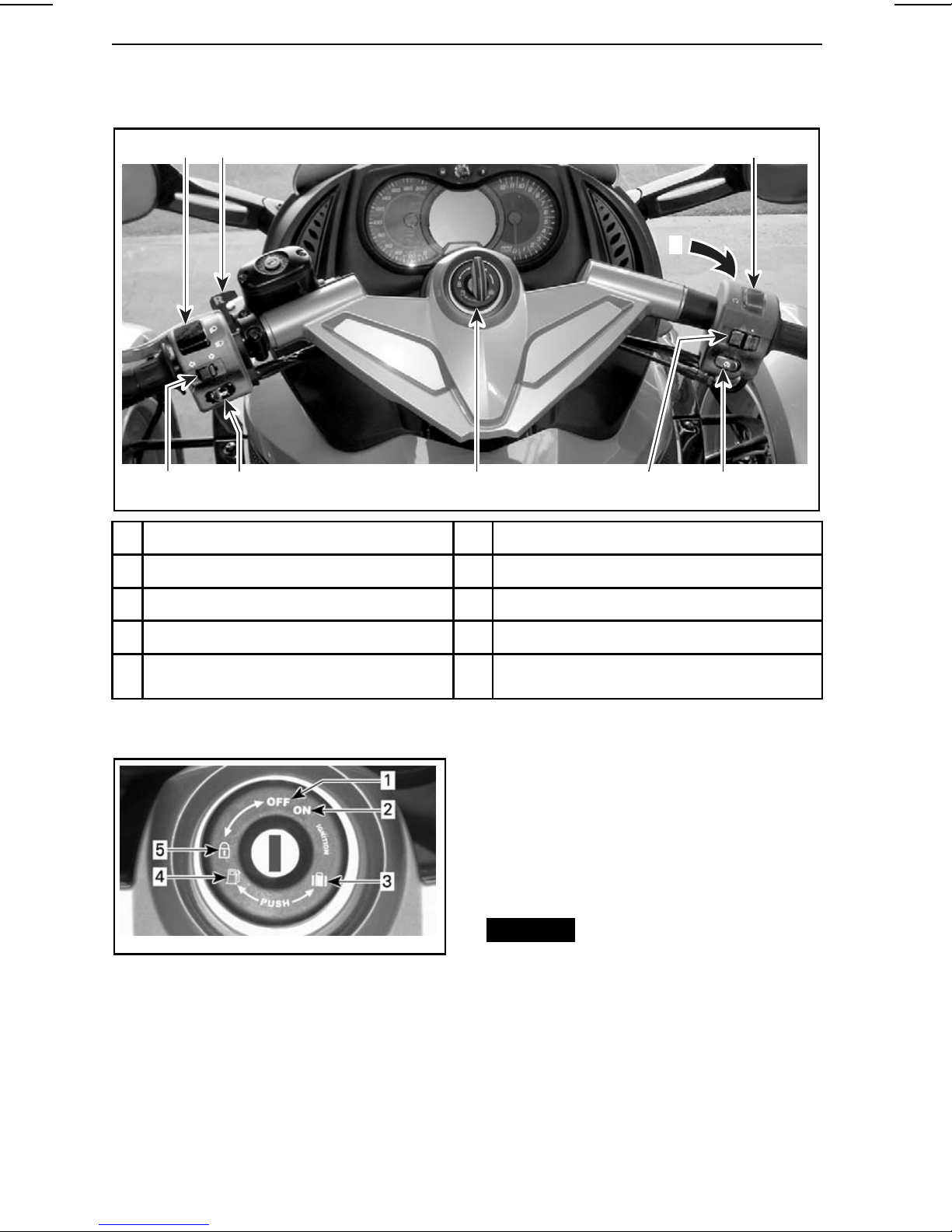
Secondary Controls
85
rmo2008-001-001_a
1
Ignition switch 6 Turn signal button
2 Engine start button
7
Horn button
3
9
4 26 7 1
3 Engine stop switch 8 Reverse interlock lever
4
Hazard warning switch 9 Headlights override button
5
Headlights switch
1) Ignition Switch
– seat opening mec ha nism to access:
• fuel tank cap
• fuses
• brake fl uid reservoirs
• battery terminals.
– front stora ge compartment opening
mechanism
– steering-lock mechanism.
rmo2008-001-002_a
IGNITION SWITCH
1. OFF
2. ON
3. Front storage compartment opening
4. Seat opening/Fuel tank access
5. Steering lock position
NOTICE
easily, do not force it. Pull i t out and
reinsert.
If the key does not turn
The ignition switch is located in the
center of the handlebars . It controls:
– engine ignition
______________________
14
Page 17
CONTROLS/INSTRUMENTS
WARNING
If you turn the ignition switch to
OFF, it shuts off the engine and
all th e elec trical systems including the VSS (p.30), EBD (p.31) and
DPS (p. 31). If you do this while the
vehicle is movi ng, you could lose
control and crash.
NOTE: You should receive two keys
with your vehicle. Each key contains a computer chip spec ifically preprogrammed to start your vehicle.
Store the spare key in a safe place because you must have your spare key
to hav e another one made by an authorized C a n- A m roadster dealer.
2) Engine Start Button
The engine s tart button is near the right
handgrip.
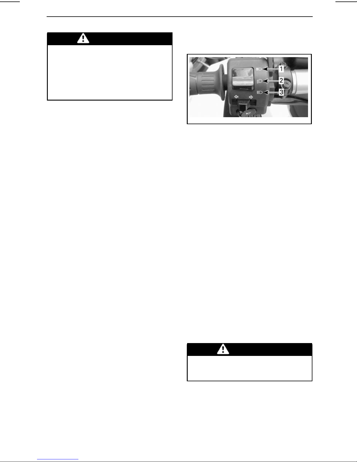
3) Engine Stop Switch
beams w ill stay on as long as you hold
down the switch.
rmo2008-001-061_a
1. High beams
2. Low beams
3. Flash high beams
6) Tu rn Signal Button
The turn signal button is located near
the left handgrip. It turns off automatically after a normal turn, but you may
have to turn it off manually after a shallow turn or l an e chang e.
To turn the signal off, press the button
in.
The engine stop switch is near the
right handgrip. It has two positions and
must be set to the run position before
you can start the engine. It allows you
to stop the e ngine anytime without removing your ha nd from the handlebar.
4) Hazard Warning Switch
The ha zard warning switch is near
the right handgrip. Push the button
to the left to turn on the hazard warning lights.
5) Headlights Switch
The switch is near the left handg
rip,
and is used to select high or low beam
for the headlight. The headlights automatically turn on when the i
gnition
switch is in the ON position.
To select high beams, pus
h the switch
to the front position. To select low
beams, push the sw itc h to the down
position.
To flash the high bea m s, push the
switch down, then re
lease it. The high
Turn signals w ill automatically turn off
after 30 seconds while the ve hicle is
moving.
7) Horn Button
The horn button is loca t ed near the left
handgrip.
8) Reverse Interlock Lever
The reverse interlock lever is located in
front of the left handgrip. Pull it toward
youwithyourrighthandtoallowshifting into reverse. Refer to OPERATING
IN REVERSE (p. 23) for detailed instructions.
WARNING
Do not use the reverse interlock
lever w hile riding forward. You
could lose control.
The hazard warning lights flash when
thevehicleisinreve
rse.
_____________________
15
Page 18
CONTROLS/INSTRUMENTS
9) Headlight Override
There is a headlight override button on
the front of the right handgrip. P us h
and hold the headlight overrid e button
to operate the high beam s . This but-
The button can be used to light up inside the front storage compartment.
The high bea m s will reflect on the
inside of compartment lid w hen it is
opened.
ton will light the high beams even if the
ignition switch is in the OFF position.
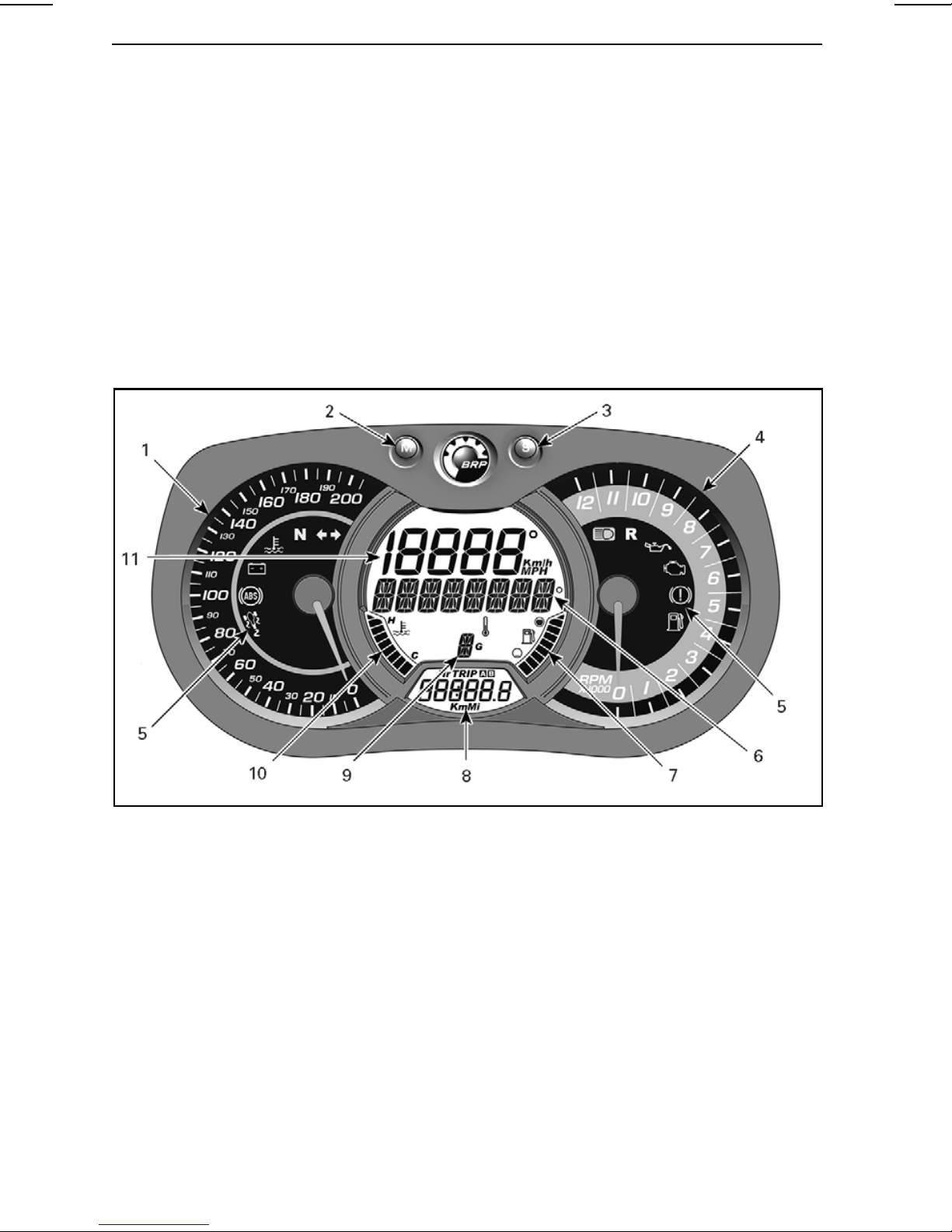
Multifunction Gauge Cluster
The multifunction gauge c lust er includes gauges (speedometer, tacho m eter, engine temperature, fuel level), indicator lamps and a user selectable digital display.
Description
rmo2008-001-050_a
1) Analog Speedometer
Measures vehicle speed in kilometers or miles per hour. To change units, refer to
SETTING METRIC/IMPERIAL UNITS (p.19).
2) MODE (M) Button
Pressing the MODE (M) button w ill scroll through the functions of the s ec onda ry
digital display.
3) SET (S) Button
Pressing the SET (S) button will scroll through the functions of the main digital display.
4) Analog Tachometer (RPM)
Measures engine revolutions per minute (RP M) . Multip ly by 1000 to obta in actual
revolutions.
______________________
16
Page 19
CONTROLS/INSTRUMENTS
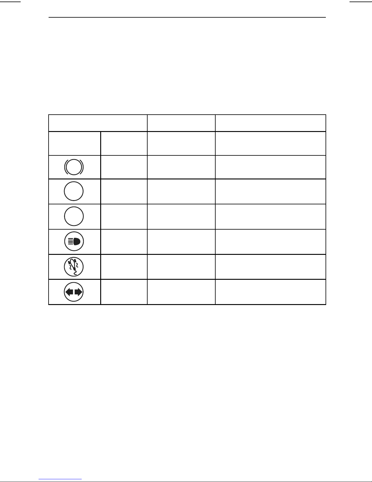
5) Indicator Lamps
Indicator lamps will inform you of various conditions or problems.
An indicator lamp can flash alone or in combination with another lamp.
The digital di splay provides a brief description for some of the conditions or prob-
lems indicated by lamps.
The foll owing table lists the indicator lamps during normal operation. For prob-
lematic conditions, refer to MESSAGES IN M ULTIFUNCTION GAUGE CLUSTER
(p.1 01).
INDICATOR LAMP(S) MAIN DIGITAL
DISPLAY
All indicator
lamps
!
N
R
On
On
On
Flashing None
On None
Flashing None
Flashing None
None
PARK BRAKE Parking brake engaged.
None
DESCRIPTION
All indicator lamps are activated
when ignition switch is set to ON
and the engine is not started.
Gearbox in neutral position.
Gearbox in reverse position.
Headlights in the HIGH beam
position.
VSS intervention occurs.
Turn signal or hazard warning
lights flashing.
6) Main Digital Display
Displays several real time useful informations to the rider.
For display func tio n informations, refer to M AIN DISPLAY FUNCTIONS (p. 18).
Important information messages can also be displayed, refer to MESSAGES IN
MULTIFUNC TION GAU GE CLUST ER (p. 101).
7) Fuel Level
Bar gauge that continuo us ly indicates the amount of fuel left in the fuel tank.
8) Secondary Digital Display
Displays several real time useful information s to the rider. For display function informations, refer to SECONDARY D ISPLAY FUNCTI ONS (p. 18).
9) Gearbox Pos iti ons
Displays the selected gearbox position.
_____________________
17
Page 20
CONTROLS/INSTRUMENTS
The gearbox positions are: R (reverse) , 1, N (neutral), 2, 3, 4, 5.
10) Engine Temp erature
Bar gauge that contin uous ly indicates the engine coolant temperature.
11) Digital Speedometer
In addition of the analo g type speedom eter, vehicle s peed can also be indicated via
this display.
Speed can be displayed in kilometers (Km/h) or miles (MPH) per hour. To change
units, refer to SETTING METRIC/IMPERIAL UNITS (p.19).
Startup and Shutdown
Any time the ignition switch is set to O N after hav ing been in the OFF position for
five minutes or more, the main digital di s play will scroll the following message:
– BEFORE OPERATING READ THE SAFETY CARD ABOVE THEN PRESS _M_
BUTTON.
NOTE: Acknow ledge this message to a llow engine starting.
Digital Display Information
WARNING
Do not adjust the display while riding. You could lose control.
Main Display Functions
Pressing the SET (S) button will scroll through the different functions.
FUNCTION SEQUENCE INFORMATION DISPLAYED
Outside temperature XX C° (Celsius)
XX F° (Fahrenheit)
Tachometer (Revolutions per minutes) XXXX RPM
Secondary Display Functi ons
Pressing the MODE ( M) button will scroll through the different functions.
FUNCTION SEQUENCE INFORMATION DISPLAYED
Clock
Cumulative distance odometer
Trip distance – odometer A (TRIP A) XXXXX.X Km or mi
XX:XX ( 24:00 time base)
XX:XX A or P (12:00 AM/PM time base)
XXXXX.X Km or mi
Trip distance – odometer B (TRIP B) XXXXX.X Km or mi
Trip time chronometer (HrTRIP) XXXXX.X
Engine time chronometer (Hr) XXXXX.X
To reset any trip functions, push and hold the M ODE (M) button for three seconds .
______________________
18
Page 21

CONTROLS/INSTRUMENTS
Display Settings
Setting Metric/Imperial Units
1. Push and hold SET (S) button for three seconds.
2. Main digital displays scrolling message: PUSH _M_ TO SELECT KM, _S_ TO
SELECT MI
3. Push MODE (M) button to s elect metric units or SET (S) button to s elect impe-
rial units.
Setting Clock
1. Press MODE (M) button to select clock display.
2. Push and hold MODE (M) button for three seconds.
3. Press MODE (M) button to s elect 12:00 AM PM or 24:00 time base.
4. If 12:00 AM PM time base selected, A or P flashes.
press MODE (M) button to select A (A M) or P (PM).
5. Press SET (S) button to change hour.
6. Press MODE (M) button to switch to minute (minute flashes).
7. Press SET (S) button to change minute.
8. Press MODE (M ) button.
Setting Language
For display language s etting, refer to an authorized Can-Am roa dst er dealer.
_____________________
19
Page 22
BASIC PROCEDURES
Starting and Stopping the
Engine
Starting the Engine
WARNING
Exhaust gas contains poisonous
carbon monoxi de that can rapidly
accumulate in anenclosedor poorly ventilated area. If inhaled, it can
cause serious injury or death.
Only run the engine in an unenclosed, well ventilated area. See
AVOID CARBON MONOXIDE POISONING (p. 6).
1. Push down and hold the brake pedal.
2. Turn the key to ON.
3. Watch the m ultifunction gauge
cluster. If any indicator lights identify a problem, consult PROBLEMS
(p. 92) be fore ridi ng. The oil light
should be on because the engine
has not been started. Pay attention
to any scrolling messages on the
display.
4. Refer to the Safety Card as needed
to prepare yourself, your pa ss enger and the vehicle, then press the
MODE (M) button to e nable the
starter.
5. Put the engine stop switch in the
RUN/ON position.
6. Pull in and hold the clutch lever
(clutch must be squeezed before
the starter will operate).
7. Shift into NEUTRAL. Check the
multifunction gauge c luster to be
sure you are in neutral.
8. Press and h old the engine start button until the engine s t a rts. Do not
hold the start b utton for more than
15 seconds . If it does not start,
release the button and wait 30 seconds to let the starter cool down
before trying again.
NOTICE
while sta rting the engine.
9. Check the display for problems and
to ensure that the oil light turns off.
10.R elease the parking brake. Make
sure the parking brake indicator on
the multifunction gauge cluster is
off.
NOTICE
fully released before operating the
vehicle, brake pads will drag while
you are moving. This can damage
the b rake system.
Stopping the Engine and Parking
1. Shift the transmission into first
gear.
2. Movetheenginestopswitchto
OFF.
3. Engage the pa r k ing brake. The
brake l oc ks in the depres se d position, and a scr oll ing messag e PARK
BRAKE will appear on the display.
4. Turn the key to OFF.
5. Before dismounting, check that the
parking brake is fully enga ged by
holding the clutch lever in and rocking the vehicle back and forth. As
the brake pads wear, you may need
to push the parking brake lever farther to engage the brak e.
Pushing the Vehicle
CAUTION Avoid pushing the
vehicle on a slope. If you must push
the vehicle on a slope, take extra
care to stay within re ach of the br ak e
pedal in case the vehicle starts to
roll.
To move the vehicle a sho rt distance
without turning on t he engine :
1. While seated on the vehicle, push
down and hold the brake pedal.
Do not apply throttle
If the parking brake is not
______________________
20
Page 23

2. Shift the transmission into NEUTRAL.
3. Disengage the parking brake.
4. Dismount on the right side of the
vehicle, keeping your foot on the
brake pedal.
5. Push the vehicle, using the bra ke a s
needed.
CAUTION Only push from the
right-hand side, so you can reach the
brake p edal. Stay clear of the hot exhaust pipe.
When pulling the vehicle backward,
be careful that the front wheel does
not roll over your feet.
6. Remount the veh icle and park as
specified above.
Adjusting Mirrors
Press the mirror at the points shown
below to adjust its position in the four
directions.
BASIC PROCEDURES
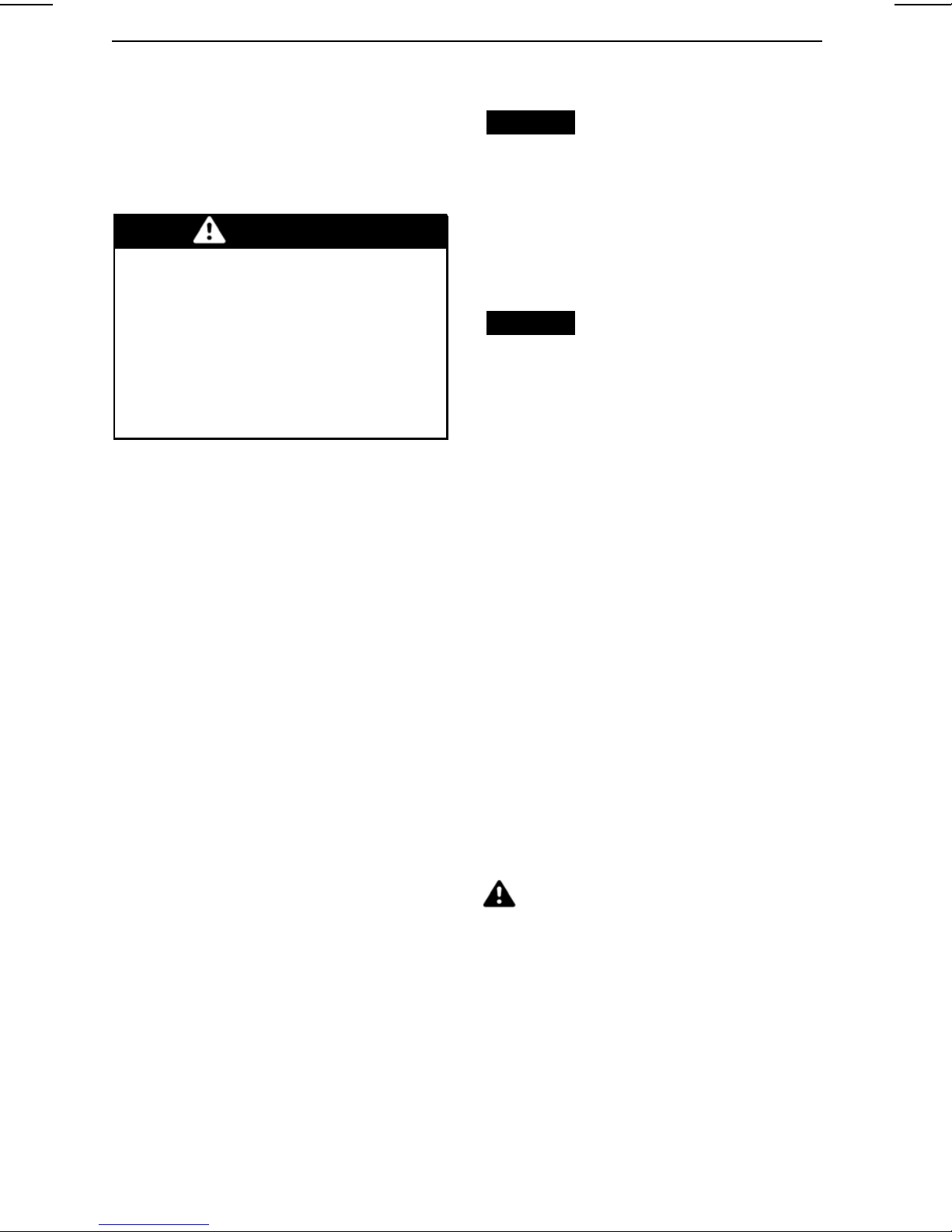
rmo2008-001-074_a
KEY POS ITION TO LOCK HANDLE BARS
1. Turn key 1/4 t urn
Opening the Front Storage
Compa rtment
1. Insert key in ignition switch.
2. Push and turn the key 1/4 turn to
the left to the front storage compartment position and hold while
lifting cover.
rmo2008-001-081_a
MIRROR ADJUSTMENT POINTS
Locking the Handle Bars
Tolockthevehiclebyblockingthe
steering mechanism:
1. Insert key in ignition switch.
2. Rotate the handlebar all the way to
the right or to the left.
3. Turn the key 1/4 turn to the left to
the steering lock position and remove.
rmo2008-001-070_a
KEY POSITION TO OPEN FRONT STORAGE
COM PARTMENT
1. Push key
2. Turn key 1/4 t urn
_____________________
21
Page 24
BASIC PROCEDURES
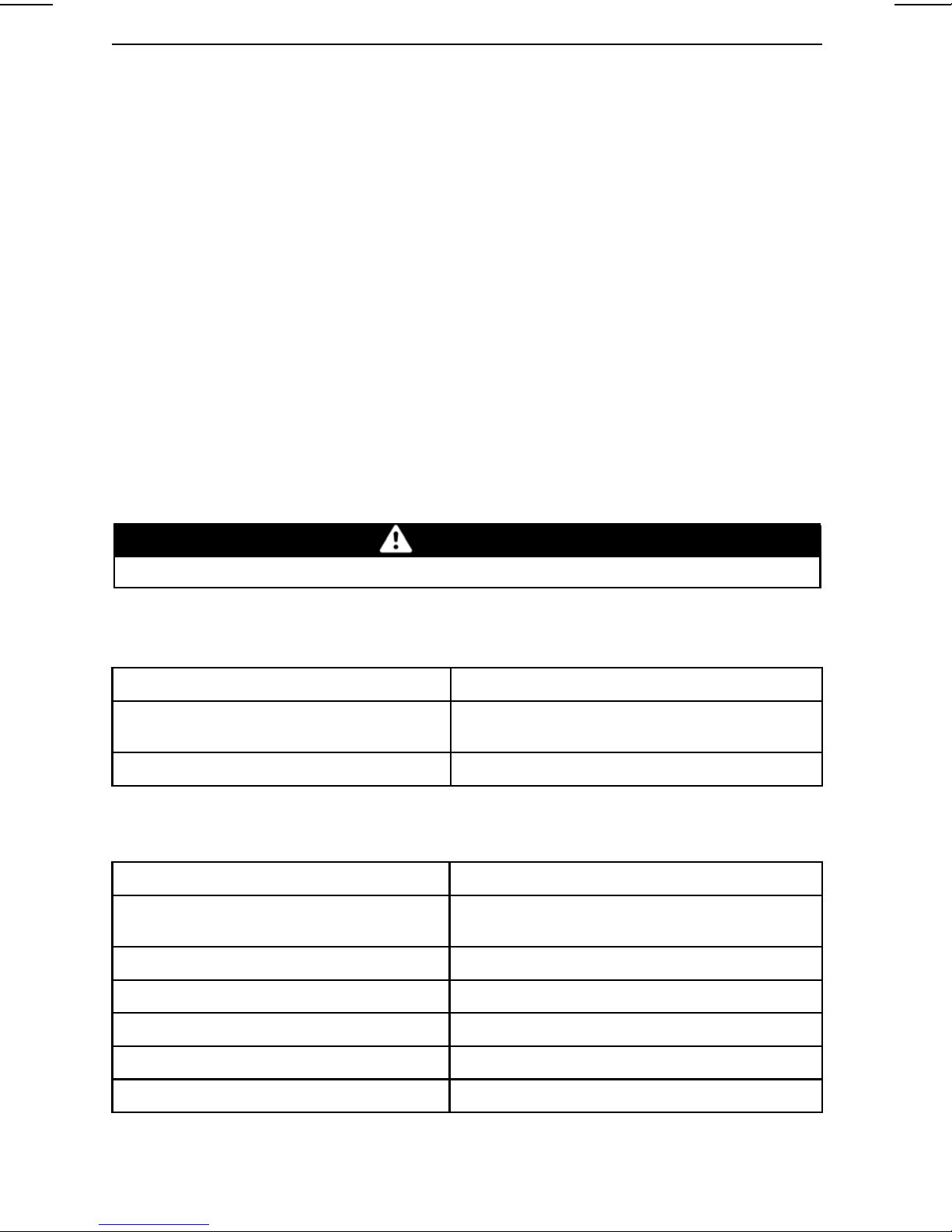
Fueling
Fuel Recommendation
Use unleaded gasoline or oxy genated fuel containin g no more than 10%
ethanol or methanol or both. The gasoline used must have the following min-
imum octane number:
MINIMUM OCTANE NUM BER
rmo2008-001-010
FRONT STORAGE COM PARTMENT
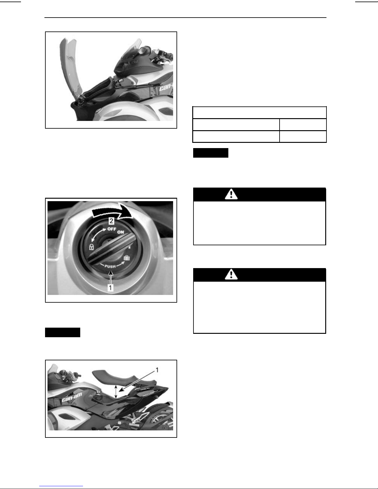
Opening the Seat
1. Insert key in ignition switch.
2. Push and turn the key 1/4 turn to
the right to the seat opening position and hol d while lifting seat.
rmo2008-001-071_a
KEYPOSITIONTOOPENSEAT
1. Push key
2. Turn key 1/4 t urn
NOTICE
the maximum opening angle or it
may break.
Do not force the seat past
Inside North America 87 ((R+M)/2)
Outside North America 92 RON
NOTICE
Other fuel can degrade
vehicle performance and damage
critical p arts in the fuel system and
engine.
WARNING
Do not carry gasoline containers
in the front storage compartment
or anywh ere else on the vehicle.
Gasoline may spill and ignite, particularly in a crash.
Refueling Procedure
WARNING
Gasoline is extremely flammable
and highly ex plos i ve. Follow the
refueling procedure to reduce
the risk of fi re or explosion. See
AVOID GASOLINE FIRES AND
OTHER HAZARDS (p.6).
To refuel the vehicle:
1. Park outdoors in a well ventilated
area away from flames, sparks,
anyone smoking and other sources
of ignition.
rmo2008-001-011_a
1. Maximum opening of seat
______________________
22
2. Stop the engine.
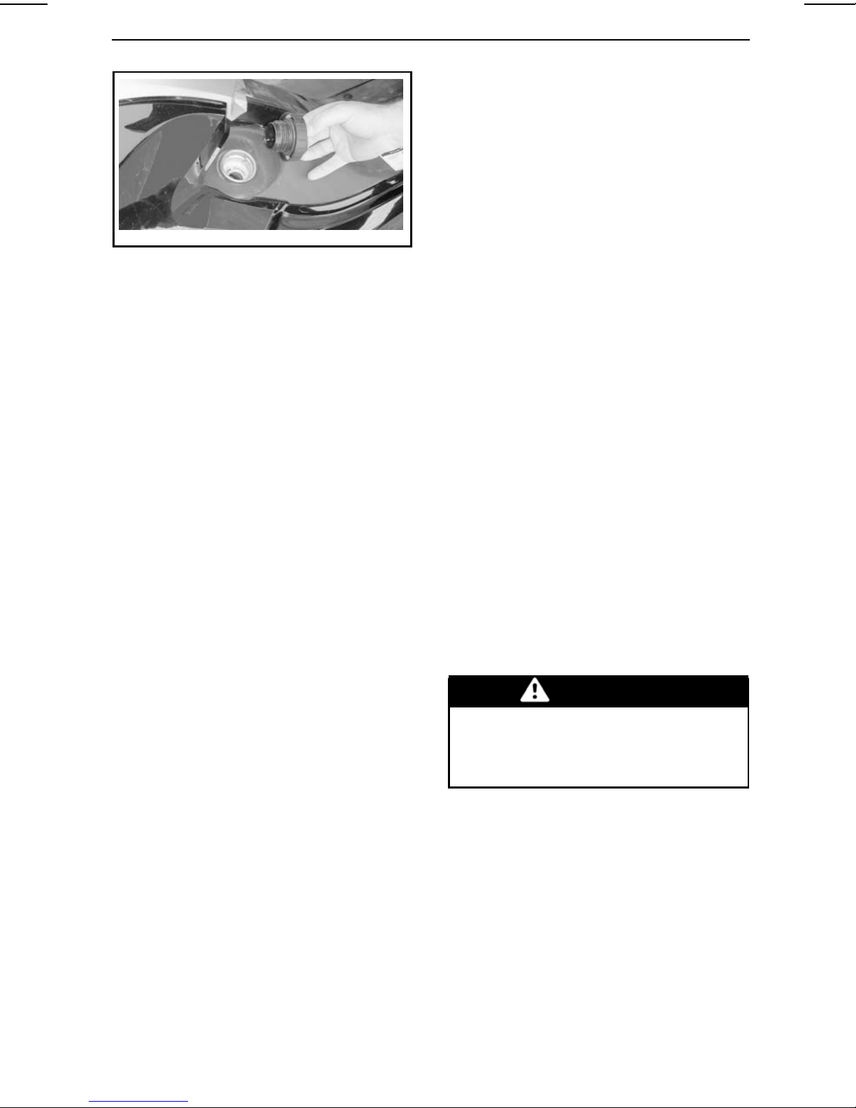
3. Unlatch and lift seat (p.22) . The fu-
el cap is loca ted on the left side.
4. Slowly rotate cap counterclock-
wise and remove it.
Page 25
BASIC PROCEDURES
Operating in Reverse
1. Check that the area behind you is
clear, and continue to look backwards while you ease out the
clutch. Slow and stop using clutch
and brake, just like when operating
normally.
rmo2008-001-016
FUELCAPONLEFTSIDEUNDERNEATH
SEAT
5. Fill the tank until the fuel noz zle a utomatically clicks and shuts off.
Do not try to top off the fuel tank.
Leave some room for the f uel to expand with temperature c ha nges .
6. Wipe up any spilled fuel. If fuel
spills on you, wash with soap and
water and change your c lothes.
7. Put cap on and fully tighten clockwise until you hear a click. Never
start or operate the eng ine with the
fuel cap removed.
8. Close seat.
Operating in Reverse
See REVERSE (p.29) for more informa-
tion about safe operation in reverse.
2. Keep your speed low and do not
back up for long distances.
Shifting Out of Revers e
To shi f t out of reverse, hold in the
clutch and lift the shift lever once to
shift into first. You do not ne ed to use
the reverse interlock lever – it res ets
automatically.
Adjusting Sus pension
The front an d rear suspension can be
adjusted according to the load on the
vehicle or the type of rid e you want to
experience.
Lower spring l oa d provides a softer
ride and is preferred for light loads and
smooth roads. Higher spring load provides a firmer r ide and is recommended for heavy loads, rough road conditions and more challenging riding.
Shifting Into Re verse
1. With engine running, shift into first
gear.
2. Hold in the clutch lever.
3. With y our right hand, pull the reverse interlock lever (ma rked R )
towards you and hold it.
4. Step dow n on the shift lever one
stroke.
5. Release the reverse interlock lever
and check that the letter R flashes
on the m ultifunction ga uge cluster
and the hazard w arning lights flash.
Front Suspension
WARNING
Adjust both springs to the same
load. Uneven adjustment c an
cause poor handling, loss of stability and loss of control.
1. Place the vehicle on a level surface.
2. Engage the parking brake.
3. Adjust the spring preload by turning
the cam with the adjusting w renc h
(stored in the tool kit).
_____________________
23
Page 26

BASIC PROCEDURES
3. Install a jack under the rear portion
of frame.
rmr2008-029-002
FRONT SUSPENSION ADJUSTING WRENCH
rmr2008-029-003
FRONT SUSPENSION CAM ADJUSTMENT
rmr2008-030-004_c
A. Smooth adjustment (position 1 )
B. Hard adjustment (position 5)
RECOMMENDED FRONT SHOCK
ADJUSTMENT
NOTICE
Do not jack the vehicle un-
der the rear shock.
4. Lift the rear of vehicle until the
shock absorber is fully extended.
5. Using XP-S lube (P/N 293 600 016)
or a n equivalent product, lubricate
all around the shock absorber cam.
Lubricate especially near the protrusions.
rmr2008-030-002_a
1. Cam
2. Protrusion
6. With a ratchet and an extens ion,
turn the cam adjuster to change the
position of the shock absorber cam.
LOAD CAM POSITION
68 kg (150 lb) rider 1, 2
91 kg (200 lb) rider 3
68 kg (150 lb) rider
with cargo
91 kg (200 lb) rider
with cargo
Rider with
passenger and
cargo
Rear Suspension
1. Place the vehicle on a level surface.
2. Block the front wheels.
______________________
24
3
rmr2008-030-003_a
4
1. Cam adjuster
2. Ratchet with extension
5
Page 27

BASIC PROCEDURES
rmr2008-030-004_c
A. Smooth adjustment (position 1 )
B. Hard adjustment (position 7)
NOTE: Never adjust the rea r s hoc k
absorber cam from pos ition 7 directly
to position 1 as it will restrain access
to adjustm ent hol es and prevent you
adjusting the suspension.
rmr2008-030-004_d.eps
AVOID ADJUSTING CAM POSITION 7
DIRECTLY TO POSITION 1
A. Po sition 1
B. Po sition 7
rmo2008-002-009
DAMPING PAD (P/N 293 740 028)
Refer to the following procedure for
proper installation.
1. Remove existing pl ate on vehicle (if
applicable).
2. Position n ew damping pa ds over
existing pads on vehicle plate support.
RECOMMENDED REAR SHOCK
ADJUSTMENT
LOAD CAM POSITION
68 kg (150 lb) rider 1, 2
91 kg (200 lb) rider 3 – 5
Rider with
passenger
6, 7
License Plate Installation
When a license plate needs t
stalled or replaced, ensure to install
two new damping pads (P/N 293 740
028) on plate to be ins
talled.
obein-
rmo2008-002-010_a
TYPICAL
1. Existing pads on plate support
3. Peal off backing of new damping
pads.
rmo2008-002-009_a
TYPICAL
1. backing
4. Secure upper portion of lic ens e
plate using existing hardware on
vehicle plate support.
_____________________
25
Page 28

BASIC PROCEDURES
rmo2008-002-010_b
TYPICAL
1. Existin g h ardware
5. Squeeze l icens e plate and support
together at each low er cor ner.
______________________
26
Page 29

T
SAFE OPERATING
INSTRUCTIONS
_________
SAFE OPERATING INSTRUCTIONS
________
27
Page 30

WHAT’S DIFFERENT ABOUT THE SPYDER
ROADSTER
The Spyder roadster is a different ty pe
of road vehicle. This section will help
you understand s om e of the vehicle’s
distinctive features and opera ting characteristics.
Stability
The three-wheeled “Y” config uration
provides greater low-speed stability than a motorcycle. However, it is
not as stable as a four-wheele d vehicle such as an a utom obile. Driving
aid technologies, like the electronic
Vehicle Stabil ity System ( VS S) , help
maintain stability during maneuvers,
but you can still lose control, tip or roll
the vehicle due to extreme maneuvers
(such as hard turns at high speeds) or
striking uneven surfaces or objects.
In addition, the operator or passenger
can fall off due to hard turns, acceleration, braking or impa ct s.
vehicles behind you that ma y not be
able to stop as quickly.
Antilock Braking S ys tem (ABS)
The vehicle is equipped with a n Antilock Braking System (ABS) as part of
the Vehicle Stability System (VSS). For
hard braking, press and hold the brake
pedal. A B S will prevent wheels from
locking.
Parking Bra ke
The parking brake mechanically brakes
the rear wheel only, and it locks in place
when engaged. It is no t c ontrolled by
driving aid technol ogies (e.g., AB S,
Electronic Br ake Distribution). Do not
useittosloworstopthevehicle–you
could lose control, spin, tip or roll over.
Warn p assengers no t to touch it with
their left f oot.
Response to Road
Conditio ns
The Spyde r roadster responds differently than other vehicles to certain
road conditions.
– Do not ride off-road or o n ice or
snow.
– Avoid puddles and running w ater.
The vehicle hydroplanes more easily th an a car. If you must go through
water, s low down.
– Slow down on gravel, dirt or sand
covered roads.
See ROAD CONDITIONS AND HAZ-
ARDS (p. 52).
Brake Pedal
One pedal brakes a ll three wheels.
There is no hand-opera t ed brak e, and
there is no way to brake front and rear
wheels separately. The Spyder roadster is b etter able to brake and steer at
thesametimethanamotorcycle. The
vehicle can stop quickly – be aware of
Steering
Direct Steering
To s teer your Spyder roadster, always
steer in the direction of the turn.
Motorcyclists – D o not countersteer
as i t is done on a motorcycle. Unl ike
a motorcycle, your Spyder roadster
cannot lean while turning. If you are a
motorcyclist, you mu st relearn how to
turn. Practice steering in the direction
of the turn at all speeds until you are
proficient.
Sideways Force s in Turns
Unlike a motorcycle, the Spyder roadster does not lea n in turns. You will
feel sideways forces pushing you to
the outside of the turn. To mai ntain
balance, the operator and passenger
must hold on with both hands an d keep
both feet firmly planted on the footpegs. In hard turns, it may h elp to lean
your upper body forward and toward
the inside of the turn.
________
28
SAFE OPERATING INSTRUCTION S
________
Page 31

WHAT’S DIFFERENT ABOUT THE SPYDER ROADSTER
Width
Because the Spyder roadster is wider
than a typical motorcycle:
– Keep the front wheels in yo ur lane
during turns. Be particularly a w a re
of where your fro nt wheels are in
curves and when passing. If you
take a path that would put a motorcycle’s front wheel near the edge of
the lane, the Spyder roadster’s front
wheel may be out of the lane.
– Don’t share lanes or split lanes
(ride betw een two lanes of traffic).
Group riding should proceed in a single file, even with motorcycles.
– B e prepared to swerve farther to
avoid obstacles.
Reverse
WARNING
– Shift back into first gear before shut-
ting off the engine.
Driver’s License and Local
Laws
Driver’s license requirements for operating the Spyder roadster vary by
location. Depending on local l aws, you
may ne ed a m otorcy cle endorsement,
three-wheeled vehicle endorsement,
or just a standard autom obil e dri ve r’s
license.
Check with local authorities to make
sure y ou have the proper license before operating the v ehicle on public
roads.
Do not engagereversewhileriding
forward. You could lose co ntrol.
The S py der roads ter operates in reverse like a car. However, there are
some important differences:
CAUTION Always k eep both
feet on the p egs while op erati ng in
reverse. Never put your feet on the
ground while backing-up.
– The haza rd warning lights flash
when i t is in reverse, but there are
no backup lights. B e aware tha t other motorists might not know tha t
you are about to back up.
– If nec es sary, have the passenger
dismount if your visibility is limited.
– Remember that the front is wider
than the rear. Don’t back up too
close to objects or you may hit them
with the front tires.
– Keep your speed low a nd do not
back up for long distances.
– When possible, park s o that y ou do
not have to back out o f the parking
space.
_________
SAFE OPERATING INSTRUCTIONS
________
29
Page 32

DRIV ING AID TECHNOLOGIES
VehicleStabilitySystem
(VSS)
The Spyder roadster is equipped w ith
a Vehicle Stability System (VSS). VSS
can help you control the direction of
the v ehicle and reduce the risk of tipping or rolling over in some situations.
VSS consists of:
–anAntilock Braking System (ABS)
that helps maintain steering control
during hard braking by preventing
the wheels from locking.
–aTraction Control System (TCS)
that helps prevent the rear wheel
from slipping. The TCS will limit rear
wheel spin only if you turn the handlebars (steer out of straight line) or
if vehicle speed exceeds 50 km/h
(31 MPH).
–aStability Control System (SCS)
is designed to lim it the pow er driving the rear tire and to brake individual wheel s, which reduc es the r isk
of losing control of the vehicle or
rolling over.
Limitations
VSS cannot help you maintain control
in all situations.
pull off the road during hea vy rain s. If
you must pass through water, slow
down as m uch as poss ible before you
reach it.
Reduce speed on surfaces with poor
traction, like mud, sand, gravel or wet
pavement. The Spyder roads ter is not
for off-road operation. Always operate
the vehicle on maintained roadways.
Do not use the vehicle on any other terrain.
Tire s
The VSS on the vehicle has been calibrated to perform best w ith a tire of
a specific size, m a terial and tread pattern. Replacing your tires with ones
not approved by BRP can cause the
VSStobeineffective.
Use on ly BRP recommended tires,
which can be ordered only from an a uthorized Can-Am roadster dealer.
Proper tire inflation pressure and tread
condition are important for maintaining
traction, especially on loose or wet surfaces.
See TIRES (p. 79).
Hard Turns
Surfaces With Poor Traction
If your tires lose traction w ith the road
surface you may lose control of the vehicle, even with VSS.
Ifthepavedroadsurfaceiscovered
or partially covered with ice, snow
or s lush, there is not enough traction
available to maintain control of the vehicle, even with VSS. Do not operate
on snow, ice or slush.
Like other on- road veh icles, this vehicle can hydroplane on water (lose
traction on a layer of water). If you ride
toofastintoalayerofwater,suchas
a large puddle or flowing water on the
road, the vehicle can lose traction and
spin out, and the VSS c an not keep you
in control. Avoid large water puddles
or water streams, and slow down or
________
30
SAFE OPERATING INSTRUCTION S
The VSS does not control or limit steering input – it cannot keep you from
turning too sharply. Large and rapid
steering handlebar movements can
cause the vehicle to go out of control,
spin, tip or roll over.
Engine Braking
The VSS does not control engine braking (slowing the vehicle by downshifting). If you shift into too low a gear
when you are at high speed , the rear
tire can skid and you can lose control,
spin, tip or roll over, particularly in a
curve.
Excess Speed
The VSS does not control the vehicle’s
speed, except when S CS intervenes
during a turn. VSS does not prev ent
________
Page 33

the vehicle from entering a turn too
fast. If you drive too fast for c onditions, you can l os e control, even with
VSS.
Electroni c B rake
Distribu ti on (EB D)
The Spyder roadster is equipped w ith
an Electronic Brake Distribution (EBD)
system. The EBD system automatically a djusts t he brak e balanc e between
all three wheels. With the ABS, EBD
helps maintain di rectiona l control and
maximize the braking force depending
on the traction available.
The grip of tires on the road surface
limits the maximum bra k ing. Even
with ABS and EBD, your stopping distance will be longer on surfaces with
poor traction or if you do not ma intain
tire pressure and tread condition.
DRIVING AID TECHNOLOGIES
Dynamic Power Steering
(DPS)
The Spyder roadster is equipped w ith
a Dynamic Power Steering (DPS) system, which helps the operator turn the
handlebars.
_________
SAFE OPERATING INSTRUCTIONS
________
31
Page 34

UNDERSTANDING RISK ON THE ROAD
Before you operate the Spyder roa dster, consider your risk of bei ng hurt or
killed in a crash, how you can reduce
the risk and whether you are willing to
take the risk. There are ma ny factors
that contribute to the risk that you face.
You can control some of these factors,
but others , like the behavior of other
drivers, are bey ond your control. Here
are some of the factors that affect your
risk:
Type of Vehicle
Different types of vehicles vary in
terms of size, visibility and m an euverability and provide different degrees of
protection.
The Spyder roadster is small and maneuverable. Maneuverabil ity c a n help
avoid crashes. How ever, smaller vehicles a re harder to see, which increases
the chance tha t other motorists will
cause a crash. In some situations, the
Spyder roadster is less likely to be in
a crash than a m otorcycle. Fo r e xample, you are less likely to tip over at low
speeds while operating the vehicle.
However, in other situations, the vehicle is more likely to be in a crash. For
example, because the vehicle is wider,
it will not fit through as s m all an opening as many motorcycles.
who develop good skills will hav e better co ntrol of their vehicle. Don’t rely
on your experie nc e with motorcycles,
automobiles, ATVs, snowmobiles or
any other kind of vehicle to prepare you
to operate the Spyder roadster. Learn
how this vehicle is different. Read this
Operator’s Guide, watch the safety
video, and if available, take a training
course. Become proficient with the
controlsandbeabletodothepractice
exercises accurately and with confidence before going on the road.
When you begin riding on the road,
start with less challenging situations
(e.g., light traffic, lower speeds , good
weather, no passen ger) and gradually move on to more challe nging riding
situations as you develop your skills.
Plan ahead to avoid situations that are
too difficult for y our skill level, or that
present more risk than you want to
take on.
Even skilled drivers cause crashes.
For example, if you use your skills to
do extreme maneuv ers o r stunts, you
increase your risk. The smart driver
uses good judgment along with skills
to increase the margin of safety a nd
minimize risk. Learn the defensive
driving techniq ues in STREET STRATE-
GIES (p.47).
In cars and trucks, the structure of the
vehicle provides protection in crashes
and from other road hazards. In addition, passengers c a n protect themselves by wearing seat belts. You
should e xp ect that riding the Spyder
roadster is riskier than riding in a car
and t ha t the risk of i njury is more like
riding a motorcycle.
As when riding a motorcycle, you can
reduce the risk of injuries by wearing a
helmet and riding gear.
Operator Skills and
Judgme nt
Every driver has some control over
their own risk on the road. Drivers
________
32
SAFE OPERATING INSTRUCTION S
Rider Conditi on
A d river needs to be alert, sober, and
physically ready to ride. Riding when
intoxicated, tired or otherwise impaired increases the risk of a crash.
Alcohol, d rugs , medications, fatigue,
drowsiness and emotions can a ll i nhibit your ability to ride safely. Like riding
a motorcycle, riding the Spyder roadster is a challenging ac tivity – being in
good physical and mental conditi on
is even more important than for a car.
The safest policy is to nev er operate
the vehicle unless you a r e alert and
completely sober. Even if your blood
alcohol level is not over the legal limit,
________
Page 35

your judgment a nd skills are impaired
by a ny a lcohol consumption.
You must be physically abl e to operate all controls, turn t he h andlebars
through the full rang e of steering,
mount and dismount, and monitor your
surroundings to operate the vehicle.
Passengers also need to be ale rt,
sober and phys ically able to m a intain
their posture, hold on and react appropriately to curves, bumps, acceleration
and stops.
Vehicle Con di tio n
Keep your vehicle in good condition.
Do pre- opera tion checks and perform
regular maintenance. Watch for any
messages on the multifunction gauge
cluster when you start the vehicle, and
address any problems before you ride.
UNDERSTANDING RISK ON THE ROAD
Road and Weather
Conditio ns
Roads with heavy traffic, poor visibility
or poor traction surfaces increase your
risk. Cho ose routes that are appropriate for your s k ill level and the level of
riskyouarewillingtoaccept.
_________
SAFE OPERATING INSTRUCTIONS
________
33
Page 36

RIDING GEAR
Riding three-wheeled, open-air vehicles like the Spyder roadster requires
the same protective gear as motorcycling. Even though the vehicle is more
stable at low speed s t ha n a motorcycle, you can still be thrown off.
This s ec tion is ba s ed on guidance for
motorcyclists given by the Motorc ycle
Safety Foundation (MSF).
In the event of a crash, protective gear
may prevent or reduce injuries. Protective gear also helps y ou stay comfortable and can help provide protection
against the elements.
Recommende d basic protective gear
for riders and passenger includes
sturdy over-the-ankle footwear w ith
non-slip soles, long pa nts , a jacket,
full-fingered gloves and, above all, an
approved helmet with proper eye protection.
1
2
3
4
5
6
rmo2008-001-019_a
RIDING GEAR
1. Approved helmet
2. Eye and face protection
3. Jacket with long sleeves
4. Gloves
5. Long pants
6. Over-the-ankle footwear
Proper apparel can reduce the severity
of injury in case of a cra
sh for both o per-
ators and passengers.
Helmets
Helmets protect the head a nd brain
from inj ury. A helm et can also protect the passenger
’s face from impact
with the back of the op erator’s helmet.
Even the bes t helmet is no guarantee
against injury, but statistics indicate
that helmet use significantly reduces
the risk of brain injury. So, be safe and
always wear a helmet while riding.
Choosing a Helmet
Helmets should be manufactured to
meet the appropriate standa rd in your
state, province or country.
A full-face helmet gives the mos t protection against impacts since it covers
all of the head and face. It can also protect a ga inst debris, stones, insects,
etc.
A three-quarter or open-face helmet
can also offer protection. It is constructed with the same basic components but does n’ t offer the face and
chin protection of full-face helmets.
If you wear an open-face helmet, you
should use a snap-on face shield or a
pair of goggles. Ordinary glasses or
sunglasses are not sufficient eye protection for a motorcyclist. They ca n
shatter or fly off, and they allow wi nd
and a irborne objects to reach the eyes.
Use tinted face shields , goggles or
glasses in the daytime only; do not use
them at night or in poor illuminat ion.
Do not use them if they impair your
ability to discern color.
Other Riding Gear
Footwear
Always wear closed toe footwear.
Sturdy over-the-ankle boots protect
against a variety of riding h azards, such
as stones that get thrown up from the
roadway and burns from the hot exhaust pipe.
Avoid long s hoelaces tha t can be tangled in the gearshift lever, brake pedal
or other parts. R ubber soles and low
heels are a good idea to help keep feet
on the footrests.
________
34
SAFE OPERATING INSTRUCTION S
________
Page 37

RIDING GEAR
Gloves
Full-fingered gloves protect hands
from the wind, s un, heat, col d and
flying objects. Gloves that fit snugly
will improve grip on the handlebars
and help reduce hand fa tigue. Sturdy,
reinforced motorcycle gloves help protect hands in the event of a fall. Gloves
made specifically for motorcyclists
have seams on the outside to prevent
irritation, and are curved to provide a
natural grip when curled around the
handgrips. If gloves are too bulky, it
may be difficult to operate the controls.
Gauntlets keep cold a ir from going up
sleeves and protect the wrists.
rmo2008-001-006_a
1. Glove gauntlet
Jackets, Pants, Riding Suits
Wear a jacket and long pants, or a full
riding suit. Qu ality motorcycle-type
protective gear will provide comfort,
and it can help you avoid being distracted by adverse environmental elements. In case of a crash, good q uality
protective gear made of sturdy ma terial may p rev ent or reduce inj ury. Some
gear includes padding or hard armor
that may further reduce the risk of injury in a crash. P ants also help protect
against burns from hot pa rts.
Protective gear sold for m otorcycling
will often prov ide the best c om bination
of fit and protection. These garm ents
are designed to fit while sitting in a riding position. They a re cut longer in the
sleeves and legs and are fuller across
the shoulders. Riding suits are available in both one-piece and tw o-piece
sets.
Leather is a good choice becaus e it is
durable and wind-resistant and provides protection a ga inst injury. Other abrasive-resistant protective gear
made of synthetic fabrics are good
choices, too. Do not wear loose or
long clothing or scarves that can become tangled in the moving parts.
Flaps and fasteners seal out the wind.
A jacket with a zippered front will be
more wind resistant than a jacket with
buttons or snaps. A flap of material
over the zipper of a jac ke t gives additional protection against the w ind.
Jackets with snug cuffs and w aist
are recommended to keep wind from
blowing in. A large, loose collar can
flap when riding and may irritate skin or
be a distraction.
In c ool-weather riding, protect yourself against hypothermia. Hypothermia, a condition of low body temperature, can cause loss of concentration,
slowed react ions and loss of smooth,
precise muscle movement. In c ool
conditions, pro per protec tive gear like
a wi ndproof jacket and insulated layers
of clothing are essential. Even at moderate temperatures, you can feel very
cold due to the wind while riding.
Protective gear that is ap propriate for
cold-weather ridi ng may b e too hot
when stopped. Dress in layers so that
clothing can be removed as desired.
Topping the protective gear with a
windproof outer layer can prevent cold
air from reaching the skin.
Riding gear can also help a rider be
more visible. Wearing bright c olors is
a wise choice. If a dark jacket is worn,
an inexpens ive reflective vest can be
worn over it. It is a good idea to put
extra reflective tape on garments worn
regularly while riding.
Rain Gear
If you mus t ride in wet weather, a rain
suit or a waterproof riding suit is r ec ommended. On long rides, it is a good
idea to carry rain gear. A dry rider will
_________
SAFE OPERATING INSTRUCTIONS
________
35
Page 38

RIDING G EAR
be much more comfortable and alert
than a rider who is wet and cold.
One- or two-piece styles are available,
and those designed specifically for
motorcycling are best. High-visibility
orange or yellow colors are good choices. A feature to look for is elastic in
the waist, pant legs and sleeves. The
jacket should have a high collar a nd zip
up with wide flaps across the opening. When purchasing a rain suit, consider adding waterproof gloves a nd
footwear.
Remember, if the weather is wet, it is
best to a v oid riding. If y ou do ride in
wet weather, you may nee d to s top if
water starts to accumulate on the r oad.
Hearing Protec tion
Long-term exposure to wi nd and motor n oise when riding can cause permanent he aring loss. Properly worn
hearing protective devices such as
earplugs can help prevent hearing loss.
Check local laws before using any hea ring protective devices.
________
36
SAFE OPERATING INSTRUCTION S
________
Page 39

REQUIRED RIDING SKILLS AND PRACTICE
EXERCISES
Before you take the Spyder roadster
on the road, you need to develop riding skills and strategies for managing
risk on the road. The following exercises w ill familiarize you with the basic
operation of the vehicle. If you ha v e
experience with m otorc ycles or other
motor vehicles, pay particular attention
to how the S py der roa dst er’ s operation
and performance are different from vehicles you are used to. Practice each
exercise until you can perform it proficiently before moving o n to the next.
This section includes the following exercises:
1. Revving the engine and using the
engine stop switch (p.38)
2. Learning the friction zone and ba-
sic handling (p.38)
3. Engine stop while in motion (p.39)
4. Using the throttle (p.40)
5. Basic turns ( p. 40)
6. Quick stops (p.41)
7. Weaves (p.42)
8. Shifting (p.43)
9. Swerve (p.45)
10. Operating in reverse (p.45).
Keep this basic parking lot diagram in
mind when setting up the exercises.
3m(10ft)wideparkinglotspacesare
indicated in the diagrams for convenience, but the size of the spaces in
thelotyouusemaybedifferent. Ifthe
parking l ot you choose doesn’t ha v e
lines or if the parking spaces are sized
much larger or smaller tha n the ones
in the diagrams, use the dimensions
shown below. Mark them using a ta pe
measure and c ha lk or markers such
as cones or m ilk containers weighted
with water or sand.
1
5
3
4
2
5
5
ChoosingaPracticeArea
Perform the se exercises i n a paved
area at least 76 m by 30 m (250 ft by
100 ft) that is not open to traffic. A
closed, well marked parking lot without obstacles (light poles, curbs, etc.)
makes a good practice area. Be aw are
of oil left by parked cars. Look for parking lots that are empty during off hours,
such as at schools, churches, community centers or shopping centers. Do
not trespass on pri vate property.
Once you’ve selected a suitable location, get permission to use it from the
owner. If there are obstructions, such
as light pole s or islands, be sure that
they don’t interfere w ith the r equired
open pa ths sh own in the diagram below.
_________
SAFE OPERATING INSTRUCTIONS
5
rmo2008-001-046_o
TYPICAL PARKING L OT
1. At least 30 m (100 ft)
2. At least 75 m (250 ft)
3. 12 m (40 ft)
4. 6m(20ft)
5. Open area
Even in a closed lot, be aware of potential traffic.
Check to the front, sides
________
37
Page 40

REQUIRED RIDIN G SKILLS AND PRAC TICE EXER CISES
and rear before doing an exercise. Also, watch out for children and animals.
Preparing to Ride
Know the location and opera t ion o f all
the vehicle’s c ontrols (p.11).
Perform the pre-ride inspection (see
p.66) before beginning.
Always start and stop the engine according to the instructions on p.2 0.
Riding Post ure
Good posture helps you m a neuv er the
vehicle more easily. Always keep b oth
hands and both feet in position so that
you ca n operate the controls easily.
The wrist should typically be aligned
straight with the arm (this position
helps you apply the amount of throttle you want). Arms sh ould be relaxed
and bent. Keep y our back straight and
your head and eyes up. Kee p both feet
on the pegs n ea r the controls.
Never operate the vehicle, even for a
short distance, unless you are in the
proper riding posture.
– Become familiar with using the en-
gine stop switch.
Directions
– WiththevehicleinNEUTRALand
the parking brake engage d, pull in
and hold the clutch lever. Watch the
tachometer and rol l on the throttle
(twist it toward you) a few times
toraisetheRPMtonomorethan
4 000. As long as the clutch is fully
pulled in, the powe r will not tra ns fer
to the rear wheel.
– Use the engine st op switch to cut
all pow er to the vehicle. Press the
switch with your right thumb while
keeping your hand on the handgrip.
Tips for additional practice
– Practice pressing the en gine stop
switch without looking at it.
2) Learning the Fricti on Zone and
Basic Handling
Pulling in the clutch disengages power
to the rear wheel – if you feel like you
are losing control while doing these
exercises, you can pull in the clutch to
stop accelerating and apply the brake
as needed to slow down. You can also
use the engine stop switch to cut power entirely.
rmo2008-001-062
RIDING POSTUR E
Practice Exercises
1) Revving the engine and using the
engine stop switch
Purpose
– Become familiar with the sound of
theengine revving soyou will not be
surprised during th
________
38
eexercises.
SAFE OPERATING INSTRUCTION S
The friction zone is the area in the travel o f the clutch lever that begins wh ere
the clutch starts to transmit power to
the rear wheel and ends just be fore the
clutch becomes fully engaged. While
the clutch is partially en ga ged, it allows
you to precisely control engine power
transmitted to the rear wheel. Proper
use o f the friction zone helps you get
moving smoothly from a s t op.
Purpose
– Become familiar with the clutch and
operating within the friction zone.
– Become familiar with low speed de-
celeration and braking.
________
Page 41

REQUIRED RIDING SKILLS A ND PRACTICE EXE RCISES
Directions
For this ex erc ise, do NOT use any
throttle. You will be controlling your
movement using only the clutc h i n the
frictionzoneandbrake.
Begin by stopping every 6 m (20 feet)
(every marker/every second line).
– Start the engine and release the
parking brake.
– With the brake pedal depres s ed and
the clutch l ev er pulled in, sh ift the
transmission into first gear by firmly
pushing down on the shi ft lever.
– Release the foot brake.
– Slow ly let out the clutch lever until
the vehicle starts to creep forward.
Hold the clutch lever at thi s point.
This is the friction zone. If you r e-
lease the clutch too quickly, the en-
gine m a y s tall or the vehicle may
jump forward. Ifthevehiclestalls,
restart the engine and try again, re-
leasing the clutch more gradually.
– As you approach the stopping point,
pull the clutch lever all the way in
and press the brake pedal to stop.
Pulling the clutch in does not ha v e
to be gradual – you can do this quick-
ly.
– When you reach the end of the
straightaway, stop, turn the han-
dlebar all the way to the right, and
turn around. Be car eful not to roll
the throttle a s you turn. Stop when
you are in line with the straightaway
in the oppos ite direction.
– Repeat this exerc ise until you feel
comfortable.
3) Engine Stop while in Motion
Purpose
– Become familiar with using the en-
gine stop switch when in motion so
you know how the vehicle will react
if you n eed to use it later.
Directions
– Partw ay do wn the straightaway,
while operating in t he friction zone,
turn the engine stop switch to OFF
and coast to a stop.
– Restart the engine and repeat the
exercise. Try releasing the clutch
farther and m ov ing a little faster before using the engine stop switch.
– Restart the engine and proceed to
the next exercise.
3
4
2
5
1
Tips for additional practice
– As you become more comfortable
with the friction zone, try s topping
every 12 m (40 ft) (every other cone)
so that you can fully release the
clutch.
_________
SAFE OPERATING INSTRUCTIONS
rmo2008-001-046_c
1. Start
2. Press engine stop switch
3. Proceed to end of straightaway, stop and
turn as before
4. Stop
5. Press engine stop switch
________
39
Page 42

REQUIRED RIDIN G SKILLS AND PRAC TICE EXER CISES
4) Using the Throttle
Purpose
– Become familiar with operating the
throttle.
– Learn to balance throttle and cl utch .
Directions
This exercise is similar to the friction
zone exercise, except thi s time you
will be usin g some throttle. You will
use the entire straightaway, stopping
only at the ends.
– Start this exercise stoppe d in first
gear at the beginning of a straightaway.
– With the c lutch lev er pulled in,
gently roll on the throttle until the
tachometer reads betw een 1 500
and 2 000 RPM. Practice holding it
within this ra nge.
– Hold the throttle at this position
while gently rel ea sing the clutch
lever as before. Try not to let the
RPMs exceed 2 500.
– The more quickly you release the
clutch lever, the more quickly you
will accelerate. If you release the
clutch too quickly, the engine may
stall or the vehicle may jump forward.
Applying too m uc h throttle can
cause the rear wheel to spin and
can result in rapid acceleration.
– When the clutch lev er is fully re-
leased, the throttle c ontrols your
speed.
– As you approach the end of the
straightaway, roll off the throttle,
pull in the clutch lever a nd apply the
brakes to come to a stop.
– Without u sing throttle, turn around
and head down the opposite
straightaway.
3
2
1
rmo2008-001-046_d
1. Start
2. Roll off throttle
3. Stop
4. Roll off throttle
3
4
3
Tips for additional practice
– Coordinate releasing the clutch
lever and applying the throttle to
start smoothly and to control your
acceleration.
– Once you have mastered starting
on a flat surface, practice starting up
an incline. To do this, keep holding
the bra k e pedal a s y ou release the
clutch lever until you are in the friction zone. This will keep you from
rolling backwards.
5) Basic Turns
Purpose
– Get comfortable turning in a con-
trolled manner.
Directions
________
40
SAFE OPERATING INSTRUCTION S
Riding through turns and curv es with
your Spyder roadster is different than
on a motorcycle. The vehicle does not
lean in a turn, so you may need to shift
your body weight to the inside of t he
turn to keep a comfortable posture
________
Page 43

REQUIRED RIDING SKILLS A ND PRACTICE EXE RCISES
on the v ehicle. You will need to exert
more force to turn the handlebar of
your vehicle than is needed to turn a
motorcycle. However, it is easier to
stop while turning than with a motorcycle.
This exercise is similar to what you
did before, except tha t now instead of
stopping for ea ch turn, you will make
the turn in the friction zone.
– Proceed down the straight away in
first gear.
– As you approa c h the curve, slow
downtonomorethan8km/h
(5 MPH) by pulling in the clutch lever
and apply brake if needed.
– Hold the clu tch lever in the friction
zone to ma intain your low speed.
– Look in the direction of the curve.
– Turn the handlebar in the direction of
the curve, pulling on the inside hand-
grip and pushing on the outside, be-
ing careful not to roll on the throttle.
– It might be helpful to lean forward
and into the curve. This m a y hel p
you turn the handle bars more eas i-
ly.
– Straighten your handlebar after the
turn and p roce ed dow n the straight-
away.
3
2
2
1
3
rmo2008-001-046_e
1. Start
2. Friction zone
3. Apex
Tips for additional practice
– After you are comfortable turning i n
one direction, try going around the
course the other way. Be careful
not to app ly more throttle than you
intend when turning left.
– Stop at the apex of the turn to see
what it’s like to use your brakes in a
curve or turn.
rmo2008-001-064
RIDING POSTURE WHEN TURNING
_________
SAFE OPERATING INSTRUCTIONS
6) Quick Stops
Purpose
– Become familiar with the vehicle’s
braking ability.
– Learn to apply brakes with maxi-
mum force.
Directions
This exercise is similar to what you
did befo re, except you’ ll be applying
the brake more firmly, w orking up to
braking a s hard as possible. The Antilock Braking System (ABS) will prevent the w heels from locking and help
________
41
Page 44

REQUIRED RIDIN G SKILLS AND PRAC TICE EXER CISES
you maintain steering control w hil e applying the maximum braking force.
– Start at one end of the straight away
and accelerate to 8 km/ h (5 MP H).
Partway down the straightaway,
brake quickly. Do not pump the
brakes – the ABS will prevent wheel
lock.
– Keep head and eyes up, k eep ha n-
dlebars s tra ight, a nd do not release
the brake unti l fully stopped.
– Repeat, increas ing your speed and
braking harder.
1
Directions
6m(20ft)Weave
– Weave between every m a rker/
intersection of every other parking spot. Do not use throttle – sta y
in the friction zone. Le an into each
turn and turn the handlebars in the
direction you w a nt to go by pulling
and pushing the grips.
2
2
rmo2008-001-046_f
1. Start
2. Stop
Tips for additional practice
– Practice checking your mirrors be-
fore braking hard.
7) Weaves
Purpose
– Get more experience with the vehi-
cle’s handling and ride r position.
1
rmo2008-001-046_j
NO THROTTLE
1. Start
12 m (40 ft) Weave
Once you’re comfo rtable, try doing
12 m (40 ft) weaves between every
other cone/every fourth park ing space.
________
42
SAFE OPERATING INSTRUCTION S
________
Page 45

1
rmo2008-001-046_k
NO THROTTLE
1. Start
Tips for additional practice
– You can gradually increase speed as
you get comfortable to 16-19 km/ h
(10-12 MPH) for the weaves, but
slow down for the U-turns at the
ends.
8) Shifting
When riding, you must change gears
to m a tch the engine speed with road
speed. Lower gears are used for lower s peeds and higher gears are used
for higher speeds, just like on a ma nual transmission car or truc k. Shift up
soon enough to avoid overrevving the
engine (RPM abov e the engine red
line, audible increase in engine speed),
but not so soon as to cause the engine
tolug(theenginewillfeelandsound
rough and you may feel vibration i f it
lugs).
REQUIRED RIDING SKILLS A ND PRACTICE EXE RCISES
Purpose
– Become familiar with the foot mo-
tions needed to s hift gears.
– Learn to upshi ft and downshift.
Directions
This exercise is similar to wh at y ou di d
before, ex cept now you will be upshifting on the straightaways, then coming
to a stop at the e nd of each straightaway. You may want to use the parking
lot aisles for this exercise rather than
riding in the spaces.
8a) Practice Using the Shift Lever at
aStop
First, while stoppe d, practice the left
foot motion for shifting between first
and second gears.
– At a stop in first gear, pull in the
clutch lever.
– Slide the tip of your le ft foot under
theshiftleverandliftitasfarasit
will go, one firm stroke up to shift
into second gear.
– Step on the shift lever and press it as
far as it will go, one firm stroke down
to shift into first gear.
– Repeat until you are comfortable
with the foot motions required.
8b) Upshifting from First into
Second Gear
– In the straightaway, accelerate to
approximately 16 km/h (10 MPH) in
first gear.
– To upshift:
• Roll off the throttle.
• Pull in the clutch leve r. (If you
pull in the clutch before releasing
throttle, the engine may rev – just
release the throttle if this happens.)
• Slide the tip of your left foot under
the shift lever and lift it as far as it
will go, one firm stroke up to shift
into second gear.
• Smoothly ease out the clutch.
_________
SAFE OPERATING INSTRUCTIONS
________
43
Page 46

REQUIRED RIDIN G SKILLS AND PRAC TICE EXER CISES
• You do not need to apply throttle,
but once you are comfortable, if
space allows, you can adjust the
throttle to increas e speed in second gear.
• Put your foot back on the peg.
– As you approach the end of the
straightaway, come to a stop:
• Roll off the throttle.
• Pull the clutch lever all the way in.
• Apply brake.
• After stoppi ng, downshift i nto
first gear by stepping on the shift
lever and pressing it as far as it
will go, one firm stroke dow n.
Once you are more comfortable,
downshift into first as you com e
to a stop.
3 3
2
2
1
rmo2008-001-046_h
1. Start
2. Shiftintosecondat16km/h(10MPH)
3. Stop
3
8c)IfSpaceAllows,Practice
Downshifting into First Wh ile
Moving
– In the straightaway, slow to approxi-
mately 16 km/h (10 MPH).
– Roll off the throttle and pull in the
clutch lever.
– Step on t he shift lever to shift into
first gear.
– Smoothly ease out the clu tch.
– Put your foot bac k on the peg.
8d) Other Gears
If space allows, you can try shifting into
and out of higher gears as well. Fol low
the same process and shift up or down
one gear at a time.
Tips for additional practice
As you gain more experience, you can
refine your shifting skills and use them
to better control the vehicle.
– When downshifting, rolling on the
throttle slightly while smoothly eas-
ing out the clutch can help the en-
gine rev up to match vehicle spe ed
more quickly and ma k e the down-
shift smo other, preventing skidding
of the rear w heel.
– Shifting to a lower gear causes an
effect similar to using the brakes.
This i s known as engine brak ing.
To use engine bra k ing, shift down
one gear at a time a nd ease out the
clutch between eac h downshift.
Keep the clutch in t he friction zone
until the engine speed stabilizes,
then ease out the lever fully until
ready for the next downshift.
– Usually you shift gears on e at a time,
but it is possible to shift through
more than one gear while the clutch
is squ eezed by repeating the up or
down stroke as many times as you
want gear changes.
Remember tha t VSS does not co ntrol
engine braking. If you shift into too low
a gear when you are at high speed, the
rear tire can skid and you can lose control, spin out, tip or roll over, particularly
in a curve.
________
44
SAFE OPERATING INSTRUCTION S
________
Page 47

REQUIRED RIDING SKILLS A ND PRACTICE EXE RCISES
9) Swerve
Purpose
– Become familiar with the vehicle’s
handling for quick maneuvers.
– Try different variations of braki ng
and swerving.
Directions
At this point you w ill need to change
your course. Set up your markers as
shown in the diagram below. Do not
use any fixed or hard, heavy objects as
markers for this exercise.
– Enter b etween the double cones at
about 8 km/h (5 MPH) and m a intain
that s peed throughout.
– Steer around the line of cones.
– Exit throu gh the second set of dou-
ble cones.
2
10) Operating in Reverse
Purpose
– Become familiar with the vehicle’s
handling and turning radius in reverse.
Directions
– Shi ft into reverse. Se e OPERATING
IN REVERSE (p. 23).
– Check that the area behind you is
clear, and continue to look backwards while you ease out th e clutch.
Be ca r eful not to strike anything
with your front wheels as you back
up. Slow and stop using clutch and
brake, just like when operating normally.
– Back for a few feet at time, stoppi ng
in between.
– Keep your speed low a nd do not
back up for long distances.
– A fter you are comfortable with re-
verse, back into a parking space as
shown in t he di agram below.
1
3
1
2
rmo2008-001-049_a
1. 6m(20ft)
2. 3m(10ft)
3. 2.5 m (8 ft)
Tips for additional practice
– You can gradually increase y our en-
try spee d (to no more than 13 to
19 km/h (8 to 12 MPH)) and try some
variations. For example, approach
faster and slow before entering the
exercise, pull in the clutch and apply
brakes during the swerve , etc.
– Practice checking your mirrors and
blind s pot before y ou swerve.
4
3
2
1
rmo2008-001-048_a
1. Start
2. Reverse
3. Stop
4. Forwar d
Developing Advanced
Riding Skills
Once you have mastered basic riding
skills, you can begin developing more
_________
SAFE OPERATING INSTRUCTIONS
________
45
Page 48

REQUIRED RIDIN G SKILLS AND PRAC TICE EXER CISES
advanced skills. First, learn the ”Street
Strategies” c ov ered in the next section. Then you can take the vehicle
on the road in relative ly low -risk situations.
Start by riding in less challenging situations:
– short distances
– good weather
– low traffic
– daytime
– lower speeds
– no passenger.
You can gradually move on to more
challenging riding situations as you develop your skills.
________
46
SAFE OPERATING INSTRUCTION S
________
Page 49

STREET STRATEGIES
This section provides som e strategies
to reduce your risk on the road . Ma ny
of these strategies are similar to those
used for motorcycles.
This s ec tion is ba s ed on guidance for
motorcyclists given by the Motorcycle Safety Fo unda tion (MSF). Ho wever, even experienced motorcyc lists
should read this section, as som e
strategies are different for the Spyder
roadster.
Plan Your Trip
Always check weather c onditions before riding the vehicle. Take appropriate gear for a ny weather you might
encounter.
Plan a route and ride in c onditi ons that
are appropriate for your skill level.
Thevehiclehasa25L(6.6U.S.gal)fuel
tank. When the low fuel indicator li ght
flashes, fill fuel tank as soon as possible. Plan your refueling stops, particularly in unpopulated areas.
Defensive Riding
As with a m otorc y cle, defensive riding
can help y ou a void crashes. You need
to stay alert at a ll times. Never stop
watching your su rroundings, including the area behind you. Always scan
for pot ential hazards, plan ahead, and
leave space and time to avoid trouble.
Do not assume other motorists will
see y ou or follow the rules of the road.
braking distance is longer on slippery
road surfaces, down hills, or w hen carrying more weight, and visibility may
be limited in fog, in curves or at night.
Scanning Ahead
In a dditio n to leaving a dequate following distance to the next vehicle, scan
ahead and plan your path even farther
in advance.
Plan your immediat e path at least four
seconds ahead. Watch this path for
hazards, such as anything in the road
or any t hing entering t he road.
Scan ahead 12 seconds along y our anticipated path to identify potential hazardous situations before they happen.
For example, look for intersections
where other vehicles may a ppea r or
places where pedestrians might enter
the road. Be prepared to respond if a
hazardous situation develops.
Watch Behind and to the Sides
Vehicles and oth er ha zards can approach from a ll directions. Cons ta ntly
be aware of your surroundings. Check
your m irrors frequently to s ee directly behind yo u. A lso do frequent head
checks (turn your head to look) to monitor your blind spot.
A A
Following Distance
Always leave at least a two–second
following distance between you and
the vehicle in front of you whe n operating under ideal riding conditions. This
means that you should pass any fixed
point on the road at least two f ull seconds after the vehicle in front of you.
When condition s make braking distance longer, or visibility is limited,
use a longer following distance for a
greater margin of safety. For example,
_________
SAFE OPERATING INSTRUCTIONS
rmo2008-001-014_a
A. Operator’s blind spots
________
47
Page 50

STREET STRATEGIES
When braking, be particularly aware of
vehicles behind you that ma y not be
able to stop as quickl y a s the S py der
roadster.
Keep Your Eyes Moving
To stay aware of your surroundings, do
not fixat e on any one thing. Move y our
eyes cons tantly to moni tor the road,
traffic control markings and devices
and other vehicles. L ook near and far,
in all directions.
Anticipate Trouble
Whenever yo u notice a potential hazard, plan a way to a vo id it. This might
mean adjusting your speed or lane position, or changing lanes. You should
be ready for evasive maneuvers such
as swerving and/or braking if something enters your path. Always leave
time and space to react to trouble.
Being Visible
Motorists tend not to see smaller vehicles l ike motorcycles. Therefore you
should use strategies to become more
visible.
signals, but they ma y not cancel after
shallow turns. Make sure turn signals
are off after you have completed your
maneuver; leaving them on may confuse other motorists.
When possible, fl ash your brake lights
before slowing and when waiting at
intersections, to alert motori sts behind
you.
Use your emergency flashers to make
yourself visible when needed.
You can also use your horn to attempt
to alert other motori sts of your presence.
Do not assume that other motorists
will notice yo ur lights, signals or horn.
Blind Spots
Avoid ri ding in the blind spots of other v ehicles. Position yourself so tha t
drivers ahea d can see you in their mirrors. In some cases, such as when you
are follow ing a truck or a bus, you must
be farther behind the vehicle in front of
you.
To be More Visible to Other
Motorists
Lighting and Reflectors
Make s ure that the headl ights, running lights and tail lights on your vehicle work properly. Your vehicle is
equipped with reflectors on the fenders, sides, and back. Make sure that all
reflectors are cle an and not broken or
missing.
Use you r high bea m s when ev er possible, both day and night. Use low
beams to avoid blinding other motorists at night or w hen too much light
reflects back, such as in fog.
Signals
Use your turn s ignals to inform others of your intentions. The Spyder
roadster has automatic canceling turn
A A
rmo2008-001-015_a
A. Blind spots of other vehicles
________
48
SAFE OPERATING INSTRUCTION S
________
Page 51

STREET STRATEGIES
Time of Day and Weather
In dim light, such as at night, at dawn
or dusk , or in poor wea ther such a s rain
or fog, you may be harder to see. Glare
at dawn and dusk or very bright sunlight can a lso make it ha rder for other
motorists to see you.
Clothing
Bright colors or reflective c lothing can
increase your visibility.
Be Careful Even When Motorists
See You
Even when m otorists s eem to notice
you, they ma y still drive in a w ay that
puts you at risk of a crash. Drive defensively, and don’t rely on other motorists to operate their vehicles safely.
Lane Po sition
for drivers ahead to see you , you m ust
be able to see their mirrors. When you
are being followed by a large vehicle,
passing vehicles may not be able to
seeyoueasilyifyouarenotintheleft
part of the lane.
Normally, position the Spyder roadster
in the c enter of the lane. This position
keeps the front tires in the lane. It also p rovides distance from veh icles in
other lanes, reducing wind from large
vehicles and reduc ing the risk of being
struck by vehicles that leave their lane.
This position also keeps your front
wheels out of the slippery a rea in the
middle of the lane, helping maintain
braking and steering ability. If you are
used to driving a car, remember that
you are centered on the Spyder roadster, rather than seated to the side, so
your perspective is different.
You can move to the left or right part
of the lane, to avoid hazards, keep distance from other vehicles , or handle
curves. You can also move to the left
or right part of the lane to get a better view or to be seen by other vehicles. Because of the Spyder roadster’s
center seat position and wid th , it may
be harder to see around traffic, even
when you are near the edge of the
lane. You may need a great er following
distance b ehind wide or tall vehicles.
Avoid putting your wheel outside of
the lane t o see around traffic. In order
rmo2008-001-075_a.
1. Vehicle in left portion of lane
Because the Spyder roadster is wider
than a moto rcycle, the range of lane
positions i s smaller. When riding in the
left o r right part o f the lane be sure that
the front wheels stay in the lane.
On multilane roads, choose a lane that
is appropriate for your speed in the
flow of traffic, and also consider your
ability to see and be seen, and possible
paths for evasive maneuvers (such as
swerving into other lanes or onto the
shoulder).
Common Riding Situations
Intersectio ns
Intersections, including small intersections with alleys and driveways,
present an additional risk due to the
cross traffic. Always wa tch for traffic
in all directions: b ehind, in front and to
the left a nd righ t.
When stopping a t an intersection, stop
in the middle of the lane, even if you
_________
SAFE OPERATING INSTRUCTIONS
________
49
Page 52

STREET STRATEGIES
are preparing to turn. This can make
you more visible and discourage other
motorists from trying to drive around
you. Watch for vehicles approachi ng
from behind. Flash your brake lights as
they approach. Be in first gear and be
prepared to mov e if necessary to avoid
a collision.
Lane Changes and Passing
Remember that th e S py der roads t er
is wider than a motorcycle and needs
more lateral space to pass another vehicle. Also remember that the vehicle
is less visible than a car, so it is particularly important to signal your l ane
change well in advance and check your
mirrors and blind s pots. Be sure to
turn off your turn signal a fter changing
lanes; a lane change will not turn the
handlebars f a r enough to automatically
cancel the signal.
Never drive on the line between two
lanes of traffic (split lanes). The vehicle
is too wide.
Never dri ve on the shoulder to pass
vehicles. If you put o ne wheel off the
road, you can lose control.
Turn s
Remember to slow, look, and steer
through turns.
– Slow: Reduce speed as needed be-
fore entering a turn by rolling off the
throttle, using the brakes, and/or
downshifting to a lower gear. Enter the turn at a speed that you can
maintain throughout the turn.
Although the Spyder roadster is better able to brake while turning than
a motorcycle, it is still important to
slow dow n before you enter a turn
or curve rather than braking in the
turn. Braking and turning both require traction. The more traction
you use for braking, the less there
is available for turning at the same
time.
When you take a turn o r curve too
fast, you may notice t he i nside front
wheel lifting off the pavemen t a nd
feel and hear VSS cutting bac k engine power. While VSS can help you
maintain control, it is still possible to
spin or roll ov er if you t urn too ha rd
and fast.
– Look: Search through the entire
turn and keep your eyes moving.
Evaluate the entire turn as soon as
possible – surface characteristics,
sharpness of the turn, and overall traffic conditions – so you have
time to make decisions about speed
and position. Sometimes turning
your hea d in t he direction of the turn
helps to keep a good visual picture.
– Steer: Turn the handlebars to steer
the vehicle in the direction of the
turn. The Spyder roadster is not like
a motorcycle, so it does not countersteer, a nd the vehicle does not lean.
Remember, you will experience the
lateral force generated by turning,
so y ou may need to shift your body
weight to the inside of the turn to
keep a comfortable posture on the
vehicle. You will need to exert more
force to t urn the handlebar of your
vehicle than is needed to turn a motorcycle.
________
50
SAFE OPERATING INSTRUCTION S
________
Page 53

STREET STRATEGIES
When shifting gears while turning, be
careful not to release the clutch lever
too fast. Adjust throttle as you release
the clutch lever to match engine and
vehicle speed in a smooth shift. Releasing the clutch too quickly or using too much throttle may cause the
rear w heel to lose traction and start
skidding, potentially causing loss of
control. The Traction Control System
(TCS) will detect the onset of wheel
spin and reduce the power transmitted
to the rear wheel. This interventi on is
intended to allow the rear wheel to regain traction and allow you to correct
the unwanted oversteering to keep
your vehicle on the intended turni ng
radius.
Curves
Because the Spyder roadster is narrower than a car, you can move from
side to side in the lane in curves to
straighten your path of trav el. But the
Spyder roadster is wider than a motorcycle, so less lateral movement is
possible, and it is important to ma k e
sure that your front tires do not leave
the lane.
For ty pical curves, a n outside, inside,
outside path is bes t.
1
2
1
help maintain enough power. Going
down hills, a low er gear can provi de
engine braking to control your speed.
To start while on an incline, hold the
vehicle in place with the b rake until
you move the clutch lever into the friction zone. Then s m oothly release the
brake as you r elease the clutch lever
and apply throttle.
Night Riding
In addition to using your lights and signals to be seen by other motorists,
consider your own a bility to see at
night. Us e high beams when appropriate. Avoid overridin g your headlight
(ridingsofastthatyoucan’tseeasfar
as your stopping distance). You can
also use other v ehicles’ headlights to
see the road ahead.
Do not use tinted or colored visors
or lenses at night, and be particularly
careful that yo ur visor does not have
scratches or smudges.
Group Riding
Ride single file only. Nev er share
lanes, even with a motorcycle.
When riding with motorcycles, maintain proper following distance from
the motorcycle in front of you, even
if they are riding to one side of the
lane. In curves, do not try to follow
the path of motorcycles. Motorcycles
can move farther to the edges of the
lane in curves – if you follow them exactly, your front wheel c an leave the
lane. Motorcycles may be able to take
curves faster than the Spyder roadster.
Don’t try to match their speed.
rmo2008-001-063_a
PATH F O R TYPIC AL CU RVE S
1. Outside
2. Inside (at t he apex)
Hills
Select an ap propriate gear for the incline. Going up hills, a lower gear can
_________
SAFE OPERATING INSTRUCTIONS
2
1
rmo2008-001-045_a.
GROUP RIDING POSITION
1. Center of lane
2. Distance of 2 sec.
________
51
Page 54

STREET STRATEGIES
Particularly on curvy roads, Spyder
roadster riders might become tired
sooner than motorcyclists. Don’t push
yourself to keep up with m otorcycles;
stop if you are tired.
Road C ondition s and
Hazards
Ice, Snow and Slush
Do not ride on ice, snow or slush. Even
with VS S, there will not be enough
traction to ma intain control on these
slippery surfaces. The Spyder roadster is more likely than a car to spin out
of control in sli ppery surfaces.
Gravel, Dirt and Sand
On gravel, dirt, or sa nd-covered roads,
use extra caution and reduce your
speed, particularly for curves. T hes e
surfaces do not provide as m uc h traction as paved surfaces and you can
lose control, even with VSS.
Wet Pavement and Puddles
There is normally enough traction to
maintain control on pavement that is
moist or wet, a s long a s there is not
a layer of water on top of the pavement (like a puddle or flowing w a te r on
the road). As with other vehicles, the
Spyder roadster can h ydroplane if you
drive too fast over water that has accumulated on the road, but hydroplani ng
occurs at lower speeds tha n with most
cars or motorcycles. You are more
likely to hydroplane in deeper water.
Watchforsplashingorsprayingwhen
other vehicles go through water as an
indicator of depth.
When hydroplaning occurs , one or
more wheels rise up on a layer of water, losing contact with the road. If this
happens to the rear w heel, you may
feel it slide sideways. Hydroplaning
wheels do not have the traction necessary to control the vehicle. You can
lose control and spin out, and the VSS
cannot keep you in control.
Avoid large water puddles or water
streams, and s low down or pull off the
road during heavy rains. If you must
pass through water, slow down as
much as possible before you reach i t.
After passing through water, test your
brakes. Apply them s ev eral time s if
necessary to let friction dry the brake
pads.
Properly m a intained tires reduce the
risk of hydropl aning. Always m a intain
recommended tire pressure:
– front:
min.: 89 kPa ( 13 psi), 0.89 bar
max.: 117 kPa (17 psi), 1.17 bar
– rear:
min.: 179 kPa ( 26 PS I), 1.79 bar
max.: 207 kPa (30 PSI), 2.07 bar.
Immediately replace any tire that
shows the maximum tread wear indicator (p. 79) to minimiz e risk of hydroplaning.
The middle of a lane can be particularly
slick in the first few minutes of rain, as
oil and dirt combine with the water. After more rain, water can accumulate i n
ruts in worn pavement. Avoid both of
these low traction areas. When possible, keep your front tires in areas with
the best traction.
Off-Road Use
Do not use the Spyder roadster off
road. The v ehicle cannot handle the
rough, low-traction, uneven surfaces
that you may encounter in off-road riding. You could eas ily get stuck, lose
control or roll over. Also, it may be illegal for off-road use in certain areas.
Obstacles, Holes and Bumps
Whenever possible, avoid riding over
obstacles, holes and bumps . If you
must ride over them, slow down as
much as possible before you get there,
then release the brake as you go over.
For wide ob stac les or bumps, approach straight on if possible, so that
both front ti res go over at the s a m e
________
52
SAFE OPERATING INSTRUCTION S
________
Page 55

STREET STRATEGIES
time. When going over an obstacle,
bump or hole with both front wheels,
riders should stand up slightly on the
pegs a nd use legs to absorb the shock.
Be prepared for the rear w heel to strike
the obstacle. For narrower obstacles,
bumps or holes, it is better to ride over
it with the rear tire. If you ride over
them with a front tire, maintain a firm
grip o n the handlebars, tak e care not to
accidentally applying the throttle and
be prepa red to correct your tra jectory
if necessary.
If you strike a large enough obs ta c le,
bump or hole, the impact can ma k e the
vehicle jump and strike you, eject riders, make you lose control, spin or roll
over.
If you can’t come to a com plete stop
in time to avoid an ob stacle, you can
swerve to avoid i t. You can sw erve
andbrakeatthesametimeifnecessary.
If you encounter a large animal in the
road, like a deer, it is best to stop before reaching it and w ait until the animal leaves, or go past slowly. If a dog
chases you, a g ood strategy is to slow
down and downshift as the dog approaches, then ac celerat e away as y ou
get closer to where the dog would intercept you.
• If the shoulder i s unpaved, sig na l
a right turn and slow down to a
safe speed b efore pulling off the
paved roadway.
• To increase your visibility, turn on
the hazard warning l ights.
– If you h ave cellular phon e or other
communication device, full y charge
it before long rides.
– If you are in a crash, BRP strongly
recommends that you have your vehicle transported (p. 68) to the nearest Can- Am roadster dealer to have
it thoro ughly i ns pec ted for safety
before riding again.
– Fill in the BRP a cci dent/incident re-
port.
Tire Failu re
If a ti re failure or a blowout suddenly occurs, firmly grip the handlebars,
gradually slow down and carefully
steer to a safe place to stop. Avoid
hard braking, downshifting, or sha rp
steering. If a front tire fails, the vehicle
may tend to pull in the direction of the
failed tire, so you will need to maintain
a firm grip on the handlebar to control
your direc tion. See FLAT TIRE (p. 92)
for i nstructions on tire repair.
On-Road Emergencies
A vehicle malfunction or an unexpected situation can occur any time during
a ride. A w ell -maintained vehi cle can
help redu ce the risk of malfunction,
but you should still be prepared for an
emergency.
– Always have the Operator’s Guide
and tool kit in the vehicle.
– When stopping on the road , follow
these precautions:
• If the road has paved shoulders,
signal your intention to pull off
the highway, pull off at near traffic speed, then slow down to a
complete stop.
_________
SAFE OPERATING INSTRUCTIONS
________
53
Page 56

CARRYING A PASSENGER OR CARGO
Weight Limits
Do not excee d the weight limits for riders and cargo.
WEIGHT LIMITS
Vehicle load limit
(including operator,
passenger, cargo and added
accessories)
Front storage compartment 16 kg
Excess weight will:
– reduce you r ability to accelerate,
brake and turn
– reduce the effectiveness of th e VSS
– increase the risk of rolling over if the
weight is hi gh or toward the rear
– reduce ground cle arance, increas-
ing the risk of striking low obstacles
or uneven road surfaces
– increase the risk of tire failure.
200 kg
(440 lb)
(35 lb)
Operating with Extra
Weight
Carrying a pass enger or heavy cargo
affects the way the vehicle handles
because of the grea ter wei ght, and because the weight distribution will be
different.
1. You won’t be able to accelerate
as quickly. Allow more time and
space for passing.
2. You wo n’t be able to stop as quick-
ly. Use a longer fol low ing distance
from the vehicle in front of you, at
least three seconds. Use an even
longer distance if riding conditions
are not ideal (e.g., low visibility,
poor road surface).
3. You w on’t be able to turn as sharply
or at as high a s peed. Slow dow n
more than usual before turning and
avoid sharp turns.
4. The Spyder roadster m ay be less
stable. There is a greater risk of
tipping or rol ling during ex trem e
maneuvers with weight that is
higher or farther to the rear (like
a passenger).
Carrying a Passenger
The Spyder roadster is designed for
only one passenger, sea ted behind the
operator. Never carry multiple passengers.
Don’t carry a passenger until you have
experience riding alone in a variety of
conditions and can p r oficiently handle
the vehicle.
The pass enger must be sober, alert,
able to reach the passenger footpegs
and handholds, ma intain ba lanc e and
hold on in sudden ma neuvers, and not
distract the operator.
Be sure the passenger is wearing appropriate protective gear. The passenger should w ea r all of the protective
gear recommended for the operator,
particularly a helmet. A full-face helmet is recommended; in a sudden
stop, the passenger’s face can strike
the back of the operator’s helmet.
Keep the brakes applied and the transmission in neutral until the passenger
is in ridi ng position.
________
54
SAFE OPERATING INSTRUCTION S
________
Page 57

CARRYING A PASSENGER OR CARGO
Instruct the passenger on how to ride
before starting out. Ha v e the passenger follow these rules:
1. Maintain proper riding position.
Hold the passeng er handholds and
keep feet on the passenger pegs at
all times, even with the accessory
backrest.
The passenger should not hold on
to the ope rator as the operator may
notbeabletowithstandthelateral
force generated by both.
Different gripping positions on the
handholds may be more comfo rtable for different ma neuv ers. ( e. g.,
one hand at t he front c orner of a nd
one hand at the opposite back corner for turns, both hands further forward or back for other situations).
Avoid abrupt acceleration, braking and
turns, especially with inexperienc ed
passengers. Sudden, unexpected maneuvers can m a ke the passenger fall
off.
Where to Sto re Cargo
You can carry cargo in the front storage
compartment. Do not carry cargo in
any other location unless the vehicle
is equipped with approved BRP accessories.
Front Storage Compartment
The front storage compartment has
room to store light objects, suc h as
two helmets. Do not put more than
35 lb (16 kg) in the front storage compartment, even if the items fit. Never
store flammable items, such as fuel, in the front storage c om partment.
A front storage c om partment liner is
available. The front storage compartment includes a designated space for
this O pera t or’s Guide and a tool kit.
rmo2008-001-120_a
DIFFEREN T G RIPPING POSITIONS ON THE
HANDHOLDS
2. Never touch the parking brake pedal with your left foot. Engaging the
parking brake while the vehicle is
moving can cause a crash.
3. Stay clear of the exhaust pipe, the
rear wheel and the drive belt.
4. Avoid turning around or leaning except to keep balance in a turn. In an
unexpected maneuver, a passenger who is not in the normal riding
position is more likely to fall off.
5. Watch the road and r es pond to upcoming road conditions. Lea n into curves as needed to resist any
sideways force. When crossing an
obstacle, hole or bump, rise slightly off the seat without locking y our
elbows.
rmo2008-001-031_b
1. Tool kit
2. Operator ’s guide
Make sure the front storage compartment latch is secure before riding.
No Towing
Do not tow anything with the vehicle.
The VSS wi ll not be e ffective, an d you
will be more likely to lose control.
_________
SAFE OPERATING INSTRUCTIONS
________
55
Page 58

KNOWLED G E SELF-TEST
The following provides a sa m ple of information that you should hav e learned
by rea ding this guide. It does not include all of the important information,
but should give you an idea of wh ether
you have a general understa nding of
the vehicle a nd its operation.
See p . 58 for answers.
Questionnaire
1.
If you need to stop quickly, press
both the brake pedal and the
parking brake.
True False
2. A pre-ride inspection should be
performed once a week.
True False
3.
VSS allows you to use the vehicle
in any kind of weather.
7.
Protective gear is important for
preventing and reducing injuries,
keeping you comforta ble, and
providing protection against the
elements.
True False
8. Which of the following is not one
of the vehicle’s driving controls?
a. Clutch lever
b. Twist t hrottle
c. Front brake lever
9. You should leave your low beam
lights on during the day for added
visibility.
True False
10. You should normally position the
vehicle in the center of the lane.
True False
4.
You should only replace the tires
with those approv ed by BRP
obtained from an authorized
Can-Am roadster dealer.
True False
5.
It is important for the passenger to
be alert and sober.
True False
6. Name six items of protective gear
that can reduce you
1) _________________________
2) _________________________
3) ________
4) _________________________
5) _________________________
_________________
rriskofinjury.
True False
11.
Unlike a typical motorcycle, you
should make it common practice
to brake and turn at the same
time.
True False
12. Under normal conditions,
following distance should be
at least ________.
a. 1 second
b. 2 seconds
c. 3 seconds
13. You should not store flammable
liquids such as gasoline in the
front storage com partment, even
if they are in approved containers.
True False
6) ____
________
56
_____________________
SAFE OPERATING INSTRUCTION S
________
Page 59

14.
List 5 ways of being more
noticeable to other drivers.
1) _________________________
2) _________________________
3) _________________________
4) _________________________
5) _________________________
15.
When braking on surfaces with
less tha n ideal traction, you should
pump the brakes to help maintain
control of the vehicle.
True False
16. The vehicle’s max imum load
including riders, cargo and
accessories is 200 kg (440 lb).
KNOW LE DGE SELF-TE ST
True False
17.
The vehicle can safely tow a trailer
as long as the tongue weight
does no t cause the overall load to
exceed 200 kg (440 lb).
True False
18. A passenger s hould hold onto the
operator.
True False
19.
Riding the Spyder roadster is as
safeasridinginacar.
True False
20.
ABS allows you to press the brake
pedal hard without lock ing the
brakes.
True False
_________
SAFE OPERATING INSTRUCTIONS
________
57
Page 60

KNOW LE DGE SELF-TE ST
Answer s
1.
False
To stop quickly, press the brake
pedal o nly. Never use the parking
brake while the vehicle is moving.
2. Fa lse
You shoul d do a pre-ride inspection
every time you ride.
3. Fa lse
If there is ice, snow, s lush or
enough w a ter on the road to
cause hydroplaning, VSS can not
help you maintain control.
4.
True
5.
True
6. Helmet
Eye and face protection
Jacket with long sleeves
Gloves
Long pants
12. b . 2 seconds
Under normal condi tions,
following distance should be
at least two seconds.
13. True
14.
1) Make sure your lights and
reflectors are clean.
2) Us e your high beams whenever
possible.
3) Use y our turn signals.
4) Flash your brake lights before
slowing.
5) Use your emergency flashers
as needed.
6) Use y our horn to alert others of
your presence.
7) Avoid riding in blind spots.
8) Wear bright colors and
reflective clo thing.
15.
False
You should pres s a nd hold the
brake ped al, not pump. The
vehicle is equipped with ABS,
which keeps the wheels from
locking.
Closed-toe footwear, preferably
over the ankle
7.
True
8. c. Front brake lever
The vehicle does not have a front
brake lever.
9. Fa lse
You should use your high beams
during the day.
10. True
11.
False
You can brake and turn at the same
time if you need to, but generally it
is better to brake before the turn.
16. True
17.
False
You should never tow a trailer w ith
the vehicle.
18. F alse
The passenger s hould always hold
on to the ha ndholds.
19. F alse
In cars and trucks, the structure of
the vehicle
addition, passengers can protect
themselves by wearing s ea t belts.
You should expect that riding the
Spyder roadster is much riskier
than riding in a car and that the
risk o f injury is more like the risk of
injury when riding a motorcycle.
20. True
provides protec tion. In
________
58
SAFE OPERATING INSTRUCTION S
________
Page 61

SAFETY INFORMATION ON THE VEHICLE
This vehicle comes with a hang tag and labels containing important safety information.
Any person who rides t his vehicle shou ld read and understand this information on
the vehicle before riding.
Hang Tag
rmo2008-001-102
Safety Card
The S a fety Card is found at the top of the multifunction gauge cluster. Pull it out to
read it, and be sure to securely put it back before riding.
Use the Safety Card to review key inform a tion and when y ou are tea ching new
operators and passengers how to ride the vehicle. It also includes frequently referenced information, such as tire pressure, weight limits and a pre-ride inspection
checklist.
_________
SAFE OPERATING INSTRUCTIONS
________
59
Page 62

SAFETY INFORMATION ON THE VEHICLE
rmo2008-001-096_en
SAFETY CARD
rmo2008-001-112_a
1. Safety card tab location
rmo2008-001-113_a
SAFETY C A R D PU LL ED OUT
Labels
The following labels are on your vehicle, and they should be cons idered permanent
parts of the ve hicle. If missing or damaged, they c a n be replaced free of charge.
See an authorized Can-Am roadster dealer.
NOTE: The follo wi ng illustrations used in this Operator's Guide are a general representation only. Your model may differ.
________
60
SAFE OPERATING INSTRUCTION S
________
Page 63

Label 1
TIRE INFORMATION
rmo2008-001-092_en
rmo2008-001-029_b
1. Label 1 location
SAFETY INFORMATION ON THE VEHICLE
Label 2
rmo2008-001-098_en
rmo2008-001-107_b
1. Label 2 location
Label 3
rmo2008-001-093_en
_________
SAFE OPERATING INSTRUCTIONS
rmo2008-001-031_c
1. Label 3 located in the front storage
compartment
________
61
Page 64

SAFETY INFORMATION ON THE VEHICLE
Label 4
rmo2008-003-006_en
rmo2008-001-029_c
1. Label 4 located on the o il reservoir behind
the left middle side panel
Label 6
WARNING
Clean filler cap before remo ving.
UseonlyDOT4brakefluidfroma
sealed container.
rmo2008-001-040_b
1. Label 6 located underneath seat
Label 5
rmo2008-003-003
COOLANT RESERVOIR CAP
rmo2008-003-004_a
1. Label 5 located underneath service cover
________
62
SAFE OPERATING INSTRUCTION S
________
Page 65

REPORTING SAFETY DEFECTS
Your safety is very important to
Bombardier Recreational Products
Inc. (BRP). If you have any concerns
you s hould i mmediately contact BR P’s
customer service.
In the USA, if you believe that your vehicle has a defect which could cause
a crash or could cause injury or death,
you should immediately inform the National Highway Traffic Safety Administration (NHTSA) in addition to notifying
Bombardier Recreational P roduc ts Inc.
If NHTSA receives similar complaints,
it m a y open an in ve sti ga tion, and if it
finds that a safety defec t exists in a
group of vehicles, it may order a recall and rem edy c a m pa ign. However,
NHTSA c a nnot become involved in
any individual problems between you,
your dea ler or B om ba rdier Recreational Products Inc.
To contact NHTSA you may ei ther call
the Auto Safety Hotline toll-free at
1 800 424-9393 (366-0123 in Washington, DC a re a) or write to:
NHTSA
U.S. DEPARTMENT of TRANSPORTATION
400 7th Street SW, (NSA-11)
Washington, DC 20590
You can also obtain other information
about motor vehicle s a fet y from the
Hotline.
_________
SAFE OPERATING INSTRUCTIONS
________
63
Page 66

REPORTING SAFETY DEFECTS
________
64
SAFE OPERATING INSTRUCTION S
________
Page 67

T
PRE-RIDE
INSPECTION
_____________________
65
Page 68

PRE-RIDE CHECKLIST
WARNING
Perform a pre-ride inspection before each ride to detect potential
problems during operation. The
pre-ride inspection can help you
monitor wear and deterioration
before they become a problem.
Correct any problems that you discover to reduce the risk of a breakdown or c rash. See an authorized
Can-Am roadster dealer as necessary.
There is a pre-ride inspection checklist
on the Safety Card.
Inspect:
– Tire s: Look for da m a ge, incorrect
inflation and excessive tread we ar.
Refer to TIRES (p.79).
– Wheels and lugnuts: Look for
damage. Twist each front wheel
lugnut by hand to be sure it i s not
loose. Be sure the rear wheel axle
nut is in place.
– Drive belt: Look for f raying , cuts,
punctures and m iss ing teeth. Verify
alignment. For addition al information, refer to DRIVE BELT (p. 80).
– Leaks: Look under th e vehicl e for
any leaks.
– Front stora ge compartmen t cov-
er: Pul l to check that it is properly
latched.
– Ensure seat is properly latched.
– Mirrors: Clean and adjust (p.21).
– Brake pedal: Press and make sure
you feel firm resistanc e. Pedal must
fully return when released.
– Throttle handle: Twist s evera l
times. Be sure it operates freely
and returns to idle position when released.
– Clutch lever: Adjust to your conve-
nience (p.12) . Squeeze to be sure it
operates normally and fully returns
when released.
– Weight: Ensure that total load on
the vehicle (including operator, passenger, cargo and added a ccessories) does not exceed 200 kg
(440 lb).
Turn ignition key to the ON position:
– Multifunction gauge cluster:
Check the gauges, indicators, messages and the fuel le ve l.
– Lights: Check operation of hea d-
lights, tail light, brake light, turn signals a nd hazard warning lights.
– Horn: Check operation.
– Steering: Start engine and verify
that steering operates freely.
– Engine stop switch: Check that the
engine stop sw itch i s working properly.
– Parking brake: Start engine, re-
lease parking brake and ensure parking brake indicator is off on the multifunction gauge c luster.
– Brake: Drive forward slowly a few
feet then apply brake to test.
Always lock Safety Card back into position.
______________________
66
Page 69

T
TRANSPORTING
AND STORING
_____________________
67
Page 70

TRANSPORTING THE SPYDER ROADSTER
If your veh icle needs to be transported,
it should be carried on a flatbed trailer
of the proper size and capacity.
CAUTION Ifyouneedtopush
the vehicle, do it from the right-hand
side to be able to reach the brake
pedal.
When pulling the vehicle back wards, be careful that the front
wheel does not roll o ver your feet.
NOTICE
Do not tow the Spyder
roadster – towing can seriously
damage the vehicle’s drive system.
When contacting a towin g or t ransporting service, b e sure to ask if they
have a flatbed trailer, loa ding ramp or
power ramp to safely lift the vehicle
and tie-down straps. E ns ure the v ehicle is properly transported as specified
in thi s section.
4. Attach the straps to the w inch cable. If possible, use chains or a dditional straps to attach the straps to
the winch cabl e as indicated below
to avoid damaging the b um per cover.
rmo2008-001-066_a.
1. Strap around front suspension lower arms
2. Chains to avoid damaging the bumper cover
3. Winch cable
NOTICE
Avoid using chains to
tie the vehicle – they may damage
the surface finish or plastic comp onents.
To load the vehicle for transport, proceed as follows:
1. Shift the vehicle into NEUTRAL (N).
2. Remove the key from the ignition
switch.
3. Put a strap around the l ower arm of
each front suspension.
5. Ensure that the parking brake is released.
6. Pull the vehicle on the flatbed trailer
with the winch.
7. Engage the parking brake.
8. Ensure that the vehicle’s gear is in
NEUTRAL (N).
9. Strap the front tires by u sing one
the following m ethods in dica ted
below.
rmo2008-001-065_a.
1. Strap
2. Lower suspension arm
______________________
68
Page 71

rmo2008-001-069_a
FRONT WHEELS ATTACHMENT – M ETHOD 1
1. Strap around the rim of each front wheel
and attached to the front of trailer
TRANSPORTING THE S PYDER ROADSTER
rmo2008-001-067_a
REAR W HEEL ATTACHMENT
1. Tie-down strap
2. Inside rea r wheel rim ONLY
11.Firmly attach the rear wheel
tie-down strap to the rear of the
trailer with a ratchet.
12.Ensure that both the front and rear
wheels are firmly attached to the
trailer.
rmo2008-001-073_a
FRONT WHEELS ATTACHMENT – M ETHOD 2
1. Strap around each wheel and fixed to the
front and rear of trailer
10.Pass a tie-down strap inside the
rear wheel rim only. Do not pass
the tie-down strap inside the rear
sprocket.
NOTICE
Passing the tie-down
strap inside the rear sprocket may
seriouslydamagethedrivesystem.
rmo2008-001-072_a
1. Front and rear wheel firmly attached to
trailer
_____________________
69
Page 72

STORING THE SPYDER ROADSTER
Ifthevehiclewon’tberiddenforat
least four months, such as during the
winter, proper storage is necessary to
keep the vehicle i n good condition.
BRP recommends you have your authorized Can-Am roadster dealer fully
prepare y our vehicle for storage. Or, at
your convenience, you can follow t he
basic procedures below.
To prepare the vehicle for storage:
1. Inspect vehicle and have your a uthorized C an -Am roadster dealer
repair any problems if necessary.
2. Change the engine oil and filter (p.83). Go to an a uthorized
Can-Am roadster dealer if necessary.
3. Check engine coolant (p.85), brake
fluid (p. 85) and clutch fluid (p. 87)
levels.
4. Fill the fuel reservoir, add fuel stabilizer and run the engin e to prevent the reservoir from rusting and
the fuel from deteriorating. Strictly
follow i ns tructions on fuel sta bil izer container.
5. Inflate all tires to their recommended pressure (p.79).
6. Clean the vehicle (p.89).
7. Lubricate all control cables, pivoting points of all levers and lubrication points of front suspensions.
8. Cover the vehicle with a permeable ma te rials (e.g., tarpaulin).
Avoid using plast ic or sim ilar
non-breathing, coated m a terials
that restrict air flow and allow heat
and moisture to accumulate.
9. Store the vehicle in a d ry area,
away from sunlight, with a small
amount of daily temperature variation.
10. Slow charge the battery once a
month (p . 87) at the recommended
charging rate of 2 A. I t is not nec essary to remove the battery.
To remove the vehicle from storage:
1. Uncover and clean the vehicle
(p. 89).
2. Charge the battery if needed
(p. 87).
3. Perform a pre-ride inspection
(p.66), then tes t-ride the vehicle
at low speed.
______________________
70
Page 73

T
MAINTENANCE
_____________________
71
Page 74

MAINTENANC E SCHEDUL E
Maintenance is very important for keeping your vehicle in s a fe operating condition. Proper maintenance is the owner’s res pons ibi lity. Perform periodic checks
and follow the maintenance schedule.
WARNING
Failure to properly m aintain the vehicle according to the maintenance
schedule and procedures can make it unsafe to o perate.
This section includes ins tructions for basic maintenance proc edures. If you ha v e
the neces sary mechanical skills and the required tools, you can perform these procedures. If not, see your authorized C a n- Am roadster dea ler.
Other important items in the maintenance schedule that are more difficult and require special too ls are best performed by yo ur authorized Can-Am roadster dealer.
WARNING
Turn off the engine and follow these maintenance procedures when performing maintenance. If you do not follow proper m ain tenance procedures
you can be injured by hot parts, moving parts, elec tricity, chemicals or other hazards.
______________________
72
Page 75

PERIODIC MAINTENANCE SCHEDULE
MAINTENANCE SCHEDULE
C: CLEAN
I: INSPECT AND/OR
ADJUST as required
L: LUBRICATE
R: REPLACE
INITIAL INSPECTION 1 000 km (600 mi)
(To be performed by an authorized Can-Am roadster dealer.
The initial maintenance is very important and must not be
neglected.)
EVERY 5 000 km (3,000 mi)
EVERY 10 000 km (6,000 mi) O R 1 YEAR whichever
comes first
EVERY 20 000 km (12,000 mi) OR 2 YEARS
whichever comes first
TO BE
PERFORMED
BY
ENGINE
Engine oil and oil filter R R Customer
Valve clearence I Dealer
Air filter I R Dealer
Clutch fluid I R
I: Customer
R: Dealer
NOTE
Check oil level every
500 km (300 mi) p.83
Inspect first at 10 000
km (6,000 mi)
p. 87
Engine coolant I I R Dealer
Radiator, hoses and water pump
(condition, leak and cleanliness)
Radiator cap/cooling system
pressure test
IDealer
IDealer
Exhaust “Y” pipe front gaskets R Dealer
Reverse mechanism I Dealer
ENGINE MANAGEMENT SYSTEM/VEHICLE STABILITY SYSTEM
Fault codes I I Dealer
Wheel speed sensor I Dealer
Passenger switch I Dealer
FUEL SYSTEM
Throttle body C, I Dealer
Throttle cable L Dealer
Fuel hoses I Dealer
Fuel filter Dealer
Adjust every time rear
wheel is loosened
Replace every 5
years or 30 000 km
(19,000 mi)
_____________________
73
Page 76

MAINTENANCE SCHEDULE
PERIODIC MAINTENANCE SCHEDULE
C: CLEAN
I: INSPECT AND/OR
ADJUST as required
L: LUBRICATE
R: REPLACE
INITIAL INSPECTION 1 000 km (600 mi)
(To be performed by an authorized Can-Am roadster dealer.
The initial maintenance is very important and must not be
neglected.)
EVERY 5 000 km (3,000 mi)
EVERY 10 000 km (6,000 mi) O R 1 YEAR whichever
comes first
EVERY 20 000 km (12,000 mi) OR 2 YEARS
whichever comes first
TO BE
PERFORMED
BY
ELECTRICAL SYSTEM
Spark plugs I I R Dealer
Battery connections I, C Dealer
Lighting system operation (Brake
light, hazard warning lights, turn
signal lights, position lights, license
ICustomerp.95
plate light)
DRIVE SYSTEM
NOTE
Drive belt I I
Dealer
Customer
Rear sprocket bearing I Dealer
Rear axle bearings I Dealer
Bearing seals, O-rings and wear
sleeves of rear axle
RDealer
TIRES/WHEELS
Tires I Customer
Wheel bearings I Dealer
Front wheel nuts I Dealer
Rear wheel nut I Dealer
STEERING
Steering play I Dealer
Tie rod I Dealer
Inspect wear,
alignment and tension
p. 81
Replace every
50 000 km (31,000 mi)
Inspect tread wear and
pressure before each
ride p. 79
Front wheel alignment I Dealer
______________________
74
Page 77

PERIODIC MAINTENANCE SCHEDULE
MAINTENANCE SCHEDULE
C: CLEAN
I: INSPECT AND/OR
ADJUST as required
L: LUBRICATE
R: REPLACE
INITIAL INSPECTION 1 000 km (600 mi)
(To be performed by an authorized Can-Am roadster dealer.
The initial maintenance is very important and must not be
neglected.)
EVERY 5 000 km (3,000 mi)
EVERY 10 000 km (6,000 mi) O R 1 YEAR whichever
comes first
EVERY 20 000 km (12,000 mi) OR 2 YEARS
whichever comes first
TO BE
PERFORMED
BY
SUSPENSION
Shock absorbers I Dealer
Suspension arms L L Dealer
Ball joints I Dealer
BRAKES
Brake fluid I R
I: Customer
R: Dealer
NOTE
p. 86
Brake pads and discs I Customer
Brake hoses I Dealer
Parking brake I I, C Dealer
BODY/FRAME
Passenger handholds I Customer
Footpegs L Customer
Plastic parts fasteners I Customer
p. 86
Check solidness
Use multi-purpose
lubricant
Check solidness
_____________________
75
Page 78

MAINTENANCE PROCEDURES
Tool Kit
The tool kit is located inside the front
storage compartment, on the left-hand
side of the vehicle.
rmo2008-001-031_a
1. Tool kit located in the front storage
compartment
It contains the tools for the basic maintenance in this Operator’s Guide.
12. front sus pens ion adjusting wrench
(not illustrated) ( p. 23)
13. towel (not illustrated).
Thetoolsmarkedwith(*)areusedonly
for procedures in the maintenance
manual.
Body Panels
The body panels on the left side of the
vehicle can be removed for maintenance.
rmo2008-001-029_a
LEFT HAND SIDE PANEL S
1. Middle side pane l
2. Topsidepanel
3. Rear side panel
4. Bottom side pan el
rmo2008-001-030_a
TOOL KIT
The tools inc luded in the tool k it are:
1. wrench 10/13 mm
2. wrench 7.5 mm
3. electronic tire pressure gauge
4. *speed sensor gauge
5. Allen key 6 mm
6. Allen key 5 mm
7. screwdriver handle
8. screwdriver shaft - Flat and Phillips
head
9. screwdriver shaft - Torx head 10/30
10. socket wrench 10/13 mm
11. *spark plug wrench 16 mm
1) Middle Side Panel
rmo2008-001-024_a
1. Middle side pane l
Removal
1. Unscrew 3 clips.
______________________
76
Page 79

MAINTENANCE PROCEDURES
rmo2008-001-032_a
1. Middle side pane l clips
2. Press down panel’s top edge with
both hands and pull out.
rmo2008-001-033_a
3. Lift panel.
Installation
1. Insert the middle side pa nel tabs into the lower sid e panel slots.
rmo2008-001-033_b
Step 1: Press down top edge
Step 2: Push top edge under top side panel’s
edge
3. Secure panel by pushing and t urningeachclipclockwise(1/4turn)to
its maximum rotation.
Clip is properly fixed when a small
amount of force is required while
turning clip.
Clip is not properly fixed when clip
is loose while turning.
rmo2008-001-035_a
rmo2008-001-034_a.
1. Lower side panel’s slot
2. Middle side pane l tab
2. Press down panel’s top edge with
both ha nds and push in. While
pressing, ensure that the lower
tabs remain in the slots.
_____________________
2) Top Side Panel
Removal
1. Unlatch and lift seat.
2. Unscrew 4 Torx screws.
rmo2008-001-025_a
1. TopsidepanelTorxscrews
77
Page 80

MAINTENANCE PROCEDURES
Installation
1. Screw 4 Torx screws.
NOTICE
Do not overtorque. Any
deformation on the panel around
the screw is an indication that it is
too tight. You may damage the panel.
3) Rear Side Panel
Removal
1. Unlatch and lift seat.
2. Removetopsidepanel.
3. Unscrew Torx screws.
rmo2008-001-038_a
1. Torx screws
2. Plastic rivets
rmo2008-001-078_a
1. Flat head screwdriver under rivet
2. Turn screwdriver 1/4 turn
5. Disconnect left turn signal housing
connectors.
Installation
1. Connect left turn signa l housing
connectors by matching the correct wire color.
2. Install plastic rivets and screw i n
Torx screws.
NOTICE
Do not overtorque. Any
deformation on the panel around
the screw is an indication that it is
too tight. You may damage the panel.
4. Remove plastic rivets as indicated
below.
rmo2008-001-077_a
1. Flat head screwdriver under rivet head
2. Turn screwdriver 1/4 turn
4) Lower Side Panel
Removal
1. Remove midd le side panel (p.76) .
2. Remove top side panel (p.77).
3. Remove rear side panel (p.78).
4. Unscrew 3 Torx screws.
rmo2008-001-036_a
1. Bo ttom panel Torx screws
2. Screw located at the front of bottom panel
Installation
1. Screw 3 Torx screws.
______________________
78
Page 81

MAINTENANCE PROCEDURES
NOTICE
Do not overtorque. Any
deformation on the panel around
the screw is an indication that it is
too tight. You may damage the panel.
Tires
WARNING
Tires that are not the recomm ended type, damaged, worn down below the minimum tread wear limit
indicator or improperly inflated
can cause loss of control.
New tires will not operate at their
maximum effic ienc y until they are
worn in. Braking, steering and
VSS performance may be reduced,
so use extra caution. Tires take
about 300 km (186 mi) of rid ing
with frequent braking to wear in.
For riding with infrequent braking, allow extra time to wear in the
tires.
The tires have been specifically designed for th e Spyder roadster. Use
only the BRP r ec om m ended tires,
which c a n be ordered only from an
authorized Can-Am roadster dealer.
Tire Pressure
Check pressure when tires are cold
before using the vehicle. Tire pressure
changes with temperature and altitude
– rec hec k pressure if one of these conditions has changed (e.g., significant
weather change, driving in the mountains).
COLD TIRE PRESSURE
RECOMMENDATION
FRONT
Minimum
Maximum
Minimum
Maximum 207 kPa (30 PSI), 2.07 bar
89 kPa (13 PSI), 0.89 bar
117 kPa (17 PSI), 1.17 bar
REAR
179 kPa (26 PSI), 1.79 bar
For your convenience, a n el ec t ro nic
pressure gauge is suppl ied in the tool
kit.
Tire D ama ge
Check all tires for:
– cuts, slits and cracks in the tires
– bumps or bulges in the side of the
tire or the tread
– nails or other forei gn objects in the
side of the tire or tread
– air leaks (hissing sound) caused by
an ill-fitting rim or a faulty tire valve.
If any of the above occurs, have the tire
repaired or replaced as soon as possible by a n a uthorized Can-Am roadster
dealer.
Ti re Tread Wear
Check minimum tread d epth by using
the tread-wear indicators (har d rubber
bars molded at the base of the tread;
1 in f igure bellow). Check in three locations across the tire’s tread:
– outer edge
– center
– inside edge.
The tread-wear indicators will appear
across the treads that have been worn
down to the minimum tread depth.
When at least one tread-wear indicator
appears across the tread, have the t ire
replaced as soon as possible by an authorized Can-Am roadster dealer.
_____________________
79
Page 82

MAINTENANCE PROCEDURES
rmo2008-001-041_a
1. Tread-wear limit indicator
A. Appropriate tread de pth
B. Minimum tread depth, replace tire
It is norma l to see uneven wear on tires
depending on how the vehicle is driven and road conditions. The front tires
external or internal edges and the rear
tire’s center tread will w ea r unevenly
depending on if the vehicle is driven
smoothly or aggressively.
registration form” is available at an authorized Can-Am roadster dealer.
Drive Belt
Visually inspect belt alignment and
condition before each ride. Refer to
MAINTENANCE SCHEDULE (p.72) for
scheduled maintenance intervals.
Belt alignmen t and deflection adjustment should a lw a ys be performed by
an authorized Can-Am roadster dealer.
Drive Belt Alignment
The ga p between the belt (2) and the
sprocket internal flange (3) shoul d
be a m inimum of 1 mm (1/32 in). If
belt goes beyond the outside edge of
sprocket (5), have the belt properly
aligned by an authorized Can-Am roadster dealer as s oon as possible.
WARNING
The tires are only desi gned to rotate in one direction. Do not switch
the left and right front wheels. If a
tire is m ounted on the incorrect
side, you will have less traction
and could lose control.
CAUTION Do not hold the front
wheel spoke w hil e attempting to
spin the front wheel as your fingers
may be caught between the wheel
and the brake caliper.
Tire Registration Form
In a case of a tire recall we can reach
you only i f we have y our name and address. As a vehicle ma nufa ct urer, BRP
keeps a record of t he Tire Identi fication
Number (T.I.N.) associated with the
Vehicle Identification Number (V.I.N.)
(p.104) and its current owner information.
If you replace any tire on your vehicle,
a "Tire registration form" must be completed and sent to the tire manufacturer consumer service group. The “Tire
rmo2008-001-027_a
BELT ALIGNMENT
1. Rear sprocket teeth
2. Belt
3. Sprocket internal flange
4. Proper belt alignment
5. Belt exceeding external edge – have aligned
A. MI N. 1 mm (1/32 in)
______________________
80
Page 83

Drive Belt Wear
Inspect the drive belt with the vehicle
in neutral, engine off, o n a level surfac e
with plenty of room – you will hav e to
roll the vehicle forward or backward to
see the ful l length of the belt.
rmo2008-001-109_a
DRIVEBELTSURFACES
1. Oute r s urfa ce
2. Teeth side surface
3. Tooth
Inspect for the following conditions:
WEAR CONDITION REQUIRED ACTION
MAINTENANCE PROCEDURES
Good condition
Hairline cracks Monitor condition
Minor chipping Monitor condition
Opened cracks
Hook wear Replace belt
Missing teeth Replace belt
Belt fabric worn, exposing internal
components
Stone damage
None
Replace belt
Replace belt
Replace belt
NOTE: Hairline cracks do not require the repla ce m ent of the bel t, but must be
monitored closely – they may lead to opened cracks or missing teeth, requiring
belt replacement. Dam a ge to the center of the belt w ill even tually require belt
replacement, but when cracks ex tend to the edge of the belt, belt failure is imminent.
When a drive belt is r eplaced, also replace the sprockets to increase the longevity
of the new drive belt.
_____________________
81
Page 84

MAINTENANCE PROCEDURES
Drive Belt Tens ion
While riding, if you feel vibrations in the
belt or if the belt is skipping sproc k et
teeth, have the be lt tension a djusted
as soon as possible by an authorized
Can-Am roadster dealer.
Engine Oil and Coola nt
NOTICE
ing the Spyder roadster’s oil level
and rep lacing oil are different from
most of the mot or vehicles today.
Properly follow instructions provided in this section.
Recommended Oil
The same oil lubricates the engine, the
gearbox and the clutch.
Use BRP XP-S 5W40 synthetic oi l
(P/N 293 600 039) or an equivalent motorcycle oil meeting the r equirements
for API service SL, SJ, SH or SG classification. Always check the API service
label on the oi l container.
NOTICE
clutch, do not use a motor oil m eeting the API service SM or ILSAC GF-4
classification. Clutch slippage will
occurs.
The proceduresfor check-
To avoid damaging the
rmo2008-001-017_a
1. Oil reservoir and d ipstick
3. With the engine at normal op erating temperature, sta rt engin e and
letitrunatidleforatleast30seconds.
4. Stop the engine.
5. Unscrew and remove oil dipstick.
6. Wipe the dipstick.
7. Reinstall and screw in the dipstick
completely.
8. Unscrew and remove the dipstick.
9. Check the oil level on the dipstick.
It should be near or equal to the upper mark.
Oil Level Verification
NOTICE
Do not overfill. Operating
with an im pro per level of oil may severely damage the engine. Wipe off
any spillage.
Check the oil l ev el as follows:
NOTICE
To obtain a precise reading of the engine oil level, follow this
procedure and make sure engine is
at normal operating temperature.
1. Park the vehicle on a level surface.
2. Remove the left middle side panel
(p. 76).
______________________
82
rmr2008-011-102_a
OIL DIPST ICK
1. Full
2. Add
3. Operating range
If oil level is under operating range:
10.A dd a small a m ount of recommended oil.
11.R ec hec k oil level.
12.R epeat steps 10 and 11 until the oil
level reaches the di pstick’s up per
mark.
Do not overfill.
Page 85

MAINTENANCE PROCEDURES
If the oil level is at the upper mark:
13.Properly tighten the dipstick.
14.I ns ta ll the left middle sid e panel
(p. 77).
Oil and Filter Replacement
Change the engine oil and filter at the
same time, and only when the engine
is warm. If the engine is hot, let it c ool
down before repla cing the oil. If the
engine is cold, r un the engine at idle for
about one minute to wa rm it up.
WARNING
The engine oil can be very hot. Do
not remove the engine and reservoir drain plugs or the filter cover
if the engine is hot. Wait until the
engine oil is warm.
Before changing the engine oil and filter, make sure that you have the following items:
– 3.9 L (4 quarts) of recom m ended oil
(p. 82)
– oil filter
– O-ring for oil filter cover
– sealing washers for engine and oil
reservoir drain plugs.
7. Remove the bottom plate under
the oil reservoir.
rmr2008-011-101_a
1. Bottom plate
2. Oil reservoir
8. Clean the dra in plug area under the
oil reservoir.
9. Place a drain pan under the oil res ervoir.
10.Unscrew the oil drain plug located
beneath the oil reservoir and discard the sealing washer.
NOTE: For body panels rem oval a nd
installation, refer to BODY PANELS
(p. 76).
Replace the engine oil and oil filter as
follows:
1. Park the vehicle on a firm level surface.
2. Remove the left middle side panel
(p. 76).
3. Unlatch and lift the seat.
4. Remove the top side panel above
the oil reservoir (p. 77).
5. Remove the left rear side panel below the seat (p.78).
6. Remove the lower side panel below the oil res erv oir (p. 78).
_____________________
rmr2008-011-103_a
1. Reservoir drain plug
2. Oil reservoir
11.Unscrew and remove the o il dipstick.
12.A llow enough time for oil to flow
outofthereservoir.
13.C lean t he engin e drain plug area.
14.Place a d rain pan under the engine
oil drain plug.
15.Unscrew the engine oil dra in plug
and discard the sealing washer.
83
Page 86

MAINTENANCE PROCEDURES
rmr2008-011-104_a
1. Engine oil drain plug
2. Oil filter cover
16.A ll ow the oil to drain completely
from the crankcase.
17.C lean any metal shavings or
residue from the magnet at the end
of the engine drain plug. Shavings
or residue indicate a problem inside
the engine – if debris are present,
see your authorized Can-Am roadster dealer.
NOTE: It i s normal to debris under the
engine drain plug for the first oil change
after break-in.
18.Using NEW sealing washers, install the engine and oil reservoir
drain plugs.
NOTICE
Never use the sealing
washer a second time. Always replace with a new one.
19.Torque both drain plugs as per the
following table.
rmo2008-001-026_a
1. Oil filter cover screws
2. Bottom of oil reservoir
22. Remove the oil filter cover with
O-ring.
23. Remove the oil filter and replace
with a new filter.
24.Install a NEW O-ring on the oil filter
cover.
25.Screw the oil filter cov er in plac e.
Torqueto9N•m(80lbf•in).
26.Wipe out any oil spillag e.
27.Pour 3 L (3 qua rt) of the recommended oil into the oil reservoir.
Do not overfill.
28.Start the engine and l et it idle for a
few minutes.
29.Ensure the oil filter area and the oil
drain plug areas are not l eaking.
30.When the engine is wa rm , stop the
engine.
DRAIN PLUG
Engine 23 N•m (17 lbf•ft)
Oil reservoir 20 N•m (15 l bf•ft)
20.C hec k the oil condition. If plastic or
metal debris are present o r if there
is any white liquid, see your authorized Can-am roadster dealer.
21.R em ove the 2 screws from the oil
filter cover.
______________________
84
31.A dd 0.9 L (1 quart) of the recommended oil into the oil reservoir.
32.C hec k the oil level and adjust if required.
33.Wipe up any oil spil lage.
34.I ns ta ll the bottom plate under the
oil reservoir.
35.I ns t a ll the lower s ide panel below
oil reservoir (p.78).
36.I nst a ll the left rear pa nel below the
seat (p.78).
37.I ns ta ll the top s ide panel above the
oil reservoir (p.78).
Page 87

38.C lose the seat and ensure that it is
fully latched.
39.I ns ta ll the left middle sid e panel
(p. 77).
40.Dispose o f used oil per your local
environmental regulations.
Coolant Level Verification
WARNING
MAINTENANCE PROCEDURES
When opening the reservoir, the
coolant can be very hot and spray
out if the engine is hot. In order
to avoid getting burned, check the
coolant level when the e ngine is
cold.
The cooling system must be filled w ith
distilled water and antifreeze solution
(50% distilled wa ter, 50% antifreeze).
For best performance, use BRP’s premixed coolant (P/N 219 700 362).
With the engine c old, check the
coolant level as follows:
1. Park the vehicle on a firm, level surface.
2. Open the front storage c ompartment.
3. Pull out the service cover extremities with both hands .
rmo2008-001-039_a
1. Coolant MAX. level mark
2. Coolant must be visible
5. If required, add coolant until it is
visible in the reservoir without exceeding the M A X. level mark. Use
a funnel to avoid spillage.
Do not overfill.
6. Reinstall the service cover.
NOTE: A coolant system that fre-
quently requires coolant indicates
leaks or engine problems. See a n authorized Can-Am roadster dealer.
Brakes
WARNING
New brakes will not operate at
their maximum efficiency u ntil
they are worn in. Br ak ing performance may be reduced, so use
extra caution. Brakes take about
300 km (186 mi) of riding with frequent braking to wear in. For riding with infrequent braking, allow
extra time to wear in the brakes.
rmo2008-001-022_a
1. Service cover
2. Service cover extremities
4. Check the coolant level on the right
hand s ide. C oolant must be visible
without exceeding
mark.
the MAX. level
_____________________
Brake Fluid Level Verification
Use only DOT 4 brake fluid fr
om a
sealed container. An opened container may be contaminat ed or may have
absorbed moisture fr
NOTICE
To avoid serious dam
om the air.
age
to the braking system, do not use
non-recommended fluids. Brake
fluid can damage p
lastic and paint-
ed surface. Handle with care.
85
Page 88

MAINTENANCE PROCEDURES
WARNING
Avoid getting brake fluid on skin
or in eyes – it may ca use severe
burns. In case of contact with the
skin, wash thoroughly. In case of
contact with the eyes, immediately rinse with plenty o f water for at
least 10 minutes and then consult
a d octor immediately.
Check the brake fluid level as follows:
1. Park the vehicle on a firm, level surface.
2. Unlatch and lift the seat.
3. Check the bra k e fluid level in both
reservoirs, near the back of the
seat. They should both be above
the MIN. mark.
7. Reinstall both caps of the reservoir.
8. Close the seat and ensure it is f ully
latched.
NOTE: Low brake fluid may indicate
leaks or worn brak e pads. See an authorized Can-Am roadster dealer.
Brake System Verification
The front and rear brakes are hyd rau lic
disc types. These brakes are selfadjusting and do not require adjustment.
The brake pedal also requires no adjustment.
To k eep brakes in good condition,
check the following as per the MAIN-
TENANCE SCHEDULE (p. 72):
1. entire brake system for fluid leaks
2. brake pedal for spongy feel
3. brake discs for excessive wear and
surface condition
rmo2008-001-040_b
1. Brake fluid reservoir
4. Clean the filler caps before removing.
5. Add fluid as required. Do not over-
fill.
rmo2008-001-082_a
1. Brake fluid MAX. level mark
2. Brake fluid MIN. lev el mark
3. Operating range
6. Immediatel y wipe up spills i f nec es sary.
4. brake pads for wear, da mage or
looseness.
See an authorized Can-Am roads t er
dealer if there are any problems with
the brake system.
Battery
Battery Loca tion
The ba tte ry is located behind the rear
left side panel under the seat on the
rear. To access the battery, remove
the rear s ide panel (p.78).
rmo2008-001-029_d
1. Battery located behind the rea r left side
panel
______________________
86
Page 89

Battery Charging
The vehicle is equipped with a maintenance-free type battery and is c om pletely sealed ; there is no need to add
water to adjust the electrolyte level.
The battery may need to be charged if
the vehicle has not been ridden for at
least one month.
Always have the battery replaced by an
authorized Can-Am roadster dealer.
MAINTENANCE PROCEDURES
WARNING
Do not use conventional lead-acid
type batteries as the battery is
installed sideways on the vehicle. Acid may leak out through
the battery vent of a conven tio nal lead-acid type battery. Acid
may also leak if th e battery case
is cracked o r damaged, which can
cause severe burns.
The battery can be cha rged while it is
installed on the vehicle. T he battery
terminals are located under the seat.
NOTICE
provided wi th your battery charger.
Improper charging may damage the
battery.
To charge the battery, proceed as follows:
1. Unlatch and lift the seat.
2. First connect the POSITIVE (+) cable to the correspon ding terminal.
3. Connect the NEGATIVE (-) c a ble to
the corresponding terminal.
NOTICE
ITIVE (+) cable first to avoid damaging the electric al s ys t em of the vehicle.
Follow the instructions
Always connect the POS-
rmo2008-001-044_a
1. NEGATIVE (-) terminal
2. POSITI VE (+) terminal
4. Start the ba ttery charger. Charging
time will depend on the charging
rate.
When the battery is charged:
5. First disconnect the NEGAT IVE (-)
cable.
6. Disconnect the POSITIVE (+) cable.
NOTICE
Always disconnect the
NEGATIVE (-) cable first to avoid
damaging the electrical system of
the vehicle.
7. Close the seat and ensure that it is
latched.
A standard battery charger can be
used. The recommended charge rate
is 2 A. I f t he battery is dead, it can be
jump started with a car battery (p. 92).
For home charging, a “trickle” charger
can be used to slow charge the b attery. T his type of c ha rger can be left
connected for a long period of time
without damaging the battery. Always
follow the charging time as recommended in the charger’s in struction s.
Clutch Fluid Level
Verification
Check the clutch fluid level when the
clutch does not operate norm a lly or
when it is difficult to shift gears with
the gearshift lever.
_____________________
87
Page 90

MAINTENANCE PROCEDURES
The clutch fluid reservoir is near the reverse interlock lever on the le ft handlebar.
Check the clutch fluid level as follows:
1. Park the vehicle on a firm, level surface.
2. Look inside the window on top of
the reservoir to see whether the
fluid is visible. If necessary, use a
flashlight or s ha ke the handlebars.
rmo2008-001-108_a
1. Clutch fluid reservoir window
WARNING
Avoid getting brake fluid on skin
or in eyes – it may ca us e severe
burns. In case of contact with the
skin, wash thoroughly. In case of
contact with the eyes, immediately rinse with plenty o f water for at
least 10 minutes and then consult
a d octor immediately.
6. Immediatel y wipe up spills if necessary.
7. Reinstall the cap of th e reservoir.
Headlights Aiming
1. Position the vehicle 10 m (33 ft)
in front of a tes t surface (wall or
screen).
B
A
3. If the fluid is not visible, add fluid
to the reservoir. Use only DOT 4
brake fluid.
Add clutch fluid as follows:
4. Open the cap of the reservoir by unscrewing the 2 screws on top of the
reservoir.
rmo2008-001-108_b
1. Screw on top of the reservoir
5. Add fluid as required. Do not overfill.
90°
mo2008-027-100_b
A. 10 m (33 ft)
B. 91 kg (200 lb)
90°
rmo2008-027-103_a
2. On the test surface, trace a mark at
700 mm (27-1/2 in) above ground
then another at 610 mm (24 in).
3. Have someone weighing at least
91 kg (200 lb) sit on the operator’s
position.
______________________
88
4. Select high intensity.
Page 91

MAINTENANCE PROCEDURES
5. Beam aiming is correct when the
focus point (brightest spot) of the
headlight reflection is between the
marks.
1
rmo2008-027-101_a
TYPICAL H EADLIG H T REFLECTIO N ON
SURFACE TE ST
1. Focus point
2. Mark at 700 mm (27-1/2 in) above ground
3. Mark at 610 mm (24 in) above ground
2
3
6. Each headlight can be adj us t ed
by turning the adjustment screws
with a Phillips screwdriver located
in the front of the lower console.
Adjust both headlights evenly.
2. Using a soft, clean cloth, w ash the
vehicle with water mixed with a
mild detergent, such as soap specially formulated for motorcycles or
automobiles.
3. While washing the vehicle, c hec k
for grease or oil. You can use BRP’s
vinyl and p lastic cleaner (P/N 413
711 200) or a mild automotive degreaser. Tho roughly follow the
manufacturer’s instructions.
4. Dry the v ehicle with a chamois or a
soft towel.
Waxing
Apply only nonabras ive wax safe for
clearcoat paints on glossy finishes.
Avoid applying w ax on matte surfaces.
Windshield can be polished with a plas-
tic cleaner/polisher.
rmr2008-027-102_a
ADJUS TMENT SCREWS
Vehicle Care
Cleaning
To clean the vehicle, do not use
high-pressure washers (like the ones
found i n car washes) as the y may damage certain parts of the vehicle.
NOTICE
shield with alkaline or ac id c leaner,
gasoline or solvent to avoid windshield damage.
To clean the vehicle:
Do not clean the wind-
WARNING
Do not apply a vinyl or plastic protector on the seat as the surface
will become slippery and the operator or the passenger may slip off
the vehicle.
1. Rinse the vehicle thoroughly with
water to remove loose dirt.
_____________________
89
Page 92

MAINTENANCE PROCEDURES
______________________
90
Page 93

T
ROAD SIDE
REPAIRS
_____________________
91
Page 94

PROBLEMS
NOTICE
transported, do not have it towed
– towing can seriously damage the
vehicle. Refer to TRANSPORTING
THE SPYDER ROADSTER (p.68) for
detailed instructions.
If the ve hicle must be
Cannot Shift Into First G ear
If the vehicle canno t shift into first gear
when it is not moving:
1. Slowly release the clutch lever
while maintaining a light pressure
down on the shift lever.
2. When you feel the shift lever engaging into first gear, pull in the
clutch lever.
Lost Keys
Use your spare key to have another
one made by an authorized Can-A m
roadster dealer as s oon as p os sible. If
both keys are lost, the ignition s witch
and the D.E.S.S. electronic module will
need to be replaced at the expense of
the vehicle owner.
Flat Tire
If a tire has a maj or puncture or cut
in the tread and is completely deflated, have the vehicle transported to the
nearest Can- Am Spyder dealer. Refer to TRANSPORTING THE SPYDER
ROADSTER (p. 68) for transporting instructions.
If a tire has a minor nail or stone punc ture and is not completely deflated,
the tire can be tem pora rily repaired.
To temporarily repair a tire, a self-inflating tire sealer or tire plug repair kit
can be used. Follow the m anufacturer’s instructions that come with the
tire sealer or repair kit and h ave the tire
repaired or replaced by a n authorized
Can-Am roadster dealer as soon as
possible.
When a tire is temporarily repaired,
ride slowly and carefully, and frequent-
ly check t ire pressure until it i s r eplaced
or permanently repaired.
Dead Batter y
If the battery is d ead or too low to crank
the engine, it can be jump started.
WARNING
Connect the jumper cables as
specifiedinthejumpstartprocedure.
Batteries can emit expl osi ve gas
that can ignite if jumper cables are
not properly connected.
To ju mp start the battery, proc eed as
follows:
1. Move the othe r vehicle as close as
possible and preferably on the left
side of the Spyder roadster. Make
sure the vehicles are not touching.
2. Shift the Spyder roa dster into NEUTRAL (N) and engage the parking
brake.
3. Turn off the engine of the other v ehicle and all electrical accessories.
4. Open the hood of the other vehicle.
5. Unlatch and lift the seat of the
Spyder roadster.
6. Make sure the ignition switch is set
to OFF.
7. Connect one end of the red P OSITIVE (+) jumper cable to the POSITIVE (+) term inal under the s ea t of
the Spyder roadster.
8. Connect the other end of the red
POSITIVE (+) jumper cable to the
POSITIVE (+) terminal of t he booster battery.
9. Connect one end of the black NEGATIVE (-) jumper cable to the NEGATIVE (-) termi na l of the booster battery.
______________________
92
Page 95

PROBLEMS
10.C onnect the other end of the black
NEGATIVE (-) jumper cable to the
NEGATIVE (-) term inal under the
seat of the Spyder roa ds ter.
rmo2008-001-044_a
1. NEGATIVE (-) terminal
2. POSITI VE (+) terminal
11.Start the vehicle with the booster
battery and run the engine at an idle
of 1 200 to 1 500 RPM for a c ouple
of minutes.
12.Stand on t he right side of the
Spyder roadster and start the engine. I f it does not crank or it cranks
slowly, wiggle the jumper cables
to make sure they a r e making good
contact and try again.
If it still does not start, there m ight
be a problem w ith the starting system. Have the vehicle transported
(p.68) and r epa ired b y the nearest
authorized Can-Am roads ter dealer.
(p.68) and repaired by the nearest authorized Can-Am roadster dealer.
After recharging battery, ha ve the vehicle inspected by an authorized Can-Am
roadster dealer.
Electrical Accessories
Failure
If any electrical accessories stop working on the v ehicle, check for blown fuses and replace if necessary.
If an electrical failure still occurs, have
the vehicle serviced by a n authorized
Can-Am roadster dealer.
Fuses
Fuse L ocations
Fuses are located:
– under the s erv ice cover behind the
front s tora ge compartment on the
front left side of the vehicle
– under the seat on the right side of
the vehicle.
13.A s soon the engine starts, disconnect both jumper cables in the reverse connection order, sta rting
with the NEGATIVE (-) cable connected to the Spy der roadster.
14.Have the battery fully recharged
with a battery charger (p.87) or by a
qualified service station as soon as
possible.
If the engine dies shortly after it has
been jump started or when the jumper
cables are disconnected, there might
be a problem with the charging system. Have the vehicle transported
rmo2008-001-040_a
1. Fuse box located under the seat
_____________________
93
Page 96

PROBLEMS
rmo2008-001-076_a
1. Fuse box located under th e service cover
behind the front storage compartm ent
Fuse Description
#
DESCRIPTION
6
Accessories 3 A
7
D.E.S.S.
License plate light
Position light
T ail lights
Service connector
8
Ignition coil
Fuel injectors
9
Clock
Hazard warning lights
Turn signal lights
10
Fan 15 A
11
Multifunction gauge cluster 5 A
12
Fog lights (optional) 10 A
13
Spare fuses
14
Fuse removal tool
10 A
15 A
10 A
-
-
rmo2008-001-028_a
FUSES LOCATED UNDER THE SERVICE
COVER
#
DESCRIPTION
1
Control main relays
ECM control
Pillion rider switch (PRS)
Vehicle control module (VCM)
Steering angle sensor (SAS)
Yaw rate sensor (YRS)
2
Clutch valve
Horn
Service connector
3
Accessories 3 A
4
DynamicPower Steeri ng control(DPS)
Transmission control system (TCS)
(optional)
5
Camshaft position sensor (CAPS)
Engine control module (ECM)
Fuel pump
O² heater
Purge valve
Starter solenoid
10 A
10 A
5A
10 A
rmo2008-001-023_a
FUSES LOCATED UNDER THE SEAT
#
DESCRIPTION
1
Empty
2
Blipper (optional)
TCS valves (optional)
3
Rectifier 50 A
4
Main fuse 40 A
5
Dynamic Power Steering (DPS) motor 40 A
6
VSS pump 40 A
7
Headlights 30 A
8
VSS valves 25 A
9
Fuse box cover
-
20 A
-
______________________
94
Page 97

Fuse Replacement
1. Remove e ither the service cover or
lift seat to access the relevant fuse
box.
2. Set the ignition s wi tch to OFF.
PROBLEMS
3. To ope n the fuse box under the
seat,pushdownonthetaband
pull off the cover.
rmo2008-001-037_a
OPENING FUSE BOX UNDER SEAT
Step 1: Push tab
Step 2: Pull tab
4. Pull the fuse out. A fuse removal
tool is available in the fuse box
located behind the front storage
compartment unde r the service
cover.
5. Check whether the filament is
melted.
rmo2008-001-119_a
FUSE UN D ER TH E SEAT
1. Good fuse
2. Blown fuse
6. Replace the fuse with one with the
same rating. Spare fuses are located in the front fuse box.
NOTICE
Using a higher-rated fuse
can cause severe damage.
7. Install or close the fuse box cover.
8. Close the service c ov er and front
storage compartment or seat.
Light Failure
If any light stop working on the vehicle,
replace bulb of defec tive light.
If the light failure still occurs, have
the vehicle serviced by a n authorized
Can-Am roadster dealer.
WARNING
rmo2008-001-060_a
FUSE UNDER THE SERVICE COVER
1. Good fuse
2. Blown fuse
3. Melted filament
Always turn the ignition switch to
the OFF position before replacing a
bulb to avoid electric shock.
Always check light operation after replacement.
_____________________
95
Page 98

PROBLEMS
rmo2008-001-121_a
1. Upper console
2. Press on the screwdriver inside hole
3. Insert finger in opening
rmo2008-001-084_a
LIGHTS LOCATION – FRONT OF VEHICLE
1. Turn signal light (p.97)
2. Headlight (p. 96)
3. Position light (p. 99)
rmo2008-001-088_a
LIGHTS LOCATION – REAR OF V EH IC LE
1. Tail light/brake light (p. 98)
2. Turn signal light (p.97)
3. License plate light (p. 99)
4. With the othe r hand, insert the
screwdriver in the other hole on
the upper console.
5. Press on the screwdriver and gently pry out the other corner of the
cluster.
The upper edge of the clu ste r will
tilt backward.
rmo2008-001-122_a
1. Insert a finger to maintain the opening of
the upper corner
2. Press on the screwdriver inside the opposite
hole
6. Pull out the housing cap as indi c ated below.
Headlight
1. Insert a small flat hea d scr ewdriver
in one of the two holes on the upper
console.
2. Press on the screwdriver and gently pry out the upper corner of the
cluster.
3. Insert a finger to maintain the opening of t he upper c orner.
______________________
96
rmo2008-001-123_a
1. Housing cap
7. Turn the connector in the housi ng
counterclockwise to remove.
Page 99

8. Remove the bulb by r eleasing both
clips with a small flat head screwdriver.
rmo2008-001-124_a
1. Bulb housing
2. Bulb retaining clip
9. Install the new bulb by clipping it to
the connector.
PROBLEMS
rmo2008-001-103_a
1. Front turn signal lens screw
2. Turn th e connector c ounterc lockwise a s indicated belo w and remove lens.
10.I ns t a ll the conne ctor in the bulb
housing and put the housing cap
on.
11.I ns ta ll the cluster by first inserting
the bottom edge and then firmly
pushing the upper edge with b oth
hands.
rmo2008-001-125_a
INSTALLING C LUSTER
1. Inserting bottom edge of c luster first and
then pushing the upper edge
12.Ensure the cluster is properly installed. Repeat step 11 if necessary.
rmo2008-001-104_a
1. Front turn signal light connector
3. Remove the bulb by pushing and
holding it while turning counterclockwise.
4. Install the new bulb by pushing and
turning it c lockwise.
5. Properly reinstall the parts in the reverse order of thei r removal.
Turn Signal Light – Rear
1. Remove the l ens with a Phillips
head screwdriver.
Turn Signal Light – Front
1. Remove the l ens with a Phillips
head screwdriver.
rmo2008-001-105_a
1. Rear turn s ig nal lens screw
_____________________
97
Page 100

PROBLEMS
2. Remove th e bulb by pus hing i n and
turning counterclockwise.
3. Install the new bulb by pushing and
turning it c lockwise.
4. Reinstall the lens.
Tail Light/Brake Light
1. Remove the panel under the passenger seat by unscrewing 7 Torx
screws as indicated below.
rmo2008-001-114_a
PANEL UNDER PASSENGER SEAT
1. 7 Torx screws location
2. Partially remove right rear side panel by removing the 2 plastic rivets
under the seat a s indicated below.
rmo2008-001-078_a
1. Flat head screwdriver under rivet
2. Turn screwdriver 1/4 turn
3. Disconnect right turn signal housing connectors.
4. Remove the Torx screw behind the
lens as indicated below.
rmo2008-001-116_a
1. Removi ng Torx screw behind lens
5. Remove the Torx sc rew beside the
lens under the rear tip as indicated
below.
rmo2008-001-115_a
1. 2 plastic rivets under the seat
rmo2008-001-077_a
1. Flat head screwdriver under rivet head
2. Turn screwdriver 1/4 turn
______________________
98
rmo2008-001-117_a
1. Removi ng Torx screw beside the lens
6. Turn th e connector c ounterc lockwise and r em ove from the lens.
 Loading...