

Page 1
CONTROL PANEL
319T90EN
FOR 230 V - 400 V GEARMOTORS
INSTALLATION MANUAL
ZT6 - ZT6C
English
EN
Page 2
2
319T9 0
3
"IMPORTANT INSTALLATION SAFETY INSTRUCTIONS"
“WARNING: IMPROPER INSTALLATION MAY RESULT IN SERIOUS HARM. PLEASE FOLLOW ALL INSTALLATION INSTRUCTIONS”
“THIS MANUAL IS INTENDED ONLY FOR PROFESSIONAL INSTALLERS OR OTHER COMPETENT INDIVIDUALS”
1 Legend of symbols
This symbol shows parts which must be read with care.
This symbol means the parts which describe safety issues.
ENGLISH
This symbol tells you what to tell the end-user.
2 Intended use and limits to use
2.1 Intended use
The ZT6 - ZT6C control panel is engineered by Came Cancelli Automatici S.p.A. for commanding 001BK-2200T sliding gates as well
as 001C-BXT sectional, sliding and folding door operators.
Any installation and use other than that specified in this manual is forbidden.
2.2 Limitations to use
The overall power of the gearmotor when connected must not exceed 780 W.
3 Reference standards
Came Cance lli Au tomatici employs a n IS O 900 1 ce rtifie d qu ali ty management system and an ISO 14001 environmental management
system. Came only engineers and manufactures in Italy.
This product is compliant with: see statement of compliance.
4 Description
Single and tri-phase 230 V AC or 400 V AC tri-phase power
supply. The control panel is protected by a 8 A fuse, while the
low voltage accessories (24 V) are protected by a 2 A fuse.
The ZT6C control panel comes with safety block and 3-hard
wired buttons (stop, open, close) on the case cover.
Warning! The overall power of the 24 V accessories must not
exceed 20 W.
The card provides and controls the following features:
- automatic closing;
- partial opening for pedestrian passage;
- obstacle detections when gate is not moving at any point;
- maintained action;
- Pre flashing by the flashing light;
- Running the safety test feature.
The available command modes are:
-opening/closing;
-opening/closing with maintained action;
- open-stop-close-stop;
- Partial opening;
- total stop.
The photocells, after detecting an obstacle, may trigger:
- the reopening of the closing gate;
- the reclosing of the opening gate;
- a partial stop;
- a total stop.
Specific trimmers regulate:
- the working time for automatic closing;
- the partial opening time.
You can also connect:
- a courtesy lamp to light up the driving area for a set time;
- a lamp to light up the driving area during the open/close
cycles.
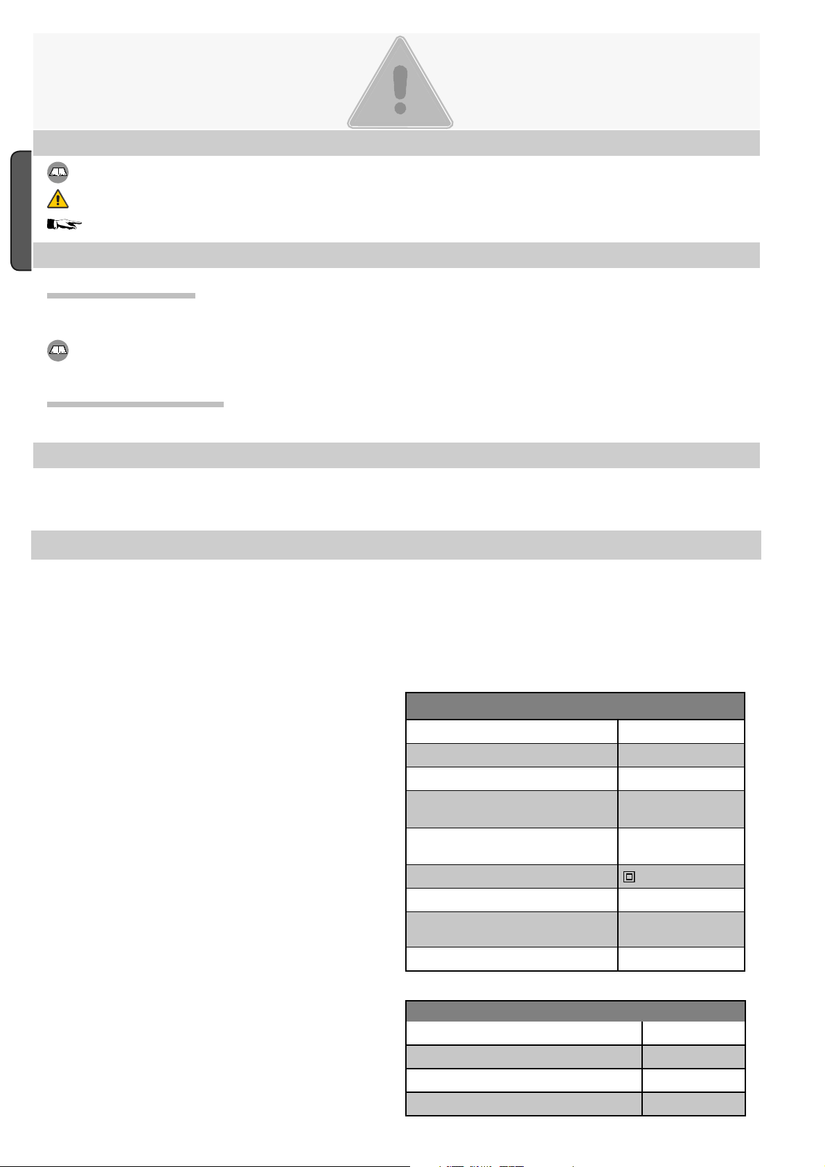
TECHNICAL DATA
Power supply
Maximum power rating 780 W
Power draw when idle
Maximum power for 24 V
accessories
Maximum power for 230 V
accessories
Circuit insulation class
Container material ABS
Protection rating of the container IP54
Working temperature - 20 / +55°C
230 V / 400 V - 60 Hz
50 mA
45 W
85 W
FUSE TABLE
to protect: fuses for:
Electronic board (line) A 8
Accessories A 2
Command devices (control unit) A 630
© CAME Cancelli Automatici S.p.A. - The data and information in this manual may be changed at any time and without obligation on the part of Came Cancelli Automatici S.p.A. to notify said changes.
04/2014
319T90 ver.
Manual code:
-
p.
Page 3
#!-%
240
240
320
165
#!-%
240
320
3
319T9 0
3
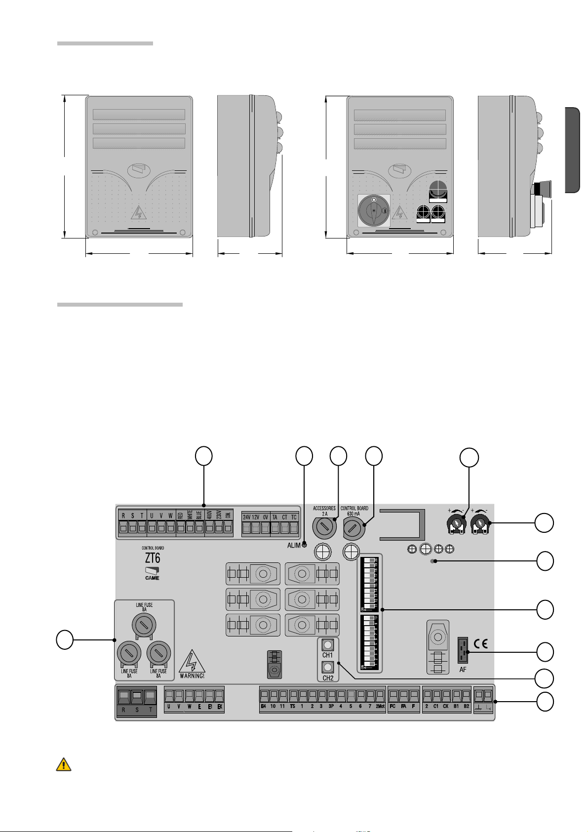
4.1 Dimensions
Z
TC overall dimensions ZT6C case overall dimensions
320
#!-%
240
4.2 Main components
1. Dip-switch selecting featur
Contr
2.
3. Accessories fuse 2 A F
4. Line fuse 8 A F
5.
6.
ol panel fuse 630mA F
AF radio frequency card socket
Power supply LED-signal light
es
240
#!-%
!02%
#()5$%
240
Radio code notifi cation LED light
7.
8. Connecting
terminals
9.Transformer connection terminals
10.
Buttons to memorise radio code
Trimmer TCA: adjusting automatic closing time
11.
12.
PART. OPEN TRIMMER.: adjusting open-par
ENGLISH
165
tially
4
© CAME Cancelli Automatici S.p.A. - The data and information in this manual may be changed at any time and without obligation on the part of Came Cancelli Automatici S.p.A. to notify said changes.
04/2014
319T90 ver.
Warning! Before acting on the device, cut off the main power supply.
Just operate the safety block on the ZT6C.
Manual code:
-
p.
2369
11
12
7
1
5
10
8
Page 4
4
319T9 0
3
5 Installation
5.1 Preliminary checks
Before beginning to install, the following is necessary:
ake sure that the point where the electrical panel is anchored is free from any impacts, and that the surface is solid and t
• M
roper tools and materials are used (i.e. screws, wall plugs, etc.).
p
• S
et up a suitable omni polar cut-off device, with distances greater than 3 mm between contacts, with sectioned power source.
Check that any connections inside the container (made for continuity purposes of the protective circuit) are fitted with extra
•
insulation compared to other internal conductive parts.
et up proper conduits and electric cable raceways, making sure these are protected from any mechanical damage
• S
ENGLISH
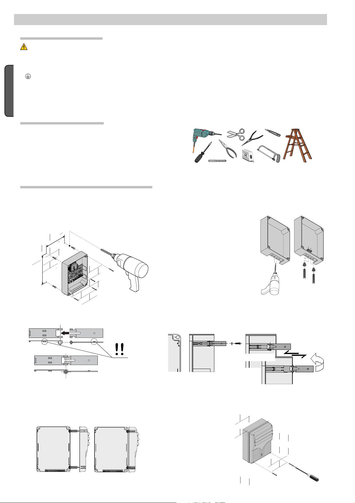
5.2 Tools and equipment
M
ake sure you have all the tools and materials needed to carry
out the installation in total safety and in accordance with current
regulations. Here are some examples.
5.3 Fastening and mounting the container
hat
.
1)Secure the base of the panel in a safe area; yes max. 6 mm
Head with to.
Assemble the pressure hinges.
forate the pre-punched holes and insert the cable glands
2) Per
with corrugated tubes for the electrical cables to run through.
N.B.: the pre-punched holes have 20
mm diameter
C
areful not to damage the electronic
.
board inside the panel!
4) in
sert the hinges into the housing (either left or right) and secure
them using the issued screws and washers.
15 mm ~
the slide to rotate
p the cover onto the hinges.
Sna
5)
fter adjusting and setting, secure the cover using the issue
6) A
ws.
scre
d
© CAME Cancelli Automatici S.p.A. - The data and information in this manual may be changed at any time and without obligation on the part of Came Cancelli Automatici S.p.A. to notify said changes.
04/2014
319T90 ver.
Manual code:
-
p.
Page 5

#!-%
#!-%
5
319T9 0
3
6 Electrical connections of the ZT6
Gearmotor
Tri-phase 400 V AC motor
001BK-2200T 001C-BXT
ENGLISH
Power supply
Control panel is 230
V AC single-phase
powered
#!-%
!02%
#()5$%
Terminals for powering the
24V AC accessories. Overall
allowed power: 45 W
#!-%
!02%
#()5$%
© CAME Cancelli Automatici S.p.A. - The data and information in this manual may be changed at any time and without obligation on the part of Came Cancelli Automatici S.p.A. to notify said changes.
04/2014
If the control panel is powered by 230V
319T90 ver.
Manual code:
-
p.
(single or three-phase), move the
short-circuit bridge connection as
shown.
Control panel is 230
- 400 V A
C T
power
ri-phase
ed
'Moving' 24 V AC output
Overall allowed power:
45 W
Page 6

6
319T9 0
3
Lighting and warning devices
Cycle/courtesy lamp (Contact capacity: 230 V - 60 W max.)
With dip switch 16 set to OFF and dip switch 17 set
16 17
Lights the area of operation. It remains on from
to ON = Cycle lamp.
18
the start of gate opening to complete closing (including the
automatic closing time).
With dip switch 16 set to ON and dip switch 17 set
ENGLISH
16 17
to OFF = Courtesy lamp.
18
Lights the area of operation; stays on for a set time
of 330 seconds after an opening command.
Flashing light (contact rated
for: 230V AC - 25W Max.)
Flashes while gate opens
and closes.
Gate open warning light
Contact rated for: 24 V - 3
W Max.)
Indicates that gate is open.
Gate open warning light
Contact rated for: 24 V - 3
W Max.)
Indicates that gate is
closed.
Command devices
Stop button ((N.C.) contact)
ate stop button that excludes automatic closing, to resume
G
movement press command or transmitter button.
If unused, set DIP-switch 10 to ON.
Key switch selector and/or opening button (N.O. contact)
Opening command
Key switch selector and/or opening button (N.O. contact)
Partial opening for pedestrian passage. The opening time can be
adjusted via the PART. OPEN. The automatic closing time is adjustable via DIP-switch 12.
Key switch selector and/or opening button (N.O. contact)
Closing command.
Key switch selector and/or command button (N.O. contact)
Gate opening and closing commands, pressing the button or turning
the key switch selector, the gate inverts its movement or stops
depending on selection made on the DIP switches (see selecting
functions, DIP switches 2-3)
© CAME Cancelli Automatici S.p.A. - The data and information in this manual may be changed at any time and without obligation on the part of Came Cancelli Automatici S.p.A. to notify said changes.
04/2014
319T90 ver.
Manual code:
-
p.
Page 7

7
319T9 0
3
Safety devices
C1 = Contact (N.C.) for reopening during closing.
Input for safety devices such as photocells, sensitive edges
and other devices compliant with the EN 12978 standard.
While the operator is closing, the opening of the contact
causes the reversal of the direction of movement until
completely open.
If C1 is not used, set dip switch 7 to ON.
CX with dip switch 8 and dip switch 9 OFF = Contact (N.C.)
for reclosing during opening.
Input for safety devices such as photocells, sensitive edges
and other devices compliant with the EN 12978 standard.
While the operator is opening, the closing of the contact
causes the reversal of the direction of movement until
completely closed.
CX with dip switch 8 OFF and dip switch 9 ON = Contact
(N.C.) for partial stop.
Input for safety devices such as photocells, sensitive edges
and other devices compliant with the EN 12978 standard.
Stops the operator, if it is moving, and then sets automatic
closing.
If CX is not used, set dip switch 8 to ON.
RX
RX
Photocells
DIR / DELTA-S
Photocells
DELTA
TX
ENGLISH
TX
Photocell safety connection
With each opening or closing command, the panel checks that the photocells work. Any
anomaly inhibits any command.
Set dip switch 13 to ON.
DELTA
© CAME Cancelli Automatici S.p.A. - The data and information in this manual may be changed at any time and without obligation on the part of Came Cancelli Automatici S.p.A. to notify said changes.
04/2014
319T90 ver.
Manual code:
-
p.
./
#
.#
DIR / DELTA S
#
48
.#
&53)"),%M!
48
48
Page 8

8
319T9 0
3
7 Selecting features
ENGLISH
1 ON - Automatic closing feature activated; (1OFF - deactivated)
2 ON - Open-stop-close-stop with button (2-7) and transmitter (AF card fitted) feature activated
2 OFF - Open-closewith (2-7) button and radio transmitter (AF card fitted) feature activated
3 ON - Open onlywith transmitter (AF card fitted) feature activated; (3 OFF - deactivated)
4 ON -Feature maintained action activated; (4OFF - deactivated)
5 ON - Pre flashing activated during opening and closing; (5 OFF - deactivated)
6 ON - Obstacle detection feature activated; (6 OFF - deactivated)
7 OFF - Reopen while closing (connect safety device on terminals 2-C1) feature activated; (7 ON - deactivated)
8 OFF / 9 OFF - Reclose while opening (connect safety device on terminals 2-CX) feature terminals
8 OFF / 9 ON - Partial stop(connect the safety device on terminals 2-CX) feature activated; (if the devices on 2-CX are unused,
set DIP switch 8 to ON)
10 OFF - Total stop(connect buttons on 1-2) feature activated; (10 ON - deactivated)
11 - Unused, keep DIP switch on OFF
12 ON - Partial opening (automatic closing is set to 8") feature activated
12 OFF - Partial opening feature (automatic closing is adjustable with the trimmer, if inserted) activated
13 ON - Safety test to check photocell efficiency feature activated; (13 OFF - deactivated)
14 - Unused, keep DIP switch on OFF
15 - Unused, keep DIP switch on OFF
16 ON -Feature courtesy lamp activated; (16 OFF - deactivated)
17 ON -Feature Cycle lamp activated ; (17 OFF - deactivated)
18 ON - Activate closing brake feature. Use only with the CBX and CBXT operators
19 -disconnected
20 -disconnected
8 Settings
+T.C. A-
Trimmer T.C.A. Adjusting automatic closing time from a minimum of 1 second to a maximum of 120 seconds.
PART. OPEN TRIMMER Adjusting partial opening from a minimum of 1 seconds to a maximum of 14 seconds.
+AP.PARZ.-
© CAME Cancelli Automatici S.p.A. - The data and information in this manual may be changed at any time and without obligation on the part of Came Cancelli Automatici S.p.A. to notify said changes.
04/2014
319T90 ver.
Manual code:
-
p.
Page 9

9
319T9 0
3
9 Connecting two control panels for control of a pair of gearmotors
With two coupled gearmotors, you can command only the opening (by button and/or radio control): the gate will close only in automatic closing mode.
Coordinate the direction of travel of the two gearmotors and , by modifying the motor’s rotation (invert the cables on terminals FA-FC and U-V).
Make the electrical connections only on the motor’s control board . Whereas, the adjustments and features, must be made on both boards.
Connect the two boards together, as illustrated. Set DIP 1 and 3 to ON on both boards.
Fit the AF board only into the gearmotor’s board .
The transmitter button for opening a gate must be memorized on the gearmotor’s channel CH1 . The transmitter button for opening both gates must
be memorized on the gearmotor’s channel CH2 .
ENGLISH
#!-%
#!-%
#!-%
#!-%
#!-%
© CAME Cancelli Automatici S.p.A. - The data and information in this manual may be changed at any time and without obligation on the part of Came Cancelli Automatici S.p.A. to notify said changes.
04/2014
319T90 ver.
CAME
Manual code:
-
p.
CAME
CAME
CAME
CAME
CAME
CAME
CAME
CAME
CAME
Page 10

10
319T9 0
3
10 Activating the radio command
Connect the antenna RG58 cable to the terminals and any accessory to connect to the B1-B2 output (N.O. contact) ❶.
For the AF43S / AF43SM radiofrequency cards only, position the jumper as shown according to the series of transmitters used ❷.
DISCONNECT POWER AND REMOVE THE BATTERIES, IF PRESENT. Insert the AF card on the control board.
N.B. the control board only recognises the AF card when the operator is powered again❸.
Hold down the CH1 key on the control board: the LED indicator flashes. Press a key on the transmitter to send the code. The LED will remain lit to indicate
SUCCESSFUL memorisation ❹.
Follow the same procedure with the CH2 key, associating it with another transmitter key ❺.
CH1 = channel for direct control of a panel function (OPEN ONLY, OPEN-CLOSE-REVERSE or OPEN-STOP-CLOSE-STOP, according to the selection made
on dip switches 2 and 3).
ENGLISH
CH2 = channel for commands directed to an accessory device connected on B1-B2 or for connecting two coupled motors having a single command.
❶
❷
Contact rating: 5 A-24 V DC
TOP
TAM
❸
Control board
Antenna
AF card
❹
Indicator LED
❺
© CAME Cancelli Automatici S.p.A. - The data and information in this manual may be changed at any time and without obligation on the part of Came Cancelli Automatici S.p.A. to notify said changes.
04/2014
319T90 ver.
Manual code:
10 -
p.
Page 11

11
319T9 0
3
11 Dismantling and disposal
On its premises, CAME Cancelli Automatici S.p.A. implements a certified Environmental Management System in compliance
with the UNI EN ISO 14001 standard to ensure environmental protection.
Please help us to safeguard the environment. At CAME we believe this to be one of the fundamentals of our market operations and
development strategies. Just follow these short disposal instructions:
DISPOSING OF THE PACKAGING
The components of the packaging (i.e. cardboard, plastic, etc.) are solid urban waste and may be disposed of without much trouble,
simply by separating them for recycling.
Before proceeding it is always a good idea to check your local legislation on the matter.
DO NOT DISPOSE OF IN NATURE!
PRODUCT DISPOSAL
Our products are made up of various materials. Most of these (aluminium, plastic, iron, electric cables) are solid urban waste.
These can be disposed of at local solid waste management dumps or recycling plants.
Other components (i.e. electronic cards, transmitter batteries, etc. ) may contain hazardous substances.
These must therefore be handed over the specially authorised disposal firms.
Before proceeding it is always a good idea to check your local legislation on the matter.
DO NOT DISPOSE OF IN NATURE!
ENGLISH
12 Compliance statement
Declaration - Came Cancelli Automatici S.p.A. declares that this device complies with the essential requirements and other relevant
provisions established in Directives 2014/30/UE and 2006/95/EC.
A true copy of the declaration of conformity is available upon request.
© CAME Cancelli Automatici S.p.A. - The data and information in this manual may be changed at any time and without obligation on the part of Came Cancelli Automatici S.p.A. to notify said changes.
04/2014
319T90 ver.
Manual code:
11 -
p.
Page 12

www. came.com
CAME Cancelli Au tomatici S.p.a.
Doss on Di Ca sier
Assis tenza Tecn ica/Numero Verde 800 295830
IT • Per ogni ulteriore informazione su azienda, prodotti e assistenza nella vostra lingua:
Engli sh
319T9 0
3
EN • For any further information on company, products and assistance in your language:
FR • Pour toute autre information sur la société, les produits et l’assistance dans votre langue :
DE • Weitere Infos über Unternehmen, Produkte und Kundendienst bei:
ES • Por cualquier información sobre la empresa, los productos y asistencia en su idioma:
NL • Voor meer informatie over het bedrijf, de producten en hulp in uw eigen taal:
PT • Para toda e qualquer informação acerca da empresa, de produtos e assistência técnica, em sua língua:
PL •
Wszystkie inne informacje dotyczące fi rmy, produktów oraz usług i pomocy technicznej w Waszym języku znajdują się na stronie:
RU •
Для получения дополнительной информации о компании, продукции и сервисной поддержке на вашем языке:
HU • A vállalatra, termékeire és a műszaki szervizre vonatkozó minden további információért az Ön nyelvén:
HR • Za sve dodatne informacije o poduzeću, proizvodima i tehničkoj podršci:
UK • Для отримання будь-якої іншої інформації про компанію, продукцію та технічну підтримку:
www. came.com
04/2014 © CAME Cancelli Automatici S.p.A.
319T90 ver.
English - Manual code:
The data and information in this manual may be changed at any time and without obligation on the part of Came Cancelli Automatici S.p.A. to notify said changes.
CAME Cancelli Automatici S.p.a.
Via Martiri Della Libertà, 15
31030
Dosson Di Casier (Tv)
(+39) 0422 4940
(+39) 0422 4941
Assistenza Tecnica/Numero Verde 800 295830
 Loading...