

Page 1
Control panel for CBXET
ZT5-ZT5C
INSTALLATION MANUAL
Page 2
“IMPORTANT INSTRUCTIONS FOR SAFE INSTALLATION”
CAUTION: INCORRECT INSTALLATION CAN CAUSE SERIOUS DAMAGE. PERFORM ALL THE
INSTALLATION INSTRUCTIONS
THIS MANUAL HAS BEEN WRITTEN SPECIFICALLY FOR A PROFESSIONAL INSTALLER OR OTHER
ENGLISH
SPECIFICALLY TRAINED PERSON.
1 Legend
This symbol indicates sections to be read with particular care.
This symbol indicates sections concerning safety.
This symbol indicates notes to communicate to users.
2 Destination and use Precautions applications
2.1 Destination
The ZT5-ZT5C electrical panel (ZT5C version with built-in command keys and safety lock) were designed to control CBXET
automation units in the movement of sectional, sliding and swing gates.
Precautions applications
2.2
- Comply with the distances and diameters of the cables shown in the table in Chap. 5.4
- Locate the panel in areas protected from accidental blows.
- For the ZT5C version, position the panel at a height of 1.5 m from the ground
3 Standards followed
The following standards were complied with for this product: EN 12978, UNI EN 954-1, CEI EN 60335-1, UNI EN 12453.
4 Description
4.1 Three-phase electric panel
Ratiomotor electrical panel with three-phase 230/400V power; 50÷60 Hz frequency.
Designed and built entirely by CAME Cancelli Automatici S.p.A. Case with air recycling inlet. 2-year guarantee unless tampered
with.
4.2 Technical information
All the data and information contained herein is considered subject to change at any time and at our discretion.
Electrical panel
Power supply: 230V / 400V - 50÷60 Hz.
Maximum power allowed: 780 W
Absorption at rest: 55 mA
Maximum power for 24V accessories: 20 W
Maximum power for 230V accessories: 200 W
Degree of protection: IP54
Insulation type: II
Material: ABS
Working temperature:
#
2
#
Page 3
ESC
ENTER
PROGRAMMING FUNCTION
S1 GND
AF
R700
RSE
R
S
T
W
RED
WHITE
BLU
400
230
COMM.
V
E
W
U
E1E
X
ACCESSORIES 1A
CONTROL BOARD 1A
CT
TC
24
TA
0
WARNI
NG!
ZT5
CONTROL BOARD
CONTRAST
- DISPLAY +
1 2 3 4 5 6 7 8 9 10 11 12
05 06 07 08 09 V1 V2 V3 V4 V5
#!-%
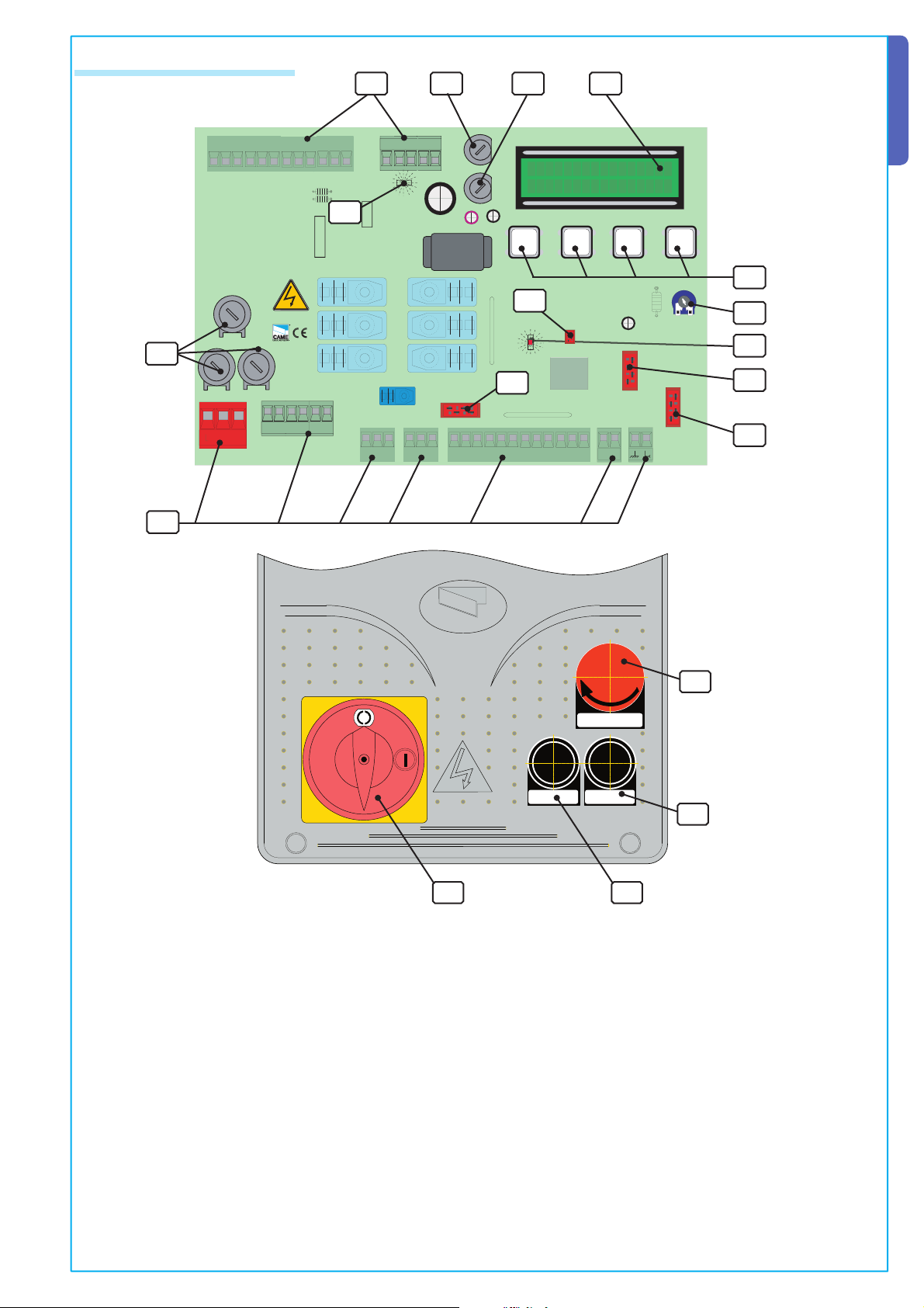
4.3 Main components
11
ENGLISH
32
1
ZT5-ZT5C data card
RRSSTTUUVVW
05 06 07 08 09 V1 V2 V3 V4 V5
1 2 3 4 5 6 7 8 9 10 11 12
,).%&53%!
4
,).%&53%! ,).%&53%!
10
RED
WHITE
WARNING!
CONTROL BOARD
ZT5
BLU
400
230
8
COMM.
AB
ACCESSORIES 1A
CONTROL BOARD 1A
PROGRAMMING FUNCTION
ESC
><
18
ENTER
- DISPLAY +
CONTRAST
12
13
9
7
RSE
-
+E
'.$
P
1
2
45
7
#8 #9
R700
AF
43
5
6
Push button panel ZT5C box
#!-%
14
15
1-Display
1617
2- 1A fuse for accessories
3- 1A fuse for control unit
4- 8A line fuses
All the data and information contained herein is considered subject to change at any time and at our discretion.
5- R700 board connector
6- AF board connector
7- RSE board connector for signal decoding for PC interfacing (for multiple control of up to 16 units)
8- Power LED indicator
9- Activated safety contacts LED indicator
10- Connection terminal board
11- Transformer connection terminal board
12- Programming keys
13- Display screen contrast adjustment trimmer
14- STOP key
15- CLOSE key
16- OPEN key
17- Safety lock
18- Memory roll (system and user data backup device) board connector
3
Page 4
240
320
145
#!-%
240
320
165
#!-%
5 Installation
5 .1 Preliminary checks
ENGLISH
Before proceeding with the installation, it is necessary to:
• Check that the control panel is installed in an area protected from bumps and that the anchorage surface is solid, and that it
is secured with suitable elements (screws, inserts, etc).
• Provide for suitable omnipolar disconnection device with more than 3 mm between contacts to section power supply.
• Connections inside the case made for protection circuit continuity are allowed as long as they include additional insulation
with respect to other internal drive parts.
• Install suitable tubes and ducts for electric cable passage to guarantee protection against mechanical damage.
5.2 Equipment and materials
Make sure all the necessary tools and materials are available to carry out the installation with the maximum safety, in compliance with regulations in force. Here are some examples.
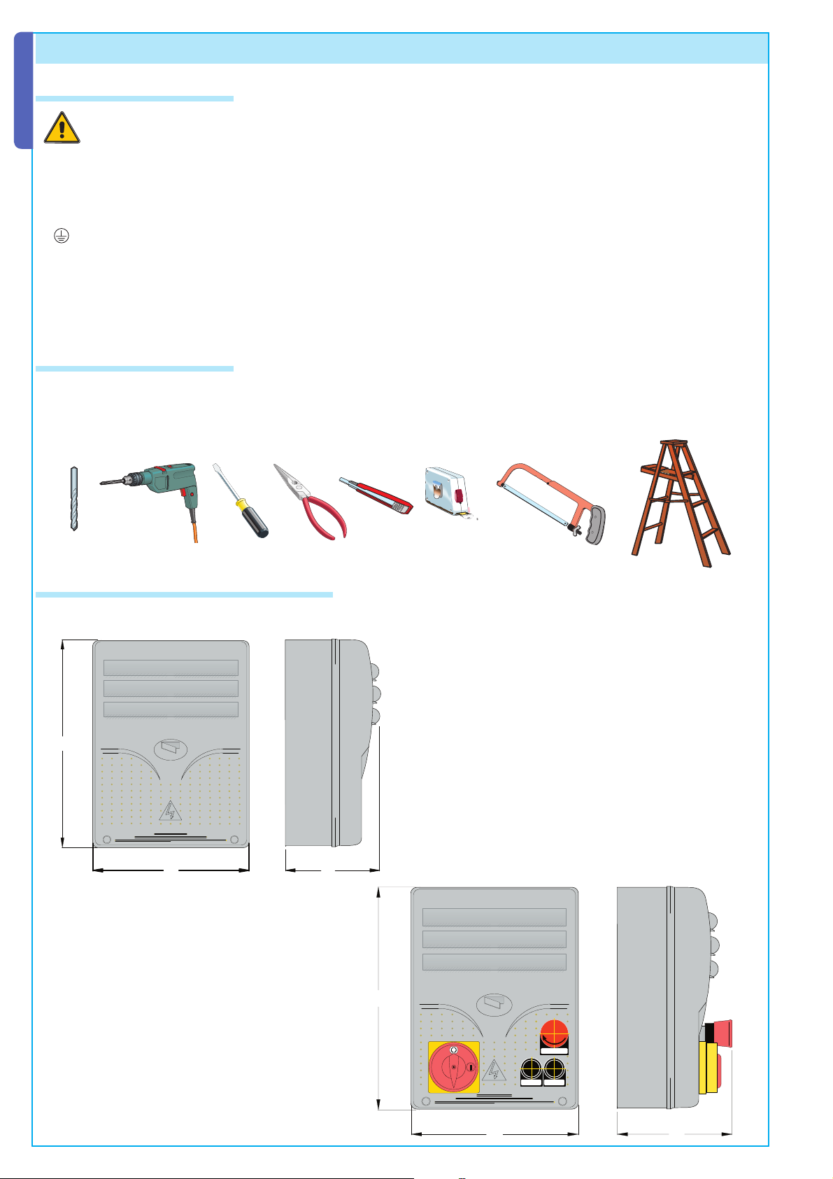
5.3 Dimensions, axle bases and fastening holes
Max. 6 mm Phillips round head screws are recommended.
320
#!-%
240
145
Dimensions of ZT5 C case
Dimensions of ZT5 case
All the data and information contained herein is considered subject to change at any time and at our discretion.
320
#!-%
240
!02%
#()5$%
165
4
Page 5
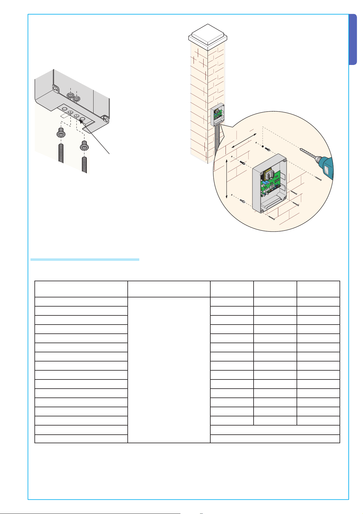
The holes measure
20/21 mm diameter
ENGLISH
215
295
5.4 Minimum thickness and type of cables
Connections Type of cable
230/400V 3F power supply line
230V 2F power supply line 3G 1,5mm² 3G 2,5mm² 3G 4mm²
230/400V 2F/3F motors 4G 1mm² 4G 1,5mm² 4G 2,5mm²
24V motors 2 x 1mm² 2 x 1,5mm² 2 x 2,5mm²
230V fl ashing lamp 2 x 0,5mm² 2 x 1mm² 2 x 1,5mm²
24V fl ashing lamp 2 x 0,5mm² 2 x 1mm² 2 x 1,5mm²
230V courtesy / cycle light 3G 0,5mm² 3G 1mm² 3G 1,5mm²
24V power supply accessory 2 x 0,5mm² 2 x 0,5mm² 2 x 1mm²
All the data and information contained herein is considered subject to change at any time and at our discretion.
24V pilot light 2 x 0,5mm² 2 x 0,5mm² 2 x 1mm²
24V “in motion” output 2 x 0,5mm² 2 x 0,5mm² 2 x 1mm²
Safety contacts 2 x 0,5mm² 2 x 0,5mm² 2 x 0,5mm²
N.O./N.C. control button 2 x 0,5mm² 2 x 0,5mm² 2 x 0,5mm²
End stop 3 x 0,5mm² 3 x 1mm² 3 x 1,5mm²
Command 2nd combined motor 1 x 0,5mm² 1 x 0,5mm² 1 x 1mm²
Antenna connection (max 50M) RG58
Encoder connection (max 30M) 2402C 22AWG shielded cable
FROR CEI 20-22
CEI EN 50267-2-1
Length of
cable 1<10 M
4G 1,5mm² 4G 2,5mm² 4G 4mm²
Length of cable 10<20 M
Length of cable 20<30 M
N.B.: An evaluation of the size of the cables with lengths other than the data in the table must be made based on the effective
absorption of the connected devices, according to the instructions indicated by the CEI EN 60204-1 standards.
For connections that require several loads on the same line (sequential), the size given on the table must be re-evaluated based
on actual absorption and distances.
5
Page 6

V
E
W
U
E1
EX
V
E
W
U
E1
EX
R
S
T
V
E
W
U
E1
EX
+ E
5.5 Electrical connections
ENGLISH
T
5
230/400V A.C. power supply; three phase (ZT5)
Connections on R, T, S 230/400V A.C. power supply; three-phase (ZT5C )
R
1
S
3
230V/400V 50÷60 H three-phase motor ,Maximum power: 780W
M
230V A.C. 25W max. (in motion) output for flashing lamp
AB
+E
6
GND
-
230V max. 60W courtesy or cycle light (select from software)
Serial communication for PC connection, use mod. RS235 shielded bipolar cable with software (optional)
PC 40 or PC30
RS232 cable
Personal
Computer
-
+
Connection for encoder (for connection between automation and electrical panel, use
+E
E
-
-
shielded 2402C 22AWG cable)
E
-
All the data and information contained herein is considered subject to change at any time and at our discretion.
Page 7

><
R700R700
AF
S1 GND
5.5 Electrical connections
ENGLISH
10 11 1 23 457
10 11 1 23 457
10 11 1 23 457
10 11 1 23 457
3P
3P
3P
3P
CX CY TS
(1-2) STOP Button N.C.
CX CY TS
(2-3P) Partial opening N.O. button
CX CY TS
(2-3) Total opening N.O. button
CX CY TS
(2-4) Closure N.O. button
10 11 1 23 457
10 11 1 23 457
3P
3P
All the data and information contained herein is considered subject to change at any time and at our discretion.
10 11 1 23 457
3P
Antenna connection
TS
CX CY TS
(2-7) Open-close contact (Step step)
or Open-stop-close-stop (Sequential) N.O.
CX CY TS
(10-5) Open pilot light 24V 3W
CX CY TS
10-11 output 24V A.C power supply accessories, max 20 W
AF
7
Page 8

><
R700
AF
S1 GND
><
R700
AF
S1 GND
5.5 Electrical connections
ENGLISH
10 2 TX C NC
10 11123p
10 2 TX C NC
Rx
Rx
DIR
3
457CX CY
DIR
Tx
(2-CX) photoelectric cell DOC and DIR connection
DOC
Rx
-
+
N.O.
C.
N.C.
Tx 2
TS
Tx
(2-CY) photoelectric cell DOC and DIR connection
10 11123p
3
457CX CY
Tx
+
-
TS
DOC
Tx
+
-
Tx 2
Rx
-
+
N.O.
C.
N.C.
10 11123p
Rx
10 2 TX C NC
10 11123p
3
457CX CY
DIR
3
457CX CY
TS
Tx
Photoelectric cell DOC and DIR functional test
10 11123p
3
457CX CY
TS
DOC
Rx
-
+
N.O.
C.
N.C.
Tx 2
TS
10 11123p
3
457CX CY
Tx
+
-
TS
(S1-GND) connection of sensors TSP00 (transponder) LT001 (swipe)
N.B. for the sensors to recognize the card, connect them with the special decoder card (R700).
LT001
R700
TS
R700
AF
CANCELLIAUTOMATICI
R700
CANCELLIAUTOMATICI
R700
All the data and information contained herein is considered subject to change at any time and at our discretion.
ACCESSCONTROL
8
Rosso
Nero
TSP00
C
AME
TS
AF
Nero
Rosso
Page 9

PROGRAMMING FUNCTION
PROGRAMMING FUNCTION
ESC
ENTER
>
<
PROGRAMMING FUNCTION
ENTER
ESC ENTER
><
PROGRAMMING FUNCTION
PROGRAMMING FUNCTION
ENTER
PROGRAMMING FUNCTION
PROGRAMMING FUNCTION
PROGRAMMING FUNCTION
PROGRAMMING FUNCTION
PROGRAMMING FUNCTION
ENTER
ESC ENTER
><
PROGRAMMING FUNCTION
ENTER
ENTER
6 Planning
6.1 Description display controls
PROGRAMMING FUNCTION
ENGLISH
The ENTER key serves to :
- enter the menu
- confirm and memorize the set value
ENTER
WWW.CAME.IT
<>
ESC
LANGUAGE
WWW.CAME.IT
<
6.2 Menu browsing
To enter the menu, press and keep
the ENTER key depressed for at
ENTER
least one second.
><
CBXET
CBX
>
To select the menu
item, use the arrows
to move to the item
desired.
ENTER
The ESC key serves to :
- exit the menu
ESC
<
...........
<>
<>
- cancel the modifications
The < > keys serve to:
- move from one menu item to another
- increase or decrease a value
><
The <.....> indicators on the display serve to:
>
- indicate the item currently selected
LANGUAGE
LANGUAGE
<>
TIMES
ENTER
><
All the data and information contained herein is considered subject to change at any time and at our discretion.
T.C.A.
<>
20 sec
<>
T.C.A.
45 sec
For submenus, use
the arrows to move to
the item desired.
If the <> arrow keys are
on the time, it means
that it can be modified.
ENTER
.. Then press the ENTER key to
confirm.
.. then press ENTER
Operation time
<>
12 sec
<>
T.C.A.
20 sec
.. then press ENTER
Increase or decrease a value using the arrow keys to
reach the value desired...
><
To exit the menu, wait 30
seconds or press ESC until the
start window appears
ENTER
ESC
N.B. it is not possible to move around when the menu is active.
9
Page 10

>
>
>
><
><
< >
< >
>
>
>
>
>
>
< >
< >
>
>
>
>
>
>
>
< >
< >
< >
< >
< >
>
>
>
< >
< >
>
>
><
><
>
>
>
< >
< >
< >
>
>
>
>
>
< >
< >
< >
< >
< >
< >
< >
< >
< >
< >
< >
< >
>
>
>
>
>
>
>
>
< >
< >
< >
>
< >
< >
>
>
>
6.3 Menu structure
ENTER
ENGLISH
Press ENTER for 1 second
LANGUAGE
TIMES
FUNCTIONS
RADIO /
USERS
CALIBR .
INFO
ENTER
ENTER
ENTER
New user
Change user
Delete user
Save memory
Load memory
Cancella tutti
ENTER
Ru n calibrat.
Obstr.sen sitive
Partial ap. run
Network ID
ENTER
Version
No. manoeuv.
Startup mess.
Operat. time
A.C.T.
ENTER
Flashing time
A.P.C. time
Courtesy time
ENTER
Ra dio fu n ct.
Part. opening
ENTER
n.5 empty
ENTER
n.5 empty
ENTER
ENTER
ENTER
ENTER
ENTER
(Read only)
(Read only)
ENTER
< 10 sec >
ENTER
n.4 exists
< >
< >
n.4 exists
< >
< >
ENTER
W ri ti n g ...
ENTER
Re a di n g ...
con firm?
<Y>
P ro ce d u r a ....
< >
< >
<N>
< 15% >
< >
< 40% >
< >
1 <-> 16
P ro ce d u r a ....
ENTER
< >
ENTER
< 10 sec >
< >
ENTER
ENTER
< >
Service test
< >
Detect obstacle
Closin g pu sh
< 10 sec >
< >
< 10 sec >
< >
< 10 sec >
< >
Aut. closure
2-7 control
User function
W. flashing
Dead Man
Dead Man clos.
C1 Entryw ay
CX Entryway
Total sto p
Ex outlet
Open indicator
Lang. selec.
ENTER
Italian
English
French
Dutch
Spanisch
German
ENTER
ENTER
ENTER
ENTER
ENTER
ENTER
ENTER
ENTER
Disact
ENTER
ENTER
Attivo su CX/CY
ENTER
ENTER
ENTER
ENTER
<ON >
Sequential
Step-by-step
2-7 control
<ON >
<ON >
C1
F.C2
Enabled
OFF
<ON >
<ON >
Intermittente
Continua
< >
<OFF>
Opens only
< >
<OFF>
< >
<OFF>
<OFF>
<ON >
< >
Disabled
< >
Disabled
< >
Cycle
Movement
< >
<OFF>
< >
<OFF>
C2
F.C3
F.C4
< >
< >
< >
< >
< >
< >
< >
< >
All the data and information contained herein is considered subject to change at any time and at our discretion.
10
Page 11

6.4 Menu entries
>
>
>
>
< >
< >
>
< >
< >
< >
>
>
>
>
>
< >
< >
< >
< >
>
>
>
Language
Language selection: This selects the language of the menu from the available languages.
LANGUAGE
ENTER
Lang. select
ENTER
Italian
German
English French
Spanisch
Dutch
Time
Operating time: motor operating time during a single 10” to 120” opening or closing operation.
TIMES
ENTER
T.C.A. : automatic closing time from 1” to 120” after an opening command is carried out.
TIMES
ENTER
Oper. time
ENTER
x 1
T.C.A.
< 10 sec >
< >
ENGLISH
ENTER
< 10 sec >
< >
Pre-flashing time: pre-flashing duration: 1” to 5”.
TIMES
ENTER
x 2
Pre-flashing
ENTER
< 5 sec >
< >
Pedestrian T.C.A.: 1” to 120” automatic closing time after the execution of a pedestrian opening operation.
TIMES
x 3
Pedestr. T.C.A.
ENTER
< 10 sec >
< >
ENTER
Courtesy time: the courtesy light remains on from 1” to 120”.
TIMES
x 3
Courtesy time
ENTER
< 10 sec >
< >
ENTER
Functions
Automatic closure: enables or disables the automatic closing function.
ENTER
x 1
Automatic cl.
ENTER
2-7 command
<ON >
< >
<OFF>
FUNCTIONS
ENTER
Command 2-7: sets the sequential or stepper contact.
All the data and information contained herein is considered subject to change at any time and at our discretion.
FUNCTIONS
ENTER
Sequential
Step-by-step
< >
User function: sets the user or the opening only command or the function associated with command 2-7
FUNCTIONS
ENTER
x 2
User function
ENTER
2-7 comman d
Opens only
< >
Pre-flashing: enables or disables the pre-flashing function.
FUNCTIONS
ENTER
Pre-flashing
x 3
ENTER
<ON >
< >
<OFF>
11
Page 12

>
< >
>
< >
>
< >
>
>
>
>
>>
>
>
> >
>>
>
< >
>
> >
>
>
< >
>
< >
< >
>
6.4 Menu entries
Dead Man (maintained action): enables or disables the function (maintained action).
FUNCTIONS
ENGLISH
ENTER
x 4
Dead man
ENTER
<ON >
<OFF>
< >
Closing Dead Man (maintained closing action): enables or disables the function (maintained action during closing).
FUNCTIONS
ENTER
Clos. dead man
ENTER
<ON >
<OFF>
< >
x 5
CY inlet: N.C. safety contact inlet with the option to associate the following functions
C1: Reopening while closing, C2: Reclosing while opening, C3: partial stop, C4: Obstacle wait,
C6: Reopening while closing (for safety rib).
FUNCTIONS
ENTER
x6
CY inlet
ENTER
C1
Disabled
C2 C3
C6
C4
CX inlet: N.C. safety contact inlet with the option to associate the following functions
C1: Reopening while closing, C2: Reclosing while opening, C3: Partial stop, C4: Obstacle wait,
C6: Reopening while closing (for safety rib).
FUNCTIONS
ENTER
x7
CX inlet
ENTER
C1
Disabled
C2 C3
C6
C4
Total Stop: enables or disables total stop.
FUNCTIONS
ENTER
x 8
Total sto p
ENTER
<ON >
< >
<OFF>
Service test: checks the correct functioning of safety devices and selects the inlets they are connected to.
FUNCTIONS
ENTER
x 9
Service test
ENTER
<OFF >
Attivo s u CX
Attivo s u CYAttivo su CX/CY
Lamp output: output for connection of 230V lamp that may be set in two function modes
- Cycle: the flashing lamp is in function until the automatism returns to the closing position.
-Movement: the flashing lamp works only while the automatism is moving.
FUNCTIONS
ENTER
x 10
Lamp output
ENTER
Cycle
Movement
< >
Reveal obstacle: prevents movement with the motor shut down until the safety devices detect an obstacle
FUNCTIONS
ENTER
x 11
Obstacle detec.
ENTER
<ON >
< >
<OFF>
All the data and information contained herein is considered subject to change at any time and at our discretion.
Closing push: added push to improve closure. (May be used if the pavement is irregular)
FUNCTIONS
ENTER
x 12
Closin g pu sh
ENTER
<ON >
<OFF>
< >
Open indicator: enables the movement signalling indicator.
FUNCTIONS
ENTER
x 14
Open indicator
ENTER
Intermittente
Continua
< >
12
Page 13

6.4 Menu entries
>
>
>
< >
>
>
>
>
< >
>
>
< >
>
< >
>
< >
ENGLISH
Radio/User
Shut the power off prior to inserting a coding board to the control panel (see pg. 15).
New user: to create new users
RADIO /U SERS
ENTER
New user
Vedere descrizione dettagliata
Change user: to make changes in the functions associated to users.
RADIO /U SERS
ENTER
x 2
New user
Vedere descrizione dettagliata
Remove user: to delete users.(see pg. 14)
RADIO /U SERS
ENTER
x 3
Remove user
ENTER
n.4 exists
n.5 empty
Save memory: to save users in the memory roll.
RADIO /U SERS
ENTER
x 4
Save memory
ENTER
Writin g ...
Load memory: to load the data saved in the memory roll.
RADIO /U SERS
ENTER
x 5
Load memory
ENTER
Re a di n g ...
Delete all: to delete all saved users.
RADIO /U SERS
ENTER
x 6
Delete all
ENTER
Confirm?
<Y>
ENTER
ENTER
< >
< >
<N>
Calibration
Run calibration: Adjusts the gate’s run and the direction of Opening/Closing. (see pg. 14).
CALIBR .
ENTER
New user
Vedere descrizione dettagliata
Rib sensor: adjusts the gate’s sensitivity should obstacles be detected during movement.
CALIBR .
ENTER
x 2
Saf. rib sen.
ENTER
+oooo-
•
< >
Partial opening run: adjusts the partial opening run.
All the data and information contained herein is considered subject to change at any time and at our discretion.
CALIBR .
ENTER
x3
Partial ap. run
ENTER
< 40% >
< >
Network ID: Assigns a value from 1 to 16 for recognition via software
CALIBR .
ENTER
x 4
Network ID
ENTER
< >
1 <-> 16
INFO
Version: Displays the version of the software
Number of operations: Displays the number of the operations made.
Initial message: Sets the initial message on the display.
INFO
ENTER
Startup message
Vedere descrizione dettagliata
13
Page 14

ESC
ENTER
PROGRAMMING FUNCTION
>
<
ESC
ENTER
>
<
PROGRAMMING FUNCTION
ESC
ENTER
PROGRAMMING FUNCTION
ESC
ENTER
PROGRAMMING FUNCTION
>
<
ESC
ENTER
>
<
PROGRAMMING FUNCTION
ESC
ENTER
PROGRAMMING FUNCTION
>
<
ESC
ENTER
PROGRAMMING FUNCTION
>
<
ESC
ENTER
>
<
PROGRAMMING FUNCTION
ESC
ENTER
PROGRAMMING FUNCTION
>
<
6.5 Run adjustment
1
From the adjustment menu,
select Run adjustment and confirm by
ENGLISH
pressing ENTER
Run calibration
<>
2
Execute a complete run of opening
using (< >), to reach the maximum
opening point.
Esegui una corsa
comleta d'ap.
ESC
4
Execute a complete run of closing
<
>
ENTER
ESC
5
Confirm by pressing ENTER.
using (< >), to reach the maximum
closing point.
Esegui una corsa
comleta di ch.
3
Then confirm by pressing
ENTER.
><
ENTER
6
Move the gate toward opening
for at least 3 seconds
Sel.dir Apertura
<>:muove ENT:OK
ESC
7
Afterwards, confirm by pressing
><
ENTER
Saved direction
Wait...
ESC
10
Use the (< >) to bring the gate to
><
the maximum opening point.
Set opening p.
<>:Move ENT:OK
ENTER
ENTER
8
Use the (< >) to bring the gate to
the closing point.
Set closing point
<>:Move ENT:OK
ESC
11
Then confirm by pressing ENTER.
><
Calibration OK
Wait...
ENTER
ESC
9
Confirm by pressing ENTER.
Closing point saved
><
ENTER
Wait...
ESC
12
If the calibration was not
<
>
ENTER
performed correctly or was
unsuccessful, one of the following
messages will appear:
- reprogram..... and then restart from
point 1.
All the data and information contained herein is considered subject to change at any time and at our discretion.
ESC
13
Move the wheel toward + or
- according to the instructions on the
display
Move 6 notches
in direction (+)
14
- reposition the encoder ... proceed
><
ENTER
ESC
<
>
ENTER
with point 13
14
Confirm by pressing Enter
restart from point 1
Adjustment ok
run calibration
Press Enter
to end
Page 15

ESC
ENTER
PROGRAMMING FUNCTION
>
<
ESC
ENTER
PROGRAMMING FUNCTION
ESC
ENTER
PROGRAMMING FUNCTION
ESCESC ENTERENTER
><
PROGRAMMING FUNCTIONPROGRAMMING FUNCTION
S1 GND
1
2
P
45
7
#8 #9
43
+E
-
AB
'.$
AFAF
R700R700
RSERSE
COMM.COMM.
ACCESSORIES 1AACCESSORIES 1A
CONTROL BOARD 1ACONTROL BOARD 1A
CT
T
C
24
T
A
0
CONTRASTCONTRAST
- DISPLAY +- DISPLAY +
6.6 Decoder cards
To control the card by radio controls or passes, connect the AF radio card desired with the respective radio control and for the
R700 card for TSP00/LT001 proximity sensors.
N.B. if the appropriate decoding board is not included, it is not possible to enter users (the maximum no. of users
that may be entered is 250)
AF and R700 boards should be inserted with the power switched off.
Frequency/MHz Board Trasmitter
ENGLISH
6.7 Add user.
1
From the Radio/Users, select New User
confirm by pressing ENTER
New User
<>
R700
CANCELLIAUTOMATICI
FM 26.995 AF130 TFM
FM 30.900 AF150 TFM
AM 26.995 AF26 TOP
AM 30.900 AF30 TOP
AM 433.92 AF43S / AF43SM TAM / TOP
AM 433.92 AF43SR ATOMO
AM 40.685 AF40 TOUCH
2
Select either the user function and partial opening
function to associate with the user, then confirm
with ENTER...
Ass. function
User function
<>
3
the radio control, swipe pass or transponder, depending on
the type of sensors installed in the system in question.
All the data and information contained herein is considered subject to change at any time and at our discretion.
<>
4
new code or number.
<>
ESC
..a message will prompt entering the correct code with
><
ENTER
As soon as the machine reads the code of the radio
control or pass, the message “Memorized” will appear
n. 1 Await. cod
.....
In any case, the window will appear prompting if we want to enter a
Another code?
NO
Another code?
<>
YES
ESC
><
ENTER
if the code is not present in the card,
otherwise an error will be signalled.
ACCESSCONTRO L
n. 1 Await. cod
Saved!
n. 2 Await. cod
n. 1 exist
If we select NO, we will terminate the user
entry procedure. If we select YES, the
operations will resume from
point 3.
ESC
><
ENTER
15
Page 16

ESC
ENTER
PROGRAMMING FUNCTION
ESC
ENTER
PROGRAMMING FUNCTION
ESC
ENTER
PROGRAMMING FUNCTION
>
<
ESC
ENTER
PROGRAMMING FUNCTION
>
<
ENTER
><
ENTER
ESC ENTER
><
PROGRAMMING FUNCTION
6.8 Change users (user function)
1
Select Change user from the Radio/
User menu. Confirm by pressing ENTER
ENGLISH
Change users
<>
ESC
3
Select the function to associate with the user, confirm by pressing ENTER.
><
ENTER
2
Select the user whose associated function needs to be changed using
the <> keys to move or press the transmitter key associated with it or swipe
the card on the sensor, confirm by pressing ENTER.
Change user
<>
n.1 exist
ESC
P.S. Confirming with ENTER, brings back the Change User window.
Ass. function
User function
<>
Ass. function
<>
Part. opening
ACCESSCONTROL
><
ENTER
ESC
><
ENTER
6.9 Change the initial message
1
Select Initial message from the INFO
menu, confirm by pressing ENTER
ENTER
Startup mess.
<>
WWW.CAME.IT
ESC
2
Move inside the display as explained previously to obtain the desired message.
><
ENTER
ESC
The maximum limit of characters is 32 or 16 per row.
Once the message is written, keep the ENTER key pressed for at least 3 seconds.
The ENTER key serves to :
- Move the cursor to the right
- If pressed for more than 3 seconds, it confirms
The ESC key serves to :
- Move the cursor to the left
- If pressed for more than 3 seconds, it exits
The < > keys serve to:
- select the letter desired and the space key
><
>
ENTER
All the data and information contained herein is considered subject to change at any time and at our discretion.
16
WWW.CAME.IT
CBXET
Page 17

6.10 Error Messages
“STOP contact open”: check the correct connection or the efficiency of the device connected.
“Service Test!!!”: There is a malfunction with the connected safety devices.
“Encoder not working: check the correct connection or the efficiency of the device connected.
“CX-CY contact open”: check the correct connection or the efficiency of the device connected.
7 Case Cover Assembly
ENGLISH
!!
1
Assemble the spring-type hinges.
Snap the cover
onto the hinges,
close and secure
with screws
provided.
3
8 Disposal
This product, including packaging, is made of different materials that may be recycled.
Please inquire on disposal or recycling systems for the product in compliance with local regulations in force.
2
Insert the hinges in the case (on the right or
left side) and secure them with the screws
and washers provided.
They must slide in order
to turn
15 mm~
Some electronic components could contain polluting substances, please dispose of properly.
9 Maker’s statement
MANUFACTURER’S DECLARATION
All the data and information contained herein is considered subject to change at any time and at our discretion.
Enclosed with the technical documentation (the original copy of the Declaration is available on request)
The representatives of
CAME Cancelli Automatici S.p.A.
via Martiri della Libertà, 15
31030Dosson di Casier - Treviso - ITALYtel
(+39) 0422 4940 - fax (+39) 0422 4941
internet: www.came.it - e-mail: info@came.it
Hereby declare, under their own respons ibility, that the product/s called ...
ZT5 - ZT5C
… comply with the Italian National Legal Provisions that transpose the
following Community Directives (where specifi cally applicable):
ACHINERY DIRECTIVE 98/37/CE
M
OW VOLTAGE DIRECTIVE 73/23/EEC - 93/68/EEC
L
ECTROMAGNETIC COMPATIBILITY DIRECTIVE 89/336/EEC - 92/31/EEC
L
IRECTIVE 1999/5/CE
R&TTE D
As per Enclosure II B of Machinery Directive 98/37/CE
Also, they furthermore represent and warrant that the product/s that are the subject of the present
Declaration are manufactured in the respect of the following main harmonized provisions:
EN 292 PART 1 AND 2 MACHINERY SAFETY.
EN 12453 I
EN 12445 I
EN 12978 SAFETY DEVICES FOR POWER OPERATED DOORS AND GATES ....
EN 60335 - 1 SAFETY IN APPARATUSES FOR HOME USE.
EN 60204 - 1 MACHINERY SAFETY.
EN 61000 - 6 - 2 E
EN 61000 - 4 - 4 E
EN 61000 - 4 - 5 ELECTROMAGNETIC COMPATIBILITY.
IMPORTANT CAUTION!
It is forbidden to market/use product/s that are the subject of this declaration before completing and/or
incorporating them in total compliance with the provisions of Machinery Directive 98/37/CE
TECHNICAL MANAGER
Mr. Gianni Michielan
Date of the present declaration 07/12/2001
NDUSTRIAL, COMMERCIAL AND OTHER CLOSING MECHANISMS.
NDUSTRIAL, COMMERCIAL AND OTHER CLOSING MECHANISMS.
LECTROMAGNETIC COMPATIBILITY.
LECTROMAGNETIC COMPATIBILITY.
Signatures of the Representatives
MANAGING DIRECTOR
Mr. Paolo Menuzzo
17
Page 18

CAME UNITED KINGDOM LTD
UNIT 3, ORCHARD BUSINESS PARK
TOWN STREET, SANDIACRE
NOTTINGHAM - NG10 5BP - U.K.
Tel 0044 115 9210430
Fax 0044 115 9210431
Cod.319T75 V2.1-11/05 © CAME CANCELLI AUTOMATICI
 Loading...