

Page 1
SERIE Z |
Z
SERIES
| SÉRIE Z |
BAUREIHE
Z |
SERIE Z
Documentazione
Tecnica
CANCELLI AUTOMATICI
QUADRO COMANDO
ELECTRIC CONTROL PANEL
ARMOIRE DE COMMANDE
SCHALTTAFEL
CUADRO DE MANDO
ZT4C
S93
rev. 0.4
03/2004
©CAME
CANCELLI
AUTOMATICI
319S93
ITALIANOITALIANO
ITALIANO
ITALIANOITALIANO
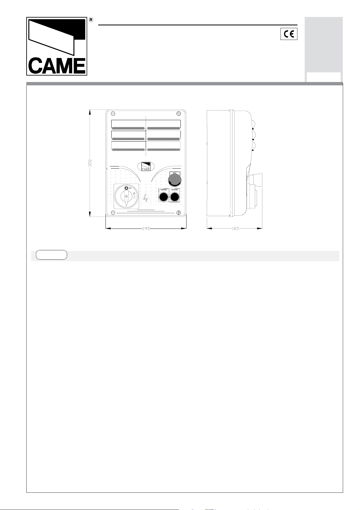
CARATTERISTICHE GENERALI
Descrizione quadro comando
Quadro elettrico per motoriduttori con
alimentazione 230V monofase/trifase
o 400V trifase; frequenza 50÷60 Hz.
Progettato e costruito interamente
dalla CAME Cancelli Automatici
S.p.A., risponde alle vigenti norme di
sicurezza, con grado di protezione
IP54. Scatola in ABS, dotata di presa
per il riciclo d'aria, blocco di
sicurezza, pulsanti apre, chiude, stop.
Garantito 24 mesi salvo
manomissioni.
Il circuito va alimentato sui morsetti R, S e
T (con alimentazione a 400V trifase) oppure solo sui morsetti R e S (con alimentazione a 230V monofase/trifase ), protetto in ingresso con fusibili da 8A.
Il quadro comando ZT4C è predisposto
per l'alimentazione a 400V. Nel caso di
alimentazione a 230V spostare il
collegamento che cortocircuita i morsetti
«380» e «COM» sui morsetti «220»
e«COM» (vedi pag.12).
Page 2

I dispositivi di comando sono a bassa
Accessori collegabili
tensione (24V), e sono protetti con
fusibile da 2A. La potenza complessiva
degli accessori a 24V, non deve
superare i 20W.
Il tempo lavoro è fisso a 120 secondi.
Sicurezza
Le fotocellule possono essere collegate e predisposte per:
-
Riapertura
-
Richiusura
in fase di chiusura (2-C1);
in fase di apertura (2-CX,
vedi dip 8-9);
-
Stop parziale,
arresto del cancello se
in movimento con conseguente predisposizione alla chiusura automatica
- Lampada ciclo o lampada di cortesia
(60 Watt, vedi pag. 16);
Altre funzioni selezionabili
-
Chiusura automatica.
Il
temporizzatore di chiusura automatica
si autoalimenta a finecorsa in apertura.
Il tempo prefissato regolabile, é comunque subordinato all'intervento di
eventuali accessori di sicurezza e si
esclude dopo un intervento di «stop»
totale o in mancanza di energia elettrica;
-
Apertura parziale.
Apertura del
cancello per passaggio pedonale,
viene attivata collegandosi ai morsetti
(2-CX, vedi dip 8-9);
-
Stop totale
(1-2), arresto del cancello
con esclusione dell'eventuale ciclo di
chiusura automatica; per riprendere il
movimento bisogna agire sulla pulsantiera o sul radiocomando;
Nota
: se un contatto di sicurezza
normalmente chiuso (2-C1, 2-CX, 1-2)
si apre, viene segnalato dal lampeggio
del LED segnalazione.
-
Rilevazione di presenza ostacolo.
A
motore fermo (cancello chiuso, aperto
o dopo un comando di stop totale),
impedisce qualsiasi movimento se i
dispositivi di sicurezza (es. fotocellule)
2-3P ed è regolabile mediante trimmer
AP.PARZ.. Con questa funzione, la
chiusura automatica varia nel seguente
modo:
1) Dip 12 in ON: dopo un'apertura
parziale, il tempo di chiusura automatica è indipendente dalla regolazione del
trimmer TCA e dalla posizione del dip
1, ed è fisso a 8 secondi.
2) Dip 12 in OFF: dopo un'apertura
parziale, il tempo di chiusura è
regolabile solo se il dip 1 è posizionato
in ON;
-
Lampada ciclo.
Lampada che illumina
la zona di manovra, rimane accesa dal
rilevano un ostacolo;
-
Funzione del test di sicurezza.
Ad
ogni comando di apertura e chiusura
delle ante, la centralina verifica l'efficienza delle fotocellule (vedi pag.14).
- 2 -
momento in cui l'anta inizia l'apertura
fino alla completa chiusura (compreso il
tempo di chiusura automatica). Nel
caso non sia inserita la chiusura
automatica, rimane accesa solo duran
te il movimento (E-EX), vedi pag.16;
Page 3

-
Lampada di cortesia.
Lampada che
illumina la zona di manovra, dopo un
comando di apertura rimane accesa
con un tempo fisso di 5 minuti e 30
secondi (E-EX), vedi pag.16;
-
Funzione a "azione mantenuta".
Funzionamento del cancello mantenendo premuto il pulsante (esclude il
funzionamento del radiocomando);
-
Prelampeggio
di 5 secondi sia in
apertura sia in chiusura dell'anta;
-
Funzione master
; il quadro assume
tutte le funzioni di comando nel caso di
due motori abbinati (vedi pagina 30);
-
Funzione slave;
il quadro viene
esclusivamente pilotato dal "MASTER"
(vedi pagina 30);
-
Abilitazione
alle funzioni di stop
parziale o richiusura durante l'apertura, contatto normalmente chiuso
(2-CX), selezionare una delle due
funzioni tramite dip (vedi selezioni
funzioni);
-
Tipo di comando:
-apre-chiude-inversione per pulsante e
trasmettitore;
-apre-stop-chiude-stop per pulsante e
trasmettitore;
-solo apertura per trasmettitore.
Regolazioni
- Tempo chiusura automatica;
- Tempo di apertura parziale.
Attenzione! Prima di intervenire
all’interno dell’apparecchiatura, togliere la
tensione di linea.
- 3 -
Page 4

ENGLISHENGLISH
ENGLISH
ENGLISHENGLISH
GENERAL CHARACTERISTICS
Description of control panel
Control panel for gear motors, powered
by 230V single-phase/three-phase or
400V three-phase; frequency 50-60 Hz.
Designed and built entirety by CAME
Cancelli automatici S.p.A., in full
compliance with current safety
standards, and with an IP54 protecting
rating.
Housing in ABS is equipped with vents
to provide internal air circulation, safety
block, open, close and stop pushbuttons.
Guaranteed 24 months, unless
tampered with.
The power supply to the circuit should
be connected to terminals R, S and T
(with three-phase 400V power supply)
or to terminals R and S only
(singlephasesupply/three-phase 230V
power), is protected by a 8A fuse on
the main power line. The ZT4C control
panel is factory set for 400V power
supply. If the power supply is 230V, it is
necessary to move the jumper which
short-circuit terminals «380» and
«COM» so that it short-circuits
terminals «220» and «COM» (see
pag.12). The Control systems are
powered by low voltage and protected
Safety
Photocells can be connected to
obtain:
-
Re-opening
during the closing cycle
(2-C1);
-
Re-closing
during the opening cycle
(2-CX, see dip 8-9);
-
Partial stop
, shutdown of moving
gate, with activation of an automatic
closing cycle (2-CX, see dip 8-9);
-
Total stop
(1-2), shutdown of gate
movement without automatic closing; a
pushbutton or radio remote control must
be actuated to resume movement;
N.B
: If an NC safety contact (2-C1, 2CX, 1-2) is opened, the LED will flash
to indicate this fact;
-
Obstacle presence detection.
When
the motor is stopped (gate is closed,
open or half-open after an emercency
stop command), the transmitter and
the control pushbutton will be
deactivated if an obstacle is detected
by one of the safety devices (for
example, the photocells);
-
Safety test function.
The control unit
will now check the safety system
every time an opening or closing
command is given (see pag.14).
with a 2A fuse. The total power
consumption of 24 V accessories must
not exceed 20W.
Fixed operating time of 120 seconds.
- 4 -
Accessories which can be
connected
-Cycle lamp or courtesy light (60
Watt, see pag.16);
Page 5

Other functions
-"
Maintained action" function:
Gate
-
Automatic closing:
The automatic
closing timer is automatically activated
at the end of the opening cycle. The
preset, adjustable automatic closing
time is automatically interrupted by the
activation of any safety system, and is
deactivated after a STOP command or
in case of power failure;
-
Partial opening.
Opening of the gate to
allow for foot traffic; activated by
connecting to terminals 2-3P and
adjusted with the AP-PARZ. trimmer.
With this function, the automatic
closing can vary in the following way:
1) Dip 12 set to ON: after a partial
operates only when the pushbutton is
held down (the radio remote control
system is deactivated);
-
Pre-flashing
for 5 seconds, while the
door is opening and closing;
-
Master function
; the panel assumes
all the command functions when two
paired motors are used (see page 30);
-
Slave function
; this panel is exclusively controlled by the “MASTER”
(see page 30);
-
Enabling
functions of partial stop or
re-closure during opening, normallyclosed contact (2-CX), select one of
the two functions by setting dip (see
opening, the time for automatic closing
functions independently of the adjustment of the TCA trimmer and of the position of Dip 1; it is set at 8 seconds.
2) Dip 12 set to OFF: after a partial
opening, the time for automatic closing
is adjustable only if Dip 1 is set to ON.
-
Cycle lamp.
The lamp which lights the
manoeuvring zone: it remains lit from
the moment the doors begin to open
until they are completely closed
(including the time required for the
automatic closure). In case automatic
closure is not enabled, the lamp
remains lit only during movement (E-
selection of functions);
-
Type of command:
-open-close-reverse by button and
transmitter;
-open-stop-close-stop by button and
transmitter;
-open only by transmitter.
Adjustments
- Automatic closure time;
- Partial opening time.
EX), see p.16;
-
Courtesy Light.
A light that illuminates
the manoeuvring zone; after an opening command, the light remains on for
a fixed time of 5 minutes and 30 seconds (E-EX), see page 16;
Important! Disconnect the unit from
the main power lines before carrying out
any operation inside the unit.
- 5 -
Page 6
FRANÇAISFRANÇAIS
FRANÇAIS
FRANÇAISFRANÇAIS
CARACTÉRISTIQUES GÉNÉRALES
Description armoire de commande
-
Réouverture
en phase de fermeture
Armoire électrique pour motoréducteurs
avec alimentation 230V monophasée ou
triphasée ou 400V triphasée; fréquence
50÷60 Hz.
Il a été entièrement concu et construit
par la Société CAME Cancelli Automatici
S.p.A., conformément aux normes de
sécurité en vigueur avec degré de
protection IP54.Boîtier en ABS muni de
prise de circulation d’air, blocage de
sécurité, boutons d’ouverture, de
fermeture et d’arrêt.. Garantie 24 mois
sauf en cas d’endommagement.
Le circuit doit être alimentè sur les
bornes R, S et T (avec une alimentation
à 400V triphasée) ou bien uniquement
sur les bornes R et S (avec une
alimentation à 230V monophasée/
triphasée ), est protégée en entrée par
un fusible de ligne de 8A. L'armoire de
commande ZT4C est déjà prévue pour
l'alimentation à 400V. Dans le cas d'une
alimentation à 230V, dèplacer la
connexion qui court-circuite les bornes
«380» et «COM» sur les bornes «220»
et «COM» (voir pàg. 12). Les dispositifs
de commande sont à basse tension et
protégés avec fusible de 2A.
La puissance totale des accessoires à
24V, ne doit pas dépasser 20W.
Temps de fonctionnement fixe de 120
secondes.
Sécurité
Il est possible de brancher des
photocellules et de les programmer pour:
(2-C1);
-
Réfermeture
en phase de ouverture
(2-CX, voir dip 8-9);
-
Stop partiel
, arrêt du portail, si en
mouvement, et conséquente
programmation pour la fermeture
automatique
(2-CX, voir dip 8-9);
-
Stop total
(1-2) arrêt du portail et
désactivation d’un éventuel cycle de
fermeture automatique; pour activer de
nouveau le mouvement, il faut agir sur
les boutons-poussoirs ou sur la
radiocommande;
Remarque
: Le voyant de signalisation
qui clignote indique qu'un contact de
sécurité normalment fermé
(2-C1, 2-CX, 1-2) s'ouvre.
-
Détection de présence obstacle
.
Quand le moteur est arrête (portail
fermé, ouvert ou semi-ouvert, cette
position est obtenue avec une
commande de stop total), annule toute
fonction de l'émetteur ou du boutonpoussoir en cas d'obstacle détecté par
les dispositifs de sécurité (ex.
Photocellules);
-
Fonction du test de securité
.
Cela permet au boîtier de vérifier le bon
fonctionnement des despositifs de
securité aprés chaque commande
d'ouverture ou de fermeture
(voir pag. 14);
Accessoires pouvant être branchés
-Lampe cycle ou lampe passage
- 6 -
(60 Watt, voir pag.16);
Page 7

Autres fonctions
-
Lampe passage
. Lampe qui illumine la
-
Fermeture automatique.
Le temporisateur de fermeture
automatique est autoalimenté à la fin du
temps de la course en ouverture. Le
temps réglable est programmé,
cependant, il est subordonné à
l’intervention d’éventuels accessoires de
sécurité et il est exclu après une
intervention de “stop” ou en cas de
coupure de courant;
-
Ouverture partielle
. Ouverture de la
grille pour le passage pour piétons, elle
est enclenchée en la reliant aux bornes
2-3P et est réglable par le trimmer
AP.PARZ.. Avec cette fonction, la
zone de manoeuvre, après une
commande d’ouverture elle reste
allumée pour une durée fixe de 5 minutes
et 30 secondes (E-EX), voir p.16;
-
Fonction “action maintenue”.
Fonctionnement du portail en maintenant
appuyé le bouton-poussoir
(exclut la fonction de la radiocommande);
-
Prè-clignotement
de 5 secondes en
ouverture comme en fermeture de la
porte;
-
Fonction master
; le pupitre prend toutes
les fonctions de commande si les deux
moteurs sont mis ensemble
(voir p.30);
fermeture automatique varie de la façon
suivante :
1) Dip 12 sur ON : après une ouverture
partielle, le temps de fermeture
automatique est indépendant du réglage
du trimmer TCA et de la position du dip
1, et est fixe à 8 secondes.
2) Dip 12 sur OFF : après une ouverture
partielle, le temps de fermeture
automatique est réglable seulement si le
dip 1 est positionné sur ON;
-
Lampe cycle.
Ampoule qui illumine la
zone de manoeuvre: elle reste allumée
à partir du moment ou les portes
commencent l'ouverture jusqu'à la
-
Fonction slave
; le pupitre est
exclusivement piloté par le “ MASTER ”
(voir page 30);
-
Activation
des fonctions d'arrêt partiel
ou de fermeture durant l'ouverture,
contact normalment fermé (2-CX),
sélectionner une des deux fonctions à
l'aide d'un dip (voir sélection fonctions);
-
Type de commande
:
-ouvre-ferme-inversion pour bouton et
émetteur;
-ouvre-stop-ferme-stop pour bouton et
émetteur;
-seulement ouverture pour émetteur.
fermeture complète (y compris le temps
de fermeture automatique).
Si elle n'est pas insérée la fermeture
automatique reste allumée seulement
durant le mouvement (E-EX), voir
pag.16;
Réglages
- Temps de fermeture automatique;
- Temps d’ouverture partielle.
Attention! Avant d’intervenir à
l’intérieur de l’appareillage, couper la
tension de ligne.
- 7 -
Page 8

DEUTSCHDEUTSCH
DEUTSCH
DEUTSCHDEUTSCH
ALLGEMEINE MERKMALE
Beschreibung des Steuergeräts
Schalttafel für Getriebemotoren mit
230V-Einphasen/dreiphaseing
stromversorgung oder 400V
Dreiphasenstromversorgung; Frequenz:
50-60 Hz.
Vollständig von der CAME Cancelli Automatici S.p.A. gemäß geltender
Sicherheilsnormen entwickelt und
hergestellt. Schutzklasse IP54.
ABS-Gehäuse mit Luftklappe. 24 Monate
Garantie, vorbehaltlich unsachgemäßer
Handhabung und Montage,
Sicherheitssperre und Tasten für Öffnen,
Schließen und Stop. Der Stromkreis wird
über die Klemmen R, S und T (bei
Stromversorgung 400V dreiphasing)
oder nur über die Klemmen R und S (bei
Stromversorgung 230V einphasing/
dreiphaseing) mit Stromversorgt, am
Eingang mit einer 8A-Hauptsicherung.
Das Steuergerät ZT4C wird werkseits für
400V Stromversorgung vorbereitet. Bei
230V Stromanschluß, den Anschluß, der
die Klemmen «380» und «COM»
kurzschließt auf die Klemmen «220» und
«COM» umklemmen (siehe Seite 12).
Die Steuerungen erfolgen mit Niederspannung und geschützen enie 2ASicherung. Die Gesamtleistung des 24-
-
Wiederöffnen
-
Wiederschließen
beim Schließen (2-C1);
beim Öffnen (2-CX,
siehe dip 8-9);
-
Teilstop,
Stillstand des Tores während
des Torlaufs, mit darauffolgender
automatischer Torschließung (2-CX,
siehe dip 8-9);
-
Totalstop
(1-2), sofortiger Stillstand
des Tores mit Ausschluß eventueller
Schließautomatik: Fortsetzung des
Torlaufs über Drucktaster- bzw. Funksteuerung;
Hinweis
: Wenn sich ein normalerweise
geschlossener (NC) Sicherheitskontakt
(2-C1, 2-CX, 1-2) öffnet, wird dies durch
Blinken der Kontrolleuchte angezeigt.
-
Ermittlung eventuell vorhandener
Hindernisse
. Bei stillstehendem Motor
(Tor geschlossen, geöffnet oder durch
eine Totalstop-Steuerung halb geöffnet)
wird bei durch die Sicherheitsvorrichtungen (z.B.:Lichtschranken)
erfaßtem Hindernis jede Sensor-oder
Drucktasterfunktion annulliert;
-
Sicherheitstest-Funktion.
Dadurch
besteht die Möglichkeit, die
Leistungsfähigkeit der Sicherheitsvorrichtungen nach jeder Öffnungs-und
Schließsteuerung zu überprüfen (siehe
Seite 14).
V-Zubehörs darf 20W nicht
überschreiten.
Feste Laufzeit von 120 Sekunden.
Sicherheitsvorrichtungen
Die Lichtschranken können für folgende
Funktionen angeschlossen bzw.
vorbereitet werden:
- 8 -
Anschließbares Zubehör
-Betriebszyklus-Anzeigeleuchte oder
Torbeleuchtung (60 Watt, siehe S.16);
Andere funktionen
Page 9

-
Schließautomatik
. Der Schließ-
ist, bleibt das Licht, das den Manöverautomatik-Zeischalter speist sich beim
Öffnen am Ende der Torlaufzeit selbst.
Die voreingestellte Zeit ist auf jeden Fall
immer dem Eingriff eventueller
Sicherheitsvorrichtungen untergeordnet
und schließt sich nach einem “Stop”Eingriff bzw. bei Stromausfall selbst aus;
-
Teilweises Öffnung.
Das Öffnen des Tors
für das Durchlassen von Fußgängern
wird durch Anschluß an die Klemmen 23P aktiviert und kann über den Trimmer
AP.PARZ. eingestellt werden. Wenn diese
Funktion aktiviert ist, variiert das
automatische Schließen
folgendermaßen:
bereich am Tor beleuchtet, für eine
vorgegebene Zeit von 5 Minuten und 30
Sekunden eingeschaltet (E-EX),
siehe S. 16;
-
Funktion “Beibehaltene Tätigkeit ”.
Torbetrieb durch Drucktasterbetätigung
(Funkfernsteuerung ausgeschlossen);
-
Vorblinken
. Das Licht blinkt sowohl vor
dem Öffnen als auch vor dem Schließen
zunächst 5 Sekunden lang;
-
Master-Funktion
(übergeordnet). Wenn
zwei Motoren kombiniert werden,
übernimmt die Schalttafel alle
Steuerungsfunktionen (siehe S.30);
-
Slave-Funktion
(untergeordnet). Die
1)Dip 12 auf ON: Nach einem teilweisen
Öffnen erfolgt das Schließen des Tor
unabhängig von der Einstellung des
Trimmer TCA und der Stellung des DipSwitch 1, und zwar nach einer
vorgegebenen Zeit von 8 Sekunden;
2)Dip 12 auf OFF: Nach einem teilweisen
Öffnen kann die Zeit für das
automatische Schließen nur dann
eingestellt werden, wenn der Dip-Switch
1 auf ON steht;
-
Betriebszyklus-Anzeigeleuchte.
Das
Licht, das den Torbereich beleuchtet,
bleibt vom Beginn des Öffnens bis zum
vollständigen Schließen der Torflügel
Schalttafel unterliegt komplett der
Steuerung durch die MASTERSchalttafel (siehe S.30);
-
Zum Aktivieren
der Funktionen
teilweiser Stop oder erneutes Schließen
während der Öffnungsphase
(NC-Kontakt 2-CX) bitte eine der beiden
Funktionen mithilfe vom Dip wählen
(siehe Funktionswahl);
-
Befehlsarten
:
-Öffnen-Schließen-Inversion für Druckknopf und Sender;
-Öffnen-Stop-Schließen-Stop für Druckknopf und Sender;
-nur Öffnen für Sender.
eingeschaltet (einschließlich Wartezeit
für automatisches Schließen). Wenn das
automatische Schließen nicht
zugeschaltet ist, bleibt das Licht nur
während der Torbewegung eingeschaltet
(E-EX),siehe S.16;
-
Torbeleuchtung
. Nachdem der Befehl
zum Öffnen des Tors gegeben worden
Einstellungen
- Zeit für das automatische Schließen;
- Zeit für das teilweise Öffnen.
Achtung! vor Eingriff im Innern des
Gerätes den Netzstecken ziehen.
- 9 -
Page 10

ESPANOLESPANOL
ESPANOL
ESPANOLESPANOL
CARACTERISTICAS GENERALES
Descripción cuadro de mando
Cuadro eléctrico para motorreductores
con alimentación 230V monofásica/
trifásica o 400V trifásica: frecuencia
50÷60 Hz.
Diseñado y fabricado enteramente por
CAME Cancelli Automatici S.p.A.,
cumple con las normas de seguridad
vigentes, con grado de protección IP54.
Caja de ABS, dotada de toma para la
recirculación de aire. Garantizado 24
meses salvo manipulaciones, bloqueo
de seguridad, botones abrir, cerrar,
parada.
El circuito se debe alimentar en los
bornes R, S y T (con alimentación de
400V trifásica) o bien sólo en los bornes
R y S (con alimentación de 230V
monofásica/trifásica), está protegido en
entrada con fusible de línea de 8A. El
cuadro de mando ZT4C viene ya
dispuesto para la alimentación de 400V.
Caso de que se alimente con 230V,
desplazar la conexión que cortocircuita
los bornes «380» y «COM» en los
bornes «220» y «COM» (vèase pàg.12).
Los dispositivos de mando son a baja
tensión y està protegidos por fusible a
2A. La potencia total de los accesorios
-
Reapertura
-
Recierre
en la fase de cierre (2-C1);
en la fase de apertura (2-CX,
ver dip 8-9);
-
Parada parcial,
parada de la puerta si
se encuentra en movimiento con la consiguiente predisposición al cierre
automático (2-CX, ver dip 8-9);
-
Parada total
(1-2), parada de la puerta
excluyendo el posible ciclo de cierre
automático; para reactivar el movimiento
es preciso actuar en el teclado o en el
mando a distancia);
Nota
: La apertura de un contacto de
seguridad normalmente cerrado
(2-C1, 2-CX, 1-2) es señalada por medio del destello del LED de señalización.
-
Detección de presencia obstáculo
. Con
el motor parado (puerta cerrada, abierta
o en posición semi-abierta obtenida a
través de un comando de stop total),
anula cualquier función del transmisor o
del botón en caso de obstáculo
detectado por los dispositivos de
seguridad (por ejemplo: fotocélulas);
-
Función de las pruebas de seguridad.
Permite a la central comprobar la
eficiencia en los dispositivos de
seguridad después de cada comando de
apertura y cierre (véase pág.14).
a 24V, no debe superar los 20W.
Tiempo de trabajo fijo a 120 segundos.
Seguridad
Las fotocélulas pueden estar conectadas
y predispuestas para:
- 10 -
Accesorios conectables
-Làmpara ciclo o luz de cortesía
(60 Watt, véase pág.16);
Page 11

Otras funciones
-
Luz de cortesía
. Lámpara que ilumina
-
Cierre automático.
El temporizador de
cierre automático se autoalimenta en finde-tiempo carrera en fase de apertura.
El tiempo prefijado regulable, sin
embargo, está subordinado a la
intervención de posibles accesorios de
seguridad y se excluye después de una
intervención de parada o en caso de falta
de energía eléctrica;
-
Apertura parcial.
La apertura de la verja
para el paso peatonal, se activa
conectando los bornes 2-3P y puede ser
regulada por medio del trimmer
AP.PARZ. Con dicha función el cierre
automático se modifica de la siguiente
la zona de maniobra; tras un mando de
apertura permanece encendida por 5
minutos y 30 segundos (E-EX), véase
pág.16;
-
Función a "acción mantenida"
.
Funcionamiento de la puerta
manteniendo pulsada la tecla
(excluye la función del mando a
distancia);
-
Intermitencia previa
de 5 segundos tanto en el momento de apertura como de
cierre de la puerta;
-
Función master
; el cuadro asume todas
las funciones de mando en el caso de
dos motores combinados
manera:
1) Dip 12 en ON: luego de una apertura
parcial, el tiempo de cierre automático
es independiente de la regulación del
trimmer TCA y de la posición del dip 1 y
queda fijo en 8 segundos;
2) Dip 12 en OFF: luego de una apertura parcial, el tiempo de cierre automático
puede ser regulado sólo si el dip 1 está
colocado en ON;
-
Lámpara ciclo.
Lámpara que alumbra la
zona de maniobra: se queda encendida
a partir del momento en que las hojas
empiezan la apertura hasta el cierre
completo (incluyendo el tiempo de cierre
(véase página 30);
-
Función slave
; el cuadro es accionado
exclusivamente por el “MASTER”
(véase página 30);
-
Habilitación
para las funciones de
parada parcial o cierre durante la apertura, contacto normalmente cerrado
(2-CX), seleccionar una de las dos
funciones mediante Dip (ver selección
de las funciones);
-
Tipo de mando:
-abrir-cerrar-inversión para botón y
transmisor;
-abrir-stop-cerrar-stop para botón y
transmisor;
automático). Si no se habilita el cierre
automático, el cierre permanece
encendido sólo durante el movimiento
(E-EX), véase pág.16;
-sólo apertura para transmisor.
Regulaciones
- Tiempo de cierre automático;
- Tiempo de apertura parcial.
¡Atención! Antes de actuar dentro
del aparato, quitar la tensión de línea.
- 11 -
Page 12

SCHEDA BASE -
IL QUADRO E’ PREDISPOSTO A 400V TRIFASE
THE BOARD IS PRE-SET AT 400V THREE-PHASE
LE TABLEAU EST PRÉVU EN 400 V TRIPHASÉ.
DIE TAFEL IST FÜR 400 V DREHSTROM VORGESEHEN.
EL CUADRO ESTÁ PREAJUSTADO PARA 400V TRIFÁSICA
MOTHERBOARD
- CARTE BASE -
GRUNDPLATINE
- TARJETA BASE
R
T U VWR
S
B
B
3
2
L
8
2
U
0
0
230V
C
O
M
O
I
S
A
S
N
O
C
O
2
Nel caso di alimentazione del quadro
comando a 230V monofase/trifase,
cortocircuitare i morsetti 220 - COM
If the control panel is powered at 230V,
single-phase/three-phase short circuit the
220 - COM terminal
En cas d’alimentation du tableau de
commande en 230 V monophasé ou
triphasée, court-circuiter les bornes
220-COM.
Im Fall von Schalttafelspeisung bei
230V - einphasig /dreiphaseing- die
Klemmen 220 -COM kurzschließen.
Caso de que se alimente el cuadro de
mando con 230V monofásica/trifásica,
cortocircuitar los bornes 220 - COM
DIS. 25215
FUS.LINEA 5A
ZT4
10
FUS I B I L E
ACCESSORI 2A
8
7
T.C .A . AP.PARZ.
6
2134567
CH1
8910
ON
1211 1314 15 1617 18 19 20
CH2
9
4
AF
ON
3
5
1
11
12
ITALIANO
COMPONENTI PRINCIPALI
1 Morsettiere di collegamento
2 Fusibili di linea 8A
3 Fusibile accessori 2A
4 Innesto scheda radiofrequenza AF
(vedi tabella)
5 Pulsanti memorizzazione codice radio
6 Dip-switch "selezione funzioni"
7 Trimmer AP.PARZ.: regolazione
apertura parziale
8 Trimmer TCA: regolazione tempo di
chiusura automatica
9 LED di segnalazione codice radio
10 Blocco di sicurezza
11 pulsante STOP
12 pulsante CHIUSURA
13 pulsante APERTURA
- 12 -
13
ENGLISH
MAIN COMPONENTS
1 Terminal block for external
connections
2 8A line fuse
3 2A accessories fuse
4 Socket AF radiofrequency board
(see table)
5 Radio-code save buttons
6 "Function selection" Dip-switch
7 Trimmer AP.PARZ.: Partial opening
adjustment
8 Trimmer TCA: automatic closing
time adjustment
9 Radio-code LED
10 Blocage de sécurité
11 bouton ARRET
12 bouton FERMETURE
13 bouton OUVERTURE
Page 13

FRANÇAIS
COMPOSANTS PRINCIPAUX
1 Plaque à bornes pour les branchements
2 Fusibles de ligne 8A
3 Fusible accessoires 2A
4 Branchement carte radiofréquence AF (voir tableau)
5 Boutons mise en mémoire code radio et programmation
6 Dip-switch "sélection fonction"
7 Trimmer AP.PARZ.: réglage ouverture partielle
8 Trimmer TCA: réglage temps de fermeture automatique
9 LED de segnalisation code radio
10 Blocage de sécurité
11 Bouton ARRET
12 Bouton FERMETURE
13 Bouton OUVERTURE
DEUTSCH
HAUPTKOMPONENTEN
1 Anschluss-Klemmenleiste
2 8A-Sicherung Leitungs
3 2A-Sicherung Zubehörs
4 Steckanschluß Funkfrequenze-Platine AF (sehen Tabelle)
5 Knöpfe zum Abspeichern der Radiocodes
6 "Funktionswahl" Dip-switch
7 Trimmer AP.PARZ.: Einstellung Teilöffnung
8 Trimmer TCA: Einstellung Zeiteinstellung Schließautomatik
9 LED Kontrolleuchte zur Anzeige von Radiocode
10 Sicherheitssperre
11 STOP-Taste
12 SCHLIESSEN-Taste
13 ÖFFNEN-Taste
ESPANOL
COMPONENTES PRINCIPALES
1 Caja de bornes para las conexiónes
2 Fusibles de línea 8A
3 Fusible accesorios 2A
4 Conexión tarjeta radiofrecuencia AF (vedas tabla)
5 Botones de memorización del código radio
6 Dip-switch "seleción función"
7 Trimmer AP.PARZ.: regulación apertura parcial
8 Trimmer TCA: regulación cierre automático
9 Indicador luminoso código radio
10 Bloqueo de seguridad
11 Botón PARADA
12 Botón CIERRE
13 Botón APERTURA
- 13 -
Page 14

TEST FUNZIONAMENTO FOTOCELLULE /
TEST FONCTIONNEMENT PHOTOCELLULES
TEST FÜR DAS FUNKTIONIEREN DER LICHTSCHRANKEN
PHOTOCELL FUNCTION TEST
/ TEST FUNCIONAMIENTO FOTOCELULAS
FIG. 1
ABB. 1
-
-
+
C.
N.O.
N.C.
E4 10 11 TS 1 2 3 3P 4 5 6 7 2MOT
+
«DOC»
ITALIANO
Consente alla centralina di verificare
l'efficenza dei dispositivi di sicurezza
(fotocellule) dopo ogni comando di
apertura o di chiusura. Un eventuale
anomalia delle fotocellule viene
identificata con un lampeggio del led sul
quadro comando, di conseguenza
annulla qualsiasi funzione del
radiocomando e del pulsante.
Collegamento elettrico per il
funzionamento del test di sicurezza:
I trasmettitori e i ricevitori delle fotocellule
devono essere collegati come illustrati
nelle fig.1 e fig.2.
- selezionare il dip 13 in ON per attivare
il funzionamento del test.
IMPORTANTE: Quando si esegue la
funzione test di sicurezza, VERIFICARE
che NON CI SIANO PONTI tra i contatti
2-CX, 2-C1 e, se non utilizzati, escluderli
tramite dip 7 e 8.
FIG. 2
ABB. 2
12V
24V
10 2 T X C NC
-
+
E4 10 11 TS 1 2 3 3P 4 5 6 7 2MOT
FUSIBILE 200mA
TX 2
TX 2
-
«DIR»
ENGLISH
It allows the gearcase to check the
efficiency of the safety devices
(photoelectric cells) after each command
to open or close. Any anomaly of the
photoelectric cells is identified with a
flash of the LED on the control panel;
therefore all functions of the remote
control and buttons are cancelled.
Electrical connection for safety-test
functioning.
The transmitters and the receivers of the
photoelectric cells must be connected as
illustrated in figs.1 and 2.
- move dip switch 13 to ON, which will
activate the test function.
IMPORTANT: When the safety test
function is performed, check that there
are no jumpers between contacts 2-CX,
2-C1 and, if not being used, exclude
them using dip switches 7 and 8.
- 14 -
Page 15

FRANÇAIS
DEUTSCH
Il permet à la centrale de vérifier
l'efficacité des dispositifs de sécurité
(photocellules) après chaque commande
d'ouverture ou de fermeture. Un led qui
clignote sur le tableau de commande
indique une anomalie éventuelle des
photocellules, ce qui annule toute fonction
de la radiocommande et des boutons.
Branchement électrique pour le
fonctionnement du test de sécurité.
Les émetteurs et les récepteurs des
photocellules doivent être branchés
comme indiqué sur les fig. 1 et 2.
- mettre le dip-switch 13 sur ON pour
activer le fonctionnement du test.
IMPORTANT: En effectuant la fonction
test de sécurité, VERIFIER s'il Y A DES
PONTS entre les contacts 2-CX, 2-C1 et
les exclure à l'aide des microinterrupteurs
7 et 8, s'ils ne sont pas utilisés.
Erlaubt der Steuerung, die
Funktionstüchtigkeit der
Sicherheitsvorrichtungen
(Lichtschranken) nach jedem Befehl zum
Öffnen oder Schließen zu kontrollieren.
Eine Störung an den Lichtschranken wird
durch Blinken vom LED an der
Steuertafel angezeigt und setzt
Fernbedienung und Tasten
vorübergehend außer Betrieb.
Stromanschluß für den Sicherheitstest.
Die Sender und Empfänger der
Lichtschranken müssen wie auf Abb. 1
und 2 dargestellt angeschlossen werden.
BITTE BEACHTEN: Wenn der
Sicherheitstest durchgeführt wird, muß
SICHERGESTELLT werden, daß die
Kontakte 2-CX und 2-C1 nicht.
- Dip-Switch 13 zur Aktivierung der
Sicherheitstest-Funktion auf ON stellen.
ÜBERBRÜCKT sind. Wenn die Kontakte
nicht benützt werden, müssen sie mit den
Dip-Schaltern 7 und 8 ausgeschlossen
werden.
ESPANOL
Permite que la central verifique la eficiencia de los dispositivos de seguridad
(fotocélulas) después de cada mando de apertura o de cierre. Una posible
irregularidad de las fotocélulas es identificada con un parpadeo del indicador
luminoso en el cuadro de mandos, anulando toda función de los radiomandos y de
los botones.
Conexión eléctrica para el funcionamiento del ensayo de seguridad.
Los transmisores y receptores de las fotocélulas se deben conectar tal como
muestran las figuras 1 y 2.
- seleccionar el dip 13 en ON para activar el funcionamiento de la prueba.
IMPORTANTE: cuando se ejecuta la función de ensayo de seguridad, CONTROLE
que NO HAYA PUENTES DE CONEXIÓN entre los contactos 2-CX, 2-C1 y, si no
se los utiliza, desconéctelos con los dips 7 y 8.
- 15 -
Page 16

COLLEGAMENTI ELETTRICI -
(
)
(
)
ELEKRISCHE ANSCHLÜSSE -
ELECTRICAL CONNECTIONS -
CONEXIONES ELÉCTRICAS
BRANCHEMENTS ÉLECTRIQUES
R S T U V W E E1 EX
RR
R
RR
SS
S
SS
RR
R
RR
SS
S
SS
TT
T
TT
E4 10 11 TS 1 2 3 3P 4 5 6 7 2MOT
FC FA F
2 C1 CX B1 B2
Alimentazione 230V (a.c.) monofase (220-COM)
230V (a.c.) power input single-phase (220-COM)
Alimentation 230V (c.a.) monophasée (220-COM)
Stromversorgung 230V (Wechselstrom) einphaseing
(220-COM)
Alimentación 230V (a.c.) monofásica (220 -COM)
Alimentazione 400V (a.c.) trifase (380-COM) e
230V (a.c.) trifase (220-COM)
400V (a.c.) power input three-phase (380-COM) and
230V (a.c.) three-phase (220-COM)
Alimentation 400V (c.a.) triphasée (380-COM) et
230V (a.c.) triphasée (220-COM)
Stromversorgung 400V (Wechselstrom) dreiphaseing (380-COM) und
230V (a.c.) dreiphaseing (220-COM)
Alimentación 400V (a.c.) trifásica (380 -COM) y
230V (a.c.) trifásica (220-COM)
UU
U
UU
WW
W
WW
VV
V
VV
EE
E
EE
E1E1
E1
E1E1
EE
E
EE
EXEX
EX
EXEX
- 16 -
Motore monofase/trifase 230/400V (a.c.)
230/400V (a.c.) single-phase/three-phase motor
Moteur monophasé/triphasée 230/400V (c.a.)
Motor einphasen/dreiphasen 230/400V (Wechselstrom)
Motor monofàsico/trifásico 230/400V (a.c.)
Uscita 230V (a.c.) in movimento
(es.lampeggiatore - max. 25W)
230V (a.c.) output in motion
(e.g. flashing light - max. 25W)
Sortie 230V (c.a.) en mouvement
(ex. branchement clignotant - max. 25W)
Ausgang 230V (Wechselstrom) in Bewegung
(z.B. Blinker-Anschluß - max. 25W)
Salida de 230V (a.c.) en movimento
(p.ej. conexión lámpara intermitente - max. 25W)
Lampada ciclo (230V)
o cortesia (230V)
(230V) cycle lamp or (230V)
courtesy light
Lampe cycle (230V)
ou lampe passage (230V)
Betriebszyklus-Anzeigeleuchte
LAMPADA CORTESIA
COURTESY LIGHT
LAMPE PASSAGE
TORBELEUCHTUNG
LUZ DE CORTESIA
16 ON - 17 OFF
1211 13 14 15 16 17 18 19 20O
N
LAMPADA CICLO
CYCLE LAMP
BETRIEBSZYKLUS-ANZEIGELEUCHTE
LAMPE CYCLE
LAMPARA CICLO
17 ON - 16 OFF
MAX. WATT
V W E E1 EX
oder Torbeleuchtung (230V)
Lámpara ciclo (230V)
o luz de cortesía (230V)
60
Page 17

1010
10
1010
1111
11
1111
1 1
1
1 1
2 2
2
2 2
22
2
22
3 3
3
3 3
2 2
2
2 2
3P 3P
3P
3P 3P
Alimentazione accessori 24V (a.c.) max. 20W
24V (a.c.)Powering accessories (max 20W)
Alimentation accessoires 24V (c.a.) max. 20W
Zubehörspeisung 24V (Wechselstrom) max. 20W
Alimentación accesoios 24V (a.c.) max. 20W
Pulsante stop (N.C.)
Pushbutton stop (N.C.)
Bouton-poussoir arrêt (N.F.)
Stop-Taste (N.C.)
Pulsador de stop (N.C.)
Pulsante apre (N.O.)
Pushbutton opens (N.O.)
Bouton-possoir ouverture (N.O.)
Taste Öffnen (Arbeitskontakt)
Pulsador de apertura (N.O.)
Pulsante per apertura parziale (N.O.)
Open button (N.O.) for partial opening
Bouton-poussoir d'ouverture (N.O.) pour ouverture
partial
Taste Öffnen (Arbeitskontakt) für TeilÖffnung
Pulsador de apertura (N.O.) para aperture parcial
55
5
55
1111
11
1111
6 6
6
6 6
1111
11
1111
1010
10
1010
E4E4
E4
E4E4
4 4
4
4 4
Lampada spia (24V-3W max.) "cancello aperto"
(24V-3W max.) "gate-opened" signal lamp
Lampe-témoin (24V-3W max.) "portail ouverture"
Signallampe (24V-3W max.) "Tor Öffnen"
Lampada indicadora (24V-3W max.) "puerta abierto"
Lampada spia (24V-3W max.) "cancello chiuso"
(24V-3W max.) "gate-closed" signal lamp
Lampe-témoin (24V-3W max.) "portail fermeture"
Signallampe (24V-3W max.) "Tor Schließen"
Lampada indicadora (24V-3W max.) "puerta cierre"
Uscita 24V (a.c.) in movimento
24V (a.c.) output in motion
Sortie 24V (c.a.) en mouvement
Ausgang 24V (Wechselstrom) in Bewegung
Salida de 24V (a.c.) en movimento
Pulsante di chiusura (N.O.)
Close pushbutton (N.O.)
22
2
22
Bouton-poussoir de fermeture (N.O.)
Taste Schließen (Arbeitskontakt)
Pulsador de cierre (N.O.)
- 17 -
Page 18

22
2
22
7 7
7
7 7
22
2
22
C1C1
C1
C1C1
Contatto radio e/o pulsante per comando
(vedi dip-switch 2-3 sel.funzioni)
Contact radio and/or button for control
(see dip-switch 2-3 function selection)
Contact radio et/ou poussoir pour commande
(dip-switch 2-3 sel.fonction)
Funkkontakt und/oder Taste Steuerart
(dip-switch 2-3
Funktionswahl)
Contacto radio y/o pulsador para mando
(dip-switch 2-3 seleción fonción)
Contatto (N.C.) di «riapertura durante la chiusura»
Contact (N.C.) for «re-opening during the closing»
Contact (N.F.) de «réouverture pendant la fermeture»
Kontakt (Ruhekontakt) «Wiederöffnen beim Schliessen»
Contacto (N.C.) para la «apertura en la fase de cierre»
22
2
22
CXCX
CX
CXCX
B1B1
B1
B1B1
B2B2
B2
B2B2
Contatto (N.C.) «richiusura durante la apertura»
Contact (N.C.) «re-closing during the opening»
Contact (N.F.) «réfermeture pendant la ouverture»
Kontakt (Ruhe.) «Wiederschliessen beim Öffnen»
8 OFF - 9 OFF8 OFF - 9 OFF
8 OFF - 9 OFF
8 OFF - 9 OFF8 OFF - 9 OFF
ON
12345678910
Contacto (N.C.) «apertura en la fase de cierre»
Contatto (N.C.) stop parziale
8 OFF - 9 ON8 OFF - 9 ON
8 OFF - 9 ON
Partial stop contact N.C.
Contact (N.F.) d'arrêt partial
Teil-Stop (Ruhekontakt) Kontakt
8 OFF - 9 ON8 OFF - 9 ON
ON
12345678910
Contacto (N.C.) de stop parcia
Collegamento antenna
Antenna connection
Connexion antenne
Antennenanschluß
Conexión antena
Uscita contatto (N.O.) Portata contatto: 5A a 24V (d.c.)
Contact output (N.O.) Resistive load: 5A 24V (d.c.)
Sortie contact (N.O.) Portée contact: 5A a 24V (c.c.)
Ausgang Arbeitskontakt Stromfestigkeit: 5A bei 24V
(Gleichstrom)
Salida contacto (N.O.) Carga resistiva: 5A a 24V (d.c.)
2MOT2MOT
2MOT
2MOT2MOT
- 18 -
Uscita per comando di n.2 motori abbinati
Connection for simultaneous control of 2 combined motors
Sortie pour commande simultanée de 2 moteurs accouples
Ausgang zur gleichzeitigen Steuerung von 2
parallelgeschalteten Motoren
Salida para el mando simultáneo de n.2 motores acoplados
Page 19

FF
É
F
FF
FAFA
FA
FAFA
FF
F
FF
FCFC
FC
FCFC
Collegamento finecorsa apre
Connection limit switch opens
Connexion fin de course ouverture
Anschluß Endschallter Öffnung
Conexión fin de carrera apertura
Collegamento finecorsa chiude
Connection limit switch closes
Connexion fin de course fermeture
Anschluß Endschallter Schließung
Conexión fin de carrera cierre
FUSIBILE
FUS.LINEA 5A
ENGLISH
ACCESSORI 2A
REGOLAZIONE TRIMMERS
TRIMMERS ADJUSTMENT
R
EINTE LLUNG TRIMMERS
REGULACIÓN TRIMMERS
REGOLAZIONI -
T.C.A. AP.PARZ.
GLAGE TRIMMERS
ADJUSTMENTS
ENCODER
T.C.A. AP.PARZ.
- RÉGLAGES -
Trimmer T.C.A. = Adjusts automatic
closing time from a minimum of 1 second
to a maximum of 120 seconds.
Trimmer AP.PARZ. = Adjusts partial
opening from a minimum of 1 second to
a maximum of 14 seconds.
EINSTELLUNGEN
ITALIANO
Trimmer T.C.A.
- REGULACIONES
= Regolazione tempo di
chiusura automatica da un minimo di 1
secondo a un massimo di 120 sec.
Trimmer AP.PARZ.
= Regolazione di
apertura parziale da un minimo di 1
secondo a un massimo di 14 secondi.
FRANÇAIS
Trimmer T.C.A.
= Réglage du temps de
fermeture automatique d'un minimum de
1 seconde à un maximun de 120 sec.
Trimmer AP.PARZ.
= Réglage
d'ouverture partial d'un minimum de 1
seconde à un maximun de 14 secondes.
DEUTSCH
ESPANOL
Trimmer T.C.A. = Timer, auf dem die
Verzögerung für das automatische
Schließen mit mindestens 1 Sekund und
höchstens 120 Sekunden eingestellt
werden kann.
Trimmer AP.PARZ. = Timer, auf dem
die Verzögerung für das Teilöffnung mit
mindestens 1 Sekund und höchstens 14
Sekunden eingestellt werden kann.
Trimmer T.C.A.
de cierre automático, desde un mínimo
de 1 segundo hasta un máximo de 120
segundos.
Trimmer AP.PARZ.
apertura parcial, desde un mínimo de 1
segundo hasta un máximo de 14
segundos.
= Regulación del tiempo
= Regulación de
- 19 -
Page 20

SELEZIONI FUNZIONI -
FUNKTIONSWAHL
SELECTION OF FUNCTIONS
- SELECCIÓN DE LAS FUNCIONES
T.C.A. AP.PARZ.
FUSIBILE
FUS.LINEA 5A
ACCESSORI 2A
DIP-SWITCHES (1-10)
- SÉLECTION FONCTIONS
ENCODER
ON
11 12 13 14 15 16 17 18 19 20
ITALIANOITALIANO
ITALIANO
ITALIANOITALIANO
ON
1 2345678910
1 ON - Funzione chiusura automatica attivata; (1OFF-disattivata)
2 ON - Funzione "apre-stop-chiude-stop" con pulsante (2-7) e radio comando
(scheda AF inserita) attivato;
2 OFF- Funzione "apre-chiude" con pulsante (2-7) e radiocomando (scheda AF
inserita) attivato;
3 ON - Funzione "solo apertura" con radiocomando (scheda AF inserita) attivato;
(3OFF-disattivato)
4 ON - Funzione a "azione mantenuta" (esclude la funzione del radiocomando)
attivato; (4OFF-disattivato)
5 ON - Prelampeggio in apertura e chiusura attivato; (5OFF-disattivato)
6 ON - Funzione rilevazione ostacolo attivato; (6OFF-disattivata)
7 OFF- Funzione di riapertura in fase di chiusura (collegare il dispositivo di sicurezza
sui morsetti 2-C1) attivata; (7ON-disattivata)
8OFF/9OFF - Funzione di richiusura in fase di apertura (collegare il dispositivo di
sicurezza sui morsetti 2-CX) attivata;
8OFF/9ON - Funzione di stop parziale (collegare il dispositivo di sicurezza sui
morsetti 2-CX) attivato;
(se non vengono utilizzati i dispositivi su 2-CX, posizionare il dip 8 in ON)
10OFF -Funzione di stop totale (collegare pulsante su 1-2) attivato; (10ON -
disattivato)
- 20 -
Page 21

ENGLISHENGLISH
ENGLISH
ENGLISHENGLISH
1 ON - Function automatic closure enabled; (1OFF-disabled)
2 ON - "open-stop-close-stop" function with button (2-7) and radio control (AF board
inserted) enabled;
2 OFF- "open-close" function with button (2-7) and radio control (AF board inserted)
enabled;
3 ON - "only opening" function with radio control (AF board inserted) enabled;
4 ON - "Maintained action" operation (radio remote control is deactivated when
function is selected) enabled; (4OFF-disabled)
5 ON - Pre-flashing (opening and closing) enabled; (5OFF-disabled)
6 ON - Function obstacle detection device enabled; (6OFF-disabled)
7 OFF- Function re-opening in closing phase
(connect the safety device on terminals 2-C1) enabled; (7ON-disabled)
8OFF/9OFF - Function of re-closing while opening (connect the safety device on
terminals 2-CX) enabled;
8OFF/9ON - Partial stop function (connect the safety device on terminals 2-CX)
enabled;
(if the devices on the 2-CX terminals are not used, set Dip 8 to ON)
10OFF -Total stop function (connect the button onto terminals 1-2) enabled
FRANÇAIS
1 ON - Fonction fermeture automatique activé; (1OFF- éteinte)
2 ON - Fonction "ouvre-stop-ferme-stop" avec bouton (2-7) et commande-radio
(carte AF insérée) activé;
2 OFF- Fonction "ouvre-ferme" avec bouton (2-7) et commande-radio
(carte AF insérée) activé;
3 ON - Fonction "soulement ouverture" avec commande-radio (carte AF insérée)
mise en route;
4 ON - Fonctionnement avec "action maintenue" (exclut la fonction radiocommande)
activé; (4OFF-éteinte)
5 ON - Preclignotement pandant la phase d'ouverture et de fermeture activé;
(5OFF-éteinte)
6 ON - Fonction dispositif de détection d'obstacle activé; (6OFF - éteinte)
7 OFF- Fonction réouverture en phase de fermeture (relier le dispositif de sécuritè
aux bornes 2-C1) activé; (7ON-éteinte)
8OFF/9OFF -Fonction de réfermeture en phase d'ouverture (relier le dispositif de
sécuritè aux bornes 2-CX) activé;
8OFF/9ON -Fonction de stop partiel (relier le dispositif de sécuritè aux bornes 2-CX)
activé;
si les dispositifs sur 2-CX ne sont pas utilisés, positionner le dip 8 sur ON)
(
10OFF -Fonction de stop total (relier le bouton sur les bornes 1-2) activé
- 21 -
Page 22

DEUTSCH
1 ON - Funktion Schließautomatik zugeschaltet; (1OFF- ausgeschlo.)
2 ON - Funktion "Öffnen-Stop-Schließen-Stop" mit Druckknopf (2-7) und
Fernsteuerung (Karte AF eingesteckt) zugeschaltet;
2 OFF- Funktion "Öffnen-Schließen" mit Druckknopf (2-7) und Fernsteuerung
(Karte AF eingesteckt) zugeschaltet;
3 ON - Funktion "nur Öffnen" mit Fernsteuerung (Karte AF eingesteckt) zugeschaltet;
4 ON - Bedienung vom "
Beibehaltene Tätigkeit
" (bei Wahl dieser Betriebsart wird
die Funkfernsteuerung ausgeschlossen) zug.; (4OFF-ausg.)
5 ON - Vorblinken beim Öffnen und Schließen zuges; (5OFF-ausg.)
6 ON - Funktion Hindemisaufnahme zugeschaltet; (6OFF ausges.)
7 OFF- Wiederöffnen beim Schließen zugeschaltet (schließen Sie die
Sicherheitsvorrichtung an die Klemmen 2-C1 an) zugeschaltet;
(7ON-ausgeschlossen)
8OFF/9OFF -Funktion für erneutes Schließen während dem Öffnen zugeschaltet
(schließen Sie die Sicherheitsvorrichtung an die Klemmen 2-CX an)
8OFF/9ON -Funktion für teilstop zugeschaltet (schließen Sie die
Sicherheitsvorrichtung an die Klemmen 2-CX an)
(Wenn die Sicherungen nicht an die Klemmen 2-CX angeschlossen werden, die Dip
8 auf ON stellen)
10OFF -Funktion vollständiger Stop (den Druckknopf an die Klemmen 1-2
anschließen)
ESPANIOL
1 ON - Función cierre automático activado; (1OFF-desactivado)
2 ON - Función "abrir-stop-cerrar-stop" con botón (2-7) y radiocontrol
(tarjeta AF conectada) activado;
2 OFF- Función "abrir-cerrar" con botón (2-7) y radiocontrol (tarjeta AF conectada)
activado;
3 ON - Función "solo apertura" con radiocontrol (tarjeta AF conectada) activado;
4 ON - Funcionamiento a "
acción mantenida
" (escluye la función del mando de
radio) activado; (4OFF-desactivado.)
5 ON - Pre-intermitencia en la fase de apertura y cierre activado;
(5OFF-desactivado.)
6 ON - Función de detección del obstáculo activado; (6OFF-des.)
7 OFF Función de reapertura en la fase de cierre (conecte el dispositivo de
seguridad a los bornes 2-C1) activado; (7ON-desactivado.)
8OFF/9OFF Función de recierre durante la apertura (conecte el dispositivo de
seguridad a los bornes 2-CX) activado;
8OFF/9ON Función de parada parcial (conecte el dispositivo de seguridad a los
bornes 2-CX) activado;
(si no utiliza los dispositivos en 2-CX, coloque el dip 8 en ON)
10OFF -Función de parada total (conecte el botón a los bornes 1-2) activado
- 22 -
Page 23

T.C.A. AP.PARZ.
FUSIBILE
FUS.LINEA 5A
ACCESSORI 2A
DIP-SWITCHES (11-20)
ON ON
ENCODER
II
I
TALIANO
II
1 2345678910
11 12 13 14 15 16 17 18 19 20
11 OFF - Funzione "slave" disattivata (da attivare nel caso di collegamento
abbinato, pag.30)
12 ON - Funzione di apertura parziale (la chiusura automatica è fissa a 8")
attivata;
12 OFF- Funzione di apertura parziale (la chiusura automatica è regolabile
mediante trimmer, se inserita) attivata;
13 ON - Funzione del test di sicurezza per la verifica dell'efficenza delle
fotocellule (vedi pag.14) attivato; (13 OFF disattivato)
14 OFF - Funzione "master" disattivata (da attivare nel caso di collegamento
abbinato, pag.30);
15 - Non utilizzato, tenere il dip in posizione «OFF»
16 ON - Funzione lampada di cortesia attivata; (16 OFF-disattivata)
17 ON - Funzione lampada ciclo attivata; (17 OFF-disattivata)
18 - Non connesso
19 - Non connesso
20 - Non connesso
- 23 -
Page 24

ENGLISH
11OFF - "Slave" function disabled
(to activate only for coupled connection, see p.30)
12ON - Partial opening function (automatic closing is fixed at 8 seconds) enabled;
12OFF - Partial opening function (automatic closing is adjusted with the trimmer, if
inserted) enabled;
13ON - Activates safety test that checks the photocells proper operation
(see pag.14) enabled; (13OFF-disabled)
14OFF - "Master" function disabled
(to activate only for coupled connection, see p.30)
15 - Not used, keep the dip in position "OFF"
16ON - Courtesy light function enabled; (16OFF-disabled)
17ON - Lamp cycle function enabled; (17OFF-disabled)
18 - Not connected
19 - Not connected
20 - Not connected
FRANÇAIS
11OFF - Fonction "slave" désactivée (à n'activer que pour le branchement accouplé,
voir page 30);
12ON - Fonction d'ouverture partielle (la fermeture automatique est fixe à 8")
activé
12OFF - Fonction d'ouverture partielle (la fermeture automatique est réglable au
moyen du trimmer, si elle est enclenchée) activé;
13ON - Activation du test de sécurité pour le contrôle du bon fonctionnement des
photocellules (voir pag.14) activé; (13OFF-désactivée)
14OFF - Fonction "master" désactivée (à n'activer que pour le branchement
accouplé, voir page 30);
15 - Pas utilisé, garder le commutateur à bascule sur "OFF"
16ON - Fonction lampe d'éclairage activé; (16OFF-désactivée )
17ON - Fonction lampe cycle activé; (17OFF-désactivée )
18 - Non connecté
19 - Non connecté
20 - Non connecté
- 24 -
Page 25

DEUTSCH
11OFF - Slave-Funktion ausgeschlossen (wird nur für kombinierte Anschlüsse
zugeschaltet, siehe S.30);
12ON - Funktion teilweises Öffnen zugeschaltet (die Zeit für das automatische
Schließen ist mit 8 Sekunden vorgegeben)
12OFF - Funktion teilweises Öffnen zugeschaltet (die Zeit für das automatische
Schließen kann mit dem Timer eingestellt werden, falls vorhanden)
13ON - Aktivierung der Sicherheitstest-Funktion zur Überprüfung der
Lichtschranken-Leistungkeit (siehe Seite 14) zugeschaltet;
(13OFF-Funktion ausgeschlos.)
14OFF - Master-Funktion ausgeschlossen (wird nur für kombinierte Anschlüsse
zugeschaltet, siehe S.30);
15 - Nicht in Gebrauch; lassen Sie den Dip-Schalter auf "OFF" stehen;
16ON - Funktion Torbeleuchtung zugeschaltet;
(16 OFF Torbeleuchtung ausg- eschlossen)
17ON - Funktion Beleuchtung Zyklus zugeschaltet;
18 - nicht angeschlossen
19 - nicht angeschlossen
20 - nicht angeschlossen
ESPANIOL
11OFF - Función "slave" desactivada; (se activa sólo para la conexión combinada,
véase pág.30);
12ON - Función de apertura parcial (el cierre automático está regulado en 8")
activado;
12OFF - Función de apertura parcial (el cierre automático se puede regular por
medio del trimmer, sin está conectado ) activado;
13ON - Activación del puebra de seguridad para comprobar la eficiencia de los
fotocélulas (véase pág.14) activado; (13OFF-desactivado)
14OFF - Función "master" desactivada; (se activa sólo para la conexión combinada,
véase pág.30);
15 - No se utiliza, mantenga el dip en posición "OFF"
16ON - Función luz de cortesia activado; (16OFF-desactivada)
17ON - Función lámpara ciclo activado; (17OFF-desactivada)
18 - No conectado
19 - No conectado
20 - No conectado
- 25 -
Page 26

COLLEGAMENTO PER 2 QUADRI ABBINATI -
CONNECTIONS FOR 2 COMBINED PANEL
CONNEXIONS POUR 2 ARMOIRE ACCOUPLÉS
ANSCHLUSSE FÜR 2 PARALLELGESCHALTETEN SCHALTTAFEL
AA
A
AA
ITALIANOITALIANO
ITALIANO
ITALIANOITALIANO
- CONEXIÓN PARA 2 CUADRO ACOPLADOS
"MASTER"
- Coordinare il senso di marcia dei
motoriduttori A e B, modificando la
ON
21 34 567
CH1
8910
ON
1211 13 14 15 16 17 18 19 20
CH2
rotazione del motore B (vedi collegamento
finecorsa);
ON
21 34 567
CAMECAME
BB
B
BB
"SLAVE"
ON
1211 13 14 15 16 17 18 19 20
8910
CH1
CH2
- Stabilire tra A e B il motore master
(o pilota), posizionare il dip-switch 14 in
ON sulla scheda comando. Per "master"
s'intende il motore che comanda ambedue
i cancelli, mentre sulla scheda comando
del 2° motore posizionare il dip 11 in ON
per renderlo inoperabile (slave) (1).
- Assicurarsi che sia inserito il ricevitore
radio solo sul quadro MASTER (2);
- Eseguire solo sulla morsettiera
MASTER i collegamenti elettrici e le
selezioni predisposte normalmente (3);
- Eseguire tra le morsettiere i collegamenti
come da Fig. A;
- Assicurarsi che tutti i dip del quadro del
2° motore siano disattivati (OFF) tranne il
dip 11 (4).
1
SCHEDSCHED
SCHEDSCHED
A RADIOFREQUENZA "AF"A RADIOFREQUENZA "AF"
SCHED
A RADIOFREQUENZA "AF"
SCHEDSCHED
A RADIOFREQUENZA "AF"A RADIOFREQUENZA "AF"
"AF" RADIO FREQUENCY BOARD
CARCAR
TE FREQUENCE RADIO "AF"TE FREQUENCE RADIO "AF"
CAR
TE FREQUENCE RADIO "AF"
CARCAR
TE FREQUENCE RADIO "AF"TE FREQUENCE RADIO "AF"
RADIOFREQUENZKARTE «AF»
TT
ARJETARJET
A RADIOFRECUENCIAA RADIOFRECUENCIA
T
ARJET
A RADIOFRECUENCIA
TT
ARJETARJET
A RADIOFRECUENCIAA RADIOFRECUENCIA
"MASTER" MOTHERBOARD
A BASE "MASTER"A BASE "MASTER"
SCHED
A BASE "MASTER"
SCHEDSCHED
A BASE "MASTER"A BASE "MASTER"
CARCAR
TE DE BASE "MASTER"TE DE BASE "MASTER"
CAR
TE DE BASE "MASTER"
CARCAR
TE DE BASE "MASTER"TE DE BASE "MASTER"
BASISKARTE "MASTER"
TT
ARJETARJET
A BASE «MASTER»A BASE «MASTER»
T
ARJET
A BASE «MASTER»
TT
ARJETARJET
A BASE «MASTER»A BASE «MASTER»
2
AF
R S T U V W E E1 EX
COLLEGAMENTI E SELEZIONI SUL QUCOLLEGAMENTI E SELEZIONI SUL QU
COLLEGAMENTI E SELEZIONI SUL QU
COLLEGAMENTI E SELEZIONI SUL QUCOLLEGAMENTI E SELEZIONI SUL QU
"MASTER" ELECTRICAL CONNECTIONS AND SELECTIONS
CONEXION ET SÉLECTION SUR CARCONEXION ET SÉLECTION SUR CAR
CONEXION ET SÉLECTION SUR CAR
CONEXION ET SÉLECTION SUR CARCONEXION ET SÉLECTION SUR CAR
ELEKTRISCHEN ANSCHLÜSSE "MASTER"
CONEXIONS Y SELECCIONES EN TCONEXIONS Y SELECCIONES EN T
CONEXIONS Y SELECCIONES EN T
CONEXIONS Y SELECCIONES EN TCONEXIONS Y SELECCIONES EN T
E4 10 11 TS 1 2 3 3P 4 5 6 7 2MOT
TE DE "MASTER"TE DE "MASTER"
TE DE "MASTER"
TE DE "MASTER"TE DE "MASTER"
ARJETARJET
ARJET
ARJETARJET
2 C1 CX B 1 B2
FC FA F
ADRO "MASTER"ADRO "MASTER"
ADRO "MASTER"
ADRO "MASTER"ADRO "MASTER"
A BASE «MASTER»A BASE «MASTER»
A BASE «MASTER»
A BASE «MASTER»A BASE «MASTER»
NOTA: se i due cancelli abbinati sono di
dimensioni diverse, la funzione master deve
essere inserita nel quadro del motore
installato sull'anta più lunga.
- 26 -
3
4
ON
213456
ON
21 34 567
78910
CH1
8910
ON
1211 13 14 15 16 17 18 19 20
CH2
ON
14 151617 18 19 20
121113
"SLAVE"
Page 27

ENGLISHENGLISH
ENGLISH
ENGLISHENGLISH
FRANÇAISFRANÇAIS
FRANÇAIS
FRANÇAISFRANÇAIS
- Match the directions in which gear
motors A and B rotate by changing the
direction in which motor B rotates
(see limit switch);
- Set the master (or pilot) motor between
A and B by setting dip-switch 14 to ON on
the control board. "Master" refers to the
motor that controls both the gates. On the
control board of the 2
nd
motor, set dip-
switch 11 to ON to make it the "slave" (1).
- Make sure that the radio receiver is
activated only on the MASTER board (2);
- Wire the electrical connections and the
normally used selections only on the
MASTER terminal board (3);
- Wire the electrical connections between
- Coordonnerle le sens de marche des
motoreducteurs A et B en modifiantle
sens de rotation du moteur B
(voir fin de course);
- Fixer entre A et B le moteur master (ou
pilote) en positionnant le dip-switch 14
sur ON sur la fiche commande. Par
“master” il s’agit du moteur qui
commande les deux grilles, tandis que
sur la fiche de commande du 2sd moteur
positionner le dip 11 sur ON pour qu’il
soit piloté "slave" (1).
- S'assurer que tous les récepteur radio
est bien introduit seulement sur le pupitre
MASTER (2);
- Effecteur seulement sur la barrette de
connexion MASTER les liaisons
électriques et les sélections normalment
the terminal boards, as shown in the
Fig. A;
- Make sure that all the dip-switches on
the board of the 2
nd
motor are (OFF),
except for dip 11 (4).
NB: If the two coupled gates are of different
sizes, the master function must be fitted to
the motor control board installed on the longer
door.
FIG. AFIG. A
FIG. A
FIG. AFIG. A
ABB. AABB. A
ABB. A
ABB. AABB. A
"MASTER"
prédisposées (3);
- Effectuer les branchements entre les
plaques à bornes de la façon indiquée sur
la Fig. A;
- S'assurer que tous les dip du pupitre du
2sd moteur sont éteints (OFF) à
l'exception du dip 11 (4).
NOTE: Si les deux grilles accouplées ont une
dimension différente, la fonction maîtresse
doit être prévue dans le tableau du moteur
installé sur la porte la plus longue.
"SLAVE"
E4 10 11 TS 1 2 3 3P 4 5 6 7 2MOT
Morsettiera motore master
Master motor terminal block
Plaque à bornes du moteur master
Klemmbrett Mastermotor
Cuadro de bornes motor master
E4 10 11 TS 1 2 3 3P 4 5 6 7 2MOT
Morsettiera 2° motore
Motor 2° terminal block
Plaque à bornes du 2° moteur
Klemmbrett 2° Motor
Cuadro de bornes 2° motor
- 27 -
Page 28

DEUTSCHDEUTSCH
DEUTSCH
DEUTSCHDEUTSCH
ESPANIOLESPANIOL
ESPANIOL
ESPANIOLESPANIOL
- Die Gangrichtung der Getriebemotoren
A und B durch Drehrichtungsõnderung
des Motores B (siehe Endschalter)
koordinieren;
- Legen Sie fest, welcher der Motoren A
und B der Master-Motor (übergeordnet)
sein soll. Stellen Sie dazu den Dip-Switch
14 auf der Steuerungskarte auf ON. Unter
Master-Motor wird der Motor verstanden,
der beide Tore steuert. Auf der
Steuerungskarte des anderen Motors
muß der Dip-Switch 11 auf ON gestellt
werden, so daß er eine untergeordnete
Funktion (Slave-Motor) bekommt (1).
- Kontrollieren Sie, daß der
- Coordinar el sentido de marcha de los
motorreductores A y B, modificando la
rotación del motor B (ver final de carrera);
- Establezca el motor master (o piloto)
entre los motores A y B, colocando el
dip-switch 14 en ON en la tarjeta de mando. “Master” significa que el motor
acciona ambas puertas. En la tarjeta de
mando del 2° motor, coloque el dip 11
en ON para que pueda ser controlado
"slave" (1).
- Cerciórese de que el radiorreceptor
esté conectado sólo en el cuadro
MASTER (2);
Radioempfänger nur auf der MASTERSchalttafel eingesteckt ist (2);
- Führen Sie nur am MASTER Klemmbrett
die elektrischen Anschlüsse und die
normalerweise durchgeführten Voreinstellungen aus (3);
- Die Verbindungen zwischen den beiden
Klemmleisten der Abb. A entsprechend
ausführen;
- Kontrollieren Sie, daß alle Dip-Switch
auf der Schalttafel des untergeordneten
Motor auf OFF stehen, mit Ausnahme
vom Dip 11, der auf ON stehen muß (4).
HINWEIS: Wenn die beiden gekoppelten Tore
unterschiedlich graß sind, muß die MasterFunktion in die Schalttafel der Motors
eingesetzt werden, der am längeren Tor
installiert ist.
- Realice las conexiones eléctricas y las
selecciones normalmente reguladas, sólo
en el tablero de bornes MASTER (3);
- Efectuar entre las cajas de bornes las
conexions como indicado en la Fig. A;
- Cerciórese de que todos los dip del
cuadro del 2° motor estén desactivados
(OFF), excepto el dip 11 (4).
NOTA: Si las dos verjas asociadas tienen
distintos tamaño, la función master se tiene
que conectar en el cuadro del motor instalado
en la hoja más larga.
- 28 -
Page 29

INSTALLAZIONE DEL RADIOCOMANDO -
2
INSTALLATION DER RADIOSTEUERUNG
ZT4C
RADIO CONTROL INSTALLATION
-
INSTALACIÓN DEL RADIOMANDO
-
INSTALLATION DE LA RADIOCOMMANDE
ITALIANO
PROCEDURA
A. inserire una
scheda AF **.
B. codificare il/i
trasmettitore/i.
C. memorizzare la
codifica sulla
scheda base.
A
599.62MF 031FA MFT
009.03MF 051FA MFT
599.62MA 62FA POT
009.03MA 03FA POT
29.334MA
INSERIMENTO SCHEDA AF -
zHM/azneuqerF
zHM/ycneuqerF
zHM/ecneuqerF
zHM/zneuqerF
zHM/aicneucerF
ENGLISH
PROCEDURE
A. insert an
AF card **.
B. encode
transmitter/s.
C. store code in
the
motherboard.
EINSTECKEN DER KARTE AF /
azneuqerfoidaradehcS
draobycneuqerfoidaR
ecneuqérfoidaretraC
enitalP-zneuqerfknuF
aicneucerfoidaratejraT
MS34FA/S34FA POT/MAT
RS34FA OMOTA
FRANCAIS
PROCEDURE
A. placer une
carte AF **.
B. codifier le/s
émetteur/s.
C. mémoriser la
codification
sur la carte
base.
AF BOARD INSERTION
erotittemsarT
rettimsnarT
ruettemE
rednesknuF
rosimsnarT
TOP
DEUTSCH
PROZEDUR
A. Stecken Sie
PROCEDIMIENTO
A. introducir
eine Karte
AF **.
B. Codieren Sie
B. codificar el/
den/die
Sender.
C. Speichern Sie
die Codierung
C. memorizar la
auf der
Grundplatine.
- NSTALLATION DE LA CARTE AF
MONTAJE DE LA TARJETA AF
TAM
ESPANOL
una tarjeta
AF **.
los
transmisor/
es.
codificación
en la tarjeta
base.
(**) Per trasmettitori con frequenza 433.92 AM (serie
TOP e serie TAM) bisogna, sulla relativa scheda AF43S,
posizionare il jumper come illustrato.
345678910
SCHEDA BASE
MOTHERBOARD
CARTE DE BASE
BASISKARTE
TARJETA BASE
(**) On AM transmitters operating at 433.92 MHz (TOP and
TAM series), position the jumper connection on circuit card
AF43S as shown on the sheet.
(**) Pour les émetteurs de fréquence 433.92 AM (série
TOP et série TAM) il faut positionner le pontet sur la
carte AF43S correspondante de la façon indiquée.
(**) Bei Sendern mit einer Frequenz von 433.92 AM (Reihe
AF
SCHEDA "AF"
"AF" BOARD
CARTE "AF"
KARTE «AF»
TARJETA «AF»
TOP und Reihe TAM) ist der auf der entsprechenden
Platine AF43S befindliche Jumper der Abbildung
entsprechend zu positionieren.
(**) Para transmisores con frecuencia 433.92 AM (serie
TOP y serie TAM) es necesario, en la tarjeta
corespondiente AF43S, colocar el jumper como se
indica
La schedina AF deve essere inserita OBBLIGATORIAMENTE in assenza di tensione, perché la scheda madre la riconosce solo quando viene alimentata
The AF board should ALWAYS be inserted when the power is off because the motherboard only recognises it when it is powered.
La carte AF doit OBLIGATOIREMENT être branchée en l’absence de tension car la carte mère ne la reconnaît que quand elle est alimentée.
Vor Einschieben der Karte die Stromzufuhr UNBEDINGT abschalten, da die Erkennung durch die Hauptkarte nur über eine Neueinschaltung ( nur durch Versorgung) erfolgt.
La tarjeta AF se debe montar OBLIGATORIAMENTE en caso de falta de corriente, porque la tarjeta madre la reconoce sólo cuando está alimentada
- 29 -
Page 30

B
CODIFICA TRASMETTITORI -
CODIERUNG DER SENDER
impostare il codice sul dip-switch C e il canale su D (P1=CH1 e P2=CH2,
impostazione di default)
set the code to dip-switch C and channel to D (P1=CH1 and P2=CH2, default
setting)
saisir le code sur le commutateur dip C et le canal sur D (P1=CH1 et P2=CH2,
saisie de défaut)
Stellen Sie den Code auf den Dip-Switch C und den Kanal auf D (P1=CH1
und P2=CH2; Grundeinstellung).
plantear el código en el dip-switch C y el canal en D (P1=CH1 y P2=CH2,
planteamiento por defecto)
P1 P2
D
1 2 3 4
1 2 3 4 5 6 7 8 9 10
TRANSMITTER ENCODING
- CODIFICATION DES EMETTEURS
- CODIFICACIÓN TRANSMISORES
ATOMO
AT01 - AT02 -AT04
vedi foglio istruzioni inserito nella confezione
della scheda AF43SR
see instruction sheet inside the pack of AF43SR circuit card
voir les instructions qui se trouve dans l'emballage
de la carte AF43SR
Siehe Anleitungen, die der Packung beiliegen der Platine AF43SR
ver hoja de instrucciones adjunta en el embalaje
de la tarjeta AF43SR
TOP
T432M - T312M
P1
1 2 3 4 1 2 3 4 1 2 3 41 2 3 4
CH1 CH2 CH3
CH4
P1 P2
P3 P4
P1=CH1
P2=CH2
P3=CH3
P4=CH4
1 2 3 4 5 6 7 8 9 10
TAM
C
T434M - T314M
impostare solo il codice
set code only
ne saisir que le code
Stellen Sie nur den Code ein.
plantear sólo el código
C
T432
T434
T438
ver hoja de instrucciones adjunta en el
P2
1 2 3 4 1 2 3 4 1 2 3 4 1 2 3 4
CH1 CH2 CH3
vedi foglio istruzioni inserito nella
confezione
see instruction sheet inside the pack
voir la notice d'instructions qui se
trouve dans l'emballage
Siehe Anleitungen, die der Packung
beiliegen.
embalaje
CH4
T432S / T432SA / T434MA
vedi istruzioni su confezione
see instructions on pack
voir instructions sur l'emballage
Siehe Anleitungen auf der Packung.
ver instrucciones en el embalaje
TFM
T132
T134
T138
T152
T154
T158
- 30 -
Page 31

CODIFICA TRASMETTITORI -
CODIERUNG DER SENDER
TRANSMITTER ENCODING
- CODIFICACIÓN TRANSMISORES
- CODIFICATION DES EMETTEURS
TOP
PROCEDURA COMUNE DI
CODIFICA
1.segnare un codice (anche
per archivio)
2.inserire jumper codifica J
3.memorizzarlo
4.disinserire jumper J
ANLEITUNGEN ZUR
CODIERUNG
1.Ordnen Sie einen Code zu
(auch für das Archiv).
2.Schalten Sie den
Codierungs-Jumper J ein.
3.Speichern Sie den Code.
4.Schalten Sie den Jumper J
wieder aus.
QUARZATI
-
QUARTZ
STANDARD ENCODING
1.assign a code (also on file)
2.connect encoding jumper J
3.register code
4.disconnect jumper J
PROCEDIMIENTO COMÚN DE
1.marcar un código (también
para el archivo)
2.conectar un jumper
codificación J
3.registrar el código
4.desconectar jumper J
- AU QUARTZ
PROCEDURE
CODIFICACIÓN
-
QUARTZGENAUE
- CUARZO
PROCEDURE COMMUNE DE
CODIFICATION
1.taper un code (également
pour les archives)
2.placer un cavalier de
codification J
3.mémoriser le code
4.enlever le cavalier J
1.
3.
codice/
P1
P2
premere in sequenza P1 o P2 per registrare il
codice; al decimo impulso un doppio suono
confermerà l'avvenuta registrazione
Press P1 or P2 in sequence in order to register the
code; at the tenth pulse, a double beep will confirm
that registration has occurred
appuyer en séquence sur P1 ou P2 pour mémoriser
le code; à la dixième impulsion, une double
sonnerie confirme que le code a été mémorisé
Drücken Sie nacheinander P1 oder P2, um den
Code zu speichern. Nach dem zehnten Impuls
signalisiert ein doppelter Piepton, daß der Code
gespeichert worden ist.
oprimir repetidamente P1 ó P2 para registrar el
código; con el décimo impulso un doble sonido
señalará que el registro se ha efectuado.
codice
/codice/
codice
/codice
OFF
ON
P1=OFF
2.
J
P2=ON
4.
J
- 31 -
Page 32

TOP
CODIFICA TRASMETTITORI -
CODIERUNG DER SENDER
La prima codifica deve essere effettuata mantenendo i jumper
posizionati per i canali 1 e 2 come da fig. A; per eventuali e successive impostazioni su canali diversi vedi fig. B
J
P1 P2
La première codification doit être effectuée en maintenant les
cavaliers en position pour les canaux 1 et 2, comme d'après la fig.
A; pour des saisies successives éventuelles sur des canaux
différents, voir fig. B
La primera codificación tiene que efectuarse manteniendo los
jumper conectados para los canales 1 y 2 como se ilustra en la fig.
A; para planteamientos posteriores en canales distintos ver la fig. B
QUARZATI
-
QUARTZ
TRANSMITTER ENCODING
- AU QUARTZ
- CODIFICACIÓN TRANSMISORES
-
QUARTZGENAUE
- CUARZO
- CODIFICATION DES EMETTEURS
T262M - T302M
The first encoding operation must be carried out whilst keeping the
jumpers positioned for channels 1 and 2 as per fig. A; see fig. B for
any subsequent settings on different channels.
Für die erste Codierung muß der Jumper auf den Kanälen 1 und 2
positioniert bleiben (siehe Abb. A). Für eventuelle weitere oder
spätere Einstellungen auf anderen Kanälen halten Sie sich bitte an
Abb. B.
fig. A
P1 P2
P3 P4
2° codice/
fig. B
P1=CH1
P2=CH2
T2622M - T3022M
1° codice/
codice/
codice
codice
/codice
J
P1=CH1
P2=CH2
codice
/codice/
codice
P1=CH1 - P2=CH3
P1=CH1 - P2=CH4
/codice
P1=CH3 - P2=CH2
P1=CH3 - P2=CH4
T264M - T304M
P1=CH1 - P2=CH2
P3=CH3 - P4=CH4
P1 P2
P3 P4
J
- 32 -
J
P1
P2
OFF
ON
P3=CH1
P4=CH2
Page 33

C
MEMORIZZAZIONE CODICE -
SPEICHERN VOM CODE
CODE STORAGE
- MEMORIZACIÓN CÓDIGO
- MEMORISATION DU CODE
ITALIANO
-Tenere premuto il tasto "CH1" sulla scheda base e dopo l'accensione del led di segnalazione, inviare
un comando con un tasto del trasmettitore, un breve lampeggio del led segnalerà l'avvenuta
memorizzazione (vedi fig.1).
-Eseguire la stessa procedura con il tasto "CH2" associandolo con un'altro tasto del trasmettitore (fig.2).
CH1 = Canale per comandi diretti ad una funzione della centralina del motoriduttore (comando "solo
apre" / "apre-chiude-inversione" oppure "apre-stop-chiude-stop", a seconda della selezione effetuata
sui dip-switch 2 e 3).
CH2 = Canale per comandi diretti ad un dispositivo accessorio collegato su B1-B2.
ENGLISH
-While holding down key "CH1", press the control key on the transmitter after the signal LED lights up.
When the key is pressed, the LED will flash briefly to signal that the command has been stored
(figure 1).
-Perform the same procedure with the CH2 key, associating it with another transmitter key (figure 2).
CH1 = Channel for direct control of one function performed by the control unit on the gear motor
("open only" / "open-close-reverse" or "open-stop-close-stop", depending on the position of dip switches
2 and 3).
CH2 = Channel for direct control of an accessory connected across B1-B2.
FRANÇAIS
-En maintenant appuyée la touche "CH1" et aprés que le led de signalisation s'est allumé, envoyer
une commande avec la touche de l'émetteur: un bref clignotement du led signalera que la
mémorisation a été exécutée. (fig.1).
-Suivre la même procédure avec la touche "CH2" en l'associant avec une autre touche du emetteur
(fig.2).
CH1 = Canal pour obtenir la commande directe d'une fonction du boîtier du motoréducteur
(commande "uniquement ouverture" / "ouverture-fermeture-inversion" ou "ouverte-stop-ferme-stop"
en fonction de la sélection effectuée sur les dip-switchs 2 et 3).
CH2 = Canal pour obtenir la commande directe d'un dispositif accessoire branché sur B1-B2.
DEUTSCH
-
Die Taste "CH1" gedrückt halten und nach Aufleuchten der Anzeige-Leuchtdiode über den SenderTaster einen Steuerimpuls ausführen: ein kurzes Blinken der Led zeigt die erfolgte Speicherung an
(Abb.1).
-Gehen Sie ebenso mit Taste CH2 vor und ordnen sie ihr eine andere Taste des Senders zu (Abb.2).
CH1 = Kanal für die Direktsteuerung einer Funktion des Getriebemotor-Schaltkastens (Steuerung "nur
Öffnen" / "Öffnen-Schließen-Sicherheitsrücklauf" bzw. "Öffnen-Stp-Schließen-Stop", je nach über
Dip-Switch 2 und 3 ausgeführter Wahl).
CH2 = Kanal für Direktsteuerung eines über B1-B2 angeschlossenen Zubehörs.
ESPANOL
-Manteniendo pulsada la tecla "CH1" y después del encendido del LED de señal con la tecla del
transmisor: una breve luz parpadeante del LED señalará que la memorización ha sido efectuada (fig.1).
-Efectuar el mismo procedimiento con la tecla "CH2" asociándola a otra tecla del transmisor (fig.2).
CH1 = Canal para mando directo a una función de la central del motorreductor (mando "solo abre" o
"abre-cierra-inversión" o "abre-stop-cierra-stop", según la selección efectuada en los dip-switch 2 y 3).
CH2 = Canal para un mando directo a un dispositivo accesorio conectado en B1-B2.
- 33 -
Page 34

CH1CH1
CH1
CH1CH1
21345678910ON12
CH1
ON
11 13 14 15 16 17 18 19 20
CH2
FIG. 1FIG. 1
FIG. 1
FIG. 1FIG. 1
ABB. 1ABB. 1
ABB. 1
ABB. 1ABB. 1
LED di segnalazione codice radio
Radio code signal LED
LED de signalisation code radio
Funkcode-Anzeigeleuchtdiode
LED de señal código radio
ON
CH1
11 13 14 15 16 17 18 19 20
CH2
21 34 5678910ON12
Scheda radiofrequenza AF
AF radiofrequency board
Carte radiofrèquence AF
Funkfrequenz-Platine AF
Tarjeta radiofrecuencia AF
CH2CH2
CH2
CH2CH2
FIG. 2FIG. 2
FIG. 2
FIG. 2FIG. 2
ABB. 2ABB. 2
ABB. 2
ABB. 2ABB. 2
N.B.: se in seguito si vuol cambiare codice, basta ripetere la sequenza
descritta.
N.B. If you wish to change the code on your transmitters in the future, simply
repeat the procedure described above.
Remarque: si, successivement, on veut changer le code des émetteur, il
suffit de répéter la séquence décrite ci-dessus.
Hinweis: bei eventuell erwünschter Sender codeänderung ist der beschriebene
Vorgang zu wiederholen.
Nota: si posteriormente se quisiera cambiar el código de los propios
transmisores, sólo hay que repetir la secuencia descrita.
- 34 -
Page 35

ISTRUZIONI MONTAGGIO CERNIERE -
INSTRUCTIONS MONTAGE CHARNIÈRES S4340
MONTAGEANWEISUNGEN SCHARNIERE S4340 -
1
ASSEMBLY INSTRUCTIONS S4340 HINGES
INSTRUCCIONES MONTAJE BISAGRAS S4340
Assemblare le cerniere a pressione
!!
15 mm~
scorrono per ruotare
they must slide in order to turn
elles glissent pour tourner
laufen zum Drehen
deslizan para girar
Assemble the hinges by pressure
Assembler les charnières à pression
Setzen Sie die Druckscharniere
zusammen.
Ensamblar las bisagras a presión
2
Inserire le cerniere nella scatola (sul lato destro o sinistro a scelta) e fermarle
con le viti e le rondelle in dotazione
Insert the hinges (on the right or left side, according to choice) and secure
using the screws and washers supplied
Placer les charnières (du côté droit ou gauche au choix) et les fixer avec les
vis et les rondelles fournies de série
Setzen Sie die Scharniere ein (je nach Wunsch auf der rechten oder linken
Seite) und befestigen Sie sie mit den mitgelieferten Schrauben und
Unterlegscheiben
Introducir las bisagras (en el lado izquierdo o derecho, a placer) y fijarlas
con los tornillos y las arandelas suministradas a tal efecto
- 35 -
Page 36

3
295 mm
215 mm
Posizionare e fissare la scatola del quadro
Position and secure the control panel housing
Placer et fixer la boîte de l'armoire
Plazieren Sie das Gehäuse der Schalttafel und befestigen Sie es.
Colocar y sujetar la caja del cuadro
4
Inserire a scatto il coperchio sulle cerniere, chiuderlo e fissarlo con le viti in
dotazione
Snap the cover onto the hinges and secure using the screws supplied.
Assembler par encliquetage le couvercle sur les charnières et fixer le couvercle
avec les vis fournies de série
Lassen Sie den Deckel in den Scharnieren einrasten und befestigen Sie ihn mit
den mitgelieferten Schrauben.
Introducir la tapa en las bisagras hasta oír un chasquido y fijar la tapa con los
tornillos suministrados a tal efecto.
Tutti i dati sono stati controllati con la massima cura. Non ci assumiamo comunque
alcuna responsabilità per eventuali errori
od omissioni.
SSISTENZA TECNICA
A
NUMERO VERDE
800 295830
www.came.it
CANCELLI AUTOMATICI
CAME CANCELLI AUTOMATICI S.P.A.
(+39) 0422 4940 (+39) 0422 4941
info@came.it
DOSSON DI CASIER (TREVISO)
All data checked with the maximum care.
However, no liability is accepted for any error
or omission.
SISTEMA QUALITÀ
CERTIFICATO
W
EB
E-
MAIL
Toutes les données ont été contrôlées très
soigneusement. Nous n’assumons de toute
façon aucune responsabilité pour les erreurs
ou omissions éventuelles.
CAME LOMBARDIA S.R.L.___COLOGNO M. (MI)
(+39) 02 26708293 (+39) 02 25490288
CAME SUD S.R.L. _________________NAPOLI
(+39) 081 7524455 (+39) 081 7529109
CAME (AMERICA) L.L.C._________MIAMI (FL)
(+1) 305 5938798 (+1) 305 5939823
CAME AUTOMATISMOS S.A_________MADRID
(+34) 091 5285009 (+34) 091 4685442
CAME BELGIUM____________LESSINES
(+32) 068 333014 (+32) 068 338019
Die Daten wurden mit höchster Sorgfalt
geprüft. Für eventuelle Fehler oder
Auslassungen übernehmen wir keine Haftung.
Todos los datos se han controlado con la
máxima atención. No obstante no nos
responsabilizamos de los posibles errores u
omisiones.
CAME FRANCE S.A.___NANTERRE CEDEX (PARIS)
(+33) 01 46130505 (+33) 01 46130500
CAME GMBH____KORNTAL BEI (STUTTGART)
(+49) 07 15037830 (+49) 07 150378383
CAME GMBH________SEEFELD BEI (BERLIN)
(+49) 03 33988390 (+49) 03 339885508
CAME PL SP.ZO.O_________WARSZAWA
(+48) 022 8365076 (+48) 022 8369920
CAME UNITED KINGDOM LTD___NOTTINGHAM
(+44) 0115 9210430 (+44) 0115 9210431
 Loading...