

Page 1
CONTROL PANEL
h
FOR 24 V GEARMOTORS
FA00044-EN
INSTALLATION MANUAL
ZLJ14
E
nglis
Page 2
2
FA00 044-EN
1
IMPORTANT SAFETY INSTRUCTIONS WHEN INSTALLING
WARNING! IMPROPER INSTALLATION MAY RESULT IN SERIOUS DAMAGE, FOLLOW ALL INSTALLATION INSTRUCTIONS
THIS MANUAL IS EXCLUSIVELY INTENDED FOR PROFESSIONAL, SKILLED STAFF
LEGEND
This symbol shows which parts to read carefully.
This symbol shows which parts describe safety issues
⚠
This symbol shows which parts to tell users about.
☞
REFERENCE REGULATIONS
The product complies to the reference regulations in effect.
DESCRIPTION
Multi-function control pane for one-swing-leaf gates, with graphic programming-and-alert-display plus self-diagnosing of safety devices.
The functions on the input and output contacts, the time settings and user management, are set and viewed on the graphic display.
All connections are quick-fuse protected.
Intended use
Control panel Gearmotor
ZLJ14 AMICO - AXO - F4000 - FAST - FERNI - FROG - FROG J - MYTO
Any installation and/or use other than that specified in this manual is forbidden.
Technical data
Type ZLJ14
Protection rating (IP) 54
Power supply (V - 50/60 Hz) 230 AC
Maximum power (W) 250
Maximum power of the 24 V (W) accessories 50
Stand-by consumption (W) 5
Operating temperature (°C) -20 ÷ +55
Items ABS
Apparatus class II
Fuses ZLJ14
- Line
- Card
- Accessories
- Electrolock
- Motor
10 A - 250 V Ø 6.3x22 UFG632310
(Spare parts code 119RIR316)
1.6 A-F
630 mA-F
2 A-F
3.15 A-F
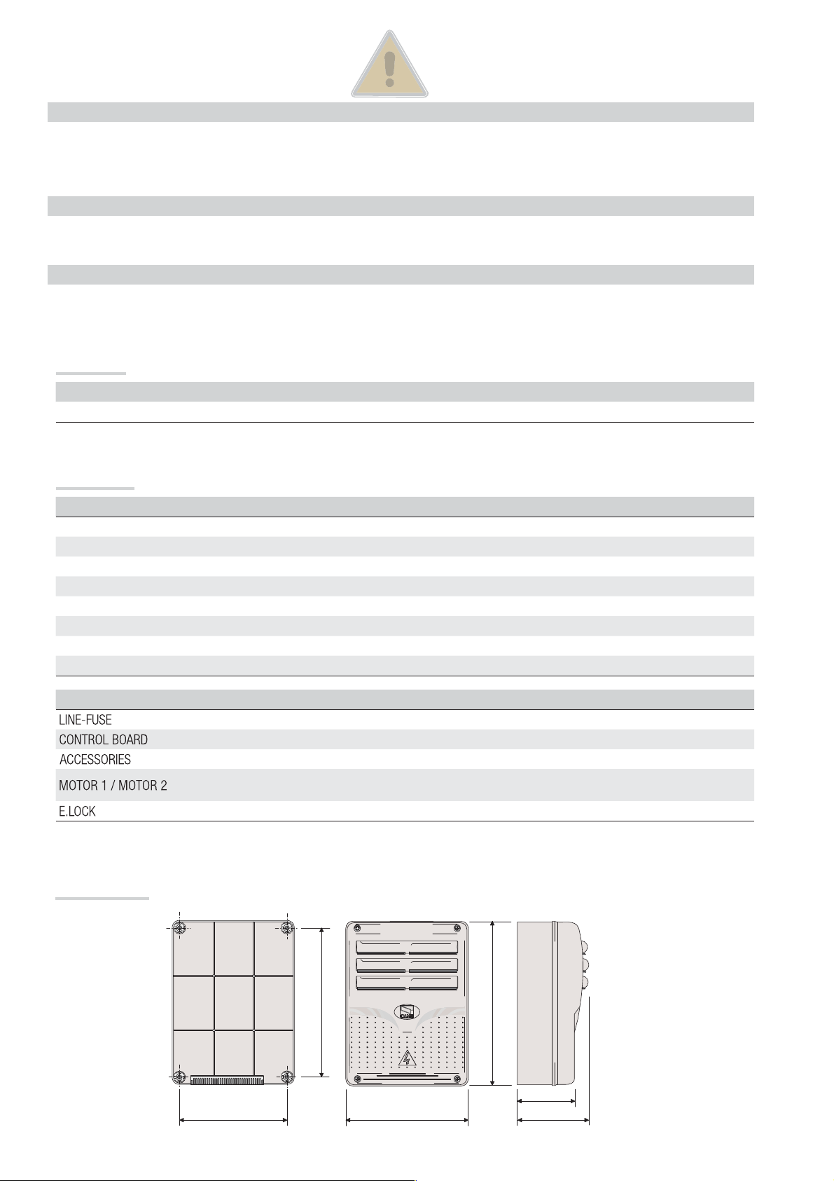
Dimensions (mm)
1- 03/2016 - © Came S.p.A. - The manual's contents may be edited at any time without notice.
FA00044-EN v.
2 - Manual code:
p.
Page 3
3
FA00 044-EN
1
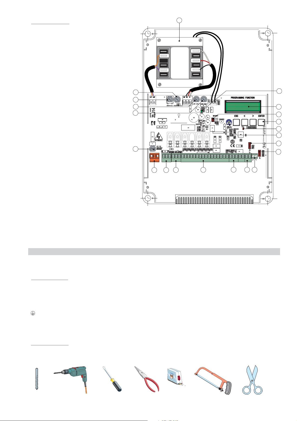
Description of parts
1. Transformer
2. Power supply on warning LED
3. Display
4. Memory roll board connector
5. Programming buttons
6. Programming warning LED
7. Display brightness adjusting trimmer
8. Connector for the R700 card
9. AF card connector
10. Antenna terminal
11. Terminals for transponder
12. Endstop terminals
13. Terminals for control and safety devices
14. Encoder terminals
15. Terminals for gearmotors
16. Power supply terminals
17. Line fuse
18. Control-board fuse
19. Electric-lock fuse
20. Motor fuse
21. Accessories fuse
21
20
19
18
17
L N
120V=3,15A-F
230V=1,6A-F
1
0V
0
17V
26V
230V
24 12 0L1T L2T
+ E - M N ENC
10 11 TS E E3 ES 1 2 3 3P 4 5 7 CX CY CZ
2
3
4
5
6
7
8
9
B1 B2 2 FA FC S1 GND
14
1516
13
101112
GENERAL INSTRUCTIONS FOR INSTALLING
Only skilled, qualified staff must install this product.
⚠
Before working on the control panel, cut off the main current supply and, if present, remove any batteries.
⚠
Preliminary checks
Before installing the control panel it is necessary to:
⚠
• make sure that the point where the control panel is fastened is protected from any impacts and that the anchoring surface is solid enough, and
that proper tools are used (that is, screws, anchors, and so on); • make sure you have set up a suitable dual pole cut off device along the power
supply that is compliant with the installation rules. It should completely cut off the power supply according to category III surcharge conditions
(that is, with minimum contact openings of 3 mm);
•
Make sure that any connections inside the container (ones that ensure continuity to the protection circuit) are fitted with additional insulation
with respect to those of other electrical parts inside.
Tools and materials
Make sure you have all the tools and materials you will need for installing in total safety and in compliance with applicable regulations. The figure
1- 03/2016 - © Came S.p.A. - The manual's contents may be edited at any time without notice.
shows some of the equipment installers will need.
FA00044-EN v.
3 - Manual code:
p.
Page 4
4
FA00 044-EN
1
Cable types and minimum thicknesses
Connection Cable type
Cable length
1 < 15 m
230 V AC power-supply to control panel H05RN-F 3G x 1.5 mm
Encoder gearmotor power supply*
3 x 1.5 mm
Power supply to gearmotor** 2 x 1.5 mm
Flashing light 2 x 0.5 mm
Photocell transmitters 2 x 0.5 mm
Photocell receivers 4 x 0.5 mm
FROR CEI 20-22
CEI EN
50267-2-1
Command and safety device 2 x 0.5 mm
Endstop*** 3 x 1.5 mm
2
2
2
Cable length
15 < 30 m
3G x 2.5 mm
3 x 2.5 mm
2 x 2.5 mm
2
2
2
2
2
2
2
2
Antenna the RG58 antenna max 10 m
Encoder**** 2402C 22AWG max 30 m
* AXO ** FROG-A24, F4024, F1024, FROG-A24E, F7024E *** FROG-A24, F4024, F1024 **** FROG-A24E, F7024E, F4024E
If cable lengths di er from those specifi ed in the table, establish the cable sections depending on the actual power draw of the connected
devices and according to the provisions of regulation CEI EN 60204-1.
For multiple, sequential loads along the same line, the dimensions on the table need to be recalculated according to the actual power draw and
distances. For connecting products that are not contemplated in this manual, see the literature accompanying said products
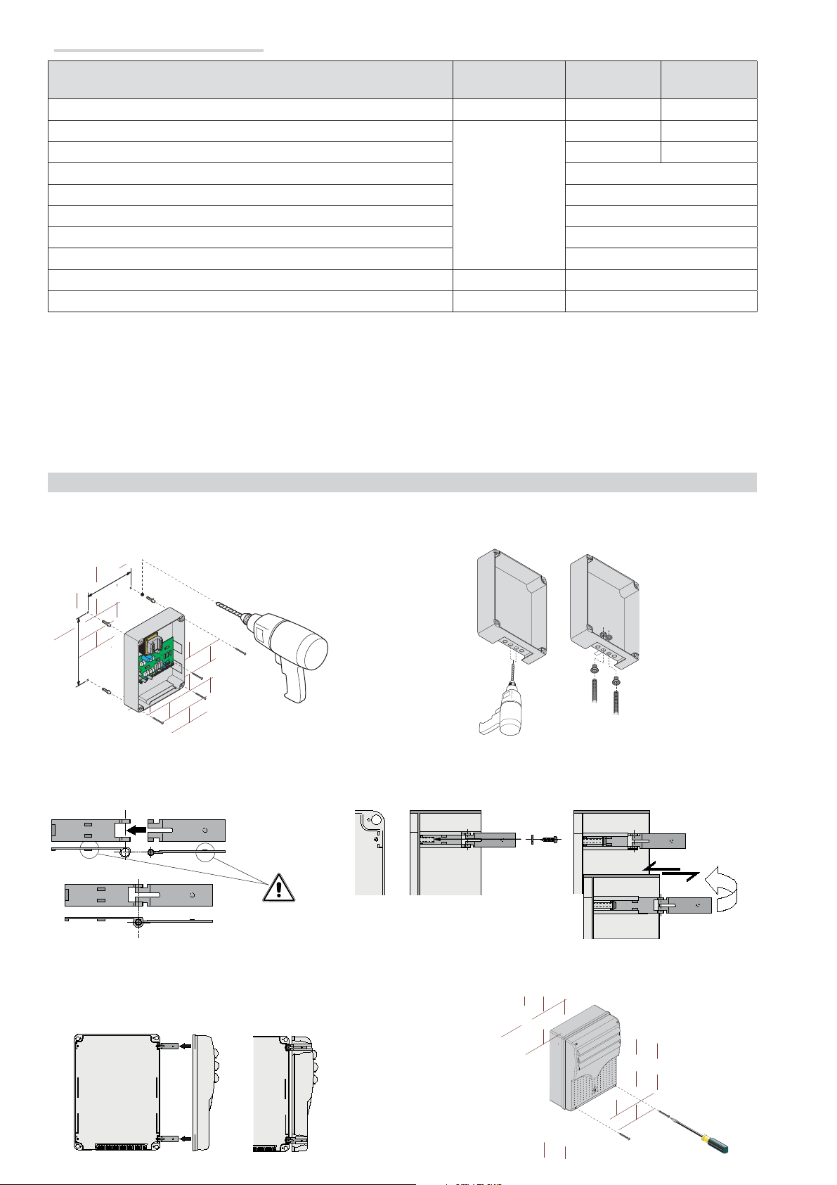
INSTALLATION
Fasten the control panel in a protected area using suitable screws. anchors and braces.
Drill through the pre-perforated holes and fit the cable gland with corrugated pipes for passing through the electric cables.
Pre-perforated hole diameter: 20 mm.
Assemble the pressure hinges.
Fit the hinges into the box (either on the right or left) and fasten them using the supplied screws and washers.
slide to rotate
15 mm~
Snap the cover onto the hinges. Close it and secure it using the supplied screws.
After performing the settings and adjustments, fasten the cover using the supplied screws.
1- 03/2016 - © Came S.p.A. - The manual's contents may be edited at any time without notice.
FA00044-EN v.
4 - Manual code:
p.
Page 5
5
FA00 044-EN
1
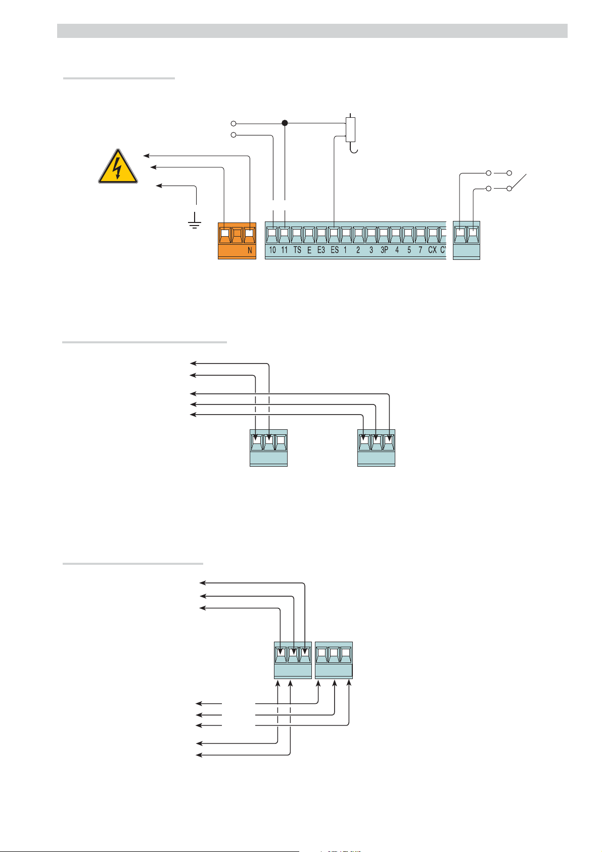
ELECTRICAL CONNECTIONS
Power supply to accessories
Terminals for powering the 24 V AC/DC
accessories Maximum power: 50 W
Electric-lock connection
rated at 12 V - 15 W max
Possible output of the
second radio-receiver
channel (NO contact).
Contact rated for:
500 mA - 24 V DC.
230 V AC - 50/60 Hz
Connecting the gearmotors with endstops
N
M
24 V DC gearmotor
FC
FA
F
+ -
L
MNENC 2FAFC
" "
Connecting the encoder gearmotors
24 V DC gearmotor
1- 03/2016 - © Came S.p.A. - The manual's contents may be edited at any time without notice.
FA00044-EN v.
5 - Manual code:
p.
E
N
M
MNENC +E-
+
E
-
White
Brown
Green
M
N
Page 6
CY
6
FA00 044-EN
1
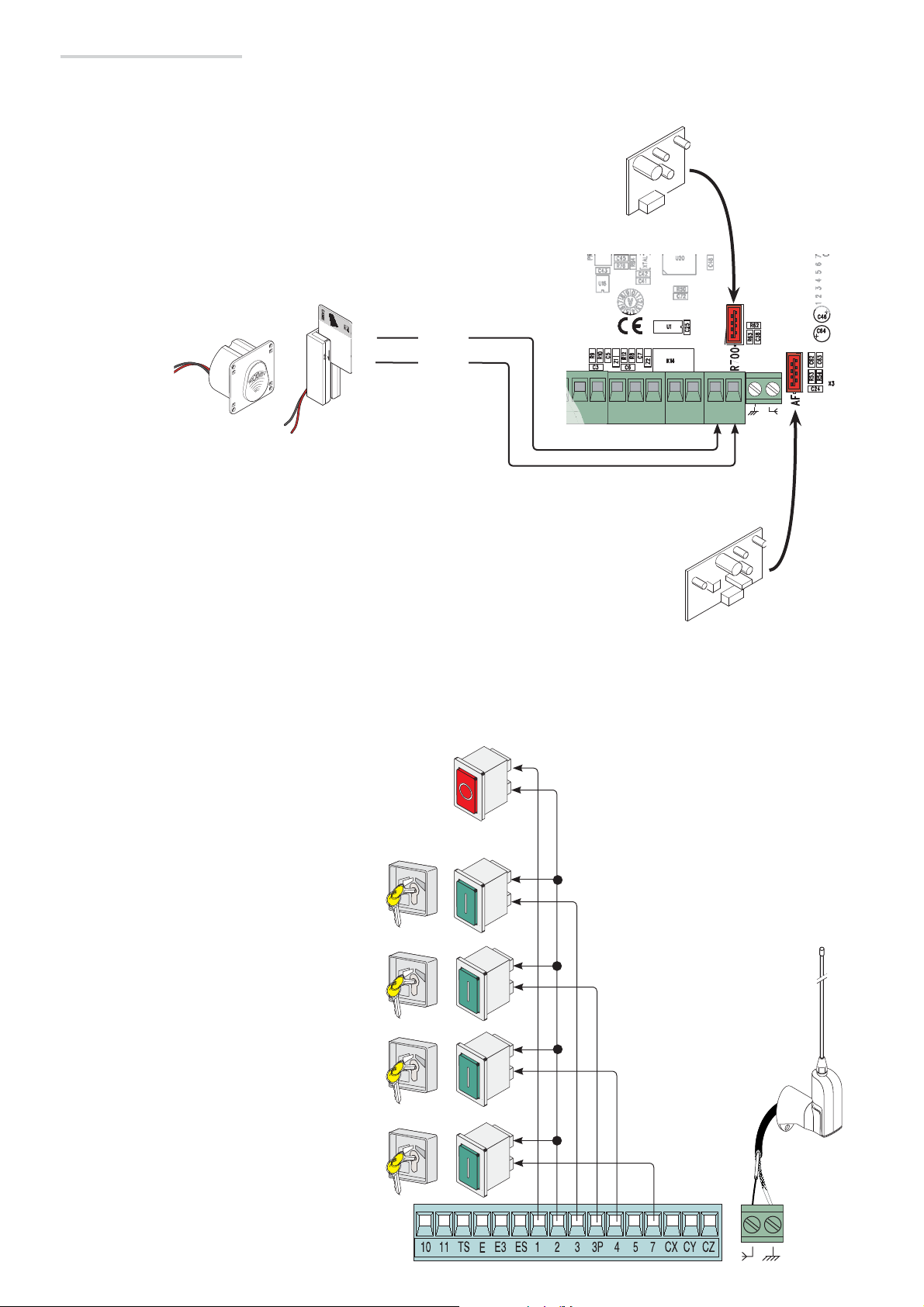
Command and control devices
Command and control devices
Before fitting any snap-in cards (such as the AF or R700), YOU MUST CUT OFF THE POWER MAINS, and disconnect the power
⚠
mains.
Transponder or
card reader
Fit the R700 decoding card for recognition of the TSP00
sensor or the LT001 card reader.
ACCESS CONTROL
Red
Black
CAME
CY CZ
Fit the AF card to control the operator
via transmitter.
R700
B1 B2 2 FA FC S1 GND
AF
Stop button (NC contact). For stopping the gate leaves while excluding
automatic closing. To resume movement press the control button or
use another control device.
If unused, select [Disabled] from the [Total Stop] in the
[FUNCTIONS].
OPEN ONLY function from control device with NO
contact.
PARTIAL OPENING feature from command device (NO
contact).
See the [Partial open] function, for opening times in the
[SET TIMES] menu.
ONLY CLOSE function from control device (NO
contact).
OPEN-STOP-CLOSE-STOP sequential function /
OPEN-CLOSE-INVERT step-step from a control
device (NO contact).
See the [2-7 command] in the [FUNCTIONS].
Antenna with RG58 cable
1- 03/2016 - © Came S.p.A. - The manual's contents may be edited at any time without notice.
FA00044-EN v.
6 - Manual code:
p.
Page 7

7
FA00 044-EN
1
Signaling devices
Signaling devices
Courtesy light (contact rated for: 24 V - 25 W max).
Auxiliary connection of an outdoor light which can be positioned
where you like, to increase lighting in the driveway/parking area.
It stays on for a settable time.
See the [Courtesy Time] function in the [SET TIMES] menu.
Flashing light or cycle light
(contact rated for: 24 V - 25 W max).
Flashing light: it flashes during the gate's opening and
closing phases.
Cycle light: it stays on from the moment the leaf starts
opening until it again closes completely (including the
automatic-closing time)
See the [Light E] in the [FUNCTIONS].
Gate open warning light (Contact rated for:
24 V - 3 W max).
To warn that the gate is open.
It switches o when the gate is closed.
CAME
Safety devices
Photocells
Configure contact CX, CY or CZ (NC), input for EN 12978
safety devices like photocells.
See [CX input], [CY input] or [CZ input].
- C1 reopening during closing. When the leaf is closing,
opening the contact causes the leaf to invert its direction of
movement until it is completely open;
- C2 closing during opening. When the leaf is opening ,
opening the contact causes the leaf to invert its direction of
movement until it is completely closed;
- C3 partial stop. Leaf stops, if it is moving, and sets up for
automatic closing (if the automatic closing function has been
activated;
- C4 obstruction wait. Leaf stops, if it is moving, and starts
back again once the obstruction is removed.
If unused, contacts CX, CY and CZ should be disabled
during programming.
RX
DIR DELTA-S
RX TX
./
#.#
DELTA
TX
Sensitive Safety Edges
Configure contact CX, CY or CZ (NC), input for EN 12978
safety devices such as sensitive safety-edges.
See [CX input], [CY input] or [CZ input].
- C7 reopening during closing. When the leaf is closing,
opening the contact causes the leaf to invert its direction
of movement until it is completely open;
- C8 reclosing during opening. When the leaf is opening,
opening the contact, causes it to invert its movement
1- 03/2016 - © Came S.p.A. - The manual's contents may be edited at any time without notice.
until it is completely closed.
If unused, contacts CX, CY and CZ should be
disabled during programming.
FA00044-EN v.
7 - Manual code:
p.
DFW
DFW with control
board of the DFI
connections
Page 8

8
FA00 044-EN
1
Connecting the safety devices (i.e. the safety test)
At each opening or closing command, the card checks the efficiency of the safety devices, such as photocells). Any anomalies will inhibit all
commands.
Select from the [Safety Test] which of inputs CX, CY or CZ to turn on.
FUSIBILE 200m A
+
C
10 2 T X
-
DELTA
+
N.O.
C.
N.C.
+
-
+
NC
DIR /
TX 2
TX
2
DELTA S
-
-
1- 03/2016 - © Came S.p.A. - The manual's contents may be edited at any time without notice.
FA00044-EN v.
8 - Manual code:
p.
Page 9

9
FA00 044-EN
1
PROGRAMMING
PROGRAMMING
Description of programming commands
the <-----> signs on the display are for:
- showing the currently selected item
{
The ESC button is for:
- exiting menus;
- cancelling changes.
The < > keys are for:
- moving from one item to another;
- increasing or decreasing values.
To enter the menu, keep the ENTER
button pressed for at least one
second.
To select menu items,
use the arrow keys ...
{
{
The ENTER key is for:
- entering menus;
{
- confirming or memorizing set values.
LANGUAGE
< English >
FUNCTIONS
Imp. Run
.. then press ENTER
< TIMING ADJ >
also for the submenus,
use the arrow keys to
select ...
If the < > arrows are set to the
Cycle Time
< 90s. >
1- 03/2016 - © Came S.p.A. - The manual's contents may be edited at any time without notice.
Cycle Time
< 100s. >
[Cycle time], you may edit their
value.
... the press ENTER to confirm ...
< A.C.T. >
< Cycle Time >
90s.
... to exit the menu wait 30
seconds, or press ESC, until the
start up screen appears.
.. then press ENTER
To increase or reduce the value
use the arrows...
FA00044-EN v.
9 - Manual code:
p.
Page 10

10
FA00 044-EN
1
Meaning of the menu items abbreviations
[Travel sens] Gate Run Sensibility
[Partial open] Partial Opening
[Maint Action] Maintained Action
[Auto Close] Automatic Closing
[Config
]
Configuration
[Assoc Function] Associated Function
[Set Travel] Set gate-leaf Travel
[
Open Accel]
[Close
[
Opn Slw Dwn]
[Cls
Opening Soft-Stop as a percentage
Accel]
Closing Soft-Stop as a percentage
Opening Slow Down as a percentage
Slw Dwn]
Closing Slow Down as a percentage
[Change Code] Mod. name
[Start message] Starting message
[Soft Start] Slowed-down Start
[Enc Slow Down] Opening and closing slow-downs with ENCODER
[Obstruc Detct
]
Obstruction Detection
[Delete user] Remove User
[Amper. Sens.] Amperometric Sensitivity
[Travel sens] Travel Sensitivity
[Slw Dwn sens] Sensitivity of Slow Downs
[Closing thrust] Closing thrust
[Ram jolt
time]
Ram-jolt Time
[Preflash time] Preflashing Time
[Slow down
time]
Slow-down Time
[Lock time] Lock Time
[ACT] Automatic Closing Time
[
PartialACT]
[Slow dwn s
peed]
Slow-down Speed
Partial Automatic Closing Time
[Travel rate %] Gate-leaf Travel Speed
Menu map
[LANGUAGE] Default
[Italiano] / [English] / [Français] / [Deutsch] / [Español] / [Portugues euro]/[Portugues bras]
English
[FUNCTIONS] Default
[Auto Close] [Disabled] / [Enabled] [Enabled]
[Maint Action] [Disabled] / [Enabled] / [Closing] [Disabled]
[Obstruc Detct] [Disabled] / [Enabled] [Disabled]
[Safety Test] [Disabled] / [CX] / [CY] / [CZ] / [CX+CY] / [CX+CZ] / [CY+CZ] / [CX+CY+CZ] [Disabled]
[Preflashing] [Disabled] / [Enabled] [Disabled]
[Ram Jolt] [Disabled] / [Closing] / [Opening] / [Open-Close] [Disabled]
[Total Stop] [Disabled] / [Enabled] [Enabled]
[CX input] [Disabled] / [C1] / [C2] / [C2] / [C4] / [C7] / [C8] [C1]
[CY input] [Disabled] / [C1] / [C2] / [C2] / [C4] / [C7] / [C8] [C3]
[CZ input] [Disabled] / [C1] / [C2] / [C2] / [C4] / [C7] / [C8] [C2]
[Closing thrust] [Disabled] / [Enabled] [Disabled]
[Lock] [Disabled] / [Closing] / [Opening] / [Open-Close] [Closing]
[LockType] [Pulsed] / [Continuous] [Pulsed]
[Config] [Time Lmt Swtch] / [End Stop] / [Slow Down] / [Op LS-Cl Sl Dn] / [ENCODER] [ENCODER]
[End Stop] [N.C. / N.O.] [N.C.]
[2-7 command] [Open-Close] / [Opn Stp Clse] [Open-Close]
[Light E] [Flashing light] / [Courtesy] / [Cycle] [Flashing light]
[B1-B2 output] [Bistable] / [Monostable] [Monostable]
[IMP. TRAVEL] Default
[Motor type] [FROG-F4024E] / [FROG J] / [FROG-FL] / [AMICO] / [MYTO] / [AXO] / [FAST] / [FERNI] [FROG-F4024E]
[Travel rate %] [20%]
⇨
[100%] [100%]
[Slow dwn speed] [5%] ⇨ [80%] [50%]
[Soft Start] [Enabled] / [Disabled] [Disabled]
[Amper. Sens.]* [Enabled] / [Disabled] [Enabled]
[Travel sens]* [
-◦+
[Slow downtime]** [0 s] ⇨ [30 s] [20 s]
*This function does not appear if [ENCODER] from the [Config].
**This function only appears if [Slow Down]or [Op LS-Cl Sl Dn] from the [Config].
1- 03/2016 - © Came S.p.A. - The manual's contents may be edited at any time without notice.
FA00044-EN v.
]
10 - Manual code:
p.
Page 11

11
FA00 044-EN
1
[ENCODER] Default
[Sensibility] [Enabled] / [Disabled] [Enabled]
[Travel sens] [
[Slw Dwnsens] [
-◦+
-◦+
[Enc Slow Down] [ON] / [OFF] [ON]
[
Opn Slw Dwn]
[C
ls SlwDwn
[C
Close Accel]
[
OpenAccel]
[1%] ⇨ [40%] [10%]
] [1%] ⇨ [40%] [10%]
[1%] ⇨ [15%] [15%]
[1%] ⇨ [15%] [15%]
[Travel calibr] [Confirm? (No)] / [Confirm? (Yes)]
SET TIMES Default
[ACT] [0 s]
[
PartialACT]
[0 s]
⇨
[300 s] [10 s]
⇨
[300 s] [10 s]
[Cycle time] [10 s] ⇨[150 s] [90 s]
[Preflash time] [1 s] ⇨ [60 s] [5 s]
[Lock time] [1 s] ⇨ [5 s] [2 s]
[Ram jolt time] [1 s]
⇨
[3 s] [1 s]
[Partial open] [5 s] ⇨ [60 s] [10 s]
[Courtesy Time] [1 s] ⇨ [300 s] [300 s]
[USERS]
[Add User] (250 max)
[Change Name]
[Change Code]
[Assoc Function] [2-7] / [Open] / [B1-B2] / [2-3P] / [Disabled];
[Delete user]
[Delete ALL] [Confirm? (No)] / [Confirm? (Yes)]
[Save memory] [Confirm? (No)] / [Confirm? (Yes)]
[Load memory] [Confirm? (No)] / [Confirm? (Yes)]
]
]
[INFO]
[Version] / [No. of travels] / [Start message] / [Reset system]
[MOTORS TEST]
[OPEN =>]
IMPORTANT! Start programming by performing the first function, that is, [MOTOR TYPE], [TOTAL STOP] and [TRAVEL
CALIBR]
.
Language menu
[LANGUAGE]
[Italiano] / [English] / [Français] / [Deutsch] / [Español] / [Portugues euro] / [Portugues bras]
Select one of the available languages
Functions menu
[FUNCTIONS]
1- 03/2016 - © Came S.p.A. - The manual's contents may be edited at any time without notice.
[Auto Close] [Disabled] / [Enabled]
The fi rst automatic-closing wait starts when the opening endstop point is reached and can be set to between 0 and 300 s. The automatic
closing does not turn on if any of the safety devices trigger when an obstruction is detected, after a total stop or during a power outage.
FA00044-EN v.
[Maint Action] [Disabled] / [Enabled] / [Closing]
The leaf opens and closes by keeping a button pressed. Opening button on contact 2-3 and closing button on contact 2-4. All other control
devices, even radio-based ones, are excluded.
11 - Manual code:
p.
Page 12

12
FA00 044-EN
1
[Obstruc Detct] [Disabled] / [Enabled]
With the leaf closed, open or after a total stop, the operator remains idle if the safety devices, like photocells or sensitive safety-edges)
detect and obstruction.
[Safety Test]
After every opening or closing command, the board will check whether the photocells are working properly
[Disabled] / [CX] / [CY] / [CZ] / [CX+CY] / [CX+CZ] / [CY+CZ] / [CX+CY+CZ]
.
[Prefl ashing] [Disabled] / [Enabled]
After an opening or closing command, the fl ashing light connected to 10-E, fl ashes before the maneuver starts.
To set the time, see
[Preflash time]
in the
SET TIMES menu
.
[Ram Jolt] [Disabled] / [Closing] / [Opening] / [Open-Close]
Before each opening and closing, the gate-leaf gives a fi nal thrust to assist the electric-lock release. To adjust the thrust time, select
jolt time]
in the
SET TIMES menu
.
[Ram
[Total Stop] [Enabled] / [Disabled]
NC input - Leaf stop while excluding any automatic closing; to resume movement, use the control device. The safety device is inserted into
[1-2].
[CX input] [Disabled] / [C1] / [C2] / [C3] / [C4] / [C7] / [C8]
NC input – Can associate: C1 = reopening during closing by photocells, C2 = reclosing during opening by photocells, C3 = partial stop, C4
= obstruction wait, C7 = reopening during closing by sensitive safety-edges, C8 = reclosing during opening by sensitive safety-edges.
[CY input] [Disabled] / [C1] / [C2] / [C3] / [C4] / [C7] / [C8]
NC input – Can associate: C1 = reopening during closing by photocells, C2 = reclosing during opening by photocells, C3 = partial stop, C4
= obstruction wait, C7 = reopening during closing by sensitive safety-edges, C8 = reclosing during opening by sensitive safety-edges.
[CZ input] [Disabled] / [C1] / [C2] / [C3] / [C4] / [C7] / [C8]
NC input – Can associate: C1 = reopening during closing by photocells, C2 = reclosing during opening by photocells, C3 = partial stop, C4
= obstruction wait, C7 = reopening during closing by sensitive safety-edges, C8 = reclosing during opening by sensitive safety-edges.
[Closing thrust] [Disabled] / [Enabled]
At each closing endstop, the operator thrusts the fi nal closing of the leaf for a a few seconds.
[Lock]
[Disabled] / [Closing] / [Opening] / [Open-Close]
Set the electric lock to lock the leaves,
by choosing among one of the available choices.
[Lock Type] [Pulsed] / [Continuous]
Setting the type of electric lock:
- impulse electric lock - it activates for a few seconds when the gate is either open or closed. The activation time is adjusted by the[Lock
time] function
- continuous electric lock - it activates during the entire opening or closing maneuver.
[Confi g]
[Slow Down] / [Op LS-Cl Sl Dn] / [ENCODER] / [Time Lmt Swtch] / [End Stop]
Configuring the opening and closing slow-downs
[Slow Down]*
[Lsop-Clos. Slw]
[ENCODER]
[Time Lmt Swtch]
[End Stop]
➡opening and closing slow-downs.
*
➡opening endstop and closing slow-down.
➡slow-down management, obstruction detection and sensitivity.
➡timed endstop.
➡opening and closing endstop.
* slowdowns configurable with the [Slow down time] in the [Set Travel]
[End Stop] [N.C] / [N.O]
Configuring the endstops as normally opened or closed contacts.
This function only appears if option is selected between
[End Stop], [Lsop-Clos. Slw]
or
[Slow Down]
from the
[Confi g] function
.
[2-7 command] [Open-Close] / [Opn Stp Clse]
Configuration contact 2-7 in step-step (open-close) or sequential (open-stop-close-stop).
[Light E] [Cycle] / [Flashing light]
Configuring the light connected to 10-E:
- cycle: freely positionable outdoor light for increasing lighting in the driveway/parking area. It stays lit from the moment that the gate leaf
starts opening until it is completely closed (including the automatic closing time). In case the automatic closing is off, it stays on only during
the gate-leaves' movement.
- flashing: to alert when the moving leaf is either closing or opening.
[B1-B2 output] [Monostable] / [Bistable]
Configuring contact B1-B2 in Monostable or Bistable mode (switch).
1- 03/2016 - © Came S.p.A. - The manual's contents may be edited at any time without notice.
FA00044-EN v.
12 - Manual code:
p.
Page 13

13
FA00 044-EN
1
Gate run setting menu
[Set Travel]
[Motor type] [FROG-F4024E] / [FROG-J] / [FROG-FL] / [AMICO] / [MYTO] / [AXO] / [FAST] / [FERNI] / [ATI]
Setting the type of operator installed in the system.
⇨
[Travel rate %] [50%]
[100%]
Adjusting the maneuvering speed, calculated as a percentage.
[Slow dwn speed] [10%] ⇨ [50%]
Adjusting the slow-down speed, calculated as a percentage.
[Soft Start] [Disabled] / [Enabled]
After each opening and closing command, the leaves start at slowed down speed for a few seconds.
[Amper. Sens.] [Disabled] / [Enabled]
Obstruction detection sensibility.
This function does not appear if [Encoder] is set in the [Config] function.
When an obstruction is met the function intervenes in the following way:
- [Time Lmt Swtch]it stops the gate leaves during a maneuver;
- [End Stop] it inverts the gate leaves during a maneuver;
- [Slow Down] it inverts the gate leaf movement during a maneuver and stop the movement during a slow down.
- [Lsop-Clos. Slw] it inverts the gate leaves during a maneuver and stops them only during the closing slow-down.
When the function is disabled, it stops the gate leaves when the maximum voltage threshold is exceeded.
[Travel sens]
[
-◦+
]
Adjusting the Amperometric sensibility.
You need to turn on the [Amper. Sens.] in the [Set Travel].
[Slow down time] [OFF] ⇨ [30 s]
Slow-down time of the gate leaves before every endstop. The time can be set to between zero and 30 s.
This function only appears if the [Slow Down] or [Lsop-Clos. Slw] from the [Config] function.
ENCODER menu
The [ENCODER] menu appears only when the [Config] in the [FUNCTIONS] menu.
[ENCODER] menu
[Sensitivity] [Enabled] / [Disabled]
Obstruction detection sensibility.
[Travel sens] [
-◦+
]
Obstruction detection sensitivity during gate run (both opening and closing).
You need to turn on the [Sensitivity] in the [ENCODER] menu.
[Slw Dwn sens] [
-◦+
]
Obstruction detection sensitivity during slow-down (both opening and closing).
You need to turn on the [Sensitivity] in the [ENCODER] menu.
[Enc Slow Down] [ON] / [OFF]
Activating the opening and closing slow-down starting points.
[Opn Slw Dwn] [1%] ⇨ [40%]
Adjusting the starting slow-down point before the opening endstop.
The starting slow-down point is calculated as a percentage ( from 1% to 40% of the complete leaf-travel).
This function only appears if the [Enc Slow Down] in the [ENCODER] menu.
1- 03/2016 - © Came S.p.A. - The manual's contents may be edited at any time without notice.
[Cls Slw Dwn [1%] ⇨ [40%]
Adjusting the starting slow-down point before the closing endstop.
The starting slow-down point is calculated as a percentage ( from 1% to 40% of the complete leaf-travel).
FA00044-EN v.
This function only appears if the [Enc Slow Down] in the [ENCODER] menu.
[Close Accel] [1%] ⇨ [15%]
Adjusting the soft-spot starting point calculated as a percentage (from 1% to 15% of the complete travel) before the closing endstop point.
13 - Manual code:
p.
Page 14

14
FA00 044-EN
1
[Open Accel] [1%] ⇨ [15%]
Adjusting the soft-spot starting point as a percentage (from 1% to 15% of the complete travel) before the opening endstop point.
[Travel calibr]
Automatic calibration of the gate-leaf run (see the TRAVEL CALIBRATION paragraph)
Time settings menu
SET TIMES
[ACT] [0 s] ⇨ [300 s]
The fi rst automatic-closing wait starts when the opening endstop point is reached and can be set to between 0 and 300 s. The automatic
closing does not turn on if any of the safety devices trigger when an obstruction is detected, after a total stop or during a power outage.
[Partial ACT] [0 s] ⇨ [300 s]
Leaf waiting-time when open, after a partial close command. Once this time elapses, a closing maneuver is automatically performed. The
waiting time can be set to between 0 and 300 seconds.
[Cycle time] [10 s]
⇨
[150 s]
Gearmotor working time during opening and closing. The working time can be set to between 10 and 150 seconds.
[Prefl ash time] [1 s]
⇨
[60 s]
After an opening or closing command, the flashing light connected on 10-E, flashes between one and sixty seconds before starting the
maneuver.
[Lock time] [1 s]
⇨
[5 s]
Intervention time for the electrolock to release after each opening command. The intervention time can be adjusted to between one second
and fi ve seconds.
[Ram jolt time] [1 s] ⇨ [3 s]
The closing and opening jolt thrust-time of the geartmotors after each command. The thrust time can be set to between one and three
seconds.
[Partial open]
[5 s]
⇨
[60 s]
Leaf opening time. The time can set between 5 s and 60 s.
[Courtesy Time] [60 s] ⇨ [300 s]
Supplementary light. It stays on for the time needed during the gate's opening or closing maneuvers.
contact output [10-E3]. It is adjustable between 60 s and 300 s.
Users Menu
Users Menu
[USERS]
[USERS]
[Add User]
Entering up to 250 users and associating to each one a function of choice among those included. The entering must be done via transmitter or other control device (see ENTERING NEW USERS).
[Change Name]
To change the number or name of users
[Change Code]
To modify the command code that is associated to a user.
[Assoc Function]
[
2-7]
[Open]
[2-3P]
[B1-B2]
➡
Step-step command (open-close) or sequential command (open-stop-close-stop)
➡
Open only command
➡
Pedestrian or partial opening
➡
Contact B1-B2 output
[Delete user]
To remove a user. Confirm removal with ENTER.
[Delete ALL]
To remove all users. Confirm removal with ENTER.
1- 03/2016 - © Came S.p.A. - The manual's contents may be edited at any time without notice.
FA00044-EN v.
14 - Manual code:
p.
Page 15

15
FA00 044-EN
1
[Save memory]
To save system users and settings in memory roll. Confirm saving with ENTER.
[Load memory]
For uploading the data saved in the memory roll onto the electronic board.
If the boards feature different versions, you may only upload the users.
Info menu
[INFO]
[Version]
View software version.
[No. of travels]
View the number of completed maneuvers.
[Start message]
View opening message. To edit the text, press ENTER. Use ENTER to move the cursor forward, ESC for moving the cursor backward and <
> to select the letter of figure. Confirm text by pressing the ENTER key for some seconds.
[Reset system]
To restore the initial settings. Press ENTER to confirm the Reset.
Motors Test menu
[MOTORS TEST]
[OPEN =>]
For checking the proper rotation direction of the gearmotors.
Keep the < key pressed for some seconds and check that the leaf actually opens. If the rotation direction is wrong, invert the motor's
phases.
1- 03/2016 - © Came S.p.A. - The manual's contents may be edited at any time without notice.
FA00044-EN v.
15 - Manual code:
p.
Page 16

16
FA00 044-EN
1
Entering a new user
1. From the
[USERS], select
[Add User]. Press
ENTER to confirm.
< Add User >
2. Select [Confirm?
(Yes)] and press
ENTER to confirm.
Add User
<Confirm?(yes)>
3. Select the function
to associate to users.
Press ENTER to
confirm...
5. Once the code
is entered, the user
number will appear
with the memorized
number ...
Modify user name
Assoc Function
< 2-7 >
--001-Radio
4. ... a code to enter will
be requested.
Send the code from
the transmitter, with
the swipe card or
transponder.
6. ... or, if the code is
already entered, then
[Existing code].
Wait for code
>>>>>>
ACCESS CONTROL
Existing code
001: --U001--
1. From the
[USERS], select
[Change Name].
Press ENTER to
confirm
3. Use ENTER to move
the cursor forward,
ESC for moving the
cursor backward and
< > to select the
letter of figure.
< Change Name >
Change Name
--001--
2. Select the user
number or name to edit
and press ENTER to
confirm.
4. Press ENTER for a
few seconds to confirm
the text.
Select user
< 001: --U001-- >
Change Name
JOHN----
1- 03/2016 - © Came S.p.A. - The manual's contents may be edited at any time without notice.
FA00044-EN v.
16 - Manual code:
p.
Page 17

17
FA00 044-EN
1
Modify code
1. From the
[USERS], select
[Change Code].
Press ENTER to
confirm
3. ... a code to enter
will be requested.
Send the code from
the transmitter, with
the swipe card or
transponder.
< Change Code >
Wait for code
>>>>>>
ACCESS CONTROL
2. Select the user name
of which you want to
edit the code and press
ENTER to confirm.
4. ... once the code
is entered, the user
number and type of
memorized command
will appear...
Change Code
Change Code
< 002: --U002-- >
002
Radio
Function related to the user
1. From the
[USERS], select
[Assoc Function].
Press ENTER to
confirm
3. Select the new
function to relate to
the user. Press ENTER
to confirm.
1- 03/2016 - © Came S.p.A. - The manual's contents may be edited at any time without notice.
<Assoc Function>
Assoc Function
Assoc Function
< 2-7 >
5. Select [Confirm?
(Yes)] and press ENTER
to confirm.
2. Select the user
name for which you
want to change the
function and press
ENTER to confirm.
4. Select [Confirm?
(Yes)] and press ENTER
to confirm.
Change Code
<Confirm?(yes)>
Select user
Select user
< 002: --U002-- >
Assoc Function
<Confirm?(yes)>
FA00044-EN v.
17 - M anual code:
p.
Page 18

18
FA00 044-EN
1
Travel calibration
Before calibrating the gate run, check that the maneuvering area is free from any obstruction and that there are both opening and
⚠
closing mechanical stops.
The mechanical end-stops are obligatory.
⚠
Important! During the calibration, all safety devices will be disabled except for the PARTIAL STOP one.
1. From the [ENCODER]
menu, select [Travel
calibr]. Press ENTER to
confirm
3. The gate-leaf will close
until the final strike-point ...
<Travel calibr>
Travel calibr
Close
2. Select [Confirm?
(Yes)] and press
ENTER to confirm.
4. ... then, the gate-
leaf, will open until the
final strike-point.
Travel calibr
Travel calibr
<Confirm?(yes)>
Travel calibr
Open
5. Once the procedure is
over, the display will show
[Travel calibr OK] for a few
seconds.
Memory Roll Card
For memorizing user and system configuration data, then using them on another control board.
After memorizing the data, it is best to remove the Memory Roll card while the control board is in operation.
ERROR MESSAGE
Travel calibr
OK
Memory roll
1- 03/2016 - © Came S.p.A. - The manual's contents may be edited at any time without notice.
Error messages appear on the display.
[Encoder - ERROR], [Error!] Broken encoder or wrong connection.
[Safety Test - ERROR] Safety devices malfunctioning.
[End Stop - ERROR] Malfunctioning endstop contacts
[Cycle time - ERROR] Insufficient working time
[Safety - STOP], [C1], [C3], [C4], [C7] or [C8] Malfunctioning safety devices or wrong connection
FA00044-EN v.
18 - Manual code:
p.
Page 19

19
FA00 044-EN
1
DIAGRAM OF THE SLOW-DOWN AND FINAL APPROACH POINTS AND FOR THE ENCODER DEVICE
The run area and slow down and approach points are tested according to the parameters set forth by Technical Standards EN 12455 and
EN 12453 for compliance with the impact forces generated by the running leaves.
D
I
G
B
A
C
F
B
D
E
I
H
A = Normal speed
B* = Slowed-down speed
C = Encoder intervention zone with movement inversion
D = Encoder intervention zone with movement stopped
E = Opening slow-down starting point [OP. SlwDwn%]
F = Closing slow-down starting point [CL. SlwDwn%]
G** = Closing soft-stop starting point [Acc. CL%]
H = Opening soft-stop starting point [Acc. OP%]
I = Final strike-point
* Minimum 600 mm from the strike plate.
** Set the fi nal approach percentage for the function [Acc. CL%] and [Acc. OP%] from the [ENCODER] menu so as to obtain a distance of
between 1 and 50 mm maximum from the fi nal strike plate point.
DISMANTLING AND DISPOSAL
Always make sure you comply with local laws before dismantling and disposing of the product. The packaging materials (cardboard, plastic, and
so on) should be disposed of as solid urban waste, and simply separated from other waste for recycling.
Whereas other components (control boards, batteries, transmitters, and so on) may contain hazardous pollutants. These must therefore be
disposed of by authorized, certified professional services.
DO NOT DISPOSE OF IN NATURE!
1- 03/2016 - © Came S.p.A. - The manual's contents may be edited at any time without notice.
FA00044-EN v.
19 - Manual code:
p.
Page 20

www. came.com
Came S.p.A.
Dos son di Cas ier
Treviso
Sesto al Reghena
Pordenone
Engl is h
FA00 044-EN
1
1 - 03/2016 - © Came S.p. A.
FA00044-EN v.
English - Manual code:
The data and information in this manual may be changed at any time and without notice.
Came S.p.A.
Via Martiri Della Libertà, 15 Via Cornia, 1/b - 1/c
Dosson di Casier
31030
Treviso - Italy
(+39) 0422 4940
(+39) 0422 4941
www. came.com
Sesto al Reghena
33079
Pordenone - Italy
(+39) 0434 698111
(+39) 0434 698434
 Loading...