

Page 1
319V21EN
CONTROL PANEL
FOR 24 V GEARMOTORS
INSTALLATION MANUAL
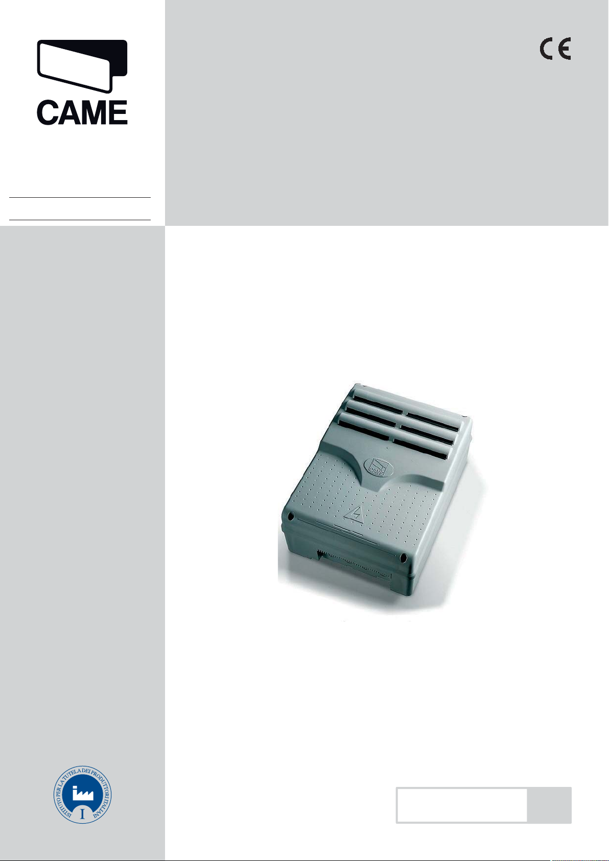
ZL92
English
EN
Page 2
WARNING!
Important instructions for the safety of people:
READ CAREFULLY!
Foreword
• Use of the products must be restricted to its intended use
(i.e. that for which it was expressly built for). Any other use is
to be considered dangerous. Came Cancelli Automatici S.p.A.
ENGLISH
is not liable for any damage resulting from improper, wrongful
or unreasonable use • Keep these warnings with the installation and use manuals issued with the automated system.
Before installing
(preliminary check: in case of a negative
outcome, do not proceed before having
complied with the safety obligations)
• Make sure that the parts you intend to automate are in
good working order, and that they are properly balanced
and aligned. Also, make sure that proper mechanical stops
are already in place • If the operator will be installed at a
height of less than 2.5 m from the ground or other access
level, check whether you will need any protections and/or
warnings • Any gate leaves, fi tted with pedestrian entrances,
onto which you will install an operator, must have a blocking
mechanism when the gate is in motion • Make sure that the
opening of the automated gate is not an entrapment hazard
as regards any surrounding fi xed parts • Do not mount the
operator upside down or onto any elements that may fold
under its weight. If needed, add suitable reinforcements at
the points where it is secured • Do not install onto gates on
either an upward or downward slope (i.e. that are not on fl at,
level ground) • Check that any lawn watering devices will not
wet the gearmotor from the bottom up.
are working properly • Where necessary and in plain sight,
apply the Warning Sings (e.g. gate plate).
Special instructions and
advice for users
• Keep the gate’s area of operation clean and clear of any
obstacles. Trim any vegetation that may interfere with the
photocells • Do not allow children to play with the fi xed command devices, or in the gate’s area of operation. Keep any
remote control devices (i.e. transmitters) away from the children as well • Frequently check the system, to see whether
any anomalies or signs of wear and tear appear on the moving
parts, on the component parts, on the securing points, on the
cables and any accessible connections. Keep any joints (i.e.
hinges) lubricated and clean, and do the same where friction may occur (i.e. slide rails) • Perform functional tests on
photocells and sensitive edges, every six months. Keep glass
panels constantly clean (use a slightly water-moistened cloth;
do not use solvents or any other chemical products) • If the
system requires repairs or modifi cations, release the operator
and do not use it until safety conditions have been restored
• Cut off the power supply before releasing the operator for
manual openings. See instructions • Users are FORBIDDEN
to carry out ANY ACTIONS THAT THEY HAVE NOT BEEN
EXPRESSLY ASKED TO DO OR SO INDICATED in the manuals. Any repairs, modifi cations to the settings and extraordinary maintenance MUST BE DONE BY THE TECHNICAL
ASSISTANCE STAFF • On the periodic maintenance log, note
down the checks you have done.
Installation
• Carefully section off the entire site to prevent unauthorised
access, especially by minors and children • Be careful when
handling operators that weigh more than 20 Kg (see installation manual). In such cases, employ proper weight handling
safety equipment • All opening commands (e.g. buttons, key
selectors, magnetic detectors, etc.) must be installed at least
1.85 m from the gate’s area of operation perimeter - or where
they cannot be reached from the outside of the gate. Also,
the direct commands (e.g. push button, or proximity devices,
etc.) must be installed at a height of at least 1.5 m and must
not be accessible to the public • All ‘maintained action’ commands, must be placed where the moving gate leaves, transit
areas and driveways are completely visible • If missing, apply a permanent label that shows the position of the release
mechanism • Before delivering to the client, verify that the
system is EN 12453 (impact test) standard compliant. Make
sure that the operator has been properly adjusted and that the
safety and protection devices, as well as the manual release
Special instructions and
advice for all
• Avoid working near the hinges or moving mechanical parts
• Stay clear of the gate’s area of operation when in motion •
Do not resist the direction of movement of the gate; this may
present a safety hazard • At all times be extremely careful
about dangerous points that must be indicated by proper
pictograms and/or black and yellow stripes • When using
a selector or command in ‘maintained action’ mode, keep
checking that there are no people in the area of operation of
the moving parts. Do this until you release the command •
The gate may move at any time without warning • Always cut
the power when cleaning performing maintenance.
P. 2 - Manua l code: 319V21E N Vers. 3 04/2017 © CAME cancelli automat ici S.p.A. - The da ta and information in this manu al are subject to change at any ti me without prior notice requi red by Came Cancelli Automatici S. p.A.
Page 3
Legend of symbols
This symbol shows which parts need to be read carefully.
This symbol shows which parts have to do with safety.
This symbol shows what to tell end users.
Intended use and limitations of use
Intended use
The ZL92 control panel is engineered to command 24 V DC operators for swing gates of the STYLO, MYTO, FROG-J and AMICO series.
Any installation and use other than that explained in this manual are forbidden.
Limitations to use
Follow all cable distance and diameter instructions as shown in the table “Cable type and section”
The overall power of the motors must not exceed 300 W.
Description
Engineered and manufactured entirely by CAME Cancelli Automatici S.p.A..
The control panel is powered by 230 V AC, with 50 / 60 Hz frequency. The command devices and accessories work on 24 V. Warning! The accessories must not exceed 50 W overall.
The transformers are fitted with a protection that keep the gate leafs open even when overheating. The leafs are closed only after
the temperature falls below overheating threshold.
All connections are protected by quick fuses, see table.
Functions on the input and output contacts, time adjustments and user management, are all handled via the display and managed
by the software.
It is set up to fit the LB90 card which provides power to the electrical board via emergency batteries, which are in turn automatically
triggered during power outages. When the line current returns, it recharges the batteries.
ENGLISH
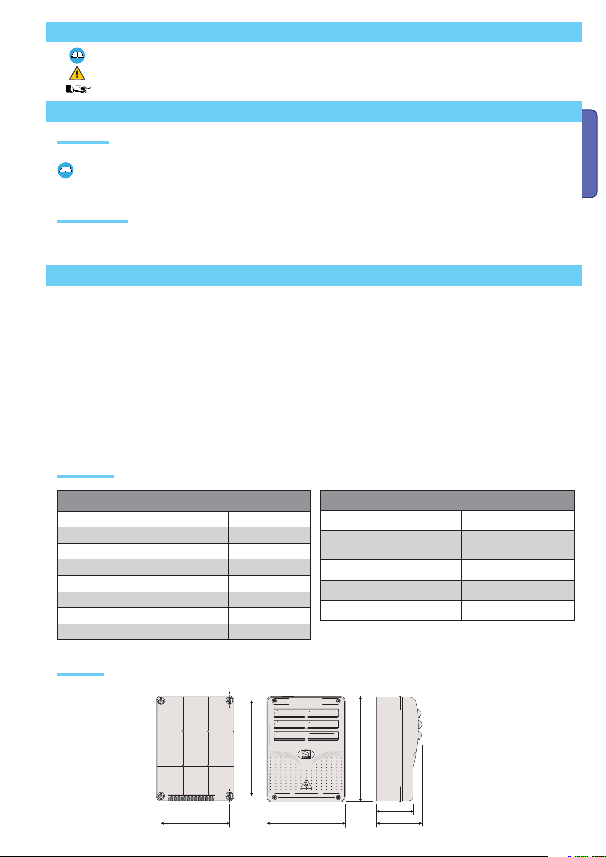
Technical data
TECHNICAL DATA
Power supply 230 V - 50/60 Hz
Maximum rated power 300 W
Power draw when idle 110 mA
Maximum power for 24 V accessories 50 W
Insulation class of the circuits II
Container material ABS
Container protection rating IP54
Working temperature -20 / +55°C
Dimensions
(mm)
FUSE TABLE
to protect: fuse rated to:
Electronic line card 3.15 A-F = 120 V
1.6 A-F = 230 V
24 V accessories 2°-F
Command device (control panel) 1 A-F
Motor 1 / Motor2 6.3 A = 250 V
P. 3 - M anual code: 319V2 1EN Vers. 3 04/2017 © CAME cancelli a utomatici S.p.A . - The data and information in th is manual are subject to chan ge at any time without prior noti ce required by Came Cancelli Automati ci S.p.A.
Page 4
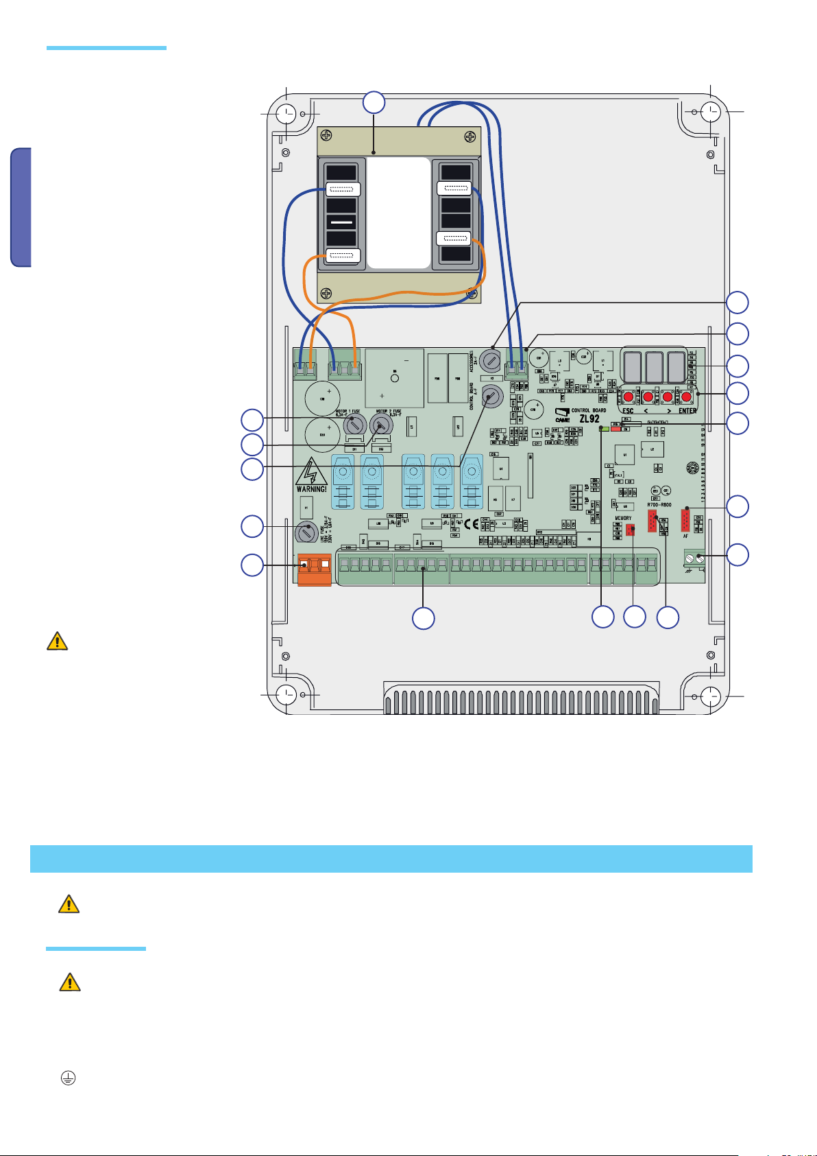
Main component parts
1 -Transformer
2 -Card fuse
3 -Accessories fuse
4 -Display
5 -Memory roll card connector
6 -AF card connector
7 -R700 or R800 card connector
8 -Lack of calibration warning LED
ENGLISH
indicator
9 -Programming buttons
10 -Terminal boards
11 -230 V power terminal boards
12 -Line fuse
13 -Current on-line warning LED indicator
14 -Motor 1 fuse
15 -Motor 2 fuse
16 -Antenna connection terminal board
17 -Thermal terminal board
14
15
2
1
26V
17V
0V
230V
0
3
17
4
9
8
12
11
10
Warning! Before doing any work on
13
the control panel, make sure to cut
off the main current or disconnect
the batteries.
Installation
Installation must be done by qualified, expert staff and in full compliance with current laws and regulations.
6
16
5
7
Preliminary checks
Before installing, do the following:
• Check that the control panel is anchored to a solid surface which is protected from possible impacts, and that the nuts, bolts,
wall plugs, etc., are suitable for the job.
• Make sure you have a suitable omnipolar cut-off device with contacts more than 3 mm apart, and independent (sectioned off)
power supply.
•
Make sure that any connections inside the box (that provide continuance to the protective circuit) are fitted with extra insulation
as compared to the other conductive parts inside.
• Set up proper pipes and conduits for electrical cables to pass through, making sure these are protected from mechanical damage.
P. 4 - Manua l code: 319V21E N Vers. 3 04/2017 © CAME cancelli automat ici S.p.A. - The da ta and information in this manu al are subject to change at any ti me without prior notice requi red by Came Cancelli Automatici S. p.A.
Page 5
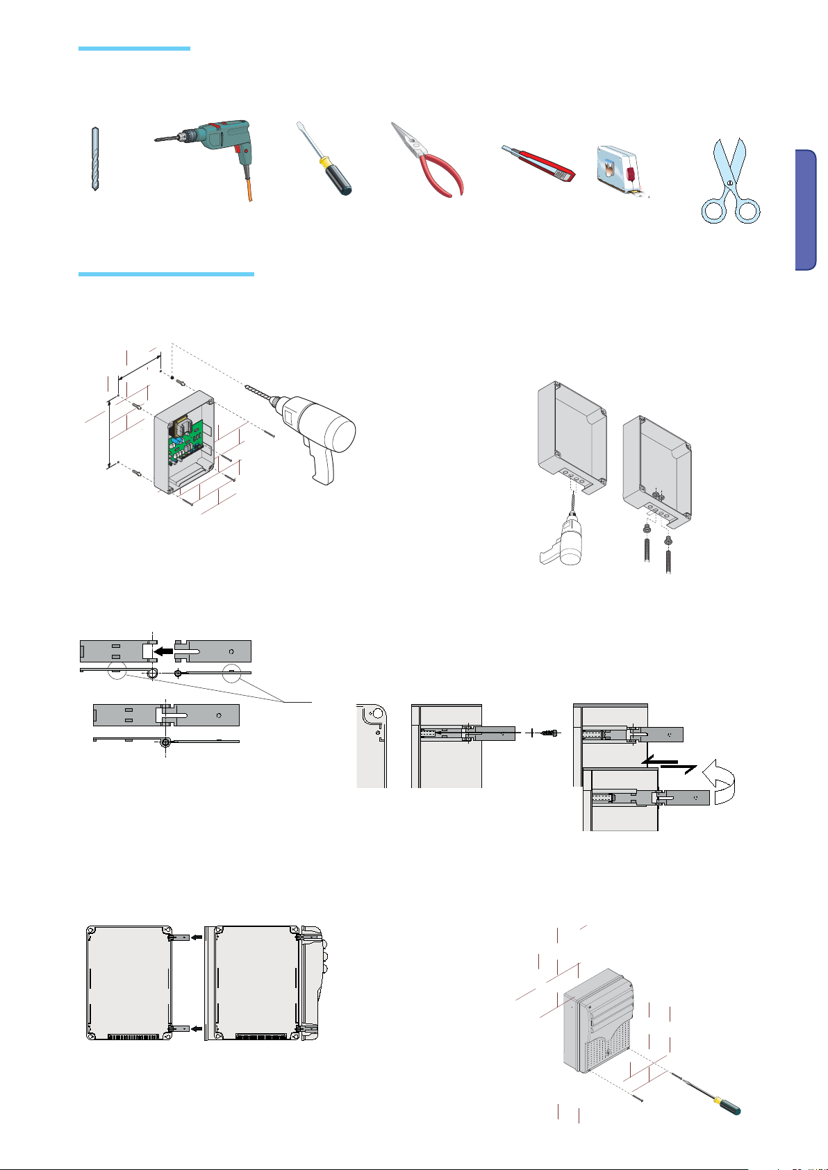
Tools and equipment
Make sure you have all of the tools and materials you will need to proceed with the installation in total safety, according to current
rules and regulations.
Here are some examples.
Anchoring and mounting the box
1) Secure the base of the panel to a protected area; we
suggest using cross slot Phillips head bolts of max. 6
mm in diameter.
2) Perforate the pre-punched holes and insert the cable
glands with the corrugated tubing for the electrical cables to
travel through.
N.B.: diameter of the pre-punched holes: 20 mm.
ENGLISH
3) Assemble the pressure hinges.
4) Insert the hinges into the box (either on the right or left side, as you
prefer) and secure them using the supplied nuts and bolts.
!!
Slide the hinges
so they can rotate.
15 mm~
5) Snap the hinge covers into place.
P. 5 - M anual code: 319V2 1EN Vers. 3 04/2017 © CAME cancelli a utomatici S.p.A . - The data and information in th is manual are subject to chan ge at any time without prior noti ce required by Came Cancelli Automati ci S.p.A.
6) After any calibrations and adjustments, secure the
cover using the supplied screws.
Page 6
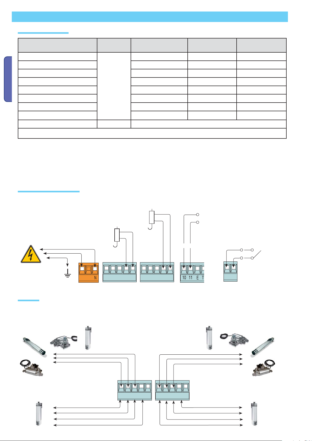
Electrical connections
Cable types and sections
Connections Type of cable
Control panel power supply
Power supply to motor* with encoder 3G x 1,5 mm
Power supply to motor**with encoder 4G x 1,5 mm
Flashing light 2 x 1,5 mm
ENGLISH
Photocell transmitters 2 x 0,5 mm
Photocell receivers 4 x 0,5 mm
FROR CEI
20-22
CEI EN
50267-2-1
Power supply to accessories 2 x 0,5 mm
Command and safety devices 2 x 0,5 mm
Length of cable
1 < 10 m
3G x 1,5 mm
2
2
2
2
2
2
2
2
Length of cable
10 < 20 m
3G x 1,5 mm
3G x 1,5 mm
4G x 1,5 mm
2 x 1,5 mm
2 x 0.5 mm
4 x 0,5 mm
2 x 0,5 mm
2 x 0,5 mm
2
2
2
2
2
Length of cable
20 < 30 m
2
2
2
3G x 2,5 mm
3G x 2,5 mm
4G x 2,5 mm
2 x 1,5 mm
2 x 0,5 mm
4 x 0,5 mm
2 x 1 mm
2 x 0,5 mm
Antenna connection RG58 Maximum 10 m
* MYTO ME - FROG J - AMICO - STYLO RME / ** STYLO ME
N.B.: If the cable length differs from that specified in the table, then you must determine the proper cable diameter based on the
actual power draw from the connected devices and according to the CEI EN 60204-1 standards.
For connections that require several, sequential loads, the sizes given on the table must be re-evaluated based on actual power
draw and distances.
When connecting products that are not specified in this manual, please follow the documentation provided with said products.
Power source and accessories
2
2
2
2
2
2
2
2
12 V – 15 W maximum, Electro-lock for the
Myto, Frog-J, Amico and Stylo RME motors
Possible second 12 V – 1 W max. electrolock
for the Myto, Frog-J, Amico and Stylo RME
motors
Power supply 230
V AC
frequency 50/60 Hz
L
M1 N1 ENC1 EB1 V1
Gearmotor
M1 – 24 V DC gearmotor featuring delayed action on
opening
MYTO ME
STYLO RME STYLO RME
AMICO
M2 N2 ENC2 EB2 V2
M2 - 24V DC gearmotor featuring delayed action on
closing
Terminals for powering the following
accessories:
- 24 V AC, DC Overall power allowed:
50 W
Possible output of the radio receiver’s
second channel (N.O. socket).
Max. socket rating: 500 mA – 24 V DC.
+ -
" "
MYTO ME
AMICO
FROG-J
STYLO ME
M1 N1 ENC1 EB1 V1
FROG-J
M2 N2 ENC2 EB2 V2
STYLO ME
P. 6 - Manua l code: 319V21E N Vers. 3 04/2017 © CAME cancelli automat ici S.p.A. - The da ta and information in this manu al are subject to change at any ti me without prior notice requi red by Came Cancelli Automatici S. p.A.
Page 7
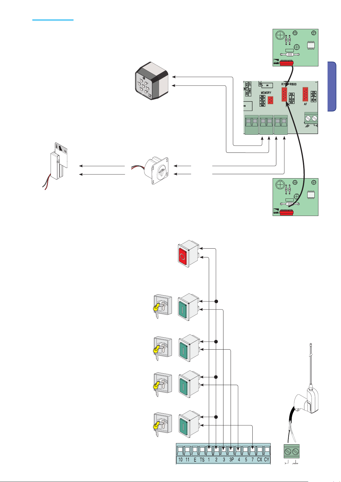
Command devices
001S7000 – Keypad selector
N.B. : insert the (R800)
decoder card to have
the (S7000) keypad
selector recognised.
CANCELLI AUTOMATICI
R800
ENGLISH
001LT001 - Magnetic card reader
ACCESS CONTROL
001TSP00 - Transponder sensor
Stop button (N.C. contact) - Button to stop gate while
excluding the automatic closing cycle. For movement to
resume you must press the command button or transmitter button.
N.B.: if the contact is unused, select “0” = (Disabled)
from the F1 functions menu.
CAME
A B S1 GND
Red
Black
N.B. : insert the (R700) decoder
card to have the (TSP00) sensor or
(LT001) card reader recognised.
CANCELLI AUTOMATICI
R700
Key selector and/or opening button (N.O. contact)
- Gate opening command.
Key selector and/or partial opening button (N.O.
contact) - Partial gate opening for pedestrian
access.
Key selector and/or closing button (N.O. contact)
- Gate closing command.
Key selector and/or commands button (N.O.
contact) - Commands for opening and closing
the gate – pressing the button or turning the
key-switch, inverts the gate’s movement or
stops it depending on how it is set on the 2-7
command in the “FUNCTIONS” menu.
P. 7 - M anual code: 319V2 1EN Vers. 3 04/2017 © CAME cancelli a utomatici S.p.A . - The data and information in th is manual are subject to chan ge at any time without prior noti ce required by Came Cancelli Automati ci S.p.A.
Antenna with RG58
cable for the remote
control.
Page 8
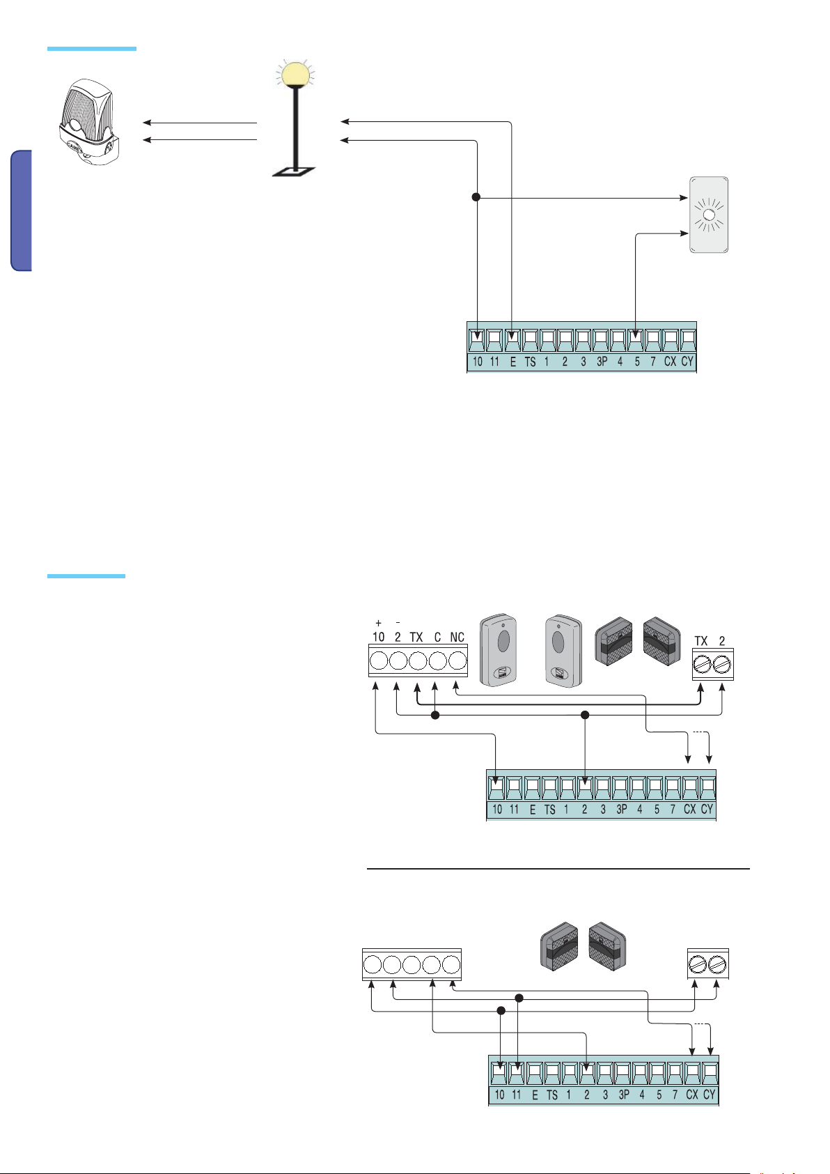
Warning devices
Open gate indicator-light (Socket rating: 24 V – 3 W max.). It
turns on when the gate is open.
It turns off when the gate is
closed (see function “F10”).
Flashing light (socket
rating: 24 V DC - 25 W
max.) – It flashes during
ENGLISH
opening and closing
phases of leaf.
Courtesy or cycle light (contact rated up to:
24V – 25 W max.) – auxiliary connection of
an outdoor lamp that can be freely positioned, for additional lighting of the driveway.
Cycle light: It stays on from the moment the
gate begins opening until it is fully closed
(including the automatic closing time).
Courtesy light: Stays on for a fixed time
period (see function “F25”).
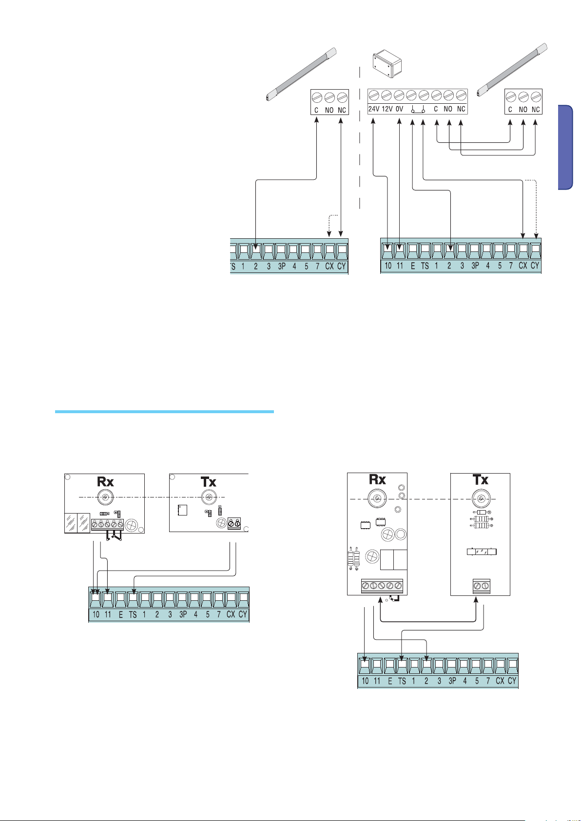
Safety devices
Confi gure either (N.C.) contacts CX or CY , input for EN
12978 compliant safety devices such as photocells.
See CX (F2 Function) or CY(F3 Function) input functions
in:
- C1 «re-open during closing phase», when the gate
leaf is closing, opening the contact triggers the inversion of the direction of movement until the gate leaf is
fully open.
- C2 «re-close during opening phase», when the gate
leaf is opening, if the contact is opened it triggers an
inversion of the direction until gate leaf is fully closed;
- C3 «partial stop», halts moving gate leaves and
causes them to automatically close (if this functions has
been selected);
- C4 «stand-by obstacle», stops the moving gate leaves
causing them to start moving again once obstacle is
removed.
N.B. : if CX and CY contacts are unused they need
to be deactivated during programming.
RX TX
RX TX
DIR
photocells
DELTA
photocells
DELTA-S
photocells
./ # .#
P. 8 - Manua l code: 319V21E N Vers. 3 04/2017 © CAME cancelli automat ici S.p.A. - The da ta and information in this manu al are subject to change at any ti me without prior notice requi red by Came Cancelli Automatici S. p.A.
Page 9
Confi gure either (N.C.) contacts CX or CY,
input for safety devices such as sensate
edges, that comply with
EN 12978 standards. See CX (F2 Function)
or CY(F3 Function) input functions in:
- C7 «re-open while closing», during gate
closing, opening the contact causes inversion of movement until gate is fully open;
- C8 «re-close while opening», during gate
opening, opening the contact causes inversion of movement until gate is fully close.
N.B. : if CX and CY contacts are unused
they need to be deactivated during
programming.
DF
DF with monitoring card
for DFI connections.
ENGLISH
Electrical connection for running the photocells safety test
DOC / DELTA
./
#
.#
DIR / DELTA S
#
48
.#
&53)"),%M!
48
48
At each opening and closing command, the control board assesses the e ciency status of the safety devices (photocells). Any
anomaly found is signaled with the fl ashing of the LED on the control board. Consequently it cancels any commands coming from
the transmitter or the button.
Electrical connection to enable the photocell safety test:
- the transmitter and the receiver, must be connected as per the diagram;
- from the “F5” function select which inputs to run the safety test on.
P. 9 - M anual code: 319V2 1EN Vers. 3 04/2017 © CAME cancelli a utomatici S.p.A . - The data and information in th is manual are subject to chan ge at any time without prior noti ce required by Came Cancelli Automati ci S.p.A.
Page 10

Programming
Description of commands
ENGLISH
Navigazione menu
ENTER
The ESC key is for:
- exiting the menu;
- cancelling modifications.
- shifting from one menu item to another;
- increase or decrease values.
To enter the menu, keep the
ENTER key pressed for at least
one second.
{
The < > keys are for:
F I
ESC < > ENTER
{
F
i
{
Display
The ENTER key is for:
- entering the menu;
- confirming and memorising set value.
< >
< >
< >
To increase or reduce
values, use the greater than-lesser than
keys...
Even for the “submenus”, use the
greater than-lesser
than arrows…
To increase or reduce
values, use the greater
than-lesser than keys...
F
...then press ENTER
i
F
2
ENTER
3
...then press ENTER
F
0
i
…then press ENTER to confirm…
03
ENTER
ENTER
i3
...to exit the menu, wait 10 seconds,
or press ESC,.
ESC
N.B.: when the menu is active, the system cannot be used.
P. 10 - Ma nual code: 319V21E N Vers. 3 04/2017 © CAME cancelli auto matici S.p.A. - T he data and information in this m anual are subject to chang e at any time without prior notice re quired by Came Cancelli Automatic i S.p.A.
Page 11

Menu structure
F 1 – “Total stop” Function
F 2 – function assigned to CX input
F 3 – function assigned to CY input
F 5 – Safety test function
F 6 – maintained action function
F 7 – Command mode on 2-7
F 8 – Command mode on 2-3p
F 9 – Obstacle detection function when motor is stopped
F 10 – Warning light function
F 11 – Exclude Encoder function
F 12 – Slow start function
F 13 – Closing thrust function
F 14 – Sensor type selector function
F 16 – Ram head blow function (only for Myto – Amico – Frog J - Stylo RME motors)
F 17 – Lock function (only for Myto – Amico – Frog J - Stylo RME motors)
F 18 – Supplementary light function
F 19 – Automatic closing time
F 20 – Automatic closing time after partial opening
F 21 – pre-flashing time
F 22 – Working time
F 23 – Delay opening time
F 24 – Delay closing time
F 25 – Courtesy light time
F 26 – Ram head blow time (only for Myto – Amico – Frog J - Stylo RME motors)
F 27 – lock time (only for Myto – Amico – Frog J - Stylo RME motors)
F 28 – M1 motor speed adjustment
F 29 – M2 motor speed adjustment
F 30 – M1 motor speed slow-down time adjustment
F 31 – M2 motor speed slow-down time adjustment
F 32 – Additional closing slow down adjustment for M1 and M2 motors (only for Myto and Stylo with straight-arms)
F 33 – Calibration speed adjustment
F 34 – Sensitivity during movement
F 35 – Sensitivity during slow-downs
F 36 – Adjusting partial openings
F 37 – Adjusting the initial slow-down point of the M1 motor when opening
F 38 – Adjusting the initial slow-down point of the M1 motor when closing
F 39 – Adjusting the point the M1 motor begins drawing to the fully open position
F 40 – Adjusting the point the M1 motor begins drawing to the fully closed position
F 41 – Adjusting the initial slow-down point of the M2 motor when opening
F 42 – Adjusting the initial slow-down point of the M2 motor when closing
F 43 – Adjusting the initial drawing to stop point of the M2 motor when opening
F 44 – Adjusting the initial drawing to stop point of the M2 motor when closing
F 45 – Adjusting an additional slow-down point when closing (only for Myto and Stylo RME with straight-arms)
F 46 – Adjusting the number of motors
F 50 – Saving data in memory roll
F 51 – Reading memory roll data
U 1 – Type of command to associate to a user via radio command
U 2 – Cancelling single users
U 3 – Cancelling all user
A 1 – Setting the type of gearmotor
A 2 – Motor tests
A 3 – Gate run calibration
A 4 – Resetting parameters
H 1 – Software version
ENGLISH
P. 11 - Manua l code: 319V21E N Vers. 3 04/2017 © CAME cancelli automati ci S.p.A. - The da ta and information in this manua l are subject to change at any ti me without prior notice requi red by Came Cancelli Automatici S. p.A.
Page 12

IMPORTANT! Before setting adjusting any functions, set which gearmotors are installed in the system (A 1 – Motor type),
check the gate’s proper direction of travel of (A 2 – Motors test) and calibrate the gate run (A 3 – Gate run calibration)
Note: press ENTER to confirm after choosing each function value.
Motors test and calibration menu
ENGLISH
A 1 (Motor type) : setting up the type of swing gate gearmotor installed.
1 = Stylo ME with jointed-arm; 2 = Stylo ME with straight arm; 3 = Myto; 4 = Frog-J; 5 =
Amico; 6 = Stylo RME with jointed-arm; 7 = Stylo RME with straight arm
ENTER > > ENTER
>...> >
i
F
A I
7 6
i
2
5
> > > >
3
4
A 2 (motors test) : activating the test to verify the proper turning direction of the gearmotors (see “motors test” paragraph).
0 = Deactivated; 1 = Activated.
ENTER
i
F
>...>
A2
ENTER
0
>
i
>
A 3 (Calibrating the gate run) : automatic calibration of the gate run on both gearmotors (see “gate run calibration” paragraph).
0 = Deactivated; 1 = Activated
ENTER
i
F
>...>
A3
ENTER
0
>
i
>
A 4 (Reset parameters): data resetting (default setting) and cancelling the gate run calibration.
0 = Deactivated; 1 = Activated.
ENTER
i
F
>...>
A4
ENTER
0
>
>
i
P. 12 - Manual code: 319V 21EN Vers. 3 0 4/2017 © CAME cancelli auto matici S.p.A. - T he data and information in this m anual are subject to chang e at any time without prior notice re quired by Came Cancelli Automatic i S.p.A.
Page 13

Functions menu
F 1 (Total Stop) : this function stops the gate and consequently excludes any automatic closing cycle; for movement to resume,
you need to use the keypad or transmitter. Insert the safety device on [1 -2]; if unused, select “0” function.
0 = Deactivated; 1 = Activated (default setting)
i
ENTER
F 2 (CX input): the N.C. safety contact input can take on the following functions: C1 (re-opening when closing), C2 (re-closing
when opening), C3 (partial stop), C4 (obstacle stall), C7 (re-opening when closing, for sensitive edges), C8 (re-closing when
opening, for sensitive edges) or, be deactivated. See safety devices on electrical connections.
0 = Deactivated (default setting); 1 = C1; 2 = C2; 3 = C3; 4 = C4; 7 = C7; 8 = C8.
ENTER >
F
F
ENTER >
i
0
2
F
ENTER
i
>
0
>
i
>
2
>
3
>
>
8
>
F 3 (CY Input): safety contact input can take on the following functions: C1 (re-opening when closing), C2 (re-closing when
opening), C3 (partial stop), C4 (obstacle stall), C7 (re-opening when closing, for sensitive edges), C8 (re-closing when opening, for
sensitive edges) or, be deactivated.
See safety devices on electrical connections.
0 = Deactivated (default setting); 1 = C1; 2 = C2; 3 = C3; 4 = C4; 7 = C7; 8 = C8.
7
>
4
ENGLISH
i
ENTER > > >
F
>...>
3
F
ENTER
0
i
2
3
>
>
8
F 5 (Safety Test) : allows the card to check the efficiency of any safety devices (i.e. photocells) after every opening or closing
command.
0 = Deactivated (default setting); 1 = CX; 2 = CY; 3 = CX+CY
i
F
ENTER
F 6 (Maintained action) : the gate works by keeping the button pressed (button 2-3 for opening, button 2-4 for closing, or if set
to the “Closing” function, only with button 2-4. (This excludes all other command devices including radio commands).
0 = Deactivated (default setting); 1 = Activated.
>...>
5
F
ENTER
0
>
>
i
>
7
>
2
>
4
3
>
i
F
ENTER > > ENTER
P. 13 - Manual code: 319 V21EN Ver s. 3 04/2017 © CAME cancell i automatici S.p.A . - The data and informatio n in this manual are subject to ch ange at any time without prior n otice required by Came Cancelli Autom atici S.p.A.
>...>
F
6
0
i
Page 14

F 7 (2-7Command) : setting the contact on 2-7 to step-by-step (open-close) or sequential (open-stop-close-stop).
0 = step-by-step (default setting); 1 = sequential.
i
F
ENTER > > ENTER
F 8 (2-3P Command) : setting the 2-3P contact to pedestrian opening (second gate leaf opens fully) or partial (second gate leaf
ENGLISH
opens partially depending on the time setting of the percentage between 10 and 80 of the gate run, function “F36”).
0 = pedestrian opening (default setting); 1 = partial setting.
F
ENTER >
F 9 (Obstacle detection) : when motor is stopped (gate closed or after a total stop command) it prevents any movement if safety
devices, such as photocells, detect any obstacles.
0 = Deactivated (default setting); 1 = Activated.
>...>
i
>...>
7
F
8
F
ENTER
0
0
i
>
i
i
F
ENTER > > ENTER
F 10 (Opening Warning light) : light bulb connected on 10-5, warns of gate status.
0 = gate open and moving, stays on (default setting)
1 = - gate opening, flashes on and off every half second;
ENTER > > ENTER
ENTER
F
F 11 (Exclude Encoder): excludes encoder from managing slow-downs, obstacle detection and sensitivity.
0 = Encoder activated (default setting); 1 = Encoder deactivated.
F
>...>
i
i
>...>
>...>
F
F0 i
F i i
9
0
- gate closing, flashes on and off every second;
- gate open, stays on;
- gate closed, stays off.
0
0
> > ENTER
i
i
i
F 12 (Slowed-down thrust): at each opening or closing command, the gate leaves move slower for a few seconds.
0 = Deactivated (default setting), 1 = Activated.
ENTER > > ENTER
>...>
i
F
F2 i
0
i
P. 14 - M anual code: 319V2 1EN Vers. 3 04/2017 © CAME cancelli a utomatici S.p.A . - The data and information in th is manual are subject to chan ge at any time without prior noti ce required by Came Cancelli Automati ci S.p.A.
Page 15

F 13 (closing thrust) : at the closing endpoint, the gearmotors give the gate leaves a brief final-closing thrust.
0 = Deactivate (default setting); 1 = 1. = Minimum thrust 2. = Medium thrust 3. = Maximum thrust
i
F
ENTER > > ENTER>...>
F 14 (Type of sensor) : setting the type of sensor for the operator command via (TSP00) transponder or (LT001) magnetic card
reader with R700 encoder card or S7000 keyboard with R800 encoder card.
0 = TAG; 1 = S7000 (default setting).
i
F
ENTER > > ENTER
F 16 (Ram head blow): before any opening run, the gate leaves will press onto the mechanical endstop for a few seconds, to help
release the electro-lock (to set the time, see “F26”).
Note: this function is only visible for the Myto, Frog.J, Stylo-RME and Amico gearmotors.
0 = Deactivate (default setting); 1 = Activate.
i
F
ENTER > > ENTER
>...>
>...>
F3 i
F4 i
F6 i
0
0
0
i
i
i
2
>
3
>
ENGLISH
F 17 (Lock): releasing the electrolock while closing and opening (for time setting see “F27” function).
Note: Myto, Frog.J, Stylo-RME and Amico gearmotors.
0 = with opening command (default setting); 1 = with closing command; 2 = with both commands.
ENTER > > ENTER
F 18 (10-E Light) : output on contact 10-E for light with following function:
- movement flashing, flashes during gate opening and closing.
- outdoor lamp that can be freely positioned, for additional lighting of the driveway – is set up as a courtesy light and stays on for
an adjustable time interval (see function “F25”) or as a cycle light, which stays on from the moment the gate leaf begins to open,
until it is fully closed (including automatic closing time).
0 = Flashing light (default setting); 1 = Cycle; 2 = Courtesy.
i
ENTER > > ENTER
F 19 (Automatic Closing time) : The automatic closing timer activates at each opening endpoint. The predetermined time may be
adjusted, and is in any case dependent on any safety devices that may activate; and it does not activate after a total safety “stop”
or during a power outage.
The waiting time can be deactivated or set to between 1” and 180”.
0 = Deactivated (default setting); 1 = 1 second; 2 = 2 seconds; .................. 180 = 180 seconds.
F
>...>
>...>
i
F
F7 i
F8 i
0
0
i
i
2
>
2
>
i
F
ENTER
P. 15 - Manual code: 319 V21EN Vers . 3 04/2017 © CAME cancell i automatici S.p.A . - The data and information i n this manual are subject to cha nge at any time without prior n otice required by Came Cancelli Autom atici S.p.A.
>...>
F9 i
ENTER
0
>
i
>
> >
I08
Page 16

F20 (Automatic closing time after partial or pedestrian opening) : Automatic closing time of the gate leaf after a partial opening or pedestrian command. Once this time has elapsed, the gate automatically closes and it is in any case conditioned by any
safety devices that may be triggered, and is deactivated after a total safety “stop” or due to a power failure.
The waiting time can be deactivated or set to between 1” and 180”.
Note: the automatic closing time (see F 19) must not be deactivated.
1 = 1 second; 2 = 2 seconds; .................. 5 = 5 seconds (default setting); .................. 180 = 180 seconds.
ENTER
ENGLISH
i
F
>...>
F02 I08
ENTER
i
> >
2
> >
F 21 (Pre-flashing time) : after an opening or closing command, the flashing light, connected to 10-E, starts flashing for a preset
time interval before starting the gate run.
The pre-flashing time can be deactivated or set to between 1” and 10”.
0 = deactivated (default setting); 1 = 1 second; 2 = 2 seconds; .................. 10 = 10 seconds.
ENTER
i
F
>...>
F i2
ENTER
0
> >
i
> >
0 I
F 22 (Working time) : working time of the motors when opening or closing.
The working time may be set to between 5” and 120”.
5 = 5 seconds; .................. 12 0 = 120 seconds; (default setting).
ENTER
i
F
>...>
F22
ENTER
5
> >
6
> >
I02
F 23 (Opening slow-down time) : after and opening command, the gate leaf of the M1 gearmotor delays opening compared to
the M2 gearmotor for an adjustable time interval,
The delay time can be deactivated or set to between 1” and 10”.
0 = deactivated (default setting); 1 = 1 second; 2 = 2 seconds; .................. 10 = 10 seconds.
ENTER
i
F
>...>
F32
ENTER
0
> >
i
> >
0 I
F 24 (Closing slow-down time) : after and closing command, the gate leaf of the M2 gearmotor delays opening compared to the
M1 gearmotor for an adjustable time interval,
The delay time can be deactivated or set to between 1” and 25”.
0 = deactivated (default setting); 1 = 1 second; 2 = 2 seconds; .................. 25 = 25 seconds.
ENTER
i
F
>...>
F42
ENTER
0
> >
i
> >
52
P. 16 - Ma nual code: 319V21E N Vers. 3 04/2017 © CAME cancelli au tomatici S.p.A. - T he data and information in this m anual are subject to chang e at any time without prior noti ce required by Came Cancelli Automati ci S.p.A.
Page 17

F 25 ( Courtesy light time) : supplementary light connected on (10-E), stays on while gate is opening and closing.
The time can be set to between 60” and 180”.
60 = 60 seconds (default setting); 61 = 61 seconds ..................; 180 = 180 seconds.
ENTER
i
F
>...>
F52
ENTER
06
> >
i6
I08
> >
F 26 (Ram head blow) : thrust time of the gearmotor when in final closing and opening stage after each command.
The time may be set to between 1” and 2”.
Note: this function only appears for the Myto, Frog-J, Stylo-RME and Amico gearmotors.
1 = 1 second (default setting); 2 = 2 seconds.
ENTER > > ENTER
>...>
i
F
F62
i
2
F 27 (lock time) : action time for releasing the electrolock with each opening or closing command (see F 17).
The time can be set to between 1” and 4”.
Note: this function only appears for the Myto, Frog-J, Stylo-RME and Amico gearmotors.
1 = 1 second (default setting); ................... 4 = 4 seconds.
ENTER
i
F
>...>
F72
ENTER
i
> >
2 4
3
>
ENGLISH
>
F 28 (M1 motor speed) : setting the speed of operation of the M1 motor calculated as a percentage:
40 = 40% of the motor speed(minimum); .................. 100 = 100% of the motor speed (maximum and default setting).
ENTER
i
F
>...>
F82
ENTER
04
> >
i4
I00
> >
F 29 (M2 motor speed) : setting the speed of operation of the M2 motor calculated as a percentage:
40 = 40% of the motor speed(minimum); .................. 100 = 100% of the motor speed (maximum and default setting).
ENTER
i
F
>...>
F92
ENTER
04
> >
i4
I00
> >
F 30 (Slow-down speed of M1 motor) : setting the speed of the M1 motor during slow downs, calculated as a percentage.
20 = 20% motor slow-down speed (minimum); .................. 50 = 50% motor slow-down speed (default setting);
................. 60 = 60% motor slow-down speed (maximum).
i
ENTER
P. 17 - Manual code: 319 V21EN Vers. 3 04/2017 © CAME ca ncelli automatici S.p. A. - The data and informat ion in this manual are subjec t to change at any time without pr ior notice required by Came Cancell i Automatici S.p.A .
F
>...>
F03
ENTER
02
> >
i2
>
06
>
Page 18

F 31 (Slow-down speed of M2 motor) : setting the speed of the M2 motor during slow downs, calculated as a percentage.
20 = 20% motor slow-down speed (minimum); .................. 50 = 50% motor slow-down speed (default setting); .................
60 = 60% motor slow-down speed (maximum).
i
ENTER
F 32 (Additional slow-down when closing of M1 + M2) : Setting of an additional reduction in speed during closing slow-downs
ENGLISH
F
>...>
F i3
ENTER
02
> >
i2
>
06
for the straight-arm M1 and M2 motors; the reduced speed is calculated as a percentage.
Note: this function only appears for the Myto, and Stylo straight-arm gearmotors.
10 = 10% motor slow-down speed (minimum); .................. 50 = 50% motor slow-down speed (maximum and default setting)
ENTER
i
F
>...>
F23
ENTER
0 I
> >
I I
>
05
F 33 (calibration speed) : setting the speed only for the gate calibration phase, calculated as a percentage.
30 = 30% of the motor speed; ........ 50 = 50% of the motor speed (default setting); ...... 60 = 60% of the motor speed.
ENTER
i
F
>...>
F33
ENTER
03
> >
i3
>
>
>
06
>
F 34 (gate run sensitivity) : adjusts the obstacle detection sensitivity during the gate runs.
10 = maximum sensitivity; .................. 100 = minimum sensitivity (default sensitivity).
ENTER
i
F
>...>
F43
ENTER
0 I
> >
I I
>
I00
>
F 35 (Slow-down sensitivity) : adjusts the obstacle detection sensitivity during slow-downs.
10 = maximum sensitivity; .................. 100 = minimum sensitivity (default sensitivity).
ENTER
i
F
>...>
F53
ENTER
0 I
> >
I I
>
I00
>
F 36 (Adjusting Partial Opening) : adjusts the opening of the gate leaf of the M2 (second) motor as a percentage of the total gate
run.
10 = 10% of the gate run (default setting); .................. 80 = 80% of the gate run.
ENTER
i
F
>...>
F63
ENTER
0 I
> >
I I
>
08
>
P. 18 - Ma nual code: 319V21E N Vers. 3 04/2017 © CAME cancelli au tomatici S.p.A. - T he data and information in this m anual are subject to chang e at any time without prior noti ce required by Came Cancelli Automati ci S.p.A.
Page 19

F 37 (Slow-down point when opening the M1 motor) : adjusts the point at which the M1 motor begins to slow down when opening. The beginning slow-down point is calculated as a percentage of the full gate run (see paragraph illustrating the slow-down
areas and points)
10 = 10% of the gate run; .................. 25 = 25% of the gate run (default setting); .................. 60 = 60% of the gate run.
ENTER
i
F
>...>
F73
ENTER
0 I
> >
I I
>
06
>
F 38 (Slow-down point when closing the M1 motor) : adjusts the point at which the M1 motor begins to slow down when
closing. The beginning slow-down point is calculated as a percentage of the full gate run (see paragraph illustrating the slow-down
areas and points)
10 = 10% of the gate run; .................. 25 = 25% of the gate run (default setting); .................. 60 = 60% of the gate run.
ENTER
i
F
>...>
F83
ENTER
0 I
> >
I I
>
06
>
F 39 (Point when M1 motor draws fully open) : adjusts the point at which the M1 motor begins drawing to the fully-open position
This point is calculated as a percentage of the full gate run (see paragraph illustrating the slow-down areas and points)
1 = 1% of the gate run; .................. 5 = 5% of the gate run (default setting); ..................10 = 10% of the gate run.
ENTER
i
F
>...>
F93
ENTER
i
> >
2
>
0 I
>
ENGLISH
F 40 (Point when M1 motor draws fully closed) : adjusts the point at which the M1 motor begins drawing to the fully-closed
position.
This point is calculated as a percentage of the full gate run (see paragraph illustrating the slow-down areas and points at which
gate draws fully open or closed.)
1 = 1% of the gate run; .................. 5 = 5% of the gate run (default setting); .................. 10 = 10% of the gate run.
ENTER
i
F
>...>
F04
ENTER
i
> >
2
>
0 I
>
F 41 (Point when M2 motor is fully open) : adjusts the point at which the M2 motor begins to be fully-open.
The beginning slow-down point is calculated as a percentage of the full gate run (see paragraph illustrating the slow-down areas
and points at which gate draws fully open or closed)
10 = 10% of the gate run; .................. 25 = 25% of the gate run (default setting); .................. 60 = 60% of the gate run.
ENTER
i
F
>...>
F i4
ENTER
0 I
> >
I I
>
06
>
F 42 (Slow-down point when closing the M2 motor) : adjusts the point at which the M2 motor begins to slow down when
closing. The beginning slow-down point is calculated as a percentage of the full gate run (see paragraph illustrating the slow-down
areas and points at which gate draws fully open or closed)
10 = 10% of the gate run; .................. 25 = 25% of the gate run (default setting); .................. 60 = 60% of the gate run.
i
ENTER
P. 19 - Manual code: 319 V21EN Vers . 3 04/2017 © C AME cancelli automatici S .p.A. - The data and i nformation in this manual ar e subject to change at any time wi thout prior notice required by Ca me Cancelli Automatici S.p. A.
F
>...>
F24
ENTER
0 I
> >
I I
>
06
>
Page 20

F 43 (Point when M2 motor draws fully open) : adjusts the point at which the M2 motor begins drawing to the fully-open position.
This point is calculated as a percentage of the full gate run (see paragraph illustrating the slow-down areas and points at which
gate draws fully open or closed)
1 = 1% of the gate run; .................. 5 = 5% of the gate run (default setting); .................. 10 = 10% of the gate run.
ENTER
ENGLISH
i
F
>...>
F34
ENTER
i
> >
2
>
F 44 (Point when M2 motor draws fully closed) : adjusts the point at which the M2 motor begins drawing to the fully-closed
position.
This point is calculated as a percentage of the full gate run (see paragraph illustrating the slow-down areas and points)
1 = 1% of the gate run; .................. 5 = 5% of the gate run (default setting); .................. 10 = 10% of the gate run.
ENTER
i
F
>...>
F44
ENTER
i
> >
2
>
0 I
F45 (Additional closing slow-down point) : adjusts the point at which there is an additional slow-down when closing, calculated
as a percentage of the slow-down.
Note: this function is visible only for the straight-arm Myto and Stylo gearmotors.
10 = 10% of the slow-down run; ............ 50 = 50% of the slow-down run (default setting); ............ 100 = 100% of the slow-
down run.
0 I
>
>
ENTER
i
F
>...>
F54
ENTER
0 I
> >
I I
F 46 (Number of Motors) : sets the number of motors connected to the control panel.
0 = Engages both the M1 and M2 motors (default setting); 1 = Engages only one, the M2 motor.
i
ENTER > > ENTER
F
>...>
F64
0
i
F 50 (Save data) : saves all users and settings in the memory roll.
Note: this function appears only if the memory roll is inserted into the mother board.
0 = Deactivated; 1 = Activated
i
ENTER > > ENTER
F
>...>
F05
0
i
>
I00
>
F 51 (Data Read out) : loads the data from the memory roll into the mother board.
Note: this function appears only if the memory roll is inserted into the mother board.
0 = Deactivated; 1 = Activated.
i
ENTER > > ENTER
F
>...>
F i5
0
i
P. 20 - Manua l code: 319V21E N Vers. 3 04/2017 © CAME cancelli automat ici S.p.A. - The da ta and information in this manu al are subject to change at any ti me without prior notice requi red by Came Cancelli Automatici S. p.A.
Page 21

User Menu
U 1 (add user with assigned command) : add user (max. 25 users) assigned to a command via transmitter or other device (see
paragraph on adding users with assigned command).
1 = step-by-step command (open-close); 2 = sequential command (open-stop-close-stop); 3 = open only command; 4 = pede-
strian / partial opening command (see function “F8”; 5 = B1-B2 contact output.
i
ENTER > > ENTER
U 2 (Cancel user) : cancels single user (see paragraph on cancelling single users)
ENTER
U 3 (Cancel users) : cancels all memorized users. Press ENTER to confirm.
0 = Deactivated; 1 = Cancel all users.
ENTER > > ENTER
F
i
F
i
F
>...>
>...>
>...>
u i
u2
u3
ENTER
i
> >
i
> >
0
>
3
>
ENGLISH
4
52
>
2
5
2
i
i
ENTER
Info Menu
H 1 (Version) : displays software version.
F
>...>
H I
ENTER
0i.
P. 21 - Manual code: 319V 21EN Vers. 3 0 4/2017 © CAME cancelli auto matici S.p.A. - T he data and information in this ma nual are subject to change a t any time without prior notice re quired by Came Cancelli Automatici S .p.A.
Page 22

CAME
Decoding cards
To insert, change, remove users or to command the operator via radio command, insert the AF43S card.
If using the transponder or card reader, insert the R700 card or, alternatively, the R800 card for the keyboard selector.
Insert the memory roll to save and load all settings including users registered by another card.
R700
ENGLISH
R700
CANCELLI AUTOMATICI
ACCESS CONTROL
LT0 01
TSP00
Memory roll
S7000
R800
CANCELLI AUTOMATICI
R800
Frequency/MHz Card Transmitter
FM 26.995 AF130 TFM
FM 30.900 AF150 TFM
AM 26.995 AF26 TOP
AM 30.900 AF30 TOP
AM 433.92 AF43S TAM / TOP
ATOMO / TWIN
AM 433.92 AF43TW TWIN
TOP
AF
CAME
ATOMO
TAM
TFM
TWIN
AM 40.685 AF40 TOUCH
TOUCH
AM 868.35 AF868 TOP
P. 22 - Manual code: 319V21E N Vers. 3 04/2017 © CAME cancelli automati ci S.p.A. - The data a nd information in this manua l are subject to change at any tim e without prior notice requir ed by Came Cancelli Automatici S. p.A.
Page 23

SC <
SC
<
<
> EN
>
>
<
<
> ENTE
EN TE
>
>
Adding users with an assigned command
N.B.: Before proceeding, remove the memory roll card.
1) Select “U 1”.
Press ENTER to confirm.
ESC < > ENTER
2) select command (1=step-by-step,
2=sequential, 3=open, 4=pedestrian /
partial opening, 5= B1-B2 output contact)
to assign to user via the greater-than and
lesser-than arrows on the keyboard...
3) …an available number between 1
and 25 will flash for a few seconds. This
number will be assigned to the user after
sending the code via transmitter or other
command device.
ESC < > ENTER
U
I
2
8
ESC < > ENTER
Assigned Command user
1 2 3 4 5 6 7 8 9 10 11 12 13 14 15 16 17 18 19 20 21 22 23 24 25 -
ENGLISH
Cancelling single users
1) Select “U 2”.
Press ENTER to confirm.
2) Select the number of the user to cancel
using the greater-than/lesser-than arrow
keys.
Press ENTER to confirm…
3) …”CLr” will be displayed to confirm the
cancellation.
2
L
2
2
U
ESC < > ENTER
ESC < > ENTER
C
P. 23 - Ma nual code: 319V21E N Vers. 3 04/2017 © CAME cancelli auto matici S.p.A. - T he data and information in this m anual are subject to chang e at any time without prior notice re quired by Came Cancelli Automati ci S.p.A.
ESC < > ENTER
Page 24

>
>
Motor tests
1) Select “A2”.
Press ENTER to confirm.
ENGLISH
2) Select 1 to activate test.
Press ENTER to confirm...
a
ESC < > ENTER
2
I
ESC < > ENTER
3) … “---” will be displayed, standing by
for a command…
4) Keep the “>” key pressed down and
check that the gate leaf of the second
gearmotor (M2) opens fully.
Note: if the gate leaf closes instead of
opening, invert the motor phases (M2 with
N2).
5) Carry out the same procedure with the
“<” key to check the gate leaf of gearmotor
(M1).
Note: if the gate leaf closes fully, invert the
motor phases (M1 with N1).
---
ESC < > ENTER
M2M1
oP2
ESC < > ENTER
M2M1
oP I
ESC < > ENTER
P. 24 - Manu al code: 319V21E N Vers. 3 04/2017 © CAME cancelli autom atici S.p.A. - Th e data and information in this man ual are subject to change at a ny time without prior notice req uired by Came Cancelli Automatici S .p.A.
Page 25

<
<
> EN
EN
>
>
Gate run calibration
N.B: before proceeding with the calibration of the gate run, check that the area of movement is free of any obstacles and check
that there is a mechanical stop or both opening and closing.
Important! While calibrating, all safety devices will be disabled until the end of the calibration excluding the “total stop”
1) Select “A3”.
Press ENTER to confirm.
a3
ESC < > ENTER
2) Select 1 and press ENTER to confirm,
the automatic gate run calibration
procedure...
ESC < > ENTER
i
ENGLISH
3) the gate leaf of the first motor will close
fully until the mechanical stop…
4) …then, the gate leaf of the second
motor will do the same…
5) …then, the gate leaf of the second
motor, shall fully open until the mechanical
stop…
cl i
ESC < > ENTER
cl2
ESC < > ENTER
op2
ESC < > ENTER
0
0
0
0
0
0
6) …then, the gate leaf of the first motor
will do the same.
P. 25 - Ma nual code: 319V21E N Vers. 3 04/2017 © CAME cancelli auto matici S.p.A. - T he data and information in this m anual are subject to chang e at any time without prior notice re quired by Came Cancelli Automati ci S.p.A.
op I
ESC < > ENTER
0
0
Page 26

Illustration of the slow-down areas and points at which gate draws to the fully open or closed position
Note: the slow-down areas and points at which the gate draws to the fully open or closed position are tested according to the
parameters set forth by Technical Norms EN12445 and EN12453 regarding compatibility of impact forces generated by moving
gate leaves.
M1
ENGLISH
O
O
D
IL
D
M2
P
B
A
C
FH
B
D
E
M
P
B
Q
A
C
B
D
G
N
O
A = Area of movement at normal speed
B* = Run zone at slow-down speed
C = Encoder intervention zone with movement inversion
D= Encoder intervention zone with movement stop
E = Opening slow-down beginning point (M1 Open Slow- %)
F = Closing slow-down beginning point (M1 Close Slow- %)
G = Opening slow-down beginning point (M2 Open Slow- %)
H = Closing slow-down beginning point (M2 Close Slow- %)
I** = Point at which gate begins drawing to fully-closed position (M1 Close appr. %)
L** = Point at which gate begins drawing to fully-closed position (M2 Close appr. %)
M**= Point at which gate begins drawing to fully-open position (M1 Acc. AP%)
N**= Point at which gate begins drawing to fully-open position (M2Acc. AP%)
O = Mechanical Stops
P = Area in which additional slow- down speed takes place when closing, only for the straight-arm Stylo and Myto motors)
Q = Point at which additional slow-down when closing begins, only for the straight-arm Stylo and Myto motors)
* Minimum 600 mm from the Final full stop.
** Set the function’s approach % “M1 Close appr.” for the fi rst (M1) motor and “M2 Close appr.” for the second (M2) motor from
the “ENCODER” menu so as to obtain a distance of between 1 and 50 mm max. from the fi nal full stop.
P. 26 - Manua l code: 319V21E N Vers. 3 04/2017 © CAME cancelli automa tici S.p.A. - The d ata and information in this manu al are subject to change at any t ime without prior notice requ ired by Came Cancelli Automatici S .p.A.
Page 27

Error messages and warnings
“Er1”: M1 motor calibration interrupted; check proper connection and working state of M1 motor.
“Er2”: motor calibration interrupted; check proper connection and working state of M1 motor.
“Er3”: broken encoder; call for assistance.
“Er4”: services test error; check proper connection and working status of the safety devices.
“Er5”: insufficient working time;
Check time setting, it could be insufficient to complete the working cycle.
“Er6”: maximum number of detected obstacles.
“Er7”: transformer overheated, at first opening command, gate leaves stay open.
“C0”: contact 1-2 (stop) unused and not deactivated.
”C1/2/3/4/7/8”: contacts CX and/or CY are unused and not deactivated.
Red LED indicator light flashes: command card still not calibrated to the gate run.
Phasing out and disposal
In its premises, CAME cancelli automatici S.p.A. implements an Environmental Management System certified in compliance
with the UNI EN ISO 14001 standard to ensure environmental protection.
Please continue our efforts to protect the environment - which CAME considers one of the cardinal elements in the development of
its operational and market strategies - simply by observing brief recommendations as regards disposal:
DISPOSAL OF PACKAGING
The packaging components (cardboard, plastic, etc.) are all classifiable as solid urban waste products and may be disposed of easily,
keeping in mind recycling possibilities.
Prior to disposal, it is always advisable to check specific regulations in force in the place of installation.
PLEASE DISPOSE OF PROPERLY!
ENGLISH
PRODUCT DISPOSAL
Our products are made up of various types of materials. Most of them (aluminium, plastics, iron, electrical wires, etc.) may be disposed of in normal garbage collection bins and can be recycled by disposing of in specific recyclable material collection bins and
disposal in authorized centres.
Other components (electrical boards, remote control batteries, etc.), however, may contain polluting substances.
They should therefore be removed and given to qualified service companies for proper disposal.
Prior to disposal, it is always advisable to check specific regulations in force in the place of disposal.
PLEASE DISPOSE OF PROPERLY!
CE compliance certifi cation
Declaration
provided by directives 2006/95/CE and 2014/30/UE.
An original copy of the declaration of conformity is available on request.
- Came Cancelli Automatici S.p.A. declares that this product conforms to the essential, pertinent requirements
P. 27 - Manual code : 319V21EN Vers. 3 04/2017 © CAME can celli automatici S.p. A. - The data and informat ion in this manual are subjec t to change at any time without pri or notice required by Came Cancelli A utomatici S.p.A.
Page 28

IT • Per ogni ulteriore informazione su azienda, prodotti e assistenza nella vostra lingua:
CAME Cancelli Automatici S.p .A.
Dos son Di Casi er
Assi stenza Tecnic a/N umero Verde 800 295830
www. came.com
Engl ish
319V21EN
3
EN • For any further information on company, products and assistance in your language:
FR • Pour toute autre information sur la société, les produits et l’assistance dans votre langue :
DE • Weitere Infos über Unternehmen, Produkte und Kundendienst bei:
ES • Por cualquier información sobre la empresa, los productos y asistencia en su idioma:
NL • Voor meer informatie over het bedrijf, de producten en hulp in uw eigen taal:
PT • Para toda e qualquer informação acerca da empresa, de produtos e assistência técnica, em sua língua:
PL •
Wszystkie inne informacje dotyczące fi rmy, produktów oraz usług i pomocy technicznej w Waszym języku znajdują się na stronie:
RU •
Для получения дополнительной информации о компании, продукции и сервисной поддержке на вашем языке:
HU • A vállalatra, termékeire és a műszaki szervizre vonatkozó minden további információért az Ön nyelvén:
HR • Za sve dodatne informacije o poduzeću, proizvodima i tehničkoj podršci:
UK • Для отримання будь-якої іншої інформації про компанію, продукцію та технічну підтримку:
www. came.com
3 04/2017 © CAME cancelli automati ci S.p.A.
319V21EN Vers.
English - Manual cod e:
The data and info rmation in this manual are subj ect to change at any time witho ut prior notice required by Came Ca ncelli Automatici S.p.A .
CAME Cancelli Automatici S.p.A.
Via Martiri Della Libertà, 15
31030
Dosson Di Casier (Tv)
(+39) 0422 4940
(+39) 0422 4941
Assistenza Tecnica/Numero Verde 800 295830
 Loading...