

Page 1
AUTOMAZIONE PER CHIUSURA INDUSTRIALE
CONTROL PANEL FOR EMEGA SERIES
ZE5 V.7
INSTALLATION MANUAL
Page 2
TRUCTIONS
TO
SE SER
TO
RUCTION
“IMPORTANT SAFETY INSTRUCTIONS TO FOLLOW DURING INSTALLATION”
WARNING - IMPROPER INSTALLATION MAY CAUSE SERIOUS DAMAGE. FOLLOW ALL INSTALLATION
ENGLISH
THIS MANUAL IS MEANT FOR PROFESSIONAL INSTALLERS OR QUALIFIED PERSONNEL ONLY.
INSTRUCTIONS
1 Legend
THIS SYMBOL INDICATES SECTIONS TO BE READ WITH PARTICULAR CARE.
THIS SYMBOL INDICATES SECTIONS CONCERNING SAFETY.
THIS SYMBOL INDICATES NOTES TO COMMUNICATE TO USERS
2 Use Applications and Destination
2.1 Destination
The ZE5 electrical panel is designed to control EMEGA (E306-E456) automation units in the movement
of garage-type doors with double or single motor.
2.2 Limits of Use
-Observe distances and cable diameters as indicated in the table in chapter 5.4
3 Standards followed
The following standards were complied with for this product: EN 12978, UNI EN 954-1, CEI EN 60335-1,
and UNI EN 12453.
4 Device Description
4.1 Components
230V electric panel for EMEGA series automation systems; 50÷60 Hz frequency.
Wholly designed and built by CAME Cancelli Automatici S.p.A.
Guaranteed 24 months if not tampered with.
4.2 Technical Information
Electric Panel
Power supply: 230V, 50÷60 Hz.
Maximum power allowed: 400 W
Absorption at rest: 150 mA
Maximum power for 24V accessories: 20 W
Maximum power for 230V accessories: 120 W
Degree of protection: IP54
Insulation type: II
Material: ABS
Working temperature:
#
All the data and information contained herein is considered subject to change at any time and at our discretion.
#
2
Page 3
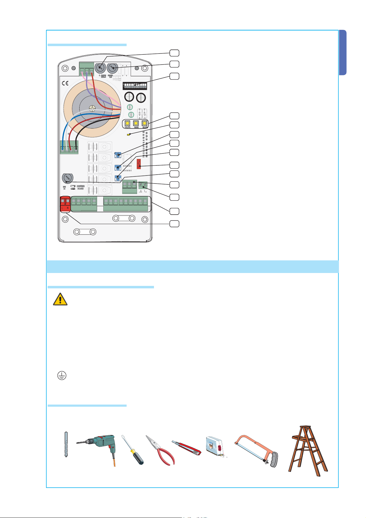
4.3 Main Components
CH1/OP.
AF
V
W
U
E1
E3
FA
ENGLISH
1
24
12
0
ON
1234
5678
910
2
1 630 mA board fuse
3
2 1.6 A fuse for accessories
3 Dip-Switch for function selector
4 Keys for radio code memorisation and for end-
stop programming
4
5
6
L1T
L2T
VA
VB
- A.C.T.+
- AMP. S+
- S. DELAY +
AF
7
8
9
10
5 LED indicator
6 Trimmer for adjusting automatic closing times
7 Encoder sensitivity adjustment trimmer
8 Trimmer for adjusting operation times
9 Radiofrequency board coupling
10 5 A line fuse
11 Encoder connection terminal board
+
-
ZE7
N
L
101011111 2 3 5 7 C1C1FA
E
11
12
13
14
12 Aerial connection terminal board
13 Connection terminal board
14 Power feed terminal board
5 Installation
5 .1 Equipment and materials
Before proceeding with the installation, it is necessary to:
• Make sure the mains power is off.
• Check that the control panel is installed in an area protected from bumps and that the anchorage
surface is solid, and that it is secured with suitable elements (screws, inserts, etc).
• Install suitable tubes and ducts for electric cable passage to guarantee protection against
All the data and information contained herein is considered subject to change at any time and at our discretion.
mechanical damage.
Connections inside the case made for protection circuit continuity are allowed as long as they
•
include additional insulation with respect to other internal drive parts.
5.2 Attrezzi e materiali
Make sure all the necessary tools and materials are available to carry out the installation with the maximum safety, in compliance with regulations in force. Here are some examples:
3
Page 4
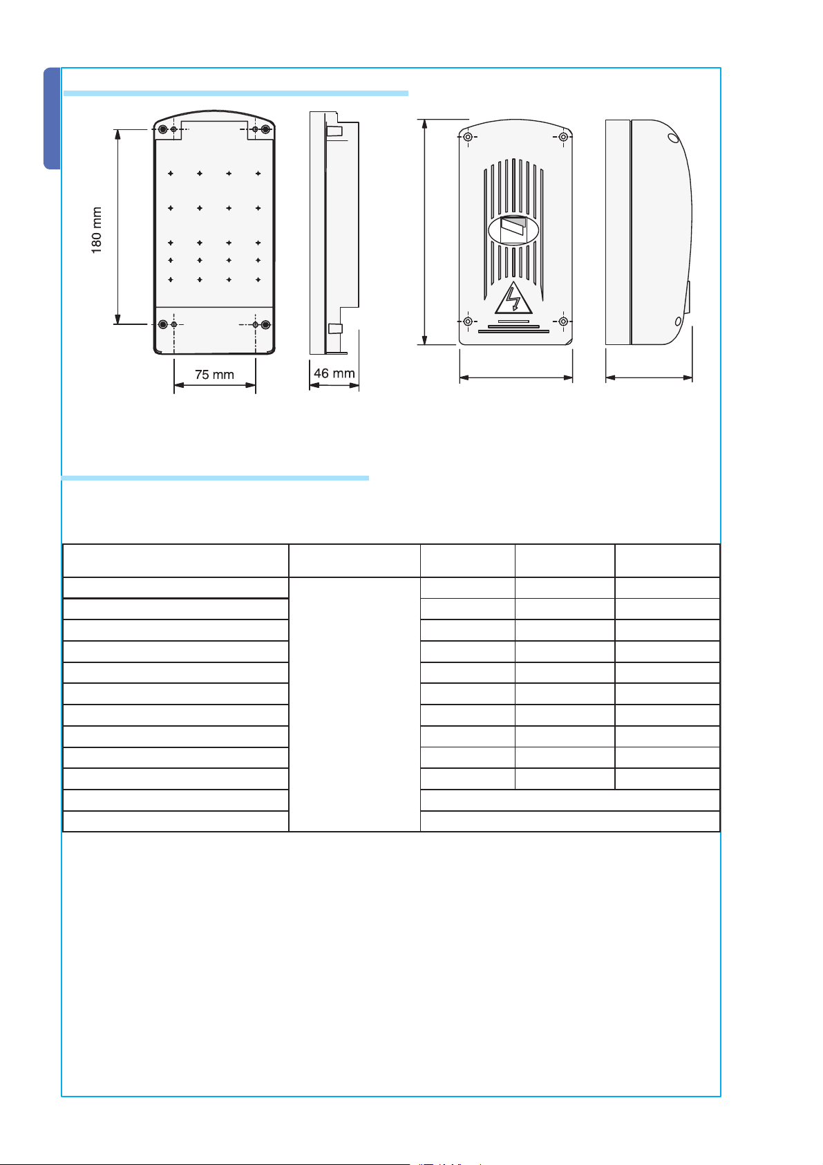
5.3 Dimensions, axle bases and fastening holes
ENGLISH
#!-%
MM
MM
MM
5.4 Minimum thicknesses and cables types
Connections
230V 2F power supply
Cable Type
1<10 m Cable
Length
3G 1,5mm² 3G 2,5mm² 3G 4mm²
230V 2F motors 4G 1mm² 4G 1,5mm² 4G 2,5mm²
230V fl ashing lamp 2 x 0,5mm² 2 x 1mm² 2 x 1,5mm²
230V cycle / courtesy lamps 3G 0,5mm² 3G 1mm² 3G 1,5mm²
Power for 24V accessories 2 x 0,5mm² 2 x 0,5mm² 2 x 1mm²
24V pilot lamp 2 x 0,5mm² 2 x 0,5mm² 2 x 1mm²
24V “in movement” output 2 x 0,5mm² 2 x 0,5mm² 2 x 1mm²
FROR CEI 20-22
CEI EN 50267-2-1
Safety contacts 2 x 0,5mm² 2 x 0,5mm² 2 x 0,5mm²
N.O./N.C. command keys 2 x 0,5mm² 2 x 0,5mm² 2 x 0,5mm²
End-stop 2 x 0,5mm² 2 x 1mm² 2 x 1,5mm²
Aerial connection (max 10m) RG58
Encoder connection (max 30m) Shielded cable 2402C 22AWG
10<20 m
Cable Length
20<30 m Cable
Length
All the data and information contained herein is considered subject to change at any time and at our discretion.
N.B. The evaluation of the section of cables with lengths other than the ones stated in the table should be
considered according to the real absorption of the connected devices, in compliance with the prescriptions in
CEI EN 60204-1 standard.
Table dimensioning should be recalculated according to real absorption and distances for connections requiring more than one charge (sequential) on the same line.
4
Page 5
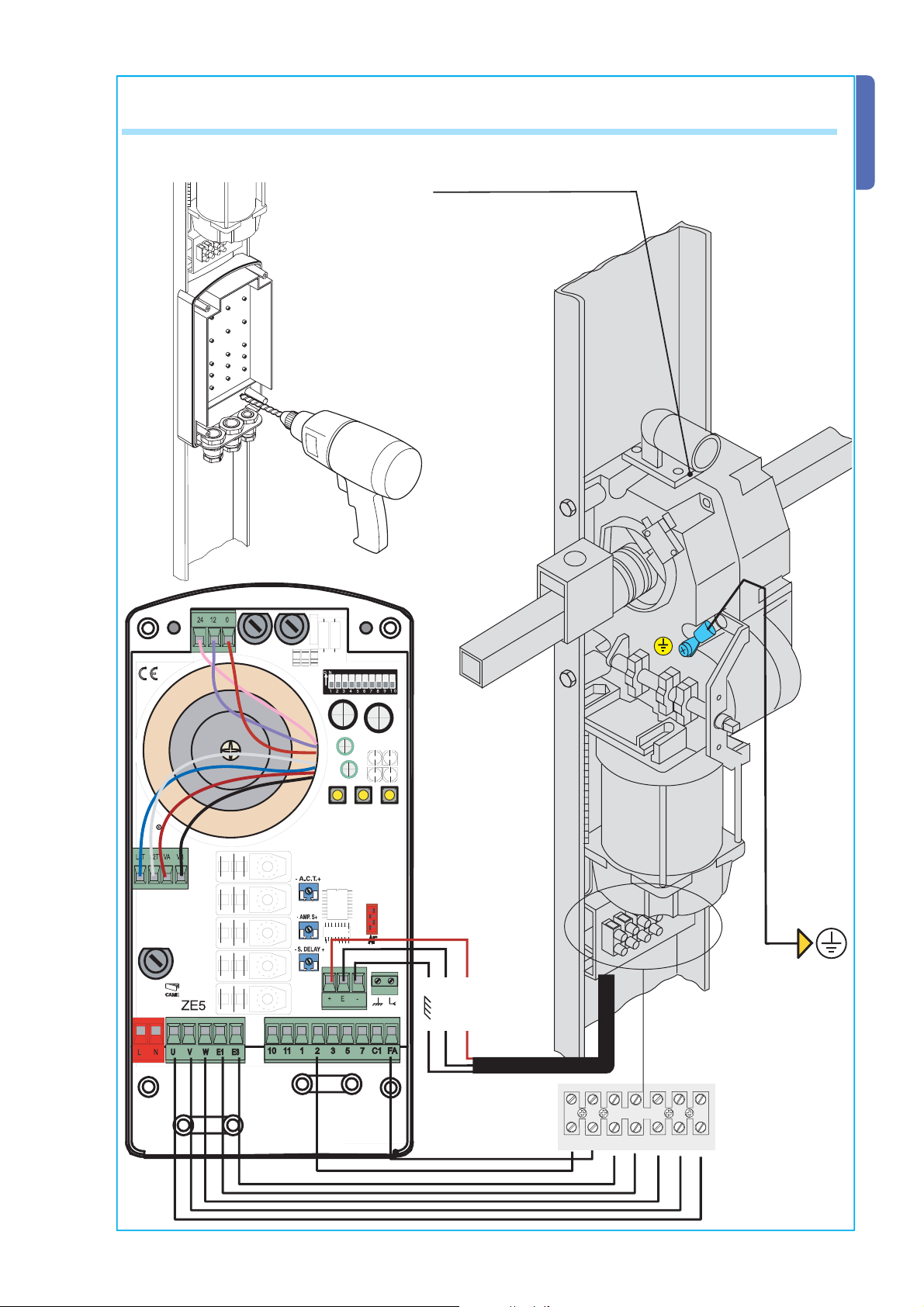
5.5 Pre-settings, Fixing the Electric Board to the Ground Guide (Art. 001E001) and
Ratiomotor Electric Connections
E306/E456 Ratiomotor
Use a ø 5 drill bit to bear a hole
observing the distance between
the centres as specifi ed in
paragraph 5.3, and secure the
control panel to the ground guide
using M 4x39 screws (provided).
ENGLISH
All the data and information contained herein is considered subject to change at any time and at our discretion.
Nero
Rosso
FA K E WVUF
5
Page 6

LINE
-ENC+
ZE7
CONTROL
5A
BOARD
FUSE 5x20
V
W
U
E1
E3
FA
5.6 Connections
ENGLISH
W
W
E1
E1
E3
10
11
10
N
L
L
N
U
V
230V (a.c.) power supply
230V (a.c.) max. 400 W single-phase motor
230V (a.c.) output in movement (e.g. fl ashing lamp - max. 25W)
101011111 2 3 5 7 C1C1FA
#!-%
230V (a.c.) courtesy lamp output (max. 60W)
24V (a.c.) (max. 20W) accessory power feed
5
24V-15W max. electric lock connection (set dip-switch 9 to OFF)
10
C1
FA
5
1
2
2
3
2
7
2
2
(24V-3W max.) “open door” signalling pilot light (set dip-switch 9 to ON)
Stop key (N.C.)
Opening key (N.O.)
Key for commands (N.O.) see selection on dip-switch 2 or closing key in the “sustained action” function (dip 6 to ON)
(N.C.) Contact “opening during closing”
Opening end-stop connection
Aerial connection
All the data and information contained herein is considered subject to change at any time and at our discretion.
N.B. All the usually closed (N.C.) contacts and keys should be deactivated via dip-switch or short-circuited.
6
Page 7

5.7 Dip-switch Functions
-ENC+
AF
ENGLISH
ON
1234
5678
910
ON
OFF
1 ON Automatic closing activated;
2 ON “Open-stop-close-stop” with key (2-7) and radio remote control (AF board inserted) activated;
2 OFF “Open-close” with key (2-7) and radio remote control (AF board inserted) activated;
3 ON “Opening only” with radio remote control (AF board inserted) activated;
4 ON “Pre-fl ashing during the opening and closing phases activated; after receiving an opening or closing
command, the fl ashing lamp connected on W-E1 fl ashes for 5 seconds prior to obeying the command.
5 ON Obstacle detection activated; with the motor stopped (door closed, open or after a total stop com-
mand), it prevents movement of any sort if the safety devices (e.g. photoelectric cells) detect an obstacle;
6 ON “Dead man” mode activated; the door functions by keeping the key pressed, key connected to (2-3) for
opening and (2-7) for closing, without including the remote control function;
7 OFF Reopening during closure activated; the safety device (2- C1) detects an obstacle during the door’s
closing phase and causes the door to invert movement until the door is completely open (7ON deactivated);
8 ON Encoder programming activated; it enables the opening and closing end-stop calibration procedure;
9 ON “Door Open” pilot light connected on terminals 10-5 activated; it signals the open position of the garage
door, and switches off when the door is closed.
9 OFF Electric lock connected to terminals 10-5 activated;
10 ON motor closing thrust increase activated.
5-10 ON Increased thrust during closing and surge function in operation.
All the data and information contained herein is considered subject to change at any time and at our discretion.
5.8 Trimmer Adjustments
A.C.T.
120"
- A.C.T.+
A.C.T. Trimmer = automatic closing time adjustment from a minimum of to a maximum
of 120s
- AMP. S+
AMP.S Trimmer = adjustment of door sensitivity during movement when obstacles are
detected.
- S. DELAY +
1"
S. DELAY Trimmer= adjusting operating time
7
Page 8

5.9 Encoder Programming
ENGLISH
IMPORTANT: READ INSTRUCTIONS CAREFULLY BEFORE PROCEEDING WITH PROGRAMMING.
Adjustment of stop micro-switch during opening
Release the ratiomotor and move the door manually to approximately 30 mm from the desired opening.
Rotate the cam until the micro-switch can be inserted and tighten the screw in the cam.
Relock the ratiomotor.
Cam
MM
End-Stop Micro-
Switch
Closing End-Stop
Set dip-switch 8 to ON: the LED indicator fl ashes
8 ON
ON
1234
5678
910
Press the “CLOSE” key and allow the garage door to arrive at the point of closing.
Press the “OP/CL” key: the LED indicator remains lighted to signal that the closing end-stop has been
recorded.
All the data and information contained herein is considered subject to change at any time and at our discretion.
8
Page 9

Opening End-Stop
Press “CH1/OP” and allow the door to open completely.
Press the “OP/CL” key: the LED indicator remains lit to signal the memorisation of the open end-stop.
Note: if the “CH1/OP” key is pressed twice within 15”, the slowing during closing mode is deactivated and the
“thrust reduction” function is automatically inserted, the function is made active when the door is about to
close. The LED indicator will resume fl ashing after having pressed the key for the second time.
Reset dip-switch 8 to OFF. Note: if the LED indicator begins to fl ash rapidly after resetting dip 8, it is necessary
to repeat the procedure from the beginning.
ENGLISH
8 OFF
ON
1234
5678
910
General notes during programming make sure to have memorised the closing end-stop fi rst, otherwise the
data will not remain memorised.
All the data and information contained herein is considered subject to change at any time and at our discretion.
9
Page 10

WARNING!
ACCES.
LINE
-A.C.T.+
-ENC+
1 2 3 4 5 6 7 8 9 10 11 12
05 06 07 08 09 V1 V2 V3
ZE7
OP./CL.
CONTROL
5A
C. BOARD
1,6A
CH1/OP.
CLOSE
BOARD
630mA
FUSE 5x20
AF
V
W
U
E1
EX
FA
5.10 Connecting Two Motors
Should two motors be installed, connect them in parallel.
ENGLISH
Use terminals U, V and W of the ZE5 control panel to connect both motors.
Note: Connect the encoder and the opening end-stop of a single motor.
#!-%
.EGRO
&! + % 76 5&
2OJO
2OT
2OUGE
2ED
2OSSO
3CHWARZ
.OIR
"LACK
.ERO
%
All the data and information contained herein is considered subject to change at any time and at our discretion.
0
24
12
ACCES.
C. BOARD
1,6A
630mA
ON
910
5678
1234
CH1/OP.
OP./CL.
WARNING!
L1T
VA
L2T
FUSE 5x20
LINE
5A
N
L
CLOSE
VB
-A.C.T.+
05 06 07 08 09 V1 V2 V3
1 2 3 4 5 6 7 8 9 10 11 12
-ENC+
AF
CONTROL
BOARD
-
+
E
ZE7
101011111 2 3 5 7 C1C1FA
567%% &!
&! + % 76 5&
10
Page 11

1 2 3 4 5 6 7 8 9 10 11 12
05 06 07 08 09 V1 V2 V3
OP./CL.
CH1/OP.
CLOSE
AF
6 Radio Remote Control Installation Procedure
Please read the following instructions carefully prior to installation:
- preparing the radio board (par. 6.1);
- transmitter encoding procedure (par. 6.2);
- control board code memorisation (par. 6.3).
6.1 Preparing the Radio Board (AF)
1) For transmitters with 433.92 AM frequencies
(TOP and TAM series) position the jumper on the
AF43S board, as illustrated.
2) The AF board should be MANDATORILY inserted only when the mains power is off, because the
motherboard only recognizes it when it is powered up
TOP TAM
“AF” Board
ENGLISH
Frequency/MHz Board Transmitter
FM 26.995 AF130 TFM
FM 30.900 AF150 TFM
AM 26.995 AF26 TOP
AM 30.900 AF30 TOP
AM 433.92 AF43S / AF43SM TAM / TOP
AM 433.92 AF43SR ATOMO
AM 40.685 AF40 TOUCH
6.2 Transmitter Encoding Procedure
Top quarzite series
All the data and information contained herein is considered subject to change at any time and at our discretion.
T262M - T264M - T2622M - T302M - T304M - T3022M common encoding procedure
0
1 mark a code (even for the archive)
0
Scheda base
/&&
/.
05 06 07 08 09 V1
1 2 3 4 5 6 7 8 9
AF
2 insert J code jumper
3 record it
4 unplug J jumper
Press P1 or P2 in sequence to record the code; on
the tenth impulse, a double beep will confi rm the
memorisation has taken place.
11
Page 12

ENGLISH
0 0
FIG.A
TOP
T262M - T302M
The fi rst code should be recorded by keeping the jumpers
positioned for channels 1 and 2 as in fi g. A; see fi g. B for any
further settings on different channels.
P1 = CH1 - P2 = CH3 P1 = CH3 - P2 = CH2
FIG.B
P1 = CH1 - P2 = CH4 P1 = CH3 - P2 = CH4
P1 = CH1
P2 = CH2
T264M - T304M
0 0
0 0
P1 = CH1
P2 = CH2
P3 = CH3
P4 = CH4
0 0
0 0
0
0
T2622M - T3022M
/&&
/.
1° Code
P1 = CH1
P2 = CH2
All the data and information contained herein is considered subject to change at any time and at our discretion.
2° Code
P3 = CH1
P4 = CH2
12
Page 13

Top Series
ENGLISH
0 0
0 0
0 0
T434M - T314M
TOP
D
T432M - T312M
Set the code to dip-switch C and the channel to D (P1 = CH1 and P2 = CH2, default
setting)
/. /. /. /.
P1
CH1
C
/. /. /. /.
P2
CH2 CH3 CH4
CH1 CH2 CH3 CH4
TOP
TOP
T432S - T432SA - T434MA - T432NA - T434NA
Set the code only
P1 = CH1
See instructions in the
package
P2 = CH2
P3 = CH3
P4 = CH4
CAME
C
Atomo Series
All the data and information contained herein is considered subject to change at any time and at our discretion.
Touch Series
TAM
T432 - T434 - T438 - TAM432SA
See instructions
sheet included in
the package
AT01 - AT02 - AT04
See the instructions sheet included
with the AF43SR board.
TCH 4024 - TCH 4048
TFM
T132 - T134 - T138
T152 - T154 - T158
See instructions sheet
included in the package
CAME
See instructions in the package
13
Page 14

6.3 Code Memorisation
-Keep the “CH1/OP” key pressed down on the control board (the LED indicator fl ashes);
ENGLISH
LED indicator flashes
!#4
- the code is sent by means of a transmitter key, and the LED indicator will remain lighted to signal that that
LED indicator is lit
!#4
7 Solving Problems
THE GARAGE DOOR DOES NOT MOVE:
- CHECK the 230 V AC power supply on terminals L-N.
- Check the fuses.
- Check the 24V power supply on terminals 10-11.
- Check the STOP key connection, if unused, short-circuit terminals 1-2.
- Repeat encoder programming.
THE GARAGE DOOR REMAINS OPEN:
- check the automatic closing function, (dip-switch 1).
- check if control devices are functioning properly.
- check if there is something obstructing the safety devices.
- check if all the n.c. contacts are set to on (if not being used).
All the data and information contained herein is considered subject to change at any time and at our discretion.
14
Page 15

8 Demolition and Disposal
In its premises, CAME CANCELLI AUTOMATICI S.p.A. implements an Environmental Management
System certifi ed in compliance with the UNI EN ISO 14001 standard to ensure environmental protection.
Please continue our efforts to protect the environment—which CAME considers one of the cardinal elements
in the development of its operational and market strategies—simply by observing brief recommendations
as regards disposal:
DISPOSAL OF PACKAGING – Our packaging is made up of various types of materials. Most of them
(paper, plastics, etc.) may be disposed of in normal garbage collection bins and can be recycled by disposing
of in specifi c recyclable material collection bins and disposal in authorized centres.
Prior to disposal, it is always advisable to check specifi c regulations in force in the place of disposal.
PLEASE DISPOSE OF PROPERLY!
PRODUCT DISPOSAL – Our products are made up of various types of materials. Most of them (aluminium,
plastics, iron, electric cables etc.) may be disposed of in normal garbage collection bins and can be recycled
by disposing of in specifi c recyclable material collection bins and disposal in authorized centres. Other
components (electric boards, batteries and radio remote controls, etc.), however, may contain hazardous
substances. They should therefore be removed and given to qualifi ed service companies for proper disposal.
Prior to disposal, it is always advisable to check specifi c regulations in force in the place of disposal.
PLEASE DISPOSE OF PROPERLY!
ENGLISH
9
Maker’s statement
MANUFACTURER’S DECLARATION
As per Enclosure II B of Machinery Directive 98/37/CE
Enclosed with the technical documentation (the original copy of the Declaration is available on request)
The representatives of
CAME Cancelli Automatici S.p.A.
via Martiri della Libertà, 15
31030Dosson di Casier - Treviso - ITALYtel
(+39) 0422 4940 - fax (+39) 0422 4941
internet: www.came.it - e-mail: info@came.it
Hereby declare, under their own respons ibility, that the product/s
called ...
All the data and information contained herein is considered subject to change at any time and at our discretion.
ZE5
… comply with the Italian National Legal Provisions that transpose
the
following Community Directives (where specifi cally applicable):
ACHINERY DIRECTIVE 98/37/CE
M
OW VOLTAGE DIRECTIVE 73/23/EEC - 93/68/EEC
L
ECTROMAGNETIC COMPATIBILITY DIRECTIVE 89/336/EEC - 92/31/EEC
L
IRECTIVE 1999/5/CE
R&TTE D
Also, they furthermore represent and warrant that the product/s that are the
subject of the present Declaration are manufactured in the respect of the
following main harmonized provisions:
PART 1 AND 2 MACHINERY SAFETY.
EN 292
EN 12453 INDUSTRIAL, COMMERCIAL AND OTHER CLOSING MECHANISMS.
EN 12445 I
EN 12978 S
EN 60335 - 1 S
EN 60204 - 1 MACHINERY SAFETY.
EN 61000 - 6 - 2 ELECTROMAGNETIC COMPATIBILITY.
EN 61000 - 4 - 4 E
EN 61000 - 4 - 5 E
IMPORTANT CAUTION!
It is forbidden to market/use product/s that are the subject of this declaration
before completing and/or incorporating them in total compliance with the
provisions of Machinery Directive 98/37/CE
Date of the present declaration 07/12/2001
NDUSTRIAL, COMMERCIAL AND OTHER CLOSING MECHANISMS.
AFETY DEVICES FOR POWER OPERATED DOORS AND GATES ....
AFETY IN APPARATUSES FOR HOME USE.
LECTROMAGNETIC COMPATIBILITY.
LECTROMAGNETIC COMPATIBILITY.
Signatures of the Representatives
TECHNICAL MANAGER
Mr. Gianni Michielan
MANAGING DIRECTOR
Mr. Paolo Menuzzo
15
Page 16

CAME UNITED KINGDOM LTD
UNIT 3, ORCHARD BUSINESS PARK
TOWN STREET, SANDIACRE
NOTTINGHAM - NG10 5BP - U.K.
Tel 0044 115 9210430
Fax 0044 115 9210431
ZE5v0.7_319T92 Vo1
 Loading...