

Page 1
SERIE Z |
Z
SERIES
/ SÉRIE Z |
BAUREIHE
Z |
SERIE Z
Documentazione
Tecnica
CANCELLI AUTOMATICI
ITALIANO
Descrizione
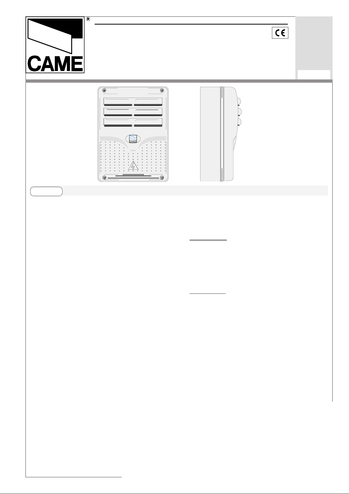
QUADRO COMANDO
CONTROL PANEL
ARMOIRE DE COMMANDE
SCHALTTAFEL
CUADRO DE MANDO
CARA TTERISTICHE GENERALI
Sicurezza
ZE4
S35
rev. 3.1
02/2001
©
CAME
CANCELLI
AUTOMATICI
319S35
Il quadro elettrico ZE4 è adatto al comando
di automazioni per porte basculanti della
serie EMEGA, alimentati a 230V con
potenza fino a 600W, frequenza 50÷60Hz.
Progettato e costruito interamente dalla
CAME S.p.A., risponde alle vigenti norme
UNI 8612. Contenitore in ABS con grado
di protezione IP54, dotato di presa per il
riciclo d’aria e completo di trasformatore.
Il circuito va alimentato con tensione di
230V (a.c.) nei morsetti L1-L2 e protetto in
ingresso con due fusibili da 5A, mentre i
dispositivi di comando a bassa tensione
sono protetti con fusibile da 2A.
La potenza complessiva degli
accessori (24V) non deve super
Le fotocellule possono essere collegate e
predisposte per:
-
Riapertura
in fase di chiusura (2-C1), le
fotocellule rilevando un ostacolo durante
la fase di chiusura della porta, provocano
l'inversione di marcia fino alla completa
apertura;
-
Stop totale
(1-2), arresto della porta con
l'esclusione del ciclo di chiusura automatica, per riprendere il movimento, agire
sulla pulsantiera o sul radiocomando;
Nota: Se un contatto di sicurezza normalmente chiuso (2-C1, 1-2) si apre, viene
segnalato dal lampeggio del LED di
segnalazione (n°7, pagina 8);
are i 20W.
Il quadro include la funzione di
spunto manovra. Questa
funzione
si attiva in fase d’inizio
apertura e chiusura del
portone.
-1-
Page 2

-
Rilevazione di presenza ostacolo.
A
secondi prima di iniziare la manovra.
motore fermo (portone chiuso, aperto o
dopo un comando di stop totale), impedisce qualsiasi movimento se i dispositivi di
sicurezza (es. fotocellule) rilevano un
ostacolo.
Accessori collegabili
-
Lampada di cortesia
illumina la zona di manovra, dopo un
comando di apertura, rimane accesa per
un tempo fisso di 5 minuti e 30 secondi,
collegarla ai morsetti E1-E3.
-
Lampada spia porta aperta
che segnala la posizione di apertura della
porta basculante, si spegne quando la
porta attiva il finecorsa chiude.
. Lampada che
. Lampada
- Tipo di comando
-apre-stop-chiude-stop con pulsante e/o
trasmettitore;
-apre-chiude con pulsante e/o trasmettito-
re;
-solo apertura con trasmettitore.
Regolazioni
- Tempo lavoro;
- Tempo chiusura automatica;
:
-
Elettroserratura 24V
morsetti 11-EB.
Altre funzioni
-
Chiusura automatica.
chiusura automatica si autoalimenta a
finecorsa apre. Il tempo prefissato
regolabile, è in ogni modo subordinato
all'intervento di eventuali accessori di
sicurezza e si esclude dopo un intervento
di "stop" o in mancanza d'energia elettrica.
-
"Uomo presente"
portone mantenendo premuto il pulsante
(esclude la funzione del radiocomando);
-
Finecorsa apre
l’ausilio del microinterruttore durante la
. Arresto della porta con
, collegarla ai
Il temporizzatore di
. Funzionamento del
fase di apertura, collegare il micro ai
morsetti F-FA e selezionare il dip n°9 in
OFF;
-
Prelampeggio
apertura o di chiusura, il lampeggiatore
collegato su W-E1, lampeggia per 5
-2-
. Dopo un comando di
Attenzione! Prima di intervenire
all’interno dell’apparecchiatura, togliere la tensione di linea.
Page 3
ENGLISH
GENERAL CHARACTERISTICS
Description of control panel
The ZE4 electric panel is suitable for controlling the automation of EMEGA series
230V garage-type doors with up to 600W
power and 50-60 Hz frequency.
Wholly designed and built by CAME
S.p.A., it meets UNI 8612 regulations in
force. ABS Case with an IP54 protective
level, with air recycling inlet and transformer.
The circuit requires 230V (a.c.) at terminal
blocks L1- L2 and the inlet is protected
with two 5A fuses, whilst the low voltage
command devices are protected by a 2A
fuse.
The accessories’ total wattage (24V) must
not exceed 20W.
The panel includes a manoeuvre pick-up
function. This function is activated during
the initial phase of the gate’s opening and
closing.
Safety
Photocells can be connected to obtain:
Re-opening during closure (2-C1), if the
photocells identify an obstacle while the
gate is closing, they will reverse the
direction of movement until the gate is
completely open;
-
Total stop (1-2), shutdown of gate
movement without automatic closing; a
pushbutton or radio remote control must
be actuated to resume movement.
N.B: If an NC safety contact (2-C1, 1-2) is
opened, the LED (n°7, pag.8) will flash to
indicate this fact;
-
Obstacle presence detection. When the
motor is stopped (gate is closed, open or
half-open after an emergency stop
command), the transmitter and the control
pushbutton will be deactivated if an
obstacle is detected by one of the safety
devices (for example, the photocells);
Accessories which can be connected
-
Courtesy Light. A light that illuminates the
manoeuvring zone; after an opening command, the light remains on for a fixed time
of 5 minutes and 30 seconds, connect it to
terminal block E1-E3.
-
Open gate pilot lamp. It is a light that indicates the garage-type door’s open posi-
tion and turns off when the gate activates
the closing end-stop.
-
24V electric lock, connect it to terminal
blocks 11-EB.
Other functions
-
Automatic closing. The automatic closing
timer is automatically activated at the end
of the opening cycle. The preset,
adjustable automatic closing time is
automatically interrupted by the activation
of any safety system, and is deactivated
after a STOP command or in case of
power failure;
-
"Operator present". Gate operates only
when the pushbutton is held down (the
radio remote control system is
deactivated);
-
Limit switch opening. The door stops with
the help of the microswitch during the
opening phase, connect the microswitch to
terminal blocks F-FA and switch dip n°9 to
OFF;
-
Pre-flashing. After an opening or closing
command, the flasher connected to the WE1 flashes for 5 seconds before beginning
the procedure;
-
Type of command:
-Open-stop-close-stop by button and
transmitter;
-Open-close by button and transmitter;
-Open only by transmitter.
Adjiustments
- Operating time;
- Automatic closure time.
Caution! Disconnect the unit from
the main power lines before carrying out
any operation inside the unit.
-3-
Page 4
FRANÇAIS
CARACTÉRISTIQUES GÉNÉRALES
Description armoire de commande
L’armoire électrique ZE4 sert à
commander l’automation des portes
basculantes de la série EMEGA,
alimentées à 230V avec une puissance
jusqu’à 600W, fréquence 50÷60Hz.
Conçu et construit entièrement par CAME
S.p.A., il est conforme aux normes NFP
25-362 en vigueur. Boîtier en ABS avec
degré de protection IP54, équipé d’une
prise pour le recyclage de l’air et d’un
transformateur.
Le circuit doit être alimenté avec une
tension de 230V (c.a.) aux bornes L1- L2
et doit être protégé à l’entrée par deux
fusibles de 5A, tandis que les dispositifs
de commande à basse tension sont
protégés par un fusible de 2A.
La puissance totale des accessoires (24V)
ne doit pas dépasser 20W.
L’armoire est prévu avec la fonction de
courant supérieur de démarrage. Cette
fonction s’active en début d’ouverture et
de fermeture de la porte.
Sécurité
Il est possible de brancher des
photocellules et de les programmer pour:
Réouverture
C1), les cellules photoélectriques
provoquent l'inversion de marche jusqu'à
l'ouverture complète si elles relèvent un
obstacle durant la phase de fermeture du
portail;
Stop total
désactivation d’un éventuel cycle de
fermeture automatique; pour activer de
nouveau le mouvement, il faut agir sur les
boutons-poussoirs ou sur la radiocommande.
Remarque
(n°7, pag.8) qui clignote indique qu'un
contact de sécurité normalment fermé (2C1, 1-2) s'ouvre.
Détection de présence obstacle
moteur est arrête (portail fermé, ouver t ou
semi-ouvert, cette position est obtenue
avec une commande de stop total), annule
toute fonction de l'émetteur ou du boutonpoussoir en cas d'obstacle détecté par les
dispositifs de sécurité (ex. Photocellules);
en phase de fermeture (2-
(1-2), arrêt du portail et
: Le voyant de signalisation
. Quand le
Accessoires pouvant être branchés
Lampe passage
zone de manoeuvre, après une commande d’ouverture elle reste allumée pour
une durée fixe de 5 minutes et 30 secondes, la brancher aux bornes E1-E3.
- Lampe por te ouverte
la position d’ouverture de la por te
basculante, elle s’éteint quand la porte
active l’interrupteur de fin de course
fermeture.
Serrure électrique 24V
bornes 11-EB.
Autres functions
Fermeture automatique.
risateur de fermeture automatique est
autoalimenté à la fin du temps de la
course en ouverture. Le temps réglable
est programmé, cependant, il est
subordonné à l’intervention d’éventuels
accessoires de sécurité et il est exclu
après une intervention de “stop” ou en cas
de coupure de courant;
“Homme mort”
portail en maintenant appuyé le boutonpoussoir (exclut la fonction de la
radiocommande);
- Interrupteur fin de course ouverture
Arrêt de la por te à l’aide du microcontact
durant la phase d’ouverture, brancher le
microcontact aux bornes F-FA et mettre le
commutateur à bascule n° 9 sur OFF;
Pré-clignotement
d'ouverture ou de fermeture, le clignotant
branché sur W-E1, clignote pendant 5
secondes avant de commencer la
manoeuvre;
- Type de commande
-ouvre-stop-ferme-stop pour bouton et
émetteur;
-ouvre-ferme pour bouton et émetteur;
-seulement ouverture pour émetteur.
Réglages
- Temps de fonctionnement;
- Temps de fermeture automatique.
. Lampe qui illumine la
. Lampe qui signale
, la brancher aux
Le tempo-
. Fonctionnement du
.
. Après une commande
:
Attention! Avant d’intervenir à
l’intérieur de l’appareillage, couper la
tension de ligne.
-4-
Page 5

DEUTSCH
ALLGEMEINE MERKMALE
Beschreibung des Steuergeräts
Die elektrische Schalttafel ZE4 ist für die
Steuerung automatischer Schwingtore der
Serie EMEGA, mit einer Versorgung von
230V, Leistung bis 600W und Frequenz
50÷60, geeignet.
Sie ist von der CAME S.p.A. entworfen
und erstellt und entspricht den geltenden
Richtlinien UNI 8612. Der Kasten ist in
ABS, Schutzgrad IP54 mit Anschluß für
die Luftrückführung und Transformator.
Die Versorgung des Stromkreises erfolgt
mit 230V (a.c.) über die Klemmen L1-L2
und ist am Eintritt durch 2 Sicherungen
von 5A geschützt. Die Steuervorrichtungen mit Unterspannung sind mit einer 2ASicherung ausgestattet.
Die Gesamtleistung des Zubehörs (24V)
darf 20W nicht überschreiten.
Die Schalttafel umfaßt die Anlassfunktion.
Diese Funktion startet bei Beginn des
Schließ- oder Öffnungsvorganges des Tores.
Sicherheitsvorrichtungen
Die Lichtschranken können für folgende
Funktionen angeschlossen bzw.
vorbereitet werden:
Wiederöffnen beim Schließen (2-C1), die
Lichtschranken ermitteln ein Hindernis
während des schließens vom Tor und
lösen die Umkehr der Laufrichtung vom
Tor aus, bis dieses wieder vollständig
geöffnet ist;
Totalstop (1-2), sofortiger Stillstand des
Tores mit Ausschluß eventueller
Schließautomatik: Fortsetzung des
Torlaufs über Dr ucktaster- bzw.
Funksendersteuerung;
Hinweis: Wenn sich ein normalerweise
geschlossener (NC) Sicherheitskontakt (2C1, 1-2) öffnet, wird dies durch Blinken
der Kontrolleuchte (n°7 - S.8) angezeigt;
Ermittlung eventuell vorhandener
Hindernisse. Bei stillstehendem Motor (Tor
geschlossen, geöffnet oder durch eine
Totalstop-Steuerung halb geöffnet) wird
bei durch die Sicherheitsvorrichtungen
(z.B.:Lichtschranken) erfaßtem Hindernis
jede Sensor-oder Drucktasterfunktion
annulliert.
Anschließbares Zubehör
Torbeleuchtung. Nachdem der Befehl
zum Öffnen des Tors gegeben worden ist,
bleibt das Licht, das den Manöverbereich
am Tor beleuchtet, für eine vorgegebene
Zeit von 5 Minuten und 30 Sekunden
eingeschaltet, mit den Klemmen E1-E3
verbinden.
Kontrollampe bei geöffnetem Tor. Die Kontrollampe zeigt an, daß das Tor geöffnet ist
und erlischt, wenn das Tor den
Endanschlag des Schließvorganges erreicht hat.
Elektrische Verriegelung 24V, mit den
Klemmen 11-EB verbinden.
Andere Wahlfunktionen
Schließautomatik. Der Schließautomatik-
Zeischalter speist sich beim Öffnen am
Ende der Torlaufzeit selbst . Die
voreingestellte Zeit ist auf jeden Fall
immer dem Eingriff eventueller
Sicherheitsvorrichtungen untergeordnet
und schließt sich nach einem “Stop”-
Eingriff bzw. bei Stromausfall selbst aus;
“Bedienung vom Steuerpult”. Torbetrieb
durch Drucktasterbetätigung (Funkfernsteuerung ausgeschlossen);
Endanschlag des Öffnungsvorganges.
Blockierung des Tores während des
Öffnungsvorganges in jeder gewünschten
Position durch Bedienung des Mikroschalters; den Mikro an die Klemmen F-FA
anschließen und Dip Nr. 9 in Position OFF
eingeben.
Vorblinken. Nachdem der Befehl zum
Öffnen oder Schließen gegeben worden
ist, blinkt das Blinklicht, das an W-E1
angeschlossen ist, zunächst 5 Sekunden,
bevor das Manöver beginnt;
Befehlsarten:
-
-Öffnen-Stop-Schließen-Stop für Druckknopf und Sender;
-Öffnen-Schließen für Druck. und Sender;
-nur Öffnen für Sender.
Einstellungen
- Laufzeit;
- Zeit für das automatische Schließen;
Achtung! Das Gerät vor Eingriffen
im inneren spannungsfrei schalten.
-5-
Page 6

ESPANOL
CARACTERISTICAS GENERALES
Descripción cuadro de mando
El cuadro eléctrico ZE4 es idóneo para el
control de automatizaciones para puertas
basculantes de la serie EMEGA,
alimentados a 230V, con potencia de
hasta 600W, frecuencia 50÷60Hz.
Diseñado y fabricado completamente por
CAME S.p.A., responde a las normas UNI
8612 vigentes. Caja de ABS con grado de
protección IP54, con toma para
recirculación de aire y transformador.
El circuito se alimenta con tensión de
230V (c.a.) en los bornes L1- L2 y está
protegido en entrada con dos fusibles de
5A, mientras que los dispositivos de baja
tensión están protegidos con fusible de
2A.
La potencia total de los accesorios (24V)
no debe superar los 20W.
El cuadro incluye la función de punto de
arranque. Dicha función se activa durante
el comienzo de apertura y cierre de la
puerta.
Seguridad
Il est possible de brancher des
photocellules et de les programmer pour:
Réouverture en phase de fermeture (2-
C1), les cellules photoélectriques
provoquent l'inversion de marche jusqu'à
l'ouverture complète si elles relèvent un
obstacle durant la phase de fermeture du
portail;
Parada total (1-2), parada de la puerta
excluyendo el posible ciclo de cierre
automático, para reactivar el movimiento
es preciso actuar en el teclado o en el
mando a distancia;
Nota: La apertura de un contacto de
seguridad normalmente cerrado (2-C1, 2C3, 1-2) es señalada por medio del
destello del LED de señalización (n°7 pág.8).
Detección de presencia obstáculo. Con el
motor parado (puerta cerrada, abier ta o
en posición semi-abier ta obtenida a través
de un comando de stop total), anula
cualquier función del transmisor o del
botón en caso de obstáculo detectado por
los dispositivos de seguridad (por ejemplo:
fotocélulas).
Accesorios conectables
Luz de cortesía. Lámpara que ilumina la
zona de maniobra; tras un mando de apertura permanece encendida por 5 minutos
y 30 segundos, conéctela a los bornes
E1-E3.
Indicador luminoso de puerta abier ta.
Lámpara que indica que la puerta
basculante está abierta; se apaga cuando
la puerta activa el final de carrera de
cierre.
Electrocerradura 24V, conéctela a los
bornes 11-EB.
Otras funciones
Cierre automático. El tempor izador de
cierre automático se autoalimenta en finde-tiempo carrera en fase de apertura. El
tiempo prefijado regulable, sin embargo,
está subordinado a la intervención de
posibles accesorios de seguridad y se
excluye después de una intervención de
parada o en caso de falta de energía
eléctrica;
“Hombre presente". Funcionamiento de
la puerta manteniendo pulsada la tecla
(excluye la función del mando a distancia);
Final de carrera apertura. Paro de la
puerta con la ayuda del microinterruptor
durante la apertura; conecte el micro a los
bornes F-FA y coloque el dip n°9 en OFF;
Intermitencia. Después de un mando de
apertura o cierre, la lámpara intermitente
conectada en W-E1, parpadea por 5
segundos antes de comenzar la maniobra;
Tipo de mando:
-
-abrir-stop-cerrar-stop para botón y
transmisor;
-abrir-cerrar para botón y transmisor;
-sólo apertura para transmisor.
Regulaciones
- Tiempo de cierre automático;
- Tiempo de trabajo.
¡Atención! Antes de actuar dentro
del aparato, quitar la tensión de línea.
-6-
Page 7

P A GINA LASCIA TA INTENZIONALMENTE BIANCA
THIS P A GE LEFT INTENTIONALLY BLANK
DIE SEITE WURDE ABSICHLICH LEER GELASSEN
NOUS AV ONS LAISSÉ EXPRÈS CETTE PAGE BLANCHE
P Á GINA DEJADA EN BLANCO INTENCIONALMENTE
-7-
Page 8

SCHEDA B ASE -
MOTHERBOARD
- CARTE BASE -
GRUNDPLATINE
- TARJETA BASE
1010
10
1010
che fuoriescono dalla scheda sui connettori del condensatore del 1° motore e i
fili rossi sul condensatore
del 2° motore (con porta a
Nota: collegare i fili neri
FRENO
234
1
01224
FUSIBILE
FUS.IBILE
LINEA 5A
CENTRALINA
2A
33
3
33
22
2
22
SPUNTO
Nero
Black
Noir
Schwarz
Negro
55
44
5
4
55
44
T.L. T.C.A.
77
7
77
10
89
Rosso
Red
Rouge
66
6
66
Rot
Rojo
doppio motore).
NB: connect the black wires
coming out of the board to
the connectores of the first
motor’s condenser and the
red wires to the second
motor’s condenser (if the gate
has two motors).
Note: connecter les fils
noirs qui sortent de la carte
sur les connexteurs du
condensateur du 1er moteur
88
8
88
et les fils rouges sur le
condensateur du 2e moteur
99
9
21 34567
ON
99
(avec porte à double
moteur).
FUS.IBILE
LINEA 5A
1 Morsettiere di collegamento
QUAD RO COMA NDO
ZE4
11
1
11
COMPONENTI PRINCIPALI
2 Fusibili di linea 5A
3 Fusibile centralina 2A
4 Trimmer di regolazione tempo lavoro
5 Trimmer di regolazione tempo di chiusura automatica
6 Pulsante memorizzazione codice
7 LED segnalazione
8 Selettore funzioni (vedi pag.12)
9 Innesto scheda radiofrequenza
10 Limitatore di coppia motore (pag.15)
-8-
Hinweis: Die schwarzen
Kabel, die von der Karte
wegführen, an die Verbinder
am Kondensator vom 1.
Motor anschließen, die roten
Kabel an den Kondensator
vom 2. Motor (bei Toren mit
doppeltem Motor).
Nota: conectar los hilos
negros que salen de la
tarjeta en los conectores
del condensador del 1°
motor y los hilos rojos en
el condensador del 2°
motor (con puerta de doble
motor).
ITALIANO
Page 9

MAIN COMPONENTES
1 Terminal block for external conections
2 Line fuse, 5A
3 Fuse on central control unit, 2A
4 Trimmer for adjustment operating time
5 Trimmer for adjustment automatic closing
6 Radio-code save button
7 Signal LED
8 10-dip function switch (see pag.13)
9 Socket AF radiofrequency board
10 Motor torque limiter (pag.15)
ENGLISH
PRINCIPAUX COMPOSANTS
1 Plaque à bornes de connexion
2 Fusible de ligne 5A
3 Fusible de logique de commande 2A
4 Trimmer de réglage temps de fonction.
5 Trimmer de réglage fermeture automatique
6 Bouton-poussoires mémorisation code radio
7 LED de signalisation
8 Selecteur de fonctions (voir pag.13)
9 Branchement carte radiofréquence AF
10 Limiteur de couple moteur (pag.15)
HAUPTKOMPONENTEN
1 AnschlußKlemmenleiste
2 Hauptsicherung 5A
3 Schaltkastensicherung 2A
4 Trimmer zur Einstellung Laufzeit
5 Trimmer zur Einstellung der Schließautomatik
6 Knöpfe zum Abspeicher der Radiocodes
7 LED Kontrolleuchte zur Anzeige
8 Wählschalter für Funktionen mit 10 Dip (sehen S.14)
9 Steckanschluß Funkfrequenze-Platine AF
10 Drehmomentbegrenzer des Motors (Seite 15)
FRANÇAIS
DEUTSCH
PRINCIPALES COMPONENTES
1 Caja de bornes para las conexiónes
2 Fusible de línea 5A
3 Fusible lógica de mando 2A
4 Trimmer de regulación tiempo trabajo
5 Trimmer de regulación tiempo cierre automático
6 Tecla de memorización del código radio
7 LED de señal
8 Selector de funciones (vedas pág.14)
9 Conexión tarjeta radiofrecuencia AF
10 Limitador de par motor (pág.15)
ESPANOL
-9-
Page 10

L1
L2
U
W
V
COLLEGAMENTI ELETTRICI -
ELEKRISCHE ANSCHLÜSSE -
L1 L2 U V W E1E3 EB 10 11 1 2 7 C1 5 FA F
Alimentazione 230V (a.c.)
230V (a.c.) power input
Alimentation 230V (c.a.)
Stromversorgung 230V (Wechselstrom)
Alimentación 230V (a.c.)
Motore monofase 230V (a.c.) max. 600W
230V (a.c.) single-phase motor max. 600W
Moteur monophasé 230V (c.a.)max. 600W
Einphasenmotor 230V (Wechselstrom) max. 600W
Motor monofásico 230V (a.c.) max. 600W
ELECTRICAL CONNECTIONS -
CONEXIONES ELÉCTRICAS
BRANCHEMENTS ÉLECTRIQUES
W
E1
E1
E3
Uscita 230V (a.c.) in movimento
(es. lampeggiatore - max. 25W)
230V (a.c.) output in motion
(e.g. flashing light - max. 25W)
Sortie 230V (c.a.) en mouvement
(ex. branchement clignotant - max. 25W)
Ausgang 230V (Wechselstrom) in Bewegung
(z.B. Blinker-Anschluß - max. 25W)
Salida de 230V (a.c.) en movimento
(p.ej. conexión lámpara intermitente - max. 25W)
Uscita 230V (a.c.)
lampada cortesia - max. 60W
Output 230V (a.c.)
max. 60W - courtesy lamp
Sortie 230V (c.a.)
lampe d’éclairage - max. 60W
Ausgang 230V (Wechselstrom)
Torbeleuchtung
- max. 60W
Salida de 230V (a.c.)
lámpara cortesía - max. 60W
UVWE1
UV
WE1
E3
10
11
-10-
Alimentazione accessori 24V (a.c.) max. 20W
24V (a.c.)Powering accessories, max 20W
Alimentation accessoires 24V (c.a.) max. 20W
Zubehörspeisung 24V (Wechselstrom) max. 20W
Alimentación accesoios 24V (a.c.) max. 20W
Page 11

EB
11
10
5
1
2
Collegamento elettroserratura 24V - 15W max.
Connection for electric blocking system 24V - 15W max.
Connexion du bloc de fermeture électrique 24V - 15W max.
Elektro-Schließsperre-Anschluß 24V - max. 15W
Conexión electrobloqueo 24V - 15W máx.
Lampada spia (24V-3W max.) "porta aperta"
(24V-3W max.) "gate-opened" signal lamp
Lampe-témoin (24V-3W max.) "portail ouverture"
Signallampe (24V-3W max.) "Tor Öffnen"
Lámpara indicadora (24V-3W max.) "puerta abierta"
Pulsante stop (N.C.)
Pushbutton stop (N.C.)
Bouton-poussoir arrêt (N.F.)
Stop-Taste (Ruhekontakt)
Pulsador de stop (N.C.)
2
7
2
C1
F
FA
Contatto radio e/o pulsante per comando
(vedi dip pag. 12)
Contact radio and/or button for control
(see dip pag. 13)
Contact radio et/ou poussoir pour commande
(voir dip pag. 13)
Funkkontakt und/oder Taste Steuerart
(sehen Dip Seite 14)
Contacto radio y/o pulsador para mando
(vedas dip pág. 14)
Contatto (N.C.) di «riapertura durante la chiusura»
Contact (N.C.) for «re-opening during the closing»
Contact (N.F.) de «réouverture pendant la fermeture»
Kontakt (Ruhekontakt) «Wiederöffnen beim Schliessen»
Contacto (N.C.) para la «apertura en la fase de cierre»
Collegamento finecorsa apre (N.C.)
(N.C.) Connection limit switch opens
Connexion fin de course ouverture (N.F.)
Anschluß Endschallter Öffnung (Ruhekontakt)
Conexión fin de carrera apertura (N.C.)
Collegamento antenna
Antenna connection
Connexion antenne
Antennenanschluß
Conexión antena
-11-
Page 12

SELEZIONI FUNZIONI -
FUNKTIONSWAHL
SELECTION OF FUNCTIONS
- SELECCIÓN DE LAS FUNCIONES
ITALIANO
- SÉLECTION FONCTIONS
DIP-SWITCHES (1-10)
8910
2
1 34567
ON
ON
OFF
1 ON Chiusura automatica attivata;
(1OFF - disattivata)
2 ON "Apre-stop-chiude-stop" con
pulsante (2-7) e radiocomando
(scheda AF inserita) attivata;
2 OFF "Apre-chiude" con pulsante (2-7) e
radiocomando (scheda AF inserita) attivata;
3 ON "Sola apertura" con radiocomando
(scheda AF inserita) attivata;
(3OFF - disattivata)
4 ON Prelampeggio attivato; (4OFF -
disattivato)
5 ON Rilevazione di presenza ostacolo
attivata; (5OFF - disattivata)
6 OFF “Uomo presente" (esclude il
funzionamento del radiocomando)
disattivato; (6 ON - attivato)
T.L. T.C.A.
FUSIBILE
CENTRALINA
2A
FUS.IBILE
LINEA 5A
21 345678910
ON
FUS.IBILE
LINEA 5A
QUADRO C OM A NDO
ZE4
7 OFF Riapertura in fase di chiusura
attivata; con dispositivo di
sicurezza collegato ai morsetti 2C1, (se non viene utilizzato il
dispositivo, selezionare il dip in
ON)
8 OFF Stop totale attivata con dispositivo
di collegato ai morsetti 1-2, (se
non viene utilizzato il dispositivo,
selezionare il dip in ON)
9 OFF Finecorsa apre attivata; con
dispositivo (microinterruttore)
-12-
collegato ai morsetti F-FA, (se non
viene utilizzato il dispositivo,
selezionare il dip in ON)
10 Non connesso, tenere il dip in
posizione «OFF»
Page 13

ENGLISH FRANÇAIS
1 ON Automatic closure activated;
(1OFF - deactivated)
2 ON "Open-stop-close-stop" with button
(2-7) and radio control (AF board
inserted) activated;
2 OFF "Open-close" with button (2-7) and
radio control (AF board inserted)
activated;
3 ON "Only opening" with radio control
(AF board inserted) activated;
(3OFF - deactivated)
4 ON Pre-flashing activated; (4OFF -
deactivated)
5 ON Obstacle detection device
1 ON Fermeture automatique activée;
(1OFF-désactivée)
2 ON "Ouvre-stop-ferme-stop" avec
bouton (2-7) et commande-radio
(carte AF insérée) activée;
2 OFF "Ouvre-ferme" avec bouton (2-7)
et commande-radio (carte AF
insérée) activée;
3 ON "Soulement ouverture" avec
commande-radio (carte AF
insérée) activée; (3OFFdésactivée)
4 ON Preclignotement activée; (4OFF -
désactivée)
5 ON Dispositif de détection d'obstacle
activated; (5OFF - deactivated)
6 OFF “Operator present" (radio remote
control is deactivated when
function is selected) deactivated;
(6ON - activated)
7 OFF Re-opening in closing phase
activated; connect the safety
device on terminals 2-C1, (if not
used, set the dip-switch to ON)
8 OFF Total stop activated; connect the
safety device on terminals 1-2, (if
not used, set the dip-switch to ON)
9 OFF Limit switch opening activated;
with the device (microswitch)
activée; (5OFF-désactivée)
6 OFF "Homme mort" (exclut la fonction
radiocommande) désactivée;
(6ON-activée)
7 OFF Réouverture en phase de
fermeture activée; relier le
dispositif de sécuritè aux bornes 2C1; (s'il n'est pas utilisé,
positionner l'interrupteur à
positions multiples sur ON)
8 OFF Stop total activée relier le
dispositif de sécurite aux bornes 12, (s'il n'est pas utilisé, positionner
l'interrupteur à positions multiples
sur ON)
connected to terminal blocks F-FA,
(if the device is not used, switch
dip to ON)
10 Not used, keep the dip in position
"OFF"
9 OFF Interrupteur de fin de course
ouverture activé; avec le dispositif
(microcontact) branché aux bornes
F-FA, (mettre le commutateur à
bascule sur ON si le dispositif
n’est utilisé)
10 Not used, keep the dip in position
"OFF"
-13-
Page 14

DEUTSCH
ESPANOL
1 ON Schließautomatik aktiviert; (1OFF
- deaktiviert)
2 ON "Öffnen-Stop-Schließen-Stop" mit
Druckknopf (2-7) und
Fernsteuerung (Karte AF
eingesteckt) aktiviert;
2 OFF "Öffnen-Schließen" mit Druckknopf
(2-7) und Fernsteuerung (Karte AF
eingesteckt) aktiviert;
3 ON "nur Öffnen" mit Fernsteuerung
(Karte AF eingesteckt) aktiviert;
(3OFF - deaktiviert)
4 ON Vorblinken aktiviert; (4OFF -
deaktiviert)
5 ON Hindemisaufnahme aktiviert;
(5OFF - deaktiviert)
6 OFF Bedienung vom "Steuerpult" (bei
Wahl dieser Betriebsart wird die
Funkfernsteuerung
ausgeschlossen) deaktiviert;
(6ON - aktiviert);
7 OFF Wiederöffnen beim Schließen
aktiviert; schließen Sie die
Sicherheitsvorrichtung an die
Klemmen 2-C1 an, falls nicht
verwendet, schalten Sie den Dip
auf ON;
1 ON Cierre automático activado;
(1OFF-desactivado)
2 ON Abrir-stop-cerrar-stop" con botón
(2-7) y radiocontrol (tarjeta AF
conectada) activado;
2 OFF "Abrir-cerrar" con botón (2-7) y
radiocontrol (tarjeta AF conectada)
activado;
3 ON "Solo apertura" con radiocontrol
(tarjeta AF conectada) activado;
(3OFF-desactivado)
4 ON Pre-intermitencia activado;
(4OFF-desactivado)
5 ON Detección del presencia obstáculo
activado; (5OFF-desactivado);
6 OFF "Hombre presente" (escluye la
función del mando de radio)
desactivado; (6ON - activado)
7 OFF Reapertura en la fase de cierre
activada; conecte el dispositivo
de seguridad a los bornes 2-C1,
(si no se utiliza, poner el dip en
ON);
8 OFF Parada total activado; conecte el
dispositivo de seguridad a los
8 OFF Totalstop aktiviert schließen Sie
die Sicherheitsvorrichtung an die
Klemmen 1-2 an, (falls nicht
verwendet, schalten Sie den Dip
auf ON)
9 OFF Endanschlag des
Öffnungsvorganges aktiviert;
mittels des Mikroschalters, der an
die Klemmen F-FA angeschlossen
ist (sollte die Vorrichtung nicht
eingesetzt werden, Dip in Position
ON wählen)
10 Nicht in Gebrauch; lassen Sie den
-14-
Dip-Schalter auf "OFF" stehen;
bornes 1-2, (si no se utiliza, poner
el dip en ON);
9 OFF Final de carrera apertura
activada; con dispositivo
(microinterruptor) conectado a los
bornes F-FA, (se no se utiliza el
dispositivo, coloque el dip en ON);
10 No se utiliza, mantenga el dip en
posición "OFF".
Page 15

REGOLAZIONI -
REGOLAZI ONE TRIMMERS
TRIMMERS ADJUSTMENT
RÉGLAGE TRIMMERS
EINT ELLUNG TRIM MER S
REGULACIÓN TRIMMERS
T.L. T.C.A.
FUSIBILE
CENTRALINA
2A
FUS.IBILE
LINEA 5A
FUS.IBILE
LINEA 5A
QUADRO C OM ANDO
ZE4
ADJUSTMENTS
21 345678910
ON
- RÉGLA GES -
EINSTELLUNGEN
ITALIANO
Trimmer T.L.
lavoro da un minimo di 15 secondi a un
T.L.
T.C.A.
massimo di 80 secondi.
Trimmer T.C.A.
chiusura automatica da un minimo di 1
secondo a un massimo di 120 secondi.
ENGLISH FRANÇAIS
- REGULACIONES
= Regolazione tempo di
= Regolazione tempo di
Trimmer T.L.
= Adjusts of operating time
from a minimum of 15 seconds to a
maximum of 80 seconds.
Trimmer T.C.A.
= Adjusts automatic
closing time from a minimum of 1 second
to a maximum of 120 seconds.
Trimmer T.L.
= Laufzeit mit mindestens
15 Sek. und höchstens 80 Sek. eingestellt
werden kann.
Trimmer T.C.A.
= Timer, auf dem die
Verzögerung für das automatische
Schließen mit mindestens 1 Sekund und
höchstens 120 Sekunden eingestellt
werden kann.
LIMITATORE DI COPPIA MOTORE /
Per variare la
coppia motrice, spostare il
faston indicato
(con filo di
colore nero) su
una delle 4
posizioni; 1
min. - 4 max
DREHMOMENTBEGRENZER DES MOTORS
To vary the
motor torque,
move the
indicated faston
to one of the
four positions:
1=min, 4=max
MOTOR TORQUE LIMITER
Pour varier le
couple du
moteur,
déplacer le
connecteur
indiqué sur
l'une des 4
positions; 1
min. - 4 max.
Trimmer T.L.
= Réglage du temps de
fonctionnement d’un minimum de 15
secondes à un maximun de 80 sec.
Trimmer T.C.A.
= Réglage du temps de
fermeture automatique d'un minimum de 1
seconde à un maximun de 120 sec.
ESPANOLDEUTSCH
Trimmer T.L.
= Regulación tiempo de
trabajo, desde un mínimo de 15 segundos
hasta un máximo de 80 seg.
Trimmer T.C.A.
= Regulación del tiempo
de cierre automático, desde un mínimo de
1 segundo hasta un máximo de 120
segundos.
/ LIMITEUR DE COUPLE MOTEUR
/LIMITADOR DE PAR MOTOR
Zur Änderung
des MotorDrehmoments
den angegebenen Faston auf
eine der 4
Stellungen
positionieren: 1
Para variar el
par motor,
desplazar el
faston
indicado hasta
una de las 4
posiciones; 1
mín. - 4 máx.
min. - 4 max.
L2T
234
1
01224
L1T L2T CT VS 24 12 0
L1T
SPUNTO
234
1
L1T
L2T
01224
VS
T.L. T.C.A.
FUSIBILE
CENTRALINA
2A
FUS.IBILE
LINEA 5A
21 345 678910
ON
QUADRO COMANDO
FUS.IBILE
LINEA 5A
ZE4
-15-
Page 16

ISTRUZIONI MONTAGGIO QUADRO S4340 -
INSTRUCTIONS MONT AGE ARMOIRE S4340
MONTAGEANWEISUNGEN SCHAL TTAFEL S4340 -
1
Assemblare le cerniere a pressione
Assemble the hinges by pressure
Assembler les charnières à pression
Setzen Sie die Druckscharniere zusammen.
Ensamblar las bisagras a presión
15 mm~
scorrono per ruotare
they must slide in order to turn
elles glissent pour tourner
laufen zum Drehen
deslizan para girar
ASSEMBLY INSTRUCTIONS S4340 PANEL
INSTRUCCIONES MONTAJE CUADRO S4340
!!
2
Inserire le cerniere nella scatola (sul lato
destro o sinistro a scelta) e fermarle con le
viti e le rondelle in dotazione
Insert the hinges (on the right or left side,
according to choice) and secure using the
screws and washers supplied
Placer les charnières (du côté droit ou
gauche au choix) et les fixer avec les vis et
les rondelles fournies de série
Setzen Sie die Scharniere ein (je nach
Wunsch auf der rechten oder linken Seite)
und befestigen Sie sie mit den mitgelieferten
Schrauben und Unterlegscheiben
Introducir las bisagras (en el lado izquierdo o
derecho, a placer) y fijarlas con los tornillos
y las arandelas suministradas a tal efecto
295 mm
215 mm
3
Posizionare e fissare la scatola del
quadro
Position and secure the control
panel housing
Placer et fixer la boîte de l'armoire
Plazieren Sie das Gehäuse der
Schalttafel und befestigen Sie es.
Colocar y sujetar la caja del cuadro
-16-
Inserire a scatto il coperchio sulle cerniere,
4
chiuderlo e fissarlo con le viti in dotazione
Snap the cover onto the hinges and secure
using the screws supplied.
Assembler par encliquetage le couvercle sur
les charnières et fixer le couvercle avec les vis
fournies de série
Lassen Sie den Deckel in den Scharnieren
einrasten und befestigen Sie ihn mit den
mitgelieferten Schrauben.
Introducir la tapa en las bisagras hasta oír un
chasquido y fijar la tapa con los tornillos
suministrados a tal efecto.
Page 17

CONTENITORE IN ABS /
ABS-GEHÄUS
C
ASING IN
ABS
/
CAJA DE ABS
001S4340
/ BOÍTIER EN ABS
320 mm
240 mm
120 mm
145 mm
-17-
Page 18

INSTALLAZIONE DEL RADIOCOMANDO -
INSTALLATION DER RADIOSTEUERUNG
ZE4
RADIO CONTROL INSTALLATION
-
INSTALACIÓN DEL RADIOMANDO
-
INSTALLATION DE LA RADIOCOMMANDE
ITALIANO
PROCEDURA
A. inserire una
scheda AF **.
B. codificare il/i
trasmettitore/i.
C. memorizzare la
codifica sulla
scheda base.
INSERIMENTO SCHEDA AF -
A
zHM/azneuqerF
zHM/ycneuqerF
zHM/ecneuqerF
zHM/zneuqerF
zHM/aicneucerF
599.62MF 031FA MFT
009.03MF 051FA MFT
599.62MA 62FA POT
009.03MA 03FA POT
29.334MA
T.C.A.
ENGLISH
PROCEDURE
A. insert an
AF card **.
B. encode
transmitter/s.
C. store code in
the
motherboard.
EINSTECKEN DER KARTE AF /
azneuqerfoidaradehcS
draobycneuqerfoidaR
ecneuqérfoidaretraC
enitalP-zneuqerfknuF
aicneucerfoidaratejraT
MS34FA/S34FA POT/MAT
RS34FA OMOTA
Scheda base
Motherboard
Carte de base
Basiskarte
T arjeta base
FRANÇAIS
PROCEDURE
A. placer une
carte AF **.
B. codifier le/s
émetteur/s.
C. mémoriser la
codification
sur la carte
base.
DEUTSCH
PROZEDUR
A. Stecken Sie
eine Karte
AF **.
B. Codieren Sie
den/die
Sender.
C. Speichern
Sie die
ESPANOL
PROCEDIMIENTO
A. introducir una
tarjeta AF **.
B. codificar el/los
transmisor/es.
C. memorizar la
codificación
en la tarjeta
base.
Codierung
auf der
Grundplatine.
AF BOARD INSERTION
MONTAJE DE LA TARJETA AF
erotittemsarT
rettimsnarT
ruettemE
rednesknuF
rosimsnarT
TOP
(**) Per trasmettitori con frequenza 433.92 AM (serie TOP e serie TAM)
bisogna, sulla relativa scheda AF43S, posizionare il jumper come
illustrato.
(**) On AM transmitters operating at 433.92 MHz (TOP and TAM series),
position the jumper connection on circuit card AF43S as shown on the
sheet.
(**) Pour les émetteurs de fréquence 433.92 AM (série TOP et série
TAM) il faut positionner le pontet sur la carte AF43S correspondante
de la façon indiquée.
(**) Bei Sendern mit einer Frequenz von 433.92 AM (Reihe TOP und Reihe
TAM) ist der auf der entsprechenden Platine AF43S befindliche Jumper
der Abbildung entsprechend zu positionieren.
(**) Para transmisores con frecuencia 433.92 AM (serie TOP y serie
TAM) es necesario, en la tarjeta corespondiente AF43S, colocar el
jumper como se indica
- NSTALLATION DE LA CARTE AF
TAM
La schedina AF deve essere inserita OBBLIGATORIAMENTE in assenza di tensione, perché la scheda madre la riconosce solo quando viene alimentata
The AF board should ALWAYS be inser ted when the power is off because the motherboard only recognises it when it is powered.
La carte AF doit OBLIGATOIREMENT être branchée en l’absence de tension car la carte mère ne la reconnaît que quand elle est alimentée.
Vor Einschieben der Karte die Stromzufuhr UNBEDINGT abschalten, da die Erkennung durch die Hauptkarte nur über eine Neueinschaltung ( nur durch Versorgung) erfolgt.
La tarjeta AF se debe montar OBLIGATORIAMENTE en caso de falta de corriente, porque la tarjeta madre la reconoce sólo cuando está alimentada
-18-
Page 19

B
CODIFICA TRASMETTITORI -
CODIERUNG DER SENDER
impostare il codice sul dip-switch C e il canale su D (P1=CH1 e P2=CH2,
impostazione di default)
set the code to dip-switch C and channel to D (P1=CH1 and P2=CH2, default
setting)
saisir le code sur le commutateur dip C et le canal sur D (P1=CH1 et P2=CH2,
saisie de défaut)
Stellen Sie den Code auf den Dip-Switch C und den Kanal auf D (P1=CH1
und P2=CH2; Grundeinstellung).
plantear el código en el dip-switch C y el canal en D (P1=CH1 y P2=CH2,
planteamiento por defecto)
P1 P2
D
1 2 3 4
1 2 3 4 5 6 7 8 9 10
TRANSMITTER ENCODING
- CODIFICATION DES EMETTEURS
- CODIFICACIÓN TRANSMISORES
ATOMO
AT01 - AT02
vedi foglio istruzioni inserito nella confezione
della scheda AF43SR
see instruction sheet inside the pack of AF43SR circuit card
voir les instructions qui se trouve dans l'emballage
de la carte AF43SR
Siehe Anleitungen, die der Packung beiliegen der Platine AF43SR
ver hoja de instrucciones adjunta en el embalaje
de la tarjeta AF43SR
TOP
T432M - T312M
P1
1 2 3 4 1 2 3 4 1 2 3 41 2 3 4
CH1 CH2 CH3
CH4
P1 P2
P3 P4
1 2 3 4 5 6 7 8 9 10
TAM
P1=CH1
P2=CH2
P3=CH3
P4=CH4
T432
T434
T438
C
T434M - T314M
impostare solo il codice
set code only
ne saisir que le code
Stellen Sie nur den Code ein.
plantear sólo el código
C
vedi foglio istruzioni inserito nella
see instruction sheet inside the pack
voir la notice d'instructions qui se
trouve dans l'emballage
Siehe Anleitungen, die der Pac kung
ver hoja de instrucciones adjunta en el
confezione
beiliegen.
embalaje
P2
1 2 3 4 1 2 3 4 1 2 3 4 1 2 3 4
CH1 CH2 CH3
CH4
T432S / T432SA
vedi istruzioni su confezione
see instructions on pack
voir instructions sur l'emballage
Siehe Anleitungen auf der Packung.
ver instrucciones en el embalaje
TFM
T132
T134
T138
T152
T154
T158
-19-
Page 20

CODIFICA TRASMETTITORI -
CODIERUNG DER SENDER
TRANSMITTER ENCODING
- CODIFICACIÓN TRANSMISORES
- CODIFICATION DES EMETTEURS
TOP
PROCEDURA COMUNE DI
CODIFICA
1.segnare un codice (anche
per archivio)
2.inserire jumper codifica J
3.memorizzarlo
4.disinserire jumper J
ANLEITUNGEN ZUR
CODIERUNG
1.Ordnen Sie einen Code zu
(auch für das Archiv).
2.Schalten Sie den
Codierungs-Jumper J ein.
3.Speicher n Sie den Code.
4.Schalten Sie den Jumper J
wieder aus.
QUARZATI
-
QUARTZ
STANDARD ENCODING
1.assign a code (also on file)
2.connect encoding jumper J
3.register code
4.disconnect jumper J
PROCEDIMIENTO COMÚN DE
1.marcar un código (también
para el archivo)
2.conectar un jumper
codificación J
3.registrar el código
4.desconectar jumper J
- AU QUARTZ
PROCEDURE
CODIFICACIÓN
-
QUARTZGENAUE
1.taper un code (également
2.placer un cavalier de
3.mémoriser le code
4.enlever le cavalier J
- CUARZO
PROCEDURE COMMUNE DE
CODIFICATION
pour les archives)
codification J
1.
3.
codice/
P1
P2
premere in sequenza P1 o P2 per registrare il
codice; al decimo impulso un doppio suono
confermerà l'avvenuta registrazione
Press P1 or P2 in sequence in order to register the
code; at the tenth pulse, a double beep will confirm
that registration has occurred
appuyer en séquence sur P1 ou P2 pour mémoriser
le code; à la dixième impulsion, une double
sonnerie confirme que le code a été mémorisé
Drücken Sie nacheinander P1 oder P2, um den
Code zu speichern. Nach dem zehnten Impuls
signalisiert ein doppelter Piepton, daß der Code
gespeichert worden ist.
oprimir repetidamente P1 ó P2 para registrar el
código; con el décimo impulso un doble sonido
señalará que el registro se ha efectuado.
codice
/codice/
codice
/codice
OFF
ON
P1=OFF
2.
J
P2=ON
4.
J
-20-
Page 21

P1 P2
T262M - T302M
La prima codifica deve essere effettuata mantenendo i jumper
posizionati per i canali 1 e 2 come da fig. A; per eventuali e successive impostazioni su canali diversi vedi fig. B
The first encoding operation must be carried out whilst keeping the
J
jumpers positioned for channels 1 and 2 as per fig. A; see fig. B for
any subsequent settings on different channels.
La première codification doit être effectuée en maintenant les
cavaliers en position pour les canaux 1 et 2, comme d'après la fig.
A; pour des saisies successives éventuelles sur des canaux
différents, voir fig. B
Für die erste Codierung muß der Jumper auf den Kanälen 1 und 2
positioniert bleiben (siehe Abb. A). Für eventuelle weitere oder
spätere Einstellungen auf anderen Kanälen halten Sie sich bitte an
Abb. B.
La primera codificación tiene que efectuarse manteniendo los
jumper conectados para los canales 1 y 2 como se ilustra en la fig.
A; para planteamientos posteriores en canales distintos ver la fig. B
fig. A
P1 P2
P3 P4
fig. B
P1=CH1
P2=CH2
T2622M - T3022M
1° codice/
codice/
codice
codice
/codice
J
P1=CH1 - P2=CH3
P1=CH1 - P2=CH4
P1=CH3 - P2=CH2
P1=CH3 - P2=CH4
T264M - T304M
2° codice/
P1
P2
J
codice
/codice/
P1=CH1
P2=CH2
codice
P3=CH1
P4=CH2
/codice
OFF
ON
P1 P2
P3 P4
P1=CH1 - P2=CH2
P3=CH3 - P4=CH4
J
-21-
Page 22

C
MEMORIZZAZIONE CODICE -
SPEICHERN VOM CODE
CODE STORAGE
- MEMORIZACIÓN CÓDIGO
- MEMORISATION DU CODE
ITALIANO
-Tenere premuto il tasto
"PROG" sulla
scheda base (il
led di segnalazione lampeggia), con un
tasto del
trasmettitore
s'invia il codice,
il led rimarrà
acceso a
segnalare
l'avvenuta
memorizzazione
(vedi fig.1).
ENGLISH
-Keep the
PROG key
pressed on the
base card (the
signal LED will
flash), and with
a key on the
transmitter the
code is sent, the
LED will remain
lit to signal the
successful
saving of the
code (figure 1).
FRANÇAIS
-Appuyer sur la
touche "PROG"
sur la carte de
base (le led de
signalisation
clignote), avec
une touche du
emetteur on
envoie le code,
le led restera
allumé pour
signaler que la
mémorisation
s'est effectuèe
(fig.1).
DEUTSCH
-Halten Sie die
Taste PROG an
der Basiskarte
gedrückt (die
Kontrolleuchte
blinkt). Senden
Sie den Code
mit einer Taste
vom Sender.
Der
Kontrolleuchte
bleibt jetzt an
und zeigt
dadurch das
erfolgte
Speichern an
(Abb.1).
ESPANOL
-Mantener
oprimida la tecla
"PROG" en la
tarjeta base (el
led de
señalización
parpadea), con
una tecla del
transmisor se
envía el código,
el led
permanece
encendido para
indicar que el
almacenamendo
se ha efectuado
(fig.1).
-22-
Page 23

fig. 1
T.L. T.C.A.
LED di segnalazione
signal LED
LED de signalisation
Anzeigeleuchtdiode
LED de señal
Scheda radiofrequenza AF
AF radiofrequency board
Carte radiofrèquence AF
Funkfrequenz-Platine AF
Tarjeta radiofrecuencia AF
T.L. T.C.A.
PROG
ON
.
PROG
2
1 34 5678910
.
AF
2
1 345678910
ON
AF
-23-
Page 24

COLLEGAMENTO ABBINATO -
ANSCHLUSSE PARALLELGESCHALTETEN -
CONNECTIONS COMBINED -
CONEXIÓN ACOPLADOS
CONNEXIONS ACCOUPLÈS
Nel caso d'installazione di due
motori, collegare
in parallelo il primo
motore con il
secondo.
Utilizzare i
morsetti U, W e V
del quadro
comando ZE4 per
collegare entrambi
i motori.
ENGLISH
Should two motors
be installed,
connect the first
motor in parallel
with the second.
Use ZE4 control
board terminals U,
W and V to
connect both
motors.
FRANÇAIS
En cas
d’installation de
deux moteurs,
brancher le
premier moteuren
parallèle par
rapport au second.
Utiliser les bornes
U, W et V
dutableau de
commande du ZE4
pour brancher le
deux moteurs.
DEUTSCH
Wenn zwei
Motoren installiert
werden, den
ersten Morot
parallel zum
zweiten
anschließen.
Die beiden
Motoren an die
Klemmen U, W
und V der
Steuerung vom
ZE4 anschließen.
ESPANIOLITALIANO
Para la instalación
de dos motores,
conecte en
paralelo el primer
motor con el
segundo.
Utilice los bornes
U, W y V del
cuadro de mando
del ZE4 para
conectar ambos
motores.
FFAKE
WVU
FFAKE
WVU
UVW
L1 L2 E1E3 EB 10 11 1 2 7 C1 5 FA F
21345678910
ON
QUADRO COMANDO
FUS.IBILE
LINEA 5A
ZE4
2
1 345678910
ON
QUADRO COMANDO ZE4
ZE4
ELECTRIC CONTROL PANEL
ARMOIRE DE COMMANDE ZE4
SCHALTTAFEL
CUADRO DE MANDO ZE4
ZE4
CANCELLI AUTOMATICI
CAME CANCELLI AUTOMATICI S.P.A.
(+39) 0422 (+39) 0422 490944
SSISTENZA TECNICA
A
NUMERO VERDE
800 295830
W
EB
www.came.it
E-
MAIL
info@came.it
DOSSON DI CASIER (TREVISO)
SISTEMA QUALITÀ
CERTIFICATO
CAME LOMBARDIA S.R.L.___COLOGNO M. (MI)
(+39) 02 26708293 (+39) 02 25490288
CAME SUD S.R.L. _________________NAPOLI
(+39) 081 7524455 (+39) 081 7529109
CAME (AMERICA) L.L.C._________MIAMI (FL)
(+1) 305 5930227 (+1) 305 5939823
CAME AUTOMATISMOS S.A_________MADRID
(+34) 091 5285009 (+34) 091 4685442
CAME BELGIUM____________LESSINES
(+32) 068 333014 (+32) 068 338019
CAME FRANCE S.A.___NANTERRE CEDEX (PARIS)
(+33) 01 46130505 (+33) 01 46130500
CAME GMBH____KORNTAL BEI (STUTTGART)
(+49) 07 11839590 (+49) 07 118395925
CAME GMBH________SEEFELD BEI (BERLIN )
(+49) 03 33988390 (+49) 03 339885508
CAME PL SP.ZO.O_________WARSZAWA
(+48) 022 8699933 (+48) 022 6399933
CAME UNITED KINGDOM LTD ___NOTTINGHAM
(+44) 01159 387200 (+44) 01159 382694
 Loading...