


<THESE INSTRUCTIONS MUST BE GIVEN TO THE END USER>
B&W Trailer Hitches
1216 Hawaii Road / PO Box 186
Humboldt, KS 66748
P:620.473.3664
F:620.869.9031
See Limited Lifetime Warranty at bwtrailerhitches.com/warranty
RAM OEM Mount System Installation Instructions
25,000 LBS. TRAILER WEIGHT |
Call or Email us for Installation Support |
|
6,250 LBS. TRAILER TONGUE WEIGHT hitches@turnoverball.com |
www.bwtrailerhitches.com |
|
Model 3600 |
1 |
|
|
|
|
|
2 |
5 |
COUPLER JAWS |
|
|
COUPLER CAM |
|
4 |
|
|
|
HANDLE SAFETY PIN |
|
|
COUPLER CAM HANDLE |
|
|
SADDLE HANDLE |
|
3 |
TRUCK CAB |
|
|
|
BASE BOLT BAG (RVB3600) |
|
|
|
|
ITEM |
DESCRIPTION |
QTY |
||
|
|
|
||||
|
|
|
1 |
Pivot Arm A |
1 |
|
|
|
|
2 |
Pivot Arm B |
1 |
|
|
8 |
9 |
3 |
12" Split Lock Washers |
8 |
|
|
4 |
12" X 2" Hex Cap Screw |
8 |
|||
SADDLE |
6 |
7 |
||||
|
34" Threaded Block |
|
||||
LOCKING PINS |
5 |
4 |
||||
|
|
|||||
PIVOT ARM |
|
|
COUPLER BOLT BAG (RVC3006) |
|||
|
|
|
||||
BASE ASSEMBLY |
|
10 |
ITEM |
DESCRIPTION |
QTY |
|
LATCH HANDLE |
11 |
|||||
|
|
|
||||
|
6 |
Wire Torsion Spring |
1 |
|||
|
|
|
||||
REQUIRED TOOLS |
LATCH PIN |
|
7 |
Mounting Clip |
1 |
|
|
|
8 |
1/4" X 1/2" Cap Screw |
1 |
||
Installation of the Companion hitch requires a large torque wrench capable of |
|
9 |
1/4" Finish Nut |
1 |
||
measuring 80 ft−lbs, a 3/4" socket, a 7/16", and 9/16" socket or wrench, a 7/32" |
|
10 |
3/8" Button Head Cap Screw |
2 |
||
allen wrench and a pair of needle−nose pliers. |
|
11 |
3/8" Lock Nut |
2 |
||
WARNING |
Failure to comply with the safety information in these |
|
||||
|
instructions could result in serious injury or death. |
|
||||
Read all installation and operating instructions along with all labels


 before using this product.
Adding components to the chassis of any vehicle can be


 hazardous. There is potential for damage to vehicle, injury from tool usage and many other hazards. This installation must be completed by someone who is aware of the hazards involved. This person must be knowledgeable of proper safety procedures for a vehicle installation of this nature, and for usage of the equipment required to perform the installation.
Without proper knowledge, towing can be a dangerous activity.


 Understand all the risks involved with towing before proceeding. For information on towing safety, see "The Trailer Handbook: A guide to Understanding Trailer and Towing Safety" from the
National Association of Trailer Manufacturers, www.NATM.com. and your trailer manufacturer’s owner’s manual.
 Do not exceed tow or tongue rating of coupler, tow or tongue

 rating of hitch, or tow or weight ratings of truck or trailer. See vehicle and trailer manufacturer information for ratings. Exceeding these ratings may cause damage to towing components or loss of attachment between the trailer and truck.
Additional caution must be used when towing a wedge car trailer.


 Towing stability greatly depends on keeping the center of gravity as low as possible. Load heavy cars over the axles. Never tow with a single car on the front of the trailer. When towing a wedge car trailer, never exceed speeds that are reasonable for the roadway conditions (e.g. turns, going around a curve, etc.). Failure to account for proper trailer center of gravity and speeds that are reasonable for the roadway conditions may cause damage to the truck, trailer, towing components, and loss of attachment between the truck and trailer.
Do not modify this product in any manner. Doing so could alter its


 integrity and lead to a loss of attachment between the trailer and the tow vehicle.
Regularly check that all bolted connections are at the correct


 torque specification. A visual inspection should be performed before each time you tow.
 Components of the hitch are heavy and cumbersome to handle.

 Use proper lifting techniques when moving and handling parts.
PAGE 1 of 5
PREPARING TO INSTALL |
WARNING: B&W also recommends that you check |
|
|
||
|
the clearance between the bed side and the underside |
|
Remove any debris and/or obstructions from the truck |
of the front of the trailer and to allow adequate |
|
clearance for the pitch and roll of the trailer while |
||
bed, this includes any plastic caps which may be over |
||
towing. |
||
the attachment points. It may also be necessary to |
||
|
||
remove the plastic grommets from around the mounting 2. Locate both pivot arms, the four 3/4" threaded blocks, |
||
points in order to fully seat the base down to the truck. |
eight 1/2" cap screws, and eight 1/2" split lock |
|
Remove all parts from the packaging and familiarize |
washers. Place the lock washers over the cap screws. |
|
|
yourself with all the parts and tools required. Use the |
Align the flat side of the pivot arm flat against the bolt |
|
|
plate and install four 1/2" cap screws through the |
||
|
parts list on the front page to verify that all parts and |
||
|
holes on the arm, holding the arm in place, as shown |
||
|
hardware are present. |
||
|
in Figure A2. Locate the threaded blocks. Note that |
||
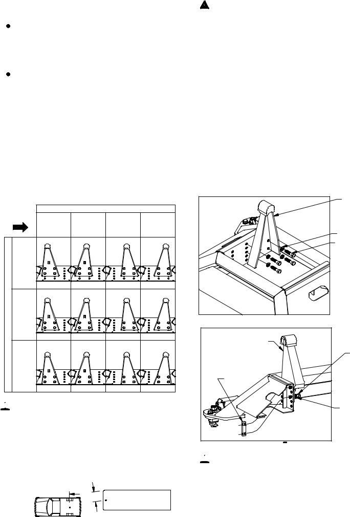
INSTALL PIVOT ARMS |
|||
the sides of the block have threaded holes on one side |
|||
|
|
||
|
|
and smooth bored holes on the other side. When |
|
1. |
Mount the pivot arms using one of the twelve different |
installing the threaded blocks it is critical that the side |
|
with the smooth holes is flat against the bolt plate |
|||
|
locations illustrated in Table A1. These twelve |
||
locations allow flexibility in coupler height (vertical |
when installed. Pass the threaded block under the |
|
bases side and align the block with each set of screws |
||
adjustment) and distance from the cab (horizontal |
||
and start each screw, as shown in Figure A3. After all |
||
adjustment). Choose a location so that your trailer will |
||
the screws are started through the arms, torque each |
||
be as level as possible and have adequate turning |
||
bolt to 80 ft−lbs. |
||
clearance while towing. See warnings below. |
||
|
TABLE A1: Pivot arm position table (driver side)
|
CAB |
|
|
HORIZANTAL ADJUSTMENT |
|
||
|
|
4" BEHIND |
|
|
2" IN FRONT |
||
DIRECTION |
2" |
OVER |
|||||
|
|
|
|
AXLE |
BEHIND |
OF AXLE |
|
|
|
|
|
(FARTHEST |
AXLE |
(CLOSEST |
|
|
|
|
|
AXLE |
|||
|
|
|
|
FROM CAB) |
|
TO CAB) |
|
|
HIGHEST |
POSITIONS |
(19") |
|
|
|
|
VERTICALADJUSTMENT |
MEDIUMHEIGHT |
POSITIONS |
(18") |
|
|
|
|
|
LOWEST |
POSITIONS |
(17") |
|
|
|
|
 WARNING: B&W recommends that you check the clearance between the truck cab and the trailer. Compare the measurement taken from the center of the Coupler to the cab, to the measurement taken from the center of the king pin to the farthest forward corner point of the trailer. These measurements will allow you to see how much clearance you will have between the cab and the trailer while towing and turning.
CENTER OF 
COUPLER TO CAB
 KING PIN TO EDGE OF TRAILER
PIVOT ARM
1/2" LOCKWASHER 1/2" X 2" CAP SCREW
FIGURE A2: Passenger pivot arm mounting location.
PIVOT ARM |
1/2" X 2" |
CAP SCREW |
THREADED |
BLOCK |
1/2" LOCKWASHER |
FIGURE A3: Cutaway view of passenger side bolt plate.

 WARNING: Installing the thread blocks backwards will not allow the pivot arms to be fully tightened in the base and could lead to hitch failure. Before coupling hitch, be sure that none of the 1/2" x 2" bolts are loose and the pivot arms are securely attached to the bolt plate. Failure to check threaded block orientation could cause serious injury or death.
 Loading...