

NautilusTMSCM1
Owner’s Manual
and Warranty
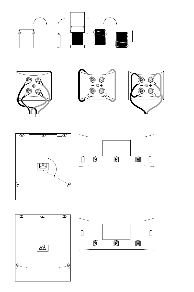
Figure 1
Figure 2
Figure 4a
Figure 5a
Figure 3a
Figure 3b
110° –130°
0.5m –1m
Figure 4b
Figure 5b
>1.5m >0.5m
~
~
~
~
~
~
Figure 6 Figure 7
150mm
16mm
44mm
Figure 8a Figure 8b
Figure 9a Figure 9b

1
Contents
English
Limited Warranty...........2
Owner’s Manual............2
Français
Garantie limitée.............4
Manuel d’utilisation.......4
Deutsch
Beschränkte
Garantie .......................7
Bedienungsanleitung.....7
Español
Garantía limitada.........10
Manual de
instrucciones ..............10
Português
Garantia limitada.........13
Manual do utilizador....13
Italiano
Garanzia limitata .........15
Manuale di istruzioni ...16
Nederlands
Beperkte garantie .......18
Handleiding ................18
Dansk
Begrænset garanti ......21
Brugsanvisning ...........21
Svenska
Begränsad garanti ......23
Bruksanvisning ...........23
Ελληνικά
Περιορισµένη
εγγύηση....................25
Οδηγίες Χρήσεως ....26
Русский
Ограниченная
гарантия....................29
Руководство по
эксплуатации............29
.......................32
.....................32
.......................34
....................34

2
English
Limited Warranty
Dear customer,
Welcome to B&W.
This product has been designed and
manufactured to the highest quality
standards. However, if something does go
wrong with this product, B&W
Loudspeakers and its national distributors
warrant free of charge labour (exclusion
may apply) and replacement parts in any
country served by an official B&W
distributor.
This limited warranty is valid for a period of
five years from the date of purchase or two
years for electronics including amplified
loudspeakers.
Terms and Conditions
1 The warranty is limited to the repair of
the equipment. Neither transportation,
nor any other costs, nor any risk for
removal, transportation and installation
of products is covered by this warranty.
2 This warranty is only valid for the
original owner. It is not transferable.
3 This warranty will not be applicable in
cases other than defects in materials
and/or workmanship at the time of
purchase and will not be applicable:
a for damages caused by incorrect
installation, connection or packing,
b for damages caused by any use other
than correct use described in the user
manual, negligence, modifications, or
use of parts that are not made or
authorised by B&W,
c for damages caused by faulty or
unsuitable ancillary equipment,
d for damages caused by accidents,
lightning, water, fire heat, war, public
disturbances or any other cause
beyond the reasonable control of B&W
and its appointed distributors,
e for products whose serial number has
been altered, deleted, removed or
made illegible,
f if repairs or modifications have been
executed by an unauthorised person.
4 This guarantee complements any
national/regional law obligations of
dealers or national distributors and
does not affect your statutory rights as
a customer.
How to claim repairs under
warranty
Should service be required, please follow
the following procedure:
1 If the equipment is being used in the
country of purchase, you should
contact the B&W authorised dealer
from whom the equipment was
purchased.
2 If the equipment is being used outside
the country of purchase, you should
contact B&W national distributor in the
country of residence who will advise
where the equipment can be serviced.
You can call B&W in the UK or visit our
web site to get the contact details of
your local distributor.
To validate your warranty, you will need to
produce this warranty booklet completed
and stamped by your dealer on the date of
purchase. Alternatively, you will need the
original sales invoice or other proof of
ownership and date of purchase.
Owner’s manual
Introduction
Thank you for choosing B&W.
Your Nautilus™800 Series speakers are
precision transducers incorporating many
innovative techniques unique to B&W and
capable of reproducing recorded sound to
the highest standards. So that they may
perform at their best, it is essential to take
time and care with the installation process.
In particular, you must regard the listening
room as an extension of the speaker. The
acoustic character of the room can have a
profound effect on the final sound quality.
The Nautilus™SCM1 is a shallow speaker
designed for on-wall mounting, primarily for
surround channel use in conjunction with
other Nautilus™800 Series speakers.
However, it may be used wherever a
shallow speaker is required, but bearing in
mind the comments below on magnetic
shielding.
B&W maintains a network of dedicated
distributors in over 60 countries who will
be able to help you should you have any
problems your dealer cannot resolve.
Unpacking (figure 1)
• Fold the carton flaps right back and
invert the carton and contents.
• Lift the carton clear of the contents.
• Remove the inner packing from the
product.
We suggest you retain the packing for
future use.
Check in the carton for:
4 terminal link cables
1 cleaning cloth
2 aluminium wall plates
2 aluminium support plates
8 self adhesive rubber pads
Polythene bag containing:
8 M5 socket screws
2 M8 socket screws
3mm Allen key
6mm Allen key
Warranty booklet
Connections
All connections should be made with the
equipment switched off.
There are 2 pairs of terminals at the back of
the speaker to permit bi-wiring. The lower
pair feed the bass/midrange drive unit and
the upper pair feed the tweeter.
The terminals are insulated to prevent any
likelihood of electrical shock, even when
the speakers are used with the highest
powered amplifiers, and accept a variety of
cable terminations to suit most
applications.
Bi-wiring is the preferred method of
connection and involves the use of
separate cables from the amplifier to each
pair of terminals. The separation of the
signal paths improves the resolution of lowlevel detail and allows the user to optimise
the type of cable to the frequency range of
use. (figure 2)
Should you not want to bi-wire, perhaps
during the initial set-up procedure or
because you do not want to see a
multitude of cables in the room, short
cables are provided to link both positive
and both negative speaker terminals
together. (figure 3)
When using the links, insert the spade into
the slot in the side of one terminal and the
crimped pin into the round side hole in the
other. There is enough clearance to insert a
spade connector from the amplifier into the
same terminal as the crimped pin.
Ensure each positive terminal on the
speaker (coloured red) is connected to the
positive output terminal of the amplifier and
negative (coloured black) to negative.
Incorrect connection can result in poor
imaging and loss of bass.
When bi-wiring, do not use the linking
cables. Take extra care with the polarity of
the connections as incorrect connection
can also impair the frequency response
through the crossover and, if the links are
left in place, may cause damage to the
amplifier by shorting its output terminals.
Positioning
Ascertain the optimum position for the
speaker before fixing the mounting bracket
to the wall.
Stray magnetic fields
The speaker drive units create stray
magnetic fields that extend beyond the
boundaries of the cabinet. We recommend
you keep magnetically sensitive articles
(television and computer screens, computer
discs, audio and video tapes, swipe cards
and the like) at least 0.5m from the
speaker.
For this reason, the Nautilus™SCM1 is only
suitable for use as a centre speaker when
using either projection, plasma or LCD
screens which are not affected by stray
magnetic fields.
Home Theatre
As a surround speaker:
There are two main ways of presenting
surround information. Older movie
soundtracks, where the surround
information was recorded on only one
channel, benefited from a very ambient,
all-enveloping presentation from the
surround speakers, with little attempt to
portray precise imaging to the sides and
rear. More modern 5.1 channel recordings
of both movies and audio have discrete left
and right surround channels, which can

convey more precise imaging. However,
images to the sides and rear are not
generally as precise as can be obtained at
the front. Sustained tones can be more
readily positioned between the speakers
than percussive sounds, which have a
tendency to collapse towards the speakers.
It is also difficult to maintain image position
for all listeners if the listening area is a
significant proportion of the area between
the five speakers. Image stability depends
on getting the right balance between all five
speakers and the ‘hot spot’ effect is even
more marked than for 2-channel audio.
With this in mind, your success in
recreating the producer’s intentions for the
surround field will depend to a great extent
on domestic constraints – how free you are
to position the speakers in an ideal position
and how large an audience you want to
cater for, relative to the size of the room.
There is no industry standard for the angle
subtended by the surround speakers at the
listening position, but most recordings are
made with the surround speakers
positioned between 110° and 130° from
front centre. Place the speakers against the
wall within this range of angles, initially on a
temporary support that raises the tweeters
approximately to ear height. This will define
whether you position the speakers on the
side or rear wall. Point the speakers
towards the centre of the listening area.
(figure 4) The wall bracket will allow the
speaker to be rotated horizontally up to
45°. If you listen in high-backed chairs, or if
the speakers are otherwise obscured, it
may be advantageous to raise them higher.
Satisfactory results can be obtained with
them up to approximately 60cm (2 feet)
above ear height.
With all speakers positioned for initial
listening tests, listen to a wide variety of
programme material – 5.1 channel audio,
action and small scale movies – and sit in
all likely listening positions. Pay particular
attention to the surround information and
the stability of the images.
If the imaging is unsatisfactory, for example
if it becomes too one sided at the extremes
of the listening area, or if you cannot place
the speakers within the preferred range,
you may be better off aiming for a more
diffuse sound field. This can give more
acceptable results in difficult situations. Try
changing the angle of the speakers so they
point away from the listening area. It may
also be advantageous to raise the speakers
well above ear height. (figure 5)
Once you have found the optimum position,
fix the speaker permanently in position (see
below).
As a front centre speaker:
If using a projection television with an
acoustically transparent screen, place the
speaker behind the centre of the screen.
Otherwise position it directly above or
below the screen, whichever is closest to
ear level.
As a front left and right speaker:
Space the speaker between 0.5m (20 in)
and 1m (40 in) from the side of the screen.
If the centre speaker is behind an
acoustically transparent screen, position
the left and right front speaker as nearly as
possible at the same height. If the centre
speaker is above or below the screen, the
height of the left and right speaker should
be between the height of the centre
speaker and the centre of the screen.
Adjust the angle of the speakers to achieve
the most realistic and stable image.
For greatest realism in home theatre
installations it is important to balance the
speakers and adjust the acoustic image to
match the size of the screen. With smaller
screens it may be more realistic to have the
left and right speakers closer together than
you might for audio alone.
Adjust the levels of the three front speakers
to get a smooth transition of sounds as
they pan across the screen. Adjust the level
of the surround speakers so that, except
for special effects, your attention is not
unduly attracted to them.
Sit in all likely listening positions when
deciding on the optimum levels.
Consult your decoder manual for further
information on how to set the levels.
2-Channel Audio
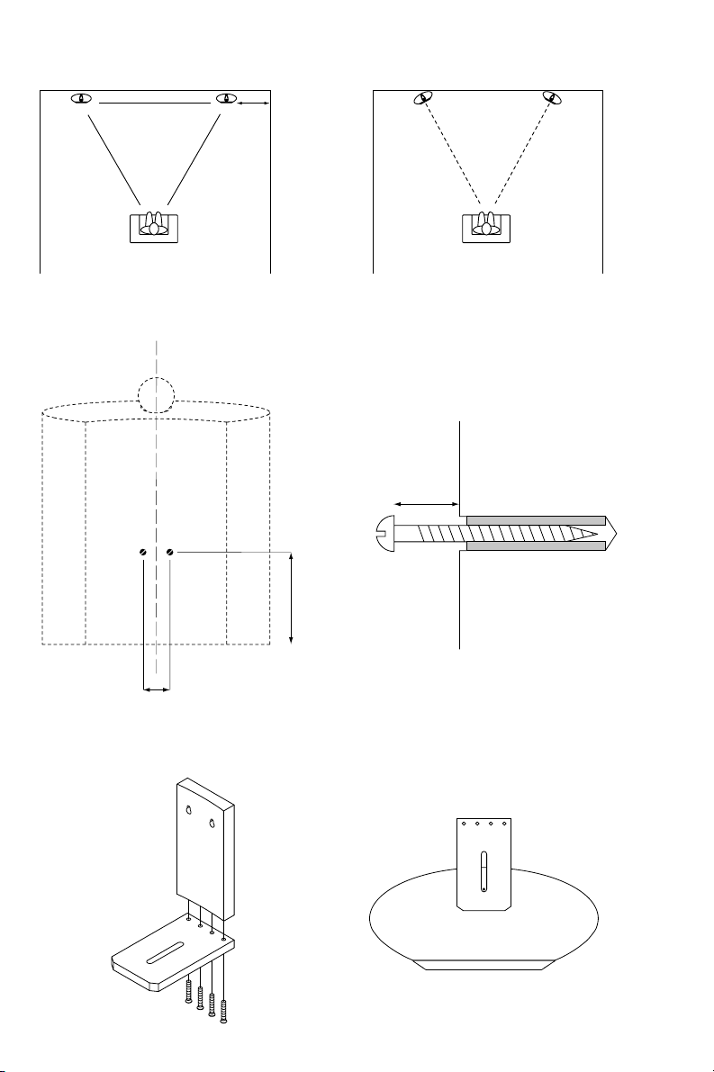
Mount the speakers so that the tweeters
are approximately at ear level.
As an initial guide: (figure 6)
Position the speakers and the centre of the
listening area approximately at the corners
of an equilateral triangle.
Keep the speakers at least 1.5m apart to
maintain left-right separation.
If the central image is poor, try moving the
speakers closer together or toeing them in
so they point at or just in front of the
listeners. (figure 7)
Fine Tuning
Before fine tuning, double check that all the
connections in the installation are correct
and secure.
If the sound is too harsh, increase the
amount of soft furnishing in the room (for
example use heavier curtains), or reduce it
if the sound is dull and lifeless.
Test for flutter echoes by clapping your
hands and listening for rapid repetitions.
Reduce them by the use of irregular
shaped surfaces such as bookshelves and
large pieces of furniture.
For the most discerning listening, remove
the cloth covered grille as described below
in the section ‘Aftercare’. The tweeter is
very delicate and its grille should be left in
position for protection. For this reason the
grille retaining ring is designed to provide
the optimum acoustic environment for the
unit and the response is less smooth with
the grille removed.
Running-in period
The performance of the speaker will change
subtly during the initial listening period. If
the speaker has been stored in a cold
environment, the damping compounds and
suspension materials of the drive units will
take some time to recover their correct
mechanical properties. The drive unit
suspensions will also loosen up during the
first hours of use. The time taken for the
speaker to achieve its intended
performance will vary depending on
previous storage conditions and how it is
used. As a guide, allow up to a week for
the temperature effects to stabilise and
15 hours of average use for the mechanical
parts to attain their intended design
characteristics.
Assembling and fixing the
bracket
Screws and plugs for fitting to the wall are
not supplied. Use round head screws with
a maximum body diameter of 5.0mm
(0.20 in) and a maximum head diameter of
11mm (0.4 in).
Drill and plug two holes in the wall, 150mm
(5.9 in) above where the bottom of the
speaker cabinet will be and horizontally
spaced by 44mm (1.73 in). (figure 8a) Take
special care, especially if fitting into drywall
panels, that the screws and plugs can
support the combined weight of the
speaker and bracket. Insert the screws into
the wall leaving the head 16mm (0.6 in)
clear of the surface. (figure 8b)
Assemble the support plate to the wall
plate using the four M5 screws and the
4mm Allen key. (figure 9a)
Feed the M8 screw through the slot in the
support plate into the threaded insert in the
bottom panel of the enclosure, using the
6mm Allen key. (figure 9b) Initially, position
the screw at the end of the slot furthest
from the wall plate so that the keyhole slots
are clearly visible.
Connect the cables to the speaker and
hook the wall plate over the screws in the
wall.
Adjust the speaker to be as close to the
wall as possible, commensurate with the
angle of rotation.
Should you need to adjust the vertical
angle of the speaker, we recommend you
use an Omnimount 30.0 WB Series wall
bracket in place of the one supplied. It may
be fitted to the additional 4 threaded inserts
in the base of the speaker.
Ancillary equipment
Speakers of this ability deserve signals of
the highest quality. Choose your electronic
equipment and interconnecting cables with
care. We can give guidance on what to
look for when choosing ancillary
equipment, but cannot recommend specific
items. The standards of such products are
improving all the time and your dealer will
be able to demonstrate a variety of suitable
up-to-date products.
In the specification we recommend a range
of amplifier powers. The higher figure is
defined by the power handling capability of
the speaker. When calculating the power
handling, it is assumed that the amplifier is
not run into clipping, which distorts the
frequency power spectrum of the signal,
and that the signal is normal programme
material. Test tones from oscillators and the
like are not applicable. The lower figure is
the minimum we consider necessary to
3

achieve reasonable listening levels without
audible distortion in the smaller room (less
than 50 m3or 1800 cu ft). The higher the
power you use, the less likely you are to
experience amplifier clipping. You can often
tell how good an amplifier is at driving
complex speaker loads by looking at its
power rating into both 4Ω and 8Ω loads.
The nearer the ratio is to 2:1 the better, as
it indicates a good current capability.
In order to reduce the effect the cable has
on the frequency response of the speaker
to inaudible levels, the impedance of the
cable at all frequencies (measuring both
positive and negative conductors in series)
should be kept as low as possible and
certainly below 0.1Ω. At low frequencies,
the DC resistance of the cable is the
dominant factor and you should choose a
gauge of wire sufficient to achieve the
impedance requirements over the length of
cable you need to use. At mid and high
frequencies the inductive component of the
impedance can dominate the DC
resistance. This and other properties
influenced by the detailed construction of
the cable become important. Ask your
dealer for advice on the best cable for your
needs.
Aftercare
The cabinet surface usually only requires
dusting. If you wish to use an aerosol
cleaner, remove the grille first by gently
pulling it away from the cabinet. Spray onto
the cleaning cloth, not directly onto the
cabinet. The grille fabric may be cleaned
with a normal clothes brush whilst the grille
is detached from the cabinet.
Avoid touching the drive unit diaphragms,
especially the tweeter, as damage may
result.
Français
Garantie limitée
Cher Client,
Bienvenue à B&W.
Ce produit a été conçu et fabriqué en vertu
des normes de qualité les plus rigoureuses.
Toutefois, en cas de problème, B&W
Loudspeakers et ses distributeurs
nationaux garantissent une main d’œuvre
(exclusions possibles) et des pièces de
rechange gratuites dans tout pays desservi
par un distributeur agréé de B&W.
Cette garantie limitée est valide pour une
période de cinq ans à compter de la date
d’achat ou une période de deux ans pour
les composants électroniques, y compris
les haut-parleurs amplifiés.
Conditions
1 La garantie est limitée à la réparation
de l’équipement. Les frais de transport
ou autres, les risques associés à
l’enlèvement, au transport et à
l’installation des produits ne sont pas
couverts par cette garantie.
2 La garantie est exclusivement réservée
au propriétaire d’origine et ne peut pas
être transférée.
3 Cette garantie ne s’applique qu’aux
produits faisant l’objet de vices de
matériaux et/ou de construction au
moment de l’achat et ne sera pas
applicable dans les cas suivants :
a détériorations entraînées par une
installation, connexion ou un emballage
incorrect,
b détériorations entraînées par un usage
autre que l’usage correct décrit dans le
manuel de l’utilisateur, la négligence,
des modifications ou l’usage de pièces
qui ne sont pas fabriquées ou agréées
par B&W,
c détériorations entraînées par un
équipement auxiliaire défectueux ou
qui ne convient pas,
d détériorations résultant de : accidents,
foudre, eau, chaleur, guerre, troubles
de l’ordre public ou autre cause ne
relevant pas du contrôle raisonnable de
B&W ou de ses distributeurs agréés,
e les produits dont le numéro de série a
été modifié, effacé, éliminé ou rendu
illisible,
f les produits qui ont été réparés ou
modifiés par une personne non
autorisée.
4 cette garantie vient en complément à
toute obligation juridique nationale /
régionale des revendeurs ou
distributeurs nationaux et n’affecte pas
vos droits statutaires en tant que
client.
Comment faire une réclamation
en vertu de la garantie
Veuillez respecter la procédure ci-dessous,
si vous souhaitez faire une réclamation
sous garantie :
1 Si l’équipement est utilisé dans le pays
d’achat, veuillez contacter le
distributeur agréé de B&W qui a vendu
l’équipement.
2 Si l’équipement est utilisé dans un
pays autre que le pays d’achat, veuillez
contacter le distributeur national B&W
du pays de résidence, qui vous
indiquera où vous pouvez faire réparer
l’équipement. Vous pouvez appeler
B&W au Royaume-Uni ou consulter
notre site Web pour obtenir les
coordonnées de votre distributeur
local.
Afin de valider votre garantie, vous devrez
présenter ce livret de garantie qui aura été
rempli et tamponné par votre revendeur le
jour de l’achat. En l’absence de ce livret,
vous devrez présenter l’original de la
facture commerciale ou une autre preuve
d’achat et de la date d’achat.
Manuel d’utilisation
Introduction
Nous vous remercions d’avoir choisi B&W.
Vos enceintes acoustiques de la série
Nautilus™800 sont des transducteurs de
précision, comprenant de nombreuses
techniques innovantes, uniques à B&W.
Elles sont capables de reproduire vos
enregistrements au niveau de qualité le plus
élevé. Pour obtenir les meilleures
performances, il est essentiel de consacrer
le temps et l’attention nécessaires à leur
installation. En premier lieu, vous ne devez
jamais oublier que la salle d’écoute est une
extension acoustique des enceintes. Le
tempérament acoustique de la salle peut
donc avoir une influence profonde sur la
qualité sonore finale.
La Nautilus™SCM1 est une enceinte peu
profonde, conçue pour être posée contre
un mur. Elle est destinée, à l’origine, à la
reproduction des informations d’ambiances
d’une installation “Surround” équipée
d’autres enceintes de la série
“Nautilus™800”. Elle peut être utilisée,
toutefois, en tant qu’enceinte principale
lorsque la profondeur disponible n’est pas
très importante. Dans ce cas, il suffira de
garder à l’esprit les conseils que nous
formulons plus loin quant à l’émission de
champs magnétiques parasites.
B&W a constitué un réseau de distributeurs
dans plus de 60 pays. Ils sont en mesure
de vous assister au cas où votre revendeur
ne pourrait vous aider.
Deballage (figure 1)
• Repliez complètement les abattants
puis retournez le carton avec son
contenu.
• Soulevez le carton seul.
• Retirez l’emballage intérieur.
Nous vous suggérons de conserver cet
emballage pour une prochaine utilisation.
4

Contrôlez le contenu du carton :
4 câbles de pontage
1 tissu de nettoyage
2 plaques de fixation murale en aluminium
2 plaques support en aluminium
8 tampons auto-adhésifs
Sac en polyéthylène contenant :
8 Vis M5
2 Vis M8
Clé Allen de 3 mm
Clé Allen de 6 mm
Carnet de garantie
Connexions
Toutes les connexions doivent être
effectuées lorsque les appareils
électroniques sont éteints.
Vous trouverez deux paires de bornes
situées au dos de l’enceinte. Elles
autorisent le bicâblage. La paire de bornes
inférieure est raccordée au médium/grave ;
la paire supérieure est raccordée au
tweeter.
Les bornes sont isolées afin d’éviter tout
risque électrique, même si les enceintes
sont utilisées avec des amplificateurs de
forte puissance. Elles acceptent la majorité
des câbles de liaison.
Le bi-câblage est la méthode de connexion
la plus recommandée. Elle nécessite
l’utilisation de câbles séparés reliant
l’amplificateur à chaque paire de bornes.
La séparation totale du trajet emprunté par
le signal pour alimenter les différentes voies
améliore la résolution des micro
informations et permet à l’utilisateur de
choisir le type de câble le mieux adapté à
la gamme de fréquences considérée
(figure 2).
Si vous n’adoptez pas le bi-câblage durant
la procédure de mise en place ou parce
que vous ne désirez pas voir une multitude
de câbles dans votre pièce, nous vous
recommandons de relier les deux bornes
positives entre elles par des fils aussi
courts que possible. Vous procéderez de
même pour les deux bornes négatives
(figure 3).
Lorsque vous utilisez les câbles de pontage
livrés avec les enceintes, insérez la fourche
dans la fente latérale d’une borne et la
cosse sertie dans le trou rond latéral de
l’autre. Il reste assez d’espace libre dans la
borne recevant la pointe sertie, pour insérer
une cosse ouverte, soudée au câble de
liaison à l’amplificateur.
Assurez-vous que chaque borne positive
de l’enceinte (de couleur rouge) est
connectée à la borne positive de
l’amplificateur, de même pour les négatives
(de couleur noire). Une mauvaise connexion
peut entraîner un appauvrissement de
l’image sonore et une perte de grave.
En cas de bi-câblage, n’utilisez pas les
câbles de pontage. Soyez très attentif à la
polarité, une connexion incorrecte peut non
seulement altérer la réponse en fréquence
à travers le filtre de médium/grave, mais
aussi endommager l’amplificateur par
court-circuit, en cas de raccordement
simultané avec les câbles de pontage.
Positionnement
Assurez-vous que l’emplacement de
l’enceinte est optimal, avant de fixer le
support d’installation murale.
Champs magnétiques parasites
Les moteurs de haut-parleurs émettent un
champ magnétique parasite qui rayonne
au-delà des limites de l’enceinte
acoustique. Nous vous recommandons
d’éloigner les appareils sensibles à ce type
de rayonnements (téléviseurs et moniteurs
informatiques, disquettes informatiques,
bandes magnétiques audio ou cassettes
vidéo, cartes à puces etc.) à plus de 0,5 m
du coffret de l’enceinte.
Le Nautilus™SCM1 ne peut être utilisé, en
tant qu’enceinte centrale, qu’avec un
projecteur vidéo, un écran plasma ou LCD,
insensibles aux rayonnements
magnétiques.
Home cinéma
Utilisation comme enceintes
d’ambiances
Il existe deux façons de reproduire les
ambiances. Le son des films anciens, dont
les ambiances et effets ne sont enregistrés
que sur un seul canal, doit être reproduit de
manière indirecte et aussi enveloppante
que possible. Compte tenu du principe de
codage sonore, il ne faudra jamais espérer
obtenir une image précise à l’arrière et sur
les côtés. Les films et enregistrements
sonores plus modernes à 5.1 canaux
comportent des informations
indépendantes sur les canaux d’ambiances
gauche et droit, pouvant produire une
spatialisation plus naturelle ; cependant les
images sonores produites sur les côtés et à
l’arrière restent toujours moins précises que
celles que l’on peut obtenir à l’avant. Les
sons longs et entretenus peuvent être
localisés avec davantage de précision entre
les enceintes que les sons percutants qui
ont tendance à se localiser dans les hauts
parleurs eux-mêmes. Il est également
difficile de maintenir une image sonore
équivalente pour l’ensemble des
spectateurs, si la zone d’écoute représente
une part importante de l’espace situé entre
les cinq enceintes. La stabilité de l’image
sonore résulte de l’obtention d’une balance
convenable entre les cinq enceintes
acoustiques ; la position d’écoute idéale
est donc encore plus précise que dans une
installation stéréophonique à deux canaux.
Ne perdez pas de vue que la reproduction
convaincante et fidèle des intentions du
producteur du film en matière de champ
sonore et d’ambiances dépend, pour une
grande part des contraintes domestiques,
de votre liberté de placer vos enceintes aux
endroits les plus appropriés et de
l’importance de la zone d’écoute que vous
voulez couvrir par rapport aux dimensions
de la pièce.
Il n’existe pas de normes précises
indiquant l’angle formé par les enceintes
d’ambiances et la position d’écoute ;
cependant un très grand nombre
d’enregistrements sont réalisés à partir
d’enceintes “Surround” disposées entre
110° et 130° de part et d’autre de la voie
centrale. Nous vous conseillons d’installer
provisoirement les enceintes d’ambiances,
en respectant cette ouverture, sur un
support temporaire posé contre la paroi, les
tweeters étant placés approximativement à
hauteur d’oreille ; cela vous permettra de
définir si vous choisissez de les installer
définitivement contre les parois latérales ou
le mur arrière. Dirigez-les vers le centre de
la zone d’écoute (figure 4). Le support
mural permettra d’orienter les enceintes par
rotation horizontale jusqu’à 45°. Si vous
écoutez assis dans un fauteuil dont le
dossier est très haut, ou si les haut parleurs
risquent d’être partiellement occultés, il
peut être avantageux de les surélever. Des
résultats satisfaisants peuvent être obtenus
jusqu’à 60 cm au-dessus des oreilles.
Lorsque les enceintes sont en place pour
les premiers tests d’essais, nous vous
recommandons d’écouter une très grande
variété de sujets différents :
enregistrements multicanaux 5.1 – films
d’actions – courts extraits
cinématographiques en essayant chaque
position d’écoute envisageable. Portez une
attention particulière aux informations
d’ambiances et à la stabilité des images
sonores.
Si vous n’êtes pas satisfaits de l’équilibre
de la scène sonore, par exemple si elle a
tendance à se localiser fortement vers un
côté de la zone d’écoute ou si vous ne
pouvez mettre en place les enceintes aux
endroits souhaités, il serait préférable que
vous les disposiez de manière à obtenir un
champ sonore aussi indirect et diffus que
possible ; ce choix procurera de biens
meilleurs résultats dans les situations
délicates. Vous pouvez également essayer
de modifier l’angle des enceintes en le
pointant assez nettement en dehors de la
zone d’écoute ; il peut être également
avantageux de placer les enceintes
largement au-dessus du niveau des oreilles
(figure 5).
Dés que vous aurez déterminé la position
optimale, bloquez définitivement les
enceintes (voir plus loin).
Utilisation comme enceinte centrale
Si vous utilisez un écran de projection
acoustiquement transparent, disposez votre
enceinte derrière lui et bien au centre, sinon
placez-la directement au-dessous ou audessus, la face avant alignée sur l’écran et
toujours au plus près de la hauteur des
oreilles.
Utilisation comme enceinte centrale
gauche et droite
Eloignez l’enceinte de 0,5 à 1 mètre du
bord de l’écran.
Si l’enceinte centrale se trouve au-dessus
ou en-dessous de l’écran, la hauteur des
enceintes gauche et droite sera choisie à
mi-distance entre la hauteur de l’enceinte
centrale et le centre de l’écran. Ajustez
l’angle formé par les enceintes pour obtenir
l’image sonore la plus réaliste et la plus
stable.
Pour améliorer le réalisme d’une installation
de « home cinéma », il est essentiel de
parvenir à une harmonie naturelle entre la
taille de l’image sonore procurée par les
enceintes et la taille de l’écran. Lorsque ce
dernier est de dimensions réduites, le
résultat est plus convaincant lorsque les
5

enceintes sont moins écartées que pour
l’écoute musicale en stéréophonie
habituelle.
Réglez le niveau des trois enceintes
frontales de manière à obtenir une
transition progressive et régulière des sons
prévus pour se déplacer de façon
panoramique, d’une extrémité à l’autre.
Réglez le niveau des enceintes
d’ambiances pour que, sauf cas d’effets
spéciaux, votre attention ne puisse être
attirée par elles.
Essayez toutes les places d’écoute
préférentielles avant de décider des
réglages définitifs.
Consultez le mode d’emploi de votre
décodeur ; il vous expliquera comment
procéder aux différents réglages de
niveaux.
Stéréophonie à deux canaux
Installez les enceintes de façon à placer les
tweeters approximativement à hauteur
d’oreilles.
Conseils préliminaires (figure 6) :
Disposez les enceintes acoustiques ainsi
que le centre de la zone d’écoute
approximativement aux trois angles d’un
triangle équilatéral.
Ecartez vos enceintes d’au moins 1,5 m
pour obtenir une séparation gauche/droite
suffisante.
Si l’image centrale est vraiment pauvre,
rapprochez les deux enceintes l’une de
l’autre ou orientez-les vers un point situé
juste en avant de l’auditeur (figure 7).
Réglages fins
Avant de procéder aux réglages fins,
vérifiez que toutes les connexions de
l’installation sont correctes et bien serrées.
Si le son est trop agressif, augmentez la
quantité de matériaux absorbants dans la
pièce (par exemple, utilisez des rideaux
plus épais), ou réduisez-la si le son est
sourd et sans vie.
Vérifiez la présence d’échos brefs (flutter
echo) en tapant dans vos mains et écoutez
s’il se produit de très rapides et très courts
échos. Réduisez-le en utilisant des surfaces
irrégulières et accidentées comme une
bibliothèque ou de grands rideaux.
Pour obtenir une restitution plus
transparente et précise, nous vous
recommandons de retirer les grilles de
protection du haut-parleur de grave et du
médium (veuillez vous reporter à la rubrique
« précautions »). Le tweeter étant très
délicat, sa grille ne doit jamais être retirée.
Pour cette raison, l’anneau de fixation de la
grille a été spécialement étudié pour une
reproduction optimale de l’aigu. La
reproduction serait moins agréable en
l’absence de grille.
Rodage
Les performances de vos enceintes vont
s’améliorer durant les premières heures
d’écoute. Le temps nécessaire pour que
vos enceintes puissent atteindre leur
rendement optimal dépendra de leurs
conditions d’entreposage et de leur
utilisation. Par exemple, lorsqu’elles ont été
entreposées dans un endroit froid, leurs
composants d’amortissement ainsi que les
suspensions des haut-parleurs ne
retrouvent leurs caractéristiques
mécaniques initiales qu’après une plus ou
moins longue période de fonctionnement.
A titre indicatif, il faut prévoir une semaine
d’acclimatation à température ambiante
dans vos locaux et 15 heures d’usage
moyen pour que les parties mécaniques
atteignent les caractéristiques prévues.
Assemblage et fixation du
support
Les vis murales ne sont pas fournies.
Utilisez des vis à tête ronde de 5 mm
maximum et dont le diamètre de tête
n’excède pas 11 mm.
Percez deux trous, écartés de 44 mm dans
le plan horizontal, à une hauteur égale à
150 mm au-dessus de l’endroit du mur où
se situera la base de l’enceinte et enfoncez
eux chevilles de format bien adapté (figure
8a). Prenez garde, en particulier si vous
percez une cloison en plâtre, que les vis et
les chevilles supportent le poids combiné
de l’enceinte et du support. Serrez les vis
dans le mur en prenant soin de laisser un
espace entre la cloison et la tête de 16 mm
(figure 8b).
Assemblez la plaque support et la plaque
murale en utilisant les vis M5 et la clé Allen
de 4 mm (figure 9a).
Faites passer la vis M8 à travers la fente du
plateau support et vissez la dans l’insert
taraudé situé au dos de l’enceinte en
utilisant la clé Allen de 6 mm (figure 9b).
Placez la vis au bout de la fente, opposé à
la plaque murale. Les trous de serrure
doivent rester clairement visibles.
Raccordez les câbles, avant d’accrocher la
plaque murale sur les vis de la cloison.
Placez l’enceinte pour qu’elle se trouve au
plus près du mur en tenant compte de
l’angle de rotation.
Si vous devez orienter l’enceinte sur le plan
vertical, nous recommandons de remplacer
le support mural fourni par un Omnimount
30.0 WB. Ce modèle s’adapte sans
problème aux 4 inserts encastrés dans la
base de l’enceinte.
Accessoires
Les grandes possibilités de restitution
offertes par ces enceintes demandent un
soin particulier dans le choix des
électroniques et des câbles de liaison.
Nous pouvons guider votre choix mais il
nous est impossible de vous recommander
un produit en particulier. Les
caractéristiques de ces matériels évoluant
en permanence; votre revendeur saura
vous proposer un ensemble d’éléments
actualisés.
Dans nos spécifications techniques nous
indiquons une marge de puissance pour les
amplificateurs. La valeur la plus élevée
correspond à la puissance continue
maximale pouvant être supportée par
l’enceinte. Pour déterminer la puissance
utile, il faut s’assurer que l’amplificateur ne
saturera jamais ; la saturation déforme le
signal sonore et est très dangereuse pour
les haut-parleurs. Une enceinte acoustique
est prévue pour diffuser des programmes
musicaux normaux ; les signaux tests
provenant de générateurs ou similaires
doivent être proscrits. L’indication de
puissance la plus faible correspond à ce
que nous considérons comme nécessaire
pour parvenir à un niveau sonore
raisonnable, sans distorsions audibles,
dans une pièce de dimensions modestes
(moins de 50 m3). Plus la puissance de
votre amplificateur est élevée, plus vous
limitez les risques de saturation. Compte
tenu du fait qu’une enceinte acoustique
représente une charge complexe, nous
vous recommandons de choisir un très bon
amplificateur. Comme première approche,
vous devez rechercher un appareil dont la
puissance efficace sous 4 ohms représente
pratiquement deux fois la puissance
obtenue sous 8 ohms. Cette précaution
garantit une excellente capacité en courant.
Dans le but de réduire à un niveau
inaudible l’influence que les câbles peuvent
avoir sur la réponse en fréquences de vos
enceintes, l’impédance de ceux-ci,
mesurée à toutes les fréquences et les
deux conducteurs en série, doit être aussi
faible que possible et toujours inférieure à
0,1 ohm. Aux basses fréquences, la
résistance en courant continu est le facteur
dominant ; vous choisirez une section de
câble permettant d’atteindre l’impédance
requise en fonction de la longueur que vous
souhaitez utiliser. Aux fréquences
moyennes et élevées, la composante
inductive de l’impédance peut dominer la
résistance en courant continu. Ces
caractéristiques et d’autres dépendent de
la conception du câble. Demandez à votre
revendeur de vous indiquer le modèle
convenant le mieux à votre application.
Precautions
Pour l’entretien de l’ébénisterie vous
procéderez usuellement à un simple
dépoussiérage. Au cas où vous utiliseriez
un nettoyant en aérosol, retirez d’abord les
grilles en tissu, vaporisez le produit
directement sur le chiffon, jamais sur
l’enceinte. Le tissu peut être nettoyé au
moyen d’une brosse, après que vous ayez
retiré la grille de l’enceinte.
Evitez de toucher les membranes des hautparleurs et spécialement celle du tweeter
pour ne pas les détériorer.
6

Deutsch
Garantie
Sehr geehrte Kundin, sehr geehrter Kunde,
willkommen bei B&W.
Dieses Produkt wurde nach den höchsten
Qualitätsstandards entwickelt und
hergestellt. Sollte dennoch der
unwahrscheinliche Fall eintreten, dass Sie
als Kunde Grund zur Reklamation haben,
werden B&W Loudspeakers und seine
nationalen Vertriebsgesellschaften das
fehlerhafte Produkt ohne Berechnung der
Arbeits- und Materialkosten (abgesehen
von einigen Ausnahmen) in jedem Land, in
dem eine offizielle B&WVertriebsgesellschaft vertreten ist,
reparieren.
Die Garantiezeit beträgt fünf Jahre ab
Kaufdatum bzw. zwei Jahre auf
Aktivlautsprecher und elektronische
Bauteile.
Garantiebedingungen
1 Die Garantie ist auf die Reparatur der
Geräte beschränkt. Weder der
Transport noch sonstige Kosten, noch
das Risiko des Ausbaus, des
Transports und der Installation der
Produkte wird von dieser Garantie
abgedeckt.
2 Diese Garantie gilt nur für den
Originalbesitzer. Sie ist nicht
übertragbar.
3 Diese Garantie ist nur dann gültig,
wenn zum Zeitpunkt des Kaufs
Fabrikations- und/oder Materialfehler
vorliegen und nicht:
a bei Schäden durch unfachmännische
Installation, falsches Anschließen oder
unsachgemäßes Verpacken,
b bei Schäden, die auf einen nicht in der
Bedienungsanleitung genannten
Einsatzzweck, auf Fahrlässigkeit,
Modifikationen oder die Verwendung
von Teilen zurückzuführen sind, die
nicht von B&W hergestellt bzw.
zugelassen wurden,
c bei Schäden durch defekte oder
ungeeignete Zusatzgeräte,
d bei Schäden durch Unfälle, Blitzschlag,
Wasser, Feuer, Hitze, Krieg, öffentliche
Unruhen oder sonstige Ereignisse, die
nicht der Kontrolle von B&W und
seinen Vertriebsgesellschaften
unterliegen,
e für Produkte, deren Seriennummern
geändert, gelöscht, entfernt oder
unleserlich gemacht wurden,
f wenn Reparaturen oder Modifikationen
von einem Nichtfachmann durchgeführt
wurden.
4 Diese Garantie ergänzt die
nationalen/regionalen gesetzlichen
Verpflichtungen der Händler bzw. der
nationalen Vertriebsgesellschaften und
schränkt in keiner Weise die
gesetzlichen Rechte, die Sie als Kunde
haben, ein.
Inanspruchnahme von
Garantieleistungen
Sollten Sie unseren Service in Anspruch
nehmen müssen, gehen Sie bitte
folgendermaßen vor:
1 Befindet sich das Gerät in dem Land,
in dem Sie es gekauft haben, setzen
Sie sich mit Ihrem autorisierten B&WFachhändler in Verbindung.
2 Befindet sich das Gerät außerhalb des
Landes, in dem Sie es gekauft haben,
wenden Sie sich bitte an die nationale
B&W-Vertriebsgesellschaft des Landes,
in dem Sie leben. Diese wird Ihnen
Auskunft darüber geben, wo Sie das
Gerät reparieren lassen können. Die
Adresse der für das jeweilige Land
zuständigen Vertriebsgesellschaft
erhalten Sie bei B&W in Großbritannien
oder über unsere Website.
Garantieleistungen werden nur erbracht,
wenn dieses Garantie-Booklet (vollständig
ausgefüllt und mit dem Händlerstempel und
dem Kaufdatum versehen) vorgelegt wird.
Ist dies nicht möglich, ist als Kaufbeleg die
Originalrechnung oder ein anderer
Kaufbeleg vorzulegen, aus dem auch das
Kaufdatum ersichtlich wird und der Sie als
Eigentümer des Gerätes ausweist.
Bedienungsanleitung
Einleitung
Vielen Dank, daß Sie sich für ein Produkt
der Marke B&W entschieden haben.
Mit den Lautsprechern der Nautilus™800Serie haben Sie Präzisions-Schallwandler
erworben, in die viele innovative
Technologien eingeflossen sind, die B&W
so einzigartig machen. Dank dieser
Technologien ist es möglich, höchste
Wiedergabequalität zu gewährleisten. Zur
Klangoptimierung ist es erforderlich, sich
für das Aufstellen Zeit zu nehmen.
Beachten Sie, daß der akustische
Charakter des Hörraumes einen
erheblichen Effekt auf die Klangqualität hat.
Die Nautilus™SCM1 ist ein flacher
Wandlautsprecher, der in Kombination mit
anderen Lautsprechern der Nautilus™800Serie vorwiegend für den Einsatz als
Surroundlautsprecher entwickelt wurde. Er
kann aber auch überall dort genutzt
werden, wo der Einsatz eines flachen
Lautsprechers Sinn macht. Lesen Sie sich
aber vorher bitte die Hinweise zur
magnetischen Abschirmung in dieser
Anleitung durch (siehe unten).
B&W unterhält in mehr als 60 Ländern ein
Netz erfahrener Distributoren, die Ihnen
zusammen mit dem autorisierten
Fachhändler jederzeit weiterhelfen, um
Ihnen den Musikgenuß zu Hause zu
ermöglichen.
Auspacken (Abbildung 1)
• Klappen Sie die Laschen des Kartons
nach hinten und drehen Sie Karton
samt Inhalt um.
• Heben Sie den Karton vom Inhalt ab.
• Entfernen Sie die Innenverpackung
vom Lautsprecher.
Wir empfehlen, die Verpackung für einen
eventuellen späteren Transport
aufzubewahren.
Im Versandkarton sind enthalten:
4 Verbindungskabel für die
Anschlußklemmen
1 Reinigungstuch
2 Wandplatten aus Aluminium
2 Trägerplatten aus Aluminium
8 selbstklebende Gummifüße
Der PE-Beutel enthält:
8 M5-Schrauben
2 M8-Schrauben
3-mm-Innensechskantschlüssel
6-mm-Innensechskantschlüssel
Warranty booklet (Hinweise zur Garantie)
Anschließen der lautsprecher
Während des Anschließens sollten alle
Geräte abgeschaltet sein.
Auf der Rückseite des Lautsprechers
befinden sich zwei Paar Anschlußklemmen
für Bi-Wiring-Anwendungen, das untere
Paar zur Signalübertragung zum Tief/Mitteltöner, das obere Paar zur
Signalübertragung zum Hochtöner.
Um auch beim Betrieb mit extrem
leistungsstarken Verstärkern der Gefahr
eines elektrischen Schlags vorzubeugen,
sind die Anschlußklemmen isoliert. Für den
Anschluß an den Verstärker ist eine große
Auswahl an Verbindungskabeln erhältlich,
und somit sind die meisten Anwendungen
möglich.
Bi-Wiring ist die bevorzugte
Anschlußmethode und setzt die
Verwendung verschiedener Kabel vom
Verstärker zu jedem Anschlußklemmenpaar
voraus. Die Trennung der Signalwege
erhöht die Auflösung bei tiefen Frequenzen
und ermöglicht es dem Anwender, das für
das jeweilige Frequenzspektrum beste
Kabel einzusetzen (Abbildung 2).
Möchten Sie während der
Systemeinstellung oder aufgrund der
höheren Anzahl an Anschlußkabeln auf BiWiring verzichten, nutzen Sie die zum
Lieferumfang gehörenden kurzen
Verbindungskabel und verbinden damit die
positiven und negativen Lautsprecheranschlußklemmen miteinander
(Abbildung 3).
Zum Anschluß der Verbindungskabel führen
Sie den Kabelschuh in den Schlitz an der
Seite der einen Anschlußklemme ein und
stecken das andere Ende des
Verbindungskabels mit dem gecrimpten Pin
in das seitliche Loch der anderen Anschlußklemme (Abbildung 3a). An dieser
Anschlußklemme findet sich noch
genügend Spielraum für ein mit einem
Kabelschuh versehenes Lautsprecherkabel
vom Verstärker (Abbildung 3b).
Verbinden Sie mit den Verbindungskabeln
nur jeweils gleichpolig bezeichnete
Anschlußklemmen. Achten Sie auf festen
Sitz der Anschlußkabel an den
7

Anschlußklemmen. Überprüfen Sie
gegebenenfalls von Zeit zu Zeit deren Sitz.
Schließen Sie die (rot markierten) positiven
Anschlußklemmen an den positiven
Ausgang des Verstärkers und die (schwarz
markierten) negativen Anschlußklemmen an
den negativen Ausgang des Verstärkers an.
Verwenden Sie die kurzen
Verbindungskabel nie in Bi-WiringAnwendungen. Achten Sie hierbei
besonders genau auf die richtige Polarität,
da bei falschem Anschluß der
Frequenzgang über die Tief-MitteltonWeiche beeinträchtigt werden kann. Ferner
kann es, falls die kurzen Verbindungskabel
nicht entfernt worden sind, durch
Kurzschließen der Ausgangsanschlüsse zu
einer Beschädigung des Verstärkers
kommen.
Positionierung
Befestigen Sie die Wandhalterung erst,
wenn Sie die optimale Position für Ihre
Lautsprecher gefunden haben.
Magnetische Streufelder
Die Lautsprecherchassis erzeugen ein
magnetisches Streufeld. Daher empfehlen
wir, einen Mindestabstand von 0,5 m
zwischen magnetisch empfindlichen
Artikeln (Disketten, Chequekarten,
mechanischen Armbanduhren, Audio- und
Videobändern usw.) und Lautsprecher zu
bewahren.
Aus diesem Grund sollte die SCM1 nur in
Kombination mit akustisch transparenten
Leinwänden, Plasma- oder LCDBildschirmen als Centerlautsprecher
eingesetzt werden.
HiFi-Cinema
Einsatz als Surroundlautsprecher
Es gibt zwei Arten, Surroundinformationen
zu präsentieren. Ältere Film-Soundtracks,
bei denen die Surroundinformationen auf
einem Kanal aufgenommen wurden,
profitieren von intensiven Raumeffekten aus
den Surroundlautsprechern. Heutige 5.1Kanal-Aufnahmen (Film und Musik) haben
links und rechts diskrete Surroundkanäle,
die ein präziseres Klangbild übertragen.
Jedoch ist das Klangbild zu den Seiten und
nach hinten im allgemeinen nicht so präzise
wie vorne. Phantomklangbilder zwischen
den Lautsprechern sind mit Dauertönen
einfach zu erzeugen, Reiblaute haben
dagegen die Eigenschaft, den Ton an den
Lautsprechern zu lokalisieren. Schwierig ist
es, für mehr als eine Zuhörerreihe ein
ideales Gleichgewicht zwischen Front- und
Surroundlautsprechern herzustellen.
Grundsätzlich gelangt von jedem
Lautsprecher ein Teil des Schalls direkt zum
Ohr, ein anderer wird zuvor an den
Zimmerwänden reflektiert. Gute
Surroundeffekte zeichnen sich durch ein
gutes Verhältnis von direktem zu
reflektiertem Schallanteil am Hörplatz aus.
Zu viele reflektierte Anteile verwässern die
Effekte, ein zu hoher Anteil an direktem
Schall wirkt sich negativ auf den Realismus
von Umgebungseffekten aus. Es kommt auf
die richtige Mischung an. Diese hängt aber
stark von der Raumakustik, den
Möglichkeiten, die Sie bei der
Positionierung der Lautsprecher haben und
der Anzahl der Zuhörer ab.
Es gibt keinen Industriestandard für den
Winkel, den ein Surroundlautsprecher
gegenüber der Hörposition haben sollte.
Bei den meisten Aufnahmen werden die
Surroundlautsprecher allerdings in einem
Winkel von 110° bis 130° zum
Frontzentrum ausgerichtet. Plazieren Sie
die Lautsprecher vorübergehend in diesem
Winkelbereich an der Wand. Die Hochtöner
sollten sich dabei in Ohrhöhe befinden. Auf
diese Weise finden Sie heraus, ob Sie die
Lautsprecher besser seitlich oder an der
Rückwand plazieren. Richten Sie die
Lautsprecher dem Mittelpunkt des
Hörbereichs entsprechend aus
(Abbildung 4). Die Wandhalterung
ermöglicht horizontal eine Drehung um 45°.
Sitzen Sie z.B. in einem Sessel mit hoher
Rückenlehne, kann es vorteilhaft sein, die
Lautsprecher höher anzubringen.
Zufriedenstellende Ergebnisse werden bis
zu einem Abstand von ca. 60 cm über
Ohrhöhe erzielt.
Sind alle Lautsprecher für einen ersten
Hörtest in ihrer Position, hören Sie sich eine
möglichst große Bandbreite an Quellen an –
5.1-Kanal-Audio, Action-Filme usw.
Verändern Sie Ihre Hörposition mehrmals.
Achten Sie besonders auf die
Surroundinformationen und die Stabilität
der Klangbilder.
Sollte das Klangbild nicht zufriedenstellend
ausfallen oder können Sie die Lautsprecher
nicht im bevorzugten Bereich anbringen,
sollten Sie ein möglichst diffuses Klangbild
anstreben. Dies kann auch unter
schwierigen Bedingungen zu Ergebnissen
führen, die akzeptabel sind. Versuchen Sie,
den Winkel der Lautsprecher dahingehend
zu verändern, daß sie nicht mehr in den
Hörbereich zeigen. Darüber hinaus kann es
vorteilhaft sein, die Lautsprecher in einigem
Abstand oberhalb der Ohrhöhe zu plazieren
(Abbildung 5).
Haben Sie die optimale Position gefunden,
befestigen Sie die Lautsprecher dauerhaft
(siehe unten).
Einsatz als Centerlautsprecher
Bei Einsatz eines Projektors plazieren Sie
den Lautsprecher mittig hinter der
akustisch transparenten Leinwand.
Ansonsten ist der Lautsprecher direkt auf
bzw. unter dem Bildschirm zu positionieren
und zwar so, daß er sich möglichst in
Ohrhöhe befindet.
Einsatz als linker und rechter
Frontlautsprecher
Positionieren Sie die Lautsprecher seitlich
vom Bildschirm mit einem Abstand von 0,5
bis 1,0 m.
Befindet sich der Lautsprecher hinter einer
akustisch transparenten Leinwand,
plazieren Sie den linken und rechten
Lautsprecher möglichst auf gleicher Höhe.
Befindet sich der Centerlautsprecher auf
bzw. unter dem Bildschirm, sollte die Höhe
des linken und rechten Lautsprechers
zwischen der Höhe des
Centerlautsprechers und der
Bildschirmmitte liegen. Richten Sie die
Lautsprecher so aus, daß ein möglichst
realistisches und stabiles Klangbild erzeugt
wird.
Zur Gewährleistung einer größtmöglichen
Realitätsnähe in einem Home-HiFi-CinemaSystem ist es wichtig, die Lautsprecher gut
auszurichten und das Klangbild auf die
Bildschirmgröße abzustimmen. Bei
kleineren Bildschirmen sollten linker und
rechter Lautsprecher näher
zusammengestellt werden als es in reinen
Audio-Anwendungen üblich ist.
Stimmen Sie die Schallpegel vom linken,
rechten und Center-Lautsprecher bei
laufendem Film aufeinander ab. Der Pegel
der Surround-Lautsprecher sollte so sein,
daß die Aufmerksamkeit des Zuhörers (mit
Ausnahme von Spezialeffekten) nicht auf sie
gerichtet wird.
Setzen Sie sich an alle möglichen
Hörpositionen, um ein optimales Einpegeln
zu gewährleisten.
Ihrem Decoder-Handbuch können Sie
detaillierte Informationen zum Einpegeln
entnehmen.
2-Kanal-Audio
Bringen Sie die Lautsprecher so an, daß
sich die Hochtöner ungefähr in Ohrhöhe
befinden.
Grundsätzlich gilt (Abbildung 6):
Die Lautsprecher und der Hörbereich
sollten ein gleichseitiges Dreieck bilden.
Der Abstand zwischen den Lautsprechern
sollte zur Gewährleistung einer exakten
Stereokanaltrennung mindestens 1,5 m
betragen.
Ist der Abstand zwischen den
Lautsprechern zu groß, kann es zu
klanglichen Einbußen im mittleren Bereich
des Hörraumes kommen. Versuchen Sie,
den Abstand zwischen den Lautsprechern
zu verringern oder auf die Hörposition
auszurichten (Abbildung 7).
Feinabstimmung
Prüfen Sie vor der Feinabstimmung Ihres
Systems noch einmal, ob alle Verbindungen
richtig hergestellt wurden.
Ist der Klang eher zu hell, hilft die
Verwendung weicher
Einrichtungsgegenstände wie z.B. schwerer
Vorhänge. Umgekehrt sollte man bei
dumpfem, leblosem Klang die Verwendung
solcher Einrichtungsgegenstände auf ein
Minimum reduzieren.
Prüfen Sie den Raum auf Mehrfachechos.
Klatschen Sie in die Hände und hören Sie,
ob Echos auftreten. Diesen Echos kann
durch die Verwendung unregelmäßiger
Oberflächen wie z.B. Regalen oder großen
Möbelstücken entgegengewirkt werden.
Bei Hörtests sollten Sie die mit Stoff
bespannte Lautsprecherabdeckung wie
unten in Abschnitt „PFLEGE“ beschrieben
entfernen. Der Hochtöner ist sehr
empfindlich. Daher sollte seine Abdeckung
nicht entfernt werden. Der Ring um die
Abdeckung ist so ausgelegt, daß er eine
8

optimale akustische Umgebung für den
Hochtöner darstellt und die Wiedergabequalität ohne Abdeckung schlechter ist.
Einlaufphase
In der Einlaufphase gibt es feine
Unterschiede in der Wiedergabequalität des
Lautsprechers. Wurde der Lautsprecher in
einer kühlen Umgebung gelagert, so wird
es einige Zeit dauern, bis die
Dämpfungskomponenten und die für die
Aufhängung der Chassis eingesetzten
Werkstoffe ihre optimalen mechanischen
Eigenschaften besitzen. Die Aufhängung
der Chassis wird mit den ersten
Betriebsstunden beweglicher. Die Zeit, die
der Lautsprecher benötigt, um seine
maximale Leistungsfähigkeit zu entwickeln,
schwankt abhängig von den vorherigen
Lager- und den Einsatzbedingungen.
Grundsätzlich kann man sagen, daß es eine
Woche dauert, bis sich die Lautsprecher
nach Temperatureinwirkungen stabilisiert
haben. 15 Betriebsstunden sind
erforderlich, bis die mechanischen Teile ihre
Funktion wie bei der Konstruktion
festgelegt erfüllen können.
Anbringen und Befestigen der
Wandhalterung
Die Schrauben und Dübel zur Befestigung
der Wandhalterung sind im Lieferumfang
nicht enthalten. Verwenden Sie Schrauben
mit einem Gewindedurchmesser von
5,0 mm und einem maximalen
Kopfdurchmesser von 11 mm.
Bohren Sie in einem Abstand von 150 mm
zum Lautsprecherboden und horizontal in
einem Abstand von 44 mm zwei Löcher in
die Wand (Abbildung 8a). Stellen Sie
unbedingt sicher, daß die Schrauben und
Dübel stabil genug sind, um das Gewicht
von Lautsprecher und Halterung zu tragen.
Drehen Sie die Schrauben ein, bis der
Abstand zwischen Schraubenkopf und
Wand 16 mm beträgt (Abbildung 8b).
Schrauben Sie die Trägerplatte mit vier
M5-Schrauben an die Wandplatte.
Verwenden Sie dazu den beiliegenden
4-mm-Innensechskantschlüssel
(Abildung 9a).
Führen Sie die M8-Schraube mit dem
6-mm-Innensechskantschlüssel durch die
Öffnung an der Trägerplatte in die Bohrung
am Boden des Lautsprechergehäuses
(Abbildung 9b). Positionieren Sie die
Schraube so, daß die Langlöcher sichtbar
bleiben.
Schließen Sie die Kabel an die
Lautsprecher an und hängen Sie die
Wandplatte über den Schrauben an die
Wand.
Die Lautsprecher sollten im Einklang mit
dem Rotationswinkel möglichst wandnah
plaziert werden.
Möchten Sie den Lautsprecher vertikal
ausrichten, empfehlen wir, anstelle der
beiliegenden Halterung eine Wandhalterung
der Serie Omnimount 30.0 WB zu
verwenden. Befestigen Sie diese an den
vier zusätzlichen Bohrungen im
Lautsprecherboden.
Zusätzliches Equipment
Derart wertige Lautsprecher erzeugen
Signale höchster Klangtreue. Wählen Sie
die Elektronik und die Verbindungskabel
sorgfältig aus. Wir können Ihnen
Ratschläge geben, worauf Sie bei der
Auswahl des Equipments achten sollten,
jedoch können wir keine speziellen
Komponenten nennen. Die Qualität dieser
Komponenten wird ständig besser und Ihr
autorisierter B&W-Fachhändler kann Ihnen
eine Reihe kombinierbarer Geräte
vorführen, die dem neuesten Stand der
Technik entsprechen.
In den technischen Daten finden Sie eine
Bereichsangabe zur Belastbarkeit. Die
höhere Angabe ergibt sich aus der reinen
Belastbarkeit des Lautsprechers. Sie wurde
unter der Voraussetzung ermittelt, daß der
Verstärker in einem verzerrungsfreien
Betriebzustand arbeitet und normale
Musiksignale wiedergegeben werden sollen.
Oszillator-Testsignale und ähnlich
ohrenbetäubende Testtöne sind keine
Musik! Die kleinere Leistungsangabe stellt
das Minimum an Verstärkerleistung dar, das
wir für nötig erachten, um normale
Abhörlautstärken in einem kleineren Raum
(unter 20 qm) ohne hörbare
Klangbeeinträchtigung zu erreichen. Je
höher die Leistung des verwendeten
Verstärkers ist, desto geringer wird die
Gefahr, den Verstärker in dem für die
Lautsprecher gefährlichen verzerrenden
Betriebszustand (Clipping) zu betreiben.
Wie gut ein Verstärker mit der komplexen
Belastung durch einen Lautsprecher
zurechtkommt, kann man anhand der
Leistungsangaben an 4-Ohm- und 8-OhmLasten beurteilen: Nähern sich diese beiden
Angaben einem Verhältnis von 2 : 1 an, ist
dies ein Zeichen für eine gute Stromlieferfähigkeit des Verstärkers.
Mit dem Ziel, Effekte des
Lautsprecherkabels auf die
Musikwiedergabe des Lautsprechers auf ein
unhörbares Niveau zu reduzieren, sollte der
Widerstand des Kabels über den gesamten
Frequenzbereich (positver und negativer
Leitungsweg in „Reihe“ gemessen) so
gering wie möglich, mindestens aber unter
0,1 Ohm gehalten werden.
Haupteinflußfaktor bei tiefen Frequenzen ist
der Gleichstromwiderstand des Kabels. Um
die Impedanzwerte nicht zu überschreiten,
sollten Sie den Kabelquerschnitt in
Abhängigkeit zu den verwendeten
Kabellängen wählen. Bei mittleren und
hohen Frequenzen können die induktiven
Bestandteile des Widerstandes den
Gleichstromwiderstand in Ihrer Auswirkung
übertreffen. Diese und andere Eigenschaften
hängen stark von der Konstruktion eines
Kabels ab. Fragen Sie Ihren autorisierten
B&W-Fachhändler und lassen Sie sich für
Ihren Einsatzzweck optimal beraten.
Pflege
Die Gehäuseoberfläche muß in der Regel
nur abgestaubt werden. Bei Verwendung
eines Aerosol-Reinigers entfernen Sie vor
dem Reinigen zunächst vorsichtig die
Abdeckung vom Gehäuse. Sprühen Sie den
Reiniger auf ein Tuch, niemals direkt auf
das Gehäuse. Der Stoff kann nach dem
Entfernen der Abdeckung mit einer
normalen Kleiderbürste gereinigt werden.
Vermeiden Sie es, die Lautsprecherchassis
zu berühren, da dies zu Beschädigungen
führen kann. Das gilt vor allem für den
Hochtöner.
9

Español
Garantía limitada
Estimado cliente:
Bienvenido a B&W.
Este producto ha sido diseñado y fabricado
de acuerdo con las más altas normas de
calidad. Sin embargo, si hallara algún
desperfecto en el mismo, B&W
Loudspeakers y sus distribuidores
nacionales garantizan, sin coste alguno
para usted, la mano de obra (es posible
que haya excepciones) y la reposición de
piezas en cualquier país donde se cuente
con un distribuidor autorizado de B&W.
Esta garantía limitada es válida por un
período de cinco años desde la fecha de
compra (dos años para las partes
electrónicas) incluyendo altavoces
amplificados.
Términos y condiciones
1 Esta garantía está limitada a la
reparación del equipo. La garantía no
cubre ni el transporte ni otros costes;
tampoco cubre ningún riesgo por
traslado, transporte e instalación de los
productos.
2 La garantía será aplicable
exclusivamente para el propietario
original. No es transferible.
3 Esta garantía tendrá vigencia
solamente si se trata de casos de
materiales defectuosos y/o de
fabricación existentes en el momento
de la compra, y no será aplicable en
los siguientes casos:
a daños causados por instalación,
conexión o embalaje inapropiados,
b daños causados por un uso que no se
corresponda con el uso correcto tal
como se describe en el manual del
usuario, negligencia, modificaciones o
la utilización de piezas no originales de
fábrica o no autorizadas por B&W,
c daños causados por equipos auxiliares
defectuosos o inapropiados,
d daños causados por accidentes,
relámpagos, agua, incendios, calor,
guerra, disturbios sociales u otra causa
ajena al control razonable de B&W y
de sus distribuidores autorizados,
e productos cuyo número de serie haya
sido modificado, borrado, retirado o
convertido en ilegible,
f si una persona no autorizada ha
efectuado alguna reparación o
modificación en el producto.
4 Esta garantía complementa cualquier
obligación legal a nivel nacional/regional
de concesionarios o distribuidores
nacionales y, como cliente, no afecta a
sus derechos estatutarios.
Cómo solicitar reparaciones bajo
garantía
En caso de ser necesaria alguna revisión,
siga el siguiente procedimiento:
1 Si está usando el equipo en el país en
el que fue adquirido, debería contactar
con el detallista autorizado de B&W
donde lo adquirió.
2 Si el equipo está siendo utilizado fuera
del país en el que fue adquirido,
debería contactar con el distribuidor
nacional de B&W correspondiente al
país donde reside, que le asesorará
sobre el lugar al que deberá enviarlo
para que pueda ser revisado. Para
obtener información sobre cómo
contactar con su distribuidor local,
puede llamar a B&W en el Reino Unido
o visitar nuestro sitio web.
Para convalidar su garantía, debe mostrar
al pertinente folleto debidamente rellenado
y con la fecha de compra estampada por
su concesionario. De lo contrario, tendrá
que mostrar la factura de venta original u
otro comprobante que demuestre su
propiedad y la autenticidad de su fecha de
compra.
Manual de
instrucciones
Introducción
Gracias por elegir B&W.
Sus cajas acústicas de la Serie
Nautilus™800 son transductores de
precisión que incorporan muchas técnicas
altamente innovadoras exclusivas de B&W
y son capaces de reproducir el sonido
grabado con los más elevados estándares
de calidad actualmente disponibles. Por
tanto, para que puedan rendir al cien por
cien de sus posibilidades es esencial
dedicar el tiempo y el cuidado suficientes al
proceso de instalación de las mismas. En
particular, le recordamos que debe
considerar la habitación de escucha como
una extensión de la propia caja acústica
puesto que el carácter acústico de aquélla
puede influir profundamente en la calidad
sonora final.
La Nautilus™SCM1 es una caja acústica
poco profunda diseñada para ser montada
en pared en aplicaciones de sonido
envolvente (canales de efectos) junto con
otras cajas acústicas de la Serie
Nautilus™800. Aún así, puede utilizarse en
todas aquellas aplicaciones que requieran
el uso de una caja acústica poco profunda,
en las que se deberán tener en cuenta los
comentarios que figuran más adelante
relacionados con el apantallamiento
magnético.
B&W cuenta con una red de distribuidores
altamente cualificados y motivados en más
de 60 países que podrán ayudarle en la
resolución de cualquier problema que su
detallista no pueda solucionar.
Desembalaje (figura 1)
• Doble hacia atrás las aletas de la caja
de cartón del embalaje e invierta este
último junto con su contenido
• Levante la caja de cartón hasta que su
contenido quede depositado en el
suelo
• Libere el producto de su embalaje
interno
Le sugerimos que guarde el embalaje para
un uso futuro.
Compruebe que en la caja del embalaje
hay:
4 cables cortos (puentes) para la unión de
los terminales
1 gamuza de limpieza
2 placas de aluminio para montaje en
pared
2 placas de sujeción de aluminio
8 tacos de goma autoadhesivos
Una bolsa de plástico que contiene:
8 tornillos M5
2 tornillos M8
1 llave Allen de 3 mm
1 llave Allen de 6 mm
Folleto de Garantía
Conexiones
Todas las conexiones deben realizarse con
el equipo apagado.
Hay 2 pares de terminales en la parte
posterior de la caja acústica para permitir la
conexión en bicableado. El par inferior
alimenta el altavoz de graves mientras que
el superior alimenta los altavoces de
medios y agudos.
Los terminales están aislados para evitar
cualquier probabilidad de que se produzca
una descarga eléctrica, incluso cuando las
cajas acústicas se utilicen con
amplificadores de muy alta potencia, y
aceptan una extensa variedad de
conectores para adaptarse a todo tipo de
aplicaciones.
El bicableado es el método de conexión
recomendado y en su ejecución se utilizan
cables separados para conectar el
amplificador con cada uno de los pares de
terminales de las cajas acústicas. La
separación de los trayectos recorridos por
la señal de audio mejora la resolución de
los detalles de bajo nivel y permite al
usuario optimizar el tipo de cable utilizado
para restituir cada gama de frecuencias
(figura 2).
En caso de que usted no desee bicablear
sus cajas, quizás porque está procediendo
a la puesta a punto inicial de su equipo o
porque no quiere ver muchos cables en su
habitación, se suministran cables cortos
(puentes) para unir los terminales de
conexión positivos y negativos de las
mismas (figura 3).
Cuando utilice los puentes, inserte la clavija
en la ranura lateral de uno de los terminales
y el conector terminado en punta en el
agujero redondo del otro. Hay suficiente
espacio para insertar un conector de tipo
horquilla (“spade”) desde el amplificador
hasta el segundo de los terminales
mencionados.
Asegúrese de que cada uno de los
terminales positivos de la caja (color rojo)
es conectado al terminal de salida positivo
del amplificador y de que cada terminal
negativo de aquélla (color negro) es
10

conectado al terminal de salida negativo
del amplificador. Una conexión incorrecta
puede provocar una imagen sonora pobre y
pérdidas en la respuesta en graves.
Cuando bicablee, no utilice los puentes.
Preste una atención especial a la polaridad
de las distintas conexiones ya que una
conexión incorrecta también puede
perjudicar la respuesta en frecuencia del
filtro de medios/graves y, si los puentes no
se quitan, puede dañar el amplificador
como consecuencia de la unión de sus
terminales de salida.
Colocación
Asegúrese de que la posición elegida para
instalar la caja acústica es la mejor posible
antes de fijar el soporte de montaje a la
pared.
Campos magnéticos dispersos
Los altavoces contenidos en las cajas
acústicas generan campos magnéticos
dispersos que se extienden más allá de las
fronteras del recinto. Le recomendamos
que aleje los objetos magnéticamente
sensibles (pantallas de televisión, monitores
de ordenador, discos flexibles, cintas de
audio y vídeo, tarjetas con banda
magnética y cosas por el estilo) al menos
0,5 m de la caja acústica.
Por esta razón, sólo se recomienda utilizar
la Nautilus™SCM1 para el canal central de
sistemas de A/V cuando se usen sistemas
de proyección de imágenes insensibles a
los campos magnéticos dispersos (por
ejemplo pantallas de plasma o LCD).
Cine en Casa
Como una caja acústica con sonido
surround
Hay dos maneras básicas de presentar la
información de sonido envolvente. Las
bandas sonoras cinematográficas más
antiguas, donde la información de sonido
envolvente fue grabada en un único canal,
se beneficiaban de una presentación
sonora muy envolvente gracias a las cajas
acústicas de efectos, aunque se
esforzaban muy poco para mejorar la
imagen sonora lateral y posterior. Las más
modernas – tanto de audio como de A/V –
grabaciones de 5.1 canales incorporan dos
canales – izquierdo y derecho – de sonido
envolvente completamente separados que
permiten reconstruir una imagen sonora
mucho más precisa. No obstante, las
imágenes obtenidas en las escenas
laterales y posterior suelen ser menos
precisas que las correspondientes a la
escena frontal. Los tonos sostenidos
pueden posicionarse de un modo más
sencillo entre las cajas acústicas que los
sonidos percusivos, que tienden a
colapsarse en aquéllas. También resulta
difícil mantener la posición de la imagen
sonora para todos los oyentes si el área de
escucha ocupa una porción significativa de
la superficie delimitada por las cinco cajas
acústicas del sistema. La estabilidad de
dicha imagen depende de la consecución o
no del balance correcto entre las citadas
cajas y además el efecto de “punto de
escucha crítico” es en este caso incluso
más marcado que con audio de dos
canales.
Teniendo lo anterior en mente, su éxito a la
hora de recrear las intenciones del
productor de la película visionada en lo que
al campo sonoro envolvente se refiere
dependerá en gran parte de condicionantes
de tipo doméstico, como por ejemplo la
libertad de la que usted disponga para
colocar las cajas acústicas en una posición
ideal y el número de espectadores a los
que se desee llegar con respecto al tamaño
de la sala.
No hay ningún estándar establecido por la
industria en lo que respecta al ángulo de
orientación de las cajas acústicas en la
posición de escucha pero la mayoría de
grabaciones son realizadas con las citadas
cajas ubicadas entre 110° y 130° con
respecto a la posición frontal central.
Coloque las cajas acústicas contra la pared
teniendo en cuenta el anterior margen de
ángulos aunque inicialmente ubíquelas
sobre un soporte provisional que sitúe los
altavoces de agudos de las mismas
aproximadamente a la altura de sus oídos.
Esta maniobra definirá si usted coloca las
cajas acústicas en la pared lateral o
posterior. Oriente las cajas acústicas de
manera que apunten hacia el centro del
área de escucha (figura 4). El soporte de
pared permitirá girar horizontalmente cada
caja hasta un máximo de 45°. Si usted
piensa escuchar el sonido sentado en un
sillón con un respaldo muy alto o la
radiación emitida por las cajas acústicas es
obstruida de algún otro modo, puede
resultar ventajoso elevarlas un poco más.
Pueden obtenerse resultados satisfactorios
elevando las cajas hasta aproximadamente
60 cm por encima del nivel de los oídos.
Con todas las cajas acústicas ya
posicionadas para llevar a cabo las
pruebas de escucha iniciales, escuche un
amplio repertorio de grabaciones musicales
– audio de 5.1 canales, películas de acción
e intimistas – y siéntese en todas las
posiciones de escucha que le interesen.
Preste una particular atención a la
información de sonido envolvente y a la
estabilidad de las imágenes sonoras
obtenidas.
Si la imagen sonora obtenida es
insatisfactoria, por ejemplo si está
desplazada en exceso hacia los extremos
del área de escucha, o usted no puede
colocar las cajas acústicas dentro del
margen óptimo, es posible que prefiera un
campo sonoro más difuso. Esta situación
puede proporcionar unos resultados más
aceptables en situaciones difíciles. Intente
cambiar el ángulo de orientación de las
cajas acústicas de manera que apunten
hacia fuera del área de escucha. También
puede resultar ventajoso situar las cajas
acústicas muy por encima de la altura de
los oídos (figura 5).
Una vez haya encontrado la posición
óptima, fije en ella de manera permanente
la caja acústica (ver más abajo).
Como caja acústica frontal central
Si utiliza un sistema de proyección de
imágenes con una pantalla acústicamente
transparente, coloque la caja acústica
detrás del centro de dicha pantalla. En
caso de que no pueda ser así, colóquela
directamente encima o debajo de la
pantalla, dando prioridad a la ubicación
que mejor se ajuste al nivel de sus oídos.
Como caja acústica frontal izquierda y
derecha
Separe la caja acústica entre 0,5 m y 1 m
de los lados de la pantalla.
Si la caja acústica correspondiente al canal
central está instalada detrás de una
pantalla acústicamente transparente, haga
todo lo posible para colocar las cajas
acústicas frontales izquierda y derecha a la
misma altura. Si la caja acústica central
está por encima o por debajo de la
pantalla, la altura a la que se instalen las
cajas acústicas frontales izquierda y
derecha debería estar comprendida entre la
de la caja central y la del centro de la
pantalla. Ajuste el ángulo de orientación de
las cajas acústicas hasta conseguir la
imagen sonora más estable y real posible.
Es importante, para conseguir un mayor
realismo en las instalaciones de Cine en
Casa, equilibrar las cajas acústicas y
ajustar la imagen acústica para que la
misma se adapte al tamaño de la pantalla
de visión. Con pantallas más pequeñas
puede resultar más real y creíble acercar
más de lo habitual las cajas acústicas
principales (frontal izquierda y frontal
derecha) con respecto a la posición de las
mismas utilizada en la escucha de música.
Ajuste los niveles correspondientes a las
tres cajas acústicas frontales para
conseguir una transición suave de los
sonidos cuando se desplacen de un lado a
otro de la pantalla. Ajuste el nivel de las
cajas acústicas de sonido envolvente para
que, a excepción de algunos efectos
especiales concretos, su atención no se
concentre excesivamente en ellas.
Sitúese en posiciones perfectamente
conocidas por usted a la hora de decidir
los niveles óptimos para cada caja
acústica.
Consulte el manual de instrucciones de su
decodificador de sonido envolvente para
conocer con más detalle el procedimiento
de ajuste de los niveles de cada caja.
Audio Estereofónico de 2 Canales
Monte las cajas acústicas de modo que los
tweeters estén situados aproximadamente
al mismo nivel que los oídos de los
oyentes.
A modo de guía básica:
Coloque las cajas acústicas y el centro del
área de escucha de modo que coincidan
aproximadamente con los vértices de un
triángulo equilátero.
Distancie las cajas acústicas entre sí un
mínimo de 1,5 m para mantener la
separación entre los canales izquierdo y
derecho.
Si la imagen central es pobre, intente
acercar las cajas acústicas entre sí o
inclínelas de manera que apunten hacia los
oyentes o estén encaradas hacia ellos
(figura 7).
11

Ajuste fino
Antes de proceder al ajuste fino, verifique
cuidadosamente que todas las conexiones
de la instalación son correctas y seguras.
Si el sonido es demasiado chillón, aumente
la cantidad de materiales blandos
(generalmente fonoabsorbentes) presentes
en la habitación (utilice, por ejemplo,
cortinas más pesadas). Por el contrario,
reduzca la presencia de los citados
materiales si el sonido es apagado y
carente de vida.
Compruebe si en la habitación de escucha
hay eco flotante aplaudiendo rápidamente y
escuchando a continuación para detectar si
se producen repeticiones rápidas de los
aplausos. Para reducir dicho eco, utilice
superficies de forma irregular, como por
ejemplo estanterías y muebles de gran
tamaño.
Para conseguir una escucha lo más
rigurosa posible, quite la rejilla de
protección tal y como se describe en la
sección “Cuidado y Mantenimiento”. El
tweeter es muy delicado, por lo que su
rejilla de protección debería dejarse en su
lugar. Es por esta razón que el anillo de
fijación de dicha rejilla ha sido diseñado
para proporcionar un entorno acústico
óptimo para el altavoz de agudos, por lo
que el comportamiento de este último es
menos suave si aquélla es extraída.
Periodo de rodaje
Las prestaciones de la caja cambiarán de
manera sutil durante el período de escucha
inicial. Si la caja ha estado almacenada en
un ambiente frío, tanto los materiales
absorbentes y de amortiguamiento como
los que forman parte de los sistemas de
suspensión de los diferentes altavoces
tardarán cierto tiempo en recuperar sus
propiedades mecánicas correctas. Las
suspensiones de los altavoces también se
relajarán durante las primeras horas de
uso. El tiempo que la caja acústica necesite
para alcanzar las prestaciones para las que
fue diseñado variará en función de las
condiciones de almacenamiento previas de
la misma y de como se utilice. A modo de
guía, deje transcurrir una semana para la
estabilización térmica de la caja y unas
15 horas de uso en condiciones normales
para que las partes mecánicas de la misma
alcancen las características de
funcionamiento para las que fueron
diseñadas.
Montaje y fijación del soporte
Los tornillos y tacos para el montaje en
pared no se suministran de serie. Utilice
tornillos con cabeza redonda de 11 mm de
diámetro como máximo cuyo cuerpo tenga
un diámetro máximo de 5 mm.
Haga, separados horizontalmente entre sí
44 mm, dos agujeros en la pared a
150 mm por encima del lugar en que vaya
a estar la parte inferior de la caja acústica
(figura 8a). Procure, en particular si la
instalación se va a efectuar en paredes de
yeso, que los tornillos y tacos utilizados
puedan soportar el peso combinado del
soporte y la caja acústica. Inserte los
tornillos en la pared de manera que la
cabeza del tornillo sobresalga 16 mm por
encima de la superficie (figura 8b).
Monte la placa del soporte en la pared
utilizando los cuatro tornillos M5 y la llave
Allen de 4 mm (figura 9a).
Introduzca el tornillo M8 a través de la
ranura de la placa del soporte y de la que
hay en la parte inferior del recinto de la caja
acústica y fíjelo con la llave Allen de 6 mm
(figura 9b). Inicialmente, coloque el tornillo
al final de la ranura más alejada de la placa
de la pared de manera que todas las
ranuras de fijación sean claramente
visibles.
Conecte los cables a la caja acústica y fije
la placa de la pared actuando sobre los
tornillos correspondientes.
Ajuste la caja acústica para que esté lo
más cerca posible de la pared manteniendo
la coherencia con el ángulo de rotación
elegido.
En caso de que necesitara ajustar el ángulo
vertical de la caja acústica, le
recomendamos que utilice un soporte de
pared Omnimount 30.0 WB Series en lugar
del suministrado de origen. El nuevo
soporte puede ser montado utilizando los
cuatro orificios adicionales situados en la
base de la caja acústica.
Equipo asociado
Las cajas acústicas de este nivel merecen
ser excitadas por señales de la más alta
calidad posible. Elija con sumo cuidado
tanto la electrónica de ataque como los
cables de interconexión. Podemos
orientarle diciéndole lo que debe buscar a
la hora de seleccionar el equipo asociado
aunque no nos es posible recomendarle
modelos específicos. Las características de
tales productos mejoran continuamente
con el tiempo, motivo por el que le
recomendamos que visite a un distribuidor
especializado para que le demuestre una
extensa variedad de modelos actualizados
que se adapten a sus cajas.
En las especificaciones recomendamos una
amplia gama de potencias de ataque. El
valor más alto viene dado por la capacidad
de manejo de potencia de la caja acústica.
Durante el cálculo de este parámetro, se
supone que el amplificador no funciona al
límite de sus posibilidades – ya que en este
caso la señal podría recortarse, es decir
entrar en lo que se conoce como “clipping”
y por consiguiente presentar un elevado
nivel de distorsión – y que la señal de
ataque corresponde a un programa
musical. Por tanto, no se aplican tonos de
prueba procedentes de osciladores ni
señales parecidas. El valor más bajo es el
mínimo que consideramos necesario para
alcanzar niveles de escucha razonables sin
distorsión audible en la habitación de
dimensiones más pequeñas (menos de
50 m3). Cuanto mayor sea la potencia del
amplificador de ataque, menor será la
posibilidad de que se produzcan recortes
en la señal debidos al mismo. A menudo es
posible deducir la calidad de un
amplificador a la hora de atacar cargas
complejas observando el valor de su
potencia de salida sobre cargas de 4 y
8 Ω. Cuando más cerca esté de 2:1 la
relación entre estas dos potencias de
salida, mejor será el amplificador ya que
ello indica una buena capacidad en
corriente del mismo.
A fin de reducir la influencia del cable de
conexión en la respuesta en frecuencia de
la caja acústica a niveles inaudibles, la
impedancia del mismo en todas las
frecuencias (midiendo en serie sus
conductores positivos y negativos) debería
mantenerse en el valor más bajo posible y
en cualquier caso por debajo de 0,2 Ω.
A las frecuencias más bajas, la resistencia
en continua del cable constituye un factor
dominante, por lo que debería utilizarse un
cable de grosor suficiente para satisfacer
los requerimientos de impedancia a lo largo
de la longitud de cable que usted necesite
utilizar. Por otro lado, en las frecuencias
medias y altas la componente inductiva de
la impedancia puede dominar a la
resistencia en continua. Esta y otras
propiedades influenciadas por las
particularidades constructivas del cable
pueden llegar a ser importantes. Consulte
con un distribuidor especializado para
obtener consejo sobre el cable que mejor
se adapte a sus necesidades.
Cuidado y mantenimiento
Por lo general, la superficie del recinto
acústico solo requiere, para su limpieza,
una simple gamuza suave. En caso de que
desee utilizar un limpiador de tipo aerosol,
extraiga en primer lugar la rejilla protectora
y a continuación rocíe la gamuza de
limpieza, nunca directamente sobre el
recinto. Mientras esté fuera de la caja, la
rejilla puede limpiarse con un cepillo normal
para la ropa.
Evite tocar los altavoces, en particular el
tweeter, ya que podría dañarlos.
12

Português
Garantia limitada
Estimado Cliente,
Bem-vindo à B&W.
Este produto foi concebido e fabricado de
acordo com os mais elevados padrões de
qualidade. No entanto, se houver qualquer
problema com este produto, os Altifalantes
B&W e os seus distribuidores nacionais
garantem serviço de mão-de-obra
(podendo-se aplicar exclusões) e de
substituição de peças gratuitos em
qualquer país servido por um distribuidor
oficial de B&W.
Esta garantia limitada é válida por um
período de cinco anos a partir da data de
compra ou dois anos pela parte electrónica
incluindo altifalantes amplificados.
Termos e condições
1 Esta garantia limita-se à reparação do
equipamento. Nem transporte, nem
quaisquer outros custos, nem qualquer
risco de remoção, transporte e
instalação de produtos estão cobertos
por esta garantia.
2 A garantia só é válida para o
proprietário original. Não é transferível.
3 Esta garantia não será aplicável nos
casos em que os defeitos não sejam
atribuíveis a materiais e/ou mão-deobra na altura da compra e não será
aplicável a:
a danos causados pela instalação,
ligação ou embalamento incorrectos,
b danos causados por qualquer
utilização que não seja a correcta
conforme descrita no manual do
utilizador, negligência, modificações ou
utilização de peças que não sejam
fabricadas ou autorizadas pela B&W,
c danos causados por equipamento
auxiliar inadequado ou defeituoso,
d danos causados por acidentes,
relâmpagos, água, incêndio, calor,
guerra, distúrbios públicos ou qualquer
outra causa para além do controlo
razoável da B&W e dos seus
distribuidores nomeados,
e produtos cujo número de série tenha
sido alterado, apagado, removido ou
que tenha sido tornado ilegível,
f reparações ou modificações que
tenham sido efectuadas por pessoa
não autorizada.
4 Esta garantia complementa quaisquer
obrigações legais nacionais e regionais
de revendedores ou distribuidores
nacionais e não afecta os seus direitos
estatuários como cliente.
Como reivindicar reparações sob
garantia
Caso seja necessário assistência técnica,
queira seguir o procedimento seguinte:
1 Se o equipamento está a ser utilizado
no país de compra, deverá contactar o
distribuidor autorizado da B&W de
onde o equipamento foi comprado.
2 Se o equipamento está a ser utilizado
fora do país de compra, deverá
contactar o distribuidor nacional da
B&W do país de residência que o
aconselhará onde o equipamento pode
ser reparado. Pode telefonar para a
B&W no RU ou visitar a nossa web site
para obter os pormenores de contacto
do seu distribuidor local.
Para validar a sua garantia, precisará de
produzir este livrete de garantia preenchido
e carimbado pelo seu distribuidor na data
da compra. Em alternativa, precisará da
factura original de venda ou outra prova de
propriedade e data de compra.
Manual do utilizador
Introdução
Gratos por ter escolhido B&W.
As suas colunas Nautilus™ da série 800
são transdutores de precisão que
incorporam muitas técnicas inovadoras
exclusivas da B&W e são capazes de
reproduzir o registo sonoro de acordo com
os melhores padrões de qualidade. Para
que possam dar o seu melhor, é essencial
que o processo de instalação seja levado a
cabo com cuidado e sem pressas. Em
especial, deverá olhar a sala de audição
como uma extensão das colunas. A
característica acústica da sala pode ter um
efeito profundo na qualidade do som final.
A Nautilus™SCM1 é uma coluna pouco
profunda desenhada para montagem
encastrada, principalmente para uso como
canal surround em conjunto com outras
colunas da Série Nautilus™800. De
qualquer modo, pode ser usada sempre
que uma coluna pouco profunda seja
necessária, mas tendo em conta os
seguintes comentários sobre blindagem
magnética.
A B&W mantém uma rede de distribuidores
próprios em mais de 60 países, que
poderão ajudá-lo no caso de aparecimento
de qualquer problema que não possa ser
solucionado pelo seu revendedor.
Desembalagem (figura 1)
• Dobre as abas para trás e volte a caixa
com o respectivo conteúdo.
• Levante a caixa, deixando o conteúdo
no chão.
• Remova a embalagem interior do
equipamento.
Sugerimos que mantenha a embalagem
para possível utilização futura.
Verifique se a embalagem inclui:
4 cabos para ligação sem bi-cablagem
1 pano de limpeza
2 placas de parede em alumínio
2 placas de suporte em alumínio
8 apoios de borracha autocolantes
Saco em polyteno contendo:
8 parafusos M5
2 parafusos M8
Chave Allen de 3 mm
Chave Allen de 6 mm
Certificado de garantia
Ligações
Todas as ligações devem ser efectuadas
com o equipamento desligado.
Existem dois pares de terminais na parte
posterior da coluna para permitir a bicablagem. O par de baixo alimenta o
altifalante de médios-graves e o par de
cima destina-se ao altifalante de agudos.
Os terminais são isolados para evitar a
possibilidade de qualquer choque eléctrico,
mesmo quando as colunas são utilizadas
com os amplificadores mais potentes, e
permitem a utilização de uma grande
variedade de terminações de cabos.
A bi-cablagem constitui o método de
ligação preferível e corresponde à utilização
de cabos independentes desde o
amplificador até cada par de terminais. A
separação do trajecto dos sinais melhora a
resolução dos detalhes de baixo nível e
permite ao utilizador a optimização do tipo
de cabo à gama de frequência (figura 2).
Se não pretender utilizar a bi-cablagem,
talvez durante o procedimento inicial de
configuração ou porque não gosta de ver
uma grande quantidade de cabos
espalhados pela sala, são fornecidos uns
pequenos cabos para efectuar a ligação
entre os dois terminais positivos e entre os
dois terminais negativos (figura 3).
Quando usar estes pequenos cabos, ligue
os terminais de forquilha na ranhura de um
dos bornes de coluna e o pino no furo
existente no outro. Existe espaço suficiente
para inserir um terminal de forquilha do
cabo proveniente do amplificador no
mesmo borne do pino.
Assegure-se de que cada borne positivo da
coluna (de cor vermelha) está ligado ao
terminal de saída positivo do amplificador e
o negativo (de cor preta) ao negativo. As
ligações incorrectas podem resultar numa
imagem sonora pouco definida e falta de
graves.
Quando utilizar a bi-cablagem, não utilize
os cabos de interligação dos bornes. Tome
cuidados suplementares com a polaridade
das ligações uma vez que as ligações
incorrectas podem também alterar a
resposta de frequência através do filtro
separador de médios-baixos e, se os
cabos forem deixados no lugar, podem
danificar o amplificador por curto-circuito
das saídas.
Colocação
Encontre a posição óptima para a coluna
antes de fixar o suporte de montagem na
parede.
Campos magnéticos parasitas
Os altifalantes das colunas criam campos
magnéticos parasitas que se estendem
para lá dos limites da caixa.
Recomendamos que mantenha os
equipamentos sensíveis a campos
13

magnéticos (ecrãs de TV e de
computadores, discos de computador, fitas
de áudio e vídeo, etc.) afastados pelo
menos 50 cm da coluna.
Por esta razão, a Nautilus™SCM1 só é
apropriada para usar como coluna central
quando se use um projector, ecrans
plasma ou LCD que não são afectados
pelos campos magnéticos perdidos.
Cinema em Casa
Como uma Coluna Surround
Existem duas maneiras de apresentar a
informação surround. Bandas sonoras de
filmes mais antigos, onde a informação
surround só era gravada num canal,
beneficiando de um ambiente próprio, uma
apresentação envolvente das colunas
surround, com pouca mostra de uma
imagem precisa para os lados e traseira.
As gravações de canal 5.1 mais modernas
de filmes e audio têm canais surround
direito e esquerdo discretos, que podem
transmitir uma imagem mais precisa.
Contudo, a imagem para os lados e
traseira não é geralmente tão precisa como
a obtida na frente. Tons sustenidos podem
ser mais prontamente posicionados entre
as colunas do que os sons de percussão,
que têm tendência a caír em frente às
colunas. É também difícil manter a posição
da imagem para todos os ouvintes se a
àrea de audição for uma proporção
significativa da àrea entre as cinco colunas.
A estabilidade da imagem depende de se
conseguir o equilibrio correcto entre todas
as cinco colunas e o efeito “hot spot” é
ainda mais notado do que em 2 canais
audio.
Tendo isto em mente, o seu sucesso em
recrear as intenções do produtor para o
campo surround vão depender em grande
conta de restrições domésticas – qual é a
sua liberdade para posicionar as colunas
numa posição ideal e quão larga audiência
quer atingir, relativamente ao tamanho da
sala.
Não exitste nenhum standard de fábrica
para o ângulo formado pelas colunas
surround na posição de audição, mas
grande parte das gravações são feitas com
as colunas surround posicionadas entre
110° e 130° a partir do centro. Posicione
as colunas contra a parede dentro deste
campo de ângulos, inicialmente num
suporte temporário que ponha os tweeters
aproximadamente à altura do ouvido. Isto
vai definir se posiciona as colunas na
parede lateral ou traseira. Aponte as
colunas para a frente e para o centro da
àrea de audição (figura 4). O suporte de
parede vai permitir que a coluna seja
rodada horizontalmente até 45°. Se ouvir
em cadeiras de encosto alto, ou se as
colunas estão obscuras, pode ser
vantajoso elevá-las mais. Resultados
satisfatórios podem ser obtidos com elas
elevadas aproximadamente até 60 cm
acima do nível do ouvido.
Com todas as colunas posicionadas para
testes iniciais de audição, ouça uma larga
variedade de material – 5.1 canais audio,
filmes de acção e pequena escala –
movimente-se por todas as posições de
audição desejadas. Preste atenção especial
à informação surround e à estabilidade das
imagens.
Se a imagem não for satisfatória, se por
exemplo se tornar muito lateralizada nos
extremos da àera de audição, ou se não
consegue colocar as colunas dentro do
campo preferido, será melhor apontar para
um campo de som mais difuso. Isto pode
dar-lhe resultados mais aceitáveis em
situações dificeis. Tente mudar o ângulo
das colunas de modo a que estas apontem
para fora da àrea de audição. Pode
também ser vantajoso elevar as colunas
bem acima do nível do ouvido (figura 5).
Uma vez encontrada a posição óptima, fixe
a coluna permanentemente nessa posição
(veja em baixo).
Como uma Coluna Central
Se utilizar um projector de vídeo com ecrã
acusticamente transparente, coloque a
coluna na parte de trás do ecrã e ao centro
deste. De outra forma a colocação deverá
ser feita imediatamente acima ou abaixo do
ecrã, conforme a posição em que a coluna
fique mais ao nível do ouvido. Alinhe a
frente da coluna de forma aproximada com
o plano do ecrã.
Como uma Coluna Frontal Direita e
Esquerda
Coloque a coluna a uma distância entre
0,5 m e 1 m ao lado da televisor.
Se a coluna central está por tráz de um
ecran acústicamente transparente,
posicione as colunas frontais direita e
esquerda o mais próximo possível à
mesma altura. Se a coluna central está em
cima ou em baixo do ecran, a altura das
colunas direita e esquerda deve ser entre a
coluna central e o centro do ecran. Ajuste
o ângulo das colunas para conseguir uma
imagem mais estável e realista.
Para maior realismo em sistemas Home
Theatre é importante equilibrar as colunas
e ajustar a imagem acústica de forma a
estar de acordo com a dimensão do ecrã.
Com ecrãs de menores dimensões poderá
ser mais realista ter as colunas um pouco
mais próximas do que aquilo que seria
desejável para utilização em estéreo
normal.
Ajuste os níveis das três colunas frontais
de forma a obter uma transição suave dos
sons que varrem o ecrã. Ajuste o nível das
colunas posteriores de forma a que,
excepto nos efeitos especiais, a sua
atenção não seja dirigida para elas.
Sente-se em todas as posições de audição
possíveis durante o ajuste dos níveis
óptimos de audição.
Consulte o manual do seu descodificador
para mais informação sobre o ajuste dos
níveis.
Audio de 2 canais
Instale as colunas de maneira a que os
tweeters fiquem ao nivel do ouvido.
Para início de instalação (figura 6):
Coloque as colunas e o centro da área de
audição aproximadamente nos vértices de
um triângulo equilátero.
Mantenha um afastamento de pelo menos
1,5 m entre as colunas para manter a
separação entre canais.
Se a imagem central for fraca, tente
melhorar colocando as colunas um pouco
mais próximas ou virando-as um pouco
para o interior de forma a que apontem
para a zona de audição, ou um pouco para
a frente desta (figura 7).
Ajuste fino
Antes de efectuar o ajuste fino, volte a
verificar se todas as ligações estão
correctas e firmes.
Se o som for demasiado agreste, aumente
a quantidade de mobiliário macio na sala
(utilize por exemplo cortinas mais pesadas),
ou reduza-o se o som for macilento e sem
vida.
Verifique a existência de ecos batendo as
palmas e escutando as repetições rápidas.
Reduza-os com a utilização de superfícies
irregulares como as prateleiras com livros e
os móveis de grandes dimensões.
Para uma audição mais exigente, retire a
grelha coberta de tecido conforme abaixo
se descreve na secção “Cuidados
posteriores”. O altifalante de agudos é
extremamente delicado e a respectiva
grelha deve ser deixada no lugar para
protecção. Por esta razão o anel de
retenção da grelha foi projectado para
proporcionar um desempenho acústico
optimizado do altifalante e a resposta será
menos linear com a grelha retirada.
Periodo de estabilização
O desempenho da coluna altera-se
subtilmente durante o período inicial de
audição. Se a coluna foi armazenada num
ambiente frio, os compostos de
amortecimento e materiais de suspensão
dos altifalantes levam algum tempo a
recuperar as suas correctas propriedades
mecânicas. A suspensão dos altifalantes
também ganha alguma folga durante as
primeiras horas de utilização. O tempo que
a coluna leva até chegar ao seu nível
normal de desempenho varia de acordo
com as condições prévias de
armazenagem e a forma de utilização.
Normalmente, deverá aguardar cerca de
uma semana para estabilizar os efeitos de
temperatura e 15 horas de utilização média
para que as partes mecânicas adquiram as
suas características definitivas.
Montando e fixando o suporte
Parafusos e tampas para ajuste à parede
não são fornecidos. Use parafusos de
cabeça arredondada com 5,0 mm de
comprimento máximo e 11 m de diâmetro
de cabeça máximo.
Faça dois buracos na parede, 150 mm
acima do local onde a base da caixa da
coluna ficará e espaçados horizontalmente
44 mm (figura 8a). Tenha um cuidado
especial, especialmente se está a colocar o
suporte em paineis de parede fina, se os
parafusos e tampas podem suportar o
peso combinado do suporte e coluna.
Insira os parafusos na parede deixando a
cabeça 16 mm fora da superficie.
14

Junte a placa de suporte à placa de parede
usando os 4 parafusos M5 e a Chave Allen
de 4 mm (figura 8b).
Aperte o parafuso M8 através da placa do
suporte até ao caminho aberto na parte de
baixo do painel de encastração, usando a
chave Allen de 6 mm (figura 9b).
Inicialmente, posicione o parafuso no fim
da ranhura aproximado-o da placa da
parede de modo a que os buracos fiquem
claramente visiveis.
Ligue os cabos à coluna e prenda a placa
da parede por cima dos parafusos na
parede.
Ajuste a coluna de modo a estar tão perto
da parede quanto possível, tendo em conta
o âgulo de rotação.
Se precisar de ajustar o ângulo vertical da
coluna, recomendamos o uso de um
suporte de parede Omnimount Série 30.0
WB em vez do fornecido. Pode ser
compatível com os 4 orifícios adicionais
na base da Coluna.
Equipamento complementar
As colunas desta gama merecem sinais da
melhor qualidade. Escolha o seu
equipamento electrónico e cabos de
interligação com o maior cuidado.
Podemos oferecer pistas sobre o que
procurar em termos de equipamento
complementar, mas não poderemos
recomendar equipamentos específicos. As
normas desses equipamentos melhoram
continuamente e o seu revendedor poderá
demonstrar-lhe uma larga gama de
produtos actuais.
Em termos de especificação
recomendamos uma gama de potências
para o amplificador. O valor mais elevado é
definido pela potência de dissipação da
coluna. Quando é calculada a potência de
dissipação, parte-se do princípio que o
amplificador não entra em corte, o que
distorce o espectro de frequência do sinal,
e que o som é de um sinal musical normal.
Os sinais de teste produzidos por
osciladores e afins não são aplicáveis. O
valor mais baixo é o mínimo que
consideramos necessário para obter níveis
de audição razoáveis sem distorção numa
sala pequena (menos de 50 m3). Quanto
mais elevada for a potência utilizada,
menos provável será a possibilidade do
amplificador entrar em corte. Muitas vezes
podemos avaliar a capacidade de um
amplificador de funcionar com cargas
complexas verificando a sua potência
máxima com cargas de 4 ø e 8 ø. Quanto
mais próxima estiver a relação do valor 2:1
melhor, uma vez que isso indica uma boa
capacidade de fornecimento de corrente.
Para reduzir o efeito dos cabos na resposta
de frequência das colunas até um nível
inaudível, a impedância do cabo a todas as
frequências (medindo os condutores
positivo e negativo em série) deve ser o
mais baixa possível e necessariamente
abaixo de 0,1 ø. Nas frequências baixas, a
resistência CC do cabo constitui o factor
dominante e deverá escolher de secção
suficiente para conseguir um valor
suficientemente baixo de impedância com
o um cabo do comprimento necessário.
Nas frequências médias e altas a
componente indutiva da impedância pode
dominar a resistência à corrente contínua.
Esta e outras propriedades influenciadas
pelos detalhes de construção do cabo
tornam-se importantes. Consulte o seu
revendedor acerca do cabo mais adequado
às suas necessidades.
Cuidados posteriores
A superfície da caixa apenas necessita
normalmente de limpeza do pó. Se
pretender utilizar um produto de limpeza
em aerossol, retire em primeiro lugar a
grelha afastando-a suavemente da caixa.
Pulverize para o pano de limpeza, não
directamente sobre a caixa. A grelha pode
ser limpa com uma vulgar escova de fatos
quando está fora do altifalante.
Evite tocar o diafragma dos altifalantes,
especialmente do de agudos, pois pode
provocar danos.
Italiano
Garanzia limitata
Egregio cliente
Un benvenuto da parte della B&W.
Questo prodotto è stato progettato e
fabbricato secondo i più alti standard
qualitativi. Tuttavia, nell’improbabile caso di
un guasto o malfunzionamento, B&W
Loudspeakers e i suoi distributori nazionali
garantiscono parti sostitutive e mano
d’opera gratuite (alcune eccezioni sono
possibili) nei paesi in cui è presente un
distributore ufficiale B&W.
Questa garanzia limitata è valida per un
periodo di cinque anni dalla data di
acquisto o di due anni per i componenti
elettronici, altoparlanti inclusi.
Termini e condizioni
1 La garanzia è limitata alla sola
riparazione delle apparecchiature. La
garanzia non copre i costi di trasporto
o nessun altro tipo di costo, né i rischi
derivanti dalla rimozione, il trasporto e
l’installazione dei prodotti.
2 La garanzia è valida solo per
l’acquirente originario e non è
trasferibile.
3 Questa garanzia è applicabile solo in
caso di materiali e/o fabbricazione
difettosi al momento dell’acquisto e
non è applicabile nei seguenti casi:
a danni causati da installazione,
connessione o imballaggio incorretti,
b danni causati da un uso inadeguato del
prodotto, diverso dall’uso specificato
nel manuale dell’utente, negligenza,
modifiche o impiego di componenti
non fabbricati o autorizzati da B&W,
c danni causati da apparecchiature
ausiliarie difettose o inadatte,
d danni causati da incidenti, fulmini,
acqua, fiamme, calore, guerra,
disordini pubblici o altra causa al di
fuori del ragionevole controllo di B&W e
i suoi ufficiali distributori,
e quando il numero di serie del prodotto
è stato alterato, cancellato, rimosso o
reso illeggibile,
f se riparazioni o modifiche sono state
effettuate da persone non autorizzate.
4 Questa garanzia completa le
obbligazioni di legge regionali e
nazionali dei rivenditori o distributori
nazionali e non incide sui diritti del
consumatore stabiliti per legge.
Riparazioni sotto garanzia
Se sono necessarie delle riparazioni,
seguire le procedure delineate qui di
seguito:
1 Se le apparecchiature sono utilizzate
nel paese in cui sono state acquistate,
contattare il rivenditore autorizzato
B&W da cui sono state acquistate.
2 Se le apparecchiature non sono
utilizzate nel paese in cui sono state
acquistate, contattare il distributore
15

nazionale B&W nel paese di residenza,
che sarà jn grado di fornire i dettagli
della ditta incaricata delle riparazioni.
Contattare B&W nel Regno Unito o
visitare il sito web per i dettagli dei vari
distributori di zona.
Per convalidare la garanzia, bisognerà
esibire questo opuscolo, compilato e
timbrato dal rivenditore il giorno
dell’acquisto. In alternativa, si potrà esibire
lo scontrino d’acquisto originale o altro tipo
di prova d’acquisto con data d’acquisto.
Manuale di istruzioni
Introduzione
Grazie per aver scelto B&W.
I vostri diffusori Serie 800 Nautilus™ sono
trasduttori di precisione che adottano molte
innovazioni tecnologiche introdotte da B&W
e sono in grado di riprodurre il suono
registrato ai più alti livelli. Perché possano
dare il meglio è necessario dedicare tempo
e attenzione al processo di installazione, in
particolar modo, dovete considerare la
vostra stanza di ascolto come una
estensione del vostro diffusore. Le
caratteristiche acustiche della stanza
possono avere un profondo effetto sulla
qualità sonora finale.
Il Nautilus™SCM1 è un diffusore piatto
progettato per un montaggio a parete,
principalmente per un utilizzo come canale
surround in abbinamento ad altri diffusori
della Serie 800 Nautilus™. Tuttavia può
essere utilizzato ovunque sia necessario un
diffusore piatto, ma ricordando i commenti
sulla schermatura magnetica riportati più
avanti.
B&W ha una rete di distributori in più di
60 paesi che saranno in grado di assistervi
nel caso in cui aveste dei problemi che il
vostro rivenditore non può risolvere.
Sballaggio (figura 1)
• Ripiegate i lembi dell’imballo e
capovolgete la scatola e il contenuto.
• Sollevate la scatola vuota.
• Togliete l’imballaggio interno dal
prodotto.
Vi consigliamo di conservare la scatola
d’imballaggio per un utilizzo futuro.
Controllate che nel cartone vi siano:
4 cavi di collegamento per i terminali
1 panno per la pulizia
2 piastre da muro in alluminio
2 piastre di supporto in alluminio
8 tasselli in gomma autoadesivi
Il sacchetto in politene contiene:
8 viti a brugola M5
2 viti a brugola M8
1 chiave a brugola da 3 mm
1 chiave a brugola da 6 mm
Libretto di garanzia
Collegamenti
Tutti i collegamenti dovrebbero essere fatti
a impianto spento.
Ci sono due coppie di terminali sulla parte
posteriore di ogni diffusore, che
consentono il bi-wiring nel caso si volesse
effettuare. La coppia più in basso alimenta
l’unità per frequenze medio/basse, mentre
quella in alto il tweeter.
I terminali sono isolati per evitare qualsiasi
tipo di scossa elettrica nel caso in cui i
diffusori siano utilizzati con amplificatori di
altissima potenza ed accettano una varietà
di terminazioni.
Il bi-wiring è il sistema di collegamento più
indicato e comporta l’utilizzo di cavi
separati dall’amplificatore ad ogni singola
coppia di terminali. La separazione dei
percorsi del segnale migliora la risoluzione
dei microdettagli e consente all’utente di
ottimizzare il tipo di cavo a seconda delle
frequenze per cui deve essere utilizzato
(figura 2).
Nel caso in cui non voleste utilizzare il biwiring, forse durante la procedura di set up
iniziale o perché non volete vedere una
moltitudine di cavi in mezzo alla stanza,
sono forniti dei cavi corti (ponticelli) per
collegare insieme sia i terminali positivi che
quelli negativi del diffusore (figura 3).
Quando utilizzate i ponticelli, inserite la
forcella nella fessura a lato di un terminale e
il pin crimpato nel foro circolare a lato
dell’altro terminale. Vi è abbastanza spazio
per inserire una forcella proveniente da un
amplificatore nello stesso terminale come
per un pin crimpato.
Assicuratevi che il terminale positivo sul
diffusore (colorato in rosso) sia collegato
all’uscita positiva dell’amplificatore ed il
negativo (nero) all’uscita negativa. Un
collegamento scorretto determina
un’immagine sonora scadente e perdita di
bassi.
Quando effettuate il bi-wiring, non utilizzate
i ponticelli. Controllate attentamente la
polarità dei collegamenti poichè un
collegamento errato può degradare la
risposta in frequenza nel crossover della
gamma medio/bassa e, se i ponticelli sono
collegati, si può danneggiare l’amplificatore
per un cortocircuito sui suoi terminali
d’uscita.
Posizionamento
Definite la posizione ottimale del diffusore
prima di fissare al muro la staffa di
montaggio.
Campi magnetici dispersi
Le unità altoparlanti creano campi
magnetici dispersi che si estendono al di là
del cabinet. Vi raccomandiamo di tenere
lontani i prodotti sensibili ai campi
magnetici (televisori, schermi per computer,
dischi per computer, tessere magnetiche,
nastri audio e video e simili), almeno a
0,5 m dal diffusore.
Per questa ragione il Nautilus™SCM1 può
essere solo utilizzato come canale centrale
in abbinamento con videoproiettori, plasma
o schermi a LCD che non emettono campi
magnetici.
Home Theater
Come diffusore surround
Esistono due modi di presentare
l’informazione surround. Le colonne sonore
dei film più vecchi, dove l’informazione
surround era registrata su un solo canale
beneficiavano di una presentazione ricca di
ambienza e molto avvolgente da parte dei
diffusori surround, con un’immagine poco
precisa ai lati e posteriormente.
Registrazioni più moderne per il canale 5.1
sia di film che audio hanno i canali
surround destro e sinistro separati che
possono riprodurre un’immagine molto più
precisa. Tuttavia, le immagini laterali e
posteriori non sono generalmente così
precise come quelle che si possono
ottenere anteriormente. I toni alti possono
essere identificati con maggior
immediatezza fra i diffusori rispetto ai toni
percussivi che hanno la tendenza a
decadere davanti al diffusore. È anche
difficile mantenere la posizione
dell’immagine per tutti gli ascoltatori se
l’area di ascolto occupa una parte notevole
all’interno dello spazio fra i cinque diffusori.
La stabilità dell’immagine dipende dal
corretto bilanciamento tra i cinque diffusori
e l’effetto “hot spot” è ancor più
evidenziato rispetto all’audio a due canali.
Ricordando questo, il successo della vostra
riproduzione del campo surround originale
dipenderà in larga parte dalle limitazioni
dell’ambiente domestico – quanta libertà
avrete di collocare i diffusori nella posizione
ideale, quanto ampia sarà l’area di ascolto
che volete creare, in relazione alle
dimensioni della stanza.
Non esistono degli standard per
l’angolazione dei diffusori surround verso la
posizione di ascolto, ma la maggior parte
delle registrazioni sono effettuate con i
diffusori surround posizionati tra 110° e
130° dal centro anteriore. Posizionate i
diffusori contro il muro entro questa gamma
di angolazioni, inizialmente su un supporto
provvisorio che porti i tweeter circa
all’altezza dell’orecchio. Questo definirà se
posizionare i diffusori sulle pareti laterali o
su quelle posteriori. Orientate i diffusori
verso il centro dell’area di ascolto (figura 4).
La staffa da muro consentirà una rotazione
orizzontale del diffusore fino a 45°. Se non
siete seduti in poltrona o se i diffusori sono
in qualche modo coperti, sarebbe
consigliabile spostarli più in alto. Risultati
ottimali possono essere ottenuti
posizionandoli ad un’altezza di 60 cm al di
sopra dell’altezza dell’orecchio.
Con tutti i diffusori disposti per il test
iniziale, ascoltate un’ampia varietà di
materiali – audio canale 5.1, cortometraggi
e film di azione – e provate diverse
posizioni di ascolto. Ponete particolare
attenzione all’informazione surround e alla
stabilità delle immagini.
Se l’immagine è insoddisfacente, per
esempio proviene troppo da un lato
dell’area di ascolto o se voi non potete
posizionare i diffusori entro la gamma
preferita, sarebbe consigliabile mirare a un
campo sonoro più diffuso. Questo può
darvi risultati più accettabili in condizioni
difficili. Cercate di cambiare l’angolazione
dei diffusori in modo che siano rivolti
16

lontano dall’area di ascolto. Potrebbe
anche essere meglio alzare i diffusori molto
al di sopra dell’altezza dell’orecchio
(Figura 5).
Una volta trovata la posizione ottimale,
fissate definitivamente il diffusore in
posizione (vedete più avanti).
Come diffusore centrale anteriore
Se utilizzate un proiettore televisivo con uno
schermo acusticamente trasparente,
posizionate il diffusore dietro il centro dello
schermo. Altrimenti collocatelo direttamente
sotto o sopra lo schermo, purché sia più
vicino al livello dell’orecchio.
Come diffusore anteriore sinistro e
destro
Lo spazio tra il diffusore e il lato dello
schermo deve essere compreso tra 0,5 m e
1 m.
Se il diffusore centrale è dietro uno
schermo acusticamente trasparente,
posizionate i diffusori anteriore destro e
sinistro il più vicino possibile alla stessa
altezza. Se l’altoparlante centrale è sopra o
sotto lo schermo, l’altezza dei diffusori
destro e sinistro dovrebbe essere compresa
tra l’altezza dell’altoparlante centrale e il
centro dello schermo. Regolate l’angolo dei
diffusori per ottenere l’immagine più
realistica e stabile.
Per un maggior realismo in impianti home
theater è importante bilanciare i diffusori e
regolare l’immagine acustica in modo che
sia proporzionata alle dimensioni dello
schermo. Con schermi più piccoli può
essere più realistico avere i diffusori destro
e sinistro più vicini tra essi di quanto non
fareste ascoltando solo la musica.
Regolate il livello dei tre diffusori anteriori
per ottenere un passaggio uniforme dei
suoni quando attraversano lo schermo.
Regolate il livello dei diffusori surround in
modo che, ad eccezione degli effetti
speciali, la vostra attenzione non venga
attratta indebitamente da essi.
Accomodatevi in tutte le possibili posizioni
d’ascolto quando dovete decidere i livelli
ottimali.
Consultate il manuale del vostro decoder
per maggiori informazioni su come regolare
i livelli.
Audio a 2 canali
Montate I diffusori in modo tale che i
tweeter siano approssimativamente
all’altezza dell’orecchio.
Come guida iniziale (figura 6):
Collocate gli altoparlanti in modo che con il
centro della zona d’ascolto formino gli
angoli di un triangolo equilatero.
La distanza tra i diffusori deve essere di
1,5 m al fine di ottenere una corretta
separazione stereo.
Se l’immagine centrale è scadente, cercate
di spostare i diffusori più vicini l’uno all’altro
oppure posizionateli in modo che siano
orientati verso l’area di ascolto o di fronte
ad essa (figura 7).
Messa a punto
Prima di mettere a punto l’istallazione
controllate nuovamente la polarità e i
collegamenti.
Se il suono è troppo aspro, aumentate
l’arredamento in tessuto della stanza (per
esempio, utilizzate tendaggi più pesanti),
oppure riducetelo se il suono è opaco e
spento.
Controllate l’effetto eco battendo le mani e
prestando ascolto alle ripetizioni in rapida
successione. Riducetele facendo uso di
superfici irregolari come scaffalature per
libri e grandi mobili.
Per un ascolto da intenditori, vi consigliamo
di rimuovere la griglia in tessuto come viene
descritto più avanti nella sezione
“Manutenzione”. Il tweeter è molto delicato
e la sua griglia dovrebbe essere lasciata al
suo posto per una maggior protezione. Per
questa ragione l’anello di supporto alla
griglia è stato progettato in modo tale da
offrire una condizione acustica ottimale per
l’unità e la risposta è meno uniforme se la
griglia viene rimossa.
Periodo di rodaggio
Le performance di un diffusore possono
subire leggere variazioni durante il periodo
d’ascolto iniziale. Se il diffusore è stato
custodito in un ambiente freddo, i composti
smorzanti e i materiali delle sospensioni
delle unità avranno bisogno di un po’ di
tempo per recuperare le loro corrette
proprietà meccaniche. Le sospensioni delle
unità si ammorbidiranno durante le prime
ore di utilizzo. Il tempo necessario al
diffusore per raggiungere le prestazioni
ottimali varierà in funzione delle condizioni
di immagazzinamento precedente e da
come viene utilizzato. Indicativamente sarà
necessaria una settimana affinché gli effetti
della temperatura si stabilizzino e in media
15 ore di utilizzo perché le parti
meccaniche raggiungano le caratteristiche
ottimali.
Assemblaggio e fissaggio della
staffa
Viti e tasselli per il fissaggio a muro non
vengono forniti. Utilizzate viti a testa tonda
con un diametro massimo di 5 mm e un
diametro massimo della testa di 11 mm.
Forate e inserite due tasselli nel muro ad
un’altezza di 150 mm al di sopra dello
spazio in cui verrà posizionata la base del
cabinet del diffusore e con una distanza in
orizzontale di 44 mm (figura 8a). Ponete
particolare cura, specialmente se il
fissaggio avviene in pannelli a secco, che le
viti e i tasselli possano reggere il peso
complessivo del diffusore e della staffa.
Inserire le viti nel muro lasciando che la
testa sporga di 16 mm dalla superficie
(figura 8b).
Assemblate la piastra di supporto sulla
piastra a muro utilizzando le quattro viti M5
e la chiave a brugola da 4 mm (figura 9a).
Inserite la vite M8 attraverso la fessura della
piastra di supporto nell’inserto filettato
posto sul pannello alla base del cabinet,
utilizzando la chiave a brugola da 6 mm
(figura 9b). Inizialmente posizionate la vite
alla fine della fessura più distante dalla
piastra a muro in modo tale che le fessure
a toppa siano chiaramente visibili.
Collegate i cavi al diffusore e agganciate la
piastra a muro sopra le viti nella parete.
Sistemate il diffusore il più vicino possibile
alla parete, in proporzione all’angolo di
rotazione.
Nel caso doveste regolare l’angolo verticale
del diffusore, vi raccomandiamo di usare
una staffa da muro Omnimount Serie 30.0
WB al posto di quella fornita. Può essere
applicata ai 4 inserti filettati alla base del
Diffusore.
L’amplificazione e i cavi
Diffusori di questa classe meritano segnali
di altissima qualità. Scegliete i vostri
componenti e i cavi di collegamento con
particolare attenzione. Vi possiamo guidare
su cosa guardare quando scegliete gli altri
componenti, ma non consigliarvi prodotti
specifici. Il livello di questi prodotti migliora
costantemente e il vostro rivenditore sarà in
grado di mostrarvi una varietà di
combinazioni sempre aggiornate.
In particolare vi raccomandiamo una
gamma di potenze dell’amplificazione. Il
dato più elevato è rappresentato dalla
capacità di pilotaggio in potenza del
diffusore. Quando si calcola la potenza di
pilotaggio, è dato per assunto che
l’amplificatore non vada in clipping, che
distorce lo spettro di potenza della
frequenza del segnale, e che il signale sia
un programma normale. Frequenze test e
similari prodotte da oscillatori non sono
applicabili. Il dato meno elevato è la minima
potenza necessaria per ottenere ragionevoli
livelli d’ascolto senza udibili distorsioni nella
stanza più piccola (inferiore a 50 m3). Più
alta è la potenza utilizzata minori sono le
possibilità che l’amplificatore vada in
clipping. Potete spesso dire quanto sia
valido un amplificatore nel pilotare carichi di
diffusori difficili guardando il suo dato di
potenza sia su 4 che su 8 ø. Il miglior
rapporto è quello che si avvicina a 2:1
indice di una buona erogazione di corrente.
Per ridurre l’effetto che hanno i cavi sulla
risposta in frequenza del diffusore,
bisognerebbe mantenere molto bassa
l’impedenza del cavo a tutte le frequenze
(misurando in serie sia i conduttori positivi
che quelli negativi) e sicuramente al di sotto
di 0,1 ø. Alle basse frequenze, la resistenza
in corrente continua del cavo è il fattore
dominante e dovreste scegliere un diametro
di conduttore sufficente per ottenere
l’impedenza richiesta al di là della
lunghezza del cavo di cui avete bisogno.
Alle medie ed alle alte frequenze la
componente induttiva dell’impedenza può
prevalere sulla resistenza in corrente
continua. Questa ed altre proprietà
influenzate dalla struttura accurata del cavo
diventano importanti. Chiedete al vostro
rivenditore un consiglio sui migliori cavi
adatti alle vostre esigenze.
Manutenzione
La superficie del cabinet generalmente ha
solo bisogno di essere spolverata. Se
volete utilizzare un prodotto spray per
pulire, rimuovete prima la griglia
delicatamente dal cabinet. Spruzzate poi
17

direttamente sul panno e non sul mobile.
La tela della griglia può essere pulita con
una normale spazzola per abiti dopo averla
rimossa dal mobile.
Evitate di toccare le unità altoparlanti, in
particolare il tweeter, perché può essere
danneggiato.
Nederlands
Beperkte garantie
Beste klant,
Welkom bij Bowers & Wilkins. Dit product is
volgens de hoogste kwaliteitsnormen
ontworpen en vervaardigd. Mocht er iets
defect raken, dan biedt B&W Loudspeakers
en haar nationale distributeurs u
vervangende onderdelen en wordt geen
arbeidsloon in rekening gebracht
(behoudens een paar uitzonderingen). Dit
geldt in elk land waar een officiële B&W
distributeur gevestigd is.
De beperkte garantie geldt voor een
periode van vijf jaar vanaf de datum van
aankoop, en twee jaar voor de elektronica
van actieve luidsprekers.
Voorwaarden
1 De garantie is beperkt tot de reparatie
van de apparatuur. Transport- of
andere kosten, noch het verwijderen,
vervoeren en installeren van producten
vallen niet onder deze garantie.
2 De garantie geldt alleen voor de eerste
eigenaar en is niet overdraagbaar.
3 Deze garantie is niet van toepassing in
andere gevallen dan defecten van
materialen en/of fabricage ten tijde van
aankoop en is niet van toepassing in
de volgende gevallen:
a Schade veroorzaakt door onjuiste
installatie, aansluiting of verpakking.
b Schade veroorzaakt door afwijkend
gebruik dan in de handleiding
beschreven, nalatigheid, wijziging, dan
wel gebruik van onderdelen die niet
door B&W goedgekeurd of
gefabriceerd zijn.
c Schade veroorzaakt door een defect of
ongeschiktheid van aangesloten
apparatuur.
d Schade veroorzaakt door ongeval,
bliksem, water, brand, hitte, oorlog,
openbaar geweld of enige andere
oorzaak die buiten de invloed van B&W
en haar distributeurs valt.
e Voor producten waarvan het
serienummer gewijzigd, verwijderd, of
onleesbaar gemaakt is.
f Wanneer reparaties of wijzigingen
uitgevoerd zijn door een onbevoegd
persoon.
4 Deze garantie is een aanvulling op
eventuele nationale / regionale
wettelijke verplichtingen voor dealers
en nationale distributeurs en heeft
geen invloed op uw statutaire rechten
als consument.
Claimen van reparaties onder de
garantie
Mocht u aanspraak menen te kunnen
maken op garantie, ga dan als volgt te
werk:
1 Wordt de apparatuur gebruikt in het
land van aankoop, neem dan contact
op met de erkende B&W dealer waar u
de apparatuur gekocht heeft.
2 Wanneer de apparatuur wordt gebruikt
in een ander land dan het land van
aankoop, neem dan contact op met de
nationale distributeur van B&W in het
land waar u verblijft. Deze kan u
vertellen waar u de apparatuur kunt
laten repareren. In Groot-Brittannië
kunt u contact met B&W opnemen of
onze website bezoeken voor het adres
van uw plaatselijke distributeur.
Om aanspraak op garantie te kunnen
maken, wordt u gevraagd de ingevulde
garantiefolder, op de aankoopdatum door
uw dealer afgestempeld, te tonen. Een
andere mogelijkheid is het originele
aankoopbewijs of ander bewijs van
eigendom en aankoopdatum tonen.
Handleiding
Inleiding
Van harte gefeliciteerd met de aanschaf van
dit B&W kwaliteitsproduct.
Uw nieuwe Nautilus™800 Series
luidsprekers zijn precisieproducten met veel
door B&W ontwikkelde innovatieve
technologieën. Ze kunnen daarom
geluidsopnames weergeven met een
welhaast ongekende nauwkeurigheid. Om
er zeker van te zijn dat ze ook bij u
optimaal presteren is het beslist
noodzakelijk om voldoende tijd uit te
trekken voor een zo perfect mogelijke
installatie. U moet daarbij met name de
luisterruimte zien als een voortzetting van
de luidsprekers. De akoestische
eigenschappen van de ruimte kunnen
namelijk een behoorlijke invloed hebben op
de uiteindelijke weergavekwaliteit.
De Nautilus™SCM1 is een platte
luidspreker en speciaal ontworpen voor
bevestiging op een muur om als surroundluidspreker te worden gebruikt in
combinatie met andere Nautilus™800 Serie
luidsprekers. Hij is echter overal toepasbaar
waar een platte luidspreker vereist is.
Daarbij moeten echter wel de onderstaande
opmerkingen over magnetische
afscherming in acht worden genomen.
B&W luidsprekers worden verkocht in meer
dan 60 landen over de hele wereld. B&W
heeft een internationaal netwerk van
zorgvuldig uitgezochte importeurs die u de
beste service zullen geven. Als u op een
bepaald moment problemen heeft die uw
leverancier niet kan oplossen, dan zal de
importeur u altijd verder helpen.
Uitpakken (figuur 1)
• Het eenvoudigste is om eerst de
doosflappen geheel terug te vouwen
en dan de doos om te keren.
• Daarna trekt u alleen de doos
voorzichtig omhoog. De luidspreker
blijft dan op zijn plaats staan.
• Verwijder het verpakkingsmateriaal van
de luidspreker.
We adviseren u om het
verpakkingsmateriaal te bewaren. Wanneer
u eventueel in de toekomst de
18

luidspreker(s) moet vervoeren, komt de
originele verpakking uitstekend van pas.
In de doos vindt u behalve deze
gebruiksaanwijzing:
4 doorluskabels
1 reinigingsdoek
2 aluminium montagebeugels
2 aluminium ondersteuningsbeugels
8 zelfklevende rubber voetjes
Polytheen zak met:
8 M5 inbusschroeven
2 M8 inbusschroeven
1 inbussleutel 3 mm
1 inbussleutel 6 mm
Garantieboekje
Aansluiten
Voordat u ook maar iets gaat aansluiten,
moet u alle apparatuur UIT schakelen!
Er zijn twee paar aansluitklemmen op het
achterpaneel waarmee de luidspreker
volgens de Bi-Wiring methode kan worden
aangesloten. Het onderste paar is voor de
laag-/middeneenheid en het bovenste voor
de hoogeenheid.
De klemmen zijn geïsoleerd en beschermen
u zo tegen een mogelijke elektrische schok,
zelfs bij de krachtigste versterkers. De
klemmen zijn geschikt voor verschillende
aansluitmethodes en toepassingen.
Gebruik bij voorkeur de Bi-Wiring
aansluitmethode en sluit elk paar klemmen
met een eigen kabel aan op de
eindversterker. Deze scheiding van
signaalwegen geeft een betere weergave,
vooral van de kleinste details. Bovendien
kunt u nu voor elk frequentiegebied de
meest optimale kabelsoort gebruiken
(figuur 2).
Het kan zijn dat u de Bi-Wiring methode
niet wilt gebruiken, bijvoorbeeld tijdens de
eerste inregelprocedure of omdat u zo
weinig mogelijk kabels in “het zicht” wilt
hebben. In dat geval kunt u met de
meegeleverde korte kabels de twee
positieve en negatieve klemmen
doorverbinden (figuur 3).
Schuif de platte connector in de opening
aan de zijkant van de ene klem en de pen
in het ronde gat aan de zijkant van de
andere klem. Er blijft voldoende ruimte over
om een platte connector (van de kabel die
komt van de versterker) in dezelfde klem te
schuiven als waar de pen al zit.
De positieve (+/rode) klem van de
versterker moet u aansluiten op de
positieve (+/rode) klem van de luidspreker
en de negatieve (–/zwart) op de andere
luidsprekerklem. Het is belangrijk om de
juiste polariteit te handhaven bij het
aansluiten van een luidsprekerpaar. Een
foutje veroorzaakt een vaag stereobeeld en
een zwak laag.
Gebruikt u wel de Bi-Wiring methode, dan
is de juiste polariteit dubbel zo belangrijk:
zowel voor de frequentieweergave van elke
luidsprekereenheid op zich als voor de
juiste balans tussen de linker en rechter
luidspreker. In dit geval mag u de
doorluskabels niet gebruiken: ze sluiten de
uitgang namelijk kort en kunnen de
versterker beschadigen.
Plaatsing
Bepaal éérst de optimale positie voor de
luidspreker, voordat u de montagebeugel
op de muur bevestigt.
Vervormen van TV-beelden
LET OP: De luidspreker heeft een statisch
magnetisch veld dat ook buiten de
behuizing aanwezig is. Daarom moet de
luidspreker op tenminste 0,5 m afstand
staan van alle apparatuur die beïnvloed kan
worden door zo’n veld, zoals bijvoorbeeld
het beeldscherm van TV en computer,
floppy disks, videobanden, credit cards,
etc.
Daarom kan de Nautilus™SCM1 uitsluitend
als middenluidspreker worden gebruikt bij
een projectiescherm, een plasmascherm of
een LCD-scherm: deze zijn namelijk
ongevoelig voor magneetvelden.
Home Cinema
Surround-luidspreker
Er zijn twee manieren om surroundinformatie weer te geven. Bij oudere films is
het surround-geluid opgenomen op één
kanaal. De weergave had daarom baat bij
een overdreven ruimtelijke en omhullende
weergave via de surround-luidsprekers
zonder enige aandacht voor een
nauwkeurige geluidspositionering aan de
zij- en achterkant. De moderne 5.1-kanaals
film- en audio-opnames hebben echter
gescheiden surround-kanalen voor links en
rechts waardoor de geluidspositionering
veel gedetailleerder is. Toch is de
positionering voor zij- en achterkant in het
algemeen nooit zo nauwkeurig als voor de
hoofdluidsprekers. Verder worden lang
aangehouden tonen beter tussen de
luidsprekers gepositioneerd dan korte
percussieve: deze hebben de neiging om
sterk naar een van de luidsprekers te
trekken. Het is ook moeilijk om een goede
positionering te krijgen voor alle luisteraars
als het luistergebied relatief groot is ten
opzichte van het gebied tussen de vijf
luidsprekers. Een stabiel geluidsbeeld is
sterk afhankelijk van de juiste balans tussen
de vijf luidsprekers, de “hot spot” is
bovendien nog beperkter dan bij gewoon
stereo.
Of u in staat bent surround volledig weer te
geven, zoals de producer het bedoeld
heeft, hangt voor een groot deel af van
huiselijke beperkingen. Dus in hoeverre u
de vrijheid heeft om elke luidspreker op de
ideale positie neer te zetten en hoe groot
het luistergebied is in verhouding tot de
totale ruimte.
Er is geen standaard voor de plaats van de
surround-luidsprekers ten opzichte van de
luisterpositie. De meeste opnames worden
echter gemaakt met de surroundluidsprekers op 110° tot 130° ten opzichte
van de voorluidsprekers. Zet de
luidsprekers binnen deze hoek tegen de
muur op een tijdelijke ondersteuning zodat
de hoogeenheden op oorhoogte worden
geplaatst. Deze eis bepaalt dus of de
luidsprekers tegen de zij- of de achtermuur
staan. Richt de luidsprekers naar het
midden van het luistergebied (figuur 4). Met
de muurbeugel kan de luidspreker
horizontaal over maximaal 45° worden
verdraaid. Luistert u echter in een stoel met
een hoge rugleuning of worden de
luidsprekers op een andere wijze afgedekt
dan is het raadzaam ze hoger te plaatsen.
Goede resultaten zijn mogelijk tot zo’n
60 cm boven oorhoogte.
Wanneer alle luidsprekers geplaatst zijn,
luister dan naar een brede muziekselectie
(5.1 kanaals audio, actiefilms en drama) en
ga ook op alle mogelijke luisterposities
zitten. Besteed vooral aandacht aan het
surroundgeluid en de stabiliteit van het
geluidsbeeld.
Is het geluidsbeeld niet goed, bijvoorbeeld
omdat het op de uiterste luisterposities
slechts van één kant komt of omdat u de
luidsprekers niet binnen het gewenste
gebied kunt plaatsen? Probeer dan een
meer diffuus geluidsveld te bereiken.
Verander de onderlinge hoek van de
luidsprekers zodat ze niet direct in het
luistergebied stralen. Het kan dan ook goed
zijn om de luidsprekers duidelijk boven
oorhoogte te plaatsen (figuur 5).
Heeft u eenmaal de juiste positie, bevestig
dan elke luidspreker op zijn definitieve
plaats (zie onder).
Middenluidspreker
De ideale plaats voor een
(midden)luidspreker is precies op de
centrale as van het beeldscherm (mits deze
akoestisch transparant is). In andere
gevallen (zoals bij een TV met een normaal
of breedbeeldscherm) kan de luidspreker
vlak boven of onder het scherm worden
geplaatst. Kies altijd díe positie waarbij de
luidspreker op oorhoogte staat.
Linker en rechter luidspreker
Zet de luidspreker op 0,5 á 1 m van de
zijkant van het scherm.
Als de middenluidspreker achter een
transparant scherm staat, plaats de linker
en rechter voorluidsprekers dan op exact
dezelfde hoogte. Staat de
middenluidspreker echter boven of onder
het scherm, zet de voorluidsprekers dan
ergens tussen het midden van het scherm
en de middenluidspreker. Richt de
luidsprekers uit voor een zo realistisch
mogelijk en stabiel geluidsbeeld.
Voor een zo realistisch mogelijk geluid van
een Home Cinema systeem is het belangrijk
om het geluidsbeeld aan te passen aan de
afmetingen van het scherm en om de
onderlinge geluidsniveaus van de
verschillende luidsprekers in balans te
brengen. Bij kleinere beeldschermen moet
u daarom vaak de linker en rechter
voorluidsprekers dichter bij elkaar zetten
dan bij een normaal stereosysteem.
Regel de geluidsniveaus van de linker,
midden en rechter luidsprekers zodanig af
dat er een vloeiende “geluidsbeweging”
ontstaat als het beeld horizontaal over het
scherm beweegt. Regel de surround
luidsprekers zo af dat u ze net niet hoort,
behalve bij speciale effekten die van voor
naar achter bewegen.
Tijdens dit inregelen moet u op
verschillende luisterposities gaan zitten en
uw hoofd heen en weer bewegen, net zo
lang tot overal een optimaal resultaat is
bereikt.
19

Lees de gebruiksaanwijzing van uw
decoder voor meer informatie over het
inregelen van de niveaus.
Stereo Weergave
Plaats de luidsprekers zodanig dat de
hoogeenheid zich op oorhoogte bevindt.
Om te beginnen moet u op de volgende
zaken letten:
De luidsprekers en de luisterpositie moeten
ongeveer de hoekpunten vormen van een
gelijkzijdige driehoek.
De luidsprekers moeten wel op tenminste
1,5 m afstand van elkaar staan, anders is
geen echte stereoweergave mogelijk.
Als het stereobeeld te vaag is, zet de
luidsprekers dan minder ver uit elkaar of
richt ze meer naar binnen: precies op of net
vóór de luisterpositie (figuur 7).
Afregelen
Voordat u de installatie gaat afregelen moet
u nogmaals de polariteit en stevigheid van
de aansluitingen kontroleren.
Als het geluid te “scherp” is, kunt u meer
zachte materialen in de luisterruimte
aanbrengen (zoals bijvoorbeeld dikkere
gordijnen). Is het geluid echter te dof, dan
moet u juist zachte materialen verwijderen.
Kontroleer of er flutterecho’s voorkomen:
deze verminderen de weergavedefinitie
aanzienlijk. Klap daarvoor één keer kort in
uw handen en luister of u snel
opeenvolgende echo’s hoort. U voorkomt
deze met behulp van onregelmatig
gevormde oppervlakken zoals bijvoorbeeld
boekenkasten of grote meubelstukken.
De beste weergavekwaliteit krijgt u door de
met stof beklede grille te verwijderen zoals
staat beschreven in het hoofdstukje
“Onderhoud”. De hoogeenheid is bijzonder
kwetsbaar en daarom moet deze grille
blijven zitten. De klemring van de grille is
echter speciaal ontworpen om de
hoogeenheid een optimale akoestische
omgeving te geven: de weergave zal dus
zonder grille juist minder goed zijn.
Inspeelperiode
Gedurende de eerste luisterperiode zal de
weergave van de luidspreker subtiel
veranderen. Als de luidspreker bijvoorbeeld
in een koude omgeving is opgeslagen
geweest, zullen de dempende materialen
en de conusophangingen pas na een tijdje
hun oorspronkelijke mechanische
eigenschappen terugkrijgen. Na enkele
speeluren zullen de conusophangingen ook
soepeler worden. Hoe lang het duurt
voordat de luidspreker zijn maximale
prestaties levert, hangt af van hoe hij is
opgeslagen geweest en hoe hij wordt
gebruikt. Ruwweg duurt het een week
voordat de temperatuursinvloed is
verdwenen en ongeveer 15 uur van
gemiddeld gebruik voordat alle
mechanische onderdelen hun optimale
eigenschappen hebben.
Monteren en bevestigen van de
beugel
Er worden geen muurschroeven en
-pluggen meegeleverd. Gebruik 5 mm
schroeven met een ronde kop (maximaal
Ø 11 mm).
Boor en beplug twee gaten in de muur op
44 mm tussenruimte en 150 mm boven de
plek waar de onderkant van de luidspreker
zich moet bevinden (figuur 8a). Zorg er wel
voor dat de schroeven en pluggen het
gewicht van luidspreker plus beugel kunnen
dragen, dat geldt vooral voor gipswanden.
Draai de schroeven in de muur en laat de
kop 16 mm uitsteken (figuur 8b).
Monteer de ondersteuningsbeugel op de
muurbeugel met de vier M5 schroeven en
de 4 mm inbussleutel (figuur 9a).
Steek de M8 schroef door de sleuf in de
ondersteuningsbeugel en draai hem met de
6 mm inbussleutel in de draadbus aan de
onderzijde van de behuizing (figuur 9b).
Plaats de schroef eerst in de sleuf die het
verst afligt van de muurbeugel zodat de
andere sleuven goed zichtbaar blijven.
Sluit de kabels op de luidspreker aan en
haak de muurbeugel over de schroeven in
de muur.
Plaats de luidspreker zo dicht mogelijk
tegen de muur, zover als de (eventueel)
horizontaal verdraaide positie dit toelaat.
Wanneer u de luidspreker in een andere
verticale hoek wilt zetten, dan adviseren we
u om een Omnimount 30.0 WB Serie
muurbeugel te gebruiken in plaats van de
meegeleverde beugel. U bevestigt de
muurbeugel op de vier draadbussen in de
onderzijde van de luidspreker.
Andere apparatuur
Luidsprekers van deze kwaliteit verdienen
de allerbeste audiosignalen. Kies daarom
uw andere elektronische apparatuur en
kabels zorgvuldig uit. We kunnen u
informatie geven over waar u op moet
letten bij de aanschaf van de rest van de
apparatuur. We kunnen echter geen
bepaalde merken of modellen adviseren: de
kwaliteit van audio-apparatuur verbetert
namelijk continu. Uw dealer is echter het
beste in staat om u de bijpassende en
modernste producten te demonstreren.
In de gegevens is de belastbaarheid
opgegeven als (bijvoorbeeld) “geschikt voor
versterkers van 25 tot 120 WRMS”. De
hoge waarde wordt bepaald door de
maximale belastbaarheid van de
luidspreker. Daarbij mag de versterker niet
vervormen (of “clippen” wat het
frequentiespectrum verandert) en geldt de
waarde voor normaal programmamateriaal:
dus niet voor testsignalen van
toongeneratoren en dergelijke. De lage
waarde is het minimum dat volgens ons
nodig is om in een kleinere ruimte (minder
dan 50 m3) een normaal geluidsniveau te
halen zonder hoorbare vervorming. Hoe
meer vermogen, hoe minder snel de
versterker zal “clippen” en dus vervormen.
U kunt aan de gegevens vaak al zien hoe
goed een versterker een complexe
luidsprekerbelasting aan kan. Vergelijk
daarvoor de vermogens bij 4 Ω en 8 Ω : hoe
dichter de verhouding bij 2:1 ligt, hoe beter.
Dat is namelijk een indicatie dat de
versterker voldoende uitgangsstroom kan
leveren.
De impedantie van de kabel moet voor alle
frequenties (en gemeten met de positieve
en negatieve aders in serie!) zo laag
mogelijk zijn en zeker minder dan 0,1 Ω.
Alleen dan is gegarandeerd dat het effekt
van de kabel op de frequentieweergave van
de luidspreker onhoorbaar zal zijn. Bij lage
frequenties is de gelijkstroomweerstand van
de kabel het belangrijkste. Kies daarom
voor de gewenste lengte een kabel die dik
genoeg is om de laagste weerstand te
geven. Voor het midden en hoog wordt het
inductieve aandeel groter dan de
gelijkstroomweerstand. Dit effekt wordt,
samen met andere eigenschappen van de
kabelconstructie, belangrijker. Uw B&Wleverancier kan u adviseren: de beste kabel
hangt dus af van de te gebruiken lengte en
toepassing.
Onderhoud
De fineer afwerking hoeft normaliter alleen
te worden afgestoft. De behuizing kan
worden behandeld als elk ander
meubelstuk. Voordat u de grille gaat
schoonmaken, moet u deze eerst van de
luidspreker afhalen: trek hem daarvoor
voorzichtig aan de randen naar voren. Het
materiaal kan dan met een normale
kledingborstel of zoiets worden
schoongemaakt. Gebruikt u een
reinigingsmiddel in spuitbus, spuit dit
middel dan eerst op een doek. Doe dit
echter wel op een afstandje van de grille en
(in het bijzonder van) de
luidsprekervoorkant en -eenheden.
Raakt u s.v.p. de luidsprekereenheden niet
aan, vooral de hoogeenheid niet, omdat
anders onherstelbare schade kan ontstaan.
20

Dansk
Begrænset garanti
Kære kunde
Velkommen til B&W.
Dette produkt er designet og fremstillet
efter de højeste kvalitetsstandarder. Hvis
der imidlertid skulle være noget galt med
dette produkt garanterer B&W
Loudspeakers og dets nationale
distributører vederlagsfri arbejdskraft (der
kan forekomme indskrænkninger) og
reservedele i alle lande, der har en officiel
B&W-distributør.
Denne begrænsede garanti gælder i en
periode på fem år fra købsdatoen eller to år
for elektronik inkl. forstærkerhøjtalere.
Vilkår og betingelser
1 Garantien er begrænset til reparation af
anlægget. Hverken transport, andre
omkostninger eller evt. risiko forbundet
med flytning, transportering og
installation af produktet er omfattet af
nærværende garanti.
2 Garantien gælder kun for den originale
ejer. Garantien kan ikke overdrages.
3 Garantien finder kun anvendelse ved
materiale- og/eller fabrikationsfejl, der
var til stede på købstidspunktet, og
den dækker ikke:
a skader forårsaget af forkert installering,
tilslutning eller indpakning,
b skader forårsaget af anden brug end
den i brugermanualens anførte og
korrekte brug, forsømmelighed,
modifikationer eller brug af reservedele,
der ikke er fremstillet eller godkendt af
B&W,
c skader forårsaget af defekt eller uegnet
tilbehør,
d skader forårsaget af hændelige uheld,
lyn, vand, ild, varme, krig, offentlige
uroligheder eller andre årsager, der
ligger udenfor B&W og dets udpegede
distributørers rimelige kontrol,
e for produkter hvis serienummer er
ændret, udvisket, fjernet eller gjort
ulæseligt,
f hvis der er udført reparationer eller
modifikationer af en ikke godkendt
person.
4 Nærværende garanti er et supplement
til alle nationale/regionale lovkrav til
forhandlere eller nationale distributører
og griber ikke ind i Deres lovfæstede
rettigheder.
Således fremsætter De
reparationskrav i henhold til
garantien
Hvis det skulle blive nødvendigt med
servicering, bedes De følge efterfølgende
procedure:
1 Hvis anlægget bruges i det land, hvori
det var købt, skal De kontakte den af
B&W godkendte forhandler, fra hvem
De købte anlægget.
2 Hvis anlægget bruges udenfor det
land, hvori det var købt, skal De
kontakte den nationale B&W-distributør
i bopælslandet, som vil advisere Dem
om, hvor anlægget kan blive serviceret.
De kan ringe til B&W i UK eller besøge
vores website for at indhente
oplysninger om, hvem der er Deres
lokale distributør.
For at validere Deres garanti, skal De
forevise dette af Deres forhandler på
købstidspunktet udfyldte og stemplede
garantihæfte. Eller som et alternativ skal De
komme med den originale faktura eller
andet bevis på ejerforhold samt købsdato.
Brugsanvisning
Introduktion
Tillykke med dine nye højttalere, og tak for
at du valgte B&W.
Dine Nautilus™800 Serie højttalere er
præsitions gengivere, indeholdende mange
nyskabende teknikker som er unikke for
B&W, og som er i stand til at gengive
optaget lyd i højeste kvalitet. For at
højttalerne kommer til at yde deres
optimale, er det vigtigt, at du giver dig god
tid og er omhyggelig i installationsfasen.
Især er det vigtigt, at du betragter
lytterummet som en del af højttaleren, da
rummets akustik kan have en væsentlig
effekt på den endelige lydkvalitet.
Nautilus™SCM1 er en flad højttaler
designed for vægmontering, primært
beregnet som baghøjttaler i forbindelse
med andre Nautilus™800 Serie højttalere.
Men den kan selvfølgelig benyttes over alt,
hvor en flad højttaler er påkrævet, vær dog
opmærksom på kommentarene i denne
manual vedrørende magnetisk
afskærmning.
B&W har et netværk af udvalgte
distributører i over 60 lande, som kan være
behjælpelige, hvis der skulle opstå et
problem som din forhandler ikke kan løse.
Udpakning (figur 1)
• Fold emballage-enderne ud til siden og
vend emballagen samt indhold
forsigtigt på hovedet
• Løft emballagen op og fri af indholdet
• Fjern den inderste emballage fra
produktet
Vi anbefaler at emballagen gemmes til evt
senere brug.
Tjek emballagen for:
4 terminal link kabler
1 pudseklud
2 aluminium vægplader
2 aluminium støtteplader
8 selvklæbende gummi-fødder
Plastpose indeholdende:
8 M5 monteringsskruer
2 M8 monteringsskruer
3 mm umbraconøgle
6 mm umbraconøgle
Garantibetingelser
Tilslutning
Alle tilslutninger skal foretages medens
apparaterne er slukkede.
Højttaleren er på bagsiden udstyret med
2 par terminaler, hvilket muliggør bi-wiring.
Det nederste par forsyner bassen og det
øverste par forsyner mellemtonen og
diskanten.
Terminalerne er isoleret for at undgå, at der
på nogen måde kan opstå elektrisk-chok –
selv ved brug af de kraftigste forstærkere.
De kan bruges sammen med forskellige
former for kabelterminering og kan tilpasses
de fleste behov (figur 2).
Bi-wiring er den foretrukne tilkoblingsmetode, som kræver brug af separate
kabler fra forstærkeren til hvert par af
terminaler. Separationen af signalvejen giver
en bedre opløsning af svage detaljer og
tillader brugen af optimale kabler for
henholdsvis bas og diskant (figur 3).
Hvis du ikke ønsker at bi-wire, fx for at
undgå tykke kabler eller brug af flere kabler,
kan de medfølgende “link-kabler” benyttes
til, at forbinde de 2 minus (–/sort) terminaler
og de 2 plus (+/rød) terminaler.
Når link-kablerne benyttes, sættes
“spadestikket” fast i den ene terminal og
“pinstikket” i den anden. Der er plads nok i
terminalen til, at der kan sættes et
spadestik fra forstærkeren i samme terminal
som pinstikket.
Sørg for, at hver af de positive (+/rød)
terminaler på højttaleren er forbundet til den
positive output-terminal på forstærkeren og
hver af de negative (–/sort) til negativ
output-terminal på forstærkeren. Forkert
tilkobling kan resultere i et dårligt perspektiv
og mangel på bas.
Når der bi-wires, skal link-kablerne ikke
benyttes. Vær ekstra opmærksom på at
forbinde minus og plus rigtigt, da
højttaleren ellers kan komme til at spille i
modfase, hvilket påvirker delefilterets
frekvensrespons, og hvis link-kablerne
stadig sidder der, kan medføre kortslutning
af forstærkerens output-terminaler.
Opstilling
Vær sikker på den optimale placering af
højttaleren før monteringsbeslaget fastgøres
til væggen.
Magnetisk udstråling
Højttalerens enheder skaber magnetiske
felter, der på trods af kabinettet, vil udstråle
fra højttaleren. Vi anbefaler derfor, at
magnetisk-påvirkelige produkter (tv og
computer-skærme, disketter, audio og
video-bånd, kreditkort mv) holdes minimum
0,5 meter fra højttaleren.
Derfor er Nautilus™SCM1 kun anvendelig
som centerhøjttaler ved brug sammen med
en bagprojektions-, plasma-, eller LCD tvskærm, som ikke påvirkes af magnetisk
udstråling.
Hjemmebiograf
Som baghøjttaler
Der er hovedsaglig to måder at gengive
surround information på. Ældre filmlyd, hvor
surround information var indspillet i kun een
kanal, benyttede en meget diffus gengivelse
21

fra baghøjttalerne, hvor man ikke forsøgte
at lave en fokusering mod siderne eller
bagud. De mere moderne 5.1 kanals
indspilninger af både film og musik har
diskrete højre og venstre baghøjttalere, som
giver et mere præcist perspektiv. Dog er
fokusering mod siderne normalt ikke så
tydelig og præcis som på fronthøjttalerne.
Vedvarende toner er lettere at placere
mellem højttalerne end korte anslag, der
kan virke diffuse. Det er svært at opnå et
godt perspektiv for flere deltagere, hvis
lytte-området er en betydelig del af
området mellem de fem højttalere. Et godt
perspektiv afhænger af, at den rette
balance mellem alle fem højttalere opnåes –
og “hot spot” effekten er endnu mere
præcis end ved 2 kanals lyd.
Med dette i tankerne, vil din succes med at
opnå det lydbilled, produceren havde tænkt
sig, i høj grad afhænge af
indretningsmulighederne – kan alle
højttalerne placeres i den optimale position,
og hvor mange deltagere skal kunne lytte
med.
Der findes ingen standard for, hvor meget
baghøjttalerne eventuelt skal vinkles, men
de fleste optagelser er lavet med
baghøjttalerne placeret mellem 110 og
130 grader fra centerhøjttaleren. Placer
højttalerne så diskanten er nogenlunde i
ørehøjde og vinkel dem mod centrum af
lytte-området (figur 4). Vægbeslagene
tillader, at højttalerne kan justeres
horisontalt op til 45 grader. Hvis der
benyttes stole med højt ryglæn, eller hvis
højttalerne på ander vis er delvis tildækket,
kan det være en fordel at placere dem
højere oppe. Et godt resultat kan opnåes
med en placering på op til 60 cm over
ørehøjde.
Med alle højttalerne placeret for indledende
lyttetest, testes med forskellige typer
program matriale – 5.1 kanals lyd, action
og mere stille film – og alle lyttepositionerne
afprøves. Vær især opmærksom på lyden
fra baghøjttalerne og stabiliteten i
perspektivet.
Hvis perspektivet ikke er tilfredsstillende,
hvis lyden for eksempel bliver for markant i
den ene side, når der lyttes fra de yderste
pladser i lytte-området, kan det være en
bedre løsning at forsøge at opnå en mere
diffus gengivelse. Dette kan give et bedre
resultat i svære situationer. Prøv at ændre
vinklen på højttalerne således, at de peger
væk fra lytte-området. Det kan også være
en fordel, at placere højttalerne et godt
stykke over ørehøjde (figur 5).
Når den bedste placering er fundet,
fastgøres højttalerne (se neden for).
Som centerhøjttaler
Hvis du benytter et projektions-tv med en
lyd-transparant skærm, placeres højttaleren
i midten bag skærmen. Ellers placeres den
direkte over eller under skærmen, alt efter
hvad der er tættest på ørehøjde.
Som højre og venstre fronthøjttaler
Placer højttaleren med en afstand til
skærmen på mellem 0,5 m og 1 m.
Hvis centerhøjttaleren er placeret bag en
akkustisk transparent skærm, placeres
højre og venstre fronthøjttaler så vidt muligt
i samme højde. Hvis centerhøjttaleren er
placeret over eller under skærmen, bør
højden på fronthøjttalerne være midt
imellem højden på centerhøjttaleren og
midten af skærmen. Juster vinklen på
højttalerne for at opnå det mest realistiske
perspektiv.
For at opnå et realistisk lydbilled ved
surround sound brug, er det vigtigt, at
højttalerne placeres rigtigt i forhold til
billedskærmens størrelse. Ved brug af en
lille billedskærm kan det fx give en mere
realistisk oplevelse, hvis højttalerne
placeres tættere på hinanden end ved
almindelig musiklytning.
Juster lydstyrken i de tre front højttalere
således, at lyden bevæger sig flydende
mellem dem, i takt med billedetaktiviteten
på skærmen. Baghøjttalerne justeres til et
niveau, hvor du ikke unødvendigt lægger
mærke til dem, de skal kun kunne høres
ved special lyd-effekter.
Afprøv alle de forskellige lyttepositioner når
de optimale lyd-indstillinger skal foretages.
Vi henviser til brugsvejledningen for
dekoderen, for yderligere oplysning vedr
lyd-indstilling.
2-kanals stereo
Monter højttalerne således, at diskanterne
er nogenlunde i ørehøjde.
Vejledende råd (figur 6):
Afstanden til højttalerne og mellem dem
illustreres oftest ved en ligebenet trekant.
Optimalt skal afstanden fra lyttepositionen
til højttalerne være minimum den samme
(gerne lidt mere) som afstanden mellem de
to højttalere. De to højttalere skal placeres
ens i forhold til gulv og vægge, ellers vil de
spille forskelligt.
Sørg for at der minimum er 1 meter mellem
højttalerne for at opnå optimal
kanalseparation.
Hvis stereoperspektivet lider under, at der
opstår et “hul” mellem de to højttalere, kan
det forsøges, at rykke højttalerne tættere
sammen eller at vinkle dem en smule mod
lyttepositionen, for at kompensere for
afstanden mellem dem.
Fin-indstilling
Før du begynder på fin-indstillingen er det
en god ide, at tjekke alle tilslutninger endnu
engang.
Hvis lyden bære præg af at være “hård” i
klangen, kan det være en god ide at få flere
bløde møbler ind i lytterummet (fx tæpper,
gardiner, stofsofa mv). Er lyden derimod
“mørk, ulden og livløs”, kan det være en
god ide at undgå bløde møbler.
Hvis lyden er meget “rungende” (meget
ekko når der fx klappes i rummet), er det
en god ide at bryde store ensartede flader
(fx vægge) ved hjælp af bogreoler og andre
store møbler.
Ved meget intens og kritisk lytning, kan
stoffronten fjernes som beskrevet i
sektionen “vedligeholdelse” herunder.
Diskanten er meget udsat, hvorfor fronten
her ikke bør fjernes, men blive på for
beskyttelse. Diskant-fronten er derfor
designet til, at være en del af den optimale
gengivelse, fjernes fronten vil gengivelsen
være mindre “rolig” og behagelig.
Tilspilning
Højttalerens præstation vil ændre sig i løbet
af den første tilspilningsperiode. Har
højttaleren været opbevaret i et koldt miljø,
vil det tage noget tid før dæmpnings- og
fjedermatrialer i enhederne igen har opnået
deres mekaniske propertioner. Desuden vil
kantophænget i enhederne blive blødere i
løbet af de første timer der spilles.
Tilspilningsperioden, tiden inden højttaleren
leverer sit optimale, vil variere alt efter
under hvilke forhold den har været
opbevaret og hvordan den bruges. Regn
med, at det vil tage op til en uge før
temparaturpåvirkningen har stabiliseret sig
og mindst 15 timers vedvarende brug, før
de mekaniske dele har opnået deres
forventede karaktaristika.
Samling og montering af beslaget
Skruer og rawplugs til vægmontering er
ikke vedlagt. Benyt rundhovede skruer med
en max diameter på 5 mm og en max
diameter på hovedet på 11 mm.
Bor to huller i væggen, 150 mm over, hvor
bunden af højttaler kabinettet vil være, og
med en horisontal afstand på 44 mm
(figur 8a). Vær særlig opmærksom på, at
skruer og rawplugs kan bære vægten af
både højttaler og beslag, især ved
montering på gipsvæg. Fastgør skruerne i
væggen således, at skrue-hovedet sidder
frit 16 mm fra overfladen (figur 8b).
Montèr støttepladen på væggen ved hjælp
af de fire M5 skruer og 4 mm
umbraconøglen (figur 9a).
Før M8 skruen igennem sprækken i
støttepladen og ind i bagpanelet, benyt
6mm umbraconøglen (figur 9b). Placer
skruen foran det hul, der sidder længst væk
fra vægpladen, således at skruehullerne er
helt synlige.
Forbind kablet til højttaleren og hæng
vægpladen over skruerne i væggen.
Juster højttaleren, så den kommer så tæt
på væggen som muligt – dog stadig med
muligheden for at kunne vinkle den.
Skulle du få brug for, at kunne justere den
vertikale vinkel på højttaleren, anbefaler vi,
at du benytter et Omnimount 30.0 WB
vægbeslag istedet for det medfølgende.
Det monteres i de fire huller i bunden af
højttaleren.
Valg af anlægskombination
Højttalere i denne klasse, fortjener signaler
af højeste kvalitet. Vælg derfor dit
elektroniske udstyr og signalkabler med
omhu. Vi kan vejlede i, hvad der skal kigges
efter når anlægget skal sammensættes,
men ikke anbefale bestemte produkter.
Udviklingen gør, at der hele tiden sker
forbedringer og sættes nye standarder. Din
forhandler vil være i stand til, at
demonstrere forskellige passende produkter
der er up-to-date.
I specifikationerne anbefaler vi en række
udgangseffekter for forstærkere. Den
højeste udgangseffekt angiver højttalerens
maksimale belastning. Ved udregning af
22

den maksimale belastning antages det, at
forstærkeren ikke “klipper” (forvrænger) og
at der spilles med normal indspillet matriale.
Testoner fra en tonegenerator eller lignende
er ikke brugbart. Den laveste udgangseffekt
angiver, hvad vi minimum mener der skal til
for, at opnå et rimeligt uforvrænget
lydniveau i et mindre rum (50 m3). Des
højere effekt du har til rådighed, des mindre
er sandsynligheden for, at forstærkeren vil
begynde at klippe. Ofte kan man se, hvor
god en forstærker er til at trække et par
højttalere ved, at se på udgangseffekten i
4 Ω og 8 Ω. Des tættere forholdet er på
2:1 des bedre, da det indikere en god
strømstyrke.
For at minimere kablets effekt på
højttalerens frekvensområde i ikke hørebare
områder, bør kablets impedans ved alle
frekvenser (målt med både plus og minus
ledere i serie) være så lavt som muligt – og
i hvert fald under 0,1 Ω. Ved lave
frekvenser er DC modstanden i kablet den
vigtigste faktor og du bør derfor vælge et
kabel med en tykkelse der gør, at
ovennævnte impedans krav kan overholdes
– også ved brug af lange kabler. Ved
mellem og høje frekvenser kan den
induktive bestanddel af impedansen
dominere DC modstanden. Dette og andre
forhold, som er påvirket af kablets
opbygning, er af væsentlig betydning.
Spørg din forhandler til råds om kabler der
er passende og som dækker dit behov.
Vedligeholdelse
Højttalere kræver normalt ingen speciel
vedligeholdelse. Kabinettet kan evt afstøves
med en let fugtig klud. Hvis der er rigtig
træfiner på kabinettet, kan det være en god
ide at behandle træet med olie eller
lignende beskyttelse.
Undgå at berøre højttaler-enhederne, især
diskanten, da de let kan blive beskadiget.
Svenska
Begränsad garanti
Välkommen till B&W!
Denna produkt har tillverkats enligt högsta
kvalitetsstandard. Om något mot förmodan
skulle gå sönder garanterar B&W och dess
återförsäljare att utan kostnad (vissa
undantag finns) reparera och byta ut
reservdelar i alla länder som har en officiell
B&W-distributör.
Denna begränsade garanti gäller i fem år
från inköpsdatum, och i två år för
elektronikprodukter, inklusive högtalare med
inbyggda förstärkare.
Villkor
1 Garantin gäller endast reparation. Varken
transport- eller installationskostnader
eller andra kostnader täcks av garantin.
2 Garantin gäller endast ursprungliga
köparen och överförs inte om
produkten säljs i andra hand.
3 Garantin täcker inga andra skador än
reparation av felaktiga material eller
komponenter eller felaktigt arbete utfört
före inköpstillfället. Garantin täcker
således inte:
a skador som uppstått vid felaktig
installation eller uppackning,
b skador som uppstått vid annat bruk än
det som uttryckligen beskrivs i
instruktionsboken, till exempel
försumlighet, modifiering eller
användande av delar som inte
tillverkats eller godkänts av B&W,
c skador som uppstått på grund av
kringutrustning,
d skador som uppstått på grund av
blixtnedslag, eldsvåda, översvämning,
krig, upplopp eller andra händelser
som rimligtvis inte kan kontrolleras av
B&W och dess distributörer,
e produkter som saknar eller har
ändrade serienummer,
f produkter som reparerats eller
modifierats av icke-godkänd person.
4 Denna garanti är ett komplement till
nationella lagar och bestämmelser och
påverkar inte kundens lagliga
rättigheter och skyldigheter.
Så använder du garantin
Gör så här om du behöver använda dig av
garantin:
1 Om produkten används i inköpslandet
kontaktar du den auktoriserade B&Whandlare som du köpte produkten av.
2 Om produkten används i ett annat land
kontaktar du den nationella
distributören som kan ge dig
instruktioner om var du kan få
produkten reparerad. Om du vill ha
information om vem distributören är
kan du ringa till B&W i Storbritannien
eller besöka vår hemsida.
För att garantin skall gälla behöver du visa
upp detta häfte, ifyllt och stämplat av din
handlare vid köptillfället. Faktura eller annat
ägarbevis med information om
inköpstillfället kan också behövas.
Bruksanvisning
Introduktion
Tack för att ni valt B&W högtalare.
Dina Nautilus™800 Serie högtalare är
precisions instrument som innehåller flera
nya innovativa tekniker som är unika för
B&W och kapabla att återge inspelat ljud
med högsta kvalitet. För att få högtalarna
att ge sitt yttersta är det viktigt att lägga
ner tid och omsorg på att se till att
installation och placering blir korrekt utfört.
Det är viktigt att du betraktar
lyssningsrummet som en förlängning av
högtalaren. Rummets akustiska egenskaper
kan ha en stor inverkan på den slutgiltiga
ljudkvaliteten.
Nautilus™SCM1 år en grund högtalare
designad för montering på väggen och för
att användas som surround högtalare
tillsammans med övriga Nautilus™800
seriens högtalare. Den kan även användas i
andra installationer där en grund högtalare
är bäst lämpad, men var noggrann att
observera nedanstående kommentarer
gällande magnetisk skärmning.
B&W har ett nätverk av dedicerade
distributörer i över 60 länder som kan
hjälpa dig i de fall du har problem som din
handlare inte kan lösa.
Uppackning (figur 1)
• Vik tillbaka flikarna och vänd hela
kartongen upp och ner.
• Lyft kartongen så att högtalaren går fri.
• Tag bort packmaterialet.
Vi föreslår att du sparar packningen för
framtida bruk.
Kontrollera att följande finns med i
kartongen:
4 kablar till terminalerna.
1 rengöringstrasa.
2 väggfästen i aluminium.
2 stödplattor i aluminium.
8 st självhäftande gummifötter.
Plastpåse innehållande:
8 M5 skruv.
2 M8 skruv.
3 mm Skruvnyckel.
6 mm Skruvnyckel.
Garantibok.
Anslutningar
Alla anslutningar skall göras med hela
utrustningen avslagen.
Det finns 2 par terminaler på baksidan av
högtalaren som möjliggör bi-wiring. Det
nedre paret är ingång för basen/
mellanregistret och det övre till diskanten.
Terminalerna är isolerade för att förhindra
risken för elektriska stötar, även när
högtalarna används med effektförstärkare
med mycket hög uteffekt. De kan användas
23

med de flesta förekommande typer av
kabelanslutningar och passar i de flesta
applikationerna.
Bi-wiring är att föredra som
anslutningsmetod och innebär att man
använder separata kablar från förstärkaren
till varje terminalpar. När man separerar de
olika signalvägarna förbättras ljudets
upplösning av mikrodetaljer och tillåter att
användaren kan optimera varje kabel till
respektive register (figur 2).
Om du inte skulle vilja använda bi-wiring,
kanske under installationen eller för att du
inte vill ha flera kablar liggande på golvet,
följer det med korta kablar för att koppla
ihop de olika terminalparen med (figur 3).
När man använder de korta
förbindelsekablarna skall spaden tryckas in
i den springa som finns på sidan på ena
terminalen och den med pinnkontakten i
det runda sidohålet på den andra. Det är
tillräckligt avstånd för att trycka in en
spadkontakt från förstärkaren in i samma
terminal som den med pinnkontakten.
Försäkra dig om att den positiva terminalen
på högtalaren (rödfärgad) är ansluten till
den positiva utgångsterminalen på
förstärkaren och den negativa (svartfärgad)
till den negativa. Felaktig hopkoppling
resulterar i diffust stereoperspektiv och
dålig basåtergivning.
När man använder bi-wiring skall man inte
använda förbindelsekablarna. Var extra
noga med att kontrollera polariteten på
anslutningarna då felaktig inkoppling
försämrar frekvensgången genom basmellanregistrets delningsfilter och, om
förbindelsekablarna lämnas kvar, kan de
orsaka skada på förstärkaren genom
kortslutning av utgångsterminalerna.
Placering
Innan du monterar väggfästet bör du
bestämma den optimala placeringen av
högtalaren.
Magnetfält
Högtalarelementen skapar ett starkt
magnetiskt fält som sträcker sig utanför
själva kabinettet. Vi rekommenderar att
utrustning som är känslig för magnetisk
strålning (TV- och datorskärmar,
diskettstationer, ljud- och videokassetter
och dylikt) placeras minst en halv meter
från högtalarna för att undvika störningar.
Nautilus™SCM1 är därför endast lämplig
att använda som center högtalare
tillsammans med en bildkälla som inte
påverkas av magnetisk strålning t ex
projektor, plasma eller LCD skärm.
Hemmabio
Som centerkanalshögtalare
Det finns huvudsakligen två sätt att
presentera surround information. Surround
informationen på äldre filmer är endast
inspelad som en kanal. Fördelen är att
ljudet från surround högtalarna blir mycket
luftigt och samtidigt helt omslutande dock
utan att kunna ge en precis bakre ljudbild.
De mer moderna 5.1 kanals inspelningarna
för både musik och film har separat höger
och vänster surroundinformation, vilket ger
en mer precis ljudbild. I jämnförelse med de
främre högtalarna är ljudbilden dock inte
lika exakt.
Det är enklare att mer exakt
positionsbestämma en lång ton än en kort.
Ett problem är att ge en exakt ljudbild åt
alla lyssnare om lyssningspositionen är en
stor del av ytan mellan de fem högtalarna.
För att få en stabilitet i ljudbilden är det
viktigt att hitta den rätta balansen mellan de
fem högtalarna och lyssnarpositionen,
vilken är mer begränsad än vid stereo
återgivning.
Med detta i åtanke, betyder rummets
begränsningar och dina möjligheter att fritt
placera högtalarna i ideala positioner
mycket för återskapandet av producentens
intentioner med surround ljudet.
Någon enhetlig standard för vilken vinkel
som surroundhögtalarna bör ha finns inte,
men de flesta inspelningarna är gjorda med
surroundhögtalarna placerade mellan 110°
och 130° från främre centrat. Börja med att
placera högtalarna mot väggen inom dessa
vinklar, använd ett temporärt stöd som
placerar diskanterna i öronhöjd. Detta
avgör om du skall placera högtalarna på
sido- eller bakvägg. Rikta högtalarna mot
centrum av lyssningspositionen (figur 4).
Väggfästet gör det möjligt att vrida
högtalaren horisontalt upp till 45°. Om du
har en fåtölj med hög rygg eller om
högtalarna på annat sätt skyms kan du
med fördel höja högtalarna något. Det
bästa resultatet uppnås om höjningen ej
överstiger 60 cm över öronhöjd.
När du placerat ut högtalarna för ett första
lyssningstest, använd ett programmaterial
med stor bredd. – 5.1 kanals musik, action
och lugna filmscener – lyssna från alla
lyssnar positioner och uppmärksamma
speciellt surroundinformationen och
stabiliteten i ljudbilden.
Om du inte är nöjd med ljudbilden, t ex att
ljudet upplevs ensidigt när du sitter i
ytterkanten av det tänkta lyssningsområdet
eller om du inte kan placera högtalarna på
rätt avstånd från lyssningsområdet, är det
kanske bättre att rikta högtalarna för en
mer diffus ljudbild. Vid vissa tillfällen då
högtalarna är svårplacerade kan detta ge
ett bättre resultat. Försök att ändra vinkeln
på högtalarna så att de pekar bort från
lyssningsområdet. Att placera högtalarna
betydligt över öronhöjd kan också vara
fördelaktigt i vissa situationer (figure 5).
När du har funnit den optimala positionen
för högtalaren, fixerar du den permanent
(se nedan).
Som centerkanalshögtalare
Om högtalarna används tillsammans med
en projektor med en akustiskt transparent
duk kan de placeras bakom duken. Annars
bör högtalarna placeras direkt ovanför eller
under duken, beroende på i vilket läge de
hamnar närmast öronhöjd i förhållande till
lyssningspositionen.
Som höger- och
vänsterkanalshögtalare
Placera högtalaren pä ett avstånd av 0,5 till
1 från TV-skärmens sid.
Om centerhögtalaren är placerad bakom en
ljudtransparent filmduk bör du placera
höger och vänster högtalare, på samma
höjd och så nära som möjligt. Om
centerhögtalaren däremot är placerad
under eller över skärmen bör
sidohögtalarna vara placerade på en höjd
mellan centrum av skärmen och
centerhögtalaren. Vinkeln på högtalarna
justeras till sist för att uppnå bästa möjliga
realism och stabilitet i ljudbilden.
För att erhålla största möjliga realism i
hemmabiosammanhang är det viktigt att se
till att stereobilden överensstämmer med
storleken på bilden. Med en mindre bildyta
kan det vara bra att flytta högtalare
närmare varandra än vad som är brukligt i
musiksamanhang.
Justera nivåerna mellan de tre
fronthögtalarna så att de spelar lika högt.
Detta är viktigt för att få en jämn och mjuk
övergång mellan de tre högtalarna när
ljudet rör sig mellan dem. Nivån i
bakhögtalarna skall justeras så att de inte
drar till sig uppmärksamheten, utom vid
enstaka ljudeffekter.
När Ni justerar ljudnivåerna bör Ni förflytta
Er mellan alla tänkbara lyssningspositioner
så att ljudet ställs in optimalt.
Läs i surrounddekoderns manual för mer
information om inställningarna.
Tvåkanals stereoljud
Placera högtalarna så att diskanten sitter
i ungefärlig öronhöjd.
Snabbguide (figur 6):
Placera högtalarna och lyssningspositionen
ungefär som hörnen pa en liksidig triangel.
Högtalarma bör placeras med minst 1,5 m
mellanrum för att högervänster perspektivet
skall bibenhållas.
Om det är svårt att fokusera en mittbild
mellan högtalarna bör Ni flytta dem
närmare varandra eller vinkla in dem en
aning mot mitten (figur 7).
Finjustering
Innan Ni påbörjar eventuell finjustering skall
Ni kontrollera att alla anslutningar är korrekt
och säkert utförda.
Om ljudet låter hårt så kan man prova med
att öka mängden mjuka, stoppade möbler i
rummet (eller t.ex. tunga gardiner), eller
minska på detsamma om ljudet är för
dämpat och livlöst.
Testa om du har fladderekon genom att
klappa i händerna och lyssna efter snabba,
nästan ringande ekon. De minskar du med
olikformade möbler såsom bokhyllor och
andra stora möbler.
När du lyssnar koncentrerat
rekommenderar vi att du tar bort bas och
mellanregister gallren som det beskrivs i
delen “Underhåll”. Diskanthögtalaren är
mycket ömtålig och dess galler bör lämnas
kvar som skydd. Gallrets fästring är
utformad så att den ger de optimala
akustiska förhållandena för diskanten och
återgivningen blir faktiskt sämre utan
gallret.
Inkörningsperiod
Högtalarens prestanda ändras något under
den första perioden den används. Om
högtalaren förvarats kallt, behöver
24

dämpmaterialen och upphängningarna på
högtalarelementen tid på sig att återfå sina
riktiga mekaniska egenskaper.
Högtalarelementen kommer också att
mjukna under de första timmarna man
spelar på högtalaren. Tiden det tar för
högtalaren att uppnå den avsedda
prestanda varierar beroende på hur
högtalaren lagrats och hur den används.
Som riktlinje kan man säga att det tar en
vecka innan effekterna av
temperaturvariationer har försvunnit och
15 timmars spelande för de mekaniska
delarna att återfå sina avsedda egenskaper.
Montering och fixering av fästet
Det finns inga skruv eller plugg
medskickade för uppsättning av stativet.
Använd inte större än 5,0 mm skruv med
runda huvuden på diameter av maximalt
11 mm.
Borra och plugga två hål i väggen, 150 mm
från den höjd botten av högtalaren befinner
sig och med en horisontal bredd på 44 mm
(figur 8a). Var noggrann med kontrollera att
skruvar och plugg klarar vikten från
högtalare och väggfäste, speciellt vid
uppsättning på gipsplattor. Skruva in
skruven med huvudet ca 16 mm ovanför
ytan (figur 8b).
Använd de fyra M5 skruven och de 4 mm
Allen nycklarna för att montera stödplattan
på väggen (figur 9a).
Trä M8 skruven genom springan i
stödplattan upp i botten av högtalaren,
drag åt skruven med den medföljande
6 mm skruvnyckel (figur 9b).
Anslut kabeln till högtalarna och haka på
väggfästet över skruvarna i väggen.
Justera avståndet mellan högtalare och
vägg så att mellanrummet blir det minsta
möjliga, med hänsyn tagen till vinkeln på
högtalaren.
Om du behöver justera högtalarens
vertikala vinkel, rekommenderar vi att du
använder ett Omnimount 30.0 WB Series
väggstativ istället för det medskickade
stativet. Detta stativ kan monteras i de
4 gängade hålen i botten av högtalaren.
Den övriga anläggningen
Högtalare av denna dignitet förtjänar
signaler av högsta kvalitet. Välj utrustning
och kablar med största omsorg. Vi kan ge
riktlinjer för vad du skall titta efter när du
väljer den övriga utrustningen i din
anläggning, men vi kan inte rekommendera
specifika produkter. Standarden för sådana
produkter förbättras hela tiden och din
handlare kan demonstrera olika lämpliga
produkter.
I specifikationen rekommenderar en rad
olika förstärkareffekter. Den högre siffran
visar högtalarens effekttålighet. När man
beräknar effekttåligheten antas det att
förstärkaren inte drivs i klippning, då
förvrängs ljudet och signalen får ett
onaturligt frekenspektrum, och att signalen
är normalt programmaterial. Testtoner från
signalgeneratorer och liknande är inte
applicerbara. Den lägra siffran är den
minsta effekt vi anser nödvändigt för att
kunna nå nödvändiga lyssningsnivåer utan
att ljudet förvrängs i ett mindre rum (mindre
än 50 m
3
). Desto starkare förstärkare du
använder desto mindre blir risken för att du
överstyr förstärkaren. Man kan ofta se hur
bra en förstärkare på att driva komplexa
laster genom att jämföra uteffekten i både
4 Ω och 8 Ω last. Ju närmre förhållandet
2:1 man kommer indikerar god
strömkapacitet.
För att minska kablarnas effekt på
frekvensgången bör kabelns impedans vid
alla frekvenser (både positiv och negativ
ledare i serie) vara så låg som möjligt och
särskilt under 0,1 Ω. Vid låga frekvenser är
likströmsresistansen på kabeln den
dominerande faktorn och du skall välja en
grovlek på kabeln så att impedansen blir
tillräckligt låg för den längd du skall
använda. Vid mellanregister och diskant
frekvenserna är kabelns induktiva
impedanskomponeter dominerande över
likströmsresistansen. Detta och andra
egenskaper som påverkas av kabelns
konstruktion blir viktiga för val av kabel.
Fråga din handlare om råd för den bästa
kabeln för dina behov.
Underhåll
Högtalarkabinettet behöver vanligtvis
endast dammas av. Om Ni skulle behöva
använda rengöringsmedel skall frontskyddet
först tas bort. Spreja därefter medlet på en
trasa och torka sedan av högtalaren.
Frontskyddets tyg rengörs enklast med en
klädborste.
Undvik att beröra högtalarelementen,
diskantelementet är särskilt ömtåligt och
går lätt sönder vid beröring.
Ελληνικά
Περιορισµένη
εγγύηση
Αξιτιµε Πελάτη
Καλωσορίσατε στην B&W.
Το παρν προϊν έχει σχεδιαστεί και
κατασκευαστεί σύµφωνα µε τις
υψηλτερες προδιαγραφές ποιτητας.
Πάντως, εάν κάποιο πρβληµα ντως
παρατηρηθεί µε το προϊν αυτ, η B&W
Loudspeakers και οι εθνικοί της
αντιπρσωποι, εγγυώνται τι θα
παρέχουν χωρίς χρέωση εργασία
(µπορεί να ισχύσουν περιορισµοί) και
εξαρτήµατα σε κάθε χώρα που
υπάρχει εξουσιοδοτηµένος
αντιπρσωπος της B&W.
Η περιορισµένη αυτή εγγύηση ισχύει
για µια περίοδο πέντε ετών απ την
ηµεροµηνία αγοράς ή δύο ετών για
ηλεκτρονικά, συµπεριλαµβανοµένων
και ενισχυµένων µεγαφώνων.
ροι και προϋποθέσεις
1 Η εγγύηση καλύπτει µνο την
επισκευή του εξοπλισµού. Η
εγγύηση δεν καλύπτει τα έξοδα
µεταφοράς, ή οποιαδήποτε άλλα
έξοδα, ούτε άλλους κινδύνους για
τη µετακίνηση, µεταφορά και
εγκατάσταση των προϊντων.
2 Η εγγύηση ισχύει µνο για τον
αρχικ αγοραστή. ∆εν
µεταβιβάζεται.
3 Η εγγύηση δεν θα ισχύει σε
περιπτώσεις που δεν σχετίζονται
µε αστοχία υλικών και/ή εργασία
συναρµολγησης κατά τον χρνο
αγοράς και δεν θα ισχύει:
α για ζηµιές που προκλήθηκαν απ
λανθασµένη εγκατάσταση,
σύνδεση ή συσκευασία,
β για ζηµιές που προκλήθηκαν απ
οποιαδήποτε άλλη απ τη σωστή
χρήση πως περιγράφεται στο
εγχειρίδιο χρήστη, απ αµέλεια,
απ µετατροπές ή απ χρήση
εξαρτηµάτων που δεν
κατασκευάζονται ούτε έχουν
εγκριθεί απ την B&W,
γ για ζηµιές που προκλήθηκαν απ
ελαττωµατικ ή ακατάλληλο
βοηθητικ εξοπλισµ,
δ για ζηµιές που προκλήθηκαν απ
ατυχήµατα, αστραπές, νερ, φωτιά,
θερµτητα, πλεµο, λαϊκές
εξεγέρσεις ή οποιαδήποτε άλλη
αιτία υπεράνω του εύλογου
ελέγχου της B&W και των
εξουσιοδοτηµένων αντιπροσώπων
της,
ε για προϊντα των οποίων ο αριθµς
σειράς έχει µεταβληθεί, διαγραφεί,
αφαιρεθεί ή έχει καταστεί
δυσανάγνωστος,
στ
εάν έχουν γίνει επισκευές ή
µετατροπές απ κάποιο µηεξουσιοδοτηµένο άτοµο.
25

4 Η εγγύηση αυτή συµπληρώνει
οποιοδήποτε εθνικ / περιφερειακ
νµιµο δικαίωµα αντιπροσώπων ή
εθνικών διανοµέων και δεν
επηρεάζει τα νµιµα δικαιώµατά
σας ως καταναλωτού.
Πως µπορείτε να ζητήσετε
επισκευές υπ την παρούσα
εγγύηση
Εάν ο εξοπλισµς χρειαστεί επισκευή,
παρακαλώ ακολουθείστε την ακλουθη
διαδικασία:
1 Εάν ο εξοπλισµς χρησιµοποιείται
στη χώρα που αγοράστηκε,
επικοινωνήστε µε τον
εξουσιοδοτηµένο αντιπρσωπο της
B&W απ που αγοράσατε τον
εξοπλισµ.
2 Εάν ο εξοπλισµς χρησιµοποιείται
εκτς απ τη χώρα αγοράς, θα
πρέπει να επικοινωνήσετε µε τον
εξουσιοδοτηµένο αντιπρσωπο της
B&W στη χώρα που κατοικείτε πού
θα σας συµβουλέψει πού µπορείτε
να επισκευάσετε τον εξοπλισµ.
Μπορείτε να καλέσετε την B&W
στην Βρετανία ή να επισκεφθείτε
τη σελίδα µας στο Ιντερνετ για να
βρείτε πληροφορίες ως προς την
διεύθυνση του τοπικού σας
αντιπροσώπου.
Για να ισχύσει η εγγύηση αυτή, θα
πρέπει να έχετε µαζί σας το παρν
εγχειρίδιο εγγύησης συµπληρωµένο
και σφραγισµένο απ τον αντιπρσωπ
σας την ηµέρα της αγοράς.
Εναλλακτικά, θα χρειαστείτε να δείξετε
την πρωττυπη απδειξη ή τιµολγιο ή
άλλη απδειξη ιδιοκτησίας και
ηµεροµηνίας αγοράς.
Οδηγίες Χρήσεως
Εισαγωγή
Ευχαριστούµε που επιλέξατε την B&W.
Τα ηχεία της σειράς Nautilus™800 στην
οποία ανήκουν τα ηχεία σας, είναι
συσκευές αναπαραγωγής ήχου
µεγάλης ακριβείας που ενσωµατώνουν
πολλές επαναστατικές – ακµη και για
την B&W – τεχνικές, και είναι ικανά να
αποδώσουν τον ήχο µε την υψηλτερη
δυνατή πισττητα. Προκειµένου µως
η απδοση των ηχείων να
ανταποκρίνεται στις πραγµατικές τους
δυναττητες, θα πρέπει να αφιερώσετε
κάποιο χρνο και να δώσετε αρκετή
προσοχή στην σωστή τους
εγκατάσταση. Συγκεκριµένα, θα πρέπει
να θεωρήσετε το χώρο ακρασης σαν
προέκταση των ηχείων, αφού ο
ακουστικς χαρακτήρας του µπορεί να
επιδράσει σηµαντικά στην τελική
ηχητική ποιτητα.
Το Nautilus™SCM1 είναι ένα
εντοιχιζµενο ηχείο µε µικρ βάθος,
σχεδιασµένο κυρίως για να αποδίδει το
κανάλι surround, συνεργαζµενο µε
άλλα ηχεία της σειράς Nautilus™800.
Παρ’ λα αυτά, µπορεί να
χρησιµοποιηθεί οπουδήποτε χρειάζεται
ένα ρηχ ηχείο, λαµβάνοντας µως υπ’
ψιν και τις οδηγίες σχετικά µε τη
µαγνητική µνωση που αναφέρονται
πιο κάτω.
Η B&W έχει ένα δίκτυο αποκλειστικών
αντιπροσώπων σε περισστερες απ
60 χώρες, οι οποίοι θα µπορούν να σας
βοηθήσουν στην περίπτωση που
συναντήσετε κάποια προβλήµατα που
δεν µπορεί να λύσει ο πωλητής σας.
Αποσυσκευασία (εικνα 1)
• Ανοίξτε καλά τα επάνω φύλλα του
χαρτοκιβωτίου και προσεκτικά
γυρίστε το ανάποδα µαζί µε το
περιεχµενο.
• Σηκώστε το χαρτοκιβώτιο
αφήνοντας το περιεχµενο κάτω.
• Αφαιρέστε την εσωτερική
συσκευασία του ηχείου.
Καλ θα είναι να κρατήσετε τη
συσκευασία για ενδεχµενη
µελλοντική µεταφορά των ηχείων.
Ελένξτε αν στη συσκευασία υπάρχουν
τα εξής:
4 καλώδια (σύνδεσµοι) σύνδεσης
µεταξύ των ακροδεκτών.
1 ύφασµα καθαρισµού.
2 λάµες εντοίχισης απ αλουµίνιο.
2 λάµες στήριξης απ αλουµίνιο.
8 αυτοκλλητα λαστιχένια πέλµατα.
1 σακούλα απ πολυαιθυλένιο που
περιέχει:
8 βίδες για υποδοχές M5.
2 βίδες για υποδοχές M8.
1 κλειδί Allen 3 χιλιοστών.
1 κλειδί Allen 6 χιλιοστών.
Φυλλάδιο εγγύησης.
Συνδέσεις
Θέστε εκτς λειτουργίας λες τις
συσκευές του συστήµατος και µην τις
ενεργοποιήσετε πριν κάνετε λες τις
συνδέσεις.
Στην πίσω πλευρά του κάθε ηχείου
υπάρχουν 2 ζεύγη ακροδεκτών οι
οποίοι επιτρέπουν τη διπλοκαλωδίωση.
Το κάτω ζεύγος ακροδεκτών
τροφοδοτεί το µεγάφωνο
χαµηλών/µεσαίων και το επάνω
τροφοδοτεί το µεγάφωνο υψηλών.
Οι ακροδέκτες είναι µονωµένοι έτσι
ώστε να αποτρέπεται κάθε πιθαντητα
ηλεκτροπληξίας – ακµη και αν τα
ηχεία οδηγούνται απ πολύ ισχυρούς
ενισχυτές – και δέχονται αρκετούς
διαφορετικούς τύπους βυσµάτων, για
να µπορούν να προσαρµζονται σε
οποιαδήποτε σχεδν εγκατάσταση.
Η διπλοκαλωδίωση είναι ο καλύτερος
τρπος σύνδεσης ενισχυτή – ηχείων
και συνίσταται στη χρήση ξεχωριστών
καλωδίων για το κάθε ζεύγος
ακροδεκτών των ηχείων. Έτσι, το
ηχητικ σήµα προς το µεγάφωνο
χαµηλών µεταφέρεται µε διαφορετικ
καλώδια απ τι το σήµα προς τα
µεγάφωνα µεσαίων και υψηλών.
Ο διαχωρισµς αυτς των “οδών” του
σήµατος έχει το πλεονέκτηµα τι
βελτιώνει την ανάλυση και την
ευκρίνεια και τι επιτρέπει στο χρήστη
να επιλέξει τα καλώδια που ταιριάζουν
περισστερο στο συγκεκριµένο εύρος
συχνοτήτων (εικνα 2).
Εάν για οποιοδήποτε λγο δεν θέλετε
να διπλοκαλωδιώσετε τα ηχεία (ίσως
για να το κάνετε αργτερα ή γιατί δεν
θέλετε να υπάρχουν πολλά καλώδια
στο χώρο), µπορείτε να συνδέσετε
µεταξύ τους τούς δύο θετικούς και
τους δύο αρνητικούς ακροδέκτες µε
τους συνδέσµους (µικρά καλώδια) που
υπάρχουν στη συσκευασία (εικνα 3).
_ταν συνδέετε τους ακροδέκτες µε τα
µικρά αυτά καλώδια, τοποθετήστε τον
connector τύπου spade (δίχαλο) στην
υποδοχή που βρίσκεται στο πλάι του
ενς ακροδέκτη και το καρφάκι
(crimped pin) στην στρογγυλή οπή που
βρίσκεται στο πλάι του άλλου. Υπάρχει
αρκετς χώρος για να συνδέσετε ένα
connector τύπου δίχαλο απ τον
ενισχυτή στον ίδιο ακροδέκτη που
έχετε τοποθετήσει το καρφάκι.
Συνδέστε τον θετικ ακροδέκτη του
ηχείου (χρώµατος κκκινου) στον
θετικ ακροδέκτη του ενισχυτή, και
τον αρνητικ ακροδέκτη του ηχείου
(χρώµατος µαύρου) στον αρνητικ
ακροδέκτη του ενισχυτή. Αν δεν
κάνετε τη σύνδεση τηρώντας τη σωστή
πολικτητα, είναι πολύ πιθαν να έχετε
κακή στερεοφωνική εικνα και απώλεια
χαµηλών συχνοτήτων (µπάσων).
Αν διπλοκαλωδιώσετε τα ηχεία, µην
συνδέσετε µεταξύ τους ακροδέκτες µε
τα µικρά καλώδια. ∆ώστε ιδιαίτερη
προσοχή στην πολικτητα των
συνδέσεων, γιατί αν η σύνδεση είναι
λανθασµένη δεν θα έχετε καλή
απκριση συχντητας κατά τον
διαχωρισµ µεσαίων – χαµηλών.
Τοποθέτηση
Βρείτε την καλύτερη δυνατή θέση για
το ηχείο, πριν τοποθετήσετε στον
τοίχο το βραχίονα στήριξης.
Ελεύθερα µαγνητικά πεδία
Τα µεγάφωνα των ηχείων παράγουν
ελεύθερα µαγνητικά πεδία τα οποία
δεν περιορίζονται στο εσωτερικ της
καµπίνας. Για το λγο αυτ, δεν θα
πρέπει να τοποθετείτε τα ηχεία σε
απσταση µικρτερη απ µισ µέτρο
απ συσκευές πως η τηλεραση και οι
ηλεκτρονικοί υπολογιστές ή µαγνητικά
µέσα αποθήκευσης δεδοµένων
(δισκέτες, κασέτες ήχου και εικνας,
πιστωτικές κάρτες κ.λπ.), που µπορούν
να επηρεαστούν απ τέτοιου είδους
µαγνητικά πεδία.
Για το λγο αυτ, το SCM1 είναι
κατάλληλο για να αποδίδει το κεντρικ
κανάλι µνο ταν χρησιµοποιείτε
προβολική οθνη, οθνη χαλαζία ή
υγρών κρυστάλλων (LCD), οι οποίες
δεν επηρεάζονται απ τα ελεύθερα
µαγνητικά πεδία.
Σύστηµα Home Theatre
Ως ηχείο surround
Υπάρχουν δύο βασικοί τρποι να
αποδοθεί η πληροφορία surround. Οι
παλιτερες ταινίες, στις οποίες η
26

πληροφορία είναι ηχογραφηµένη σε
ένα µνο κανάλι, αναπαράγονται µε
ένα πολύ “γενικ”, γεµάτο και
περιεκτικ τρπο απ τα ηχεία
surround, µε µία µικρή προσπάθεια να
αποδοθεί µία πιο ακριβής και
εστιασµένη ηχητική εικνα στα πλάγια
και πίσω. Αντίθετα, στις πιο πρσφατες
εγγραφές µε το ψηφιακ σύστηµα 5,1
καναλιών (το οποίο εκτς απ τις
ταινίες εφαρµζεται πλέον και σε
ηχογραφήσεις µουσικής) το δεξί και το
αριστερ κανάλι surround είναι σαφώς
διαχωρισµένα, γεγονς που κάνει την
ηχητική εικνα ακριβέστερη. Παρ’ λα
αυτά, η πίσω και πλάγια εικνα δεν
µπορούν γενικά να αποδοθούν µε την
ακρίβεια που αποδίδεται η εµπρσθια.
Οι διαρκείς ήχοι µπορούν να
“τοποθετηθούν” ευκολτερα µεταξύ
των ηχείων απ τι οι κρουστικοί, οι
οποίοι έχουν την τάση να σβήνουν πριν
“αποµακρυνθούν” πολύ απ τα ηχεία.
Επίσης, είναι δύσκολο η ηχητική εικνα
να φτάσει σωστά σε λους τους
ακροατές, ειδικά αν η περιοχή
ακρασης καλύπτει ένα µεγάλο
ποσοστ του χώρου µεταξύ των
ηχείων. Η σταθερτητα της εικνας
εξαρτάται απ το πσο σωστή θα είναι
η ηχητική ισορροπία µεταξύ των
ηχείων, ενώ η ιδανική θέση ακρασης
(“hot spot”) είναι ακµα πιο
συγκεκριµένη απ τι στην απλή
στερεοφωνική αναπαραγωγή.
Λαµβάνοντας υπ’ ψη τα παραπάνω, το
πσο επιτυχηµένα θα µπορέσετε να
αναπαράγετε το πεδίο surround, πως
το είχαν στο µυαλ τους οι
συντελεστές της ταινίας ταν έκαναν
την εγγραφή του ήχου, εξαρτάται σε
σηµαντικ βαθµ απ τους
περιορισµούς που επιβάλλει ο χώρος
ακρασης – πσο εύκολο είναι να
τοποθετήσετε τα ηχεία στις ιδανικές
θέσεις, ποιος θα είναι ο αριθµς των
ακροατών σε σχέση µε το µέγεθος του
δωµατίου κ.λπ.
∆εν υπάρχει κάποια συγκεκριµένη
προδιαγραφή που να καθορίζει τη
γωνία που θα πρέπει να σχηµατίζουν
τα ηχεία surround ως προς τη θέση
ακρασης. _µως, οι περισστερες
εγγραφές γίνονται µε τα ηχεία
τοποθετηµένα σε γωνία 110 έως 130
µοιρών απ την κεντρική εµπρσθια
θέση (π.χ. τη θέση του ηχείου του
κεντρικού καναλιού). Πριν κάνετε
µνιµη εγκατάσταση, τοποθετήστε
δοκιµαστικά τα ηχεία κοντά στον τοίχο,
µε γωνία που να είναι µεταξύ αυτών
των ορίων, και σε τέτοιο ύψος, ώστε το
tweeter να βρίσκεται περίπου στο ύψος
του αυτιού. Με αυτν τον τρπο θα
διαπιστώσετε αν πρέπει να
τοποθετήσετε τα ηχεία στους πλαϊνούς
τοίχους ή στον πίσω τοίχο. Στρέψτε τα
ηχεία προς το κέντρο της περιοχής
ακρασης (εικνα 4). Ο βραχίονας
στήριξης επιτρέπει στο ηχείο να
περιστρέφεται οριζντια έως και
45 µοίρες. Αν κάθεστε σε καρέκλες ή
πολυθρνες µε ψηλή πλάτη, ή αν ο
ήχος εµποδίζεται απ οτιδήποτε άλλο,
ίσως να είναι καλύτερα να
τοποθετήσετε τα ηχεία λίγο ψηλτερα
(60 περίπου εκατοστά πάνω απ το
ύψος του αυτιού πρέπει να είναι
αρκετά για να έχετε ικανοποιητικά
αποτελέσµατα).
Αφού τοποθετήσετε (δοκιµαστικά) λα
τα ηχεία στις θέσεις που θεωρείτε
καλύτερες, ακούστε αρκετά και
διαφορετικά πράγµατα (εγγραφές
µουσικής µε το σύστηµα 5,1 καναλιών,
ταινίες δράσης, κ.λπ.) και καθήστε σε
λες τις πιθανές θέσεις. ∆ώστε
ιδιαίτερη προσοχή στην πληροφορία
surround και στη σταθερτητα της
ηχητικής εικνας.
Αν η ηχητική εικνα δεν είναι
ικανοποιητική, π.χ. αν εστιάζει µνο
στα άκρα της περιοχής ακρασης, ή αν
δεν µπορείτε να τοποθετήσετε τα
ηχεία στις κατάλληλες θέσεις, ίσως θα
ήταν καλύτερα να επιδιώξετε το
ηχητικ πεδίο να είναι περισστερο
διάχυτο και χι τσο ακριβές και
εστιασµένο. Αυτς ο τρπος ίσως
δώσει καλύτερα αποτελέσµατα σε
“δύσκολους” χώρους ακρασης.
∆οκιµάστε λοιπν να στρέψετε τα
ηχεία έτσι ώστε να βλέπουν έξω απ
την περιοχή ακρασης, ή/και να
τοποθετήσετε αρκετά ψηλτερα απ
το ύψος του αυτιού (εικνα 5).
Αφού βρείτε τις καλύτερες δυνατές
θέσεις για τα ηχεία, τοποθετήστε τα
µνιµα (βλ. πιο κάτω).
Ως ηχείο κεντρικού καναλιού
Αν χρησιµοποιείτε προβολική
τηλεοπτική συσκευή µε ηχοδιαπερατή
(acoustically transparent) οθνη,
τοποθετήστε το ηχείο πίσω απ το
κέντρο της οθνης. ∆ιαφορετικά
τοποθετήστε το ακριβώς επάνω ή κάτω
απ την οθνη, ανάλογα µε το ποιά
απ τις δυο θέσεις είναι πλησιέστερη
στο ύψος του αυτιού.
Ως ηχείο των δύο εµπρσθιων
καναλιών (αριστερ – δεξί)
Τοποθετήστε το ηχείο σε απσταση
50 εκατοστών έως 1 µέτρου απ τις
πλευρές της οθνης.
Αν το ηχείο του κεντρικού καναλιού
είναι πίσω απ µία ηχοδιαπερατή
(accoustically transparent) οθνη,
τοποθετήστε τα δύο εµπρσθια ηχεία
σο πιο κοντά γίνεται στο ύψος του. Αν
το ηχείο του κεντρικού καναλιού είναι
επάνω ή κάτω απ την οθνη, το ύψος
των δύο εµπρσθιων ηχείων θα πρέπει
να είναι µεταξύ του ύψους του
κεντρικού ηχείου και του κέντρου της
οθνης. Ρυθµίστε έτσι τη γωνία των
ηχείων, ώστε η ηχητική εικνα να είναι
σο το δυνατ πιο ρεαλιστική και
σταθερή.
Για να έχετε πιο ρεαλιστική ηχητική
εικνα σε εγκαταστάσεις home theatre,
είναι σηµαντικ να ρυθµίσετε τη σχέση
της έντασης (balance) µεταξύ των
ηχείων και την ακουστική εικνα, έτσι
ώστε να ταιριάζει µε το µέγεθος της
οθνης. Για µικρτερες οθνες, ίσως
να είναι καλύτερο (και ηχητικά
ρεαλιστικτερο), η απσταση µεταξύ
των δύο εµπρσθιων ηχείων να είναι
µικρτερη απ ση θα ήταν σε ένα
απλ στερεοφωνικ συγκρτηµα.
Ρυθµίστε τα επίπεδα έντασης των
τριών εµπρσθιων ηχείων έτσι ώστε η
“µετακίνηση” των ήχων να αποδίδεται
οµαλά. Ακµα, ρυθµίστε το επίπεδο
έντασης των ηχείων surround έτσι
ώστε – εκτς απ τα ειδικά ηχητικά
εφέ – να µην αποσπούν χωρίς λγο την
προσοχή σας.
Καθίστε σε λες τις πιθανές θέσεις
ακρασης πριν αποφασίσετε για το
ιδανικ επίπεδο έντασης των ηχείων
του συστήµατος.
Για περισστερες λεπτοµέρειες
σχετικά µε τη ρύθµιση των επιπέδων
έντασης, συµβουλευτείτε τις οδηγίες
χρήσης του αποκωδικοποιητή σας.
Στερεοφωνικ σύστηµα
Τοποθετήστε µε τέτοιο τρπο τα ηχεία,
ώστε το µεγάφωνο υψηλών (tweeter)
να βρίσκεται στο ύψος του αυτιού.
Ακολουθήστε τις εξής βασικές αρχές
(εικνα 6):
Φροντίστε ώστε η θέση ακρασης και
τα δύο ηχεία να βρίσκονται στις γωνίες
ενς νοητού ισπλευρου τριγώνου.
Η απσταση µεταξύ των ηχείων πρέπει
να είναι τουλάχιστον 1,5 µέτρο έτσι
ώστε να εξασφαλίζεται ο
στερεοφωνικς διαχωρισµς των δύο
καναλιών.
Εάν η κεντρική στερεοφωνική εικνα
δεν είναι καλή, φέρτε τα ηχεία πιο
κοντά το ένα στο άλλο ή στρέψτε τα
έτσι ώστε να έχουν κατεύθυνση προς
τη θέση ακρασης (εικνα 7).
Τελικές Ρυθµίσεις
Πριν κάνετε τις τελικές ρυθµίσεις στο
σύστηµά σας, ελέγξτε αν είναι σωστές
και ασφαλείς λες οι συνδέσεις της
εγκατάστασης.
Αν ο ήχος είναι πολύ τραχύς
προσθέστε στο χώρο µαλακές
επιφάνειες (για παράδειγµα, µπορείτε
να βάλετε πιο χοντρές κουρτίνες).
Αντίθετα, αν ο ήχος είναι άτονος και
χωρίς “αιχµές” ελaττώστε τις µαλακές
επιφάνειες.
Αν θέλετε ο ήχος των ηχείων σας να
αποδίδεται µε ακµη µεγαλύτερη
ευκρίνεια, αφαιρέστε τις µπάφλες (µε
τον τρπο που περιγράφεται πιο κάτω,
στην παράγραφο “Φροντίδα των
ηχείων”) απ τα µεγάφωνα χαµηλών
(woofer) και µεσαίων (midrange).Το
µεγάφωνο υψηλών (tweeter) είναι
ιδιαίτερα ευαίσθητο και δεν θα πρέπει
να αφαιρέσετε την µπάφλα, έτσι ώστε
να προστατεύεται το µεγάφωνο. Για το
λγο αυτ η µπάφλα του tweeter είναι
σχεδιασµένη µε τέτοιο τρπο ώστε να
παρέχει το καλύτερο δυνατ
ακουστικ περιβάλλον και άρα αν
αφαιρεθεί, η απκριση συχντητας θα
είναι λιγτερο οµαλή.
Περίοδος προσαρµογής
Η απδοση των ηχείων θα βελτιωθεί
αισθητά κατά την αρχική περίοδο
λειτουργίας τους. Εάν τα ηχεία ήταν
αποθηκευµένα σε κρύο περιβάλλον, τα
µονωτικά υλικά και τα συστήµατα
27

ανάρτησης των µεγαφώνων θα
χρειαστούν κάποιο χρνο για να
ανακτήσουν τις πραγµατικές τους
ιδιτητες. Ο χρνος που χρειάζεται
κάθε ηχείο για να αποδώσει σύµφωνα
µε τις δυναττητές του εξαρτάται απ
τις συνθήκες στις οποίες ήταν
αποθηκευµένο και απ τον τρπο που
χρησιµοποιείται. Η προσαρµογή των
ηχείων στη θερµοκρασία του
περιβάλλοντος µπορεί να χρειαστεί
έως και µία εβδοµάδα, ενώ τα µηχανικά
του µέρη θέλουν γύρω στις 15 ώρες
κανονικής χρήσης για να αποκτήσουν
τα χαρακτηριστικά βάσει των οποίων
έχουν σχεδιαστεί.
Συναρµολγηση και τοποθέτηση
του βραχίονα
Βίδες και ούπα για την τοποθέτηση
του ηχείου στον τοίχο δεν παρέχονται.
Χρησιµοποιήστε βίδες µε στρογγυλή
κεφαλή, µε διάµετρο σώµατος το πολύ
5 χιλιοστά και κεφαλής το πολύ
11 χιλιοστά.
Ανοίξτε δύο τρύπες στον τοίχο, σε
απσταση 150 χιλιοστά επάνω απ το
σηµείο που θα βρίσκεται η κάτω µεριά
της καµπίνας του ηχείου, και σε µεταξύ
τους οριζντια απσταση 44 χιλιοστά.
Τοποθετήστε τα ούπα (εικνα 8a).
Βεβαιωθείτε τι οι βίδες και τα ούπα
µπορούν να στηρίξουν το βάρος του
ηχείου και του βραχίονα. Τοποθετήστε
τις βίδες στον τοίχο, αφήνοντάς τις να
προεξέχουν 16 χιλιοστά απ την
επιφάνειά του (εικνα 8b).
Προσαρµστε την πλάκα στήριξης στην
πλάκα εντοίχισης, χρησιµοποιώντας τις
τέσσερις βίδες M5 και το κλειδί allen
των 4 χιλιοστών (εικνα 9a).
Περάστε τη βίδα M8 µέσα απ το
άνοιγµα της πλάκας στήριξης, και µε το
allen των 6 χιλιοστών βιδώστε την στην
υποδοχή µε το σπείρωµα που υπάρχει
στο κάτω πλαίσιο του περιβλήµατος
(εικνα 9b). Αρχικά, τοποθετήστε τη
βίδα στο άκρο της υποδοχής, που
βρίσκεται µακρύτερα απ την πλάκα
εντοίχισης, έτσι ώστε οι υποδοχές
“κλειδιού” να είναι ορατές.
Συνδέστε τα καλώδια στο ηχείο και
αναρτήστε την πλάκα εντοίχισης στις
βίδες (εικνα 10).
Τοποθετήστε το ηχείο έτσι ώστε να
είναι σο το δυνατν πιο κοντά στον
τοίχο, υπολογίζοντας και τη γωνία
περιστροφής.
Αν πρέπει να ρυθµίσετε τη γωνία του
ηχείου ως προς τον κάθετο άξονά του,
σας συνιστούµε, αντί για το βραχίονα
ανάρτησης που παρέχεται µαζί µε το
ηχείο, να χρησιµοποιήσετε το βραχίονα
Omnimount 30.0 WB Series. Ο βραχίονας
αυτς µπορεί να τοποθετηθεί στις
τέσσερις επιπλέον υποδοχές που
υπάρχουν στη βάση του ηχείου.
Υπλοιπος εξοπλισµς
Ηχεία τέτοιου επιπέδου αξίζουν
ηχητικά σήµατα υψηλής ποιτητας.
Γι’ αυτ θα πρέπει να επιλέξετε
προσεκτικά τσο τα υπλοιπα τµήµατα
του συστήµατς σας, σο και τα
καλώδια σύνδεσης ενισχυτή-ηχείων.
Εµείς µπορούµε να σας κάνουµε
κάποιες γενικές υποδείξεις σχετικά µε
το τι πρέπει να προσέξετε ταν θα
διαλέγετε το σύστηµά σας, αλλά για
ευνητους λγους δεν µπορούµε να
προτείνουµε συγκεκριµένες συσκευές.
Τα χαρακτηριστικά των ηλεκτρονικών
συσκευών ήχου βελτιώνονται συνεχώς
και ο πωλητής σας είναι ο πλέον
κατάλληλος για να σας παρουσιάσει
µία σειρά απ νέα προϊντα, ικανά να
συνεργαστούν άψογα µε τα ηχεία σας.
Στα τεχνικά χαρακτηριστικά των
ηχείων θα δείτε τι η συνιστώµενη
ισχύς ενίσχυσης εκτείνεται σε ένα
αρκετά µεγάλο εύρος µεγεθών, το
µεγαλύτερο απ τα οποία ορίζεται απ
την ικαντητα διαχείρισης ισχύος των
ηχείων. Κατά τον υπολογισµ της
διαχείρισης ισχύος τίθεται ως
προϋπθεση τι ο ενισχυτής δεν θα
παραµορφώνει, αλλοιώνοντας έτσι το
φάσµα ισχύος του σήµατος, και τι το
ηχητικ σήµα θα είναι ένα κανονικ
πργραµµα ήχου ή/και εικνας. Σήµατα
πως αυτά παράγονται απ
ταλαντωτές για εργαστηριακές δοκιµές
δεν ανήκουν φυσικά σε αυτή την
κατηγορία και δεν λαµβάνονται υπ’
ψιν. Η ελάχιστη ισχύς που προτείνεται
είναι αυτή που θεωρείται αναγκαία για
την ακραση σε ικανοποιητικά επίπεδα
έντασης, κατάλληλα για µικρτερους
χώρους (λιγτερο απ 50 m
3
) που οι
υψηλές εντάσεις µπορούν να
προκαλέσουν παραµορφώσεις. Γενικά
πάντως, σο πλησιέστερη στην µέγιστη
προτεινµενη ισχύ είναι η ισχύς του
ενισχυτή σας, τσο λιγτερες
πιθαντητες παραµρφωσης υπάρχουν.
Πολύ συχνά µπορείτε να διαπιστώσετε
πσο καλς στο να οδηγεί ηχεία µε
“δύσκολα” φορτία είναι ένας
ενισχυτής, µετρώντας την ισχύ του στα
4 και στα 8 Ω. Η ιδανική διαφορά είναι
2 προς 1, οπτε ανάλογα µε το πσο η
µέτρηση προσεγγίζει αυτ το λγο
µπορείτε να κρίνετε την ικαντητα του
ενισχυτή.
Για να ελαττώσετε σε µη ακουστά
επίπεδα την επίδραση των καλωδίων
στην απκριση συχντητας των ηχείων,
η αντίσταση του κάθε καλωδίου σε
λες τις συχντητες (υπολογίζοντας
την αντίσταση και του θετικού και του
αρνητικού αγωγού σε σειρά) θα πρέπει
να είναι σο το δυνατ χαµηλτερη και
σίγουρα κάτω απ 0,1 Ω. Στις χαµηλές
συχντητες, η αντίσταση συνεχούς
ρεύµατος του καλωδίου είναι βασικς
παράγοντας και θα πρέπει να επιλέξετε
ένα καλώδιο µε διάµετρο τέτοια ώστε,
σε σχέση και µε το µήκος που
χρειάζεστε, να έχει την απαιτούµενη
αντίσταση. Αλλά και στις µεσαίες και
στις υψηλές συχντητες, η απδοση
του ηχείου µπορεί να επηρεαστεί
αισθητά απ την αντίσταση του
καλωδίου. Εκτς απ την αντίσταση,
υπάρχουν και άλλες ιδιτητες των
καλωδίων που είναι πολύ σηµαντικές,
και γι’ αυτ συµβουλευτείτε τον
πωλητή σας σχετικά µε τα καλώδια που
θα χρησιµοποιήσετε στο σύστηµά σας.
Φροντίδα ηχείων
Κανονικά, ο µνος καθαρισµς που
απαιτεί το φινίρισµα των ηχείων είναι
ένα ξεσκνισµα. Εάν θέλετε να
χρησιµοποιήσετε κάποιο καθαριστικ
µε τη µορφή σπρέι, θα πρέπει πρώτα
να αφαιρέσετε το εµπρσθιο
προστατευτικ κάλυµµα του ηχείου
(µπάφλα) τραβώντας το ελαφρά απ τη
καµπίνα. Ρίξτε το καθαριστικ στο πανί
µε το οποίο θα καθαρίσετε το ηχείο και
χι κατευθείαν επάνω στην καµπίνα. Το
ύφασµα της µπάφλας καθαρίζεται –
αφού την αφαιρέσετε απ το ηχείο –
µε µία απλή βούρτσα ρούχων.
Αποφύγετε να αγγίζετε τα µεγάφωνα
και κυρίως το µεγάφωνο υψηλών
συχνοτήτων (tweeter), γιατί µπορεί να
προκληθεί ζηµιά.
28

Русский
Ограниченная
гарантия
Уважаемый покупатель!
Добро пожаловать в компанию B&W!
Данное изделие было разработано и
произведено в соответствии с
высочайшими стандартами качества.
Однако, при возникновении какой-либо
неисправности, компания B&W
Loudspeakers и её национальные
дистрибьютеры гарантируют
бесплатную починку (существуют
некоторые исключения) и замену
частей в любой стране, обслуживаемой
официальным дистрибьютером
компании B&W.
Данная ограниченная гарантия
действительна на период одного года
со дня приобретения изделия
конечным потребителем.
Условия гарантии
1 Данная гарантия ограничивается
починкой оборудования. Затраты по
перевозке и любые другие затраты,
а также риск при отключении,
перевозке и инсталлировании
изделий не покрываются данной
гарантией.
2 Действие данной гарантии
распространается только на
первоначального владельца и не
может быть переданной другому
лицу.
3 Данная гарантия распространяется
только на те неисправности,
которые вызваны дефектными
материалами и/или дефектами при
производстве на момент
приобретения и не
распространяется:
а на повреждения, вызванные
неправильной инсталляцией,
подсоединением или упаковкой,
б на повреждения, вызванные
использованием, не
соответствующим описанному в
руководстве по применению, а
также неправильным обращением,
модифицированием или
использованием запасных частей,
не произведённых или не
одобренных компанией B&W,
в на повреждения, вызванные
неисправным или неподходящим
вспомогательным оборудованием,
г на повреждения, вызванные
несчастными случаями, молнией,
водой, огнём, теплом, войной,
публичными беспорядками или же
любыми другими факторами, не
подпадающими под контроль
компании B&W и её официальных
дистрибьютеров,
д на изделия, чей серийный номер
был изменён, уничтожен или
сделан неузнаваемым,
е в случае, если починка или
модификации оборудования
производились лицом, не
уполномоченным компанией B&W.
4 Данная гарантия является
дополнением к национальным/
региональным законодательствам,
которым подчиняются дилеры или
национальные дистрибьютеры, то
есть при возникновении
противоречий, национальные/
региональные законодательства
имеют приоритетную силу. Данная
гарантия не нарушает Ваших прав
потребителя.
Как требовать гарантийную
починку
При необходимости получения
гарантийного обслуживания, выполните
следующие шаги:
1 Если оборудование используется в
стране приобретения, Вам
необходимо связаться с
уполномоченным дилером
компании B&W, где было
приобретено оборудование.
2 Если оборудование используется за
пределами страны приобретения,
Вам необходимо связаться с
национальным дистрибьютером
компании B&W в данной стране,
который предоставит Вам совет об
обслуживании оборудования. Вы
можете позвонить в компанию B&W
в Великобритании или же посетить
наш вебсайт для того, чтобы узнать
контактный адрес Вашего местного
дистрибьютера.
Для получения гарантийного
обслуживания, Вам необходимо
предоставить данный буклет,
заполненный Вашим дилером и с
поставленной им печатью в день
приобретения оборудования; или же
чек продажи или другое
доказательство владения
оборудованием и даты приобретения.
Руководство по
эксплуатации
Введение
Благодарим Вас за выбор изделия
компании B&W.
Акустические системы серии
Nautilus™800 являются высокоточными
преобразователями, в конструкции
которых применяется множество
новейших технических разработок
фирмы B&W, они обеспечивают
высочайшее качество
воспроизведения. Для того чтобы
достоинства этих акустических систем
проявились в полной мере, необходимо
со всем вниманием отнестись к их
установке. В частности, нужно
рассматривать комнату для
прослушивания как продолжение
акустической системы. Ее акустика
оказывает огромное влияние на
качество звучания.
Nautilus™SCM1 это небольшая
настенная акустическая система,
которая применяется вместе с другими
системами серии Nautilus™800, в
первую очередь, в качестве тылового
громкоговорителя. SCM1 можно
использовать и для воспроизведения
других каналов, но необходимо
учитывать влияние ее магнитного поля,
см. ниже.
Сеть дистрибьютеров B&W охватывает
более 60 стран. Если с Вашей
проблемой не может справиться дилер,
они придут Вам на помощь.
Распаковка (рисунок 1)
• Отогнуть верхние клапаны коробки
и перевернуть коробку вместе с
содержимым.
• Снять картонную коробку.
• Снять с изделия внутреннюю
упаковку.
Мы советуем сохранить упаковку для
дальнейшего использования.
Убедиться, что в коробке имеются:
4 перемычки для клемм
1 салфетка
2 алюминиевых пластины, крепящихся
к стене
2 опорные алюминиевые пластины
8 самоклеящихся резиновых прокладки
полиэтиленовый пакет, и в нем
8 винтов M5 с углублением в головке
2 винта M8 с углублением в головке
3 мм ключ-шестигранник
6 мм ключ-шестигранник
Гарантийный талон
Подключение
Все соединения выполняются только
при выключенной аппаратуре.
Громкоговоритель можно подключать
двумя кабелями. На задней стенке есть
две пары клемм, сигнал от нижней
пары поступает на НЧ/СЧ динамик, от
верхней – на твитер.
К клеммам можно подключать разъемы
различных типов, их изоляция
предотвращает поражение
электрическим током даже при
использовании наиболее мощных
усилителей.
Громкоговоритель желательно
подключать двумя кабелями – по
одному на каждую пару клемм.
Разделение сигнальных путей улучшает
воспроизведение слабых компонентов
сигнала и позволяет выбрать
оптимальный кабель для каждой
частотной полосы (рисунок 2).
На тот случай, если подключение
выполняется одним кабелем
(например, на время настройки или
ради красоты интерьера), к
громкоговорителю прилагаются
перемычки, которыми нужно попарно
соединить положительные и
отрицательные клеммы (рисунок 3).
29

“Лопаточку” перемычки следует
вставить в паз на одной из клемм, а
подпружиненный штырьковый контакт
– в круглое отверстие на боковой
поверхности другой клеммы. Клемма
сделана так, что в ней можно зажать и
штырьковый контакт перемычки, и
лопаточку акустического кабеля.
Положительные (красные) клеммы
громкоговорителя должны соединяться
с положительными клеммами
усилителя, а отрицательные (черные) –
с отрицательными. Неправильное
соединение может привести к
нарушению стереоэффекта и плохому
воспроизведению басов.
При подключении двумя кабелями
перемычки не устанавливаются. В этом
случае особенно важно избежать
ошибок. Несоблюдение полярности
может вызвать еще и нарушения АЧХ
на выходе фильтра, а перемычки,
оставленные между клеммами,
приведут к повреждению усилителя изза короткого замыкания его выходов.
Размещение
Прежде чем монтировать
громкоговоритель на стене, нужно
найти для него оптимальное
положение.
Рассеянное магнитное поле
Эта акустическая система создает
рассеянное магнитное поле, выходящее
за пределы корпуса. Объекты,
чувствительного к магнитному полю
(кинескоп телевизора или
компьютерного монитора, дискеты,
аудио и видеокассеты, кредитные
карты и т.д.) рекомендуется держать на
расстоянии не меньше 0,5 м от
системы.
По этой причине Nautilus™SCM1 можно
применять в качестве центрального
громкоговорителя только в случае
проектора или телевизора с
плазменным либо
жидкокристаллическим экраном, на
которые не влияют магнитные поля.
Домашний кинотеатр
Применение в качестве тыловых
громкоговорителей
Существует два основных способа
воспроизведения каналов Surround.
Давние фильмы, в которых эта
информация записывалась только на
одном канале, лучше звучат, если
тыловые громкоговорители создают
диффузное звуковое поле без
претензии на локализацию источников,
расположенных позади или сбоку от
зрителя. Современная система 5.1,
применяющаяся и в фильмах и в
музыкальных записях, использует два
отдельных тыловых канала, это
обеспечивает более точную
локализацию источников звука. Однако
положение тыловых и боковых
источников обычно все равно
ощущается гораздо слабее, чем
фронтальных. Виртуальные источники
длительных звуков легче локализуются
между акустическими системами, чем
источники ударных звуков, которые
кажутся исходящими от
громкоговорителей. Кроме того, очень
трудно создать звуковую картину для
всех слушателей, если зона
прослушивания занимает значительную
часть пространства между
громкоговорителями. Стабильность
образа зависит от баланса всех пяти
акустических систем, и положение
слушателя влияет на него еще сильнее,
чем в стереофонической системе.
Поэтому успешность воспроизведения
окружающего звукового поля в том
виде, в каком оно задумано
создателями, будет в значительной
степени зависеть от ограничений,
накладываемым условиями комнаты –
от того, насколько Вы свободны в
выборе положения громкоговорителей
и насколько велика зона
прослушивания по сравнению с
размерами комнаты.
Не существует стандартного
расположения тыловых
громкоговорителей, но в большинстве
случаев угол, образованный тыловыми
и центральным громкоговорителями,
должен составлять от 110° до 130°.
Тыловые громкоговорители нужно
поместить рядом со стенами (для
начала – на временных подставках),
так чтобы они образовали указанный
угол и чтобы твитеры находились
приблизительно на высоте головы
слушателя. Эти требования
определяют выбор между установкой у
боковых стен или у задней стены.
Направить громкоговорители на центр
зоны прослушивания (рисунок 4).
Настенные крепления позволяют
повернуть громкоговоритель в
горизонтальной плоскости на 45°. Если
высокие спинки или другие
препятствия загораживают
слушателей, нужно поднять
громкоговорители повыше. Хороший
эффект достигается, когда
громкоговорители находятся
приблизительно на 60 см выше головы
слушателя.
Разместив все громкоговорители на
начальных позициях, послушайте
различные звуковые программы –
музыку, записанную в системе 5.1,
фрагменты звукового сопровождения
фильмов – поочередно на всех местах
для слушателей. Обратите особое
внимание на звучание тыловых
громкоговорителей и стабильность
звуковой картины.
Если качество звуковой картины Вас
не удовлетворяет, например, если
картина искажается на краях зоны
прослушивания, или если не удается
расположить громкоговорители на
нужных местах, возможно, следует
предпочесть вариант с диффузным
звуковым полем. В трудных ситуациях
он может дать более приемлемые
результаты. Возможно, стоит
направить громкоговорители в сторону
от зоны прослушивания. Другой прием,
который может оказаться полезным, –
поднять их значительно выше головы
слушателя (рисунок 5).
После того как оптимальное положение
акустических систем найдено, их нужно
смонтировать стационарно (инструкции
см. ниже).
Применение в качестве центрального
громкоговорителя
В случае акустически прозрачного
экрана громкоговоритель нужно
установить позади его центральной
части. В остальных случаях нужно
поместить громкоговоритель
непосредственно над или под экраном,
выбрав положение, в котором он будет
ближе к уровню головы слушателя.
Применение в качестве левого и
правого фронтальных
громкоговорителей
Расстояние от громкоговорителя до
края экрана должно составлять от
0,5 м до 1 м.
Если центральный громкоговоритель
находится позади акустически
прозрачного экрана, правый и левый
фронтальные громкоговорители нужно
установить, по возможности, на той же
высоте. Если центральный
громкоговоритель находится выше или
ниже экрана, левый и правый
громкоговорители должны занимать
среднее по высоте положение между
центральным громкоговорителем и
центром экрана. Нужно установить
громкоговорители под таким углом,
чтобы добиться наиболее реалистичной
и стабильной звуковой картины.
Для создания реалистичной звуковой
картины в домашнем кинотеатре важно
привести ее в соответствие с
размерами экрана и сбалансировать
громкость всех акустических систем.
В случае телевизоров с небольшим
экраном фронтальные
громкоговорители следует располагать
ближе друг к другу, чем это делается в
стереофонических системах.
Отрегулируйте громкость трех
фронтальных акустических систем так,
чтобы кажущийся источник звука
нормально перемещался во
фронтальной плоскости. Отрегулируйте
громкость тыловых систем так, чтобы
они были слышны только при
специальных эффектах.
Выбирая оптимальный баланс,
проверьте звучание на всех
зрительских местах.
Подробнее о настройке баланса можно
прочесть в инструкции к декодеру.
Двухканальная аудиосистема
Громкоговорители нужно разместить
так, чтобы твитеры находились на
уровне головы слушателя.
Следующие рекомендации помогут
выбрать первоначальную позицию
громкоговорителей (рисунок 6).
Громкоговорители и центр зоны
прослушивания должны находиться
приблизительно в вершинах
равностороннего треугольника.
Для нормального разделения правого и
левого каналов расстояние между
30

громкоговорителями должно быть не
менее 1,5 м.
Если “провисает” центральная часть
стереообраза, нужно сблизить колонки
либо повернуть так, чтобы оси
пересекались непосредственно перед
слушателями (рисунок 7).
Тонкая настройка
Прежде чем приступать к настройке,
следует еще раз проверить
правильность и надежность
подключения всех кабелей.
При слишком резком звучании можно
увеличить количество мягкой мебели
или, например, повесить более плотные
шторы. И наоборот, для более яркого
звучания нужно убрать часть мягкой
мебели.
Проверьте, хлопнув в ладоши, не
возникает ли в комнате эхо. От него
можно избавиться, закрыв
отражающие поверхности стен полками
или крупными предметами мебели.
Для того чтобы акустическая система
звучала еще лучше, можно снять с
решеток декоративную ткань, как
описано ниже в разделе “Уход”.
Решетку твитера нужно оставить на
месте, т.к. его излучатель легко
повреждается. Поэтому она
сконструирована так, чтобы создать
оптимальные условия излучения, ее
удаление сделает АЧХ менее
равномерной.
Период приработки
В первоначальный период
эксплуатации характер работы
акустической системы немного
меняется. Если громкоговоритель
хранился на холоде, то потребуется
определенное время, чтобы
демпфирующие компоненты и подвес
головок восстановили свои
механические свойства. Кроме того,
после нескольких часов работы
натяжение подвеса немного
уменьшается. Время, которое
необходимо для выхода на
стационарный режим, зависит от
условий предшествовавшего хранения
и интенсивности использования.
Потребуется приблизительно неделя,
чтобы закончилось действие смены
температуры, и 15 часов работы со
средней интенсивностью, чтобы
характеристики механических
элементов достигли расчетных
уровней.
Монтаж кронштейнов
В комплект поставки не входят винты и
дюбели для крепления кронштейнов к
стене. Используйте винты с круглыми
головками с максимальным диаметром
стержня 5,0 мм и максимальным
диаметром головки 11 мм.
Просверлить в стене два отверстия на
150 мм выше нижней стенки
громкоговорителя и на расстоянии
44 мм друг от друга (рисунок 8а).
Нужно позаботиться, особенно при
монтаже на стене с навесными
панелями, чтобы крепеж выдерживал
массу кронштейна и громкоговорителя.
Вставить дюбели в отверстия и
ввинтить винты, так чтобы между
головкой и стеной осталось расстояние
16 мм (рисунок 8b).
С помощью четырех винтов М5 и 4 мм
ключа соединить опорную пластину с
пластиной, крепящейся к стене
(рисунок 9а).
Вставить винт М8 через щель в
опорной пластине в гнездо на нижней
поверхности громкоговорителя, и
завинтить его с помощью 6 мм ключа
(рисунок 9b). Первоначально винт
должен находиться в дальнем от
вертикальной пластины конце щели,
так чтобы вся щель оставалась на
виду.
Подключить кабели к
громкоговорителю, и надеть
вертикальную пластину на винты в
стене.
Сдвинуть громкоговоритель как можно
ближе к стене, сохраняя нужный угол
поворота.
Если Вам необходимо отрегулировать
угол вертикального наклона
акустической системы, мы
рекомендуем использовать настенный
кронштейн Omnimount 30.0 WB Series
вместо входящего в комплект. Он
прикрепляется при помощи 4-х
дополнительных отверстий с резьбой,
имеющихся в основании акустической
системы.
Прочие компоненты
аудиосистемы
Акустические системы такого класса
заслуживают сигнала высочайшего
качества. Тщательно выбирайте
электронное оборудование и
соединительные кабели для своей
аудиосистемы. Мы можем
посоветовать, на что следует обращать
внимание при выборе прочих
компонентов, но не в состоянии
рекомендовать какие-либо
определенные изделия. Это
оборудование постоянно обновляется и
улучшается, дилер поможет Вам
выбрать новейшие и наиболее
подходящие изделия.
В технических характеристиках
указывается рекомендуемая мощность
усилителя. Верхняя граница является
предельно допустимой мощностью
усилителя. При расчете предельно
допустимой мощности предполагается,
что усилитель работает без “отсечки”,
которая искажает спектральное
распределение энергии сигнала, и что
сигнал является нормальной
музыкальной программой. Сигналы
испытательных генераторов и им
подобные в данном случае не
применимы. Нижняя граница указывает
ту минимальную мощность, которая, по
нашему мнению, необходима, чтобы в
небольшой комнате (менее 50 м
3
)
акустическая система звучала с
приемлемой громкостью без слышимых
искажений. Чем мощнее Ваш
усилитель, тем меньше вероятность
“отсечки”. Зачастую можно оценить
способность усилителя справляться с
комплексной нагрузкой по его выходной
мощности на нагрузке 4 Ом и 8 Ом. В
идеале эти два показателя должны
относиться как 2:1 – чем ближе это
отношение к 2, тем выше нагрузочная
способность по току.
Для того чтобы влияние кабеля на АЧХ
акустической системы оставалось ниже
порога слышимости, импеданс кабеля
на всех частотах (при измерении оба
проводника кабеля соединены
последовательно) должен быть как
можно более низким, его максимально
допустимое значение – 0,1 Ом. На
низких частотах доминирующим
фактором оказывается активное
сопротивление, поэтому следует
выбрать кабель с проводником такой
толщины, которая обеспечит
приемлемое сопротивление при
требуемой длине кабеля. На средних и
высоких частотах индуктивное
сопротивление оказывается выше
активного. Соответственно, это
сопротивление и некоторые другие
свойства кабеля, определяемые
особенностями его конструкции,
приобретают большее значение.
Посоветуйтесь с дилером о выборе
кабеля, наиболее подходящего для
Ваших условий.
Уход
Достаточно периодически стирать с
корпуса пыль. Если Вы пользуетесь
чистящим средством в аэрозольной
упаковке, то предварительно снимите с
акустической системы решетки и
наносите средство на салфетку, а не
прямо на корпус. Ткань, которая
покрывает решетку, можно чистить
обычной одежной щеткой,
предварительно сняв решетку.
Не прикасайтесь к излучающим
элементам головок, особенно твитера,
их легко повредить.
3132333435


36
NautilusTMSCM1
Technical Features
Description
Drive units
Frequency range
Frequency response
Dispersion
Sensitivity
Harmonic distortion
Nominal impedance
Crossover frequencies
Power handling
Max. recommended cable impedance
Dimensions
Net Weight
Nautilus™ tweeter
Kevlar
®
brand fibre cone bass/midrange
Matrix cabinet
Flowport
Bracket for on-wall mounting included
2-way vented-box system
1x ø25mm (1in) alloy dome high-frequency
1x ø165mm (6.5in) woven Kevlar
®
bass/midrange
-6dB at 50Hz and 30kHz
-3dB at 70Hz and 22kHz
80Hz – 20kHz ±2dB on reference axis
Within 2dB of response on reference axis
Horizontal: over 40° arc
Vertical: over 10° arc
89dB spl (2.83V, 1m)
2nd & 3rd harmonics (90dB spl, 1m)
<1.0% 100Hz – 20kHz
<0.5% 200Hz – 18kHz
8Ω (minimum 4.7Ω)
4kHz
50W –120W into 8Ω on unclipped material
0.1Ω
Height: 437mm (17.2 in)
Width: 372mm (14.7 in)
Depth: 167mm (6.6 in) not including wall bracket
8.0kg (17.6 lb)

Kevlar is a registered trademark of DuPont.
Nautilus is a trademark of B&W Loudspeakers Ltd.
Copyright © B&W Loudspeakers Ltd. E & OE
Design by Thomas Manss & Company.
Printed in Spain.
UK Sales Enquiries and Service
T +44 1903 221 500
E uksales@bwspeakers.com
B&W Loudspeakers of America
T +1 978 664 2870
E marketing@bwaudio.com
B&W Loudspeakers (Asia) Ltd
T +852 2 790 8903
E bwahome@bwspeakerasia.com.hk
B&W Loudspeakers Ltd
Dale Road
Worthing West Sussex
BN11 2BH England
T +44 (0) 1903 221800
F +44 (0) 1903 221801
info@bwspeakers.com
www.bwspeakers.com
II09318 Issue 1
 Loading...