

Burnham ALP105, ALP080, ALP285, ALP210, ALP150 User Manual
...
DNAGNITAREPO,NOITALLATSNI
ROFSNOITCURTSNIECIVRES
™ENIPLA
YCNEICIFFEHGIHGNISNEDNOC
TNEVTCERID
RELIOBRETAWTOHDERIF-SAG
As an ENERGY STAR
STAR® guidelines for energy efciency established by the United States Environmental Protection Agency (EPA).
®
Partner, Burnham Hydronics has determined that the Alpine™ Series meets the ENERGY
WaRning: Improper installation, adjustment, alteration, service or maintenance can cause property damage,
injury, or loss of life. For assistance or additional information, consult a qualied installer, service agency or the
gas supplier. This boiler requires a special venting system. Read these instructions carefully before installing.
101602-01R2-9/08
Price - $5.00
IMPORTANT INFORMATION - READ CAREFULLY
NOTE: The equipment shall be installed in accordance with those installation regulations enforced in the area where the
installation is to be made. These regulations shall be carefully followed in all cases. Authorities having jurisdiction
shall be consulted before installations are made.
All wiring on boilers installed in the USA shall be made in accordance with the National Electrical Code and/or local regulations.
All wiring on boilers installed in Canada shall be made in accordance with the Canadian Electrical Code and/or local regulations.
The City of New York requires a Licensed Master Plumber supervise the installation of this product.
The Massachusetts Board of Plumbers and Gas Fitters has approved the Alpine™ Series boiler. See the Massachusetts Board of
Plumbers and Gas Fitters website, http://license.reg.state.ma.us/pubLic/pb_pre_form.asp for the latest Approval Code or ask
your local Sales Representative.
The Commonwealth of Massachusetts requires this product to be installed by a Licensed Plumber or Gas Fitter.
The following terms are used throughout this manual to bring attention to the presence of hazards of various risk levels,
or to important information concerning product life.
DangER
indicates an imminently hazardous situation
which, if not avoided, will result in death, serious
injury or substantial property damage.
WaRning
indicates a potentially hazardous situation which,
if not avoided, could result in death, serious injury
or substantial property damage.
indicates a potentially hazardous situation which,
if not avoided, may result in moderate or minor
injury or property damage.
indicates special instructions on installation,
operation, or maintenance which are important
but not related to personal injury hazards.
CaUTiOn
nOTiCE
DangER
DO NOT store or use gasoline or other ammable vapors or liquids in the vicinity of this or any other
appliance.
if you smell gas vapors, nO nOT try to operate any appliance - DO nOT touch any electrical switch or use
any phone in the building. immediately, call the gas supplier from a remotely located phone. Follow the gas
supplier’s instructions or if the supplier is unavailable, contact the re department.
2
WaRning
This boiler requires regular maintenance and service to operate safely. Follow the instructions contained
in this manual.
improper installation, adjustment, alteration, service or maintenance can cause property damage, personal
injury or loss of life. Read and understand the entire manual before attempting installation, start-up
operation,
knowledgeable installer or service agency
This boiler must be properly vented.
This boiler needs fresh air for safe operation and must be installed so there are provisions for adequate
combustion and ventilation air.
The interior of the venting system must be inspected and cleaned before the start of the heating season
and
should be inspected periodically throughout the heating season for any obstructions. a clean and
unobstructed venting system is necessary to allow noxious fumes that could cause injury or loss of life
to vent safely and will contribute toward maintaining the boiler’s efciency.
installation is not complete unless a pressure relief valve is installed into the tapping located on left side
of appliance. - See the Water Piping and Trim Section of this manual for details.
This boiler is supplied with safety devices which may cause the boiler to shut down and not re-start
without
unattended in cold weather; or appropriate safeguards and alarms should be installed on the heating
system to prevent damage if the boiler is inoperative.
or service. installation and service must be performed only by an experienced, skilled, and
service. if damage due to frozen pipes is a possibility, the heating system should not be left
This boiler contains very hot water under high pressure. Do not unscrew any pipe ttings nor attempt
to disconnect any components of this boiler without positively assuring the water is cool and has no
pressure. Always wear protective clothing and equipment when installing, starting up or servicing this
boiler to prevent scald injuries. Do not rely on the pressure and temperature gauges to determine the
temperature and pressure of the boiler. This boiler contains components which become very hot when
the boiler is operating. Do not touch any components unless they are cool.
Boiler materials of construction, products of combustion and the fuel contain alumina, silica, heavy metals,
carbon monoxide, nitrogen oxides, aldehydes and/or other toxic or harmful substances which can cause
death or serious injury and which are known to the state of California to cause cancer, birth defects and
other reproductive harm. Always use proper safety clothing, respirators and equipment when servicing
or working nearby the appliance.
Failure to follow all instructions in the proper order can cause personal injury or death. Read all instruc-
tions, including all those contained in component manufacturers manuals which are provided with the
boiler before installing, starting up, operating, maintaining or servicing.
Keep boiler area clear and free from combustible materials, gasoline and other ammable vapors or
liquids.
ll cover plates, enclosures and guards must be in place at all times.
a
nOTiCE
This boiler has a limited warranty, a copy of which is printed on the back of this manual. it is the responsibility
of the installing contractor to see that all controls are correctly installed and are operating properly when the
installation is complete.
3
Table of Contents
I. Product Description, Specifications
VIII. Electrical .......................................49
and Dimensional Data....................4
IX. Boiler Stacking ............................. 56
II. Pre-Installation ...............................8
X. Modular Installation ....................58
III. Unpacking Boiler ...........................9
XI. System Start-up ............................66
IV. Venting ......................................... 10
XII. Operation .....................................72
V. Condensate Disposal .................... 29
VI. Water Piping and Trim .................31
XIII. Service and Maintenance .............. 84
XIV. Troubleshooting ...........................88
VII. Gas Piping ....................................46
XV. Repair Parts ..................................91
I. Product Description, Specications and Dimensional Data
Alpine™ Series boilers are condensing high efciency
gas-red direct vent hot water boilers designed for use
in forced hot water space or space heating with indirect
domestic hot water heating systems, where supply water
temperature does not exceed 210°F. These boilers have
special coil type stainless steel heat exchangers, constructed,
tested and stamped per Section IV ‘Heating Boilers’ of
ASME Boiler and Pressure Vessel Code, which provide a
maximum heat transfer and simultaneous protection against
ue gas product corrosion. These boilers are not designed
for use in gravity hot water space heating systems or
systems containing signicant amount of dissolved oxygen
(swimming pool water heating, direct domestic hot water
heating, etc.).
Table 1: Dimensional Data (See Figures 1a & 1B)
Dimension
A - Inch
(mm)
B - Inch
(mm)
C - Inch
(mm)
D - Inch
(mm)
E - Inch
(mm)
Gas Inlet F
(FPT)
Return G
(FPT)
Supply H
(FPT)
Condensate Drain J *
Boiler Two Pipe
CPVC/PVC Vent Connector
- Inch
Approx. Shipping Weight
(LBS)
ALP080 ALP105 ALP150 ALP210 ALP285 ALP399
12-9/16
(320)
5-5/8
(142)
9-5/16
(237)
3 x 3 3 x 4 4 x 4
137 155 182 206 256 304
14
(356)
10-3/4
(273)
5-15/16
* Factory Provided Socket End Compression Pipe Joining Clamp
Boiler Model
19-11/16
(500)
5-13/16
(147)
7-5/16
(186)
16-7/16
(417)
(151)
1/2” 3/4” 1”
1” 1-1/4” 1-1/2”
1” 1-1/4” 1-1/2”
for 3/4” Schedule 40 PVC Pipe
23-15/16
(608)
17-1/8
(435)
21-13/16
(554)
7-5/16
(185)
14-1/8
(358)
18
(456)
12-1/4
(312)
13-1/16
15-13/16
28-7/8
(734)
6-3/16
(157)
(332)
23-3/4
(602)
(402)
4
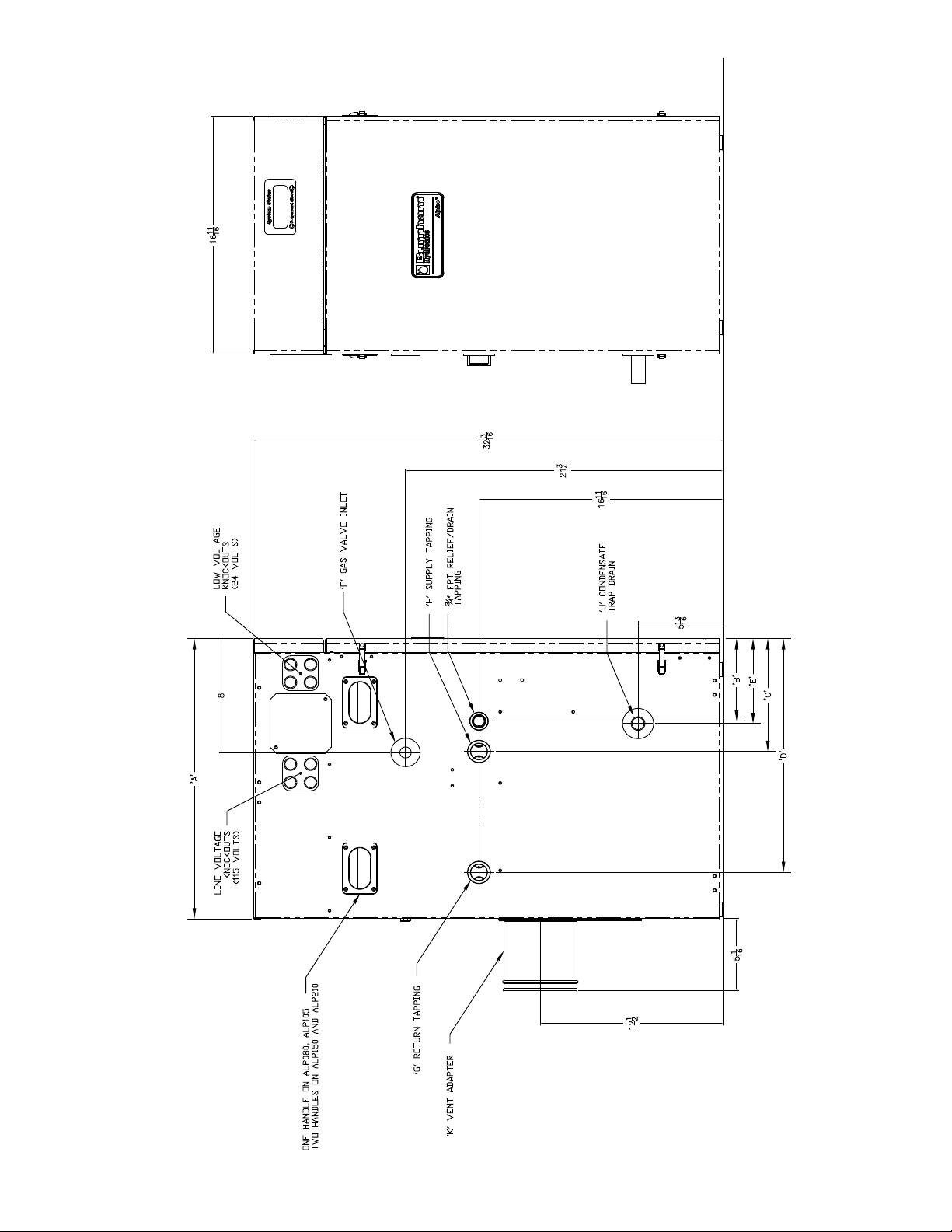
Figure 1a: alpine™ - Models aLP080 thru aLP210
5
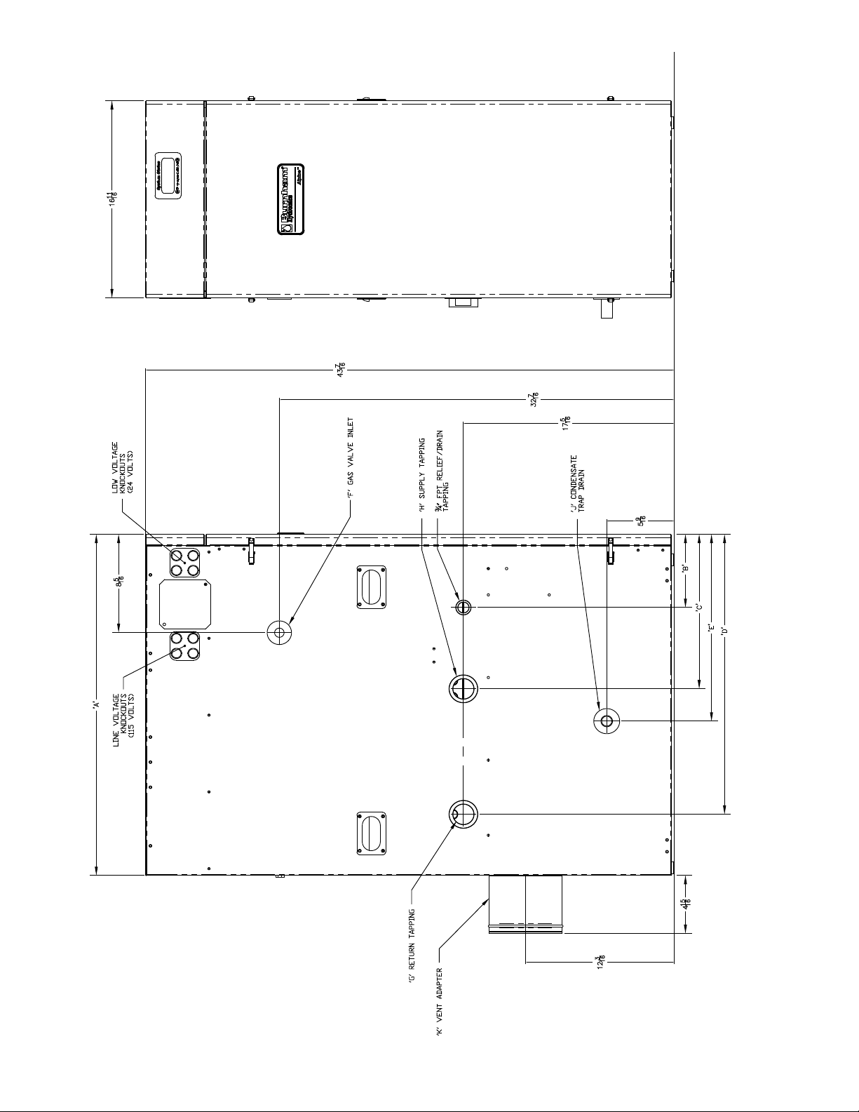
Figure 1B: alpine™ - Models aLP285 thru aLP399
6

Table 2a: Rating Data - Models aLP080 thru aLP399 (0 to 2000 Feet Elevation above Sea Level)
alpine Series gas-Fired Boilers
* Model
Number
ALP080 16 80 73 63 95 0.6 7.3
ALP105 21 105 96 83 95 0.7 9.1
ALP150 30 150 138 120 95 1.3 16.4
ALP210 42 210 194 169 95 1.7 21.8
ALP285 57 285 265 230 95 2.4 29.1
ALP399 80 399 377 328 94.1 94.5 3.4 41.8
(MBH)
Min. Max.
** Output
(MBH)
Input
Net I=B=R
Ratings
Water (MBH)
AFUE
%
Thermal
Efciency
(%)
Combustion
Efciency (%)
Boiler Water
Volume
(Gal.)
Heat Transfer
Area
(Sq. Ft.)
* Add Sufx “N” for Natural Gas or Sufx “P” for LP Gas Models.
notes: ** DOE Heating Capacity (ALP080 thru ALP285); Gross Output (ALP399)
Maximum Working Pressure, Water - 30 PSI Shipped from Factory (std.); 50 PSI - Optional (ALP080 thru ALP285)
Maximum Working Pressure, Water - 50 PSI Shipped from Factory (std.); (ALP399)
Maximum Allowable Temperature, Water - 210°F
Boilers are factory shipped as Natural Gas builds and have to be eld adjusted for LP gas application. Refer to ‘System Start-
Up Section of this manual for detailed procedure.
Ratings shown are for installations at sea level and elevations up to 2000 Feet. For elevations above 2000 Feet, ratings should be
reduced at the rate of four percent (4%) for each 1000 Feet above sea level.
Table 2B: Rating Data - Models aLP080 thru aLP399 (2001 to 7000 Feet Elevation above Sea Level)
alpine Series gas-Fired Boilers
Model
Number *
ALP080 27 80 73 63 95 0.6 7.3
ALP105 35 105 96 83 95 0.7 9.1
ALP150 50 150 138 120 95 1.3 16.4
ALP210 70 210 194 169 95 1.7 21.8
ALP285 57 285 265 230 95 2.4 29.1
ALP399 80 399 377 328 94.1 94.5 3.4 41.8
(MBH)
Min. Max.
** Output
(MBH)
* Add Sufx “N” for Natural Gas or Sufx “P” for LP Gas Models.
notes: ** DOE Heating Capacity (ALP080 thru ALP285); Gross Output (ALP399)
Maximum Working Pressure, Water - 30 PSI Shipped from Factory (std.); 50 PSI - Optional
Maximum Allowable Temperature, Water - 210°F
Boilers are factory shipped as Natural Gas builds and have to be eld adjusted for LP gas application. Refer to ‘System Start-
Up Section of this manual for detailed procedure.
For elevations above 2000 Feet, ratings should be reduced at the rate of four percent (4%) for each 1000 Feet above sea level.
Input
Net I=B=R
Ratings
Water (MBH)
AFUE
%
Thermal
Efciency
(%)
Combustion
Efciency (%)
Boiler Water
Volume
(Gal.)
Heat Transfer
Area (Sq. Ft.)
7

ii. Pre-installation
WaRning
if you do not follow these instructions exactly,
a re or explosion may result causing property
damage or personal injury.
DangER
Do not install boiler where gasoline or other
ammable vapors or liquids, or sources of
hydrocarbons (i.e. bleaches, cleaners, chemicals,
sprays, paint removers, fabric softeners, etc.) are
used or stored.
nOTiCE
Due to the low water content of the boiler, missizing of the boiler with regard to the heating
system load will result in excessive boiler cycling
and accelerated component failure. Burnham
DOES nOT warrant failures caused by mis-sized
boiler applications. DO nOT oversize the boiler to
the system. Modular boiler installations greatly
reduce the likelihood of boiler oversizing.
A. Installation must conform to the requirements of the
authority having jurisdiction. In the absence of such
requirements, installation must conform to the National
Fuel Gas Code, NFPA 54/ANSI Z223.1, and/or CAN/
CSA B149.1 Installation Codes.
B. Appliance is design certied for installation on
combustible ooring. Do not install boiler on
carpeting.
C. Provide clearance between boiler jacket and
combustible material in accordance with local re
ordinance. Refer to Figure 2 for minimum listed
clearances from combustible material. Recommended
service clearance is 24 inches from left side, front, top
and rear of the boiler. Recommended front clearance
may be reduced to the combustible material clearance
providing:
1. Access to boiler front is provided through a door or
removable front access panel.
2. Access is provided to the condensate trap located
underneath the heat exchanger.
D. Install on level oor. For basement installation provide
a solid base such as concrete, if oor is not level or if
water may be encountered on oor around boiler. Floor
must be able to support weight of boiler, water and all
additional system components.
E. Protect gas ignition system components from water
(dripping, spraying, rain, etc.) during boiler operation
and service (circulator replacement, condensate trap,
control replacement, etc.).
F. Provide combustion and ventilation air in accordance
with applicable provisions of local building codes,
or: USA - National Fuel Gas Code, NFPA 54/ANSI
Z223.1, Air for Combustion and Ventilation;
Canada - Natural Gas and Propane Installation Code,
CAN/CSA-B149.1, Venting Systems and Air Supply for
Appliances.
WaRning
Adequate combustion and ventilation air must
be provided to assure proper combustion.
G. The boiler should be located so as to minimize the
length of the vent system. The PVC combustion
air piping, or the optional concentric vent piping,
containing integral combustion air inlet piping, must
terminate where outdoor air is available for combustion
and away from areas that may contaminate combustion
air. In particular, avoid areas near chemical products
containing chlorines, chloro/uorocarbons, paint
removers, cleaning solvents and detergents. Avoid
areas containing saw dust, loose insulation bers, dry
wall dust etc.
CaUTiOn
avoid operating this boiler in an environment
where saw dust, loose insulation bers, dry wall
dust, etc. are present. if boiler is operated under
these conditions, the burner interior and ports
must be cleaned and inspected daily to insure
proper operation.
8

Figure 2: Clearances To Combustible and non-combustible Material
iii. Unpacking Boiler
CaUTiOn
Do not drop boiler.
A. Move boiler to approximate installed position.
B. Remove all crate fasteners.
D. Remove boiler from cardboard positioning sleeve on
shipping skid.
WaRning
installation of this boiler should be undertaken
only by trained and skilled personnel from a
qualied service agency.
C. Lift and remove outside container.
E. Move boiler to its permanent location.
9
iV. Venting
WaRning
Failure to vent this boiler in accordance with these instructions could cause products of combustion to
enter the building resulting in severe property damage, personal injury or death.
Do not interchange vent systems or materials unless otherwise specied.
The use of thermal insulation covering pipe and ttings is prohibited.
Do not use a barometric damper, draft hood or vent damper with this boiler.
The use of CPVC is required when venting in chase ways and through interior wall penetrations.
Do not locate vent termination where exposed to prevailing winds. Moisture and ice may form on
surface around vent termination. To prevent deterioration, surface must be in good repair (sealed,
painted, etc.).
Do not locate vent termination where chlorines, chloro/uorocarbons (CFC’s), petroleum distillates,
detergents, volatile vapors or other chemicals are present. Severe boiler corrosion and failure will
result.
The use of cellular core PVC (
Do not locate vent termination under a deck.
Do not reduce size of vent/combustion air pipe diameter.
When installing vent pipe through chimney, no other appliance can be vented into the chimney.
Do not allow low spots in the vent where condensate may pool.
aSTM F891) is prohibited.
A. Vent Guidelines Due to Removal of an Existing
Boiler
For installations not involving the replacement of an
existing boiler, proceed to Step B.
When an existing boiler is removed from a common
venting system, the common venting system is likely
to be too large for proper venting of the remaining
appliances. At the time of removal of an existing
boiler, the following steps shall be followed with each
appliance remaining connected to the common venting
system placed in operation, while the other appliances
remaining connected to the common venting system are
not in operation:
1. Seal any unused openings in the common venting
system.
2. Visually inspect the venting system for proper
size and horizontal pitch and determine there is no
blockage or restriction, leakage, corrosion, and other
deciencies which could cause an unsafe condition.
3. Insofar as is practical, close all building doors and
windows and all doors between the space in which
the appliances remaining connected to the common
venting system are located and other spaces of the
building. Turn on clothes dryers and any appliance
not connected to the common venting system.
Turn on any exhaust fans, such as range-hoods and
bathroom exhausts, so they will operate at maximum
speed. Do not operate a summer exhaust fan. Close
replace dampers.
4. Place in operation the appliance being inspected.
Follow the Lighting (or Operating) Instructions.
Adjust therm
continuously.
5. Test for spillage at the draft hood relief opening
after ve (5) minutes of main burner operation. Use
the ame of a match or candle, or smoke from a
cigarette, cigar or pipe.
6. After it has been determined that each appliance
remaining connected to the common venting system
properly vents when tested as outlined above, return
doors, windows, exhaust fans, replace dampers and
any other gas burning appliance to their previous
conditions of use.
7. Any improper operation of the common venting
system should be corrected so the installation
conforms with the National Fuel Gas Code, NFPA
54/ANSI Z223.1. When resizing any portion of the
common venting system, the common venting
system should be resized to approach the minimum
size as determined using the appropriate tables in
Part II in the National Fuel Gas Code, NFPA 54/
ANSI Z223.1.
ostat so appliance will operate
B. General Guidelines
1. Vent system installation must be in accordance
with National Fuel Gas Code, NFPA 54/ANSI
Z221.3 or applicable provisions of local building
codes. Contact local building or re ofcials about
restrictions and installation inspection in your area.
10
2. The Alpine™ is designed to be installed as a Direct
Vent boiler. The air for combustion is supplied
directly to the burner enclosure from outdoors and
ue gases are vented directly outdoors (through wall
or roof).
3. The following combustion air/vent system options
are approved for use with the Alpine™ boilers:
i. Two-Pipe CPVC/PVC Gas Vent/Combustion
Air System (factory standard) - separate
CPVC/PVC pipe serves to expel products of
combustion and separate PVC pipe delivers fresh
outdoor combustion air. Refer to Paragraph C
through F for specic details.
ii. Combination Concentric Gas Vent/
Combustion Air Inlet (optional) - the assembly
consists of inner re resistant polypropylene
vent pipe and outer steel pipe casing. The inner
pipe serves as conduit to expel products of
combustion, while outdoor fresh combustion air
is drawn through the space between the inner and
outer pipes. Refer to Paragraphs G through P for
specic details.
4. Refer to Table 3 and the appropriate drawings to
determine the proper conguration of either factory
standard or optional venting/combustion air system
details.
C. The following information is applicable for Two-
Pipe CPVC/PVC Gas Vent/Combustion Air System
(factory standard).
WaRning
all CPVC vent components (supplied with boiler)
must be used for near-boiler vent piping before
transitioning to Schedule 40 PVC pipe (aSTM
2665) components for remainder of vent system.
CPVC vent components must be used prior to
exit of any closet or conned space.
See
Table 6 for complete list of Burnham Vent
System Components. Use single wall thimble
[Burnham Part No. 102180-01 (3”), 102181-01 (4”)]
when penetrating a combustible wall for vent only.
Horizontal vent pipe must maintain a minimum ¼
1.
inch per foot slope down towards boiler.
2. Use noncombustible ¾ inch pipe strap to support
horizontal runs and maintain vent location and slope
while preventing sags in pipe. Maximum support
spacing is four (4) feet. Avoid low spots where
condensate may pool. Do not penetrate any part of
the vent system with fasteners.
WaRning
all condensate that forms in the vent must be
able to drain back to the boiler.
3.
Vent length restrictions are based on equivalent
length of vent/combustion air pipe (total length
of straight pipe plus equivalent length of ttings).
Maximum vent/combustion air lengths are listed in
Table 7. Do not exceed maximum vent/combustion
air lengths. Table 6 lists equivalent lengths for
ttings. Do not include vent/combustion air
terminals in equivalent feet calculations. See
“Combustion Air/Vent, Equivalent Length Work
Sheet”.
4. Provide minimum service clearance between boiler
back and concentric vent exiting through outside
wall, for concentric vent installation/replacement
and/or ue temperature sensor service/replacement.
5. Do not install venting system components on
the exterior of the building except as specically
required by these instructions. The vent termination
location is restricted as follows (refer to Figures 6
and 9):
a.
Minimum twelve (12) inches above grade plus
normally expected snow accumulation level, or
seven (7) feet above grade, if located adjacent
Table 3: Combustion air/Vent System Options
Option Description
TWO-PiPE
CPVC/PVC
HORizOnTaL
TWO-PiPE
CPVC/PVC
ERTiCaL
V
COnCEnTRiC
HORizOnTaL
COnCEnTRiC
VERTiCaL
Direct Vent (sealed combustion) with both the vent pipe and
combustion air pipe terminating horizontally (through a sidewall)
with individual penetrations for the vent and combustion air
piping and terminals.
Direct Vent (sealed combustion) with both the vent pipe and
combustion air pipe terminating vertically (through the roof) with
individual penetrations for the vent and combustion air piping
and terminals.
Direct Vent (sealed combustion) the concentric vent pipe
terminates horizontally (through a sidewall).
Direct Vent (sealed combustion) the concentric vent pipe
terminates vertically (through the roof).
additional
Vent Kit
Required
no See Table 4 See Figure 6
no See Table 4
o See Table 9 See Figure 13
n
Yes See Table 9 See Figure 19
Components
included with
Boiler
installation
Drawing and
Specication
See Figures
9 and 10
11
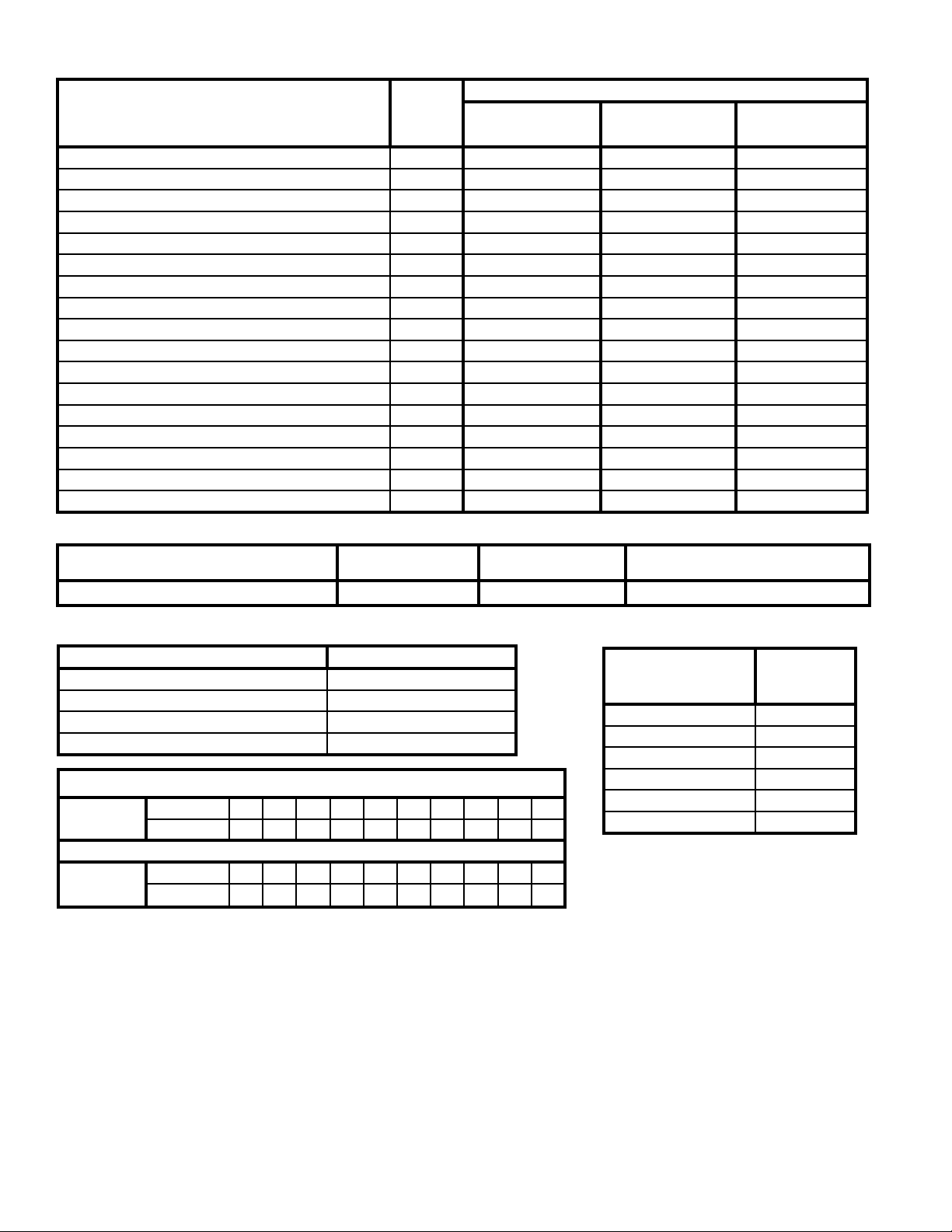
Table 4: Vent System Components included with Boiler
Vent System Components
3” Schedule 40 PVC Tee Combustion Air/Vent Terminal 102190-01 2 1 ---
4” Schedule 40 PVC Tee Combustion Air/Vent Terminal 102190-02 --- 1 2
3” Stainless Steel Rodent Screens 102191-01 2 1 --4” Stainless Steel Rodent Screens 102191-02 --- 1 2
3” x 30” Schedule 40 CPVC Pipe 102193-01 1 1 --4” x 30” Schedule 40 CPVC Pipe 102193-02 --- --- 1
3” Schedule 80 CPVC 90° Elbow 102192-01 1 1 ---
4” Schedule 80 CPVC 90° Elbow 102192-02 --- --- 1
8 oz. Bottle of Transition Cement 102195-01 1 1 1
8 oz. Bottle of Primer 102194-01 1 1 1
Burnham Vent Supplement Manual 102188-01 1 1 1
Two Pipe Vent System Connector for CPVC/PVC 102183-01 1 --- --Two Pipe Vent System Connector for CPVC/PVC 102183-02 --- 1 --Two Pipe Vent System Connector for CPVC/PVC 102183-03 --- --- 1
Two Pipe Vent System Connector for CPVC/PVC Gasket 102185-01 1 1 ---
Two Pipe Vent System Connector for CPVC/PVC Gasket 102185-02 --- --- 1
Silicone Vent Sensor Cap 102153-01 1 1 1
Part
Number
ALP080 & ALP105
(P/N 102189-01)
ALP150 & ALP210
(P/N 102189-02)
ALP285 & ALP399
(P/N 102189-03)
Table 5: Clearances from Vent Piping to Combustible Material
Quantity
Vent Pipe Pipe Direction Enclosure
CPVC/PVC Venting Vertical or Horizontal Enclosed at all Sides 1” Vent/0” Combustion Air
Minimum Clearance To
Combustible Material, Inches
Table 6: Burnham Vent System and Combustion air System Components
Vent System Component Equivalent Length (Ft.)
3” Schedule 40 CPVC Pipe x 30 Inches 2.5
4” Schedule 40 CPVC Pipe x 30 Inches 2.5
3” Schedule 80 CPVC 90° Elbow 5
4” Schedule 80 CPVC 90° Elbow 5
Maximum Number of 90’s and Straight Pipe
Vent Pipe
Combustion
Air Pipe
b. Minimum three (3) feet above any forced
c. Direct Vent - Minimum one (1) foot below, one
d. Minimum four (4) feet horizontally from electric
# of 90’s 1 2 3 4 5 6 7 8 9 10
Feet of Pipe 55 50 45 40 35 30 25 20 15 10
# of 90’s 1 2 3 4 5 6 7 8 9 10
Feet of Pipe 55 50 45 40 35 30 25 20 15 10
to public walkway. Do not install over public
walkway where local experience indicates
appliance ue gas vapor or condensate creates a
nuisance or hazard.
combustion air located within ten (10) feet.
(1) foot horizontally from, or one (1) foot above
any door, window, or gravity air inlet.
meters, gas meters, regulators, and relief valves.
This distance may be reduced if equipment is
protected from damage due to condensation or
vapor by enclosure, overhangs, etc.
e. Minimum twelve (12) inches from overhang or
corner of building.
6. Enclose vent passing through occupied or
unoccupied spaces above the boiler with material
having a re resistance rating of at least equal to the
rating of the adjoining oor or ceiling. Maintain
minimum clearances to combustible materials. See
Figure 2 and Table 5 for details.
Combustion Air
System Component
(Parts by Others)
3” or 4” ID Pipe x 1 Ft. 1
3” or 4” ID Pipe x 2 Ft. 2
3” or 4” ID Pipe x 4 Ft. 4
3” or 4” ID Pipe x 5 Ft. 5
3” or 4” 90° Elbow 5
3” or 4” 45° Elbow 5
*Equivalent Feet of Pipe Based on
Standard 4” PVC Design
Equivalent
Feet of Pipe*
12
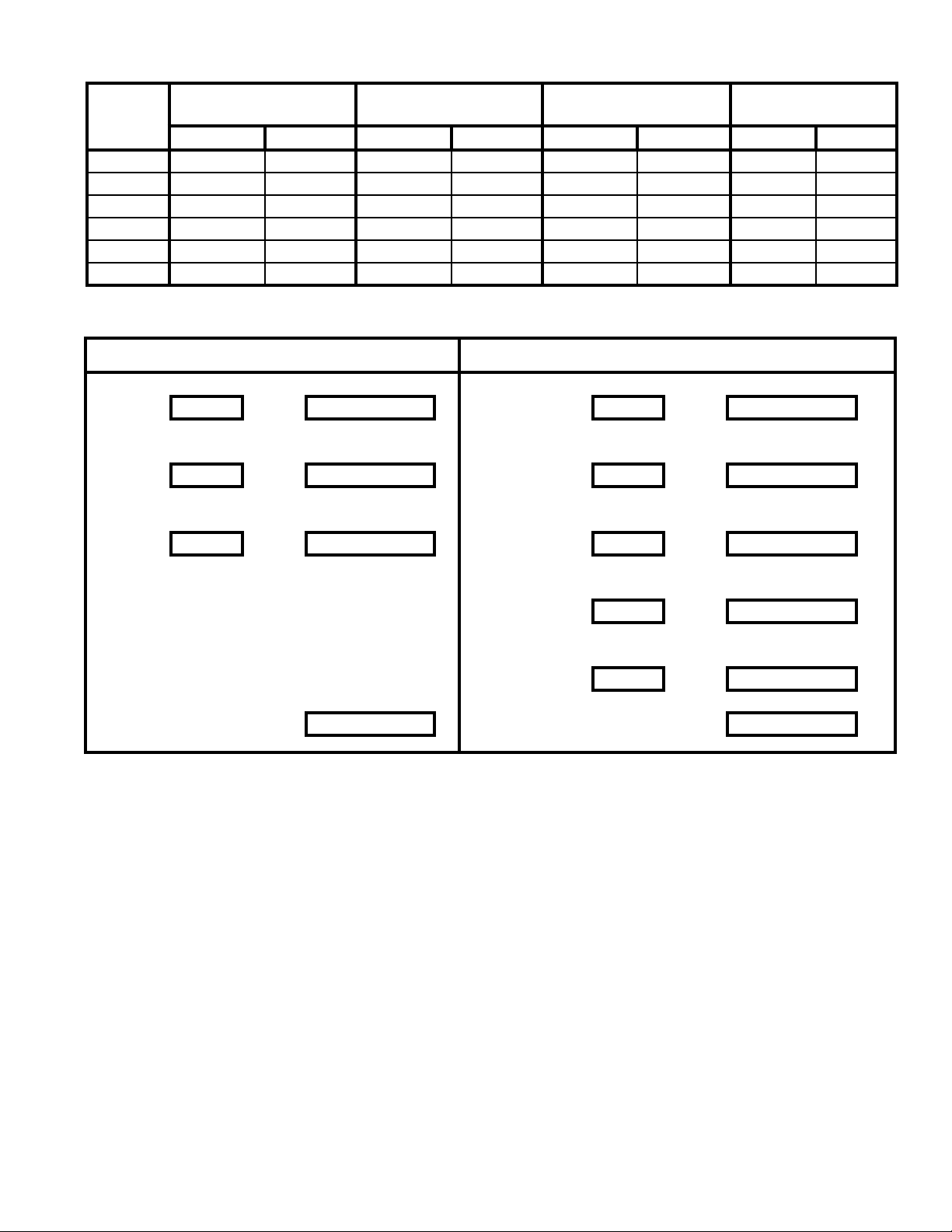
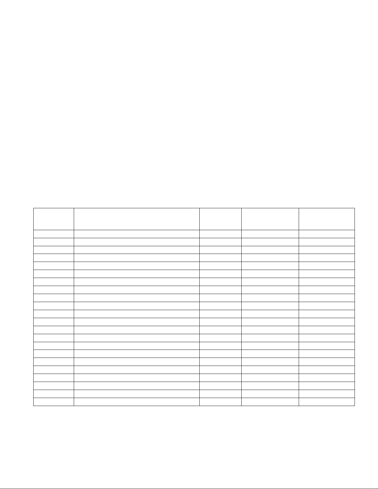
Table 7: Vent/Combustion air Pipe Length
Boiler
Model
ALP080 21-7/8 In. 60 Ft. --- --- 21-7/8 In. 60 Ft. --- --ALP105 21-7/8 In. 60 Ft. --- --- 21-7/8 In. 60 Ft. --- --ALP150 --- --- 21-7/8 In. 60 Ft. 21-7/8 In. 60 Ft. --- --ALP210 --- --- 21-7/8 In. 60 Ft. 21-7/8 In. 60 Ft. --- --ALP285 --- --- 32 In. 60 Ft. --- --- 32 In. 60 Ft.
ALP399 --- --- 32 In. 60 Ft. --- --- 32 In. 60 Ft.
3” Combustion Air Pipe
(Equivalent Length)
Min. Max. Min. Max. Min. Max. Min. Max.
4” Combustion Air Pipe
(Equivalent Length)
3” Vent Pipe
(Equivalent Length)
4” Vent Pipe
(Equivalent Length)
Combustion Air/Vent, Equivalent Length Work Sheet
This sheet is supplied to assist in vent/combustion air, equivalent length calculating
Combustion air Vent
90° elbow(s) PVC Supplied 30” straight CPVC
Quantity = x 5’ = equiv. ft. a. Length ft. = 2.5 x 1 = 2.5 equiv. ft. a.
45° elbow(s) PVC Supplied 90° elbow CPVC
Quantity = x 2.5’ = equiv. ft. b. Quantity = 1 x 5’ = 5 equiv. ft. b.
Straight pipe PVC 90° elbow(s) PVC
Length ft. = x 1 = equiv. ft. c. Quantity = x 5’ = equiv. ft. c.
45° elbow(s) PVC
Quantity = x 2.5’ = equiv. ft. d.
Straight pipe PVC
Length ft. = x 1 = equiv. ft. e.
Total* a.+b.+c. = equiv. ft. Total* a.+b.+c.+d.+e.= equiv. ft.
* Total cannot exceed 60 equiv. ft. length.
Vent and combustion air terminals do not count towards total equiv. ft.
Note: For one or two family dwellings, re
resistance rating requirement may not need to be
met, but is recommended.
7. Plan venting system to avoid possible contact with
plumbing or electrical wires. Start at vent connector
at rear of boiler and work towards vent termination.
8. Design the Vent System to allow a 3/8” of thermal
expansion per 10 feet of CPVC/PVC pipe. Runs of
20 ft. or longer that are restrained at both ends must
use an offset or expansion loop. Refer to Figure 3.
9. Follow all manufacturer instructions and warnings
when preparing pipe ends for joining and using the
primer and the cement.
D. Installation of Two-Pipe CPVC/PVC Gas Vent/
Combustion Air System Connector
The boiler two pipe vent system connector for CPVC/
PVC and gasket are shipped inside the vent carton. The
vent connector mounting hardware - six (6) #8 x ½”
black oxide round head Phillips sheet metal screws - are
shipped inside Miscellaneous Part Carton.
1. Remove the vent connector and gasket from the vent
carton.
2. Locate six mounting screws.
3. Position the vent connector and gasket onto jacket
combination rear/bottom panel and insert vent
connector inner stainless steel vent pipe into the heat
exchanger vent outlet.
4. Align vent connector plate and gasket clearance
holes with rear/bottom panel engagement holes; then
secure the collar and gasket to rear/bottom panel
with six mounting screws. See Figure 4.
5. Flue temperature sensor, factory attached to the
boiler wiring harness, is secured to the boiler rear/
bottom panel with tape.
13
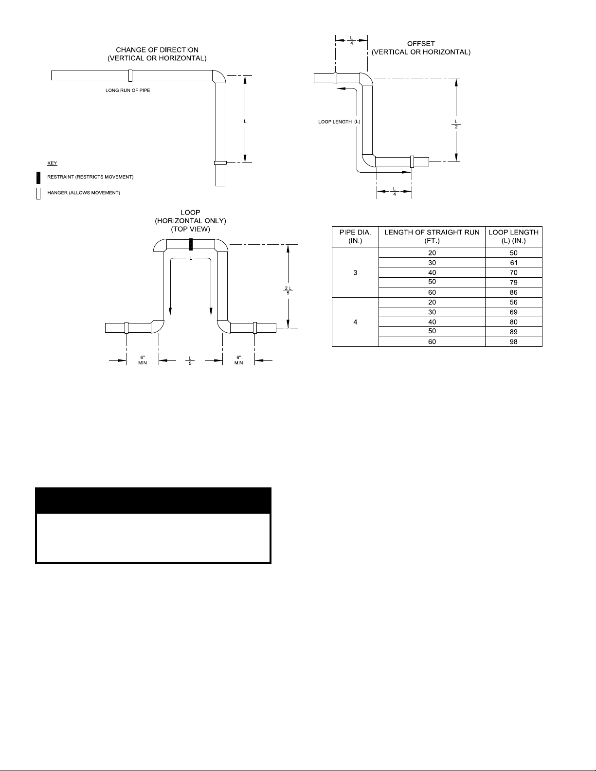
Figure 3: Expansion Loop and Offset
6. Remove the Silicone ue sensor cap from the vent
carton and press onto the two pipe vent system
connector for CPVC/PVC sensor port. Remove
the tape holding the ue sensor and insert the ue
temperature sensor into the ue sensor plug until it
is rmly engaged. See Figure 4.
7. Near-Boiler Vent Piping (see Figure 5):
WaRning
all CPVC vent components (supplied with boiler)
must be used for near-boiler vent piping before
transitioning to Schedule 40 PVC pipe (aSTM
2665) components for remainder of vent system.
a. All CPVC vent components (supplied with
boiler), 30” straight and 90° elbow, must be
used for near-boiler piping before transitioning
to Schedule 40 PVC (ASTM 2665) pipe
components for remainder of vent system.
The CPVC 30” straight section may be cut to
accommodate desired vent conguration for
near-boiler piping, provided both pieces are used
in conjunction with the CPVC 90° elbow, before
any PVC components are used. Ensure that the
CPVC elbow is the rst elbow used in the vent
system as it exits the boiler.
14
b.
Clean all vent and combustion air pipe joints
with primer and secure with transition cement,
(8 oz. bottle of primer and 8 oz. bottle of
transition cement supplied with boiler). Follow
the instructions provided on the primer and
cement.
E. CPVC/PVC Horizontal Venting System
See Figures 3 thru 8.
Vent Piping - Horizontal
1. See Paragraph D for instructions on attaching the
vent system connector to the boiler.
2. Do not exceed maximum vent length. Refer to
Table 7 for pipe diameters and allowable lengths.
3. Horizontal vent pipe must maintain a minimum ¼
inch per foot slope down towards boiler.
4. Use appropriately designed thimbles when passing
through combustible walls (thimble use is optional
for noncombustible walls). Insert thimble through
wall from outside. Secure outside ange to wall
with nails or screws, and seal ID, OD and vent holes
with sealant material. Install inside ange to inside
wall, secure with nails or screws, and seal with
sealant material.
5. For noncombustible wall application when thimble
is not used, size opening such that a minimal
clearance is obtained.
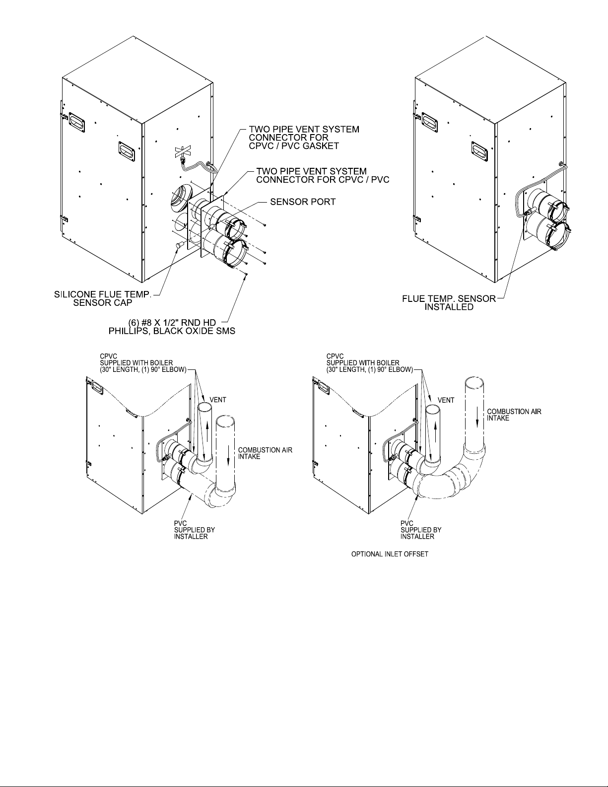
Figure 4: Field installation of Two Pipe Vent System Connector for CPVC/PVC
Figure 5: near-Boiler Vent/Combustion air Piping
6. Install Rodent Screen and Vent Terminal (supplied
with boiler), see Figure 8 for appropriate
conguration.
7. Apply sealant between vent pipe and opening/
thimble to provide weather-tight seal. Sealant
should not restrain the expansion of the vent pipe.
Combustion Air Piping - Horizontal
1. See Paragraph D for instructions on attaching the
vent system connector to the boiler.
2. Do not exceed maximum combustion air length.
Refer to Table 7 for pipe diameters and allowable
lengths.
3. Horizontal combustion air pipe must maintain a
minimum ¼ inch per foot slope down towards
terminal, when possible. If not, slope toward boiler.
4.
It is strongly recommended to locate the combustion
air terminal on the same wall as the vent termination
to prevent nuisance boiler shutdowns. Combustion
air terminal can be installed closer to wall than vent.
5. Start at vent connector (rear boiler jacket) and work
towards the combustion air terminal.
6. Size combustion air wall penetration to allow easy
insertion of combustion air piping.
15
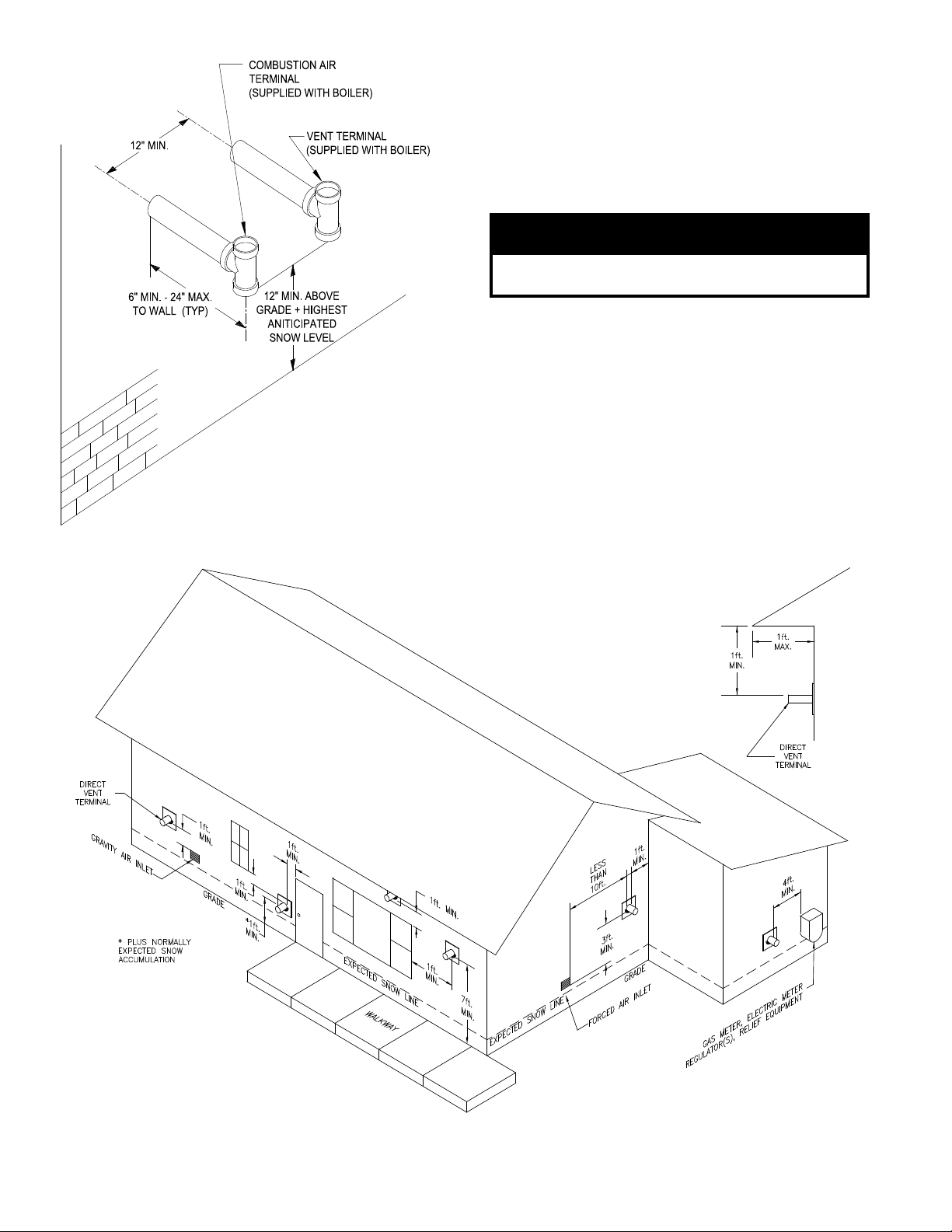
Figure 6 : Direct Vent - Side Wall Terminations
7. Install Rodent Screen and Combustion Air Terminal
(supplied with boiler), see Figure 8 for appropriate
conguration.
8. Apply sealant between vent pipe and opening to
provide weather-tight seal
F. CPVC/PVC Vertical Venting System
Refer to Figures 3, 4, 5, 8, 9 & 10.
nOTiCE
Roof penetrations require the use of roof ashing
and storm collar that are not supplied with boiler.
Vent Piping - Vertical
1. See Paragraph D for instructions on attaching the
vent system connector to the boiler.
2. Do not exceed maximum vent length. Refer to
Table 7 for pipe diameters and allowable lengths.
3. Horizontal vent pipe must maintain a minimum ¼
inch per foot slope down towards boiler.
4. Install re stops where vent passes through oors,
ceilings or framed walls. The re stop must close
the opening between the vent pipe and the structure.
5. Whenever possible, install vent straight through the
roof. Refer to Figures 9 and 10.
16
Figure 7: Location of Vent Terminal Relative to Windows, Doors, grades,
Overhangs, Meters and Forced air inlets (Combustion air Terminal not shown)

Figure 8: Rodent Screen
a. Size roof opening to maintain minimum
clearance of 1 inch from combustible materials.
b. Extend vent pipe to maintain minimum vertical
and horizontal distance of twelve (12) inches
from roof surface. Allow additional vertical
distance for expected snow accumulation.
Provide brace as required.
CaUTiOn
Vertical venting requires the use of roof ashing
and a storm collar to prevent moisture from
entering the structure.
c. Install storm collar on vent pipe immediately
above ashing. Apply Dow Corning Silastic 732
RTV Sealant between vent pipe and storm collar
to provide weather-tight seal.
6.
Install Rodent Screen and Vent Terminal (supplied
with boiler), see Figure 8 for appropriate
conguration.
installation
Figure 9: Direct Vent - Vertical Terminations
Figure 10: Direct Vent - Vertical Terminations with Sloped Roof
Extend vent/combustion air piping to maintain minimum vertical (‘X’) and minimum horizontal (‘Y’) distance of
twelve (12) inches (18 inches Canada) from roof surface. a
snow accumulation.
llow additional vertical (‘X’) distance for expected
17
7. Brace exterior piping if required.
Combustion Air Piping - Vertical
1. See Paragraph D for instructions on attaching the
vent system connector to the boiler.
2. Do not exceed maximum combustion air length.
Refer to Table 7 for pipe diameters and allowable
lengths.
3. Horizontal combustion air pipe must maintain a
minimum ¼ inch per foot slope down towards
boiler.
4. Locate combustion air termination on the same roof
location as the vent termination to prevent nuisance
boiler shutdowns. Combustion air terminal can be
installed closer to roof than vent.
5. Start at vent connector on burner enclosure (rear
boiler jacket) and work towards the combustion air
terminal.
6. Size roof opening to allow easy insertion of
combustion air piping and allow proper installation
of ashing and storm collar to prevent moisture
from entering the structure.
a. Use appropriately designed vent ashing
when passing through roofs. Follow ashing
manufacturers’ instructions for installation
procedures.
b. Extend combustion air pipe to maintain
minimum vertical and horizontal distance of
twelve (12) inches from roof surface. Allow
additional vertical distance for expected snow
accumulation. Provide brace as required.
c. Install storm collar on combustion air pipe
immediately above ashing. Apply Dow
Corning Silastic 732 RTV Sealant between
combustion air pipe and storm collar to provide
weather-tight seal.
7. Install Rodent Screen and Combustion Air Terminal
(supplied with boiler), see Figure 8 for appropriate
conguration.
8. Brace exterior piping if required.
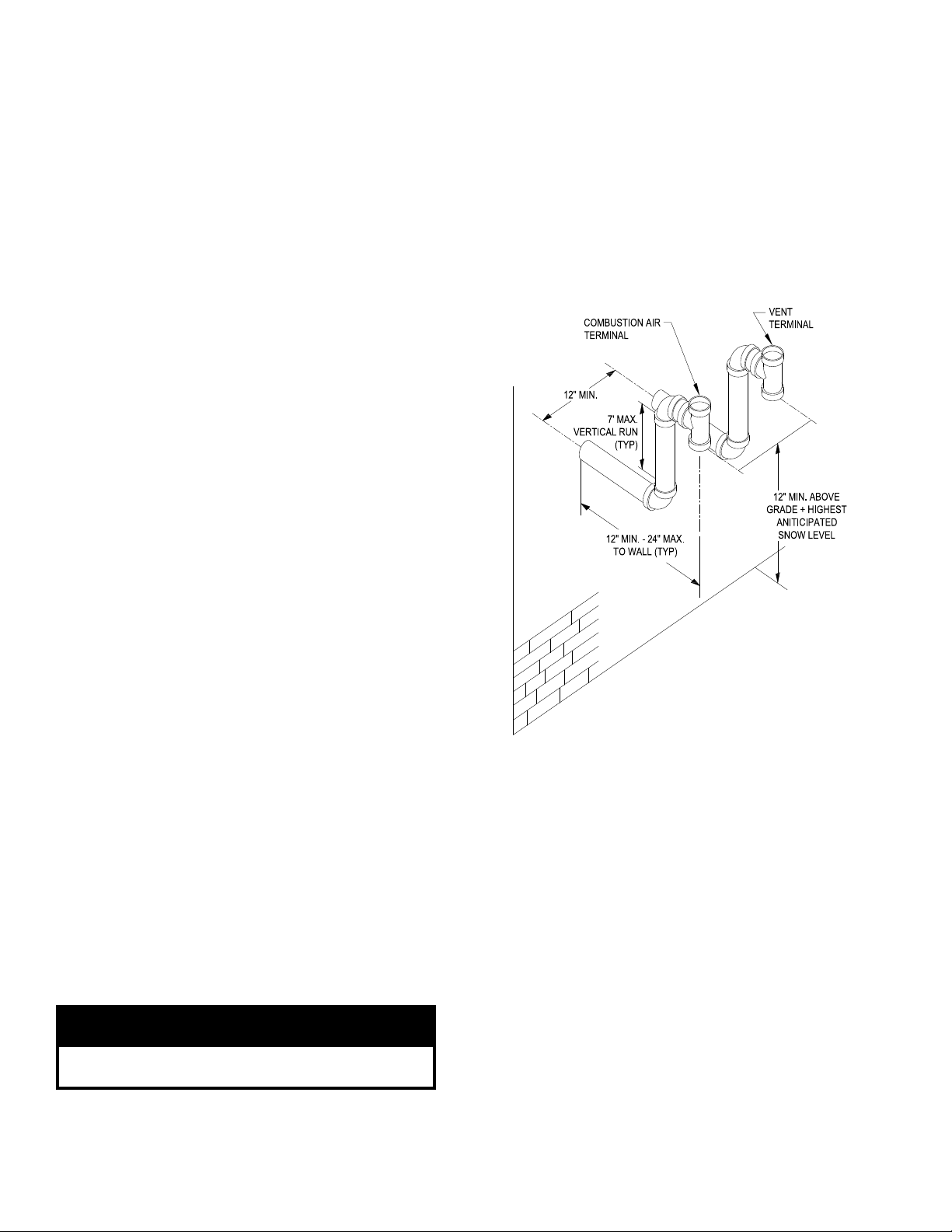
G. Optional Snorkel CPVC/PVC Horizontal Vent
System
Refer to Figures 3, 4, 5, 7, 8 and 11.
This installation will allow a maximum of seven (7) feet
vertical exterior run of the vent/combustion air piping
to be installed on the CPVC/PVC horizontal venting
application (Section E).
nOTiCE
Exterior run to be included in equivalent vent/
combustion air lengths.
18
Vent Piping - Snorkel
1. See Paragraph D for instructions on attaching the
vent system connector to the boiler.
2. Do not exceed maximum vent length. Refer to
Table 7 for pipe diameters and allowable lengths.
3. Horizontal vent pipe must maintain a minimum ¼
inch per foot slope down towards boiler
4. After penetrating wall/thimble, install a Schedule
40 PVC 90° elbow so that the elbow leg is in the up
direction.
5. Install maximum vertical run of seven (7) feet of
Schedule 40 PVC vent pipe. See Figure 11.
Figure 11: Direct Vent - Optional Side Wall
Snorkel Terminations
6. At top of vent pipe length install another PVC 90°
elbow so that elbow leg is opposite the building’s
exterior surface.
7. Install Rodent Screen and Vent Terminal (supplied
with boiler), see Figure 8 for appropriate
conguration.
8. Brace exterior piping if required.
Combustion Air Piping - Snorkel
1. See Paragraph D for instructions on attaching the
vent system connector to the boiler.
2. Do not exceed maximum combustion air length.
Refer to Table 7 for pipe diameters and allowable
lengths.
3. Horizontal combustion air pipe must maintain a
minimum ¼ inch per foot slope down towards
terminal, when possible. If not, slope toward boiler.
4. After penetrating wall, install a Schedule 40 PVC
90o elbow so that elbow leg is in the up direction.
Remove the collar from the bag and set aside.
5. Install maximum vertical run of seven (7) feet of
Schedule 40 PVC vent pipe. See Figure 11.
6. At top of vent pipe length install another PVC 90°
elbow so that elbow leg is opposite the building’s
exterior surface.
7. Install Rodent Screen and Combustion Air Terminal
(supplied with boiler), see Figure 8 for appropriate
conguration.
8. Brace exterior piping if required.
H. The following information is applicable for
Combination Concentric Gas Vent/Combustion air
System (optional).
I. Field Installation of Boiler Concentric Vent Collar
The Boiler Concentric Vent Collar is shipped inside the
boiler in plastic bag. The Collar mounting hardware
- six (6) #8 x ½” black oxide round head Phillips sheet
metal screws - are shipped inside Miscellaneous Part
Carton.
1.
Release four side draw latches and remove boiler
lower front door assembly to gain access to the Vent
Collar.
Table 8: Concentric Vent Components
Part Number Component Description Size
101493-01 90° Elbow – Long Radius 80/125 mm 5.5
101491-01 45° Elbow - Long Radius 80/125 mm 3.0
101163-01 Cut -To-Length Extension, 500 mm (19-1/2”) 80/125 mm 1.63 **Can be cut
101162-01 Cut -To-Length Extension, 1000 mm (39”) 80/125 mm 3.25 **Can be cut
101485-01 Fixed Extension, 2000 mm (78”) 80/125 mm 3.25 ***Must not be cut
101808-01 Horizontal (Wall) Terminal 80/125 mm *NA Supplied with boiler
101495-01 Vertical Roof Terminal 80/125 mm *NA See Note 1
101496-01 Flat Roof Flashing 80/125 mm
101497-01 Sloped Roof Flashing 80/125 mm See Note 2
101492-01 Support Elbow with Chimney Chase Bracket 80/125 mm 8.5 See Note 3
101498-01 Hanger Wall Bracket 80/125 mm
101548-01 90° Elbow – Long Radius 100/150 mm 8.0
101549-01 45° Elbow - Long Radius 100/150 mm 3.0
101550-01 1 Cut -To-Length Extension, 500 mm (19-1/2”) 100/150 mm 1.63 ** Can be cut
101551-01 Cut -To-Length Extension, 1000 mm (39”) 100/150 mm 3.25 ** Can be cut
101553-01 Fixed Extension, 2000 mm (78”) 100/150 mm 6.5 *** Must not be cut
101809-01 Horizontal (Wall) Terminal 100/150 mm * NA Supplied with boiler
101557-01 Vertical (Roof) Terminal 100/150 mm * NA See Note 1
101558-01 Flat Roof Flashing 100/150 mm
101559-01 Sloped Roof Flashing 100/150 mm See Note 2
101560-01 Support Elbow with Chimney Chase Bracket 100/150 mm 10.0 See Note 3
101561-01 Hanger Wall Bracket 100/150 mm
otes:
n
* NA – do not include vent terminal into total vent length calculations.
** These sections have plain male end and beaded female end. See Figure 11 for details.
*** These sections have beaded male end and beaded female end. See Figure 12 for details.
1. Vertical terminal can be used with either of the roof ashings listed beneath it.
2. Sloped roof ashing suitable for roof angles between 25° and 45°.
3. Used at base of vertical run inside unused masonry chimney.
2.
3. Locate and remove six mounting screws.
4. Position the Collar onto jacket combination rear/
bottom panel and insert collar inner stainless steel
vent pipe into the heat exchanger vent outlet.
Align collar plate clearance holes with rear/bottom
5.
panel engagement holes; then secure the collar to
rear/bottom panel with six mounting screws. See
Figure 12.
6. Flue temperature sensor, factory attached to the
boiler wiring harness, is secured to the boiler rear/
bottom panel with tape.
7. Remove the tape and push the sensor rubber plug
into Concentric Vent Collar sensor port until the
plug is securely engaged. See Figure 12.
The installation of the Concentric Vent Collar is now
completed.
J. General Guidelines - Concentric Venting
1. Vent system installation must be in accordance
with National Fuel Gas Code, NFPA 54/ANSI
Z221.3 or applicable provisions of local building
Component
Equivalent Vent
Length, Ft
Comments
19

Figure 12: Field installation of Boiler Concentric Vent Collar
codes. Contact local building or re ofcials about
restrictions and installation inspection in your area.
2.
Horizontal vent pipe must maintain a minimum ¼
inch per foot slope towards the boiler.
3. Use noncombustible ¾ inch pipe strap to support
horizontal runs and maintain vent location and
slope while preventing sags in pipe. Do not restrict
thermal expansion or movement of vent system.
Maximum support spacing is ve (5) feet. Do not
penetrate any part of the vent system with fasteners.
4. Vent length restrictions are based on equivalent
length of vent pipe i.e. total length of straight pipe
plus equivalent length of ttings. See Table 11
for specied vent length details. Do not exceed
maximum vent length. Table 8 lists available
concentric vent components and includes equivalent
vent length for ttings. Do not include vent terminal
into total vent length calculations.
Table 9: Vent System Components included with Boiler
Vent System Components Part Number
80/125mm Horizontal (Wall) Terminal (ALP080 thru ALP210) 101808-01
100/150mm Horizontal (Wall) Terminal (ALP285 thru ALP399) 101809-01
5. Provide and maintain vent pipe minimum clearances
to combustible material. See Figure 2 and Table 10
for details.
6. Provide minimum service clearance between boiler
back and concentric vent exiting through outside
wall, for concentric vent installation/replacement
and/or ue temperature sensor service/replacement,
as follows:
a. For horizontal venting where supplied
Concentric Vent Terminal is attached directly to
installed Boiler Concentric Vent Collar - 6 inches
b. For vertical venting where optional Concentric
Vent 90° long radius elbow is attached to
installed Boiler Concentric Vent Collar - 18
inches
7. Do not install venting system components on the
exterior wall of the building except as specically
required by these instructions. Refer to Figure 7.
Table 10: Clearances from Vent Piping to Combustible Material
Vent Pipe Pipe Direction Enclosure
CPVC/PVC Venting Vertical Or Horizontal Enclosed at All Sides 1” Vent/0” Combustion Air
20
Minimum Clearance To
Combustible Material, Inches
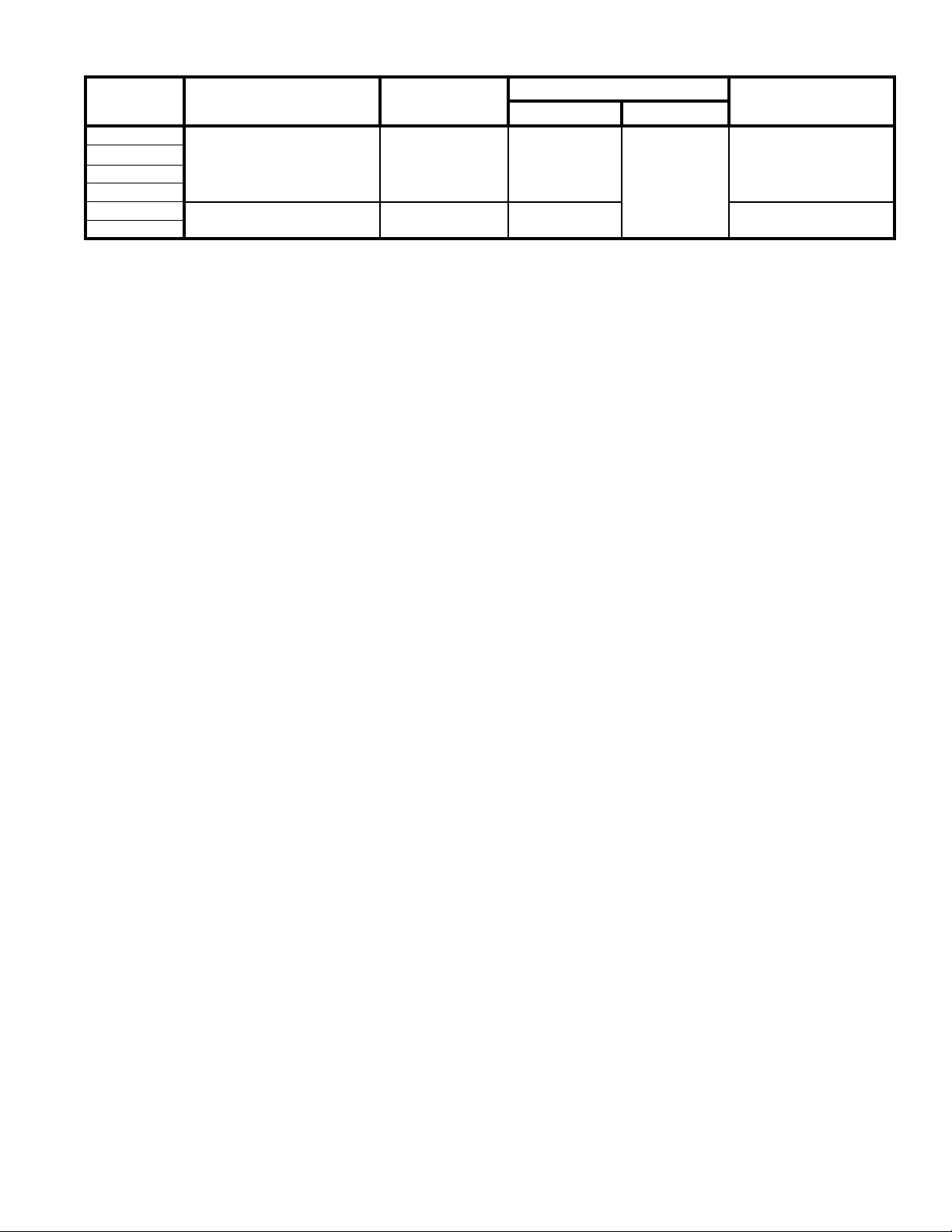
Table 11: Concentric Vent Length
Boiler Model Concentric Vent
ALP080
ALP105
ALP150
ALP210
ALP285
ALP399
ote: * With optional concentric vent components. See Table 10 for details.
n
Factory Supplied
Horizontal (Wall) Terminal
Factory Supplied
Horizontal (Wall) Terminal
Inner/Outer Pipe
Dia., mm
80/125 mm 21-7/8 in
100/150 mm 32 in 6-1/2 in
The direct vent termination location is restricted as
follows:
a. Minimum twelve (12) inches above grade plus
normally expected snow accumulation level, or
minimum seven (7) feet above grade, if direct
vent terminal is located adjacent to public
walkway. Do not install the terminal over public
walkway where local experience indicates that
appliance ue gas vapor or condensate creates a
nuisance or hazard.
b. Minimum three (3) feet above any forced air
inlet located within ten (10) feet.
c. Minimum four (4) feet horizontally from electric
meters, gas meters, regulators and relief valves.
This distance may be reduced if equipment is
protected from damage due to ue gas vapor or
condensation by enclosure, overhang, etc.
d. Minimum twelve (12) inches below, above or
horizontally from any air opening into a building
(window, door or gravity air inlet).
e. Minimum twelve (36) inches horizontally from a
building corner.
f. Minimum twelve (12) inches vertically from any
roof overhang twelve (12) inches or less wide.
If a roof overhang width exceeds twelve (12)
inches the terminal vertical clearance must be
increased to avoid ue vapor condensation.
8. Enclose vent passing through occupied or
unoccupied spaces above the boiler with material
having a re resistance rating of at least equal to the
rating of the adjoining oor or ceiling. Maintain
minimum clearances to combustible materials. See
Figure 2.
Note: For one or two family dwellings, re
resistance rating requirement may not need to be
met, but is recommended.
9. Plan venting system to avoid possible contact with
plumbing or electrical wires. Start at vent connector
on top of boiler and work towards vent terminal.
Concentric Venting - Horizontal Venting
1. Permitted terminals for horizontal venting:
Horizontal (Wall) Terminal, either 80/125 mm (P/N
101808-01) or 100/150 mm (P/N 101809-01) - see
Table 8.
Vent Length
Minimum * Maximum
Total of 60
Equivalent ft.
Wall Opening Diameter
5-1/2 in
2. Concentric Vent components supplied with the boiler
are packed inside boiler carton and include the
following:
a. 80/125 mm Horizontal (Wall) Terminal, Part
Number 101808-01
• Horizontal (Wall) Terminal consists of
Straight section having plain male end with
locking band clamp installed; Terminal
Assembly with offset vent termination,
and Outside Wall Plate, both riveted
on the opposite end; overall length is
approximately 28-1/8”.
• Separate Inside Wall Plate
• Two Hardware Bags (each bag contains
four screws and four anchors) to attach vent
terminal Outside Wall Plate to exterior wall
and Inside Wall Plate to interior wall.
b. 100/150 mm Horizontal (Wall) Terminal, Part
Number 101809-01
• Horizontal Concentric Vent Terminal, which
consists of Straight section having plain
male end with locking band clamp installed;
Terminal Assembly with offset vent
termination, and Outside Wall Plate, both
riveted on the opposite end); overall length
is approximately 31-1/8”.
• Separate Inside Wall Plate.
• Two Hardware Bags (each bag contains
four screws and four anchors) to attach vent
terminal Outside Wall Plate to exterior wall
and Inside Wall Plate to interior wall.
14. Installation of the Boiler Concentric Vent Collar is
covered in Section I above. See Figure 12.
15. For horizontal (side wall) installation, the Horizontal
(Wall) Terminal will extend past outer wall surface
either by 4-1/4” (80/125 mm), or, 5-1/2” (100/150
mm). See Figure 13 “Horizontal (Wall) Terminal
Installation”.
17. For horizontal venting, to install the Horizontal
(Wall) Terminal:
a. Cut a 5-1/2” diameter hole through the exterior
wall opening (for 80/125 mm concentric vent) or
6-1/2” diameter hole (for 100/150 mm concentric
vent) at the planned location of the horizontal
terminal.
21
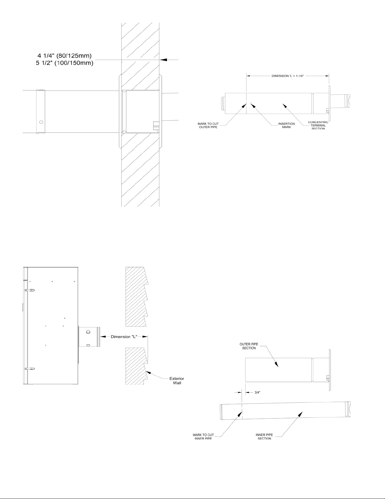
Figure 13: Horizontal (Wall) Terminal installation
b. Measure dimension “L” from exterior wall outer
surface to the end of the last tting (or end of
installed Boiler Concentric Vent Collar). See
Figure 14 ‘Dimension “L”’.
several marks around the outer pipe to establish a
cut line. See Figure 15 ‘ Cutting Outer Pipe’.
d. Carefully cut the outer pipe at the marked line
using aviation shears, a hacksaw etc. Ensure the
pipe is cut square and cut end is deburred.
Figure 15: Cutting Outer Pipe
Mark the end of the Horizontal (Wall) Terminal
e.
inner polypropylene vent pipe to extend ¾” past
the cut end of the outer pipe. To achieve a square
cut of the inner pipe, place several marks around
the inner pipe to establish a cut line.
f.
Cut off the marked end of inner polypropylene
vent pipe with a ne tooth blade hacksaw etc.
and deburr. See Figure 16 “Cutting Inner Pipe.
g. Place a mark around the outer pipe, 1” from cut
edge, towards the attached Outside Wall Plate, to
establish visual insertion line as shown in Figure
16 “Cutting Inner Pipe”.
h. Pass the shortened Horizontal Concentric Vent
from outside, thru earlier cut exterior wall
opening and push in until the attached Outside
Wall Plate is tight against exterior wall surface.
Insure the proper position of the Horizontal
Concentric Vent before securing the Outside Wall
Plate to the wall with provided fasteners. Seal
plate edges with exterior grade sealant to prevent
moisture penetration.
22
Figure 14: Dimension “L”
When factory supplied Horizontal (Wall)
c.
Terminal needs to be shortened, measure
dimension “L” plus 1-¼” from inside of the
attached Outside Wall Plate and mark the
Horizontal (Wall) Terminal outer pipe. To
achieve a square cut of the outer pipe, place
Figure 16: Cutting
inner Pipe

WaRning
The terminal vent portion is offset towards the top
inside the outer pipe of the Horizontal Concentric
Vent Terminal to provide vent pipe pitch towards
the boiler for condensate removal.
See Figure 17 ‘Horizontal (Wall) Terminal Detail’.
it is imperative to properly mount the vent
terminal.
The terminal orientation label is located on the
inside of the terminal Outside Wall Plate. insure
the vent terminal is positioned as shown in
Figure 18 before securing the Outside Wall Plate
to exterior wall.
CaUTiOn
Exterior wall surface must be reasonably at to
attach the Outside Wall Plate. When exterior wall
surface is not at (covered with vinyl or wood
shingle siding etc.) the siding must be removed,
and a at surface build up ash or above siding
exterior surface to secure/seal the terminal
Outside Wall Plate.
Concentric Venting - Vertical Venting
For vertical (through the roof) venting, extend
Vertical (Roof) Terminal to maintain minimum 12
inches vertical and horizontal distance from building
roof surface. Allow additional vertical distance
for expected snow accumulation. Provide brace as
required. See Figure 19 ‘Vertical Concentric Vent
Installation’.
1. For vertical venting, where optional Concentric Vent
90° degree long radius elbow is attached to installed
Boiler Concentric Vent Collar, to install elbow:
a. Remove locking band clamp off the terminal and
set aside.
b. Lubricate the brown gasket inside boiler
concentric vent collar with small amount of
water.
c. Ensure that male end of the elbow inner plastic
pipe is evenly engaged into the gasket all around,
then, push the elbow male end inside boiler
concentric vent collar until the bead on male end
of elbow outer pipe bottoms out inside boiler
vent collar.
Figure 17: Horizontal (Wall) Terminal Detail
i. Install the supplied Inside Wall Plate onto the
shortened Horizontal (Wall) Terminal interior
end and move the plate to cover interior wall
cut opening. Secure the plate with provided
fasteners, then, apply the sealant around plate
sides to seal it to interior wall.
j. Lubricate the brown gasket inside boiler
concentric vent collar or the last section of the
vent pipe with small amount of water.
k. Ensure that inner pipe of the terminal is evenly
engaged into the gasket all around, then push the
termination male end inside boiler concentric
vent collar or the last section of the vent pipe,
until the mark (see Step g) is no longer visible.
l. Re-install locking band clamp onto the joint
to secure the terminal to the collar or the last
section of the vent pipe.
Figure 18: Completing Horizontal (Wall)
erminal installation
T
d. Re-install locking band clamp onto the joint to
secure the elbow to the collar.
e.
Continue installing additional concentric vent
cuttable or non-cuttable piping as required.
2. Additionally, secure elbow to boiler vent collar with
three evenly spaced #8 x ½” sheet metal screws.
Use collar rivets as reference attachment points.
Mark (center punch) each screw location off each
rivet centerline 5/8” towards collar-beaded end. See
Figure 18 ‘Completing Horizontal (Wall) Terminal
Installation’ for details. Drill 1/8” hole thru both
23
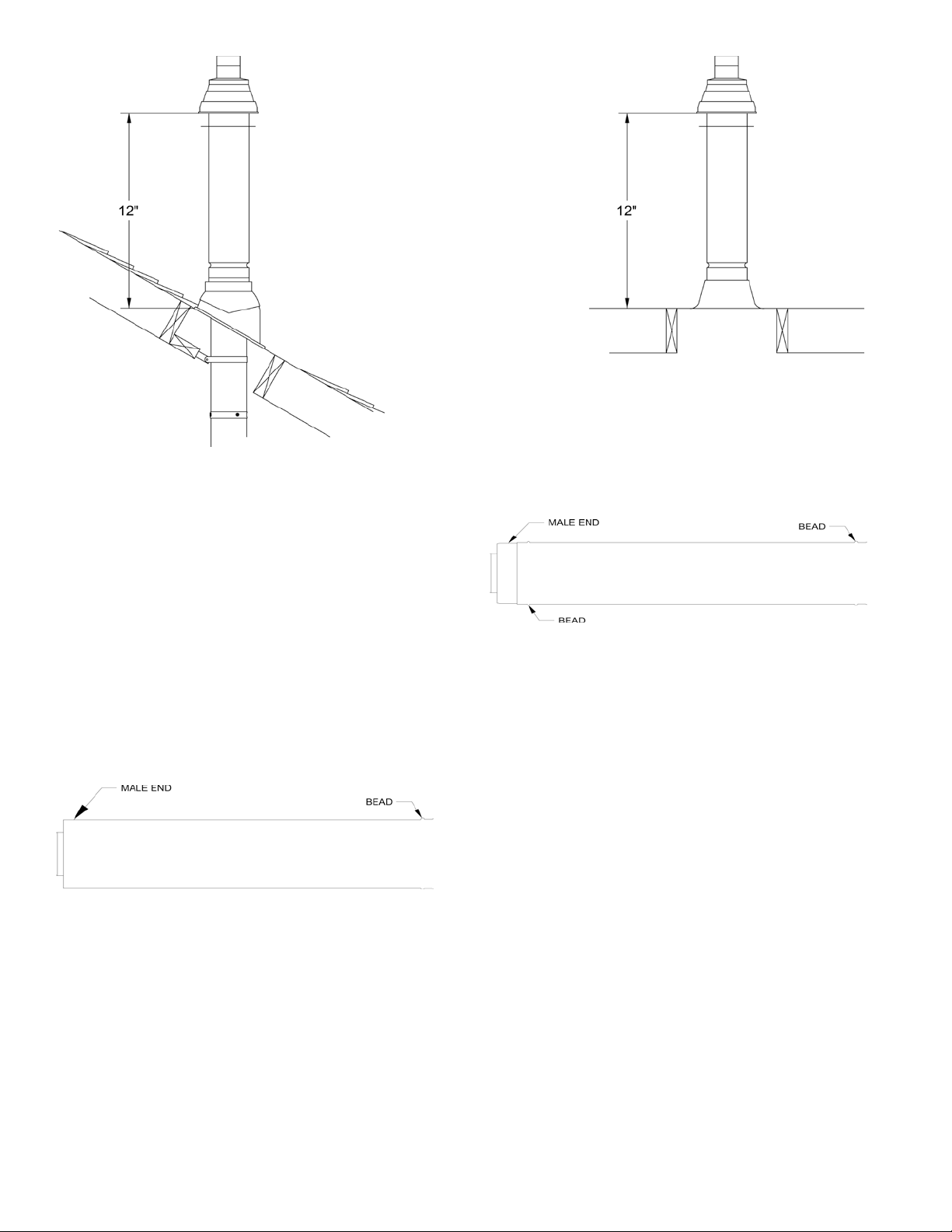
Figure 19: Vertical Concentric Vent installation
outer pipes to start the screw. Use a drill stop or
other means to ensure that the drill bit does not
penetrate more than 3/8” into the outer pipe. Do
not use sheet metal screws longer than ½”.
When Additional Concentric Vent Piping is
needed
1. If additional concentric vent piping is needed:
a. Concentric Vent Cut-To-Length Extension pipes,
identied in Tables 8 and 10 CAN BE CUT
to required length when used as an extension.
These pipes have plain male end and beaded
female end. Always cut the pipe from plain
male end. See Figure 20 ‘Cut-To-Length
Extension (Cuttable)”.
Figure 20: Cut-To-Length Extension (Cuttable)
b. The remaining Concentric Vent Fixed Extensions
shown in Table 8 CANNOT BE CUT. These
pipes have beaded male and beaded female ends.
See Figure 21 ‘Fixed Extension (Non-Cuttable)’.
2. To cut the Concentric Vent Straight pipe to required
length refer to Figure 22 “Cutting Straight Pipe” and
follow the procedure below:
a. Determine the required length of the outer pipe.
When doing this allow an additional 1” of length
for insertion into the female end of the adjoining
pipe. Mark the cut line on the outer pipe.
Figure 21: Fixed Extension (non-Cuttable)
b.
Remove the plastic inner pipe by pulling it out
from the female end.
Cut the OUTER PIPE ONLY at the point
c.
marked in Step (a) using aviation shears, a
hacksaw, or an abrasive wheel cutter. Be careful
to cut the pipe square. Deburr the cut end with a
le or emery cloth.
d. Make an insertion mark 1” from the male end of
the outer pipe.
e. Cut the plastic inner pipe so that it will protrude
3/8” beyond the male end of the outer pipe when
reinstalled in the outer pipe. Use a ne tooth
hacksaw or a PvC saw to cut the plastic pipe and
be careful to cut the pipe square. Deburr the cut
edge of the plastic pipe with a le, razor blade or
ne sandpaper.
f. Reinstall the inner pipe.
3. To join Concentric Vent Pipe refer to Figure 23
“Joining Cuttable Pipe” and Figure 24 “Joining
Non-Cuttable Pipe” and follow the procedure below:
a. Start assembly of the vent system at the boiler.
Lubricate the brown gasket in the boiler vent
collar with a few drops of water.
24
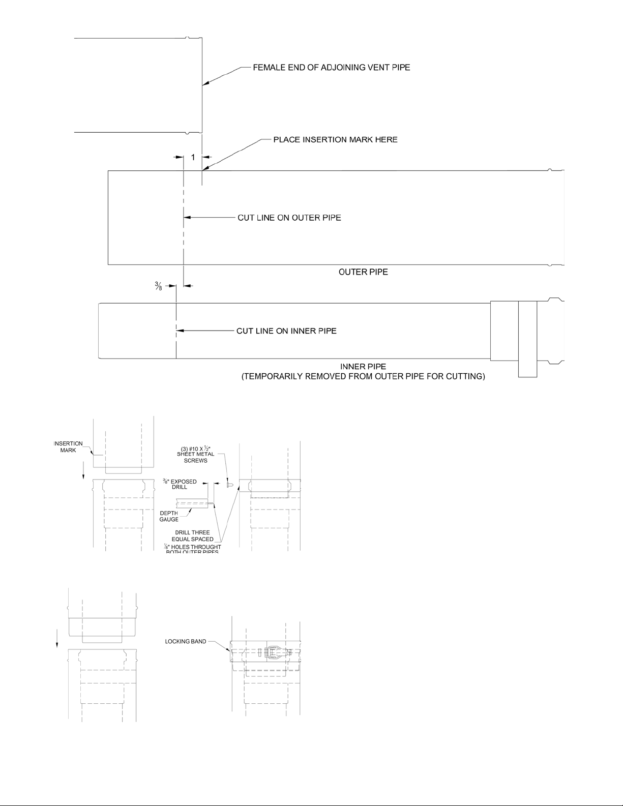
Figure 22: Cutting Straight Pipe
Figure 23: Joining Cuttable Pipe
Figure 24: Joining non-Cuttable Pipe
b. Push the male end of the rst tting into the
boiler collar until it bottoms out. The male end
of cuttable sections should go 1” into the collar
until the insertion mark (made in Step 2d above)
is covered. On other ttings, the bead on the
male pipe will be bottom out on the collar (see
Figure 24).
c.
The male end of cuttable ttings must be held to
the collar with three (3) #10 x 1/2” sheet metal
screws. Drill a 1/8 hole through both outer pipes
to start this screw. Use a drill stop or other
means to ensure that the drill bit does not
penetrate more than 3/8” into the outer pipe.
Do not use a sheet metal screw longer than
1/2” (see Figure 23).
d. Use locking bands (provided with all ttings) to
secure non-cuttable pipe, as well as ttings, to
the boiler collar (see Figure 24).
e. Use the same method to join all remaining vent
components except for the terminal.
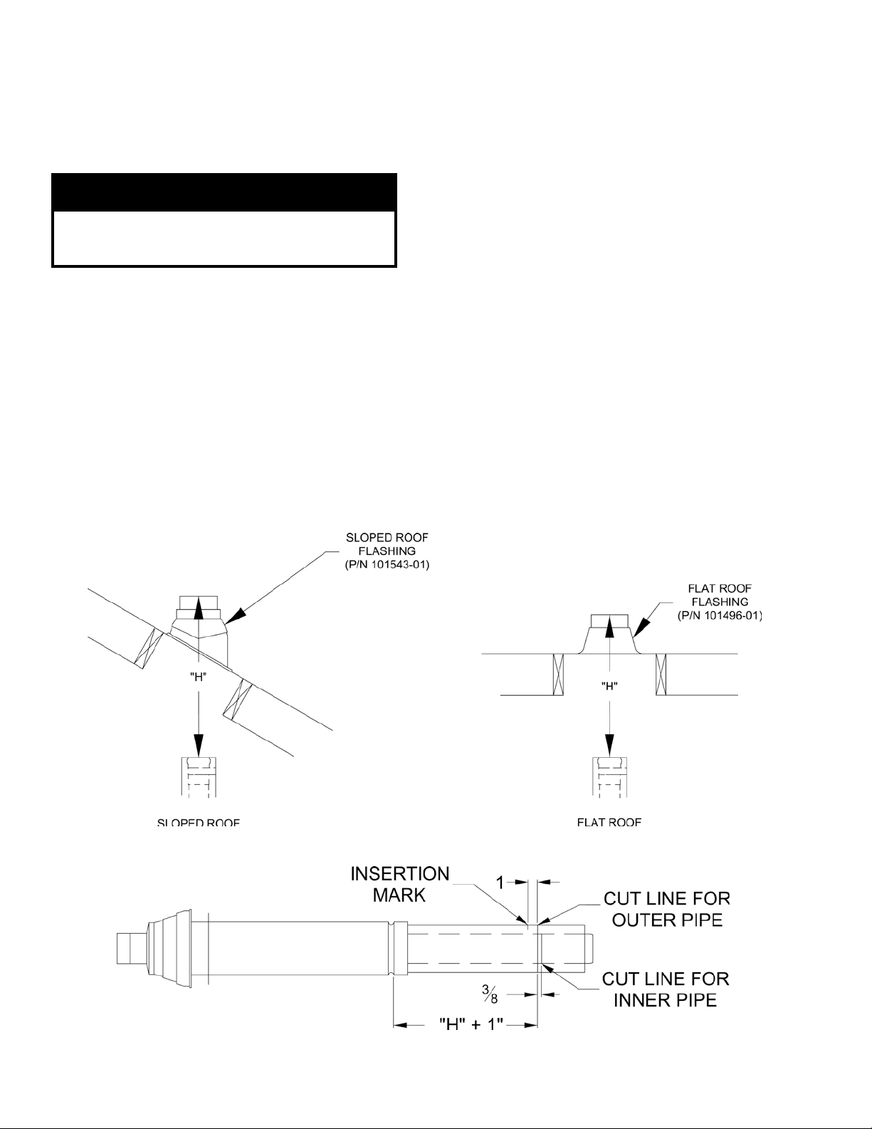
Vertical (Roof Terminal Installation
1. Vertical (Roof) Terminal Installation. Refer to
Figures 26, 27 and 28.
In addition to the vertical terminal, either a Flat
Roof Flashing or Sloped Roof Flashing is required
for this installation. Refer to Table 8 ‘Concentric
Vent Components’ for details.
25
a. Determine the centerline of the terminal location
on the roof. For at roof, cut either 5-1/2”
diameter hole (80/125 mm concentric vent size)
or 6-1/2” diameter hole (100/150 mm concentric
vent size) for the terminal. For sloped roof, cut a
hole in the roof large enough for the terminal to
pass through the roof while remaining plumb.
CaUTiOn
if the boiler is located directly under the hole,
cover it while cutting the hole to prevent debris
from falling onto boiler.
b. Install the roof ashing using standard practice
on the roong system of the structure.
If not already done, assemble the venting system
c.
inside the building. The last section of pipe needs
to be on the same center line as the terminal
and within 19-1/4” of the top edge of the roof
ashing.
Measure distance “H” from the top edge of the
d.
storm collar to the end of the last tting as shown
in Figure 25.
e. Add 1” to distance “H”. Carefully mark this
length on the pipe as shown in Figure 26.
f. Cut the outer pipe only at the point marked in
Step (e) using aviation shears, a hacksaw, or an
abrasive wheel cutter. Be careful to cut the pipe
square. De-burr the cut end with a le or emery
cloth.
g.
Place a mark on the plastic inner pipe 3/8”
beyond the end of the outer pipe (Figure 26).
Use a ne tooth hacksaw to cut the plastic pipe
and be careful to cut the pipe square. De-burr the
cut edge of the plastic pipe with a le or emery
cloth.
h. Make a mark on the terminal section 1” from the
cut end of the outer pipe as shown in Figure 26.
i. Slip the terminal section through the roof from
the outside. Push into the last section of vent
pipe until the mark made in Step (h) is not
longer visible. Secure the terminal to the last
piece of pipe with three #10 x 1/2” sheet metal
screws. Drill a 1/8” hole through both outer
pipes to start these screws. Use a drill stop or
other means to ensure that the drill bit does
not penetrate more than 3/8” into the outer
pipe. Do not use a sheet metal screw longer
than 1/2”.
j. Secure the terminal section to the inside of
the roof structure using the mounting bracket
provided with the terminal (Figure 27).
26
Figure 25: Dimension "H"
Figure 26: Cutting Vertical Terminal
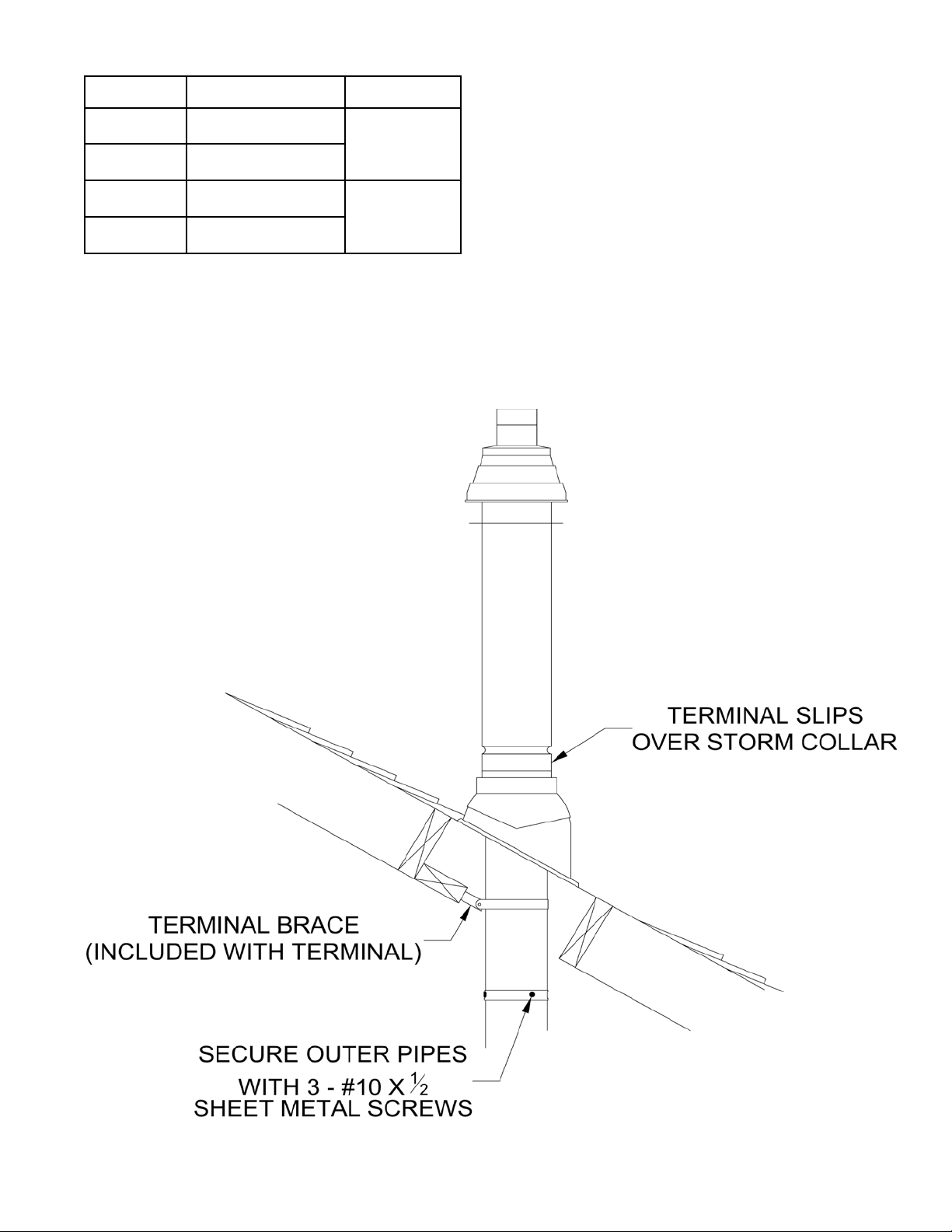
Table 10: Cut-To-Length Extensions (Cuttable)
Part No. Component Description Size
101163-01
101162-01
101550-01
101551-01
Cut-To-Length Extension,
500 mm (19-1/2”)
Cut-To-Length Extension,
1000 mm (39”)
Cut-To-Length Extension,
500 mm (19-1/2”)
Cut-To-Length Extension,
1000 mm (39”)
80/125 mm
100/150 mm
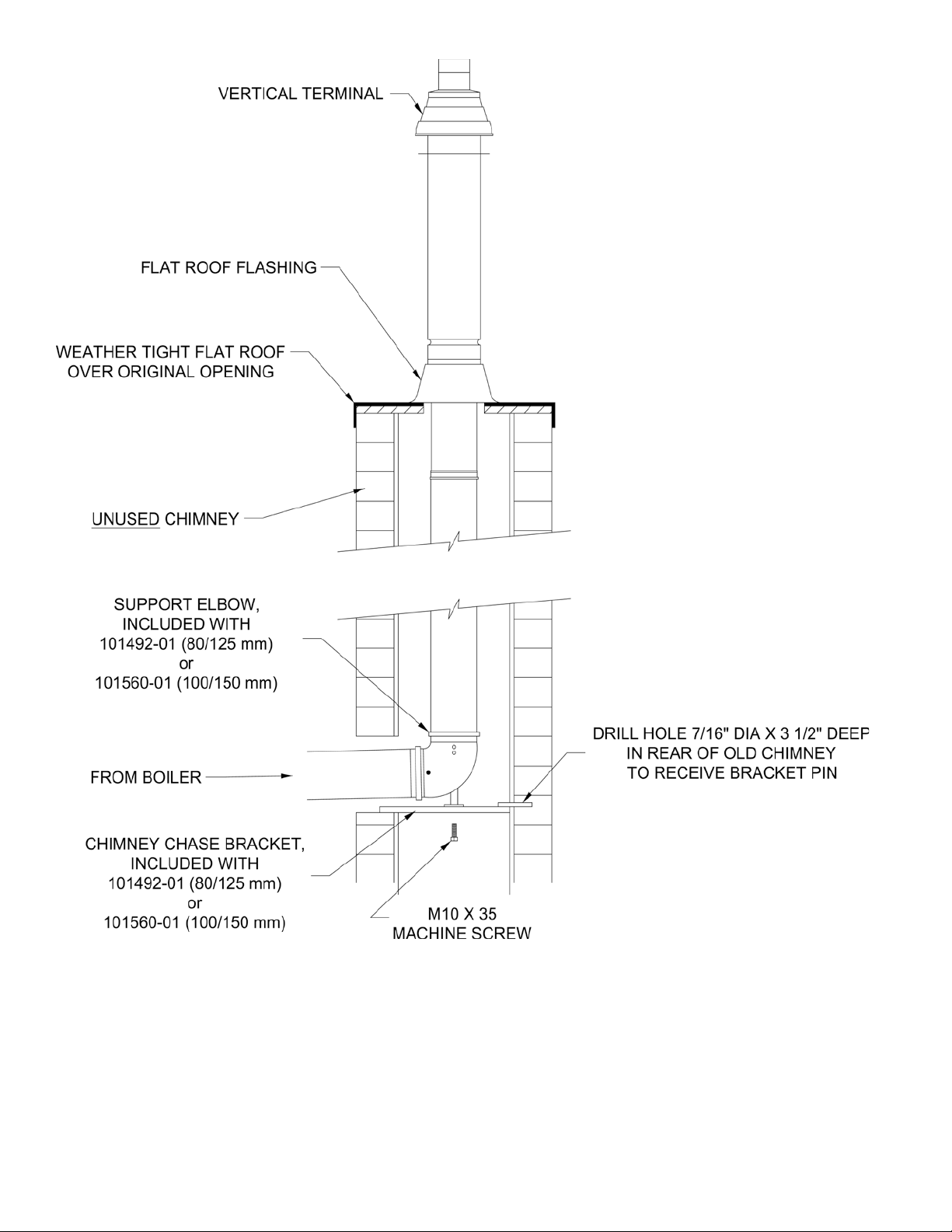
Chimney Chase Installation.
A vertical concentric vent system, either 80/125 mm
or 100/150 mm can be installed in an UNUSED
masonry chimney. Refer to Figure 28.
a. The Chimney chase Support Elbow with
attached Mounting Bracket is used at the base
of the chimney. Refer to Table 8 ‘Concentric
Vent Components’ for details. Slip the elbow
over the M10 x 35 screw in the support bracket.
Determine the desired vertical location of the
support elbow in the chimney and mark the
location of the pin, positioned on the back of
the support bracket, onto the chimney rear wall.
Drill a 7/16” diameter x 3-1/2” deep hole in the
marked location, then, insert the back bracket pin
into the hole. The front of the elbow mounting
bracket should be supported either by bottom of
the opening into chimney or installer supplied
spacer.
b.
Construct a weather-tight at roof to cover
the top of the old chimney. Install the vertical
terminal through this roof using the at roof
ashing.
Figure 27: Completing Vertical Terminal installation
27
28
Figure 28: Chimney Chase installation

V. Condensate Disposal
A. Condensate Trap and Drain Line.
1. All condensate, which forms in the boiler or vent
system, collects in the sump under heat exchanger
and leaves the boiler through factory installed
condensate trap.
2. The trap allows condensate to drain from sump
while retaining ue gases in the boiler. The trap
has factory installed overow switch, which shuts
down the boiler in the event the drain line becomes
obstructed, preventing proper condensate removal.
Refer to Section XIII “Service and Maintenance”
for condensate trap and condensate overow switch
removal and replacement procedure, if required.
3. Note the following when disposing of the
condensate:
a. Condensate is slightly acidic, typical pH around
3.5 - 4.5. Do not use metallic pipe or ttings in
the condensate drain line. Do not route the drain
line through areas that could be damaged by
leaking condensate.
Do not route or terminate the condensate drain
b.
line in arrears subject to freezing temperatures.
c. If the point of condensate disposal is above the
trap, a condensate pump is required to move
the condensate to the drain. Select a condensate
pump approved for use with condensing
furnaces. If overow from the pump would
result in property damage, select a pump with an
overow switch. Wire this switch in series with
installer provided external high limit, to shut off
the boiler, and, if desired, in series with installersupplied alarm, to trigger an alarm in the event
of overow.
d. Do not attempt to substitute another trap for one
provided with the boiler.
e. In order for boiler to work properly, the boiler
must be leveled during installation.
4. The condensate trap stub is located at boiler left
side, below inlet and outlet water pipe connections.
Refer to Figures 1A and 1B.
5. Condensate trap must be lled up with water,
prior to boiler start-up and before connecting any
condensate line to the boiler, to insure combustion
products cannot escape from operating boiler. To ll
the trap, inject water in the amount of 1 cup (8 uid
ounces) through condensate trap stub opening. Do
not overll the trap.
6. If any additional condensate drain line is needed,
construct the extension from PVC or CPVC
Schedule 40 pipe. The factory supplied ¾” x 5-5/8”
long PVC coupling, located in the Part Carton, must
be used to connect drain line to the condensate trap
stub. Do not over tighten coupling compression nuts
when connecting drain line and condensate trap
stub.
WaRning
Failure to install the condensate trap and
condensate drain in accordance with the above
instructions could cause ue gas to enter the
building, resulting in personal injury or death.
CaUTiOn
Boiler condensate is corrosive. Route
condensate drain line in a manner such
that any condensate leakage will not cause
property damage.
Some jurisdictions may require that
condensate be neutralized prior to disposal.
nOTiCE
Use materials approved by the authority having
jurisdiction.
B. Condensate Neutralizer Installation
1. Some jurisdictions may require that the condensate
be neutralized before being disposed of. Follow
local codes pertaining to condensate disposal.
2. A Condensate Neutralizer Kit (P/N 101867-01)
is available as optional equipment. Follow local
codes and instructions enclosed with the kit for
Condensate Neutralizer installation.
3. Limestone chips will get coated by neutral salts
(product of chemical reaction between limestone
and acidic condensate) and lose neutralizing
effectiveness over time. Therefore, periodic
condensate neutralizer maintenance and limestone
chip replacement must be performed. A pH test or
acid test kits are available from HVAC/plumbing
distributors and should be used to measure
condensate acidity before/after neutralizer thus
indicating a need for service and chip replacement.
29

30
Figure 29: Condensate Trap and Drain Line
 Loading...