

Page 1
Commercial Boilers
MULTIPLE - MODULAR
MANUAL
FOR GAS - FIRED BOILER
SERIES 8H / 8HE SIZES 5 THRU 10
This manual must only be used by a qualied heating installer/service technician.
BEFORE installing, read all instructions in this manual and all other information
shipped with the boiler. Post all instructions and manuals near the boiler for
reference by service personnel. Perform steps in the order given. Failure to comply
could result in severe personal injury, death or substantial property damage.
81416022R1 - 3/15
www.burnhamcommercial.com
Price - $5.00
1
Page 2
IMPORTANT INFORMATION -
READ and save these instructions for reference
Hazard definitions
The following dened terms are used throughout this manual to bring attention to the presence of hazards of various
risk levels or to important information concerning the life of the product.
Indicates an imminently hazardous situation
which, if not avoided, will result in death, serious
injury or substantial property damage.
Indicates a potentially hazardous situation which,
if not avoided, could result in death, serious injury
or substantial property damage.
THIS BOILER HAS A LIMITED WARRANTY, A COPY OF WHICH IS PRINTED ON THE BACK OF THIS MANUAL.
It is the responsibility of the installing contractor to see that all controls are correctly installed and are
operating properly when the installation is complete. The warranty for this boiler is valid only if the boiler
has been installed, maintained and operated in accordance with these instructions.
Indicates a potentially hazardous situation which,
if not avoided, may result in moderate or minor
injury or property damage.
Indicates special instructions on installation,
operation, or maintenance which are important
but not related to personal injury hazards.
DO NOT store or use gasoline or other ammable vapors or liquids in the vicinity of this or any other
appliance.
If you smell gas or fuel oil vapors, do not try to operate the burner/boiler system. Do not touch any
electrical switch or use any phone in the building. Immediately call the gas or oil supplier from a remotely
located phone.
Burner/boiler systems produce steam or hot water in a pressurized vessel by mixing extremely flammable
gaseous, liquid or solid fuels with air to produce combustion and very hot products of combustion.
Explosions, fires severe personal injury, death and/or property damage will result from improper, careless
or inadequate installation, operation or maintenance of fuel-burning and boiler equipment.
2
Page 3

Improper installation, adjustment, alteration, service or maintenance can cause property damage, personal
injury or loss of life. Failure to follow all instructions in the proper order can cause personal injury or
death. Read and understand all instructions, including all those contained in component manufacturers
manuals which are provided with the appliance before installing, starting-up, operating, maintaining or
servicing this appliance. Keep this manual and literature in legible condition and posted near appliance
for reference by owner and service technician.
These boilers require regular maintenance and service to operate safely. Follow the instructions contained
in the Series 8H/8HE Installation, Operating and Service Instructions.
Installation, maintenance, and service must be performed only by an experienced, skilled and knowledgeable
installer or service agency.
All heating systems should be designed by competent contractors and only persons knowledgeable in
the layout and installation of hydronic heating systems should attempt installation of any boiler.
It is the responsibility of the installing contractor to see that all controls are correctly installed and are
operating properly when the installation is completed.
Installation is not complete unless a pressure relief valve is installed into the specified tapping on the
supply manifold located on top and at rear of appliance - See Section III, Paragraph 33, ‘e’ of the Series
8H/8HE Installation, Operating and Service Instructions for details.
These boilers are NOT suitable for installation on combustible ooring.
Do not tamper with or alter the boiler or controls. Retain your contractor or a competent serviceman to
assure that the unit is properly adjusted and maintained.
Clean boilers at least once a year - preferably at the start of the heating season to remove soot and scale.
The inside of the combustion chamber should also be cleaned and inspected at the same time.
Have Burner and Controls checked at least once a year or as may be necessitated. Do not operate
unit with jumpered or absent controls or safety devices. Do not operate unit if any control, switch,
component, or device has been subject to water.
3
Page 4
Appliance materials of construction, products of combustion and the fuel contain alumina, silica, heavy
metals, carbon monoxide, nitrogen oxides, aldehydes and/or other toxic or harmful substances which
can cause death or serious injury and which are known to the state of California to cause cancer, birth
defects and other reproductive harm. Always use proper safety clothing, respirators and equipment when
servicing or working nearby the appliance.
These boilers contain very hot water under high pressure. Do not unscrew any pipe fittings nor attempt
to disconnect any components of this boiler without positively assuring the water is cool and has no
pressure. Always wear protective clothing and equipment when installing, starting up or servicing this
boiler to prevent scald injuries. Do not rely on the pressure and temperature gauges to determine the
temperature and pressure of the boiler. This boiler contains components which become very hot when
the boiler is operating. Do not touch any components unless they are cool.
All appliances must be properly vented and connected to an approved vent system in good condition.
Do not operate boilers with the absence of an approved vent system.
These boilers need fresh air for safe operation and must be installed so there are provisions for adequate
combustion and ventilation air.
The interior of the venting and air intake systems must be inspected and cleaned before the start of the
heating season and should be inspected periodically throughout the heating season for any obstructions.
Clean and unobstructed venting and air intake systems are necessary to allow noxious fumes that could
cause injury or loss of life to vent safely and will contribute toward maintaining the boiler’s efficiency.
These boilers are supplied with controls which may cause the boiler to shut down and not re-start without
service. If damage due to frozen pipes is a possibility, the heating system should not be left unattended in
cold weather; or appropriate safeguards and alarms should be installed on the heating system to prevent
damage if the boiler is inoperative.
This boiler is designed to burn natural and/or LP gas only. Do not use gasoline, crankcase drainings, or
any oil containing gasoline. Never burn garbage or paper in this boiler. Do not convert to any solid fuel
(i.e. wood, coal). All flammable debris, rags, paper, wood scraps, etc., should be kept clear of the boiler
at all times. Keep the boiler area clean and free of fire hazards.
Float type low water cutoff devices require annual inspection and maintenance. Refer to instructions in
Section V, Paragraph 7 of the Series 8H/8HE Installation, Operating and Service Instructions for inspection
and cleaning instructions.
All Series 8HE cast iron boilers are designed, built, marked and tested in accordance with the ASME Boiler
and Pressure Vessel Code, Section IV, Heating Boilers. An ASME Data Label is factory applied to each 8HE
jacket, which indicates the boiler Maximum Allowable working Pressure (MAWP). Each cast iron section is
permanently marked with the MAWP listed on the boiler’s ASME Data Label. The MAWP for all Series 8HE
Boiler is 50 psi (Water Only).
It is common and acceptable practice to install these boilers in lower pressure systems, below the boiler
MAWP. Therefore, in addition to Safety Relief Valves set for 50 psi, Burnham also offers Safety Relief Valves
set for 30 psi (By Special Order Only).
4
Page 5
Important Product Safety Information
Refractory Ceramic Fiber Product
The Repair Parts list designates parts that contain refractory ceramic fibers
(RCF). RCF has been classified as a possible human carcinogen. When
exposed to temperatures above 1805°F, such as during direct flame contact,
RCF changes into crystalline silica, a known carcinogen. When disturbed as a
result of servicing or repair, these substances become airborne and, if inhaled,
may be hazardous to your health.
AVOID Breathing Fiber Particulates and Dust
Precautionary Measures:
Do not remove or replace RCF parts or attempt any service or repair work
involving RCF without wearing the following protective gear:
1. A National Institute for Occupational Safety and Health (NIOSH)
approved respirator
2. Long sleeved, loose fitting clothing
3. Gloves
4. Eye Protection
• Take steps to assure adequate ventilation.
• Wash all exposed body areas gently with soap and water after contact.
• Wash work clothes separately from other laundry and rinse washing
machine after use to avoid contaminating other clothes.
• Discard used RCF components by sealing in an airtight plastic bag. RCF
and crystalline silica are not classified as hazardous wastes in the United
States and Canada.
First Aid Procedures:
• If contact with eyes: Flush with water for at least 15 minutes. Seek
immediate medical attention if irritation persists.
• If contact with skin: Wash affected area gently with soap and water.
Seek immediate medical attention if irritation persists.
• If breathing difficulty develops: Leave the area and move to a location
with clean fresh air. Seek immediate medical attention if breathing
difficulties persist.
• Ingestion: Do not induce vomiting. Drink plenty of water. Seek
immediate medical attention.
5
Page 6

LIST OF FIGURES
SECTION 1.0 COMBUSTION, VENTILATION, VENT SYSTEMS ............................. 8
Fig. 1 — 1 Complete Combustion of Natural Gas .......................................10
—2 ConnedSpace,VentilationFromInsideBuilding .....................11
—3 ConnedSpace,VentilationFromOutdoors .............................11
—4 UnconnedSpace,VentilationFromOutdoors .........................12
— 5 Constant Diameter Manifold Vent ..............................................13
— 6 Graduated Diameter Manifold Vent ...........................................14
— 7 Individual Vents .........................................................................15
SECTION 2.0 VENT DESIGN .............................................................................. 16
Fig. 2 — 1 Input vs. Gross Output vs. Net Rating .......................................18
— 2 Recommended Number of Modules ..........................................19
— 3 Input and Dimensional Data ......................................................20
— 4 Tapered Manifold Vent ...............................................................21
— 5 Constant Diameter Manifold Vent ..............................................21
— 6 Dual Takeoff Constant Diameter Manifold Vent .........................22
— 7 Dual Takeoff Tapered Manifold Vent ..........................................22
— 8, 9 Constant Diameter Vent, Back-to-Back .....................................23
— 10 Minimum Installation Clearances ...............................................24
— 11 Free Area of Ventilation Openings ............................................. 24
— 12 Individual Vent Table .................................................................. 25
— 13 Common Vent Table ......................................................... 23 & 27
— 14 Vent Connector Table ................................................................28
— 15 Vent Diameter vs. Chimney Area ............................................... 29
— 16 Area of Masonry Flue Tiles ........................................................30
PAGE
SECTION 3.0 WATER PIPING ............................................................................. 31
Fig. 3 — 1 Water Piping for Parallel Pumping .............................................39
— 2 Water Piping for Primary-Secondary Pumping ..........................40
— 3 Recommended Manifold Piping .................................................41
— 4 Module Water Flow Data ...........................................................42
— 5 Friction vs. Water Flow — Iron Pipe ..........................................43
— 6 Friction vs. Water Flow — Copper Pipe .....................................44
— 7 Equivalent Length of Pipe for 90° Elbows .................................44
— 8 Volume of Water in Pipe ............................................................45
— 9 Compression Tank Selection Table............................................45
— 10 Correction Factor for Compression Tank Selection ...................46
6
Page 7

LIST OF FIGURES (continued)
SECTION 3.0 WATER PIPING (continued)
Fig. 3 — 11 Net Expansion Factors for Water ...............................................46
— 12 Acceptance Factors for Diaphragm Type Tanks ........................ 47
— 13 Module Data-Water Side ...........................................................47
— 14 Water Piping for Service Water Heater ......................................48
— 15 Service Hot Water Demand, Fixture Units .................................49
— 16 Service Hot Water Flow Rate ....................................................49
— 17 Sizing Factors for Combination Heating/Service Water .............50
SECTION 4.0 GAS PIPING .................................................................................. 51
Fig. 4 — 1, 2 Recommended Gas Supply Piping ................................... 54 & 55
— 3 Gas Pipe Sizing Table ...............................................................56
— 4 Equivalent Length of Fitting & Valves — Gas Pipe ....................56
— 5 Maximum Capacity of Pipe ........................................................57
—6 CorrectionFactorsforSpecicGravity ......................................57
— 7 Support of Piping .......................................................................58
— 8 Moisture and Dirt Trap ...............................................................58
PAGE
SECTION 5.0 CONTROLS .................................................................................. 59
Fig. 5 — 1 Tekmar 261, Two-Stage, EI, for Parallel Piping .........................61
— 2 Tekmar 261, Two-Stage, EI, for Primary Secondary Piping ......62
— 3 Tekmar 263, Two-Stage, EI, for Parallel Piping .........................63
— 4 Tekmar 263, Two-Stage, EI, for Primary Secondary Piping ......64
— 5 Tekmar 274, Two-Stage, EI, for Parallel Piping .........................65
— 6 Tekmar 274, Two-Stage, EI, for Primary Secondary Piping ......66
— 7 Tekmar 268, Two-Stage, EI, for Parallel Piping .........................67
— 8 Tekmar 268, Two-Stage, EI, for Primary Secondary Piping ......68
SECTION 6.0 START-UP AND SERVICE ............................................................ 69
Series 8H/8HE Boilers are NOT suitable for direct installation on combustible ooring.
Refer to the 8H/8HE Installation, Operating and Service Instructions (Part Number 81416021) for Installation
Instructions for Floor Shields that are available and required for combustible oor installations.
7
Page 8
SECTION 1.0 COMBUSTION,
VENTILATION & VENT SYSTEMS
1.1 INTRODUCTION – The basic principles of combustion
or burning of a gaseous fuel should be reviewed briey
in order for the reader to appreciate the necessity of:
(1) providing adequate ventilation for replacement of
air consumed during the combustion process and the
replacement of air carried out with the products of
combustion, and (2) providing a properly designed vent
system that will effectively convey the gases produced
during the burning process to the outside atmosphere
along with any air diluting the ue gases.
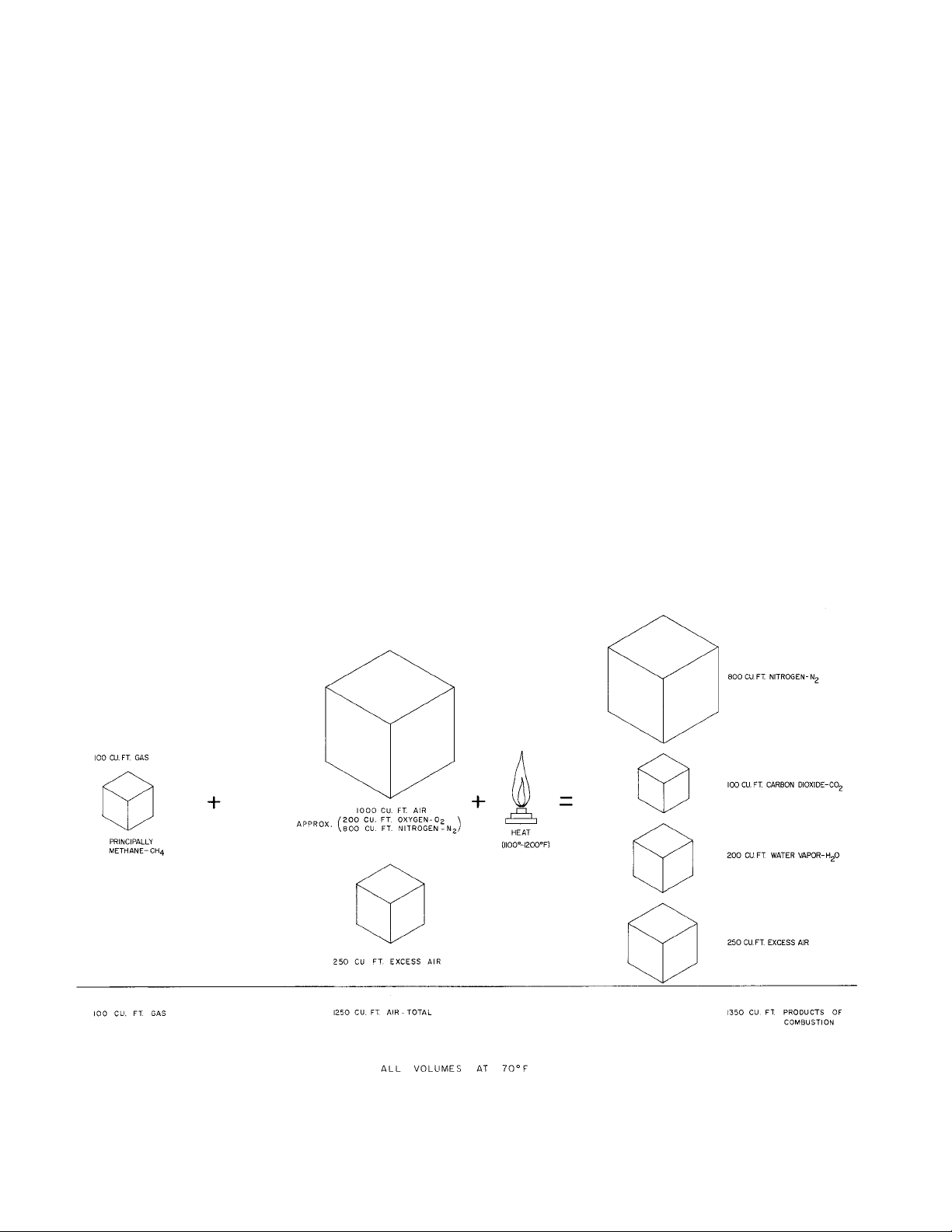
1.2 COMBUSTION – In order for combustion or burning
to take place three things are needed:
1) Fuel-in this case, natural gas or propane.
2) Oxygen-oxygen is obtained from the air which is
approximately 20% oxygen and approximately 80%
nitrogen. Nitrogen is inert and will not burn.
3) Heat-gas will not urn until its temperature is raised
to its ignition point, approximately 1100-1200°F. A
gas burning pilot (open ame) or electrical means
(spark) is used for the initial ignition after which
the ame itself provides the heat needed to sustain
combustion.
If any of the three are taken away, combustion cannot
take place.
Because the mixing of air and fuel is not 100% complete,
more air than is actually needed called excess air must
be supplied to the appliance in order for burning to be
complete. This is shown in Figure 1-1.
If the supply of fresh air is inadequate or is not contin-
ually replenished as it is used up, carbon monoxide (CO)
and Hydrogen (H2) as well as the products of combustion
shown in Fig. 1-1 may be produced. This is undesirable
since carbon monoxide is toxic and some-times lethal
even in small quantities.
In addition to the fresh air required for combustion,
fresh air is also required to dilute the ue products so
that the resultant ue gas temperature is reduced to what
is considered a safe level. Thus, a total of 16 cu. Ft. of
air may be required for each cu. ft. of gas burned, 12.5
cu. ft. for the combustion process and 3.5 cu. ft. for the
dilution process.
1.3 VENTILATION – Fresh air requirements for the heating
plant will vary with the space in which the plant is located
as described and illustrated in succeeding paragraphs.
Reference to free area of air inlets is made in the text
since louvers, grilles, or screens are sometimes used at or
in the inlet and these have a blocking effect. This must
be taken into consideration in order to obtain proper
quantities of fresh air. If the free areas of these devices
are not known, it may be assumed that wood louvers will
have 20-25% free area and metal louvers and grilles will
have 60-75% free area.
For installation in boiler rooms with ventilation air
provided from inside of building having adequate
inltration from outdoors, each opening shall have a free
area of not less than one (1) square inch per 1000 Btuh
of the total input rating of the heating plant and other
fuel burning appliance in the boiler room. See Figure
1-2.
For installation in boiler rooms with ventilation air
provided directly from outdoors, each opening shall have
a free area of not less than one (1) square inch per 4000
Btuh of the total input rating of the heating unit and other
fuel burning appliance in the boiler room. Each opening
should be equipped with a screen covering whose mesh
should not be less than ¼ inch and each opening should
be constructed so that they cannot be closed. See Figure
1-3.
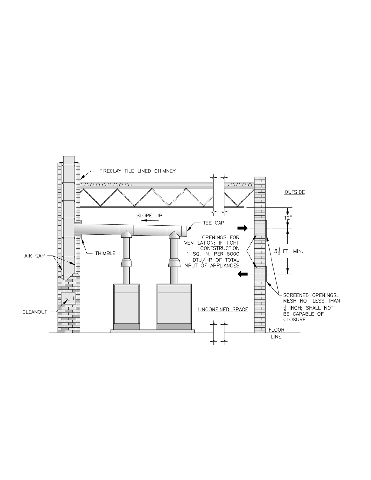
Normally, if the boiler is installed in an unconned space,
an adequate amount of ventilation air will be supplied by
natural inltration. If however, the unconned space is
of unusually tight construction, air from outdoors will be
needed. A permanent opening or openings with a total
free area of not less than one (1) square inch per 5000
Btuh of the total input rating of the heating plant and
other fuel burning appliances in the unconned space
is necessary. If ducts (minimum rectangular area of 3
square inches) are used, they must be the same crosssectional area as the free area of the opening to which
they connect. Screening to cover the openings to the
outside should not be smaller than ¼ inch mesh and
each opening should be constructed so that they cannot
be closed. See Figure 1-4.
Adequate combustion and ventilation air must be
provided to assure proper combustion.
The importance of adequate and proper ventilation
cannot be overemphasized. It must also be
understood that venting and ventilation must always
be considered together. They are both part of the
same system and must balance each other.
If exhaust fans are utilized such as for make-up
air, the make-up air should not be drawn from the
same space that is the source of combustion air for
the heating plant unless adequate provisions are
made to supply additional outside air so that the
space surrounding the heating unit is not under a
negative pressures (less than outdoor pressure).
Blowers should not be used to forcibly provide
ventilation unless controlled to a point where static
pressure in the space in which the heating plant is
located is equal to the outdoor pressure.
8
Page 9
(continued)
Excess pressure resulting from larger than
necessary volumes of fresh air will cause excessive
dilution of the ue products resulting in low ue
gas temperatures. If lowered below the dew point,
condensation of the moisture in the ue gases
will occur and, if continued over an extended
period of time, will corrode vents, drafthoods, heat
exchangers, and burners.
There are certain elements known as halogens
(uorine, chlorine, bromide, iodine and astatine)
which are utilized in many commercial products
(refrigerants, solvents, spray can propellant, etc.).
If these products must be used near the heating
plant, extra precaution must be taken to obtain
uncontaminated air from the outside, otherwise
severe corrosion will occur in the boiler and vent
system.
When an existing boiler is removed from a
common venting system, the common venting
system is likely to be too large for proper venting
of the appliances remaining connected to it.
1.4 VENTING – As pointed out before, venting is the
process of removing of the ue products. There
are basically two types of venting: atmospheric
(or gravity) and power venting. Further discussion
will be limited to atmospheric vent systems since
it is, by far, the most commonly used and the most
applicable to the Series 8H/8HE modular boilers. The
atmospheric system is composed of numerous parts
and it is necessary to understand the function and
operation of each part in order to properly design the
system.
Do not alter boiler draft hood or place any
obstruction or non-approved damper in the
breeching or vent system. Flue gas spillage can
occur. Unsafe boiler operation will occur.
1.4.1 DRAFTHOOD – The ue outlet of a heating appliance
such as the Series 8H/8HE module cannot be
connected directly to the vent system for the following
reasons:
a) The amount of air drawn thru the combustion
chamber would vary with the height of the vent
pipe. Hence, there would be little or no chance
of maintaining the same air ow rate thru the
appliance for the variety of installation conditions
which invariably are encountered.
b) There would be no way to compensate for variable
wind conditions encountered at the terminal of
the vent. If wind conditions created a negative
pressure at the vent terminal, this negative pressure
would tend to increase the ow thru the vent
system – this phenomena is referred to as updraft.
If the wind created a positive pressure at the
terminal, the ow through the vent system would
be retarded or reversed – this condition is referred
to as downdraft.
c) There would be no avenue of escape for the ue
gases in case the vent became blocked.
d) Flue gases, if undiluted, could reach temperatures
which would create a potential re hazard if the
ue gases were to strike ammable surfaces.
To overcome all of the deciencies outlined above,
an AGA listed vertical to vertical type of drafthood is
furnished with each Series 8H/8HE boiler, see insert
of Fig. 1-5. The inlet opening of the drafthood is
connected to the ue outlet of the boiler, and the exit
or outlet opening of the drafthood is connected to the
riser portion of the vent connector. The inlet and exit
diameter and the stem height of the drafthood are a
function of boiler size since they were determined
only after extensive testing and after certication by
the American Gas Association and by the Canadian
Gas Association. Therefore, THE DRAFTHOOD
MUST NOT BE ALTERED IN ANY MANNER.
1.4.2 VENT CONNECTOR – see Fig. 1-5. The vent
connector is that portion of the vent system which
connects the exit (outlet) of a drafthood of an
individual appliance to the manifold vent (breeching)
servicing two or more boilers. If there is a horizontal
run in the vent connector, this horizontal run is
known as a lateral. Since the vent connector may
enter the bottom or the side of the manifold vent,
the vent connector rise is the vertical distance from
the drafthood outlet to the lowest level at which
the connector enters the manifold. A slip joint or
drawband, as illustrated in Fig. 1-5, will facilitate
installation of connectors as well as replacement
of parts in that portion of the system should it ever
become necessary.
1.4.3 MANIFOLD AND COMMON VENTS – see Figs.
1-5, 1-6. A manifold vent or breeching is a horizontal
extension of the vertical common vent. The common
vent, which is sized to handle the total load when
all modules are operating, can be of masonry
construction, single-wall metal pipe, or type B Gas
Vent Pipe – consult local codes. A UL Listed vent
cap should be installed, if possible, at the exit of the
common vent to assure full vent capacity and freedom
from adverse wind effects.
Total vent height is the vertical distance between
the exit of the common vent and the exit or outlet
of the drafthood. Regardless of the calculated total
vent height required for capacity, all vents must be
correctly terminated a sufcient distance above the
roof surface and away from nearby obstructions,
see Figs. 1-5 and 1.6. This is to avoid adverse
9
Page 10
wind effects or pressure areas which may reduce
or impede vent ow. This does not imply that
terminations at these locations will assure proper
venting in every instance. Because winds uctuate
in velocity, direction, and turbulence, and because
these same winds impose varying pressures on the
entire structure, no simple method of analysis or
reduction to practice exists for this complex situation.
Manifold vents may be run horizontally or sloped
upwards toward the common vent. Slope should not
exceed ¼” per foot unless required otherwise by local
codes. Regardless, minimum vent connector rise as
determined for each appliance must be maintained.
Manifold vents may be of constant diameter (Fig. 1-5)
in which case they are of the same size as the common
vent or its equivalent. Manifolds may also be tapered
(Fig. 1-6) for the actual input to a particular section of
the manifold. Difference in operating characteristics
between properly sized constant diameter manifold
vents or tapered manifold vents are negligible and
choice is usually dictated by convenience and cost.
1.4.4 INDIVIDUAL VENTS – Economics thru the use
of smaller vent pipe and the elimination of ttings
could dictate the use of an individual vent system for
each module (see Fig. 1-7) rather than a combined
vent system. If the individual vents are of the proper
diameter and the total vent height is a minimum of
5 ft., the systems are self venting and more reliable
than a combined vent system since, in the latter, it is
impossible to anticipate all contingencies.
1.4.5 VENT AND CHIMNEY MATERIALS AND
CONSTRUCTION – The materials of construction for
vents and chimneys include single-wall metal, various
multi-wall air and mass insulated types as well as
masonry, which could be precast or site constructed.
In many instances, national or local codes will govern
what type may be used. Where choice is possible,
many advantages can be listed for the UL Listed
double wall metal type B vent:
1) warm up is faster with type B vents than vents
having greater mass
2) type B vents permit closer clearance to
combustible material than single wall metal vents
unless special precautions are taken with the latter
3) type B vents are less prone to condensation and
corrosion than single wall metal vents
4) type B vents are lightweight, easy to handle and
assemble
Manufacturer’s instructions relative to installation
of their product should be followed as long as they
comply with the National Fuel Gas Code and/or local
codes. Some items to consider are:
1) support of lateral runs so that vent pipe does not
sag
10
COMPLETE COMBUSTION OF NATURAL GAS
FIGURE 1-1
Page 11
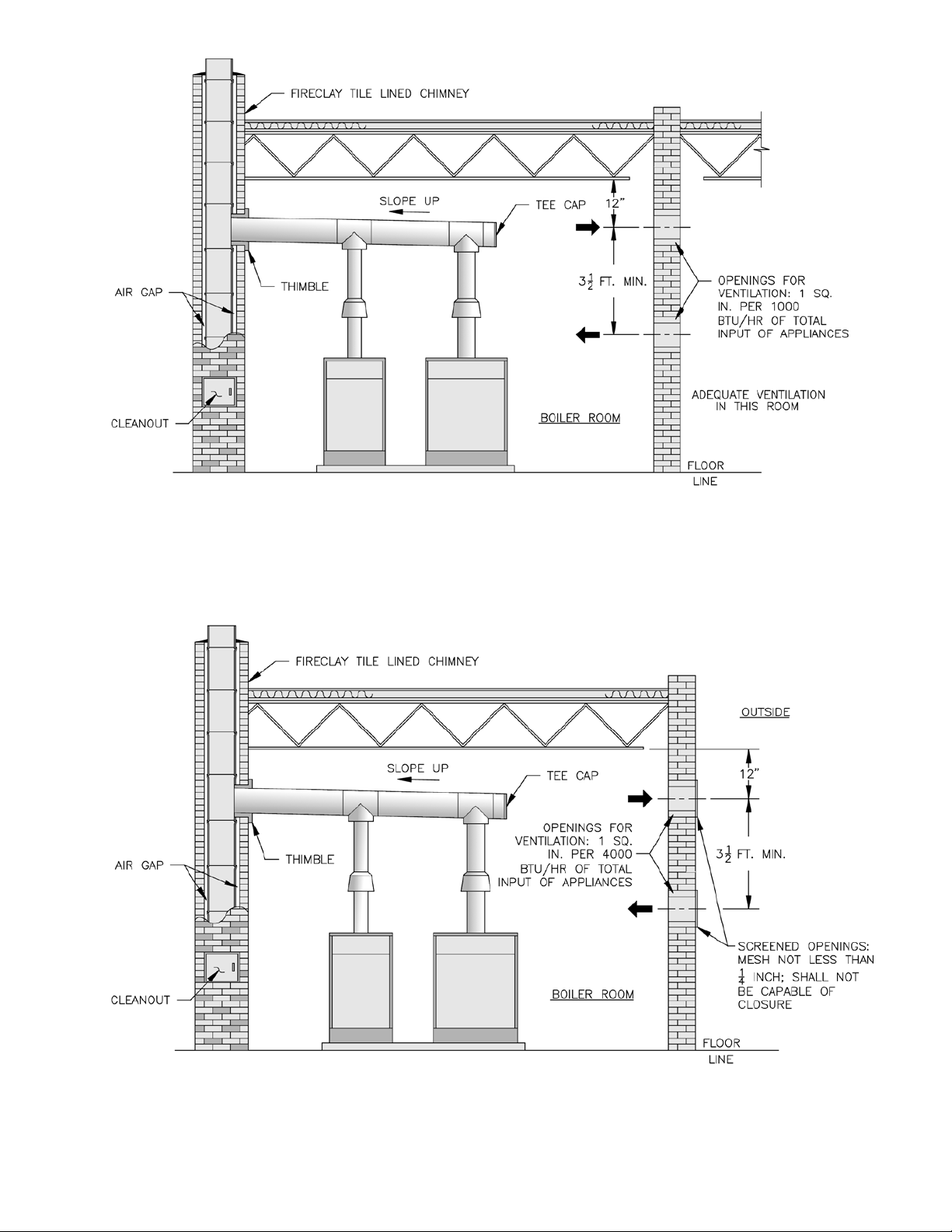
CONFINED SPACE, VENTILATION AIR PROVIDED
FROM INSIDE OF BUILDING
FIGURE 1-2
CONFINED SPACE, VENTILATION AIR PROVIDED
FROM OUTDOORS
FIGURE 1-3
11
Page 12
2) support of common vent where it passes thru a
ceiling or roof
3) clearances to combustible material – use of
thimbles
4) restops
5) ashing and storm collars
6) guying or bracing of common vent pipe above roof
7) securing and gas tightness of joints
8) lightning arrester if top of metal vent is one of the
highest points on the roof
9) proper termination of vent connection at masonry
chimney – vent should enter chimney at a point
above the extreme bottom of chimney – vent
should be ush with inside of chimney and sealed
(see Fig. 1-5)
10) never connect a gas vent to a chimney serving a
replace unless the replace has been permanently
sealed
11) never pass any portion of a vent system thru a
circulating air duct or plenum.
12
UNCONFINED SPACE—TIGHT CONSTRUCTION
VENTILATION AIR PROVIDED FROM OUTDOORS
FIGURE 1-4
Page 13
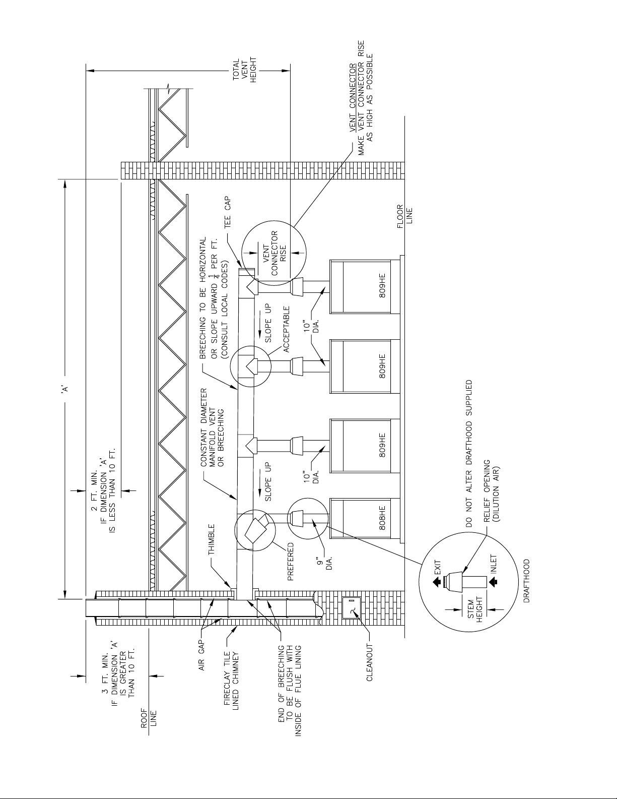
CONSTANT DIAMETER MANIFOLD VENT OR BREECHING
FIGURE 1-5
TWO THROUGH EIGHT MODULES
13
Page 14
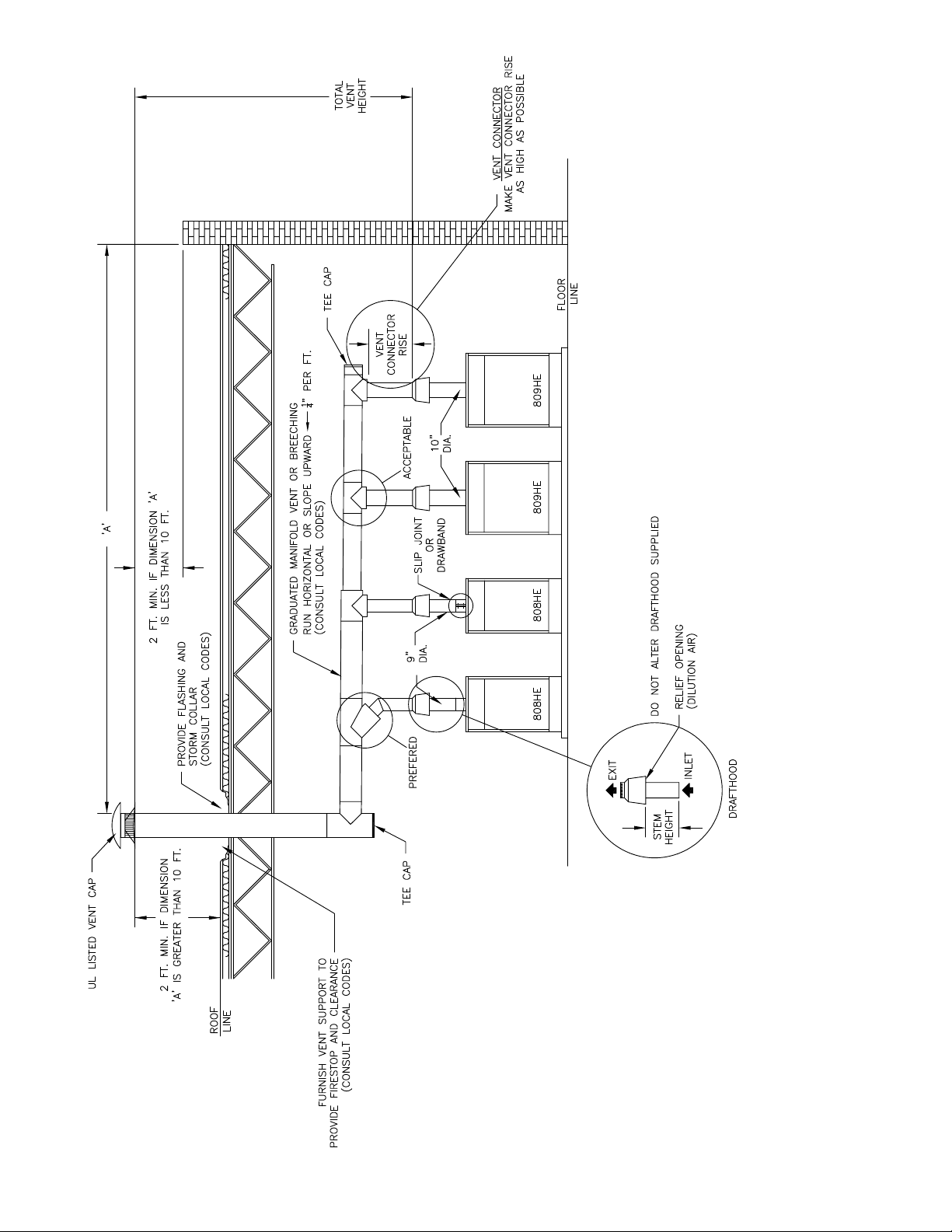
GRADUATED DIAMETER MANIFOLD VENT OR BREECHING
FIGURE 1-6
TWO THROUGH EIGHT MODULES
14
Page 15
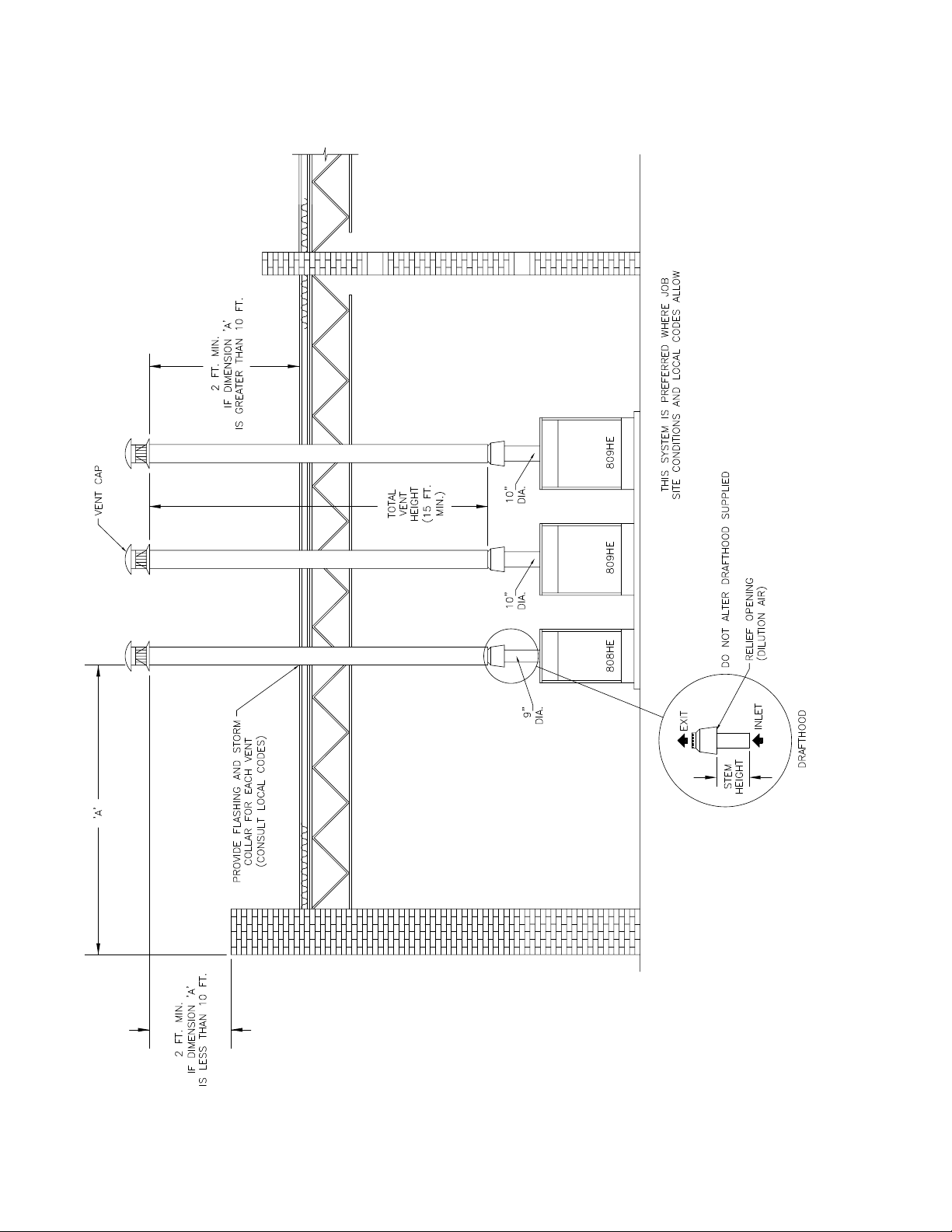
FIGURE 1-7
INDIVIDUAL VENTS
TWO THROUGH EIGHT MODULES
15
Page 16

SECTION 2.0 VENTS
Inspect existing chimney before installing boilers.
Failure to clean or replace perforated pipe or tile
lining will cause severe injury or death.
2.1 Vents, or breeching ducts, are generally less exible
in design location than are water pipes, gas pipes
or electrical lines. To avoid conicts for a given
location, design and layout the vents in this section
before proceeding to other sections of this manual.
2.2 Obtain a scaled drawing of the boiler room. Note the
oor size, ceiling height, exterior walls, and chimney
location, if provided.
2.3 Determine the input required to the system. It is
recommended that the heating load be determined by
an accurate calculation of the heat loss of the structure
using methods contained in the ASHRAE Guide. If
service water is to be added capacity as described in
paragraph 3.13 of this manual. The boiler capacity
so obtained is net rating to input. Record the input
required on the boiler room drawing.
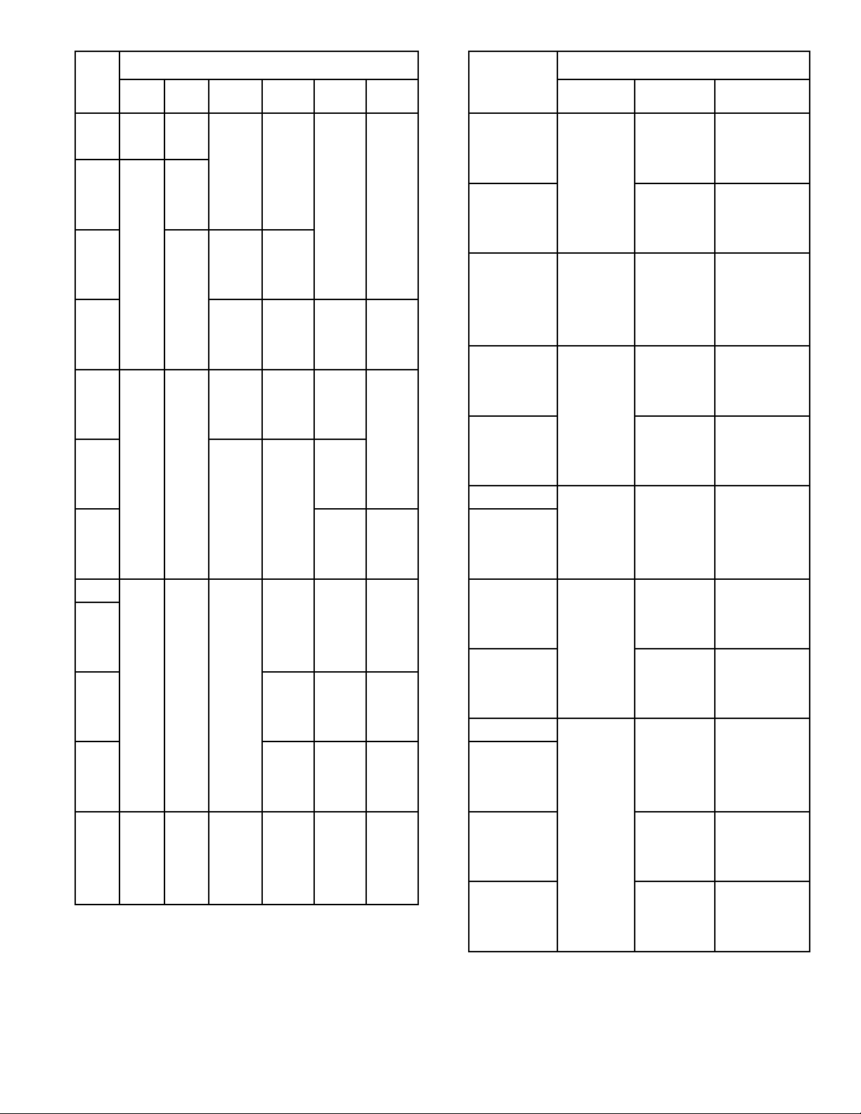
2.4 Using Figure 2-2 for the input found in 2.3 above, nd
the number of modules recommended. Those module
combinations shown represent the best selection for
lowest rst cost. Other combinations may be selected,
within the following guidelines:
1) Modules using a sequencing control system, such
as Tekmar described in Section 5.0, should not
vary by more than one size.
2) Modules using a combined vent system should not
vary by more than one size.
3) The combined vent sizing procedures in this
section are based on a maximum of eight modules
using a common vent system. If it is desired to
serve more than eight modules with a common
vent system, the specic requirements should
be referred to the BURNHAM COMMERCIAL
Application Engineering Department.
Refer to Figure 2-3 for individual module inputs.
2.4.1 Sketch on the boiler room drawing the approximate
location of the modules. Figures 2-4 thru 2-9 show
several layouts that can be used depending on the size
and shape of the boiler room and chimney location,
if provided. Refer to Figure 2-3 for dimensional data
on individual modules. Select the layout which best
ts the boiler room. Bear in mind that for combined
vent systems it is desirable to keep horizontal laterals
as short as possible. On a combined vent system for
which a xed chimney is provided, it is desirable to
place the rst module close to the chimney.
2.4.2 If the factory fabricated water manifolds are to be
used, 805H, 806H, and 807HE modules should be laid
out with 28½” module spacing and 808HE, 809HE,
and 810HE modules should be laid out with 40”
module spacing. If an 807HE and an 808HE module
are to be connected to a common manifold, use the
longer manifold with 40” spacing. Otherwise, any
module spacing that allows at least 1 inch jacket –tojacket spacing if acceptable, pending local or state
code requirements that may require greater module to
module spacing.
2.4.3 Refer to Figure 2-10 for minimum clearances around
modules to combustible materials and for service
access. CAUTION: Local re ordinances may be
more restrictive and should be complied with.
2.5 One of the serious errors made in layout of a boiler
room is the failure to provide sufcient ventilation
air. Insufcient ventilation air will cause incomplete
combustion, poor ignition, accumulation of soot in
the boiler, or the production of toxic gases. Many
service calls for dirty boilers, nuisance lock outs,
noisy ignition, or obnoxious odors are traceable to
insufcient ventilation air. Use Figure 2-11 at the
input desired to nd the recommended free area of the
ventilation opening required. Reference to Figures
1-2 thru 1-4 should be made in order to understand
the types of installations described in the headings
of Figure 2-11. Record the free ventilation area
required on the plans of the boiler room and sketch
the openings like those shown in gures 1-2 thru 1-4
respectively.
2.6 Individual vents as shown in Figure 1-7 are highly
recommended if the job site conditions allow.
Individual vents are particularly useful in boiler rooms
having a low ceiling height. Individual vents are
easy to design and in many cases result in the lowest
installed cost. They also are the most dependable in
operation and less susceptible to condensation than are
combined vents. To size individual vents, use Figure
2-12 with the vent height available, the lateral length,
size of module and type of vent pipe.
2.7 Combined vents will perform satisfactorily if strict
design procedures are followed. Referring to Figures
2-4 thru 2-9, note that a connector rise F of at least
one foot is required. A connector rise F of three feet
is desirable. Thus, to make the desired connector rise
and have space for the manifold vent, the minimum
boiler room ceiling height must be equal to:
32½” Module Height
+ ) Drafthood Height
+ F Minimum Connector Rise
+ CV Manifold Diameter
+ 6” Clearance
= Minimum Ceiling Height
If the minimum ceiling height above is not available,
common vents will not perform satisfactorily and
should not be used.
16
Page 17

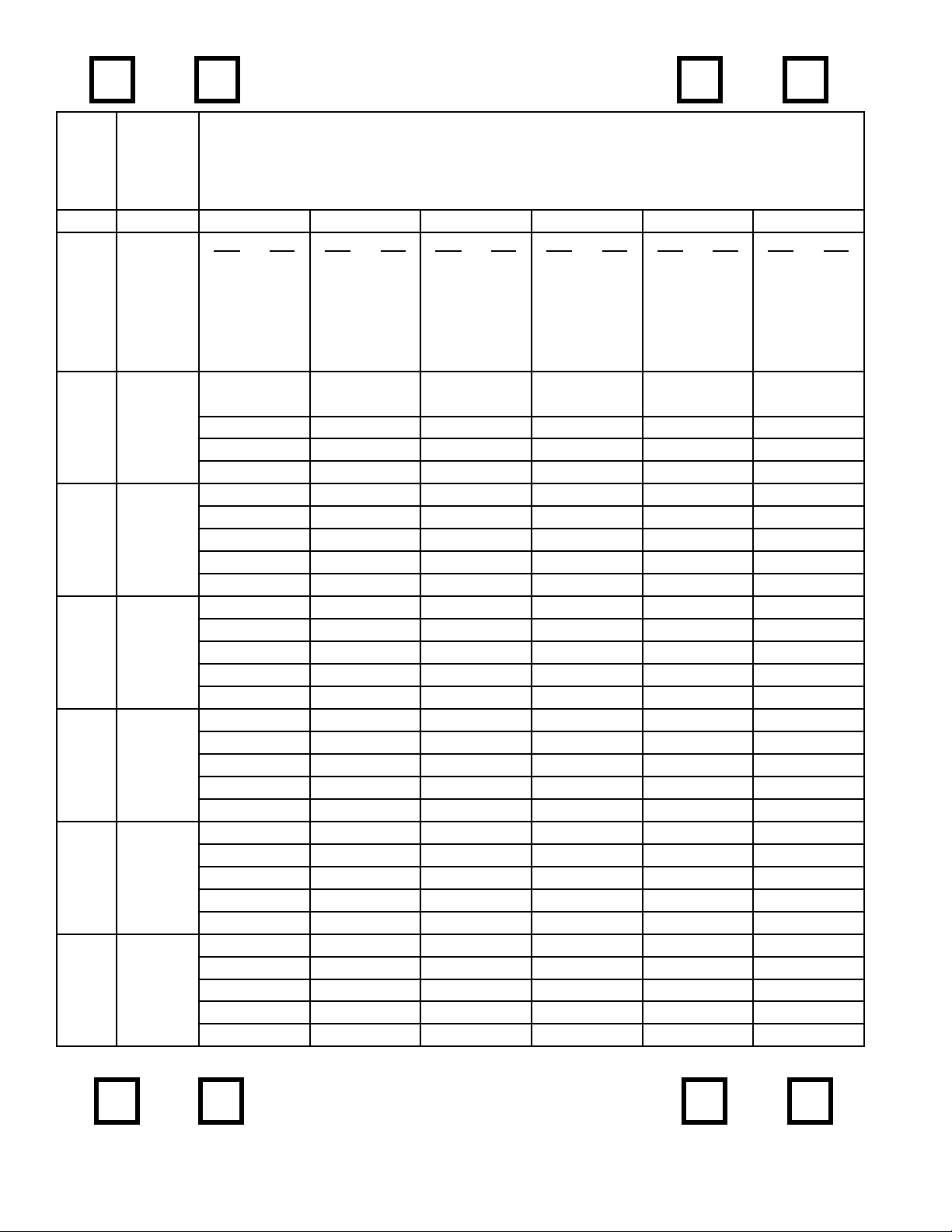
2.7.1 If the minimum ceiling height is available, proceed
to size the common vent CV in Figure 2-13. Enter
the left hand column at the desired total input and
move right to the column corresponding to your
H, least total vent height, and read the diameter of
the common vent. If more than one elbow is used,
increase CV by one pipe size for each elbow more
than one. Proceed to size the connector rise diameter
CN by entering Figure 2-14 at H available and move
right to the column headed F. On the line for available
connector rise move right to the CN columns headed
by the module sizes selected in 2.4 above. Read the
connector diameter(s). Record these sizes on the
plans of the boiler room.
2.7.2 If a tapered or graduated manifold vent is desired, use
the same procedures above for sizing the intermediate
manifold diameter but for the total input of the
modules served by intermediate tapered or graduated
manifold vent.
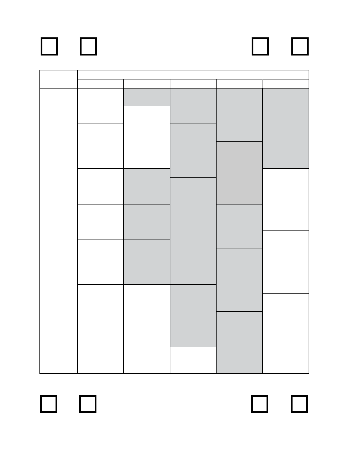
2.7.3 Within Figure 2-12 are several entries of NR.
This means that the combination involved is
not recommended. The most common reason
for a combination to be designated NR is that
condensation inside the vent pipe is likely to occur.
This is particularly true of single wall vent pipe.
Combinations outside the shaded area in Figure 2-13
are also not recommended for single wall vent pipe.
Additionally, single wall vent pipe should not be
used with ve or more modules because the dilution
from the unred modules plus the lower surface
temperature of single wall pipe makes condensation
and the resulting corrosion very likely.
2.8 If a masonry chimney is desired, the minimum cross
sectional area of the chimney is found in Figure 2-15
as a function of the vent diameter. Figure 2-16 shows
the area of standard chimney tiles by size.
2.9 The following is an example of the recommended
design procedures.
Example: A 3 story apartment house needs a total
boiler capacity including service water hating, of
1,849,500 Btu/Hr net rating. The boiler room is in
a one story added portion of the building, of noncombustible construction, similar to Figures 1-6 or 1-7
and is 20 feet long, 10 feet wide with a clear ceiling of
12 feet. No chimney is provided. Select and size the
vent system.
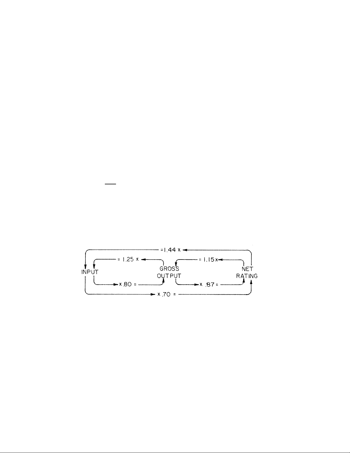
1) Refer to Figure 2-1 to convert net rating to input.
Input = 1,849,500 x 1.44 = 2,663,280 Btuh = 2,663
MBH.
2) From Figure 2-2 nd the closest recommended
module combination having an input of 2663
MBH. It is found that an input of 2710 MBH is
the closest size and is composed of ve 809HE and
one 808HE modules.
3) Sketch approximate module locations on the boiler
room plans using minimum clearances recommended in 2.4 above. In this case there is space to
lay-out the ve modules in line along one wall on
40” centers with ample service clearances, front,
rear, and sides, per Figure 2-10.
4) Determine the ventilation areas required from
gure 2-11. It is a conned space but outdoor air
is readily available through vents in the exterior
wall. Use the equation for Conned with Outdoor
Vent:
MBH Input = 2,710. = 677.5 sq. in.
4.0
of free ventilation area required.
5) Select the type of vent system – individual or
combined.
For an individual vent system use Figure 2-12 to
determine the vent size(s). In this example, the
height of drafthoods above the oor = 32½” +
33½” = 66” = 5½ feet. The least total vent height
is calculated from the drafthood up to the top of the
vent pipe which must be at least two feet above the
roof.
12 Ft. Ceiling Height
- 5½ Ft. Drafthood Height
+ 2 Ft. Ceiling Thickness
+ 2 Ft. Vent Extension
= 10½ Ft. total Vent Height, H
Enter Figure 2-12 at H = 10 Ft. and move right to
L = O Ft. Move right to 809HE column and nd
8” diameter for type B pipe and 10” for single
wall pipe. Continue to the right on the same line
to 809HE column and nd 9” diameter for type B
pipe and 10” for single wall pipe. Mark these sizes
on the drawing of the boiler room. If no more
than two 90° elbows are used in the system, no
corrections are necessary. The design is complete.
6) If a combined vent is desired such as in Figure 1-5,
use Figure 2-13 to nd the common vent size, CV.
Enter Figure 2-13 at 2710. MBH input. Move
right to the column H = 10 Ft. and nd common
vent diameter CV = 26” for type B pipe and single
wall is not recommended. Enter Figure 2-14 at H
= 10 Ft. and move right to F = 3 Ft. Move right
and nd connector diameter CN of 12” in the
809HE column and 12” in the 810HE column.
Calculate minimum ceiling height.
32½” Module Height
+ 33½” Drafthood Height, D
+ 36” Desired connector Rise, F
+ 26” Manifold Diameter, CV
+ 6” Clearance
= 11’2” Minimum Ceiling Height
A twelve foot clear ceiling height will work. With
only one elbow, no correction is necessary. The
design of a constant diameter manifold vent is
complete. Mark these vent and connector sizes on
the drawing of the boiler room.
17
Page 18
7) If a tapered or graduated manifold vent is desired,
such as in Figure 1-6 the horizontal and vertical
portion of the vent serving ve modules is also
complete with 6) above. However, to size the
manifold vent at an intermediate position such as
CV3 in Figure 2-4, use Figure 2-13 for the MBH
Input of the modules served by that position of the
manifold vent. The Input MBH of each module
can be determined from Figure 2-3. In this case
CV3 serves two modules having an input of
920 MBH. Enter gure 2-13 at an input of 920
MBH. Move right to H = 10 Ft. and nd CV3
= 14” diameter. Mark this vent diameter size on
the drawing of the boiler room. Thus a graduated
manifold vent design is complete. It is possible
with this procedure to reduce the manifold vent
size after each module. However, from a practical
standpoint, the cost of ttings may offset the lower
cost of smaller vent pipe.
2.10 All of the above procedure is based on data found
in the ASHRAE Guide, 1975 Equipment Volume,
Chapter 26. The basic chimney equation is expressed
as follows:
(di)² (∆PB)
I = 4.13 x 10
5
x M x (KTm)
0.5
where: I = Operating heat input, BTUH
di = Inside diameter of the common vent or
manifold vent
M = Mass ow input ratio, lb. of products per
1000 BTU of fuel burned. A value of 1.60 was
used based on 5.3% CO2 after dilution. An
additional 15% dilution was added for each
unred module.
∆P = Pressure difference or loss in the system
acting to cause ow, inches of water. Use
0.537 inches water per 100 Ft. of pipe.
B = Sea level barometer used —29.92” Hg
K = Resistance loss coefcients, dimensionless.
Tm = Temperature in vent system at average
conditions, °Fabs.
The serious Engineer should become familiar with the
above basic equation and the range of the variables that
may be encountered. The tables in Figures 2-12 thru
2-14 should not be extrapolated. If system conditions
do not fall within the limit of the tables, vent sizes must
be calculated using the chimney equation above as
described in the ASHRAE Guide.
18
RELATIONSHIP OF INPUT, GROSS OUTPUT, AND
NET RATING FOR SERIES 8H/8HE MODULES
FIGURE 2-1
Page 19
Total
Input
MBH
Recommended Number of Modules
805H 806H 807HE 808HE 809HE 810HE
Total Input
MBH
Recommended Number of Modules
808HE 809HE 810HE
504 2
567 1 1
630 2
655 1 1
680 2
750 1 1
820 2
870 1 1
920 2
965 1 1
1010 2
1090 2 1
1160 1 2
1230 3
1280 2 1
1330 1 2
1380 3
1425 2 1
1470 1 2
1515 3
1570 1 3
1640 3 1
1690 3 1
1740 2 2
1790 1 3
1840 4
1885 3 1
1930 2 2
1975 1 3
2020 4
2100 4 1
2150 3 2
2200 2 3
2250 1 4
2300 5
2345 4 1
2390 3 2
2435 2 3
2480 1 4
2525 5
2610 3 3
2660 2 4
2710 1 5
2760 6
2805 5 1
2850 4 2
2895 3 3
2940 2 4
2985 1 5
3030 6
3070 3 4
3170 1 6
3220 7
3265 6 1
3310 5 2
3355 4 3
3400 3 4
3475 2 5
3490 1 6
3535 7
3630 1 7
3680 8
3725 7 1
3770 6 2
3815 5 3
3860 4 4
3905 3 5
3850 2 6
3995 1 7
4040 8
FIGURE 2-2
19
Page 20
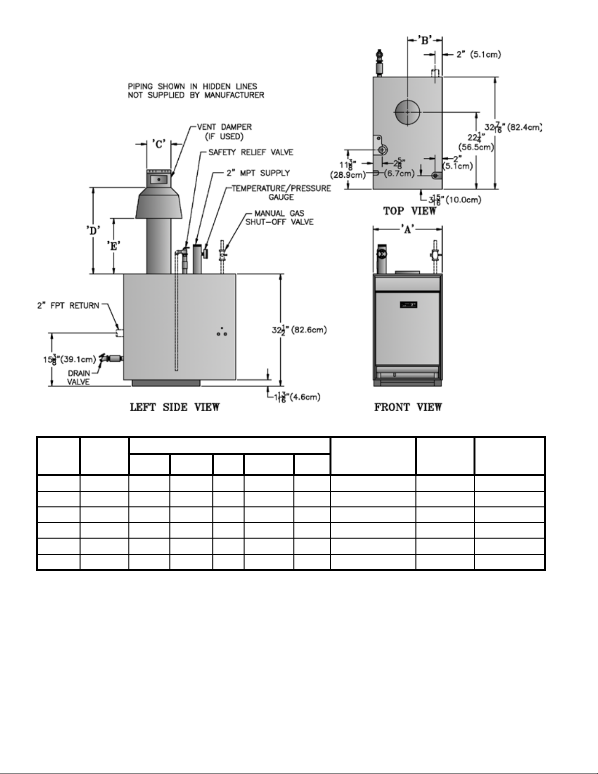
Boiler
Model
805H 252 20 10 7 24-13/16 16-1/8 7" dia. x 15 ft. 11.9 680
806H 315 23-3/4 11-7/8 8 27-13/16 18 8" dia. x 15 ft. 13.9 770
807HE 340 27-1/2 13-3/4 9 27-13/16 18 8" dia. x 15 ft
808HE 410 31-1/4 15-5/8 9 30-13/16 20 8" dia. x 15 ft 17.9 950
809HE 460 35 17-1/2 10 33-1/2 22 10" dia. x 15 ft 19.9 1040
810HE 505 38-3/4 19-3/8 10 33-1/2 22 10" dia. x 15 ft 21.9 1140
Input
(MBH)
(1) Specialbaserequiredforinstallationsoncombustibleooring;adds4-3/4"toboilerheight(oortojackettoppanelis37-1/4").
(2) Gas connection size: 1 NPT
(3) Maximum Allowable Working Pressure: 50 psi (Water Only)
(4) Items shown in hidden lines supplied by installer.
"A' "B" "C" "D" "E"
Dimensions (inch)
Recommended
Chimney Size
(Round)
.
Water
Content
(Gallons)
15.9 870
Weight (LB)
Approx.
Shipping
FIGURE 2-3
20
Page 21
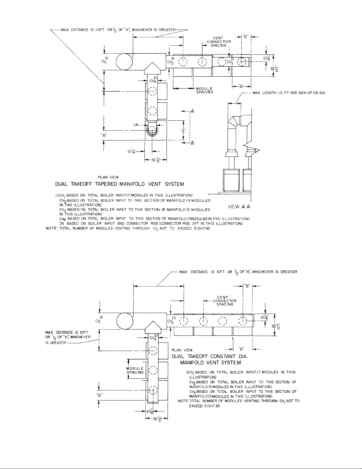
FIGURE 2-4
FIGURE 2-5
21
Page 22
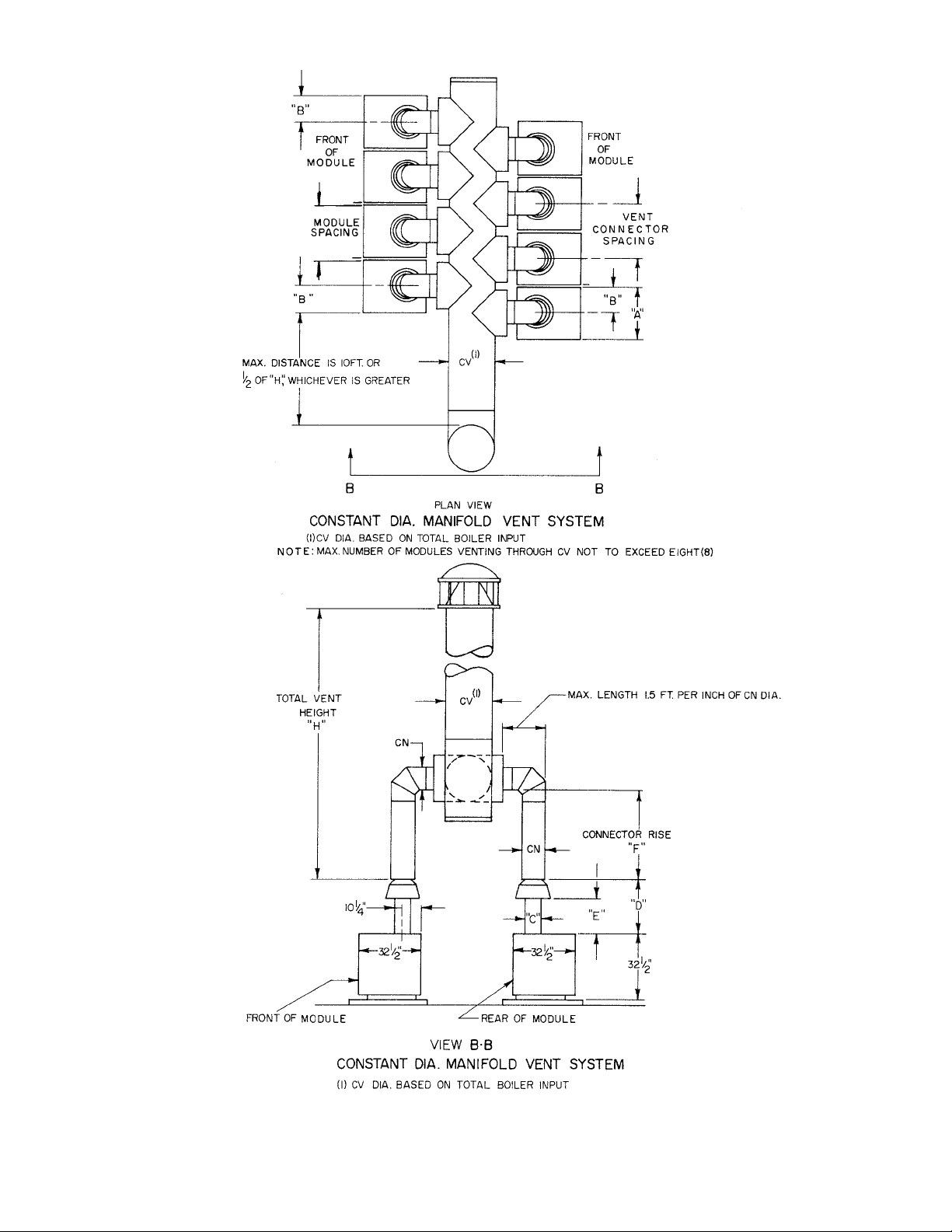
FIGURE 2-6
FIGURE 2-7
22
Page 23

FIGURE 2-8
FIGURE 2-9
23
Page 24

805-806-807
To Combustible
Construction
Recommended
For Servicing
808-809-810
To Combustible
Construction
Recommended
For Servicing
Drafthood &
Vent Connector
1 6" 2 36" 1 18" 1 6" 1 6" N/A N/A N/A
N/A 1 24" 1 24" 8 18" 24" 1 1" 26" 7 36"
1 6" 2 51½" 1 18" 1 6" 1 6" N/A N/A N/A
N/A 7 24" 7 24" 8 18" 24" 1 1" 26" 7 36"
N/A: Not Applicable, 1 USA & Canada, 2 USA Only: 18" in Canada, 5 or as necessitated by prefabricated water manifolds, 6
ConsultLocalCodesforminimumspacingofmultipleboilers,7USAOnly;48"inCanada,8USAOnly;24"inCanada.
Top of
Jacket
Front Side Rear
5 6 Side-
by-Side
6 Back-to-
Back
6 Front-to-
Front
MINIMUM INSTALLATION CLEARANCES AROUND MODULES
FIGURE 2-10
UnconnedSpacewith
Outdoor Vent
MBH Input
5.0
MBH Input refers to total input for all appliances in the boiler room.
ConnedSpacewith
Outdoor Vent
MBH Input
4.0
ConnedSpace
w/Inside Air
MBH Input
1.0
TOTAL FREE AREA OF VENTILATION OPENINGS, SQ. IN.
FIGURE 2-11
24
Page 25

1
Dia., In.
Metal Vent
Single Wall
Wall Vent
B, Double
Dia., In. Type
Dia., In.
Metal Vent
Single Wall
Wall Vent
B, Double
Dia., In. Type
1
INDIVIDUAL VENTS
DIAMETER OF VENTS SERVING A SINGLE MODULE (SEE FIGURE 1-7)
Dia., In.
Metal Vent
Single Wall
Wall Vent
B, Double
Dia., In. Type
Dia., In.
Metal Vent
Single Wall
Wall Vent
B, Double
Dia., In. Type
Dia., In.
Metal Vent
Single Wall
Wall Vent
B, Double
Dia., In. Type
10 9 10 9 10
FIGURE 2-12
DO NOT USE ANY PART OF THIS TABLE FOR COMBINED VENTS.
-
WARNING
1
Dia., In.
805H 806H 807HE 808HE 809HE 810HE
Dia., In. Type
Horizontal
Least Total
Metal Vent
Single Wall
Wall Vent
B, Double
Ft.
Lateral
Length L,
H, Ft.
Vent Height
righttosizeofmoduleandtypeofventpipe;(4)Pickoffminimumvent.SingleWallandTypeBVentDiametersarebasedonNFPA54.
5 7 7 7 8 8 8 8 10 8 10 9 10
2 7 7 7 8 7 8 8 10 8 10 9 10
5 7 8 8 8 8 10 9 10 9 10 9 10
2 7 7 7 8 8 8 8 10 9 10 9 10
5 7 8 8 10 8 10 9 10 10 10 10 12
2 7 8 8 10 8 10 9 10 10 10 10 10
0 7 8 8 10 8 10 9 10 9 10 10 12
12 NR NR NR NR NR NR NR NR NR NR NR NR
6
8
5 8 8 9 10 9 10 10 10 10 12 12 12
2 8 8 8 10 9 10 9 10 10 12 10 12
0 7 7 7 8 8 8 8 10 9 10 9 10
5 8 10 9 10 9 10 10 12 12 12 12 12
2 8 8 9 10 9 10 10 10 12 12 12 12
0 6 7 7 8 7 8 8 10 9 10 9 10
15 NR NR NR NR NR NR NR NR NR NR NR NR
10 NR 10 NR 10 NR 10 NR 12 NR 12 NR 12
10 8 8 8 10 9 10 9 10 10 12 10 12
10
0 6 7 7 8 7 8 8 8 8 10 8 10
20 NR NR NR NR NR NR NR NR NR NR NR NR
15 NR 8 NR 10 NR 10 NR 10 NR 12 NR 12
15 7 8 8 10 8 10 9 10 9 10 10 12
10 7 8 8 10 8 10 9 10 9 10 10 10
15
0 6 6 7 7 7 7 7 8 8 8 8 10
30 NR NR NR NR NR NR NR NR NR NR NR NR
20 NR 8 NR 10 NR 10 NR 10 NR 10 NR 12
15 7 8 8 8 8 10 8
10 7 8 7 8 8 8 8 10 9 10 9 10
20
30 NR NR NR NR NR NR NR NR NR NR NR NR
20 7 8 8 10 8 10 8 10 9 10 9 10
5 6 7 7 8 7 8 8 8 8 10 8 10
2 6 7 7 7 7 8 8 8 8 10 8 10
0 6 6 6 7 7 7 7 8 7 8 8 8
10 6 7 7 8 7 8 8 10 8 10 8 10
30
30 7 NR 7 NR 8 10 8 10 9 10 9 10
20 7 8 7 8 7 8 8 10 8 10 9 10
15 7 7 7 8 7 8 8 10 8 10 9 10
Tousethistable:(1)Enterlefthandcolumnatdesiredleasttotalventheight;(2)Movetotherighttosecondcolumnofthelinefordesiredhorizontallaterallength;(3)Movetothe
1
25
Page 26
2 8
-
CV - Diameter of Common Vent, Inches
2 8
-
Input MBH
504
567
630
655
680
750
820
870
920
965
1010
1090
1160
1230
1280
1330
1380
1425
1470
1515
1570
1640
1740
1790
1840
1885
1930
1975
2020
2100
2200
NOTE: Shaded Area indicates acceptable applications for Single Wall Metal Vent of the
same diameter as Type B vent. Otherwise, Single Wall Metal Vent is not recommended.
6 10 15 20 30
14
16
18 16
20 18
22 20
24 22 20
26 24 222150
H - Least Total Vent Height (Ft)
12
12
14 12
14
16
18
10
12
14
16
18
20
10
14
16
18
26
2 8
-
FIGURE 2-13
2 8
-
Page 27

2 8
-
2 8
-
Input MBH
2250
2300
2345
2390
2435
2480
2525
2610
2660
2710
2760
2805
2850
2895
2940
2985
3030
3070
3170
3220
3265
3310
3355
3400
3445
3490
3535
3630
3680
3725
3770
3815
3860
3905
3950
3995
4040 30
NOTE: Shaded Area indicates acceptable applications for Single Wall Metal Vent of the
same diameter as Type B vent. Otherwise, Single Wall Metal Vent is not recommended.
6 10 15 20 30
28
30
32
H - Least Total Vent Height (Ft)
26 24
28 26
30
28
22
24
26
28
20
22
24
26
2 8
-
FIGURE 2-13 (CONT')
2 8
-
27
Page 28
2 8
Least
Total
Vent
Height
Connector
H
6
8
10
15
20
30
40
-
Rise
F
805H 806H 807HE 808HE 809HE 820HE
DW SW DW SW DW SW DW SW DW SW DW SW
1 10 10 12 NR NR NR 12 NR NR NR NR NR
2 9 9 10 10 10 10 12 NR 12 NR 14 NR
3 9 9 10 9 10 10 12 NR NR NR 14 NR
4 NR NR NR NR NR NR NR NR 12 NR 12 NR
6 NR NR NR NR NR NR NR NR NR NR NR NR
1 10 10 12 NR 12 NR NR NR NR NR NR NR
2 9 9 10 10 10 10 12 NR 12 NR 12 NR
3 8 8 8 9 10 10 12 NR 12 NR 12 NR
4 NR NR NR NR 12 NR 12 NR 12 NR 12 NR
6 NR NR NR NR 12 NR 12 NR 12 NR NR NR
1 9 9 12 10 12 NR NR NR NR NR NR NR
2 9 9 10 10 10 10 12 NR 12 NR 12 NR
3 8 8 9 9 10 10 10 10 12 NR 12 NR
4 NR NR NR NR 12 NR 12 NR 12 NR 12 NR
6 NR NR NR NR 12 NR 12 NR 12 NR 12 NR
1 9 9 10 10 12 NR NR NR NR NR NR NR
2 8 9 9 9 10 10 12 NR 12 NR 12 NR
3 8 8 9 9 10 10 10 10 12 NR 12 NR
4 NR NR NR NR 12 NR 12 NR 12 NR 12 NR
6 NR NR NR NR 12 NR 12 NR 12 NR 12 NR
1 9 9 10 10 10 NR NR NR NR NR NR NR
2 8 8 9 9 10 10 12 NR 12 NR 12 NR
3 8 8 9 9 10 10 10 10 10 NR 12 NR
4 NR NR NR NR 12 NR 12 NR 12 NR 12 NR
6 NR NR NR NR 12 NR 12 NR 12 NR 12 NR
1 9 9 10 10 10 10 NR NR NR NR NR NR
2 8 8 9 9 9 9 12 10 12 NR 12 NR
3 8 8 8 9 9 9 10 10 10 NR 12 NR
4 NR NR NR NR NR NR 12 NR 12 NR 12 NR
6 NR NR NR NR NR NR 12 NR 12 NR 12 NR
1 9 9
2 8 8 9 9 9 9 10 10 12 NR 12 NR
3 7 8 9 8 9 9 10 10 12 NR 12 NR
4 NR NR NR NR NR NR 12 NR 12 NR 12 NR
6 NR NR NR NR NR NR 12 NR 12 NR 12 NR
9 10 10 10 NR NR NR NR NR NR
DW = Double Wall SW = Single Wall
2 8
-
28
2 8
-
FIGURE 2-14
2 8
-
Page 29

1 8
-
1 8
-
Individual Vent Dia.
From Figure 2-8
or Common Vent Dia.
CV - From Figure 2-9
6 34.
7 46.
8 60.
10 94.
12 136.
14 185.
16 241.
18 305.
20 377.
22 452.
Inside Area - Sq. In.
Tile Lined Masonry
Chimney
1 8
-
24 531.
26 616.
28 707.
30 804.
32 907.
FIGURE 2-15
1 8
-
29
Page 30
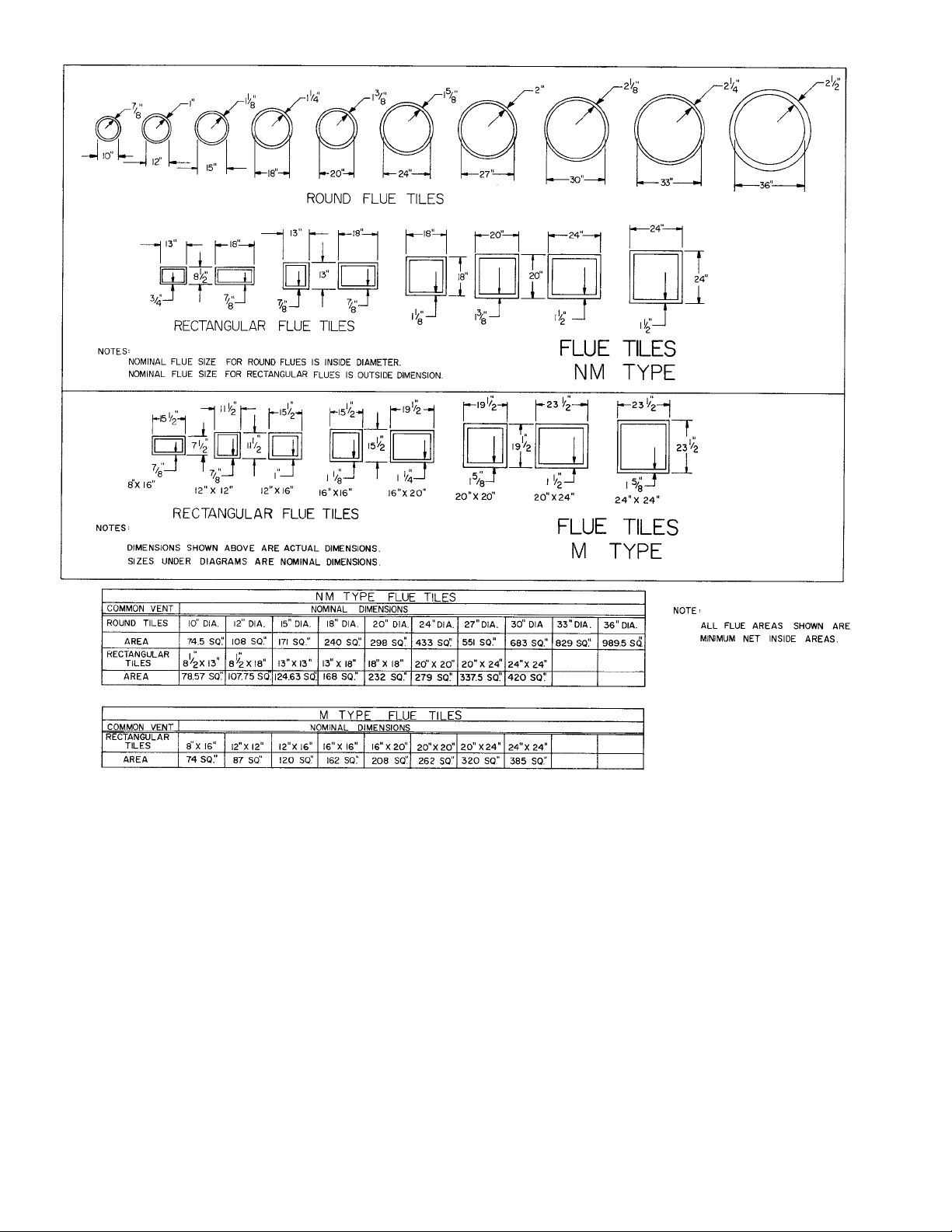
30
AREA OF TYPICAL MASONRY FLUE TILES
FIGURE 2-16
Page 31

SECTION 3.0 WATER PIPING
Burnham Commercial recommends maintaining temperature differential (drop) across the system at
40°F or less and return water temperature at minimum of 135°F.
CONTINUED BOILER OPERATION FOR PROLONGED PERIODS OF TIME UNDER CONDITIONS WHEN
TEMPERATURE DIFFERENTIAL ACROSS THE SYSTEM EXCEEDS 40°F AND/OR RETURN WATER
TEMPERATURE STAYS BELOW 135°F, MAY RESULT IN PREMATURE BOILER FAILURE DUE TO FLUE
GAS CONDENSATION AND/OR THERMAL SHOCK.
IF THE ABOVE CONDITIONS EXIST, TO PROTECT A BOILER FROM SUSTAINED FLUE GAS CONDENSATION
AND/OR THERMAL SHOCK, THE ABOVE-RECOMMENDED TEMPERATURES MAY BE MAINTAINED BY
EMPLOYING COMMON INDUSTRY-ACCEPTED MIXING METHODS TO PROVIDE BOILER PROTECTION.
Some common methods are boiler by-pass piping, blend pumps, primary secondary piping with a bypass, mixing valves and/or variable speed injection pumps.
Recommended Water Quality Requirements
Pressure relief valve discharge piping must be
piped such that the potential of severe burns
is eliminated. DO NOT pipe in any area where
freezing could occur. DO NOT install any shut off
valves, plugs or caps. Consult Local Codes for
proper discharge piping arrangement.
3.1 Breeching ducts are generally less exible in design
location than are water pipes. To avoid conicts for a
given location, design and layout the breeching ducts
before proceeding with water piping in this section.
3.1.1 The purpose of the Section 3.0 is to recommend
piping systems and accessories that can be used with
Series 8H/8HE Modular Gas Boilers. Although
recommended design procedures are presented, the
nal sizing of mains, pumps and compression tank
must be left to the designer of the total system because
only that designer has available the requirements and
capacities of the connected system.
3.1.2 Please consider the serviceman who must periodically
clean and adjust the boilers and repair accessories.
Do not block passageways with piping. Do not block
access panels on the boiler jackets.
3.2 MANIFOLDS—Selection of the proper manifolds is
important to the success of the modular concept. One
of the prime reasons for using modular boilers instead
of a single large boiler is to improve the seasonal fuel
efciency. Boiler losses are highest when the burner
is off and the boiler is still warm. Thus, if one small
module can carry the heating load during mild outdoor
weather by nearly continuous ring, a signicant loss
can be prevented and greater utilization of fuel can
be made. However, poor selection of manifolding
can wipe out part or all of the potential fuel savings
of the modular system. Some provision should be
made to prevent water from owing through any
module when it is not being red. When warm
system water is allowed to ow through any unred
module, heat is being wasted by convection through
the chimney and jacket of that unred module. For
pH: 8.3 - 10.5
TDS: < 3500 ppm
Total alkalinity ppm as CaCO
: < 1200
3
Total copper ppm: < .05
Oily matter ppm: < -1
Total harness ppm: < -3
Chlorides: < 50 ppm
example, on an eight module system red by an eight
step sequencer, only one module may be required
to meet the connected load demand on a day that
is 55°F outdoors. That would be a highly efcient
operation. However, if the system water is allowed
to ow through the other seven modules, they too are
kept warm and the total jacket and ue losses of the
eight modules may be as great as that of a single large
boiler. Thus, intended benet is lost.
3.2.1 Figure 3-1 shows a typical parallel pumping system.
Parallel pumping of modules does not prevent ow
through unred modules as commonly installed.
Thus, parallel pumping is not desirable unless a
motorized valve is used on the supply pipe from each
module and controlled to open only when that module
is red. With motorized valves, the owner may nd
objectionable noise from high velocity water ow
under light loads when the entire ow of the system
pump is directed through only one module of the
group.
3.2.2 By contrast, primary-secondary pumping provides
positive ow through each module only when that
module is red. Figure 3-2 shows such a system.
The piping is simple and uses only a single header
made up of fabricated steel manifolds available as
optional equipment. By keeping the head above
the top of the modules as shown in Figure 3-2, any
gravity circulation from header to unred modules
is prevented. Flow through each red module is
balanced as a result of having its own secondary
circulator.
31
Page 32

3.2.3 Primary-secondary pumping is preferred as it does
accomplish the desired fuel economy. To get the
same economy from parallel pumping it is necessary
to install some mechanism which will prevent ow
through unred modules as well as to install separate
supply and return headers. Thus, the total installed
cost of primary-secondary pumping may not be more
than that of a properly controlled parallel pumping
system.
3.2.4 If after careful consideration, the system designer
decides to use parallel pumping, a system using
reverse return headers as shown in Figure 3-1
is recommended. Direct return headers are not
recommended because direct returns are inherently
unbalanced and may prevent some modules from
delivering their rated capacities.
3.2.5 Optional fabricated manifolds are available as
a convenience to the installer and are highly
recommended with four or more modules.
3.2.5.1 Factory fabricated manifolds are lightweight and
quite forgiving of minor piping misalignments
common to multiple boiler installations. Each end
of the 4” manifold is ready for connection to another
manifold section or to the eld piping by means
of: 1. optional self-restrained pipe couplings,
or 2. eld roll-grooving for use of groove style
couplings. One lateral connection on each manifold
is threaded and intended to be made-up rst to
positively locate the manifold during its installation.
The other lateral connections on each manifold are
longer also threaded for those installations where
threaded ttings, such as unions, are desired, but it
is recommended that these longer threaded laterals
be cut off to yield plain ends for applying the same
style couplings as on the 4” ends.
3.2.5.2 The lateral connections on the factory fabricated
manifolds for use with 805H, 806H, and 807HE
modules are 1½” schedule 40, equally spaced on
28½” centers. The lateral connections on the factory
fabricated manifolds for use with 808HE, 809HE,
and 810HE modules are 2” schedule 40, equally
spaced on 40” centers. If an 807HE and an 808HE
module are to be connected to a common manifold,
use the longer manifold with 40” spacing.
3.2.5.3 Manifolds are available to serve two or three
modules. Two-module manifolds have two return
and two supply lateral connections, three-module
manifolds have three of each.
3.2.5.4 The manifolds are adaptable to parallel pumping
applications by capping half of the lateral
connections and using two manifolds: one for
supply and one for return. Refer to Figure 3-1.
3.2.5.5 A fundamental advantage of primary-secondary
pumping over parallel pumping is that water
temperature rise and ow rate thru each module
in a primary-secondary system is independent of
the system temperature drop and ow rate. Hence,
module piping to and from the manifold and
the module circulators on a primary-secondary
application may be based on a higher temperature
rise thru the module, say 30° or 40°F, and downsized
from the lateral connections. The module piping,
valves, and circulator for primary-secondary
pumping may be sized from the data in Figure 3-4.
3.2.5.6 For parallel pumping applications module piping
should equal the lateral connection sizes. Refer to
Figure 3-4 for module ow rates and pressure drop.
3.2.5.7 The maximum ow capacity of the factory fabricated
manifold is 265.GPM. If the system is based on a
20°F ∆T, these manifolds could serve modules with
a total input of 3400.MBH. If the system is based
on ad 30°F ∆T, these manifolds could serve modules
with a total input of up to 5100.MBH.
3.2.5.8 If the optional ex couplings shown in Figures 3-1
through 3-3 are to be used, they should be installed
according to the instructions in section 3.16.
3.2.5.9 If groove style couplings are to be used, they should
be installed according to the instructions in section
3.17.
3.2.6 On fewer than four modules, the designer may elect
to use commercial schedule 40 pipe and ttings of
a smaller size than the 4” pipe size of the fabricated
manifolds. Refer to 3.4.1 for the procedure used to
size a eld fabricated manifold. It should be noted
that in the case of primary-secondary pumping the
return line to each module should not be down stream
of the supply line from that same module to avoid
short circuiting of heated water within that module.
3.2.7 On a scaled drawing of the boiler room, layout the
selected water manifolds and mains.
3.3 STOP VALVES—Another prime reason for using
modular boilers is that of servicing without shutting
down the entire system. Any individual module
can be shut down for cleaning or repairs without
interrupting the operation of the remaining modules.
This is true of electrical components and the gas
components because most codes require a service shut
off at each module. A mistake is often made by not
installing water stop valves at the headers for each
module. By installing stop valves at the headers for
each module it becomes easy to perform repairs to
the water side of the module, such as leaky ttings,
control wells, and pumps. Without stop valves
each such service call results in the aggravation of a
system shut down. In addition, it takes time for the
serviceman to drain before the repairs and then rell
and vent the system after the repairs. That additional
service time may cost the owner more over the life
of the system than the cost of the stop valves at the
time of installation. Finally, the use of water side
stop valves on each module is required by some codes
in order to exclude the header and inter-connecting
water piping from consideration as an integral part of
a boiler. Stop valves are recommended as shown in
Figures 3-1 through 3-3.
32
Page 33

3.4 TEMPERATURE DROP—Selection of temperature
drop has received attention in recent years as a means
of reducing piping or pumping costs. Over several
previous decades the 20°F water temperature drop had
been standard for the hydronics industry. Recently,
temperature drops of 30°F, 40°F and even 50°F have
been used successfully when the distribution system
and terminal units are properly sized for these larger
temperature drops. In new construction it is advisable
to consider the savings in materials that can be made
by designing with a temperature drop larger than 20°F.
3.4.1 Figure 3-5 is a typical friction-velocity-ow diagram
used by most designers of large systems. The lower
scale, Heat Conveyed, is based on a 20°F temperature
drop. However, the ow rate in gpm is shown on
the upper scale, and can be used to size pipe at other
temperature drops by converting heat conveyed to
ow rate in gpm.
Example: Find the pipe size required to convey
1,000,000 Btuh in iron pipe at a friction loss of 500
mill inches/ft. and temperature drops of 20°F, 30°F
or 40°F.
Solution: The gpm ow rate for 1,000,000 Btuh is
found by dividing:
1,000,000 by (500 x 20) = 100 gpm for 20° drop
1,000,000 by (500 x 30) = 66.7 gpm for 30° drop
1,000,000 by (500 x 40) = 50 gpm or 40° drop
Enter Figure 3-5 on the horizontal line for 500 mill
inches per ft. and read across to the right to the
vertical lines for 100 gpm, 66.7 gpm and 50 gpm.
On the slanted lines read the corresponding pipe
sizes (use the larger if between two pipe sizes)
100 gpm = 3” Pipe
66.7 gpm = 2½” Pipe
50 gpm = 2½” Pipe
Figure 3-6 can be used in a similar manner for
copper pipe.
3.4.2 The size of the terminal units (baseboard, convectors,
fan coils, etc.) must be adjusted according to the
actual temperature of water owing in those units. In
general, the rst terminal unit on a circuit will receive
hotter than average water and should be undersized,
and the last terminal unit will receive cooler than
average water and should be oversized. The designer
should consult a sizing procedure such as that
contained in the ASHRAE Guide or I=B=R Guide
#250.
3.4.3 It should be noted that the selection of system
temperature drop has no effect on the sizing of the
boiler.
3.4.4 On remodeling jobs it is generally too expensive to
modify the terminal units for temperature drops other
than that used by the original system designer. It
is not “safe” to assume that the original design was
based on 20°F drop and thus the owner’s records
should be consulted.
3.5 MAIN PIPING—Selection of Main Size and the
system pump must go together. The system designer
can select the pump and size the pipe accordingly,
but more often the best economics of pipe and pump
causes the system designer to select the minimum
pipe size based on a maximum pressure drop and
then select a pump(s) to meet ow and pressure drop
requirements of the total system. It is recommended
that pipe sizes be selected in the unshaded portions of
Figure 3-5 or 3-6. The minimum pipe size will occur
on or close to the upper limit of the unshaded areas.
Example: Find the minimum main size and
corresponding friction for three 808HE modules using
iron pipe and a 20°F temperature drop.
Solution:
1) The output of three 808HE modules is 3 x 410 x
.80 = 984 MBH. Refer to Figure 2-3 for module
input and Figure 2-1 for input to output multiplier.
2) Enter Figure 3-5 on the lower horizontal scale at
984 MBH and move vertically to the upper limit of
the unshaded area.
3) On the lines that slant upward to the right, read the
pipe size. In this case, the pipe size is greater than
2½” but less than 3”. Select the larger of 3”.
4) From the point in 2) above move down vertically
to the 3” pipe line and horizontally to the left hand
scale. Pick off 300 mill inches per foot friction.
3.5.1 In calculating the total equivalent length of pipe it
is necessary to consider the additional resistance of
elbows. Figure 3-7 shows the equivalent lengths.
The total equivalent length of pipe in a circuit is the
measured length plus the equivalent length of all
elbows in that circuit. The total equivalent length
of the longest circuit in the system is useful in
determining the head requirement of the system pump.
3.6 COMPRESSION TANK—Selection of the
compression tank must be based on the following
items:
a) volume of water in the system
b) initial ll pressure of the system
c) maximum operating pressure of the system
d) maximum operating temperature of the
system
3.6.1 It is necessary to calculate the volume of water
contained in the total system including piping,
modules and terminal units. Figure 3-8 can be used
to determine the volume of the piping by measuring
the length of each size of pipe and multiplying by the
appropriate factor from Figure 3-8.
Example: Find the water volume in the piping of a
system having 40’ of 3” pipe, 72’ of 2” pipe, and 52’
of 1¼” pipe.
Solution: From Figure 3-8 obtain the gallons/ft.
from each size of pipe and multiply by the length of
that size of pipe.
1¼” Copper = .065 gal/ft x 52 Ft = 3.4 Gal.
+ 2” Copper = .161 gal/ft x 72 Ft = 11.6 Gal.
+ 3” Copper = .357 gal/ft x 40 Ft = 14.3 Gal.
Total volume in piping = 29.3 Gal.
33
Page 34

3.6.1.1 Use Figure 3-13 to calculate the volume of the
modules.
Example: Find the volume of water in four 806H
modules.
Solution: From Figure 3-13 nd that the water
volume of one 806H is 13.9 gallons and multiply by
the number of modules:
13.9 x 4 = 55.6 gallons in the modules.
3.6.1.2 The water side of terminal units must be known in
order to determine their volume. Tubular units such
as baseboard, commercial nned tube, convectors
and fan coils can be computed by knowing the
length and size of the tubes.
Example: Find the water volume in 528 ft. of 1¼”
copper dual tiered commercial nned tube.
Solution: From Figure 3-8 obtain the value of .065
gal/ft. for 1¼” copper and multiply by 528 ft. and by
2 tiers:
0.65 gal/ft x 528 ft x 2 tiers = 68.6 Gallons in the
Finned Tube.
3.6.1.3 From the above examples the total volume of the
system can be added:
Volume of piping = 29.3 Gal.
+ Volume of modules = 55.6 Gal.
+ Volume of Finned Tube = 68.6 Gal.
Total Volume of System = 153.5 Gal.
3.6.2 Conventional compression tanks can be sized by using
Figures 3-9 and 3-10. Enter Figure 3-9 in the left
hand column at the water volume of the system, move
across to the right to the maximum water temperature
of the system and read the uncorrected tank size.
To nd the correction factor, enter Figure 3-10 in the
left hand column of the initial ll pressure and move
across to the right to column for the system pressure
increase and read the tank correction factor. Multiply
the uncorrected tank size by the correction factor to
nd the nal tank size.
Example: Find the conventional compression tank
size for a system having a water volume of 153.5
gallons, a design water temperature of 240°F, a 50 psi
relief valve and a system height of 30 Ft.
Solution:
1) Enter Figure 3-9 in the left hand column and move
down to 200 gallons (which is the next largest
value to 153.5 gallons). Read across to the column
for 240 design water temperature and read 38
gallons uncorrected tank size.
2) Find the initial ll pressure by multiplying the
system height by 0.433:
30 x 0.433 = 13 psi
3) Enter Figure 3-10 in the left hand column and
move down to 12 psi ll pressure (closest to 13
psi). Move across to the column headed 40 psi
pressure increase (closest column to 40 psi minus
13 psi) and read a correction factor of 0.63
4) Multiply 0.63 x 38 Gal. = 24 gallons corrected tank
size.
5) Select a conventional compression tank size of at
least 24 gallons. In some cases, greater accuracy
may be obtained by interpolation in Figures 3-9
and 3-10.
3.6.3 Diaphragm type compression tanks can be sized by
using Figures 3-11 and 3-12. Find the expansion
factor for water at the design water temperature from
Figure 3-11. Multiply that expansion factor by the
volume of the system to obtain the acceptance volume
of the compression tank.
Find the tank volume by dividing the acceptance
volume by the acceptance factor from Figure 3-12.
Example: nd the diaphragm type tank size for the
same system as in 3.6.2 above.
Solution:
1) From Figure 3-11 at 240°F design temperature read
an expansion factor of .0518.
2) Multiply the system volume by the expansion
factor:
Acceptance volume = 153.5 Gal x .0518 = 8
gallons
3) Enter gure 3-12 at a ll pressure of 13 psi and
a nal pressure of 50 psi and read the acceptance
factor of 0.58.
4) Tank volume = 8 gallons ‘ 0.58 = 14 gallons
5) Select a diaphragm type tank having a minimum
acceptance volume of 8 gallons and a tank volume
of at least 14 gallons.
3.7 LOW WATER CUTOFF—On each modular installation at least one low water cutoff is required. If,
as recommended in 3.3, modules are installed with
shutoff valves in their respective supply and return
piping to the manifold then each module will require a
dedicated LWCO. Otherwise, a system LWCO will be
required.
3.7.1 If a system LWCO is to be used, such as shown in
Figure 3-1 or 3-2, it must be installed on the return
main at an elevation higher than the modules and
ll valve. The pipes connecting from the main to
the system LWCO must be teed into the return main
using the shortest possible 1” pipe and fewest ttings.
See Figure 3-1 or 3-2. Do not install valves between
the return main and the system LWCO. If for any
reason, the elevation of a module is different from
another module in the group, the system LWCO must
be installed above the module having the highest
elevation.
3.7.2 If dedicated LWCO’s are to be used they must be
installed between each module and its respective
shutoff valve and at an elevation higher than the
module and its ll valve. A probe style LWCO
is available as an option and its recommended
installation location is in the module’s supply riser
to the manifold as depicted in Figures 3-2 and 3-3.
Do not install any valve between the module and its
respective LWCO.
34
Page 35

3.8 RELIEF VALVE—Each Series 8H/8HE module
is supplied with its own pressure relief valve. No
additional relief valves need be installed on the
manifolds. If domestic water heating is added to
a module, it is recommended that a relief valve be
installed as shown in Figure 3-14.
3.9 LIMIT CONTROL—Each Series 8H/8HE module
is supplied with its own high limit control. To meet
ASME requirements, a second operating control must
be placed in the supply header downstream of the last
module but upstream of any valve on the supply main.
The size and type of control well will depend on the
control system selected in Section 5.0. Note: The
local jurisdiction may require that the high limit on the
module be of the manual reset type.
3.10 PRESSURE & TEMPERATURE GAUGE—Each
Series 8H/8HE module is supplied with its own
Tridicator so that the performance of each module can
be observed without installation of additional gauges.
3.11 FILL VALVE—An automatic ll valve is
recommended to maintain the minimum pressure in
the system at the ll pressure required by the height of
the piping system.
3.12 SYSTEM CIRCULATOR—To avoid placing the
head pressure of the system circulator on the boiler
and compression tank, the system circulator should be
installed such that it pumps away from the boiler and
compression tank. See Figures 3-1 and 3-2.
3.13 DOMESTIC WATER HEATING—An external water
heater may be added to any module on either primarysecondary or parallel circulation system. If heavy
water heating loads are anticipated an additional
module(s) may be added to the water heating circuit.
Refer to Figure 3-14 for recommended module water
piping for domestic water heating, with parallel
piping. Refer to Figure 3-3 for recommended pipng
when using an Alliance Indirect hot water tank with
Primary Secondary Piping.
3.13.1 Water heater size may be determined in the
following manner:
1) From Figure 3-15, nd the appropriate factor for
each xture in the building and add them together
to nd the total xture units.
2) From Figure 3-16, convert the xture units to hot
water capacity in gallons per minute based on 40140°F temperature rise.
3) Select water heater based on gallons per minute
from 2) above.
3.13.2 The addition of water heating may not necessarily
add to the size of the modules. Since the maximum
space heating lead and the maximum water heating
load rarely occur at the same time, only a portion of
the water heating load is added to the space heating
load to size the modules as follows:
1) Calculate the water heating load in Btuh:
__________gpm x 8.33 Lb/Gal x 60 Min/Hr x 100
∆T = ___________Btuh
2) Calculate ratio = Water Heating Load
Space Heating Load
3) From Figure 3-17, using the ratio found in 2), nd
factor for sizing the “boiler added capacity”.
4) Calculate “boiler added capacity” by multiplying
factor from 3) by water heating load.
5) Total the space heating load and the “boiler added
capacity”, and convert this total load to total input
by using the 1.44 multiplier from Figure 2-1.
6) Select modules from Figure 2-2 using this total
input.
7) Convert the input of one module (found in Figure
2-3) to Gross Output by using the .80 multiplier
from Figure 2-1.
8) Divide water heating load by gross output of one
module to determine the number of modules to be
used in the water heating circuit.
Example #1—An ofce building has 12 basins and 2
slop sinks and a space heating load of 1,403,500 Btuh.
Size the water heater and boiler.
Solution:
1) 12 basins x ¾ units = 9 Fixture Units
+2 slop sinks x 1½ units = 3 Fixture Units
Total = 12 Fixture Units
2) In Figure 3-16, using curve “C” for ofce building,
nd that for 12 Fixture Units 6 gpm is required.
3) Select water heater at 6 gpm and 40-140°F
temperature rise.
4) Calculate water heating load in Btu.
6 x 8.33 x 60 x 100 = 299,880 Btuh
5) Calculate ratio = Water Heating
Space Heating
= 299,880 = .22
1,403,500
6) From Figure 3-17 nd that for a ratio of less than
.25 the boiler added capacity is 0%.
7) Convert the total load (1,403,500 + 0 Btuh) to total
Input:
1,403,500 Btuh x 1.44 = 2,021 MBH Input
1000 Btuh/MBH
8) Enter Figure 2-2 at 2,046 MBH Input (closest
Input over 2,021 MBH) and select (4) 810HE
modules as the most economical combination of
modules.
9) Convert the Input of one module to Gross Output
using Figures 2-1 and 2-3:
810HE
505 MBH x .80 x 1000 Btuh
MBH
= 406,000 Btuh Gross Output
35
Page 36

10) The water heating load of 299,880 Btuh could be
handled by any one of the 810HE modules:
299,880 = (1) 810HE module
406,000
Example #2: an apartment building has 12 basins, 12
kitchen sinks, 14 showers, 12 dishwashers and 2 slop
sinks. The design space heating load is 772,000 Btuh.
Size the water heater and boiler.
Solution:
1) From Figure 2-15:
12 basins x ¾ units = 9 Fixture Units
+ 12 sinks x ¾ units = 9
+ 14 showers x 1½ units = 21
+ 12 dishwashers x 1½ units = 18
+ 2 slop sinks x 1½ units = 3
Total Fixture Units = 60
2) From gure 3-16 using curve “B” for apartment
houses, nd 27 gpm for 60 xture units.
3) Select a water heater having a capacity of 27 gpm
at 40-140° F temperature rise.
4) Calculate the water heater load: 27 x 8.33 x 60 x
100 = 1,349,500 Btuh
5) Calculate ratio = Water Heating
Space Heating
= 1,349,500 = 1.75
772,000
6) From Figure 3-17 and a ratio of 1.75 nd factor of
.84.
7) Net rating of boiler = .84 x 1,349,500 + 772,000 =
1,905,550 Btuh
8) Required modular Input =
1,905,550 Btuh x 1.44 = 2,744 MBH Input
1000 Btuh/MBH
9) Module selection from Figure 2-2 is (6) 809HE
modules.
10) Module Gross Output:
809HE
460 x .80 x 1000 = 368,000 Btuh
11) Number of modules in water-heating circuit:
1,349,500 = (4) 809HE
368,000 modules
3.13.3 The domestic water heater sizing procedures
outlined in this section are based on methods
recommended in the ASHRAE HANDBOOK and
Product Directory, Systems Volume, “Service Water
Heating” Chapter.
3.14 PIPING MATERIAL supplied on a Series 8H/8HE
packaged boiler, or in the water trim carton of a
Series 8H/8HE knockdown, consists of the following:
Quantity
1 Altitude Temperature & Pressure Gauge
2½” Dia., 60-320°F, 0-75 PSIG
1 ¾” ASME Safety Relief Valve set at 50 PSI—
ConBraCo or Watts
1 ¾” Drain Cock
1 ¾” Pipe Coupling—For Drain
1 2” x 10” Pipe Nipple—For Supply Piping
1 2” x ¾” x 2” Tee—For Supply Piping
1 ¾” x ¼” Pipe Bushing—For Supply Piping
1 ¾” x Close Pipe Nipple—Relief Valve Piping
1 ¾” x 2” Pipe Nipple—Relief Valve Piping
2 ¾” x 3½” Pipe Nipple—Relief Valve Piping and
Drain
1 ¾”—90° Ell—Relief Valve Piping
1 ¾” Tee—Relief Valve Piping
3.15 Piping components recommended for primarysecondary pumping are depicted in Figure 3-3.
3.16 Installation procedure for optional ex couplings.
3.16.1 Pipe End Preparation
a) 4” ends of fabricated manifolds: with a manual
or automatic pipe cutter, cut 1-1/8” off each end
of the manifold to provide the proper gap between
pipe ends.
b) 1½” or 2” laterals of fabricated manifolds: with a
manual pipe cutter, cut 1½” off each of the 4” long
laterals to remove the pipe threads. Do not cut
the threads off the shorter 2½” long lateral, as this
connection is intended to be piped rigid to locate
the manifold during installation. If the manifold
is to be used for parallel pumping, do not cut the
threads off the laterals that are to be capped.
c) Deburr and clean pipe ends.
d) Special surface nish on pipe is not required.
Surface to be free of deep scratches, gouges, dents,
etc.
3.16.2 Joint Installation
a) Install retainer (1), gasket (2) and sleeve (3) on one
pipe end or manifold in sequence shown below.
b) Install remaining retainer (4) and gasket (5) on
other pipe end or manifold.
c) Position retainer (4) and gasket (5) to proper pipe
insertion depth “D”:
Pipe Size
1-1/2" 1-3/8" 1.62" 1.16"
2" 1-1/2" 1.84" 1.18"
4" 2-1/16" 2.44" 1.74"
Nominal Max. Min.
Pipe Insertion Depth
d) Slide sleeve (3) to gasket (5) and move gasket (2)
and retainer (1) into position as shown.
Pipe must be inserted to proper depth “D” into
both gaskets.
36
Page 37

3.16.3 Coupler Installation
Install both V-couplings, encompassing the
retainer, gasket and sleeve. Do not tighten either
coupling until entire joint has been assembled.
Tighten nuts of 4” couplings to 280-300 inch-lbs.
and 1½” and 2” couplings to 140-160 inch-lbs., or
to a minimum of 1/16” clearance between coupling
lugs, whichever occurs rst. Retightening of the
coupler will be necessary if leakage occurs. A
completed V-coupling installation is shown below.
3.16.4 Special Notes
a) Assembly of gaskets can be made easier by
dipping gaskets in water or wiping them with a
small amount of liquid hand soap. Other rubber
lubricants cannot be used.
b) To simplify installation of the self-restrained
gasket, install the lower half of the gasket rst,
leaving the split area in the steel retaining ring free
at the top. Then, stretch the gasket and split area of
the retaining ring until they slip over the pipe and
into position as shown below.
c) These self-restrained joints are recommended
for use on elbows and tees because they are
capable of supporting end loads caused by internal
pressure up to their rated operating pressure of
80 psi. Recommended assembly torque must be
maintained to withstand these end loads.
d) The gaskets supplied with the ex couplings are
specically formulated for boiler water service
(—20°F to 275°F) and are compatible with
antifreeze and corrosion inhibitors. Use of other
gasket materials is not recommended and may
result in loss of seal!
3.16.5 Laying Length of Coupling
The axial spacing, or gap, between pipe ends joined
by the optional ex couplings is variable within
these limits:
Pipe Size
1-1/2" 3/4" 1-3/16" 1/4"
2" 1" 1-5/8" 3/8"
4" 2-3/8" 3" 1-3/4"
Nominal Max. Min.
Laying Length (Gap)
3.16.6 Misalignment
In addition to the axial misalignment tabulated
in 3.16.5 the ex couplings permit a 4° angular
installation misalignment at each end.
3.17 Installation notes for V-groove couplings.
3.17.1 Pipe End Preparation
a) 4" ends of fabricated manifolds: since the 4" pipe
of the manifold is schedule 10, the ends should be
roll-grooved. DO NOT cut-groove the 4" ends of
the fabricated manifolds.
b) 1½" or 2" laterals of fabricated manifolds: with a
manual pipe cutter, cut 1½" off each of the 4" long
laterals to remove the pipe threads. Do not cut
the threads off the shorter 2½" long lateral, as this
connection is intended to be piped rigid to locate
the manifold during installation. If the manifold
is to be used for parallel pumping, do not cut the
threads off the laterals that are to be capped. The
laterals are schedule 40 so those intended for
V-groove couplings may be roll-grooved or cutgrooved.
3.17.2 Gasket Material
Selection of a gasket material is of utmost
importance! It must maintain a leak tight seal for
many years at the temperatures and pressures of
a hot water boiler and withstand the attack of the
corrosion inhibitors and antifreezes common to hot
water system. In general neoprene, nitrile, Buna-N,
EPDM, and butyl are not acceptable gasket materials
because they either are not resistant to the uids or
are not capable of continuous use at 250°F.
3.17.3 Gasket and Coupling Installation
Specic installation procedures vary from one
coupling manufacturer to another. Follow the
coupling manufacturer's recommendations for
installation.
3.18 STRAINERS—A start-up strainer is recommended
for practically all modular installations (new and
replacement alike) to prevent system debris and
sediment from ending up in the boilers where it will
inhibit heat transfer and may eventually cause a cast
iron section to crack from overheating.
3.19 OXYGEN CORROSION:
3.19.1 Oxygen contamination of the boiler water will cause
corrosion of the iron and steel boiler components,
which can lead to failure. As such, any system
must be designed to prevent oxygen absorption in
the rst place or prevent it from reaching the boiler.
Problems caused by oxygen contamination of
boiler water are not covered by Burnham's standard
warranty.
37
Page 38

3.19.2 There are many possible causes of oxygen
contamination such as:
a. Addition of excessive make-up water as a result
of system leaks.
b. Absorption through open tanks and ttings.
c. Oxygen permeable materials in the distribution
system.
3.19.3 In order to insure long product life, oxygen sources
should be eliminated. This can be accomplished by
taking the following measures:
a. Repairing system leaks to eliminate the need for
addition of make-up water.
b. Eliminating open tanks from the system.
c. Eliminating and/or repairing ttings which allow
oxygen absorption.
d. Use of non-permeable materials in the
distribution system.
e. Isolating the boiler from the system water by
installing a heat exchanger.
38
Page 39
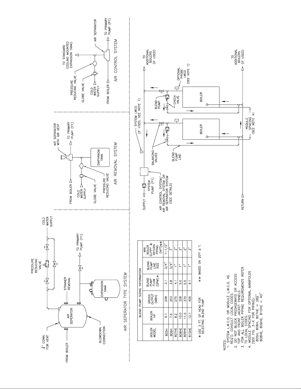
PIPING DIAGRAM (2 BOILERS), PARALLEL WITH BLEND PUMP AND SYSTEM PUMP
FIGURE 3-1
39
Page 40

PIPING DIAGRAM (2 BOILERS), PRIMARY/SECONDARY WITH BY-PASS AND SYSTEM PUMP
FIGURE 3-2
40
Page 41
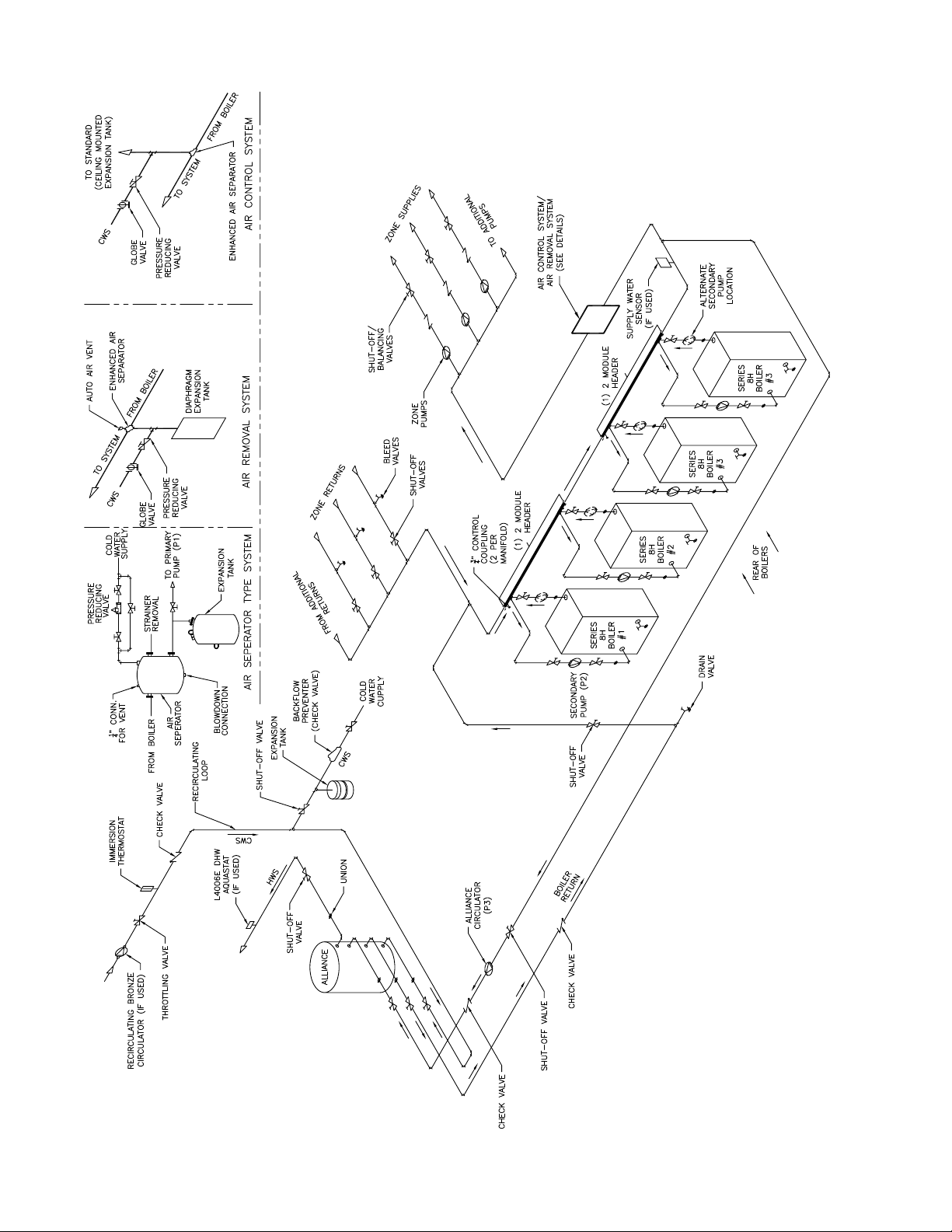
FIGURE 3-3
PIPING DIAGRAM - ZONE PUMPS, PRIMARY/SECONDARY W/ ALLIANCE DHW & RECIRC. LOOP WITH MODULAR MANIFOLDS
41
Page 42
Module Size Flow Rate (GPM)
21 20°F 1½" 3'
Temp. Rise
Thru Module
Min. Module
Piping (NPT)
Module
Pressure Drop
805H
806H
807HE
808HE
809HE
14 30°F 1¼" 2'
10 40°F 1¼" 1'
25 20°F 1½" 3'
17 30°F 1½" 2'
13 40°F 1¼" 1'
28 20°F 2" 3'
18 30°F 1½" 2'
14 40°F 1¼" 1'
33 20°F 2" 3'
22 30°F 1½" 3'
17 40°F 1½" 2'
37 20°F 2" 3'
25 30°F 2" 2'
19 40°F 1½" 1'
810HE
41 20°F 2" 3'
27 30°F 2" 2'
21 40°F 1½" 1'
1) In a primary-secondary pumping installation temperature rise thru the module has
no relation to system ∆T. In a parallel pumping installation temperature rise thru
the module equals the temperature drop of the system.
2) In a primary-secondary pumping installation pressure drop thru the module does
not add to system circulator head. In a parallel pumping installation pressure drop
thru the module does add to system circulator head load.
3) 40°F Temperature rise thru module recommended for Primary-Secondary pumping.
MODULE WATER FLOW DATA
FIGURE 3-4
42
Page 43

HEAT CONVEYED PER HOUR, MBH, WITH 20°F TEMPERATURE DROP
FRICTION VS WATER FLOW - IRON PIPE
TO USE THIS FIGURE: (1) ENTER HORIZONTAL SCALE AT DESIRED FLOW, (2) MOVE
DOWN VERTICALLY TO UPPER LIMIT OF UNSHADED AREA, (3) PICK OFF MINIMUM PIPE
SIZE ON DIAGONAL LINES SLOPING UPWARD TO THE RIGHT. (4) PICK OFF WATER
VELOCITY ON DIAGONAL LINES SLOPING UPWARD TO THE LEFT.
FIGURE 3-5
43
Page 44
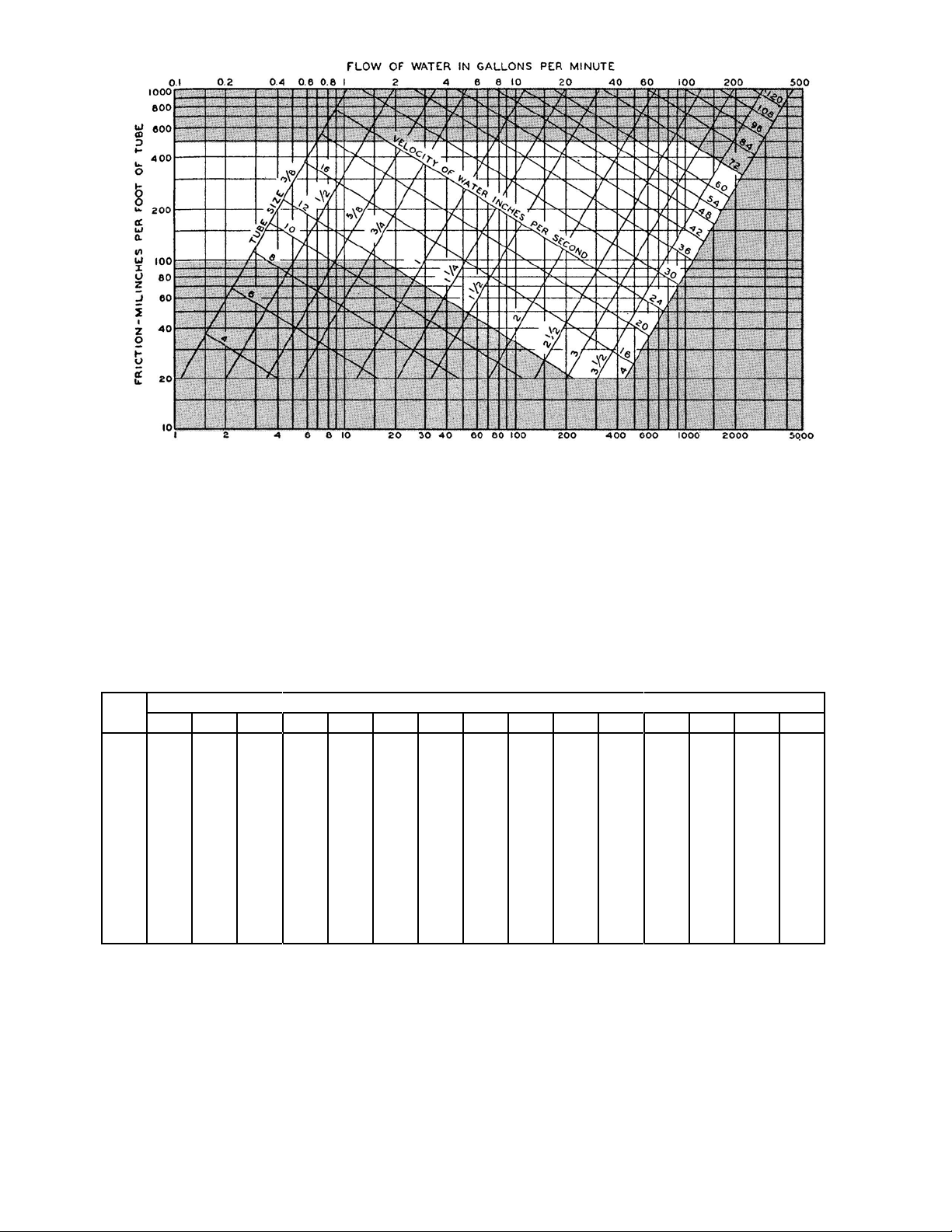
HEAT CONVEYED PER HOUR, MBH, WITH 20°F TEMPERATURE DROP
FRICTION VS WATER FLOW - COPPER PIPE
To use this Figure: (1) Enter horizontal scale at desired ow. (2) Move down vertically to
upper limit of unshaded area, (3) Pick off minimum pipe size on diagonal lines sloping upward
to the right. (4) Pick off water velocity on diagonal lines sloping upward to the left.
FIGURE 3-6
Vol.
Fps
10 1.8 2.5 3.2 4.3 5.1 6.5 7.8 9.7 11.2 12.4 15.2 17.7 22.2 27.0 32.0
½ ¾ 1 1¼ 1½ 2 2½ 3 3½ 4 5 6 8 10 12
1 1.2 1.7 2.2 3.0 3.5 4.5 5.4 6.7 7.7 8.6 10.5 12.2 15.4 18.7 22.2
2 1.4 1.9 2.5 3.3 3.9 5.1 6.0 7.5 8.6 9.5 11.7 13.7 17.3 20.8 24.8
3 1.5 2.0 2.7 3.6 4.2 5.4 6.4 8.0 9.2 10.2 12.5 14.6 18.4 22.3 26.5
4 1.5 2.1 2.8 3.7 4.4 5.6 6.7 8.3 9.6 10.6 13.1 15.2 19.2 23.2 27.6
5 1.6 2.2 2.9 3.9 4.5 5.9 7.0 8.7 10.0 11.1 13.6 15.8 19.8 24.2 28.8
6 1.7 2.3 3.0 4.0 4.7 6.0 7.2 8.9 10.3 11.4 14.0 16.3 20.5 24.9 29.6
7 1.7 2.3 3.0 4.1 4.8 6.2 7.4 9.1 10.5 11.7 14.3 16.7 21.0 25.5 30.3
8 1.7 2.4 3.1 4.2 4.9 6.3 7.5 9.3 10.8 11.9 14.6 17.1 21.5 26.1 31.0
9 1.8 2.4 3.2 4.3 5.0 6.4 7.7 9.5 11.0 12.2 14.9 17.4 21.9 26.6 31.6
Pipe Size
EQUIVALENT LENGTH OF PIPE FOR 90° ELBOWS
To use this table: (1) Enter left hand column at desired water velocity, (2) Move horizontally to
the right to the right to the column headed by the desired pipe size. (3) Read the equivalent
length of pipe for each 90° elbow to be added to the measured length at the piping circuit.
FIGURE 3-7
44
Page 45
Size ½ ¾ 1 1¼ 1½ 2 2½ 3 4 5 6 8 10 12
Copper Tube .012 .025 .043 .065 .092 .161 .250 .357 .625 1.00 1.40 2.43 3.78 5.40
Steel Pipe .016 .028 .045 .078 .102 .172 .250 .385 .667 1.00 1.50 2.63 4.20 5.90
VOLUME OF WATER IN STEEL PIPE AND COPPER TUBE - GAL/FT
TO USE THIS TABLE: (1) ENTER LEFT HAND COLUMN AT DESIRED TYPE OF
PIPE, (2) MOVE TO THE RIGHT TO THE DESIRED PIPE SIZE, (3) READ THE
RESULTING GALLONS PER FOOT OF PIPE.
FIGURE 3-8
Water Vol.
In Gallons
10 0.6 0.8 1.0 1.3 1.6 1.9 2.0
20 1.2 1.7 2.0 2.6 3.2 3.8 4.1
30 1.8 2.5 3.0 4.0 4.8 5.7 6.1
40 2.4 3.3 4.0 5.3 6.4 7.6 8.2
50 3.0 4.2 5.0 6.6 8.0 9.5 10
60 3.6 5.0 6.0 7.9 9.7 11 12
70 4.2 5.8 7.0 9.2 11 13 14
80 4.7 6.7 8.0 11 13 15 16
90 5.3 7.5 9.0 12 14 17 18
100 5.9 8.0 10 13 15 19 20
200 12 17 20 26 32 38 41
300 18 25 30 40 48 57 61
400 24 33 40 53 64 76 82
500 30 42 50 66 80 95 102
600 36 50 60 79 97 114 122
700 42 58 70 92 113 133 143
800 47 67 80 110 129 150 163
900 53 75 90 120 145 170 184
1000 59 80 100 130 161 190 200
2000 120 170 200 260 320 380 410
3000 180 250 300 400 480 570 610
4000 240 330 400 530 640 760 820
5000 300 420 500 660 800 950 1020
6000 360 500 600 790 970 1140 1220
8000 470 670 800 1100 1290 1500 1630
10000 590 800 1000 1300 1610 1900 2000
150° 160° 180° 200° 220° 240° 250°
Mean Design Water Temperature °F
COMPRESSION TANK SELECTION TABLE - CAPACITY IN GALLONS
To use this table: (1) Enter left hand column at water volume of the system, (2)
Move to the right to the maximum water temperature of the system. (3) Read
the uncorrected tank size, (4) Proceed to Figure 3-10.
FIGURE 3-9
45
Page 46
Allowable System Pressure Increase*
6 psi 8 psi 10 psi 12 psi 14 psi 16 psi 20 psi 25 psi 30 psi 40 psi 50 psi 75 psi
4 psi 1.0 .8 .68 .62 .59 .55 .5 .49 .48 .48 .48 .48
8 psi 1.6 1.2 1.05 .92 .85 .8 .7 .65 .6 .5 .5 .5
12 psi 2.0 1.7 1.43 1.25 1.15 1.07 .95 .8 .75 .63 .55 .54
18 psi 3.0 2.55 2.2 1.94 1.75 1.6 1.35 1.15 .98 .8 .72 .7
24 psi 4.6 3.65 3.1 2.65 2.38 2.15 1.78 1.52 1.35 1.12 1.02 1.0
30 psi --- 5.0 4.2 3.6 3.1 2.7 2.3 1.9 1.8 1.43 1.25 1.1
Initial Pressure On
Compression Tank
38 psi --- --- 5.3 4.6 4.1 3.7 3.05 2.5 2.25 1.95 1.7 1.4
50 psi --- --- --- --- --- --- 4.7 3.9 3.1 2.6 2.3 2.0
60 psi --- --- --- --- --- --- --- 4.5 3.8 3.1 2.7 2.4
70 psi --- --- --- --- --- --- --- --- 5.2 3.9 3.5 3.1
CORRECTION FACTOR FOR COMPRESSION TANK SELECTION
* Relief Valve setting minus initial pressure on Relief Valve, pump on.
FIGURE 3-10
FIGURE 3-11
NET EXPANSION FACTORS FOR WATER
Net Expansion Factors for Water, Based on 40°F
110° - .0075 140° - .0133 170° - .0231 200° - .0354 230° - .0477
120° - .0093 150° - .0157 180° - .0272 210° - .0395 240° - .0518
100° - .0060 130° - .0112 160° - .0190 190° - .0313 220° - .0436
To use this table: (1) Enter left hand column at initial pressure, (2) Move to the right to
column headed with the allowable system pressure increase, (3) Read correction factor. (4)
Multiply correction factor by the uncorrected tank size found from Figure 3-9 to obtain the
corrected compression tank size.
To use this table: (1) For the system water temperature, read the expansion factor
directly. (2) Multiply the expansion factor by the system volume to nd the acceptance
volume of the diaphragm type tank. (3) Proceed to Figure 3-12.
46
Page 47
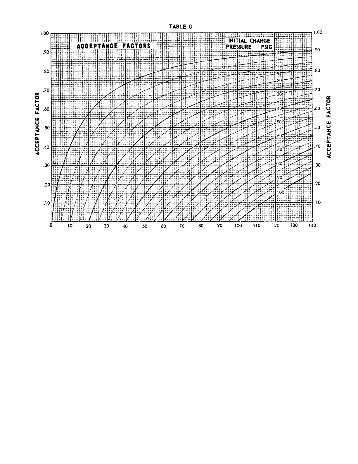
FINAL PRESSURE PSIG (NOT NECESSARILY RELIEF VALVE SETTING)
ACCEPTANCE FACTORS FOR DIAPHRAGM TYPE TANKS
To use this Figure: (1) Enter the horizontal scale at the nal system pressure. (2)
Move up vertically to the curved line for the initial charge pressure. (3) Read the
acceptance factor on the vertical scale. (4) Divide acceptance volume from Figure
3-11 by the acceptance factor to obtain diaphragm type tank volume.
FIGURE 3-12
Module Size
Heating Surface,
2
Ft
Water Volume,
805H 34.4 11.9
806H 42.6 13.9
807HE 50.8 15.9
808HE 59.0 17.9
809HE 67.2 19.9
810HE 75.4 21.9
MODULE DATE - WATER SIDE
FIGURE 3-13
Gallon
47
Page 48

RECOMMENDED WATER PIPING FOR DOMESTIC WATER HEATER
48
FIGURE 3-14
Page 49

Apartment
House
Basins, Private Lavatory ¾ ¾ ¾ ¾ ¾ ¾ ¾ ¾ ¾
Basins, Public Lavatory --- 1 1 1 1 1 1 1 1
Bathtubs 1½ 1½ --- 1½ 1½ --- --- --- ---
Dishwashers 1½ Five (5) Fixture Units per 250 seating capacity
Therapeutic Bath --- --- --- 5 --- --- --- --- ---
Kitchen Sink ¾ 1½ --- 3 1½ 3 --- ¾ 3
Pantry Sink --- 2½ --- 2½ 2½ --- --- 2½ 2½
Slop Sink 1½ 2½ 2½ 2½ 2½ 2½ 2½ 2½
Showers* 1½ 1½ 1½ 1½ 1½ 3 --- 1½ 1½
Circular Wash Fountain --- 2½ 2½ 2½ --- 4 --- 2½ 2½
Semi-circular Wash
Fountain
* In applications where principal use is showers, as in gymnasiums or at end of shift in industrial plants, use conversion factor of
1.00toobtaindesignwaterowrateingpm.
--- 1½ 1½ 1½ --- 3 --- 1½ 1½
Club Gymnasium Hospital
Hotels and
Dormitories
Industrial
Plant
Ofce
Bldg.
School YMCA
SERVICE HOT WATER DEMAND, FIXTURE UNITS
TO USE THIS TABLE: (1) FOR THE TYPE OF FIXTURE AND TYPE OF BUILDING, READ DIRECTLY
THE FIXTURE UNITS. (2) MULTIPLY THE FIXTURE UNITS BY THE TOTAL NUMBER OF FIXTURES
OF ONE TYPE. (3) ADD TOGETHER THE FIXTURE UNITS FOR EACH TYPE TO OBTAIN THE TOTAL
FIXTURE UNITS FOR THE BUILDING. (4) PROCEED TO FIGURE 3-16.
FIGURE 3-15
SERVICE HOT WATER FLOW RATE
TO USE THIS FIGURE: (1) ENTER THE HORIZONTAL SCALE AT THE TOTAL FIXTURE UNITS
OBTAINED FROM FIGURE 3-15. (2) MOVE UP VERTICALLY TO THE CURVE MARKED FOR THE TYPE
OF BUILDING. (3) READ THE REQUIRED SERVICE WATER FLOW RATE ON THE VERTICAL SCALE.
FIGURE 3-16
49
Page 50

SIZING FACTORS FOR COMBINATION HEATING / SERVICE WATER BOILERS
TO USE THIS FIGURE: (1) CALCULATE RATIO OF HOT WATER HEATING LOAD TO
HEATING LOAD. (2) ENTER HORIZONTAL SCALE AND MOVE UPWARD TO THE
CURVE. (3) READ HOT WATER HEATING LOAD FACTOR ON THE VERTICAL SCALE.
(4) MULTIPLY FACTOR BY THE HEATING LOAD TO OBTAIN THE HOT WATER "ADDED
BOILER CAPACITY." (5) SELECT MODULES WITH TOTAL NET RATING EQUAL TO
HEATING LOAD PLUS HOT WATER "ADDED BOILER CAPACITY."
FIGURE 3-17
50
Page 51

SECTION 4.0 – GAS PIPING
Failure to properly pipe gas supply to boiler may
result in improper operation and damage to the
boiler or structure. Always assure gas piping is
absolutely leak free and of the proper size and
type for the connected load.
An additional gas pressure regulator may be
needed. Consult gas supplier.
Failure to use proper thread compounds on all
gas connectors may result in leaks of ammable
gas.
Gas supply to boiler and system must be
absolutely shut off prior to installing or servicing
boiler gas piping.
4.1 General – Breeching ducts and water pipes are
generally less exible in design location than are gas
pipes. To avoid conicts for a given location, design
and layout breeching ducts and water piping before
proceeding with gas piping in this section.
4.2 Gas Piping Design and Layout – On a scaled drawing
of the boiler room locate the boiler modules as
planned in SECTION 2. Locate the gas meter on the
drawing. Observe that the opening in the module
jacket for gas piping is on the top surface at the right
side front corner. The gas connection to the module
gas train is inside the module vestibule and on the
right side 12” above the oor.
4.2.1 Using Figures 4-1 and 4-2 decide on the simplest
piping arrangement for the module layout. The
location of the gas meter in relation to the modules
has a large effect on the length and size of the gas
piping. Long mains with many ttings should be
avoided as the minimum pipe size required increases
as the length of pipe and number of ttings increases.
For this reason it is desirable to ask the gas supplier
to set the gas meter as close to the boiler room as
possible.
4.2.3 On the plans, draw the gas piping using the shortest
possible route from meter to modules while observing
the need to keep passageways open around all
modules for servicing. It is highly recommended that
the gas main be located horizontal, at the ceiling level
of the boiler room, and directly over the front base
line of the modules. The branch lines from the main
should be vertical and direct to the modules.
4.2.4 On the plans, measure the total distance, including
vertical runs, from the gas meter to the furthest
module, and count the main tting ells in that furthest
run. (Straight ow through a tee is not counted as a
tting)
4.2.5 Obtain from the gas supplier the following
information:
a) type of gas (natural or propane)
b) specic gravity
c) heating value
4.3 Gas Pipe Sizing (Preferred Method)
4.3.1 Figure 4-3 may be used for sizing pipes and ttings if
all of the following conditions are met:
a) the distance from the gas meter to the furthest
module is no more than fty feet and has no more
than three ells, and
b) the maximum supply gas pressure at the meter is
0.5 psig, and
c) the maximum supply gas pressure drop is 0.3
inches water column, and
d) the specic gravity of the gas is between 0.64 and
0.70 for natural or 1.50 and 1.63 for propane, and
e) the heating value of the gas is either 1000 Btu/Ft3
for propane.
4.3.2 The procedure for sizing using Figure 4-3 is as
follows:
1) Total the Input MBH (from gure 2-3) of all
modules to be supplied by the gas pipe (and/or
tting) to be sized.
2) Locate this value in the left column.
3) Move to the right to the appropriate gas column,
either Natural or Propane.
4) Read the pipe and/or tting size. Record this on
the gas pipe drawing.
5) The size of individual module supply piping -A,
and the manual valve-B, should correspond to the
Gas Connection size as tabulated in Figure 2-3.
Record these sizes on the gas pipe drawing.
Example #1: Eight 809HE modules are to be piped in
line, similar to Figure 4-1, on natural gas.
Size the piping:
1) A check of the conditions for this job shows the
measured length of pipe from the gas meter to
the furthest module is 45 ft with 3 ells. The gas
supplier says that his system will deliver 4224
cubic feet at 0.5 psig at the meter, and his gas has
0.65 specic gravity and 1000 Btu/Ft3 heating
value. Figure 4-3 can be used.
2) The piping (D8) between the gas meter and the rst
module take-off (C8) serves eight modules. From
Figure 23, each 809HE module requires 460 MBH
Input. 8 x 460 = 3680. MBH- Total Input thru D8.
3) Enter the left column in Figure 4-3 with 3680 total
input MBH, which falls between the gure values
of 3630-5610.
4) Read across to the “Natural Gas” column and pick
off a pipe/tting size of 4”. Record this on the gas
pipe drawing as D8.
51
Page 52

5) The next piping segment, D7, serves seven
modules. 7 x 460 = 3220 MBH – Total Input thru
D7.
6) Enter Figure 4-3 with 3220 Total Input MBH and
again pick off a pipe/tting size of 4”. Record this
as D7.
7) In like manner:
D6 = 3” D3 = 2½”
D5 = 3” D2 = 2”
D4 = 3” D1, C1 = 1½”
8) Since all modules require the same input MBH, D1
– 1½” applies to the vertical drops to each module.
9) From Figure 2-3 the modules’ Gas Connection size
is determined to be 1” MPT (non-IRI assumed for
this example).
10) Record each module’s supply piping (A) and
manual valve (B) sizes as 1”.
11) By inspection the reducing tee ttings © in the
horizontal gas line can be sized based on the
adjacent pipe sizes.
C8 is between D8 which is 4” and D7 which is also
4” and feeds D1 which is 1½”. Hence C8 should be
recorded on the drawing as 4” x 4” x 1½”.
12) In like manner:
C7 = 4 x 3 x 1½ C4 = 3 x 2½ x 1½
C6 = 3 x 3 x 1½ C3 = 2½ x 2 x 1½
C5 = 3 x 3 x 1½ C2 = 2 x 1½ x 1½
13) Record all pipe and tting sizes on the gas pipe
drawing for reference during installation.
4.4 Gas Pipe Sizing (Alternate Method)
4.4.1 If all of the conditions for using Figure 4-3 are not
met, the following procedure must be used to size gas
piping:
1) Determine the total equivalent length of pipe from
the meter to the furthest module by adding to the
measured length the equivalent length of each
tting from Figure 4-4. (Straight thru ow through
a tee is not considered a tting).
2) Determine the actual cubic feet of gas to be
carried by the main segment by dividing the BTU
requirement by the heating value of the gas.
3) Determine the equivalent cubic feet of .60 specic
gravity gas by multiplying the actual cubic feet
from 2) above by the appropriate specic gravity
multiplier from Figure 4-6.
4) Enter Figure 4-5 under column for the total
equivalent length of pipe as found in 1) above.
5) Read down until nding a number equal to or
greater than the equivalent cubic feet from 3)
above, which the main segment is required to
carry.
6) Read across to the left hand column and pick off
the minimum pipe size required.
Example #2: Eight 809HE modules are to be piped in
line with propane from a tank source 115 feet from the
furthest module and 8 ells are in the supply line. The
propane to be used has a specic gravity of 1.40 and a
heating value of 2420 Btu/Ft3. Size the piping:
a) To the measured length of 115’ add the equivalent
length of 8 ells x 10.1 Ft/Ell for a total equivalent
of 195.8 Ft. (The factor of 10.1 comes from Figure
4-4 under the column for ells at an estimated 4”
main size.)
b) The actual cubic feet required in main D8 is
8 (modules) x 460,000 (Btu/809HE) = 1521 Ft3/Hr
2420 (BTU/Ft3)
In a like manner the actual cubic feet required in the
remaining main segments are found to be:
Flow D7 = 7 x 460,000 ÷ 2420 = 1331 Ft3/Hr
Flow D6 = 6 x 460,000 ÷ 2420 = 1141 Ft3/Hr
Flow D5 = 5 x 460,000 ÷ 2420 = 950 Ft3/Hr
Flow D4 = 4 x 460,000 ÷ 2420 = 760 Ft3/Hr
Flow D3 = 3 x 460,000 ÷ 2420 = 570 Ft3/Hr
Flow D2 = 2 x 460,000 ÷ 2420 = 380 Ft3/Hr
Flow D1 = 1 x 460,000 ÷ 2420 = 190 Ft3/Hr
c) Enter gure 4-6 at a specic gravity of 1.40 and
note the multiplier of 1.3. Tabulate equivalent ow
rates for each pipe segment as follows:
Equiv. Flow D8 = 1521 x 1.53 = 2327 Ft3/Hr
Equiv. Flow D7 = 1331 x 1.53 = 2036 Ft3/Hr
Equiv. Flow D6 = 1141 x 1.53 = 1746 Ft3/Hr
Equiv. Flow D5 = 950 x 1.53 = 1454 Ft3/Hr
Equiv. Flow D4 = 760 x 1.53 = 1163 Ft3/Hr
Equiv. Flow D3 = 570 x 1.53 = 872 Ft3/Hr
Equiv. Flow D2 = 380 x 1.53 = 581 Ft3/Hr
Equiv. Flow D1 = 190 x 1.53 = 291 Ft3/Hr
d) Enter Figure 4-5 from the top at column marked
200 Ft. of pipe. The length found in a) above was
195.8 Ft. which is between column marked 175
and 200 Ft. Use next larger of 200 Ft.
e) Read down until nding a number equal to
or greater than the equivalent cubic foot ow
requirement found in c) above.
f) Read across to the left hand column and pick off
the following required minimum pipe sizes:
Size D8 = 4”
Size D7 = 4”
Size D6 = 4”
Size D5 = 3”
Size D4 = 3”
Size D3 = 2½”
Size D2 = 2”
Size D1 = 1½”
g) D1 = 1½” becomes the vertical riser from each of
the modules to the overhead horizontal main.
h) Mark all pipe sizes on the plan for reference during
installation.
4.5 Gas Pipe Installation
With modules fully assembled, including jackets,
install gas supply piping in accordance with the
current edition of “National Fuel Gas Code” (ANSI
52
Page 53

Z223.1) and all requirements of the gas supplier and
municipality.
4.5.1 Please consider the serviceman who must periodically
clean and adjust the modules, and repair accessories.
Do not block passageways with piping. Do not block
access panels on the module jackets.
4.5.2 Material – Use only Schedule 40 black iron pipe.
Make sure all threads are fully formed and free of
burrs. Threaded joints should be sealed with an
approved compound to prevent leaks.
4.5.3 Traps – Install a trap similar to that shown in Figure
4-8 at the low end of the vertical run to each module.
4.5.4 Supports – Pipe supports should be installed according
to Figure 4-7. Supports should encircle the pipe at
ceiling level but allow movement for expansion of
the piping. The weight of the gas piping must not be
placed upon the module gas connection.
4.5.5 Grounding – Gas piping must be grounded. If any
non-conductive ttings are used they must be bridged
with an appropriately sized ground wire. Particular
attention should be given to a propane system with
above ground tank(s). Such tank(s) must be externally
grounded.
4.5.6 Leak Testing – If the gas lines have been designed
according to preceding sections of this manual, the
operating gas pressure will be 0.5 psig. Under such
pressure, fuel gas may be used for leak testing. On
each module, turn the manual portion of combination
valve to off position before applying gas pressure.
Immediately after applying gas pressure, apply leak
check solution to all gas piping and observe piping for
leaks. Repair any leaks found and retest piping. If the
gas supplier requires leak testing at pressures higher
than 0.5 psig, or with inert gas, follow that required
procedure in full.
4.6 Gas Piping Maintenance – Piping should be inspected
annually or after any extended shut down period. If
the normal operating gas pressure is 0.5 psig or less,
fuel gas can be used for leak detection as described in
4.5.6 above.
4.6.1 Any pipe or tting showing unusual rust or corrosion
should be replaced.
4.6.2 Gas piping should not be used as an electrical
conductor. Relocate any electrical circuit which is
found to be using the gas piping as a conductor.
Note: Many municipalities allow light weight, low
voltage, well insulated electrical wire to be supported
on the gas piping with approved non-conductive
fasteners.
4.6.3 Gas piping should not be used to support any other
pipe or heavy object. Find other means to support any
such heavy object.
4.6.4 Traps should be cleaned at least once every two
years. Turn off gas supply, remove cap below tee, as
shown in Figure 4-8, and clean out all moisture and
foreign material. Replace cap and check for leaks as
described in 4.5.6 above.
53
Page 54

RECOMMENDED GAS SUPPLY PIPING - 1 THRU 8 MODULES IN LINE OR CORNERED.
(ALL PIPING SHOWN SUPPLIED BY INSTALLER)
FIGURE 4-1
54
Page 55

RECOMMENDED GAS SUPPLY PIPING - TWO ROWS OF 1 THRU 4 MODULES
EACH BACK-TO-BACK OR CORNERED, OR 1 THRU 8 MODULES IN LINE.
(ALL PIPING SHOWN SUPPLIED BY INSTALLER)
FIGURE 4-2
55
Page 56

NOTICE
Use this table only if all of the following conditions
are met:
1) 50 Ft. maximum plus 3 ells from Meter to furthest
Module Gas Connection
2) 0.5 PSIG Maximum Gas Pressure
3) 0.3 Inch Water Column Pressure Drop
4) Specic Gravity of Natural Gas = 0.64 to 0.70
Propane = 1.50 to 1.63
5) Heating value of
Natural Gas = 1000 Btu/Ft
Propane Gas = 2500 Btu/Ft
3
3
Otherwise, refer to the Alternate Method of Gas Pipe
Sizing in 4.4.
Total Input MBH of
Pipe/Fitting Size (NPT)
Module(s) Served
by Pipe/Fitting
264. - 330. 1¼" 1"
396. 1¼" 1¼"
462. - 660. 1½" 1¼"
726. - 990. 2" 1½"
1056. - 1254. 2" 2"
1320. - 1980. 2½" 2"
2046. - 3102. 3" 2½"
3168. - 3564. 3" 3"
3630. - 5610.
Natural Gas Propane Gas
4" 3"
To use this table: (1) Total the Input MBH (from
Figure 2-3) of all modules to be supplied by the
gas pipe (and/or tting) to be sized (2) Locate this
Total MBH in the left column (3) Move to the right
to the appropriate gas column (4) Read the pipe
and/or tting size.
FIGURE 4-3
Nominal
Pipe Size,
In.
½ 0.622 0.73 1.55 3.47 3.10 0.36 17.3 8.65 4.32
¾ 0.824 0.96 2.06 4.60 4.12 0.48 22.9 11.4 5.72
1 1.019 1.22 2.62 5.82 5.24 0.61 29.1 14.6 7.27
1¼ 1.380 1.61 3.45 7.66 6.90 0.81 38.3 19.1 9.58
1½ 1.610 1.88 4.02 8.95 8.04 0.94 44.7 22.4 11.2
2 2.067 2.41 5.17 11.5 10.3 1.21 57.4 28.7 14.4
2½ 2.469 2.88 6.16 13.7 12.3 1.44 68.5 34.3 17.1
3 3.068 3.58 7.67 17.1 15.3 1.79 85.2 42.6 21.3
4 4.026 4.70 10.1 22.4 20.2 2.35 112 56.0 28.0
5 5.047 5.88 12.6 28.0 25.2 2.94 140 70.0 35.0
Inside Dia.,
Schedule 40,
In.
45° Ell 90° Ell
Screwed Fittings
180° Close
Return Bends
Tee Gate Globe Angle
Valves (screwed, anged, or
welded)
Swing
Check
EQUIVALENT LENGTH OF FITTINGS AND VALVES - GAS PIPE (FT)
TO USE THIS TABLE: (1) ENTER LEFT HAND COLUMN AT REQUIRED PIPE SIZE. (2) MOVE TO THE RIGHT
TO THE RIGHT TO THE COLUMN FOR THE TYPE OF FITTING. (3) READ THE EQUIVALENT LENGTH OF
STRAIGHT PIPE FOR THAT ONE FITTING. (4) TOTAL THE EQUIVALENT LENGTH FOR EVERY FITTING IN
THE SUPPLY LINE. (5) ADD THE TOTAL EQUIVALENT LENGTH FOR FITTINGS TO THE MEASURED LENGTH
OF STRAIGHT PIPE TO OBTAIN THE EQUIVALENT LENGTH OF THE SUPPLY LINE.
56
FIGURE 4-4
Page 57
Nominal
Iron Pipe
Size, In.
1/4 .364 32 22 18 15 14 12 11 11 10 9 8 8 7 6
3/8 .493 72 49 40 34 30 27 25 23 22 21 18 17 15 14
1/2 .622 132 92 73 63 56 50 46 43 40 38 34 31 28 26
3/4 .824 278 190 152 130 115 105 96 90 84 79 72 64 59 55
1 1.049 50 350 285 245 215 195 180 170 160 150 130 120 110 100
1-1/4 1.380 1,050 730 590 500 440 400 370 350 320 305 275 250 225 210
1-1/2 1.610 1,600 1,100 890 760 670 610 560 530 490 460 410 380 350 320
2 2.067 3,050 2,100 1,650 1,450 1,270 1,150 1,050 990 930 870 780 710 650 610
2-1/2 2.469 4,800 3,300 2,700 2,300 2,000 1,850 1,700 1,600 1,500 1,400 1,250 1,130 1,050 980
3 3.068 8,500 5,900 4,700 4,100 3,600 3,250 3,000 2,800 2,600 2,500 2,200 2,000 1,850 1,700
4 4.026 17,500 12,000 9,700 8,300 7,400 6,800 6,200 5,800 5,400 5,100 4,500 4,100 3,800 3,500
Internal
Dia., In.
10 20 30 40 50 60 70 80 90 100 125 150 175 200
Length of Pipe, Feet
MAXIMUM CAPACITY OF PIPE (FT3/HR)
(Based on gas pressure at 0.5 psig., pressure drop of 0.3" water column, and 0.60 specic gravity.)
TO USE THIS TABLE: (1) ENTER THE TOP ROW AT THE TOTAL EQUIVALENT LENGTH OF PIPE OBTAINED
FROM 4.4.1 - 1). (2) MOVE DOWN TO THE EQUIVALENT GAS FLOW OBTAINED FROM 4.4.1 - 3). (3) MOVE
ACROSS TO THE LEFT HAND COLUMN. (4) READ THE REQUIRED PIPE SIZE.
FIGURE 4-5
SpecicGravity Multiplier SpecicGravity Multiplier
.35 .763 1.00 1.29
.40 .813 1.10 1.35
.45 .862 1.20 1.40
.50 .909 1.30 1.47
.55 .962 1.40 1.53
.60 1.00 1.50 1.58
.65 1.04 1.60 1.63
.70 1.08 1.70 1.68
.75 1.12 1.80 1.73
.80 1.15 1.90 1.77
.85 1.19 2.00 1.83
.90 1.22 2.10 1.87
CORRECTION FACTORS FOR SPECIFIC GRAVITY OTHER THAN .60
To use this table: (1) Read directly the multiplier for the specic gravity of the gas to be used. (2) Multiply actual
gas ow rates by this multiplier to obtain equivalent ow rates for .60 specic gravity gas. (3) Enter Figure 4.5 with
these equivalent gas ow rates to determine gas pipe sizes.
FIGURE 4-6
57
Page 58
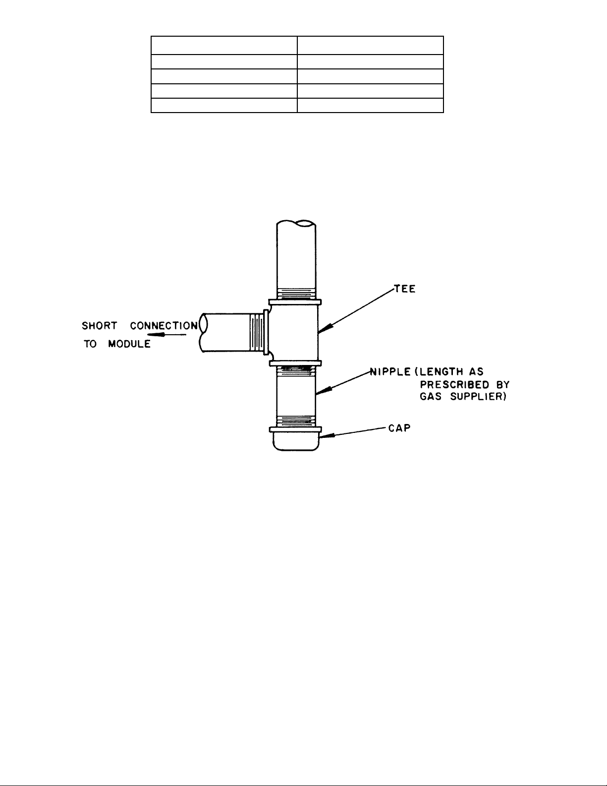
Size of Pipe (Inches) Spacing of Supports (Feet)
½ 6
¾ or 1 8
1¼ or larger (horizontal) 10
1¼ or larger (vertical) Everyoorlevel
SUPPORT OF PIPING
FIGURE 4-7
58
ALL PIPE AND FITTINGS TO BE SIZED ACCORDING TO MODULE SUPPLY PIPE SIZE
MOISTURE AND DIRT TRAP
FOR GAS SUPPLY TO EACH MODULE
SERIES 8H/8HE MODULAR GAS BOILER
FIGURE 4-8
Page 59

SECTION 5.0 – CONTROLS
Positively assure all electrical connections are unpowered before attempting installation or service of
electrical components or connections of the boiler or building. Lock out all electrical boxes with padlock
once power is turned off.
Failure to properly wire electrical connections to the boiler may result in serious physical harm.
Electrical power may be from more than one source. Make sure all power is off before attempting any
electrical work.
Each boiler must be protected with a properly sized fused disconnect.
Never jump out or make inoperative any safety or operating controls.
The wiring diagrams contained in this manual are for reference purposes only. Each boiler is shipped with
a wiring diagram attached to the front door. Refer to this diagram and the wiring diagram of any controls
used with the boiler. Read, understand and follow all wiring instructions supplied with the controls.
5.1 General – Breeching ducts, water piping and gas
piping are generally less exible than are electrical
conductors. To avoid conicts for the same location,
design and layout breeching ducts, water and gas
piping before proceeding with electrical and control
layout in this section.
5.1.1 Selection of the control package should be based on:
1) The application or end use of the heat supplied by
the modules (ie: is the application for space heating
only, or will it be used for space and domestic hot
water requirements).
2) The number of boilers being controlled.
5.1.2 Burnham Commercial offers Tekmar boiler staging
controls that can stage and rotate up to eight modules.
All Tekmar controls use PID logic for precise control
over the desired supply water or domestic hot water
temperature or both. Use the table below for selecting
the proper control for the number of boilers being
used.
59
Page 60
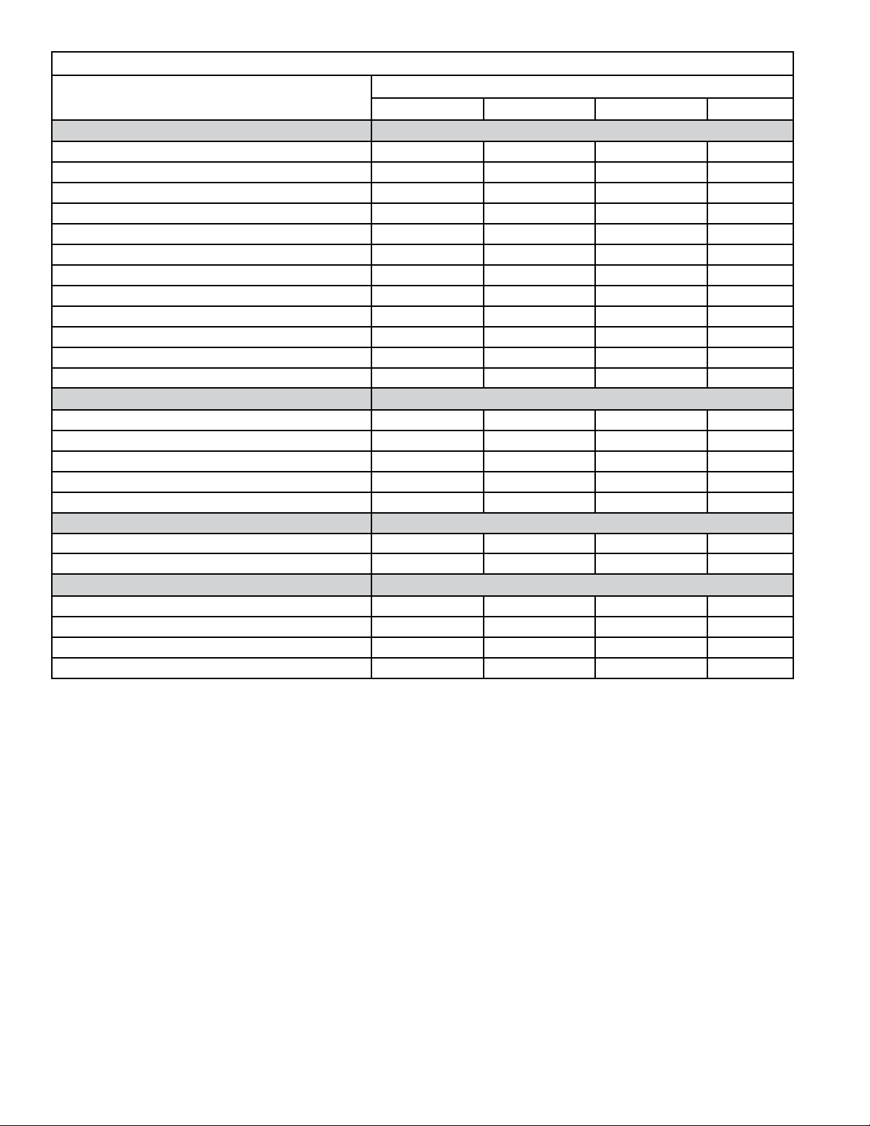
Boiler Staging Control Features
Feature:
261 263 274 268
Boiler Operation
Number of Stages 2 2 4 9
Boiler Differential A/M A/M A/M A/M
Boiler Minimum Supply M M M M
Boiler Outdoor Reset o o o o
Boiler Post Purge F M M M
Characterized Heating Curve o o o o
Equal Run Time Rotation o o o o
PID Staging o o o o
Fire Delay M M M M
Interstage Delay A A A/M A/M
External EMS Input Signal (0-10Vdc) o o
Warm Weather Shut Down o o o o
Domestic Hot Water (DHW) Operation
DHW Priority With Reset Override o o o
DHW External Demand (Aquastat) o o o
DHW Internal Demand (Sensor) o o
DHW Post Purge o o o
DHW Setback o o o
Setpoint Operation
Setpoint Production o o o
Setpoint Priority With Reset Override o o o
Other Features and Functions
Digital Display o o o
Pump Exercising o o o
Night Setback through Internal Timer o o o
Night Setback through External Timer o o o
A=AutomaticAdjustmentF=FixedM=ManualNote:Thisisapartiallistoffeatures
Tekmar Control Model Number:
60
Page 61
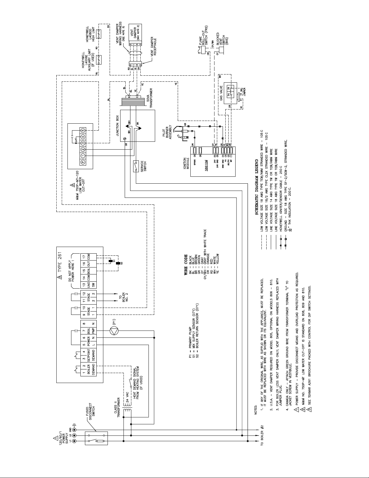
FIGURE 5-1
TEKMAR 261, TWO-STAGE, EI, FOR PARALLEL PIPING
61
Page 62

FIGURE 5-2
TEKMAR 261, TWO-STAGE, EI, FOR PRIMARY SECONDARY PIPING
62
Page 63
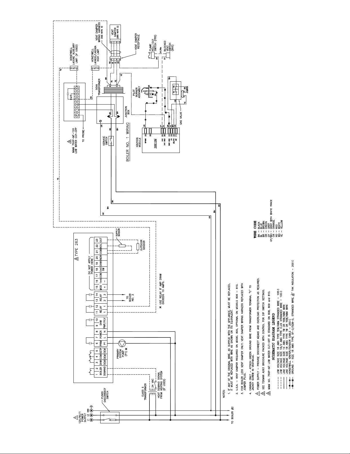
FIGURE 5-3
TEKMAR 263, TWO-STAGE, EI, FOR PARALLEL PIPING
63
Page 64

FIGURE 5-4
TEKMAR 263, TWO-STAGE, EI, FOR PRIMARY SECONDARY PIPING
64
Page 65

FIGURE 5-5
TEKMAR 274, FOUR-STAGE, EI, FOR PARALLEL PIPING
65
Page 66

FIGURE 5-6
TEKMAR 274, FOUR-STAGE, EI, FOR PRIMARY SECONDARY PIPING
66
Page 67

FIGURE 5-7
TEKMAR 268, EIGHT-STAGE, EI, FOR PARALLEL PIPING
67
Page 68

FIGURE 5-8
TEKMAR 268, EIGHT-STAGE, EI, FOR PRIMARY SECONDARY PIPING
68
Page 69

SECTION 6.0
START-UP AND SERVICE
Service on this boiler should be undertaken only by trained and skilled personnel from a qualified service
agency. Inspections should be performed at intervals specified in this manual. Maintain manual in a
legible condition.
Keep boiler area clear and free of combustible materials, gasoline and other flammable vapors and liquids.
Do not place any obstructions in boiler room that will hinder flow of combustion and ventilation air.
The service instructions contained in this manual are in addition to the instructions provided by the
manufacturer of the boiler components. Follow component manufacturer’s instructions. Component
manufacturer’s instructions were provided with the boiler. Contact component manufacturer for replacement
if instructions are missing. Do not install, start up, operate, maintain or service this boiler without reading
and understanding all of the component instructions. Do not allow the boiler to operate with altered,
disconnected or jumpered components. Only use rePLACEMENT COMPONENTS IDENTICAL TO THOSE
ORIGINALLY SUPPLIED BY BURNHAM COMMERCIAL.
6.2 TEST GAS PIPING. Test main and pilot gas piping
Completely read, understand and follow all
instructions in this manual before attempting
start-up.
WARNING - BEFORE INSTALLATION OF THE BOILER
IS CONSIDERED COMPLETE THE OPERATION
OF THE BOILER CONTROLS SHOULD ALL BE
CHECKED, PARTICULARLY THE LOW WATER CUTOFF AND THE HIGH LIMIT CONTROLS.
6.1 FILL ENTIRE HEATING SYSTEM WITH WATER
and vent air from system. Use the following
procedure on a system equipped with zone valves.
1) Close all but one zone valve.
2) Open drain valves on boilers.
3) Open ll valve.
4) Close purge valve.
5) Open relief valves on boilers.
6) Allow water to run out of drain valve until zone
has been purged of air and lled with water.
7) Open zone valve to the second zone to be purged,
then close the rst. Repeat this step until all zones
have been purged but always have one zone open.
At completion open all zone valves.
8) Close drain valve.
9) When water discharges from relief valves, release
the lever on the top of the relief valves, allowing
them to close.
10) Continue lling the system until the pressure gauge
reads 12 psi. Close ll valve.
11) Open purge valve.
12) Start system circulator.
The maximum operating pressure of this boiler is
50 psig. Never exceed this pressure. Do not plug
or modify pressure relief valve.
at boiler for leaks at all piping connections and valves.
Refer to 4.5.6.
6.3 PURGE GAS PIPING OF AIR
1) Disconnect electric service to boiler.
2) Turn control knob on all modules' combination gas
valves to off position.
3) Open valve on main gas line at meter.
4) Starting with Module #1 disconnect pilot tubing
from outlet side of combination gas valve. Depress
Control Knob slightly and turn to "Pilot" position.
Depress Knob fully and hold until gas issues from
disconnected tting. Release Knob and reconnect
pilot tubing. Turn control knob to off.
5) Repeat (4) for each module in sequence.
6.4 Make sure that pilot tubing has been reconnected.
Wait ve minutes then proceed "To Light" in
accordance with boiler operating instructions
attached to the boiler jacket. On boilers equipped
with standing pilots, light the pilot of each boiler in
sequence.
6.5 CHECK GAS INPUT rate to each boiler separately.
Input rate must not exceed that shown on Rating Plate.
For propane gas adjust regulator for a burner manifold
pressure of eleven (11.0) inches water column.
For natural gas, check input rate shown on boiler
rating plate as follows:
1) Consult local gas company for heating value of gas
(BTU/Cu. Ft.).
2) Set limit and operating control high enough so
boiler will not shut off while checking input rate.
3) All other gas burning appliances served by meter
should be turned off temporarily while checking
input rate.
4) Check manifold pressure at 1/8" tapping on burner
manifold. Pressure should be approximately
3½" water column for natural gas. Adjustment
of gas pressure can be made by turning regulator
69
Page 70

adjusting screw counterclockwise to decrease
manifold pressure (gas rate) or clockwise to
increase. Adjustment of Regulator must be within
limitations set forth by Gas Supplier.
If necessary to increase or decrease manifold
pressure more than 0.3" water for natural gas to
provide rated input, remove orice plugs installed
in burner manifold and:
a) Increase orices one (1) drill size larger to reduce
manifold pressure to that recommended, or
b) Replace orices with one (1) drill size smaller to
raise manifold pressure to that recommended.
c) Reinstall orice plugs and recheck input rate.
5) After adjusting manifold pressure to that
recommended, make a nal check on input by
clocking the gas meter. Only the gas boiler should
be in operation (make sure that all other gas
appliances connected to the same meter are not
operating). Check the gas consumption indicated
by the gas meter for three minutes for conformity
to that required and as determined by the following
formula:
Gas Input, Cu. Ft. per 3 minutes =
(Input, Btu/hr.
(Heating Value of gas, Btu/Cu. Ft.) x 20
NOTE: In the above formula, (Input, Btu/hr.) is
that shown on the Boiler rating plate, and heating
value of gas, Btu/Cu. Ft., must be obtained from
the local gas company.
I.E. Input for 5-Section Boiler is 264,000 Btu/hr.
Heating value of gas is 1,000 Btu/cu. ft.
Therefore: 264,000 = 264,000 = 13.2 cu. ft./3 min.
1,000 x 20 20,000
6) Return all control settings to their normal
positions.
6.6 ADJUST AIR SHUTTERS on Main Burners by
loosening shutter lock screw and closing them until
yellow tips appear on ames, then open shutters
slowly until clearly dened inner cones may be seen.
Tighten screws to hold the air shutters in this position.
6.7 SEQUENCE OF CONTROLS
See Section 5.0 for the sequence of controls that
applies to the system installed.
Label all wires prior to disconnection when
servicing controls. Wiring errors can cause
improper and dangerous operation. Verify proper
operation after servicing.
6.8 CLEANING BOILER FLUES AND BURNERS
Boiler ues should be inspected annually and
burners should be cleaned annually. The proper
procedures for this maintenance, including removal
and reinstallation of canopy, burners, and pilot
assemblies, are detailed and diagrammed in the
"INSTALLATION, OPERATING AND SERVICE
INSTRUCTIONS" manual supplied with each
8H/8HE Series Boiler.
For service or repairs to boiler, call our heating contractor. When seeking information on boiler, provide
Boiler, provide Boiler Model Number and Serial Number as shown on Rating Label.
Boiler Model Number Boiler Serial Number
_8_ _ _ _ _ - ____ 6_ _ _ _ _ _ _
_8_ _ _ _ _ - ____ 6_ _ _ _ _ _ _
_8_ _ _ _ _ - ____ 6_ _ _ _ _ _ _
_8_ _ _ _ _ - ____ 6_ _ _ _ _ _ _
_8_ _ _ _ _ - ____ 6_ _ _ _ _ _ _
_8_ _ _ _ _ - ____ 6_ _ _ _ _ _ _
_8_ _ _ _ _ - ____ 6_ _ _ _ _ _ _
_8_ _ _ _ _ - ____ 6_ _ _ _ _ _ _
Heating Contractor Installation Date
Address Phone Number
70
Page 71

IX. Repair Parts
All Series 8H/8HE repair parts may be obtained through your local Burnham Wholesale Distributor. Should you require
assistance in locating a Burnham Distributor in your area, or have questions regarding the availability of Burnham products or repair parts, please contact Burnham Customer Service at (717) 481-8400 or Fax (717) 481-8408.
71
Page 72
72
 Loading...