

Burkert 3363, 3365, 3364, AE3365, AE3363 Quick Start Manual
...
Quickstart
English
Type 3363, 3364, 3365 AE3363, AE3364, AE3365
Electromotive diaphragm control valve

We reserve the right to make technical changes without notice.
Technische Änderungen vorbehalten.
Sous réserve de modifications techniques.
© Bürkert Werke GmbH & Co. KG, 2016 – 2018
Operating Instructions 1810/03_EU-ML_00810536 / Original DE
Type 3363, 3364, 3365
english
Contents
1
THE QUICKSTART ..............................................................4
1.1 Definition of the term "device" ................................................ 4
1.2 Symbols ....................................................................................... 5
2 INTENDED USE .............................................................................................5
3 BASIC SAFETY INSTRUCTIONS ..........................................................6
4 GENERAL INFORMATION ........................................................................7
4.1 Contact address ........................................................................ 7
4.2 Warranty ...................................................................................... 7
4.3 Information on the Internet ......................................................7
5 STRUCTURE AND FUNCTION...............................................................8
5.1 Structure of the electromotive diaphragm control valve ... 8
5.2 Display of the device state ..................................................... 8
6 TECHNICAL DATA ........................................................................................9
6.1 Conformity ................................................................................... 9
6.2 Standards .................................................................................... 9
6.3 Licenses ......................................................................................9
6.4 Rating plate ................................................................................. 9
6.5 Labeling of the bodies ............................................................10
6.6 Operating conditions ..............................................................10
6.7 General technical data ...........................................................13
7 INSTALLATION OF THE VALVE .......................................................... 16
7.1 Installation position of the diaphragm control valves ......17
7.2 Installation of devices with socket connection,
flanged connection, clamp connection or
bond connection ......................................................................18
7.3 Installation of devices with welded connection ................18
7.4 Installing diaphragm and actuator .......................................20
7.5 Rotating the actuator ..............................................................23
7.6 Holding device .........................................................................24
8 ELECTRICAL INSTALLATION ............................................................... 25
8.1 Electrical installation with circular plug-in connector ......25
8.2 Electrical installation with cable gland ................................28
9 START-UP .................................................................................................... 34
9.1 Setting options for start-up ...................................................34
9.2 Basic settings .........................................................................34
9.3 Setting safety position ............................................................35
9.4 Adjust the position control – running M.Q0.TUNE .........36
9.5 Set standard signal for set-point position .........................39
9.6 Select physical unit for process control .............................39
9.7 Parameterize process values ................................................40
9.8 Scaling process control .........................................................41
9.9 Setting dead band of the process control .........................41
9.10 Set up process control – run P.LIN, P.TUNE ....................42
9.11 Setting operating state...........................................................42
10 OPERATION
10.1 Display elements ............................................................................. 43
10.2 Control elements .....................................................................44
11 DISPLAY OPERATION (OPTION) ...................................................... 45
11.1 User interface ...........................................................................45
11.2 Description of the keys ..........................................................45
11.3 Display views ............................................................................46
11.4 Description of the symbols....................................................46
..................................................................................................43
3
Type 3363, 3364, 3365
english
The Quickstart
12 MANUAL ACTUATION OF THE VALVE ........................................... 48
12.1 Actuating valve electrically ....................................................48
12.2 Actuating valve mechanically ................................................50
13 FIELDBUS GATEWAY ..............................................................................51
13.1 Technical data ..........................................................................51
13.2 Electrical connection ..............................................................52
13.3 Access to the büS Service interface ..................................52
14 MAINTENANCE, TROUBLESHOOTING .................................................53
14.1 Visual inspection ......................................................................53
14.2 Replacing the diaphragm ......................................................53
15 ACCESSORIES
15.1 Communications software.....................................................55
16 CLEANING
17 DISASSEMBLY
18 PACKAGING, TRANSPORT, STORAGE ..........................................56
19 DISPOSAL
........................................................................................... 55
..................................................................................................... 55
............................................................................................ 55
..................................................................................................... 56
1 THE QUICKSTART
The quickstart contains the most important information and notes
regarding the use of the device. A detailed description can be found
in the operating instructions for Type 3363, 3364 and 3365.
Keep the quickstart in a location which is easily accessible to every
user and make it available to every new owner of the device.
Important Safety Information!
Read the Quickstart carefully and thoroughly. Study in particular
the chapters entitled Basic safety instructions and Intended use.
▶ The Quickstart must be read and understood.
The operating instructions can be found on the Internet at:
www.burkert.com
1.1 Definition of the term "device"
• Device: The term “device” used in these instructions applies to
the electromotive diaphragm control valve of Types 3363, 3364
and 3365.
• Ex: In these instructions, the abbreviation "Ex" stands for
"explosion-proof".
4
Type 3363, 3364, 3365
english
Intended use
1.2 Symbols
The following symbols are used in these instructions.
DANGER!
Warns of an immediate danger.
▶ Failure to observe the warning will result in fatal or serious injuries.
WARNING!
Warns of a potentially dangerous situation.
▶ Failure to observe the warning may result in serious injuries or death.
CAUTION!
Warns of a possible danger.
▶ Failure to observe this warning may result in a moderate or minor
injury.
ATTENTION!
Warns of damage to property.
Important tips and recommendations.
Refers to information in these operating instructions or in
other documentation.
▶ designates an instruction which you must follow to prevent a
hazard.
→ designates a procedure which you must carry out.
2 INTENDED USE
Non-authorized use of the electromotive diaphragm control
valve Type 3363, 3364 and 3365 may be a hazard to people,
nearby equipment and the environment.
The electromotive diaphragm control valve Type 3363,
3364 and 3365 is designed to control the flow of liquid and
gaseous media.
▶ Standard devices must not be used in the potentially explosive
area. They do not have a separate Ex rating plate which indicates approval for the explosion-proof area.
▶ The surfaces of the device must not be cleaned with alkaline
cleaning agents.
▶ If the valve position is relevant as regards safety in the event of
a power failure: Use only those devices which have the
SAFEPOS energy-pack (optional energy pack).
▶ Use according to the authorized data, operating conditions,
and conditions of use specified in the contract documents and
operating instructions.
▶ Protect the device against harmful environmental influences
(e.g. radiation, air humidity, vapors, etc.)! If in doubt, consult the
relevant sales company.
Use the device
▶ only in conjunction with third-party devices and components
recommended and authorized by Bürkert.
▶ Use only when in perfect condition and always ensure proper
storage, transportation, installation and operation.
▶ Use only as intended.
5
Type 3363, 3364, 3365
english
Basic safety instructions
3 BASIC SAFETY INSTRUCTIONS
These safety instructions do not consider any contingencies or incidents
which occur during installation, operation and maintenance.
The operator is responsible for observing the location-specific safety
regulations, also with reference to the personnel.
Risk of injury from high pressure.
▶ Before working on the system or device, switch off the pressure
and vent or drain lines.
If switched on for a prolonged time, risk of burns or fire due to
hot device surface.
▶ Keep the device away from highly flammable substances and
media and do not touch with bare hands.
Risk of crushing due to mechanically moving parts.
▶ Perform installation work on the pressure piece, diaphragm and
valve body only when they have been isolated from the power
supply.
Devices with SAFEPOS energy-pack: Completely drain
SAFEPOS energy-pack. Wait until LED illuminated ring goes out;
the LED status must not be in
▶ Keep clear of the openings in the valve body.
Danger due to an uncontrolled process in the event of
a power failure.
If devices do not have the optional SAFEPOS energy-pack, the valve
remains in an undefined position in the event of a power failure.
LED off mode.
▶ If the valve position is relevant as regards safety in the event of
a power failure: Use only those devices which have the
SAFEPOS energy-pack (optional energy pack).
▶ In the SAFEPOS select a valve position which is safe for the
process.
Danger due to loud noises.
▶ Depending on the operating conditions, the device may generate loud
noises. More detailed information on the likelihood of loud noises is
available from the relevant sales office.
▶ Wear hearing protection when in the vicinity of the device.
Leaking medium when the diaphragm is worn.
▶ Regularly check relief bore for leaking medium.
▶ If medium is leaking out of the relief bore, change the diaphragm.
▶ If the media is hazardous, protect the area surrounding the discharge
point against dangers.
General hazardous situations.
To prevent injuries:
▶ In a hazardous area, the device may be used only in accordance
with the specification on the separate Ex rating plate.
▶ To use the device in an explosion-risk area, observe the addi-
tional information with safety instructions for the explosion-risk
area enclosed with the device or the separate explosion-risk
operating instructions.
▶ Devices without a separate Ex rating plate may not be used
in a potentially explosive area.
▶ Only feed in the media types specified in chapter “6 Technical
data” to the media connections.
6
Type 3363, 3364, 3365
english
General information
▶ Do not make any internal or external changes on the device and
do not subject it to mechanical stress.
▶ Transport, install and dismantle a heavy device with the help of
another person and with appropriate tools.
▶ Secure to prevent unintentional actuation.
▶ Only trained technicians may perform installation and mainte-
nance work.
▶ After an interruption, ensure that the process is restarted in
a controlled manner. Observe sequence.
1. Apply supply voltage. 2. Charge the device with medium.
▶ Observe the general rules of technology.
▶ The valves must be installed in accordance with the regulations
applicable in the country.
ATTENTION!
Electrostatic sensitive components / modules.
The device contains electronic components which react sensitively
to electrostatic discharge (ESD). Contact with electrostatically
charged persons or objects are hazardous to these components.
In the worst case scenario, they will be destroyed immediately or
will fail after start-up.
• Observe the requirements in accordance with EN 61340-5-1 to
minimize or avoid the possibility of damage caused by a sudden
electrostatic discharge.
• Do not touch electronic components while the supply voltage is
switched on.
4 GENERAL INFORMATION
4.1 Contact address
Germany
Bürkert Fluid Control Systems
Sales Center
Christian-Bürkert-Str. 13-17
D-74653 Ingelfingen
Germany
Tel. + 49 (0) 7940 - 10-91 111
Fax + 49 (0) 7940 - 10-91 448
Email: info@burkert.com
International
Contact addresses can be found on the final pages of the printed
operating instructions.
And also on the Internet at:
www.burkert.com
4.2 Warranty
The warranty is only valid if the device is used as intended in accordance
with the specified application conditions.
4.3 Information on the Internet
Operating instructions and data sheets for Types 3363, 3364 and
3365 can be found on the Internet at:
www.burkert.com
7
Type 3363, 3364, 3365
english
Structure and function
5 STRUCTURE AND FUNCTION
The electromotive diaphragm control valve consists of an electromotively driven linear actuator and a diaphragm valve body.
The electronic control and the “SAFEPOS energy-pack” are housed
in the side of the linear actuator.
The electronic control consists of the microprocessor-controlled electronics and the position sensor.
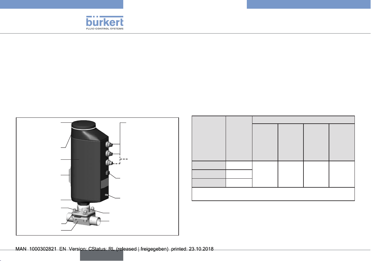
5.1 Structure of the electromotive diaphragm control valve
Dummy cover or
display with illumi-
nated display and
bayonet catch
Actuator cover
Actuator housing
Transparent
window with
position indicator
Actuator base
Bore for monitoring
leaks
Diaphragm
Valve body
Fig. 1: Structure, electromotive diaphragm control valve
Electrical connections (circular
plug-in connector
or cable gland)
Applies only to devices
with process controller
function
Pressure compensation element! Do not
unscrew!
FE functional ground
Diaphragm socket
Line connector
5.2 Display of the device state
To indicate device status and valve position, different LED modes can
be set (for description see main instructions).
LED mode set at the factory: “Valve mode w/ warnings”.
5.2.1 Displays in valve mode w/ warnings
When device status “Normal”: Permanently lit in the color of the valve
position.
If device status deviates from “Normal”: The colors for valve position
and device status flash alternately.
Valve
position
open
between
closed
* Factory setting; colors can be changed (see software description with
reference to Type 3363 at www.burkert.com).
Tab. 1: Display of device state in valve mode w/ warnings
If several device statuses exist simultaneously, the device status with
the highest priority is displayed.
The priority is determined by the severity of the deviation from standard
operation (red = failure = highest priority).
Color
Color of device status
of valve
position
Failure, error
or fault
Function
check
Out of
specification
Maintenance
yellow* red orange yellow blue
white
green*
requirement
8
Type 3363, 3364, 3365
english
Technical data
6 TECHNICAL DATA
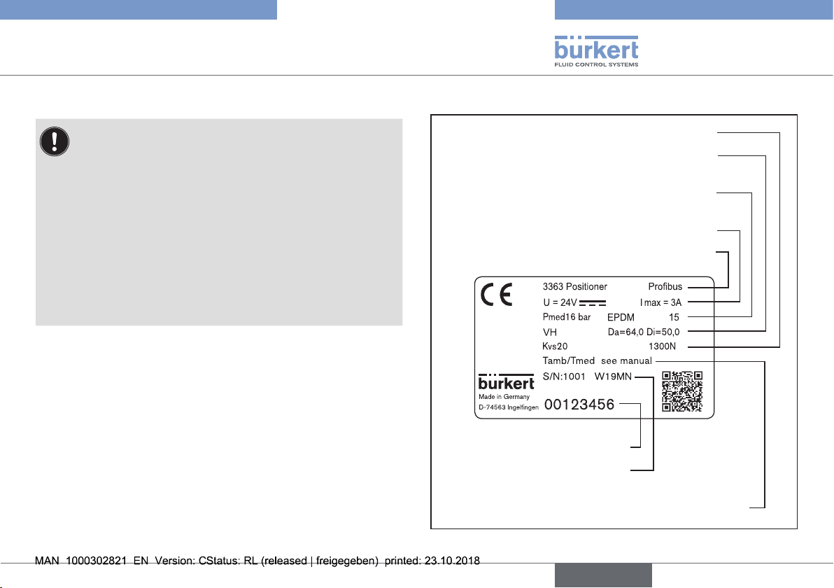
The following product-specific information is indicated on the rating plate:
• Voltage [V] (tolerance ±10%) and current type
• Diaphragm material and material of the valve body
• Fieldbus standard
• Diaphragm size
• Flow capacity
• Actuator size
• Line connector
• Maximum permitted medium pressure
6.1 Conformity
The electromotive diaphragm control valves Type 3363, 3364 and
3365 are compliant with EU directives as stated in the EU Declaration
of Conformity.
6.2 Standards
The applied standards, which are used to demonstrate compliance
with the EU Directives, are listed in the EU type test certificate and/or
the EU Declaration of Conformity.
6.3 Licenses
The product is cULus-approved. For notes on operation in the UL area,
see the chapters below.
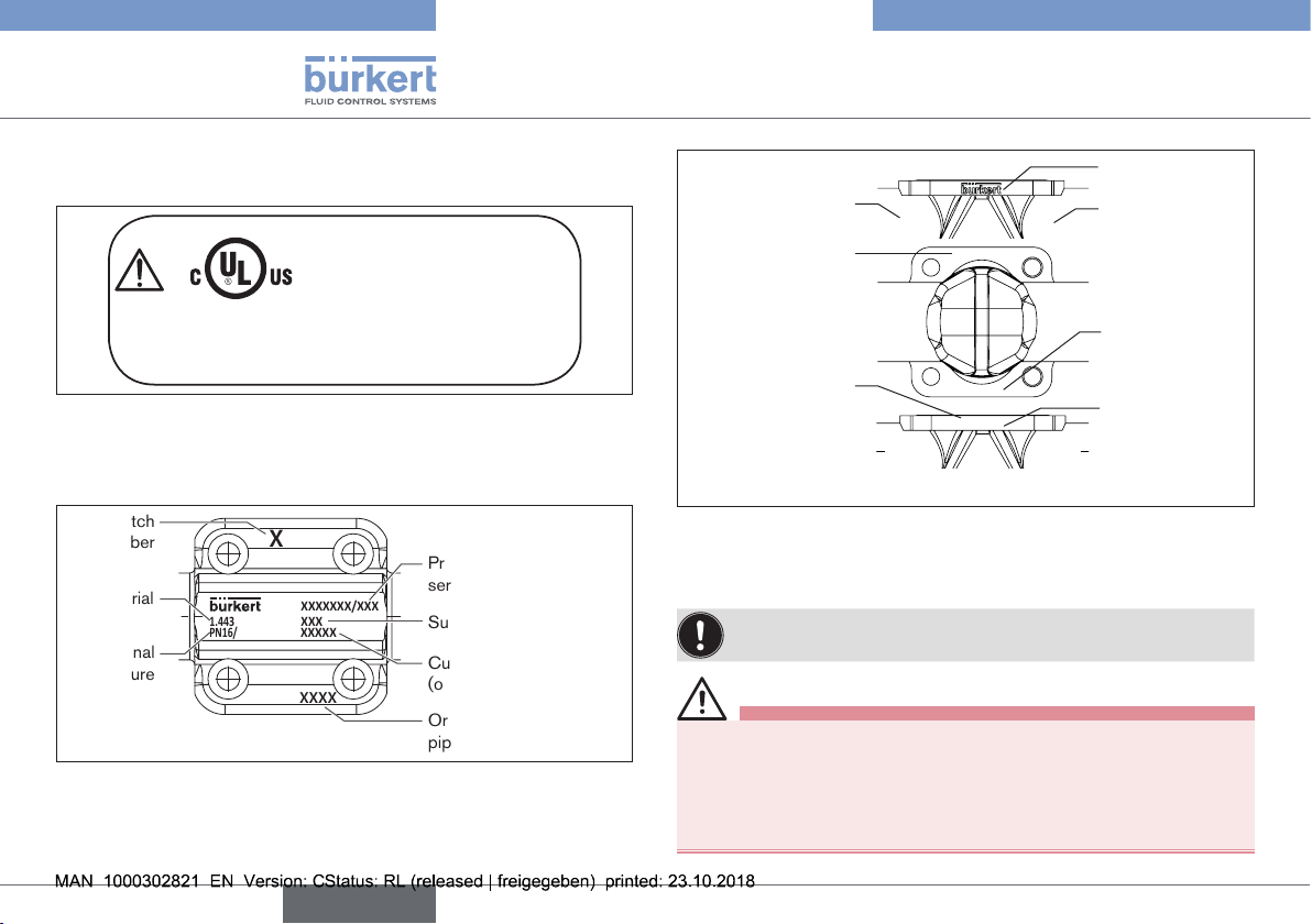
6.4 Rating plate
Flow capacity
line connection Da (ø outer) Di (ø inner)
Maximum permitted medium pressure, diaphragm
Voltage, direct current, maximum current
Type, function (position controller / process
Identification number of the device
date of manufacture (encoded)
Permitted temperature range (environment/medium)
Fig. 2: Description of the rating plate (example)
, actuator size (nominal force)
Material valve body,
material, diaphragm size
controller), fieldbus standard
Serial number,
9
Type 3363, 3364, 3365
english
Technical data
6.4.1 UL aAdditional type label for UL
approval (example)
Type AE3363
Power Supply
LISTED
Process Control Equipment
Fig. 3: Additional type label for UL approval (example)
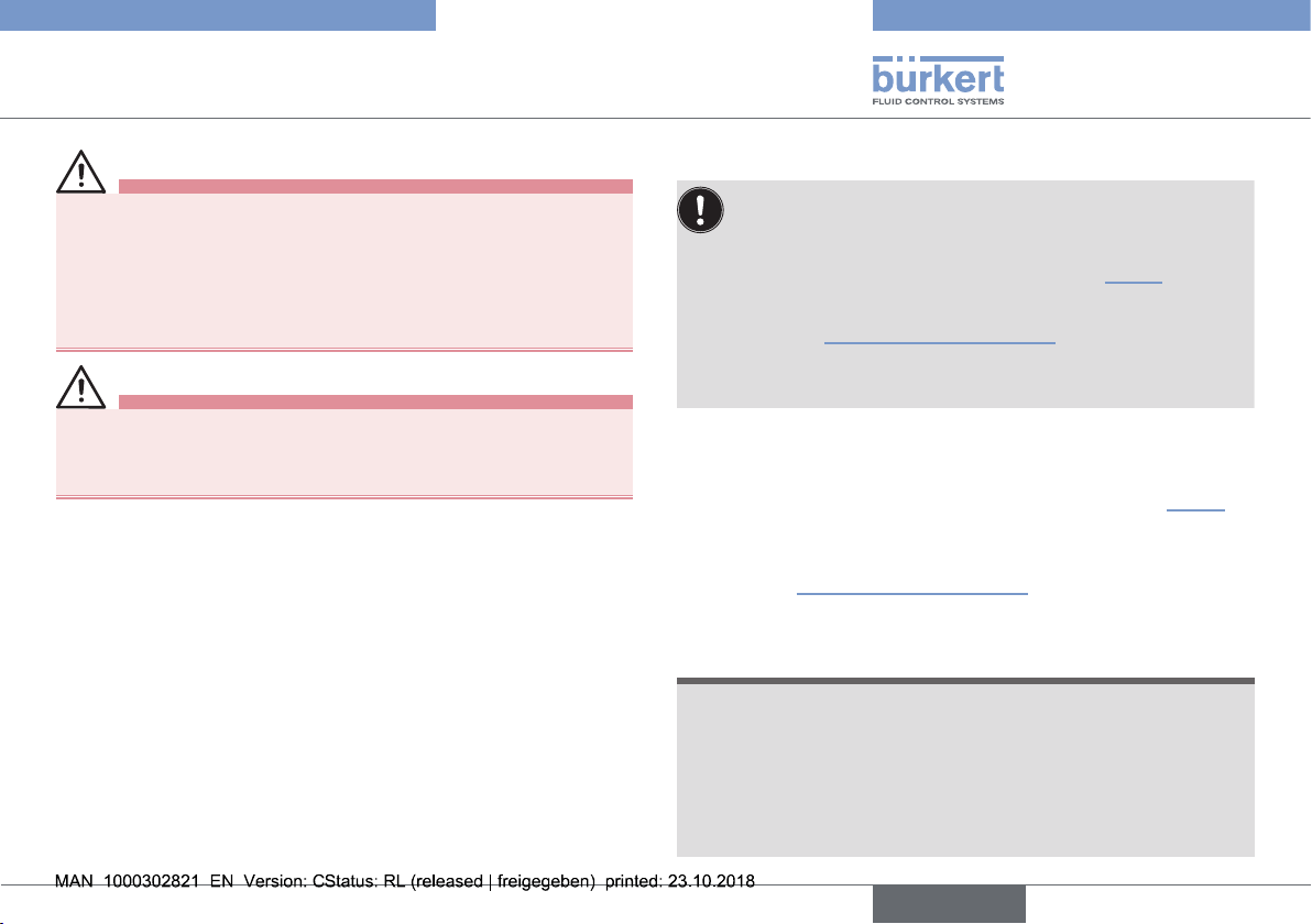
6.5 Labeling of the bodies
Batch
number
Material
Nominal
pressure
Fig. 4: Labeling of the forged bodies
E238179
1.4435/316L(VS)
PN16/CWP150
XXXXXXXXXX
XX F
SELV / PELV only!
Production number /
XXXXXXXX/XXX
XXXX
XXXXXX
serial number
Surface quality code
Customer-specific text
(optional)
Orifice connection and
pipe dimension
Company logo
Material
Nominal pressure
1.4435
316L(VP)
XXXXXXXX
PN16 / CWP150
Heat
Orifice
connection and
Production number
order number / Serial
number
XXXXXXXXXX
XXXXXXXX / XXX
XXXX / XXXXXX
pipe dimension
Surface quality
code / Customerspecific text
(optional)
Fig. 5: Labeling on the tubular-formed bodies (VP)
6.6 Operating conditions
For operation of the device observe the product-specific
information on the rating plate.
WARNING!
Malfunction if the temperature exceeds or drops below the
permitted temperature range.
▶ Never expose the device outdoors to direct sunlight.
▶ The temperature must not exceed or drop below the permitted
ambient temperature range.
10
Type 3363, 3364, 3365
english
Technical data
WARNING!
Reduced sealing function if medium pressure too high.
As the diaphragm control valve is closed against the medium flow,
the medium pressure may become too high and prevent the valve
from closing tightly.
▶ The medium pressure must not be greater than the maximum
value specified on the type label.
WARNING!
Danger due to escape of hot medium.
The diaphragm is not permanently temperature-resistant to hot medium.
▶ Do not use the diaphragm control valve for steam shut-off.
Maximum permitted medium pressure: see rating plate
Media: neutral, high-purity, sterile,
contaminated, aggressive or abrasive media
with high to semi-fluid viscosity.
Degree of protection: (veried by Bürkert / not evaluated by UL)
IP65 as per IEC 529, EN 60529
(IP67 on request).
NEMA 250 4x
Operating altitude: up to 2000 m above sea level.
6.6.1 Permitted temperature ranges
The permitted medium and ambient temperature ranges
depend on various factors:
Medium temperature: depends on the material of the valve
body and diaphragm materials. See chapter “6.6.2”.
Ambient temperature: depends on the medium temperature. See “Fig. 7: Temperature graph”.
To determine the permitted temperatures, all factors must be
taken into account.
Minimum temperatures
Environment: –10 °C (14 °F)
Medium: Observe dependence on material of the valve
body and diaphragm materials. See “6.6.2”.
Maximum temperatures
Observe dependencies on ambient temperature and medium temperature. See “Fig. 7: Temperature graph”.
6.6.2 Permitted medium temperature
ATTENTION!
The behavior of the medium with respect to the diaphragm materials may change depending on the medium temperature.
▶ The indicated medium temperatures apply only to media which
do not corrode or swell the diaphragm materials.
▶ The functional properties, and the life time of the diaphragm,
may be impaired if the temperature rises or drops below the
indicated medium temperature.
11
Type 3363, 3364, 3365
DN 15 - 40
10
20 40 60
80
100 120
140
english
Technical data
Permitted medium temperature for diaphragm materials
Diaphragm
material
EPDM (AB), PTFE/
Permitted medium temperature range
minimal maximal
Steam sterilisation
-10 °C +130 °C +140 °C/60 min.
EPDM (EA)
EPDM (AD)
-5 °C +143 °C +150 °C/60 min.
,advanced PTFE/
EPDM (EU)
GYLON / EPDM
-5 °C +130 °C +140 °C/60 min.
laminated (ER)
FKM (FF) 0 °C +130 °C No steam / dry heat
up to +150 °C/60
min.
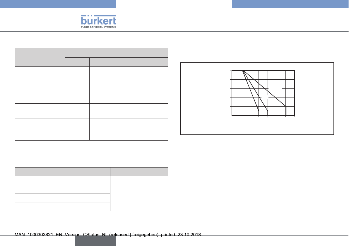
Tab. 2: Permitted medium temperature depending on the diaphragm
materials
Permitted medium temperature for valve bodies made of metal
Valve body material Temperature range
Stainless steel -10...+150 °C
Cast body (VG)
Forged body (VS)
Tubular-formed body (VP)
Tab. 3: Medium temperature for valve bodies
Permitted medium temperature for valve bodies made of plastic
The permitted medium temperature for valve bodies made of plastic
depends on the medium pressure.
8
6
4
PVC
2
PVDF
PP
Medium pressure [bar]
Temperature [°C]
Fig. 6: Graph: Medium temperature and medium pressure for valve
bodies made of plastic
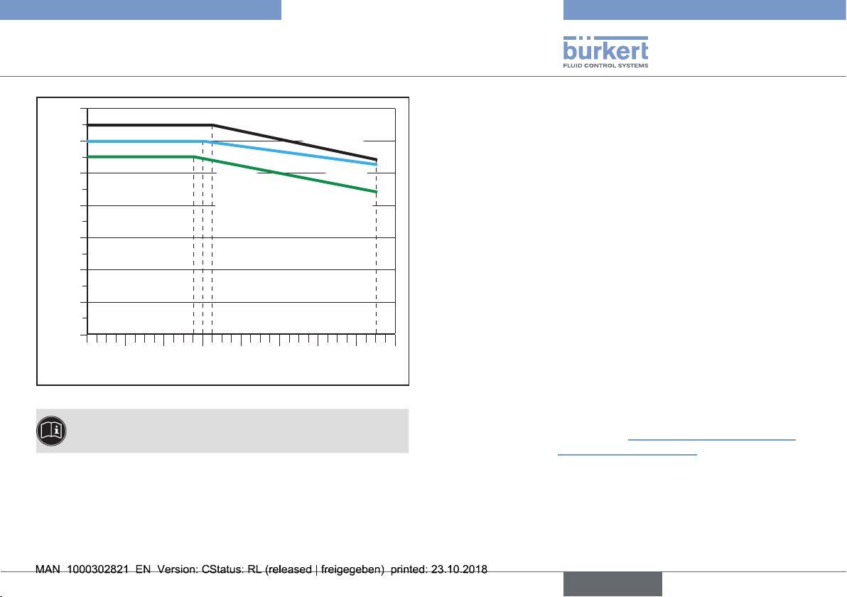
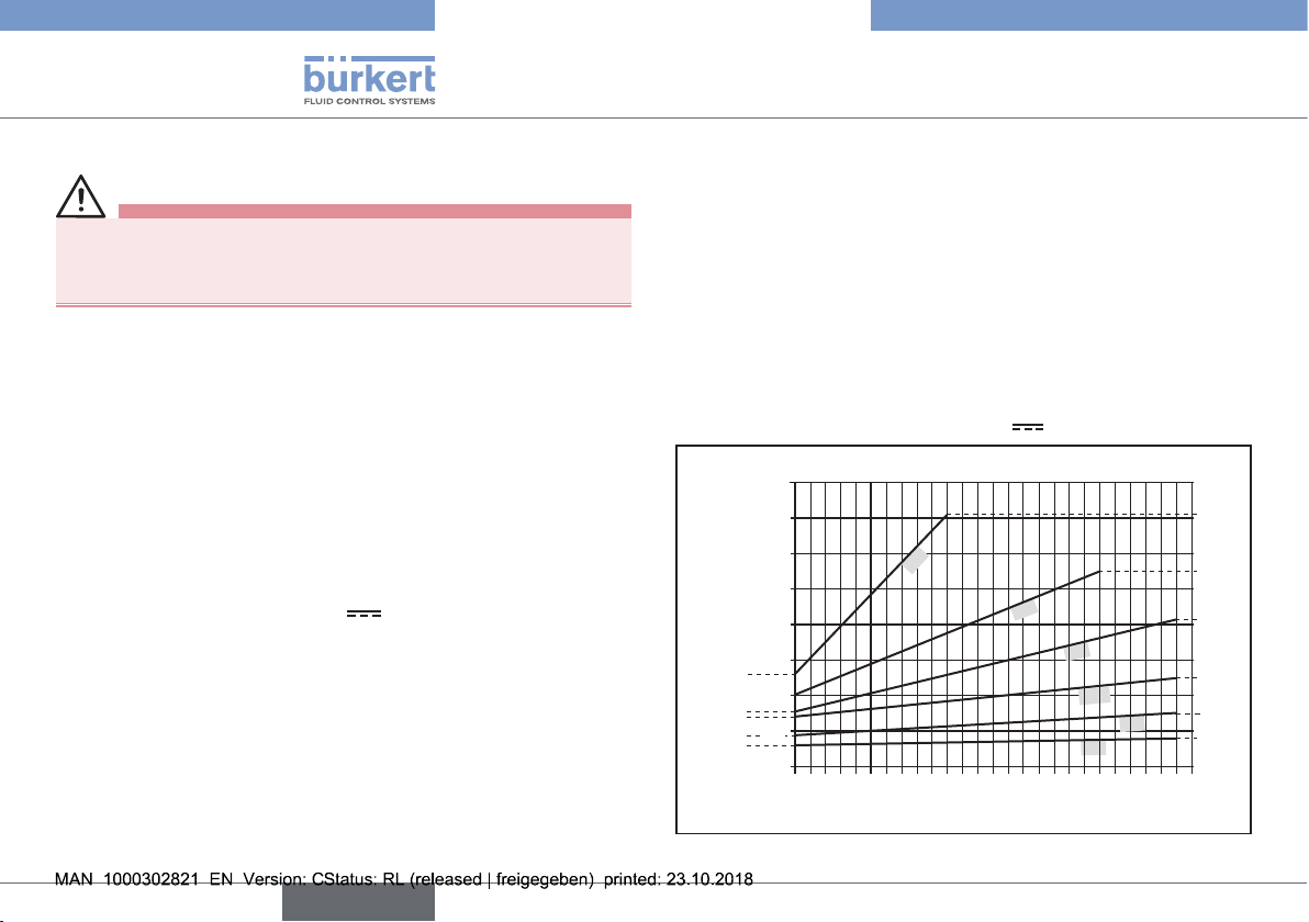
Temperature graph
The maximum permitted temperature for the environment and the
medium depend on each other. The permitted maximum temperatures
must be determined using the temperature graph. The values were
determined under the following maximum operating conditions: Diaphragm size 25 when 100% duty cycle at 10 bar medium pressure.
For deviating operating conditions an individual verification can be
performed. Please contact your Bürkert office for more information.
12
Type 3363, 3364, 3365
english
Technical data
70
60
50
40
30
20
Ambient temperature [°C]
10
0
0 20 60 100 14040 80 120 160
Medium temperature [°C]
Fig. 7: Temperature graph
* Service life of the SAFEPOS energy-packs depends on the
medium temperature and the ambient temperature (see chapter
Electrical data).
Devices without display module
Devices with display module
Devices with SAFEPOS energypack* or fieldbus gateway, with
or without display module
6.7 General technical data
Materials
Actuator: PPS and aluminum powder-coated
Valve body Metal: Investment casting (VG), forged steel
(VS), tubular-formed body (VP),
Plastic: PP, PVC and PVDF
Body connection: CF-8 / 1.4308
Spindle seal: FKM
Seal material: sealing element actuator housing: EPDM
Diaphragm: EPDM, PTFE or FKM (see type label)
Fluid connection:
Connection types: Welded connection according to EN ISO
1127 (ISO 4200), DIN 11850 Series 2.
Socket connection, clamp connection, flanged
connection, bonded connection.
Electrical connection: by connection terminals or circular plugs
Installation position: depends on the body model.
See chapter “7.1 Installation position of the
diaphragm control valves”
13
Type 3363, 3364, 3365
english
Technical data
6.7.1 Electrical data
DANGER!
Electric shock.
Protection class III is only guaranteed when using a SELV
power supply unit or PELV power supply unit.
Protection class: 3 in accordance with DIN EN 61140
(VDE 0140)
Electrical connections
Devices with
position controller function: cable gland, 2x M20 or
2 circular plug-in connectors M12,
5-pin and 8-pin
Devices with
process controller function: cable gland, 3x M20 or
circular plug-in connectors 2x M12,
5-pin and 1x M12, 8-pin
Operating voltage: 24 V ± 10%
max. residual ripple 10%
Operating current [A]**
: max. 3 A, including actuator at max.
load and charging current of the
optional SAFEPOS energy-pack
(charging current approx. 1 A) for the
design of the power supply unit
Supply voltage transmitter:
24 V ±10 %
available only for devices with process
controller function.
Supply current transmitter:
Max. 150 mA, available only for devices
with process controller function.
Standby consumption [W]**:
min. 2 W, max. 5 W
Average consumption [W]**
Electronics without actuator standard consumption: typically 3 W
Option analog and binary outputs: 0.5 W
SAFEPOS energy-pack: 0.5 W
Fieldbus gateway: 1 W
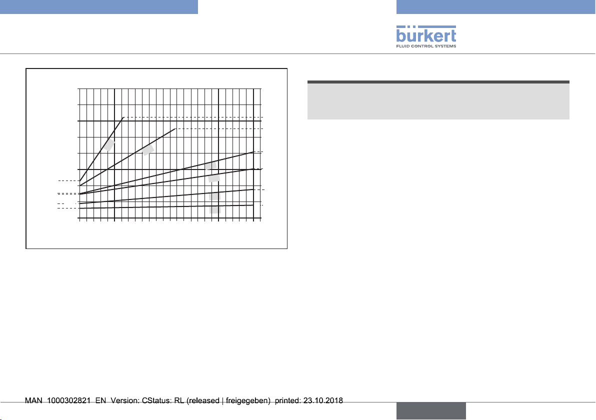
Energy consumption actuator for 1 cycle [Ws]**
(see following graphs)
** All values refer to a supply voltage of 24 V at 25 °C.
EPDM for each diaphragm size
160
140
120
40
141
110
100
80
60
52
40
32
27
20
Energy for 1 cycle in [Ws]
18
13
32
25
20
15
08
82
52
29
18
0
0 2 4 6
8
10
Medium pressure in [bar]
Fig. 8: Energy consumption of actuator for each diaphragm size, EPDM
14
Type 3363, 3364, 3365
english
Technical data
PTFE for each diaphragm size
160
140
120
125
110
100
80
40
60
46
40
30
29
20
Energy for 1 cycle in [Ws]
18
13
32
25
20
15
08
82
61
35
18
0
0 2 4 6
8
10
Medium pressure in [bar]
Fig. 9: Energy consumption of actuator for each diaphragm size, PTFE
SAFEPOS energy-pack: Charging time: maximum 100 seconds
(depending on the conditions of use)
Service life: Up to 10 years (depending
on the conditions of use). The determined
service life of 7.5 years was determined
under the following conditions:
Ambient temperature 30 °C
Medium temperature 80 °C
Duty cycle 100 %
Medium pressure 6 bar
Diaphragm size 32
ATTENTION!
Consider voltage drop in supply line.
For example, a cable cross-section of 0.34 mm
2
must not exceed
a line length of 8 meters for a copper cable.
Analog inputs: (galvanically isolated from the supply
voltage and analog output)
Input data for setpoint value signal
0/4...20 mA: Input resistance 60 Ω
Resolution 12 bits
0...5/10 V: Input resistance 22 kΩ
Resolution 12 bit, resolution with
regard to 0...10 V
Input data for actual
value signal (optional)
4...20 mA: Input resistance 60 Ω
Resolution 12 bits
Frequency: Measuring range 0.2...6500 Hz
Input resistance > 30 kΩ
Precision 0.1 % of measured value
Input signal > 300 mVss
Waveform Sine wave, rectangle
wave, triangle wave
Pt 100: Measuring range –20...+220 °C
Precision 0.01 °C
Measurement
1 mA
current
15
Type 3363, 3364, 3365
english
Installation of the valve
Analog output
(optional)
Max. current:
Burden (load): 0...800 Ω (for current output 0/4...20 mA)
Digital outputs
(optional)
Current limit: 100 mA,
Digital inputs:
Communications
interface:
Communications
software:
The digital input, the digital outputs and the analog output are
not galvanically isolated for the operating voltage. They refer
to the GND potential of the operating voltage.
Current limit: in the event of an overload the output voltage is
reduced.
10 mA (for voltage output 0...5/10 V)
0...5 V = log "0", 10...30 V = log "1"
inverted input reversed accordingly (input
current < 6 mA)
Connection to PC with USB büS interface
set
Bürkert-Communicator
7 INSTALLATION OF THE VALVE
WARNING!
Risk of injury from improper assembly.
▶ The assembly may be carried out only by trained technicians
and with the appropriate tools.
▶ Secure system against unintentional activation.
▶ After installation, ensure that the process is restarted in a con-
trolled manner. Observe sequence!
1. Apply supply voltage.
2. Charge the device with medium.
CAUTION!
Risk of injury due to a heavy device.
A heavy device can fall down during transport or during installation
and cause injuries.
▶ Transport, install and dismantle a heavy device with the help of
another person.
▶ Use appropriate tools.
NOTE!
Note the following when installing the device in the plant.
The device and the relief bore must be accessible to allow inspection
and maintenance work.
16
Type 3363, 3364, 3365
english
Installation of the valve
7.1 Installation position of the diaphragm control valves
The installation position of the diaphragm control valve varies
depending on the valve body.
One of the bores in the diaphragm socket, for monitoring
leakage, must be at the lowest point.
7.1.1 Installation position of 2-way body
Installation position: any position, preferably with the actuator
facing up.
Ensuring self-drainage:
→ Install valve body at an angle α = 10° – 40° inclined towards the
horizontal.
This is indicated by a mark on forged and cast bodies which
must face upwards (12 o’clock position, see “Fig. 10”).
Marking
α
Angle α: 10° – 40°
Fig. 10: Installation position for self-drainage of the body
→ Observe an inclination angle of 1° – 5° for the pipeline.
It is the responsibility of the installer and operator to ensure
self-drainage.
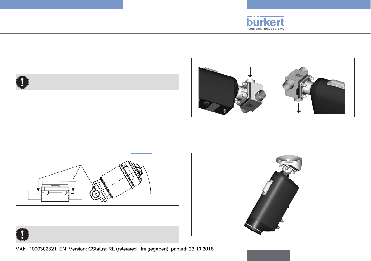
7.1.2 Installation position of T-body
Installation position:
For supply of a medium: For removal of a medium:
Fig. 11: Installation position of Type 3364
7.1.3 Installation position of tank bottom body
Recommended installation position: any, preferably with actuator
face down.
Fig. 12: Installation position of tank bottom body, Type 3365
17
Type 3363, 3364, 3365
english
Installation of the valve
7.2 Installation of devices with socket connection, flanged connection, clamp connection or bond connection
ATTENTION!
Damage to the diaphragm.
▶ To prevent damage, the valve must be in MANUAL operating
state during installation.
Devices are delivered with the MANUAL operating state preset.
Installation requirements:
Pipelines: Ensure that the pipelines are aligned.
Preparation: Support and align pipelines. To ensure that the pipeline
is self-draining, observe an inclination angle of 1° – 5°.
DANGER!
Risk of injury from high pressure.
▶ Before working on the system, switch off the pressure and vent
or drain lines.
→ Connect valve body to pipeline.
Ensure installation is de-energized and low-vibration.
Holding device
To protect the valve actuator from damage due to forces
and vibrations, a holding device is recommended. This is
available as an accessory. See operating instructions on the
Homepage www.burkert.com
→ Connect the device electrically.
The position of the connections can be aligned by rotating
the actuator through 360°. For a description see chapter “7.5
Rotating the actuator”.
A description of the electrical connection can be found in
chapter “8 Electrical installation”.
7.2.1 Following installation
→ When the operating voltage has been applied, make the required
basic settings and adjustments for the electromotive diaphragm
control valve. For a description see chapter “9 Start-up”.
ATTENTION!
Damage to the diaphragm.
▶ To prevent damage, first run the M.Q0.TUNE function after mak-
ing the electrical connection. Only then set the operating state
to AUTOMATIC.
7.3 Installation of devices with welded connection
ATTENTION!
Observe the national regulations for the qualification of welders
and for performing welding work.
Damage to the diaphragm.
▶ Weld the device into the pipeline only with the actuator
removed.
▶ To prevent damage, the device must be in MANUAL operat-
ing state during installation. The actuator must be in the “Valve
open” position.
18
 Loading...