

Page 1
Operating Instructions
Bedienungsanleitung
Manuel d‘utilisation
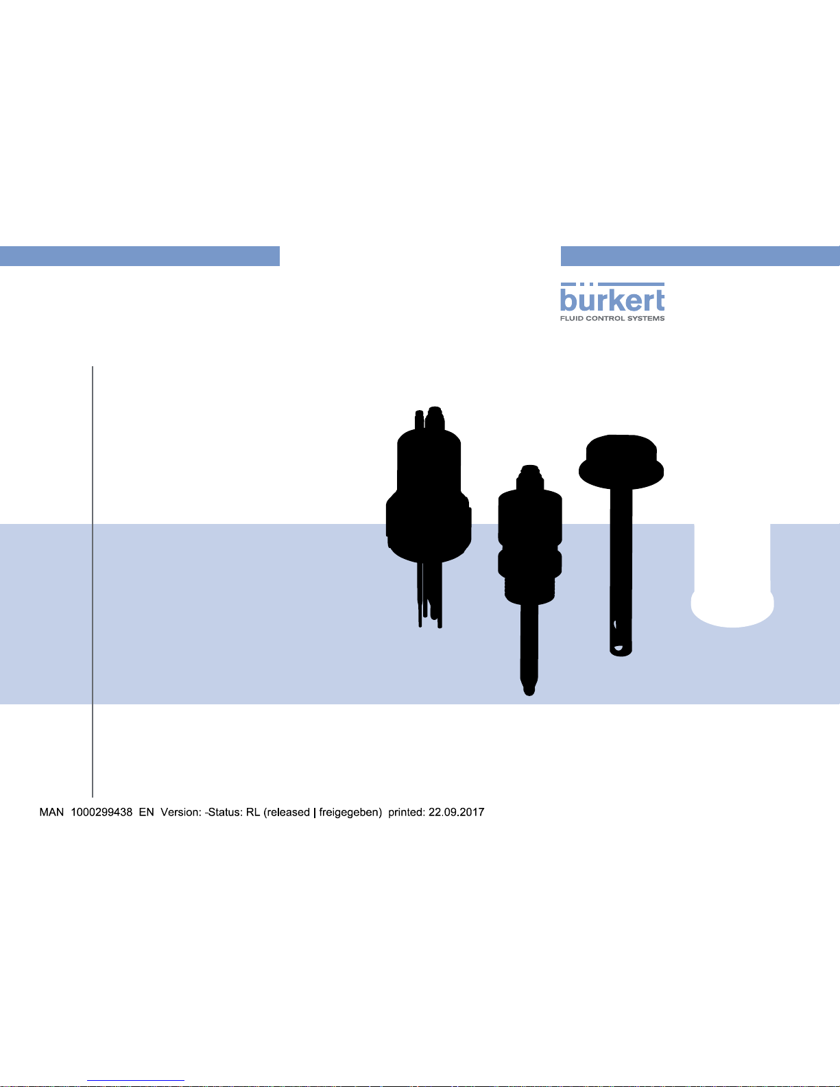
Type 8200
Probe Holder
Sondenhalter
Support de sonde d’analyse
Page 2

We reserve the right to make technical changes without notice.
Technische Änderungen vorbehalten.
Sous réserve de modifications techniques.
© Bürkert SAS, 2013-2016
Operating Instructions 1608/01_EU-ML_00564990 / Original_FR
Page 3
3
Contents
Type 8200
1. ABOUT THESE OPERATING INSTRUCTIONS ...............................4
1.1. Symbols used ......................................................................................4
1.2. Definition of the word "holder" ....................................................4
2. INTENDED USE ................................................................................................5
3. BASIC SAFETY INFORMATION ....................................................................5
4. GENERAL INFORMATION ..........................................................................6
4.1. Manufacturer's address and international contacts ........6
4.2. Warranty conditions .......................................................................... 6
4.3. Information on the Internet ............................................................6
5. TECHNICAL DATA ..........................................................................................7
5.1. Conditions of use ..............................................................................7
5.2. Dimensions ...........................................................................................7
5.3. Mechanical data ................................................................................... 7
6. INSTALLATION, COMMISSIONING .......................................................9
6.1. Safety instructions ............................................................................9
6.2. Installation of a 8200 G2" version onto an S020
fitting ...................................................................................................... 10
6.3. Installation of a 8200 G1" version onto a Tee fitting ... 10
6.4. Installation of a stick connection 8200 onto a
Tee fitting ............................................................................................ 10
6.5. Installation of a 8200 clamp version .................................... 11
6.6. Installation of a 8200 for DN50 thread process
connection ..........................................................................................11
7. MAINTENANCE AND CLEANING ........................................................12
7.1. Safety instructions ......................................................................... 12
7.2. Cleaning ............................................................................................... 12
8. PACKAGING, TRANSPORT AND STORAGE .................................13
9. DISPOSAL OF THE PRODUCT ............................................................ 13
English
Page 4
4
About these Operating Instructions
Type 8200
1. ABOUT THESE OPERATING
INSTRUCTIONS
These Operating Instructions describe the entire life cycle of the
probe holder. Please keep these Operating Instructions in a safe
place, accessible to all users and any new owners.
Important safety information.
Failure to comply with these instructions can lead to hazardous
situations. Pay attention in particular to the chapters 3. Basic
safety information and 2. Intended use.
▶ Whatever the version of the device, these Operating Instructions
must be read and understood.
1.1. Symbols used
Danger
Warns against an imminent danger.
▶ Failure to observe this warning can result in death or in serious
injury.
Warning
Warns against a potentially dangerous situation.
▶ Failure to observe this warning can result in serious injury or even
death.
attention
Warns against a possible risk.
▶ Failure to observe this warning can result in substantial or minor
injuries.
note
Warns against material damage.
Indicates additional information, advice or important
recommendations.
Refers to information contained in these Operating Instructions or in other documents.
▶ Indicates an instruction to be carried out to avoid a danger, a
warning or a possible risk.
→ Indicates a procedure to be carried out.
Indicates the result of a specific instruction.
1.2. Definition of the word "holder"
The word "holder" used within these Operating Instructions refers to
the probe holder type 8200.
English
Page 5
5
Intended use
Type 8200
2. INTENDED USE
Use of the probe holder that does not comply with the
instructions could present risks to people, nearby installations and the environment.
The 8200 probe holder allows to install an analytical probe on a
Bürkert S020 fitting or on a Tee fitting available on the market.
▶ Use the holder in compliance with the specifications and
conditions of commissioning and use given in the contractual
documents, in these operating instructions and in the operating
instructions for the device which is inserted into the holder.
▶ Safe and trouble-free operation of the holder depends on its
proper transport, storage and installation, as well as careful
operation and maintenance.
▶ Only use the holder as intended.
3. BASIC SAFETY INFORMATION
This safety information does not take into account:
• any contingencies or occurrences that may arise during installation, use and maintenance of the devices.
• the local safety regulations for which the operating company
is responsible including the staff in charge of installation and
maintenance.
Danger due to high pressure in the installation.
Danger due to high temperatures of the medium.
Danger due to the nature of the medium.
Various dangerous situations.
To avoid personal injury, take care to:
▶ Prevent any unintentional power supply switch-on.
▶ Ensure that installation and maintenance work are carried out by
qualified, authorised personnel in possession of the appropriate
tools.
▶ Guarantee a set or controlled restarting of the process, after a
power supply interruption.
▶ Use the holder only if in perfect working order and in compliance
with the instructions provided in the Operating Instructions.
English
Page 6

6
General information
Type 8200
Various dangerous situations (continued).
To avoid personal injury, take care:
▶ To observe the general technical rules when installing and using
the holder.
▶ Not to use the holder in explosive atmospheres.
▶ Not to use medium that is incompatible with the materials from
which the holder is made.
▶ Not to use the holder in an environment incompatible with the
materials from which it is made.
▶ Not to subject the holder to mechanical loads.
▶ Not to paint the internal or external threaded parts.
note
The holder may be damaged by the medium in contact with.
▶ Systematically check the chemical compatibility of the compo-
nent materials of the holder and the media likely to come into
contact with it (for example: alcohols, strong or concentrated
acids, aldehydes, alkaline compounds, esters, aliphatic com-
pounds, ketones, halogenated aromatics or hydrocarbons,
oxidants and chlorinated agents).
4. GENERAL INFORMATION
4.1. Manufacturer's address and
international contacts
To contact the manufacturer of the holder, use following address:
Bürkert SAS
Rue du Giessen
BP 21
F-67220 TRIEMBACH-AU-VAL
The addresses of our international sales offices are available on the
internet at: www.burkert.com
4.2. Warranty conditions
The condition governing the legal warranty is the conforming use
of the 8200 in observance of the operating conditions specified in
these Operating Instructions.
4.3. Information on the Internet
You can find the Operating Instructions and technical data sheets
regarding the type 8200 at: www.burkert.com
English
Page 7

7
Technical data
Type 8200
5. TECHNICAL DATA
5.1. Conditions of use
Medium
temperature
depends on the inserted probe and the fitting used.
Refer to the relevant operating instructions. If the
temperature ranges are different, use the most
restrictive range.
Pressure
class
depends on the inserted probe and the fitting
used. Refer to the relevant operating instructions.
If the pressure ranges are different, use the most
restrictive range.
5.2. Dimensions
→ Please refer to the technical data sheets regarding the probe
holder type 8200, available at: www.burkert.com
5.3. Mechanical data
Type of holder Process connection
For general purpose
(not hygienic)
• G2": with insertion fitting type S020
• G1": with Tee fitting available on the
market
• Stick: with Tee fitting d32xd32 up to
d32xd110
Hygienic • Clamp 1½", Ø 50,5 mm (ISO 2852)
• Clamp 2", Ø 64 mm (ISO 2852)
• For DN50 thread process connection
(SMS 1145)
English
Page 8

8
Technical data
Type 8200
Tab. 1 : Characteristics of the holders
Type of connection Material Medium temperature Medium pressure
Frame Seal
For general purpose
G2" Stainless steel
(316L / 1.4404),
PVC
FKM
(EPDM on
request)
• With S020 PVC fitting:
0...+50°C
• With S020 PVC fitting:
PN10
• Stainless steel:
–20...+130°C
• Stainless steel:
PN16
G1" or stick connection PVC FKM 0...+50°C PN10
Hygienic
Clamp 1½"
Insertion depth: 117 mm
Stainless steel
(316L / 1.4404)
FKM –10...+135°C PN6
• Clamp 2"
• For DN50 thread
process connection
Stainless steel
(316L / 1.4404)
EPDM –10...+140°C PN16
English
Page 9

9
Installation, commissioning
Type 8200
6. INSTALLATION,
COMMISSIONING
6.1. Safety instructions
Danger
Risk of injury due to high pressure in the installation.
▶ Stop the circulation of medium, cut-off the pressure and drain
the pipe before loosening the process connections.
Risk of injury due to high medium temperatures.
▶ Use safety gloves to handle the holder.
▶ Stop the circulation of medium and drain the pipe before loos-
ening the process connections.
Risk of injury due to the nature of the medium.
▶ Respect the prevailing regulations on accident prevention and
safety relating to the use of hazardous products.
Warning
Risk of injury if the holder is not tight.
▶ Make sure that a probe is inserted in every hole to ensure the
tightness of the holder.
Warning
Risk of injury due to nonconforming installation.
▶ Installation can only be carried out by qualified and authorised
personnel with the appropriate tools.
▶ Observe the installation instructions for the measuring device
inserted into the holder.
Risk of injury due to an uncontrolled restart.
▶ Ensure that the restart of the installation is controlled after any
interventions on it.
Warning
Danger due to nonconforming commissioning.
Nonconforming commissioning may lead to injuries and damage
the holder and its surroundings.
▶ Before commissioning, make sure that the staff in charge
have read and fully understood the contents of the Operating
Instructions.
▶ In particular, observe the safety recommendations and intended
use.
▶ The installation must only be commissioned by suitably trained
staff.
English
Page 10

10
Installation, commissioning
Type 8200
6.2. Installation of a 8200 G2" version
onto an S020 fitting
Make sure the S020 fitting used for the installation of a G2"
holder is a special fitting for analysis (see the data sheets of
the S020 fitting).
Fit the fitting at an angle of ±75° max. to the vertical in order
to ensure the good operation of the pH/redox probe.
→ Install the fitting in compliance with the instructions provided in
the Operating Instructions.
2
1
3
4
5
→ Check that the seal is on the fitting and
that it is not damaged.
Replace it if necessary.
→ Unscrew the nut 2 from the holder.
→ Insert the nut 2 on the fitting S020,
identified 5.
→ Insert the snap ring 3 in the groove 4.
→ Check that the seal 1 is correctly
inserted in the holder.
→ Place the holder onto the fitting.
→ Screw the nut 2 to the holder to fix it to
the fitting.
→ Insert the probes in the corresponding
holes.
Fig. 1 : Installation of a G2" holder
6.3. Installation of a 8200 G1" version
onto a Tee fitting
G1"
d
→ Check that the seal is on the holder.
→ Screw the G1" holder onto the Tee
fitting.
→ Insert the probes in the corresponding
holes.
Fig. 2 : Installation of a G1" holder
6.4. Installation of a stick connection
8200 onto a Tee fitting
Ø 32
d
→ Stick the 8200 PVC-U holder onto
a PVC-U Tee fitting with appropriate
dimensions.
→ Insert the probes in the corresponding
holes.
Fig. 3 : Installation of a stick holder
English
Page 11

11
Installation, commissioning
Type 8200
6.5. Installation of a 8200 clamp version
Clamp 1½" Clamp 2"
117
→ Check that the seal is on the holder.
→ Install the clamp holder onto the clamp of the pipe.
→ Only for version Clamp 1½", observe the 117 mm of the
insertion depth.
→ Place the clamps together.
→ Fix the clamps with the flange clamp.
→ Insert the probes in the corresponding holes.
Fig. 4 : Installation of a clamp holder
6.6. Installation of a 8200 for DN50
thread process connection
1
2
3
a
b
→ On the pipe, install a DN50 spigot
(not provided by Bürkert), compatible with SMS 1145 and place
a seal (not provided by Bürkert) if
necessary.
→ Place the probe holder 1 onto the
spigot 2.
→ Screw the nut 3 (not provided by
Bürkert) to the holder to fix it to the
spigot.
→ Insert the probes in the corre-
sponding holes.
a. Pt1000 temperature probe
b. Analytical probe
Fig. 5 : Installation of a probe holder type 8200 for DN50 thread
process connection (acc. to SMS 1145)
English
Page 12

12
Maintenance and cleaning
Type 8200
7. MAINTENANCE AND
CLEANING
7.1. Safety instructions
Danger
Risk of injury due to high pressure in the installation.
▶ Stop the circulation of medium, cut-off the pressure and drain
the pipe before loosening the process connections.
Risk of injury due to high medium temperatures.
▶ Use safety gloves to handle the holder or the adapter.
▶ Stop the circulation of medium and drain the pipe before loos-
ening the process connections.
▶ Keep all easily flammable medium or material away from the
holder or the adapter.
Risk of injury due to the nature of the medium.
▶ Respect the prevailing regulations on accident prevention and
safety relating to the use of aggressive media.
Warning
Risk of injury due to nonconforming maintenance.
▶ Maintenance must only be carried out by qualified and skilled
staff with the appropriate tools.
▶ Ensure that the restart of the installation is controlled after any
interventions.
7.2. Cleaning
note
The holder may be damaged by the cleaning product.
▶ Clean the holder with a cloth dampened with water or a deter-
gent compatible with the materials the holder is made of.
8. SPARE PARTS AND
ACCESSORIES
attention
Risk of injury and/or damage caused by the use of unsuitable parts.
Incorrect accessories and unsuitable spare parts may cause
injuries and damage the holder and the surrounding area.
▶ Use only original accessories and original spare parts from Bürkert.
Accessory Order code
Set with FKM seals
429 264
Set with 1 green FKM + 1 black EPDM seal
552 111
English
Page 13

13
Packaging, transport and storage
Type 8200
9. PACKAGING, TRANSPORT
AND STORAGE
attention
Damage due to transport
Transport may damage an insufficiently protected part.
▶ Transport the holder in shock-resistant packaging and away
from humidity and dirt.
▶ Do not expose the holder to temperatures that may exceed the
admissible storage temperature range.
Poor storage can damage the holder.
▶ Store the holder in a dry place away from dust.
Storage temperature:
▶ G2" PVC: 0...+50°C
▶ G2" stainless steel: –20...+130°C
▶ G1": 0...+50°C
▶ Clamp 1½": –10...+135°C
▶ Clamp 2" (ISO 2852) or for DN50 thread process connection
(acc. to SMS 1145): –20...+140°C
10. DISPOSAL OF THE PRODUCT
→ Dispose of the holder and its packaging in an environmentally-
friendly way.
note
Damage to the environment caused by parts contaminated by
the medium
▶ Comply with the national and/or local regulations which concern
the area of waste disposal.
English
Page 14

14
Disposal of the product
Type 8200
English
Page 15

Page 16

www.burkert.com
 Loading...