

Page 1

093091
en
Page 2

Page 3

Table of contents
Table of contents
1 About this manual . . . . . . . . . . . . . . . . . . . . . . . . . . . . . . . . . . . . . . .5
1.1 Reference documents. . . . . . . . . . . . . . . . . . . . . . . . . . . . . . . . . .5
1.2 Trademarks . . . . . . . . . . . . . . . . . . . . . . . . . . . . . . . . . . . . . . . 5
1.3 Abbreviations . . . . . . . . . . . . . . . . . . . . . . . . . . . . . . . . . . . . . . 5
2 Safety. . . . . . . . . . . . . . . . . . . . . . . . . . . . . . . . . . . . . . . . . . . . . .6
2.1 User qualification . . . . . . . . . . . . . . . . . . . . . . . . . . . . . . . . . . . . 6
2.2 Proper use . . . . . . . . . . . . . . . . . . . . . . . . . . . . . . . . . . . . . . . 6
2.3 Improper use . . . . . . . . . . . . . . . . . . . . . . . . . . . . . . . . . . . . . . 6
2.4 Warning notices used in this manual . . . . . . . . . . . . . . . . . . . . . . . . . . 7
2.5 Product safety. . . . . . . . . . . . . . . . . . . . . . . . . . . . . . . . . . . . . .7
2.6 General safety rules . . . . . . . . . . . . . . . . . . . . . . . . . . . . . . . . . . . 8
3 Technical data . . . . . . . . . . . . . . . . . . . . . . . . . . . . . . . . . . . . . . . . . 9
3.1 Scope of delivery . . . . . . . . . . . . . . . . . . . . . . . . . . . . . . . . . . . . 9
3.1.1 Vacuum system . . . . . . . . . . . . . . . . . . . . . . . . . . . . . . . . . . . . . 9
3.1.2 Vacuum Controller. . . . . . . . . . . . . . . . . . . . . . . . . . . . . . . . . . . 10
3.1.3 Two controllers . . . . . . . . . . . . . . . . . . . . . . . . . . . . . . . . . . . . 12
3.1.4 Woulff bottle. . . . . . . . . . . . . . . . . . . . . . . . . . . . . . . . . . . . . . 12
3.1.5 Condensation assembly. . . . . . . . . . . . . . . . . . . . . . . . . . . . . . . . 13
3.2 Technical data overview . . . . . . . . . . . . . . . . . . . . . . . . . . . . . . . . 14
3.3 Materials used. . . . . . . . . . . . . . . . . . . . . . . . . . . . . . . . . . . . . 14
3.4 Solvent table . . . . . . . . . . . . . . . . . . . . . . . . . . . . . . . . . . . . . 15
4 Description of function . . . . . . . . . . . . . . . . . . . . . . . . . . . . . . . . . . . 16
4.1 Vacuum pump. . . . . . . . . . . . . . . . . . . . . . . . . . . . . . . . . . . . . 16
4.1.1 Functional principle . . . . . . . . . . . . . . . . . . . . . . . . . . . . . . . . . . 16
4.1.2 Front view . . . . . . . . . . . . . . . . . . . . . . . . . . . . . . . . . . . . . . . 16
4.1.3 Rear view . . . . . . . . . . . . . . . . . . . . . . . . . . . . . . . . . . . . . . . 17
4.1.4 Gas ballast . . . . . . . . . . . . . . . . . . . . . . . . . . . . . . . . . . . . . . 19
4.2 Vacuum Controller V-850/855 . . . . . . . . . . . . . . . . . . . . . . . . . . . . . 19
4.2.1 Control keys of Vacuum Controller V-850 . . . . . . . . . . . . . . . . . . . . . . . 19
4.2.2 Rear connections of the vacuum controller . . . . . . . . . . . . . . . . . . . . . . 20
4.3 Vacuum Module V-801 EasyVac. . . . . . . . . . . . . . . . . . . . . . . . . . . . 21
4.3.1 Front view EasyVac . . . . . . . . . . . . . . . . . . . . . . . . . . . . . . . . . . 22
4.3.2 Back view EasyVac . . . . . . . . . . . . . . . . . . . . . . . . . . . . . . . . . . 23
4.4 Vacuum Module V-802 Lab Vac . . . . . . . . . . . . . . . . . . . . . . . . . . . . 24
4.5 ECO2 Mode . . . . . . . . . . . . . . . . . . . . . . . . . . . . . . . . . . . . . . 25
Read this manual carefully before installing and running your system and note the safety precautions
in chapter 2 in particular. Store the manual in the immediate vicinity of the instrument, so that it can be
consulted at any time.
No technical modifications may be made to the instrument without the prior written agreement of
BUCHI. Unauthorized modifications may affect the system safety or result in accidents.
This manual is copyright. Information from it may not be reproduced, distributed, or used for competitive purposes, nor made available to third parties. The manufacture of any component with the aid of
this manual without prior written agreement is also prohibited.
The English manual is the original language version and serves as basis for all translations
into other languages. Other language versions can be downloaded at www.buchi.com.
3 V-700/710 Operation Manual, Version E
Page 4

Table of contents
4.6 Vacuum connections to the valve unit or Woulff bottle . . . . . . . . . . . . . . . . . 25
4.7 Connections to the secondary condenser . . . . . . . . . . . . . . . . . . . . . . . 26
4.8 Connections at the cold trap . . . . . . . . . . . . . . . . . . . . . . . . . . . . . 26
5 Putting into operation . . . . . . . . . . . . . . . . . . . . . . . . . . . . . . . . . . . . 27
5.1 Installation site. . . . . . . . . . . . . . . . . . . . . . . . . . . . . . . . . . . . . 27
5.2 Vacuum controller . . . . . . . . . . . . . . . . . . . . . . . . . . . . . . . . . . . 27
5.3 Electrical connections . . . . . . . . . . . . . . . . . . . . . . . . . . . . . . . . . 28
5.4 Silencer or secondary condenser . . . . . . . . . . . . . . . . . . . . . . . . . . . 29
5.4.1 Secondary condenser . . . . . . . . . . . . . . . . . . . . . . . . . . . . . . . . . 29
5.4.2 Silencer . . . . . . . . . . . . . . . . . . . . . . . . . . . . . . . . . . . . . . . . 30
5.5 Woulff bottle or valve unit . . . . . . . . . . . . . . . . . . . . . . . . . . . . . . . 30
5.6 Vacuum connection to the vacuum controller . . . . . . . . . . . . . . . . . . . . . 31
5.7 Complete system connection with one Rotavapor and one vacuum controller. . . . . 32
5.8 System pump with two controllers on two Rotavapor . . . . . . . . . . . . . . . . . 33
5.9 System pump with two controllers on one pump . . . . . . . . . . . . . . . . . . . 34
6 Operation . . . . . . . . . . . . . . . . . . . . . . . . . . . . . . . . . . . . . . . . . . 39
6.1 Starting the pump . . . . . . . . . . . . . . . . . . . . . . . . . . . . . . . . . . . 39
6.1.1 Pump without controller . . . . . . . . . . . . . . . . . . . . . . . . . . . . . . . . 39
6.1.2 Pump with controller . . . . . . . . . . . . . . . . . . . . . . . . . . . . . . . . . 39
6.1.3 EasyVac. . . . . . . . . . . . . . . . . . . . . . . . . . . . . . . . . . . . . . . . 39
6.1.4 LabVac . . . . . . . . . . . . . . . . . . . . . . . . . . . . . . . . . . . . . . . . 39
6.1.5 ECO2 Mode . . . . . . . . . . . . . . . . . . . . . . . . . . . . . . . . . . . . . . 39
6.2 Selecting the distillation conditions . . . . . . . . . . . . . . . . . . . . . . . . . . 40
6.3 Optimizing the distillation conditions. . . . . . . . . . . . . . . . . . . . . . . . . . 41
7 Maintenance and repairs . . . . . . . . . . . . . . . . . . . . . . . . . . . . . . . . . . 42
7.1 Housing . . . . . . . . . . . . . . . . . . . . . . . . . . . . . . . . . . . . . . . . 42
7.2 Glass parts . . . . . . . . . . . . . . . . . . . . . . . . . . . . . . . . . . . . . . 42
7.3 Hoses and gaskets . . . . . . . . . . . . . . . . . . . . . . . . . . . . . . . . . . 42
7.4 Valve head . . . . . . . . . . . . . . . . . . . . . . . . . . . . . . . . . . . . . . 43
7.4.1 Cleaning. . . . . . . . . . . . . . . . . . . . . . . . . . . . . . . . . . . . . . . . 43
7.4.2 Disassembly and reassembly of the pump head. . . . . . . . . . . . . . . . . . . . 43
7.5 Working with strong acids . . . . . . . . . . . . . . . . . . . . . . . . . . . . . . 46
7.6 Customer service . . . . . . . . . . . . . . . . . . . . . . . . . . . . . . . . . . . 46
8 Troubleshooting . . . . . . . . . . . . . . . . . . . . . . . . . . . . . . . . . . . . . . . 47
8.1 Malfunctions and their remedy. . . . . . . . . . . . . . . . . . . . . . . . . . . . . 47
9 Shutdown, storage, transport and disposal . . . . . . . . . . . . . . . . . . . . . . . . 48
9.1 Storage and transport . . . . . . . . . . . . . . . . . . . . . . . . . . . . . . . . . 48
9.2 Disposal. . . . . . . . . . . . . . . . . . . . . . . . . . . . . . . . . . . . . . . . 48
9.3 Health and safety clearance form . . . . . . . . . . . . . . . . . . . . . . . . . . . 49
10 Spare parts and accessories . . . . . . . . . . . . . . . . . . . . . . . . . . . . . . . . 50
10.1 Spare parts . . . . . . . . . . . . . . . . . . . . . . . . . . . . . . . . . . . . . . 50
11 Declarations and requirements. . . . . . . . . . . . . . . . . . . . . . . . . . . . . . . 54
11.1 FCC requirements (for USA and Canada) . . . . . . . . . . . . . . . . . . . . . . . 54
11.2 Declaration of conformity . . . . . . . . . . . . . . . . . . . . . . . . . . . . . . . 55
4 V-700/710 Operation Manual, Version E
Page 5

1 About this manual
This manual describes the vacuum pump V-700 and V-710 and provides all information required for its
safe operation and to maintain it in good working order.
It is addressed in particular to laboratory personnel and operators.
Because of the technical similarities of the V-700 and V-710 most of the descriptions are based on the
V-700.
NOTE
The symbols pertaining to safety (WARNINGS and ATTENTIONS) are explained in chapter 2.
1.1 Reference documents
For information on the Rotavapor R-210/215 and the Vacuum Controller V-850/855, please refer to
the corresponding manuals available in English, German, French, Spanish, Italian and Japanese:
• Rotavapor R-210/215, Operation Manual numbers 93076–93080, 093146
• Vacuum Controller, Operation Manual numbers 93081–93085, 093147
1 About this manual
1.2 Trademarks
The following product names and any registered and unregistered trademarks mentioned in this
manual are used for identification purposes only and remain the exclusive property of their respective
owners:
• Rotavapor® is a registered trademark of BÜCHI Labortechnik AG
1.3 Abbreviations
ETFE: Ethylene/Tetrafluoroethylene
FEP: Fluorinated Ethylene Propylene
PBT: Polybutylene Terephthalate
PEEK: Polyetheretherketone
PP: Polypropylene
PTFE: Polytetrafluoroethylene
PUR: Polyurethane
FKM: Fluoroelastomers
FFKM: Perfluoro-elastomers
5 V-700/710 Operation Manual, Version E
Page 6

2 Safety
This chapter points out the safety concept of the instrument and contains general rules of behavior
and warnings from hazards concerning the use of the product.
The safety of users and personnel can only be ensured if these safety instructions and the safetyrelated warnings in the individual chapters are strictly observed and followed. Therefore, the manual
must always be available to all persons performing the tasks described herein.
2.1 User qualification
The instrument may only be used by laboratory personnel and other persons who on account of
training or professional experience have an overview of the dangers which can develop when
operating the instrument.
Personnel without this training or persons who are currently being trained require careful instruction.
The present Operation Manual serves as the basis for this.
2 Safety
2.2 Proper use
This instrument has been designed and built for laboratories. Its proper use is the evacuation of
laboratory instruments. This is done by means of a PTFE diaphragm pump, with or without regulation
through one or more vacuum controllers.
A PTFE diaphragm pump is mainly used for:
• Evacuation of distillation instruments, in particular rotary evaporators
• Vacuum filtrations
• Vacuum drying cabinets
• Drying ovens
2.3 Improper use
Applications not mentioned above are improper. Also, applications, which do not comply with the
technical data, are considered improper. The operator bears the sole risk for any damages caused by
such improper use.
ATTENTION
Danger of pump destruction or loss of pump performance:
• Never use the pump for pumping liquids or solid particles.
The following uses are expressly forbidden:
• Use of the instrument in rooms which require ex-protected instruments.
• Processing of samples which can explode or ignite due to a blow, friction, heat, or sparks (e.g.
explosives, etc.).
• Use of the instrument for digestions (e.g. Kjeldahl).
• Use of the instrument to produce over-pressure (pressurize a system).
• Use of the instrument at an ambient temperature of > 40 °C.
6 V-700/710 Operation Manual, Version E
Page 7

2.4 Warning notices used in this manual
WARNING
Generally, the triangular warning symbol indicates the possibility of personal injury or even loss of life
if the instructions are not followed.
WARNING
Hot surface.
WARNING
Electrical hazard.
WARNING
Biohazard.
ATTENTION
With the general “Read this” symbol, ATTENTION indicates the possibility of equipment damage,
malfunctions or incorrect process results, if instructions are not followed.
2 Safety
NOTE
Useful tips for the easy operation of the instrument.
2.5 Product safety
The vacuum pump is designed and built in accordance with current state-of-the-art technology.
Nevertheless, risks to users, property, and the environment can arise when the instrument is used
carelessly or improperly.
The manufacturer has determined residual dangers emanating from the instrument
• if the instrument is operated by insufficiently trained personnel.
• if the instrument is not operated according to its proper use.
Appropriate warnings in this manual serve to make the user alert to these residual dangers.
7 V-700/710 Operation Manual, Version E
Page 8

2.6 General safety rules
Responsibility of the operator
The head of laboratory is responsible for training his personnel.
The operator shall inform the manufacturer without delay of any safety-related incidents which might
occur during operation of the instrument. Legal regulations, such as local, state and federal laws
applying to the instrument must be strictly followed.
Duty of maintenance and care
The operator is responsible for ensuring that the instrument is operated in proper condition only, and
that maintenance, service, and repair jobs are performed with care and on schedule, and by authorized personnel only.
Spare parts to be used
Use only genuine consumables and genuine spare parts for maintenance to assure good system
performance and reliability. Any modifications to the spare parts used are only allowed with the prior
written permission of the manufacturer.
2 Safety
Modifications
Modifications to the instrument are only permitted after prior consultation with and with the written
approval of the manufacturer. Modifications and upgrades shall only be carried out by an authorized
BUCHI technical engineer. The manufacturer will decline any claim resulting from unauthorized modifications.
8 V-700/710 Operation Manual, Version E
Page 9

3 Technical data
This chapter introduces the reader to the instrument specifications. It contains the scope of delivery,
technical data, requirements and performance data.
3.1 Scope of delivery
Check the scope of delivery according to the order number.
NOTE
For detailed information on the listed products, see www.buchi.com or contact your local dealer.
3.1.1 Vacuum system
Order number:
x x x
1
0 7
3 Technical data
Vacuum pump 1.8 m3/h < 10 mbar 100–240 V 50/60 Hz
Order number:
0 7
Vacuum pump 3.1 m3/h 2 mbar 100–240 V 50/60 Hz
x x x
2
9 V-700/710 Operation Manual, Version E
Page 10
3 Technical data
Table 3-1: Accessories Vacuum Pump V-700/710
Product Order number
Set hose connections
041939
(not on the picture)
Vacuum hose 2 m 017622
Silencer 047090
Power cord -
Type CH plug type 12 or PNE,
10010
2.5 m
Type Schuko 10016
Type GB 17835
Type AUS 17836
Type USA 10020
4 cable binders -
Operation Manual:
English 93091
German 93090
French 93092
Spanish 93093
Italian 93094
Japanese 93148
3.1.2 Vacuum Controller
Order number:
x
0 7
1
Order number:
x
0 7
2
x x
x x
Manometer with needle valve
Vacuum Controller V-850 100 V–240 V 50/60 Hz
10 V-700/710 Operation Manual, Version E
Page 11

Order number:
x
0 7
3
Order number:
x
0 7
4
x x
x x
3 Technical data
Vacuum Controller V-855 100 V–240 V 50/60 Hz
EasyVac 100 V–240 V 50/60 Hz
Order number:
x
0 7
5
x x
LabVac 100 V–240 V 50/60 Hz
11 V-700/710 Operation Manual, Version E
Page 12
3.1.3 Two controllers
Order number:
x
0 7
Order number:
x
0 7
6 2
7 2
3 Technical data
x
x
Two vacuum controllers V-850, two valve unit
Two vacuum controllers V-855, two valve unit
3.1.4 Woulff bottle
Order number:
0 7
x x
x
1
Woulff bottle
12 V-700/710 Operation Manual, Version E
Page 13
3.1.5 Condensation assembly
Order number:
0 7
x x x
1
3 Technical data
Secondary condenser and insulation
Order number:
x x x
0 7
2
Cold trap
13 V-700/710 Operation Manual, Version E
Page 14

3.2 Technical data overview
Table 3-2: Technical data
Dimensions ( W x H x D) 180 x 276 x 209 177 x 297 x 378
Weight 5.3 kg 10.4 kg
Connection voltage 100–240 V / 50/60 Hz 100–240 V / 50/60 Hz
Power consumption 210 W 370 W
Environmental conditions For indoor use only 10-40 °C, up to 2000 m, maximum relative humidity 80%
Ultimate vacuum (absolute) < 10 mbar 2 mbar
Ultimate vacuum (with gas ballast) 24 mbar 8 mbar
Volume flow rate 1.8 m³/h 3.1 m³/h
Vacuum connection GL-14 GL-14
Motor brushles DC motor brushles DC motor
Revolution speed max. 1600 rpm min
Sound level 40-52 dB dependent on operation
Installation category II II
Pollution degree 2 2
Degree of protection IP 34 IP 34
Noise level < 70 dB < 70 dB
3 Technical data
Vacuum Pump V-700 Vacuum Pump V-710
for temperatures up to 31 °C, and then linearly decreasing to 50% at 40 °C
-1
max. 1600 rpm min
-1
4-55 dB dependent on operation mode
mode
3.3 Materials used
Table 3-3: Materials used
Component Material designation Material code
Pump heads Glass/PEEK 3.3
Housing Aluminium
Housing cover PP ( V-700); PUR (V-710)
Diaphragms PTFE / rubber
Valve plate PEEK
Valve head PEEK
Vacuum tubes FEP
Gasket rings, valves Rubber
Check-valve O-rings FFKM
14 V-700/710 Operation Manual, Version E
Page 15

3.4 Solvent table
Table 3-4: Solvent table
Solvent Formula Molar mass
Acetone CH3H6O 58.1 553 56 0.790 556
n-amylalcohol, n-pentanol C5H12O 88.1 595 37 0.814 11
Benzene C6H
n-butanol, tert. butanol C4H10O 74.1 620 118 0.810 25
(2-methyl-2-propanol) C4H10O 74.1 590 82 0.789 130
Chlorobenzene C6H5Cl 112.6 377 132 1.106 36
Chloroform CHCl
Cyclohexane C6H
Diethylether C4H10O 74.0 389 35 0.714 atmospheric
1,2-dichloroethane C2H4Cl
1,2-dichloroethylene (cis) C2H2Cl
1,2-dichloroethylene (trans) C2H2Cl
Diisopropyl ether C6H14O 102.0 318 68 0.724 375
Dioxane C4H8O
DMF (dimethyl-formamide) C3H7NO 73.1 153 0.949 11
Acetic acid C2H4O
Ethanol C2H6O 46.0 879 79 0.789 175
Ethylacetate C4H8O
Heptane C7H
Hexane C6H
Isopropylalcohol C3H8O 60.1 699 82 0.786 137
Isoamylalcohol 3-methyl-1-butanol C5H12O 88.1 595 129 0.809 14
Methylethylketone C4H8O 72.1 473 80 0.805 243
Methanol CH4O 32.0 1227 65 0.791 337
Methylene chloride, dichloromethane CH2CI
Pentane C5H
n-propylalcohol C3H8O 60.1 787 97 0.804 67
Pentachloroethane C2HCl
1,1,2,2-tetra-chloroethane C2H2Cl4167.9 247 146 1.595 35
Tetrachlorocarbon CCl
1,1,1-trichloroethane C2H3Cl3133.4 251 74 1.339 300
Tetra-chloro-ethylene C2Cl
THF (tetrahydrofurane) C4H8O 72.1 67 0.889 357
Toluene C7H
Trichloroethylene C2HCl
Water H2O 18.0 2261 100 1.000 72
Xylene (mixture) C8H
o-xylene C8H
m-xylene C8H
p-xylene C8H
Evaporation energy
in g / mol
78.1 548 80 0.877 236
6
119.4 264 62 1.483 474
3
84.0 389 81 0.779 235
12
99.0 335 84 1.235 210
2
97.0 322 60 1.284 479
2
97.0 314 48 1.257 751
2
88.1 406 101 1.034 107
2
60.0 695 118 1.049 44
2
88.1 394 77 0.900 240
2
100.2 373 98 0.684 120
16
86.2 368 69 0.660 360
14
84.9 373 40 1.327 atmospheric
2
72.1 381 36 06.26 atmospheric
12
202.3 201 162 1.680 13
5
153.8 226 77 1.594 271
4
165.8 234 121 1.623 53
4
92.2 427 111 0.867 77
8
131.3 264 87 1.464 183
3
106.2 389 25
10
106.2 144 0.880
10
106.2 139 0.864
10
106.2 138 0.861
10
in J / g
Boiling point
at 1013 mbar
Density in
g / cm3
3 Technical data
Vacuum in mbar for
boiling point at 40 °C
15 V-700/710 Operation Manual, Version E
Page 16

4 Description of function
This chapter explains the basic principle of the instrument, shows how it is structured and gives a
functional description of the assemblies and accessories.
4.1 Vacuum pump
4.1.1 Functional principle
The Vacuum Pump V-700/710 serves to evacuate laboratory instruments down to 10 mbar respectively 2 mbar pressure by means of a PTFE diaphragm pump. This pump is controlled by a variable
speed and single stroke technology.
It can be either used as stand-alone instrument or it can be expanded to a complete vacuum system
with optional accessories such as vacuum controllers and a secondary condenser.
NOTE
During a stable vacuum control irregular pump motor operation might be audible when the pump is
in the change over between speed control and Wankel operation. This is absolutely normal and does
not indicate a technical malfunction.
4 Description of function
4.1.2 Front view
a Mains switch On/Off
b Glass window for viewing and checking the mem-
brane
Fig. 4.1: Front view of the vacuum pump
3
2
2
1
c Carrying handle
2
1
16 V-700/710 Operation Manual, Version E
Page 17

4.1.3 Rear view
4 Description of function
4
3
6
2
7
8
9
1
a Power supply
b Fan for pump cooling
c Pump outlet
d Knurled screws
e Gas ballast
f Pump inlet
Fig. 4.2: Rear view of the V-700 with connections
4
5
10
10
g Mini-DIN connection (connection to V-800/805 or
V-850/855 on/off mode)
h RS-485 connection to V-801/802/850/855, R-210/215
or F-1XX
i RS-485 connection to V-801/802/850/855, R-210/215
or F-1XX
j Allen key in two different sizes
17 V-700/710 Operation Manual, Version E
Page 18

4 Description of function
4
4
2
5
3
6
7
8
9
1
a Power supply
b Fan for pump cooling
c Pump outlet
d Knurled screws
e Gas ballast
f Pump inlet
Fig. 4.3: Rear view of the V-710 with connections
10
g Mini-DIN connection (connection to V-800/805 or
V-850/855 on/off mode)
h RS-485 connection to V-801/802/850/855, R-210/215
or F-1XX
i RS-485 connection to V-801/802/850/855, R-210/215
or F-1XX
j Allen key in two different sizes
10
18 V-700/710 Operation Manual, Version E
Page 19

4.1.4 Gas ballast
The gas ballast serves to aerate the system (membrane and valves) during pump operation, thus
avoiding the collection of condensed solvent within the system.
NOTE
The end vacuum is reduced to about 24 mbar when the gas ballast is open. The air stream due to
the open gas ballast dries wet membranes, therefore close the gas ballast when the membranes are
dry to reach a low end vacuum.
4 Description of function
Fig. 4.4: Gas ballast shown open on the picture on the left and closed on the picture on the right
4.2 Vacuum Controller V-850/855
4.2.1 Control keys of Vacuum Controller V-850
3
2
2 2 2
4
5
1
a Selection knob
b Functional buttons
c Display
Fig. 4.5: Overview of the vacuum controller
d START button
e STOP button
19 V-700/710 Operation Manual, Version E
Page 20

4.2.2 Rear connections of the vacuum controller
1
2
4 Description of function
3
4
7
12
8
5
6
11
9
10
a Connection for AutoDest probe/switch box (AS/SB)
b Connection for cooling water valve (CW)
c Connection for valve unit or vacuum valve (VALVE)
d Power supply connection for stand alone mode
30 VDC
e Mains switch On/Off
f USB for data output/firmware update
g Fixation for support rod
h RS 485 connection to V-700/710 or R-210/215
i Remote control (RC 81)
j RS 232 connection for Rotavapor (R-200/205/250)
k Aeration valve with inert gas connection
l Vacuum connection to valve unit / Woulff bottle
NOTE
For a detailed description of the vacuum controller, please refer to the corresponding Operation
Manual.
20 V-700/710 Operation Manual, Version E
Page 21

4.3 Vacuum Module V-801 EasyVac
The Vacuum Pump V-700/710 can be used for the automatic distillation of solvents together with the
Vacuum Module V-801 Easy Vac. In which case the optimum pressure/vacuum setting for a distillation
is automatically determined by a gradual reduction of the pressure.
4 Description of function
Fig. 4.7: Pump with EasyVac module
21 V-700/710 Operation Manual, Version E
Page 22

4.3.1 Front view EasyVac
4 Description of function
4
5
Fig. 4.8: Front view EasyVac
3
6
1
1
2
2
a Detection start of distillation b Detection end of distillation
Fig. 4.9: Pressure course in EasyVac mode
a Start
By pressing the START button the pump starts evacuating the system until the solvent in the evapo-
rating flask starts boiling. Then the pressure is adapted according to the vapor pressure curve and the
end point of the distillation is determined. Based on sophisticated algorithms the process is executed
in a robust, gentle way.
Continuous
By pressing the START button for more than 2 seconds, the pump enters the Continuous mode,
where it operates constantly.
b Stop
When pressing the STOP button the pump stops and the system is aerated by means of the valve at
the controller.
22 V-700/710 Operation Manual, Version E
Page 23

The LEDs indicate the operating state of the system:
c LED ON/OFF
• Permanent light: The system is ready to operate
• LED flashes: The system is in the Continuous mode (the pump runs constantly)
d LED PROCESS STATUS
• Permanent light: The system has reached the optimum vacuum for the distillation
• LED flashes: The system searches the optimum vacuum for the distillation
e PRESSURE UP/DOWN
By means of these buttons, the pressure can be adjusted manually.
NOTE
In case EasyVac cannot find a starting point, the distillation start has to be searched for manually by
means of the buttons PRESSURE UP/DOWN.
4.3.2 Back view EasyVac
4 Description of function
6
1
2
a Mains switch On/Off
b USB for data output / firmware update
c RS 485 connection to V-700/710 or R-210/215
Fig. 4.10: Back view EasyVac
4
3
5
d Vacuum connection to Woulff bottle
e Ventilation valve and inert gas connection
f Connection for cooling water valve (CW)
23 V-700/710 Operation Manual, Version E
Page 24

4.4 Vacuum Module V-802 Lab Vac
The Vacuum Pump V-700/710 can be used together with the Vacuum Module V-802 LabVac as a
laboratory vacuum system. If the pump is used without a Vacuum Module V-802 as a laboratory
vacuum system it will automatically reduce the suction power after one hour of operation and start
working in the ECO2 Mode (see also chapter 6.1.5).
4 Description of function
4
3
1
2
Fig. 4.11: Front view LabVac
NOTE
The back view of the LabVac as the same as for the EasyVac, see Fig. 4.8.
2
1
a Pump not running b Pump running
Fig. 4.12: Pressure course in LabVac mode
a Start
By pressing the START button the pump starts evacuating the system. When a constant vacuum is
reached the pump stops. When the pressure rises over the hysteresis at 50 mbar the pump starts to
operate again until a constant vacuum is reached.
Continuous
By pressing the START button for more than 2 seconds the pump enters the Continuous mode,
where the pump runs constantly.
b Stop
When pressing the STOP button the pump stops and the system is aerated by means of the valve at
the controller.
24 V-700/710 Operation Manual, Version E
Page 25

The LEDs indicate the operating state of the system:
c LED ON/OFF
• Permanent light: The system is ready to operate
• LED flashes: The system is in Continuous mode
d LED PROCESS STATUS
• Permanent light: The system has reached the possible end vacuum
• LED flashes: The system searches the constant end vacuum
4.5 ECO2 Mode
The ECO2 Mode only becomes active when the Vacuum Pump V-700/710 is operated as stand-alone
system, i.e. without a vacuum controller.
The ECO² Mode works as follows:
• During the first hour of operation the pump operates at a speed of 100%.
• After one hour of operation without interruption the pump automatically reduces its speed to 80%
and operates at this speed for another hour. The end vacuum of 10 mbar (V-700) or 2 mbar
(V-710) is not affected by this action, only the evacuation speed is reduced.
• After a total time of two hours of constant operation the pump reduces its speed again to 50% of
its total capacity. The end vacuum of 10 mbar (V-700) or 2 mbar (V-710) is again not affected by
this action, only the evacuation speed is reduced.
• If the pump is switched off and on again, it starts at its full speed and will change to the ECO²
Mode after one hour of constant operation (see above).
4 Description of function
NOTE
The new ECO² Mode only reduces the suction power. The end vacuum is not affected.
4.6 Vacuum connections to the valve unit or Woulff bottle
a Connection to vacuum pump
b Connection to an additional instrument
c Connection to vacuum controller
2
1
Fig. 4.13: Connections at the valve unit or Woulff bottle
3
4
d Connection to Rotavapor
25 V-700/710 Operation Manual, Version E
Page 26

4.7 Connections to the secondary condenser
4 Description of function
1
3
a Outlet for exhaust gases
b Outlet for cooling water
c Inlet for cooling water
Fig. 4.14: Connections to the secondary condenser with and without insulation
4.8 Connections at the cold trap
1
2
2
3
The inner vessel of the cold trap is filled with dry ice and acetone for operation.
a Vacuum connection
1
Fig. 4.15: Connections at the cold trap
26 V-700/710 Operation Manual, Version E
Page 27

5 Putting into operation
This chapter describes how the instrument is installed and gives instructions on initial startup.
NOTE
Inspect the instrument for damages during unpacking. If necessary, prepare a status report immediately to inform the postal company, railway company or transportation company.
Keep the original packaging for future transport.
5.1 Installation site
Place the instrument on a stable, horizontal plane and consider the maximum product dimensions.
If the vacuum pump cannot be placed in a fume hood, we recommend to use a secondary condenser
or to lead the outlet of the pump into the running hood.
Consider the allowed environmental conditions (see also chapter 3.2) and make sure that there is a
sufficient air supply to the fan to cool the pump.
5 Putting into operation
5.2 Vacuum controller
To install the vacuum controller, proceed as follows:
• Mount the vacuum controller holder to the top of the pump
using the appropriate screw.
NOTE
You can use the allen key integrated in the top cover of the
pump, see also Fig. 4.2.
• Fix the controller to the holder b by means of the knurled
screw a.
1
2
Fig. 5.1: Connecting the controller to the vacuum pump
27 V-700/710 Operation Manual, Version E
Page 28

5.3 Electrical connections
ATTENTION
Make sure that the voltage on the socket corresponds to the voltage given on the type plate of the
instrument.
Always connect the instrument to an earthed socket. External connections and extension cables
must be provided with an earthed conductor lead (3-pole couplings, cable or plug equipment) as this
lead cannot be interrupted, thus avoiding risks due to internal defects.
Make sure that no electric sparks form in the instrument or its sorroundings as they might damage
the instrument.
5 Putting into operation
• Connect the controller to the vacuum pump by means of the
communication cable RS485.
Fig. 5.2: Connecting the controller to the vacuum pump
28 V-700/710 Operation Manual, Version E
Page 29

5.4 Silencer or secondary condenser
5.4.1 Secondary condenser
To install the secondary condenser, proceed as follows:
• Screw the corresponding holder to the pump.
NOTE
You can use the allen key integrated in the top cover of the
pump, see also Fig. 4.2.
5 Putting into operation
• Introduce the secondary condenser into the holder.
• Pull the GL-14 cap forward and screw it to the GL-14 thread
of the pump outlet.
Fig. 5.3: Secondary condenser
29 V-700/710 Operation Manual, Version E
Page 30

5.4.2 Silencer
5 Putting into operation
Install the silencer to the pump outlet or to the secondary
condenser outlet by screwing it directly onto the GL14 thread.
NOTE
Make sure to mount the silencer in such a way, that the marking
on the silencer has the orientation as shown on the picture on
the left. The orientation is vital to guarantee a correct functioning of the silencer.
Normally, the direction marking on the silencer is not colored.
Fig. 5.4: Silencer
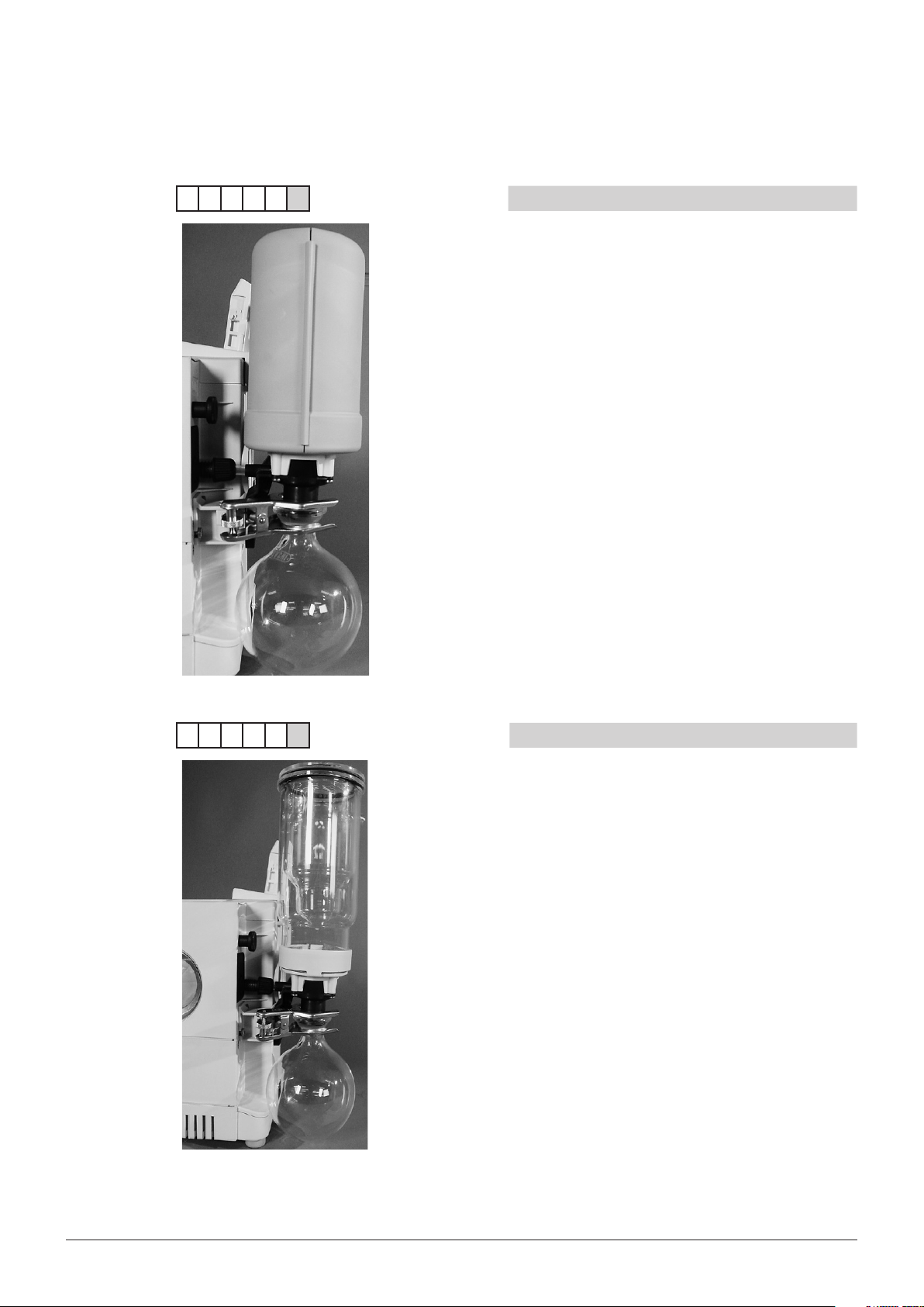
5.5 Woulff bottle or valve unit
To install the Woulff bottle, proceed as follows:
• Screw the corresponding holder to the pump.
NOTE
You can use the allen key integrated in the top cover of the
pump, see also Fig. 4.2.
30 V-700/710 Operation Manual, Version E
Page 31

• Introduce the Woulff bottle to the holder.
• Screw the GL-14 nut of the Woulff bottle to the GL-14 thread
of the pump inlet. It may be necessary to pull the tube a little
until it fits.
NOTE
If no vacuum controller is connected, close the connections at
the Woulff bottle, which are not in use, with screw caps.
Fig. 5.5: Installing the Woulff bottle
5.6 Vacuum connection to the vacuum controller
5 Putting into operation
a Vacuum connection to vacuum controller
b Vacuum connection to Rotavapor or other
instrument
1
1
2
Fig. 5.6: Vacuum connection to the vacuum controller
31 V-700/710 Operation Manual, Version E
Page 32

5 Putting into operation
5.7 Complete system connection with one Rotavapor and one vacuum controller
6
7
OUT
IN
8
9
1
4
5
1
1
O IN
H
2
2
3
4
O OUT
H
2
a Cooling water connections
b Communication cable vacuum pump / Rotavapor
c Communication cable vacuum controller / cooling
water valve
d Vacuum connection vacuum pump / Woulff bottle /
glass assembly
e PTFE tube for feeding the evaporating flask
Fig. 5.7: Complete system connection
f Communication cable vacuum controller / Auto-distilla-
tion probe
g Vacuum connection vacuum controller / Woulff bottle
h Communication cable vacuum controller / Rotavapor
i Communication cable Rotavapor (R-215) / vapor tem-
perature sensor
Liquid connections: a
Communication cable connections: b, c, e, f, h, i, j
Vacuum connections: d, g
NOTE
The power supply for the controller is assured via the Rotavapor and the pump.
For a detail view of the connections at the valve unit see also Fig. 4.12.
32 V-700/710 Operation Manual, Version E
Page 33

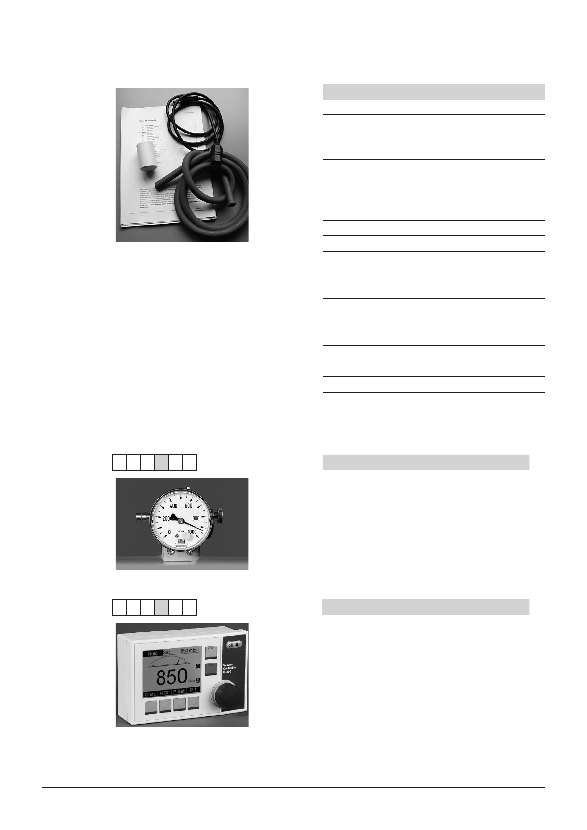
5.8 System pump with two controllers on two Rotavapor
5 Putting into operation
Fig. 5.8: Complete system connection with two Rotavapors
Legend:
1: Valve unit
Connections:
Thick line: Vacuum connections
Dotted line: Electrical connection vacuum controller (AS/SB) / vacuum controller (AS/SB) vacuum
pump (switch box) with cable 38010
Thin line: Electrical connection valve unit / vacuum controller (VALVE)
33 V-700/710 Operation Manual, Version E
Page 34

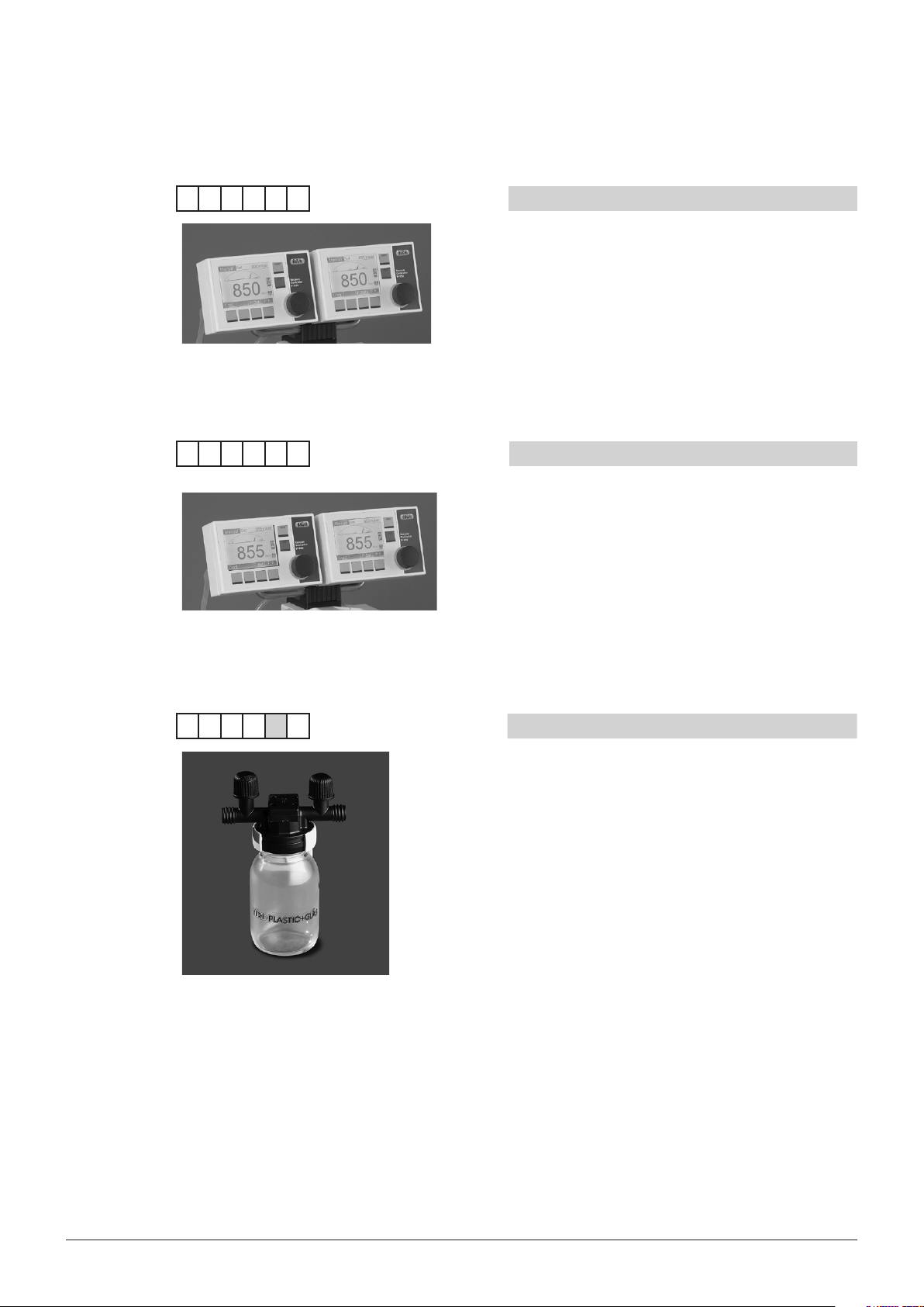
5.9 System pump with two controllers on one pump
Option 1
Option 1 is a variant with both controllers accessible from one side. This configuration offers
vacuum connections on the left and right hand
of the pump, connected to the appropriate
controller.
Both controllers can be operated from the front.
5 Putting into operation
Option 2
Option 2 is a variant with the controllers beeing
positioned in the opposite of each other. This
configuration is designed to be placed i.e. in the
middle of a working table, allowing access from
two different sides. The vacuum load is placed
aside of each controller, providing best accessibility.
The controllers can be operated from two sides.
34 V-700/710 Operation Manual, Version E
Page 35

5 Putting into operation
The following installation instruction is valid for both variants, although the controller holders of the
V-700 and the V-710 model are different in design. The update kit contains all necessary hoses in a
universal set.
• Remove the original valve holder from the pump
housing (two allen screws).
• Take the metal base plate (1) from the installation
kit and make sure its fold (3) is located downwards, with the edge towards you.
• Mount the valve holder (2) with two allen screws
from the kit to the rights side of the base plate.
• The round shape of the holder is to be placed
downwards, towards the fold of the base plate.
• Finally, use the original valve holder to fix the new
assembly at the pump housing (4).
Use the four screws (2) to fix the pump holder onto the controller holder (1). With the long center screw (3) the
whole adapter can be fixed at the pump.
35 V-700/710 Operation Manual, Version E
Page 36

Commissioning option 1 (parallel)
5 Putting into operation
To install the controllers proceed as follows:
• 1. Assemble the corresponding controller holder
as previously illustrated.
• 2. Mount the controller bracket on top of the
pump with the long center screw number (3).
• 3. To mount the metal lever in the designated
angle, turn it until the preinstalled clamb-screw
matches the small hole of the lever. Now, fixate
the lever with the clamb-screw.
• Mount both controllers at the controller bracket.
• Visually align the controllers in parallel at the
metal lever to avoid bending stress of the hoses
and sealings. This will enhance the durability of
the sealing.
• Use the two shorter hoses to connect the valve
unit to the controllers.
• Mount the shortest hose between the valve units
as illustrated in the picture to the left. Check all
sealings for proper function!
Retighten all connections at the pump. Again,
make sure the system is without leakages!
Note
• Itispossibletocombinedifferentcon-
troller types.
• EasyVacandLabVacarenopossible
options for this system.
36 V-700/710 Operation Manual, Version E
Page 37

Commissioning option 2 (opposite)
5 Putting into operation
To install the controllers proceed as follows:
• 1. Assemble the corresponding controller holder
as previously illustrated.
• 2. Mount the controller bracket on top of the
pump with the long center screw number (3).
• 3. To mount the metal lever in the designated
angle, turn it until the preinstalled clamb-screw
matches the small hole of the lever. Now, fixate
the lever with the clamb-screw.
• Mount both controllers at the controller bracket.
• Visually align the controllers in parallel at the
metal lever to avoid bending stress of the hoses
and sealings. This will enhance the durability of
the sealing.
• Use the two shorter hoses to connect the valve
unit to the controllers.
• Mount the shortest hose between the valve units
as illustrated in the picture to the left. Check all
sealings for proper function!
Retighten all connections at the pump. Again,
make sure the system is without leakages!
Note
• Itispossibletocombinedifferentcon-
troller types.
• EasyVacandLabVacarenopossible
options for this system.
37 V-700/710 Operation Manual, Version E
Page 38

Cabling
5 Putting into operation
How to connect the cables:
1. Use the two green power supply cables to
connect the pump to the controllers (shown
with dashed lines)
2. Use the grey-Y-cable to connect the pump to
the controllers’ AS/SB-connector. (shown as
solid line)
3. Link each calve unit to the VALVE connector of
the respective controller (shown with dotted
line).
Electrical connections
RJ45 : Power supply (dashed line)
Valve : Valve unit (dotted line)
CW : Control cable (solid line)
!
WARNING
Death or serious burnings by electric shock.
• Mains voltage must match the voltage reading on the type plate.
• Instrument must be earthed by the mains socket.
• Only use a molded 3-pole device plug (IEC-60320, type C13 or C15).
• Do not use damaged cables.
38 V-700/710 Operation Manual, Version E
Page 39

6 Operation
This chapter explains the operating elements and possible operating modes. It gives instructions on
how to operate the instrument properly and safely.
ATTENTION
Check the glassware for damages prior to each operation and use only glassware in perfect condition. Glassware with cracks, stars or other damages can break during operation.
6.1 Starting the pump
6.1.1 Pump without controller
After the pump is completely installed it is ready to operate, i.e. when the mains switch is pressed, the
pump starts operating right away and starts evacuating until the end vacuum (10 mbar with the V-700
and 2 mbar with the V-710). When the pump is operated continuously over a longer period of time it
automatically switches to the ECO² Mode (see chapter 4.5). In case the Vacuum Pump V-700 or V710 is part of a central lab source pump we recommend to use the Vacuum Module V-802 LabVac to
ensure an unreduced suction power during the whole operation time (see chapter 4.4).
6 Operation
6.1.2 Pump with controller
After the pump and the controller are completely installed, the system is ready to operate. When the
mains switch is pressed, the pump is on standby and starts operating as soon as the controller is
started. It then evacuates to the vacuum preset at the controller.
6.1.3 EasyVac
For a description of the EasyVac function, see chapter 4.3.
6.1.4 LabVac
For a description of the LabVac function, see chapter 4.4.
6.1.5 ECO2 Mode
For a description of the ECO2 Mode, see chapter 4.5.
39 V-700/710 Operation Manual, Version E
Page 40

6.2 Selecting the distillation conditions
To achieve optimal distillation conditions, the distillation energy supplied by the heating bath must be
removed by the condenser.
To ensure this, operate the instrument according to the following rule of thumb:
Cooling water: max. 20 °C Vapor: 40 °C Bath: 60 °C
How are these conditions achieved?:
• Set the bath temperature to 60 °C.
• Set the cooling water temperature not higher than 20 °C.
• Allow cooling water to flow through the condenser: >1.2 l/min (continuous not pulsed).
• Define the operating vacuum in such a way, that the boiling point of the solvent is 40 °C. The corre-
sponding pressure can be seen from the Solvent Table in chapter 3.
Advantages associated with bath temperatures of 60 °C:
• The evaporating flask can be replaced without risk of burns.
• The evaporation rate of the water from the heating bath is low (low energy loss).
• The heating bath energy is used at a good degree of efficiency.
This rule can also be applied to lower bath temperatures, e.g.:
Cooling water: 0 °C Vapor: 20 °C Bath: 40 °C
6 Operation
Δ T2 (min. 20 °C)
Fig. 6.1: 20-40-60 ° rule
Δ T1 (min. 20 °C)
40 V-700/710 Operation Manual, Version E
Page 41

6.3 Optimizing the distillation conditions
Depending on the solvent being distilled the distillation might have to be re-optimized. In the optimized
case, the condenser should be steamed up to between 2/3 to 3/4, see figure below.
If this is not the case, there are two possibilities to optimize the distillation:
• When the heating bath has reached 60 °C slowly reduce the pressure. Thus, the boiling point of
the solvent is reduced and Δ T
• When the heating bath has reached 60 °C increase the bath temperature. Thus Δ T
resulting in an increase of distillation capacity as well.
NOTE
When the bath temperature is increased, not all of the additional energy is used for distillation but a
major part is discharged into the environment due to the increasing difference between heating bath
and the ambient temperature.
increases resulting in an increase of distillation capacity.
1
6 Operation
increases
1
3/4
Fig. 6.2: Optional condensation area of a condenser
41 V-700/710 Operation Manual, Version E
Page 42

7 Maintenance and repairs
This chapter gives instructions on all maintenance work to be performed in order to keep the instrument in good working condition. In addition to this, adjustment jobs the operator can carry out by
himself/herself are explained.
WARNING
All maintenance and repair work requiring the opening or removal of instrument covers may only be
carried out by trained personnel and with the tools provided for this purpose.
WARNING
Electrical hazard:
• Prior to all maintenance work on the instrument switch off the power supply and remove all
sources of flammable vapor.
ATTENTION
Use only genuine consumables and genuine spare parts for maintenance and repair to assure good
system performance and reliability. Any modifications to the spare parts used are only allowed with
the prior written permission of the manufacturer.
7 Maintenance and repairs
7.1 Housing
Immediate maintenance
The housing is made of plastic. Remove any acid drops immediately from the housing with a moist
cloth.
General maintenance
Check the housing for defects (controls, plugs) and clean it regularly with a moist cloth.
ATTENTION
Never use organic solutions (except for ethanol) as cleaning agents as these might damage the
instrument.
7.2 Glass parts
Rinse the glass parts regularly with standard cleaning agents (e.g. mild soap solutions).
Afterwards examine them visually for splintered parts or cracks.
ATTENTION
Check the glassware for damages prior to each operation and use only glassware that is in perfect
condition. Glassware with cracks, stars or other damages can break during operation.
7.3 Hoses and gaskets
Examine hoses and gaskets visually for cracks. If cracks have developed or if the tubes and gaskets
have become brittle, replace them with suitable new ones.
42 V-700/710 Operation Manual, Version E
Page 43

7.4 Valve head
7.4.1 Cleaning
If the end vacuum of 10 mbar is not reached anymore and the rest of the system has no leakage, the
problem is often caused by stuck valve plates.
To clean them, proceed as follows:
• Remove all connections to the pump and to the silencer.
• Switch the pump on.
• Inject a small amount of about approx. 10 ml of acetone at once into the inlet side of the pump and
wait until the pump makes the same sound as before injecting solvent.
NOTE
Use safety washing bottles to inject the acetone, as shown in Fig. 7.1.
• Repeat the injection step four to five times.
• Let the pump run for about 2 minutes and check whether the end vacuum can be reached.
• If this is still not the case, repeat the cleaning procedure before going on with any disassembly
work.
7 Maintenance and repairs
Fig. 7.1: Cleaning the valve head with acetone
7.4.2 Disassembly and reassembly of the pump head
To disassemble the pump to replace the membrane and valves, proceed as follows:
43 V-700/710 Operation Manual, Version E
• Remove the two knurled screws for fixing the
upper part (position 4 in Fig. 4.2) and pull the
housing off.
NOTE
To replace only the valves you do not have to
remove the metal cover and the pump head.
Page 44

7 Maintenance and repairs
• Remove the two rubber parts at the valve in-
and outlet.
• Loosen the black tube clips GL-14 between
the pump heads.
• Turn the pump on its side.
• By means of the allen key in the pump
housing (for the position of the key, see Fig.
4.2) loosen the four screws at the glass/PEEK
head.
• Remove the metal cover and the pump head.
• Use the membrane key to loosen the
membrane by unscrewing it counterclockwise.
NOTE
Handle the diaphragm with care and make sure
it is not damaged when removing and mounting
it.
44 V-700/710 Operation Manual, Version E
Page 45

7 Maintenance and repairs
• In case the valve has to be replaced, loosen
1
1
the two screws a by means of the allen key
in the pump housing.
• Replace the valve (the picture on the left
shows the replacement of the valve on the
OUT side).
Pump inlet Pump outlet
Check-valves V-700
Pump inlet
Pump outlet
A description of how to mount the valve can be
seen from the pump housing (the IN side is illustrated at the top of the picture on the left, the
OUT side is illustrated at the top of the picture
on the right). The upper image shows the installation on a V-700. The lower image shows the
installation on a V-710.
NOTE
Consider the mounting direction of the valve as
this is vital for the functioning of the pump. To
check whether the mounting is correct, blow
into the tube at the IN side. You should then feel
the air coming out of the OUT side.
Check-valves V-710
45 V-700/710 Operation Manual, Version E
Page 46

Fig. 7.2: Disassembling and reassembling the valve heads
7.5 Working with strong acids
7 Maintenance and repairs
• When all replacement work is done, reas-
semble the pump head in the reverse order.
NOTE
When remounting the valve head, fix the four
screws slightly at first, and then tighten them
crosswise (recommended torque 5.5 Nm).
ATTENTION
Always wear personal protective equipment such as protective eye goggles, protective clothing and
gloves when operating the instruments with strong acids or bases.
In case you distill strong acids or bases, we recommend highly that you rinse the pump after the distillation process to increase the lifetime of the instrument.
To rinse the pump, proceed as follows:
• Suck 5–10 ml of water through the pump inlet and recollect it again directly behind the pump
outlet.
• Check the pH value of the water leaving the pump and repeat the rinsing procedure until the value
is between a pH of 3–9.
• Now dry the pump by sucking air through it for 2–3 minutes.
7.6 Customer service
Only authorised service personnel are allowed to perform repair work on the instrument. These
persons have a comprehensive technical training and knowledge of possible dangers which might
arise from the instrument.
Addresses of official BUCHI customer service offices are given on the BUCHI website under:
www.buchi.com. If malfunctions occur on your instrument or you have technical questions or application problems, contact one of these offices.
The customer service offers the following:
• Spare part delivery
• Repairs
• Technical advice
46 V-700/710 Operation Manual, Version E
Page 47

8 Troubleshooting
This chapter helps to resume operation after a minor problem has occurred with the instrument. It lists
possible occurrences, their probable cause and suggests how to remedy the problem.
The troubleshooting table below lists possible malfunctions and errors of the instrument. The operator
is enabled to correct some of those problems or errors by him/herself. For this, appropriate corrective
measures are listed in the column “Corrective measure”.
The elimination of more complicated malfunctions or errors is usually performed by a BUCHI technical
engineer who has access to the official service manuals. In this case, please refer to your local BUCHI
customer service agent.
8.1 Malfunctions and their remedy
Table 8-1: General malfunction and their remedy
Malfunction Possible cause Corrective measure
Instrument does not work Mains switch off Switch on mains switch
System is leaky or does not reach
the end vacuum
Contact at the removable top cover is
not closed
8 Troubleshooting
Instrument is not connected to power
supply
Instrument is not connected to power
supply
Tube clips have not been fixed
correctly or are defective
Tubes are leaky (brittle) Replace tubes
Membrane and/or valves are
contaminated
Top cover not perfectly mounted Check the mounting of the top cover
Check if mains connection is okay
Check mains connection
Check tube clips
Clean or replace membrane and/or
valves
and refix it, if necessary
47 V-700/710 Operation Manual, Version E
Page 48

9 Shutdown, storage, transport and disposal
9 Shutdown, storage, transport and disposal
This chapter instructs how to shut down the instrument, how to pack it for storage or transport, and
specifies the storage and shipping conditions.
9.1 Storage and transport
WARNING
Biohazard:
• Remove all dangerous substances from the instrument and clean it thoroughly.
Store and transport the instrument in its original packaging.
WARNING
Electrical hazard:
• Always remove the plug connector at the socket first to avoid having energized cables lying about.
9.2 Disposal
To dispose of the instrument in an environmentally friendly manner, a list of materials is given in
chapter 3. This helps to ensure that the components are separated and recycled correctly. Make
especially sure to dispose of the gas springs appropriately.
Please follow valid regional and local laws concerning disposal.
NOTE
When you send the instrument back to the manufacturer for repair work, please copy the health and
safety clearance form on the following page, fill it in and enclose it in the instrument package.
48 V-700/710 Operation Manual, Version E
Page 49

9.3 Health and safety clearance form
Declaration concerning safety, potential hazards and safe disposal of waste, e.g. used oil.
Safety and health of our staff, laws and regulations regarding the handling of dangerous goods, occupational health and safety
regulations, safety at work laws and regulations regarding safe disposal of waste, e.g. waste oil, require that for all pumps and
other products this form must be send to our office duly completed and signed before any equipment is repaired or dispatched
to our premises.
Products will not be accepted for any procedure and handling and repair / DKD calibration will not start before we
have received this declaration.
a) Fax or post a completed copy of this form to us in advance. The declaration must arrive before the equipment. Enclose
a second, completed copy with the product. If the product is contaminated you must notify the carrier (GGVE, GGVS,
RID, ADR).
b) Inevitably, the repair process will be delayed considerably, if this information is missing or this procedure is not obeyed. We
hope for your understanding for these measures which are beyond our control and that you will assist us in expediting the
repair procedure.
c) Make sure that you know all about the substances which have been in contact with the equipment and that all
questions have been answered correctly and in detail.
9 Shutdown, storage, transport and disposal
1. Product (Model): ..........................................
2. Serial No.: .....................................................
3. List of substances in contact with the
equipment or reaction products:
3.1 Chemical/substance name, chemical
symbol:
a) .........................................................................
b) .........................................................................
c) .........................................................................
d) .........................................................................
3.2 Important information and precautions,
e.g. danger classification
a) .........................................................................
b) .........................................................................
c) .........................................................................
d) .........................................................................
4. Declaration (please mark as applicable):
¤ 4.1 for non dangerous goods:
We assure for the returned product that
- neither toxic, corrosive, bilogically active, explosive, radioac-
tive nor contamination dangerous in any way has occurred.
- the product is free of dangerous substances.
The oil or residues of pumped media have been drained.
5. Way of transport / carrier:
.............................................................................
Day of dispatch to BÜCHI Labortechnik AG:
.............................................................................
We declare that the following measures where applicable - have been taken:
- The oil has been drained from the product.
Important: Dispose of according to national
regulations.
- The interior of the product has been cleaned.
- All inlet and outlet ports of the product have been sealed.
- The product has been properly packed, if necessary, please
order an original packaging (costs will be charged) and
marked as appropriate.
- The carrier has been informed about the hazardous nature of
goods (if applicable).
Signature: ...............................................................................
Name (print): ...........................................................................
Job title (print): ........................................................................
Company’s seal: .....................................................................
Date: .......................................................................................
¤ 4.2 for dangerous goods:
We assure for the returned product that
- all substances, toxic, corrosive, biologically active, explosive,
radioactive or dangerous in any way which have pumped or
been in contact with the product are listed in 3.1, that the
information is complete and that we have not withheld any
information.
- the product, in accordance with regulations, has been
¤ cleaned
¤ decontaminated
¤ sterilized
49 V-700/710 Operation Manual, Version E
Page 50

10 Spare parts and accessories
This chapter lists spare parts, accessories, and options including their ordering information.
Order the spare parts from BUCHI. Always state the product designation and the part number when
ordering spare parts.
Use only genuine BUCHI consumables and genuine spare parts for maintenance and repair to assure
good system performance and reliability. Any modifications to the spare parts used are only allowed
with the prior written permission of the manufacturer.
10.1 Spare parts
1
4
10 Spare parts
Table 10-1: Spare parts
Product Order number
Secondary condenser complete,
with receiving flask, 500 ml
a Secondary condenser 47181
47180
2
3
b Clip 03275
c Receiving flask, 500 ml 00424
d Insulating secondary condenser 47183
O-ring for secondary condenser 11057661
Secondary cold trap complete,
with receiving flask, P+G coated
Secondary cold trap, P+G coated 47191
Receiving flask, 500 ml, P+G coated 40774
Vacuum Controller V-850 for R-210/215
and V-700/710
Vacuum Controller V-855 for R-210/215
and V-700/710
Vacuum Module V-801 EasyVac 47252
47190
47299
47298
Vacuum Module V-802 LabVac 47254
Manometer with needle valve complete (for
manual vacuum control) including support
for R-210/215, V-700/710 and V-850/855
50 V-700/710 Operation Manual, Version E
47291
Page 51

10 Spare parts
Table 10-1: Spare parts (cont.)
Product Order number
Control cable between vacuum controller
and Vacuum Pump RJ 45,
330 mm (speed control)
Control cable for Vacuum Controller V-500/
V-1000, compatible with Vacuum Controller
V-800/805
Control cable between Rotavapor and
Vacuum Pump RJ 45,
2000 mm (speed control)
5000 mm (speed control)
Support set for vacuum controller /
manometer with needle valve for
R-210/215, V-700/710
Cooling water valve 24 V for Vacuum
Controller V-800/805 and V-850/855
44288
38010
44989
11056240
47280
31356
Vacuum tube Ø 16/6 mm a 17622
1
2
4
3
Cooling water tube silicone Ø 9/6 mm b 04133
FEP hose, Ø 8.0 x 1.0 c 27900
Nyflex tube Ø 14 x 8 d 04113
Membrane complete including tongs 47153
Set of 10 membranes 11055214
FEP-tube 47066
Upgrade kit V-700 to V-704 047419
Upgrade kit V-710 to V-714 047422
51 V-700/710 Operation Manual, Version E
Page 52

10 Spare parts
Table 10-1: Spare parts (cont.)
Product Order number
47152
47150
Woulff bottle complete (with R-210/215 and
47170
V-700/710) for Vacuum Controller
V-800/805 and V-850/855
Woulff bottle glas part, P+G coated 47233
Holder for woulff bottle and valve unit 47164
Valve unit 47160
Pump head, 1 piece 47015
Outlet pump head complete, consisting of 1
47009
pump head, outlet connector complete and
angled connector complete
Inlet pump head complete, consisting of 1
47010
pump head, inlet connector complete and
angled connector complete
47151
47152
Outlet connector complete, including valve 47150
Inlet connector complete, including valve
47151
and gas ballast
Angled connector complete, including valve 47152
Piping parallel V-710 (Valves and O-rings
47306
included)
Piping serial V-710 ( Valve and O-rings
47307
included)
Hose kit V-710 11055496
52 V-700/710 Operation Manual, Version E
Page 53

10 Spare parts
Table 10-1: Spare parts (cont.)
Product Order number
Set of 4 valves, including O-rings and
47156
screws
Set of 4 valves (without O-rings and
11058389
screws)
Set of 8 check-valves and 11 O-rings and
11057438
screws for V-710
Set of 4 O-rings (FFKM) 11057136
Silencer 47090
Knurled nut to fix the pump housing 46683
53 V-700/710 Operation Manual, Version E
Page 54

11 Declarations and requirements
11.1 FCC requirements (for USA and Canada)
English:
This equipment has been tested and found to comply with the limits for a Class A digital device,
pursuant to both Part 15 of the FCC Rules and the radio interference regulations of the Canadian
Department of Communications. These limits are designed to provide reasonable protection against
harmful interference when the equipment is operated in a commercial environment.
This equipment generates, uses and can radiate radio frequency energy and, if not installed and used
in accordance with the instruction manual, may cause harmful interference to radio communications.
Operation of this equipment in a residential area is likely to cause harmful interference in which case
the user will be required to correct the interference at his own expense.
Français:
Cet appareil a été testé et s'est avéré conforme aux limites prévues pour les appareils numériques
de classe A et à la partie 15 des réglementations FCC ainsi qu’à la réglementation des interférences
radio du Canadian Department of Communications. Ces limites sont destinées à fournir une protection adéquate contre les interférences néfastes lorsque l’appareil est utilisé dans un environnement
commercial.
Cet appareil génère, utilise et peut irradier une énergie à fréquence radioélectrique, il est en outre
susceptible d’engendrer des interférences avec les communications radio, s’il n’est pas installé et
utilisé conformément aux instructions du mode d’emploi. L’utilisation de cet appareil dans les zones
résidentielles peut causer des interférences néfastes, auquel cas l’exploitant sera amené à prendre les
dispositions utiles pour palier aux interférences à ses propres frais.
11 Declarations and requirements
54 V-700/710 Operation Manual, Version E
Page 55

11.2 Declaration of conformity
11 Declarations and requirements
55 V-700/710 Operation Manual, Version E
Page 56

Page 57

Page 58

BÜCHI Labortechnik AG
CH-9230 Fl awil 1 / Switze rland
T +41 71 394 63 63
F +41 71 394 65 65
www.buchi.com Quality in your hands
 Loading...