

Page 1

SpeedExtractor E-916 / E-914
Operation Manual
093218F en
Page 2

Imprint
Product Identification:
Operation Manual (Original), SpeedExtractor E-916 / E-914
093218F en
Publication date: 05.2019
BÜCHI Labortechnik AG
Meierseggstrasse 40
Postfach
CH-9230 Flawil 1
E-Mail: quality@buchi.com
BUCHI reserves the right to make changes to the manual as deemed necessary in the light of experience; especially in respect to structure, illustrations and technical detail.
This manual is copyright. Information from it may not be reproduced, distributed, or used for competitive purposes, nor made available to third parties. The manufacture of any component with the aid of this manual without
prior written agreement is also prohibited.
Page 3

Table of contents
Table of contents
1 About this manual .............................................................................................................................................................. 5
1.1 Reference documents ......................................................................................................................................... 5
1.2 Trademarks .............................................................................................................................................................. 5
1.3 Abbreviations ......................................................................................................................................................... 6
2 Safety ...................................................................................................................................................................................... 7
2.1 User qualication .................................................................................................................................................. 7
2.2 Proper use ................................................................................................................................................................ 7
2.3 Improper use .......................................................................................................................................................... 7
2.4 Safety warnings and safety signs used in this manual ............................................................................ 8
2.5 Product safety ......................................................................................................................................................10
2.5.1 General hazards .....................................................................................................................................10
2.5.2 Warning labels on housing and assemblies ................................................................................11
2.5.3 Personal protective equipment .......................................................................................................11
2.5.4 Built-in safety elements and measures .........................................................................................12
2.6 General safety rules ............................................................................................................................................13
3 Technical data .................................................................................................................................................................... 15
3.1 Scope of delivery .................................................................................................................................................15
3.2 Instrument congurations ...............................................................................................................................15
3.3 Materials used ......................................................................................................................................................18
3.4 Technical data overview ...................................................................................................................................18
4 Description of function .................................................................................................................................................. 21
4.1 Functional principle ...........................................................................................................................................21
4.2 Overview of the instrument ............................................................................................................................ 21
4.3 Overview of the extraction process ............................................................................................................. 23
4.4 Schematic representation of the process ..................................................................................................24
4.5 Controls and connections ................................................................................................................................25
4.5.1 Instrument controls ..............................................................................................................................25
4.5.2 Main displays of the instrument ......................................................................................................26
4.5.3 General information on buttons ......................................................................................................29
4.5.4 Rear connections ................................................................................................................................... 30
4.5.5 Side connections ................................................................................................................................... 30
5 Putting into operation .................................................................................................................................................... 31
5.1 Installation site .....................................................................................................................................................31
5.2 Electrical connections ....................................................................................................................................... 32
5.3 Gas and solvent connections..........................................................................................................................33
5.4 Dehydration ..........................................................................................................................................................34
5.5 Functional test .....................................................................................................................................................34
2 SpeedExtractor E-916 / E-914 Operation Manual
Page 4

Table of contents
6 Operation ............................................................................................................................................................................35
6.1 Method development .......................................................................................................................................35
6.2 Preparing the instrument ................................................................................................................................36
6.2.1 Solvent reservoir ....................................................................................................................................36
6.2.2 Modifying the SOLVENT LIST ............................................................................................................37
6.2.3 Preheating the instrument ................................................................................................................38
6.2.4 Activating/deactivating positions ...................................................................................................39
6.2.5 Leak test ....................................................................................................................................................40
6.2.6 Flushing the instrument .....................................................................................................................43
6.2.7 Activating the EcoMode .....................................................................................................................44
6.3 Preparing the sample ........................................................................................................................................45
6.3.1 Sample preparation ..............................................................................................................................45
6.3.2 Extraction cell selection ...................................................................................................................... 46
6.3.3 Packing of the cells ...............................................................................................................................46
6.4 Extraction process ..............................................................................................................................................49
6.4.1 Placing the cells and bottles/vials into the instrument ...........................................................49
6.4.2 Stages of an extraction cycle ............................................................................................................ 50
6.4.3 Creating new methods ........................................................................................................................51
6.4.4 Summary of operating parameters ................................................................................................54
6.4.5 Example of an extraction method ..................................................................................................56
6.4.6 Open an existing method ..................................................................................................................56
6.4.7 Optimize a process ...............................................................................................................................57
6.4.8 Start, pause, stop and abort extraction .........................................................................................58
6.4.9 Post-extraction procedures ...............................................................................................................58
6.5 Creating a report (optional) ............................................................................................................................59
7 Maintenance ....................................................................................................................................................................... 61
7.1 Daily maintenance ..............................................................................................................................................61
7.2 Periodic maintenance .......................................................................................................................................62
7.2.1 Sealing system........................................................................................................................................62
7.2.2 Replacing the cup seals ......................................................................................................................62
7.2.3 Tube connections and needles ........................................................................................................63
7.2.4 Septum ...................................................................................................................................................... 65
7.3 Pump maintenance ............................................................................................................................................66
7.3.1 Connections ............................................................................................................................................66
7.3.2 Back washing ..........................................................................................................................................67
8 Troubleshooting................................................................................................................................................................69
8.1 Malfunctions and their remedy ..................................................................................................................... 69
8.1.1 Action in case of a re ..........................................................................................................................69
8.1.2 General malfunctions and their remedy .......................................................................................69
8.1.3 Handling and resolving blockages ................................................................................................. 74
8.1.4 The pump is not aspirating properly .............................................................................................79
8.1.5 Replacement of check valves ............................................................................................................80
8.1.6 Precipitation in the outlet lines ........................................................................................................81
8.1.7 Malfunctions of the rotating valves ................................................................................................82
8.1.8 Upgrading a 2-port mixer to a 4-port mixer ................................................................................82
3 SpeedExtractor E-916 / E-914 Operation Manual
Page 5

Table of contents
8.2 Description of the service menu ................................................................................................................... 83
8.2.1 Checking the valves .............................................................................................................................84
8.2.2 Checking the sensors ........................................................................................................................... 85
8.2.3 Running the pump ...............................................................................................................................85
8.2.4 Inspecting the lines (ow test) ......................................................................................................... 86
8.2.5 Moving the cell and vial lift ...............................................................................................................88
8.2.6 Changing the fan performance........................................................................................................88
8.2.7 Displaying the operating hours .......................................................................................................88
8.2.8 Unit information ....................................................................................................................................88
8.3 Customer service.................................................................................................................................................89
9 Shutdown, storage, transport and disposal ............................................................................................................91
9.1 Storage and transport ....................................................................................................................................... 91
9.2 Disposal ..................................................................................................................................................................92
9.3 Health and safety clearance ............................................................................................................................93
10 Spare parts .......................................................................................................................................................................... 95
11 Declarations and requirements .................................................................................................................................105
11.1 FCC requirements (for USA and Canada) ................................................................................................105
Read this manual carefully before installing and running your system and note the safety precautions in chapter 2
in particular. Store the manual in the immediate vicinity of the instrument, so that it can be consulted at any time.
No technical modications may be made to the instrument without the prior written agreement of BUCHI. Unauthorized modications may aect the system safety or result in accidents.
This manual is copyright. Information from it may not be reproduced, distributed, or used for competitive purposes, nor made available to third parties. The manufacture of any component with the aid of this manual without
prior written agreement is also prohibited.
The English manual is the original language version and serves as basis for all translations into other
languages. If you need another language version of this manual, you can download available versions
at www.buchi.com.
4 SpeedExtractor E-916 / E-914 Operation Manual
Page 6

1 About this manual
This manual describes the SpeedExtractor E-916 / E-914 and provides all information required for
its safe operation and to maintain it in good working order. It is addressed in particular to laboratory
personnel and operators.
NOTE
The symbols pertaining to safety are explained in chapter2.
1.1 Reference documents
For information on complementary BUCHI devices, please refer to the corresponding manuals:
Complementary devices
Multivapor P-6 / P-12, Operation Manual
Vacuum Controller, Operation Manual
Vacuum Pump, Operation Manual
Syncore Platform, Operation Manual
Syncore Accessories, Operation Manual
1 About this manual
NOTE
• All manuals are available via www.buchi.com
• For download a free online registration is required
1.2 Trademarks
The following product names and any registered and unregistered trademarks mentioned in this
manual are used for identication purposes only and remain the exclusive property of their respective
owners:
• SpeedExtractor is a registered trademark of BÜCHI Labortechnik AG
• ASE is a registered trademark of Dionex Corporation
5 SpeedExtractor E-916 / E-914 Operation Manual
Page 7

1.3 Abbreviations
Process-related
ASE Accelerated Solvent Extraction
PSE Pressurized Solvent Extraction
Materials and chemicals
FEP Combination of tetrauoroethylene and hexauoropropylene
FFPM Peruoro caoutchouc
PTFE Polytetrauoroethylene
POM Polyoxymethylene (commercialized as Delrin® by DuPont)
PEEK Polyether ether ketone
THF Tetrahydrofurane
Miscellaneous
FW rm ware
qty quantity
DT Temperature dierence
Dp Pressure dierence
1 About this manual
6 SpeedExtractor E-916 / E-914 Operation Manual
Page 8

2 Safety
This chapter highlights the safety concept of the SpeedExtractor and contains general rules of behavior and warnings about hazards concerning the use of the product.
The safety of users and personnel can only be ensured if these safety instructions and the safety related warnings in the individual chapters are strictly observed and followed, therefore, the manual must
always be available to all persons performing the tasks described herein.
2.1 User qualication
The instrument may be used only by laboratory personnel or other persons who on account of instruction or professional experience have an overview of the dangers that can develop when operating the
instrument.
Personnel without such instruction or persons who are currently being trained require careful supervision.
The present Operation Manual serves as a basis for instruction.
2 Safety
2.2 Proper use
The instrument has been designed and built for laboratory use only. It serves for activities associated
with the parallel extraction of multiple samples by means of heating under pressure. The pressure is
typically applied by the HPLC pump.
2.3 Improper use
Applications beyond those described above are improper. Furthermore, applications that do not
comply with the technical data are also considered improper. The operator bears the sole risk for any
damage caused by such improper use.
The following applications are expressly forbidden:
• Use of solvents with an self ignition point between 40 to 220°C.
• Use of the instrument in rooms that require ex-protected instruments.
• Use as a calibrating instrument for other instruments.
• Preparation of samples that can explode or iname due to shock, friction, heat, or spark formation.
• Use in high pressure situations, i.e. > 200bar.
• Use in conjunction with solvents that have a low self ignition point or contain peroxides, such as
diethyl ether or THF.
• Use of cells, seals, hoses, and tubes other than the originals from BUCHI.
7 SpeedExtractor E-916 / E-914 Operation Manual
Page 9

2.4 Safety warnings and safety signs used in this manual
DANGER, WARNING, CAUTION and NOTICE are standardized signal words for identifying levels of
hazard seriousness of risks related to personal injury and property damage. All signal words, which are
related to personal injury are accompanied by the general safety sign.
For your safety it is important to read and fully understand the table below with the dierent signal
words and their denitions!
Sign Signal word Definition Risk level
!
DANGER
Indicates a hazardous situation which, if not avoided, will result in
death or serious injury.
2 Safety
★★★★
WARNING
!
CAUTION
!
NOTICE
no
Supplementary safety information symbols may be placed in a rectangular panel on the left to the
signal word and the supplementary text (see below example).
Space for
supplementary
safety
information
symbols.
Table of supplementary safety information symbols
The reference list below incorporates all safety information symbols used in this manual and their
meaning.
Indicates a hazardous situation which, if not avoided, could result
in death or serious injury.
Indicates a hazardous situation which, if not avoided, may result
in minor or moderate injury.
Indicates possible property damage, but no
practices related to personal injury.
!
SIGNAL WORD
Supplementary text, describing the kind and level of hazard/risk seriousness.
• List of measures to avoid the herein described, hazard or hazardous situation.
• ...
• ...
★★★☆
★★☆☆
★☆☆☆
(property damage only)
Symbol Meaning
General warning
Electrical hazard
Harmful to life-forms
8 SpeedExtractor E-916 / E-914 Operation Manual
Page 10

Symbol Meaning
Fire hazard
Hot item, hot surface
Device damage
Inhalation of substances
2 Safety
Chemical burns by corrosives
Wear laboratory coat
Wear protective goggles
Wear protective gloves
Heavy weight, lifting requires more than one person
Additional user information
Paragraphs starting with Note transport helpful information for working with the device/software or its
supplementary. Notes are not related to any kind of hazard or damage.
NOTE
Useful tips for the easy operation of the instrument/software.
9 SpeedExtractor E-916 / E-914 Operation Manual
Page 11

2.5 Product safety
The SpeedExtractor has been designed and built in accordance with current state-of-the-art technology. Safety warnings in this manual (as described in section 2.4) serve to make the user alert to and
avoid hazardous situations emanating from residual dangers by giving appropriate counter measures.
However, risks to users, property and the environment can arise when the instrument is damaged,
used carelessly or improperly.
2.5.1 General hazards
The following safety messages show hazards of general kind which may occur when handling the
instrument. The user shall observe all listed counter measures in order to achieve and maintain the
lowest possible level of hazard.
Additional warning messages can be found whenever actions and situations described in this manual
are related to situational hazards.
2 Safety
!
WARNING
Death or serious injuries by formation of explosive atmospheres inside the instrument.
• Before operation, check all gas connections for correct installation
• Regularly discharge the waste bottle to avoid overow
• Check for proper system tightness
!
DANGER
Death or serious injuries by use in explosive environments.
• Do not store or operate the instrument in explosive environments
• Provide sucient ventilation and make sure to directly withdraw fumes
!
WARNING
Death or serious burns by ammable vapors.
• Remove all sources of ammable vapors
• Do not store ammable chemicals in the vicinity of the device
!
CAUTION
Risk of burns by hot heating block and extraction cells.
• Do not touch hot parts or surfaces
• Let the system and inserted extraction cells cool down safely
• Do not move the instrument or parts of it when hot
10 SpeedExtractor E-916 / E-914 Operation Manual
Page 12

2 Safety
Risk of instrument damage by liquids or mechanical shocks.
• Do not spill liquids over the instrument or its components
• Do not move the instrument when it is loaded with sample liquid
• Do not drop the instrument or its components
• Keep external vibrations away from the instrument
• Safely attach the instrument to the bench in earthquake prone regions
• Do not operate the instrument without the safety shield installed
Risk of instrument damage by wrong mains supply.
• External mains supply must meet the voltage given on the type plate
• Check for sucient grounding
2.5.2 Warning labels on housing and assemblies
The following warning sticker(s) can be found on the housing or assemblies of the SpeedExtractor:
Symbol Meaning Location
NOTICE
NOTICE
Hot item, hot surface Sticker/label, located at the heating block
2.5.3 Personal protective equipment
Always wear personal protective equipment such as protective eye goggles, protective clothing and
gloves. The personal protective equipment must meet all requirements of the supplementary data
sheets for the chemicals used.
!
Serious chemical burns by corrosives.
• Observe supplementary data sheets of all used chemicals.
• Handle corrosives in well ventilated environments only.
• Always wear protective goggles.
• Always wear protective gloves.
• Always wear protective clothes.
• Do not use damaged glassware.
WARNING
11 SpeedExtractor E-916 / E-914 Operation Manual
Page 13

2.5.4 Built-in safety elements and measures
• The heating element is equipped with overtemperature protection which is activated at
260°C±10°C.
• The pressure parts are protected by a mechanical pressure control valve which is activated at
200bar±20bar.
• To start a program at least one extraction position must be activated.
• Safety shield sensor: To start an extraction the protection shield must be closed.
• Vial rack sensor: To start an extraction the vial rack must be installed.
• The presence of extraction cells in the heating block is checked in the tightness test at the beginning of each extraction process.
2 Safety
Seismic tie-down
In earthquake-susceptible regions the instrument
should be tied down by the ventilation slot on the
rear of the instrument.
12 SpeedExtractor E-916 / E-914 Operation Manual
Page 14

2.6 General safety rules
Responsibility of the operator
The head of the laboratory is responsible for training his/her personnel.
The operator shall inform the manufacturer without delay of any safety-related incidents which might
occur during operation of the instrument or its accessories. Legal regulations, such as local, state and
federal laws applying to the instrument or its accessories must be strictly followed.
Duty of maintenance and care
The operator is responsible for the proper condition of instrument. This includes maintenance, service
and repair jobs that are performed on schedule by authorized personnel only.
Spare parts to be used
Use only genuine consumables and spare parts for maintenance to assure good system performance,
reliability and safety. Any modications of spare parts or assemblies are only allowed with the prior
written permission of the manufacturer.
Modications
Modications to the instrument are only permitted after prior consultation and with the written approval
of the manufacturer. Modications and upgrades shall only be carried out by an authorized BUCHI
technical engineer. The manufacturer will decline any claim resulting from unauthorized modications.
2 Safety
13 SpeedExtractor E-916 / E-914 Operation Manual
Page 15

2 Safety
14 SpeedExtractor E-916 / E-914 Operation Manual
Page 16

3 Technical data
This chapter introduces the reader to the SpeedExtractor and its main components. It contains technical data, requirements and performance data.
3.1 Scope of delivery
Check the scope of delivery according to the order number and your shipping note.
NOTE
For detailed information on the listed products, see www.buchi.com or contact your local dealer.
3.2 Instrument congurations
The SpeedExtractor is available in 18 dierent congurations diering in the number of positions (E-916:
6 positions, E-914: 4 positions), the type of solvent mixer (2 ports or 4 ports), and the size of the extraction
cells (E-916: 10 – 40mL, E-914: 10 – 120mL). The SpeedExtractor E-914 is available with and without pedestal (the pedestal allows to accommodate large volume collection recipients).
3 Technical data
E-914 without and with pedestal
15 SpeedExtractor E-916 / E-914 Operation Manual
Page 17

3 Technical data
1 1
5 1
c
Number of positions
4 E-914: 4 positions
5 E-914: 4 positions mounted on pedestal
6 E-916: 6 positions
Size of extraction cells
01 10mL (E-916 only)
02 20mL (E-916 only)
04 40mL
08 80mL (E-914 only)
12 120mL (E-914 only)
Number of solvent ports
2 Ports
4 Ports
d
e
f
i
p
j
q
b
k
r
s
m
l
t
053691 053690
a
h
g
n
o
List of loose parts
Position Item PU Universal Order no. E-914 Order no. E-916
a
b
c
d
e
f
g
h
i
FEP tube D3.2/1.6, 5m 2 110556 0 4
FEP waste tube 1/16", 0.5m 4/6 053303
Solvent bottle 1 L 1 053203
Quartz sand 0.3–0.9mm, 2.5kg 1 037689
Extraction Record demo license 1 053074
Extraction cell carrier 1
Solvent lter 4 044340
Turix wrench 1 044349
Allen wrench 3mm 1 000610
16 SpeedExtractor E-916 / E-914 Operation Manual
Page 18

c
3 Technical data
d
e
f
i
p
j
q
b
k
r
s
l
t
m
053671 053669
051249 049572
1
110 55342
053038 053037
a
h
g
n
o
List of loose parts
Position Item PU Universal Order no. E-914 Order no. E-916
j
k
l
m
n
o
p
p
q
q
r
s
s
t
t
Spanner wrench 1/4" 1 053204
Spanner wrench 8/10mm 1 053608
Torx screwdriver TX20 1 053668
USB cable 2.0 A-B, 4.5m 1 049226
Plug screws 2 053209
Metal frit 25 049568
Cup seals, top 12
Cup seals, bottom 12 053670
Cellulose lter, top 100
Glass ber lter, bottom 100 110 5 59 32
Swagelok nut and ferrules 1/8"
UNF-28 Fitting 1/8", green 10 053663
UNF-28 Ferrule 1/8", green 10 053664
UNF-28 Fitting 1/16", gray 25 044816
UNF-28 Ferrule 1/16", gray 25 044269
Supporting ring PEEK 2 053667 053666
Filter hook 1 053316
Plunger 1
Syringe 60mL 1 034882
Brush small 1 053256
Brush large 1 053257
Gripper extraction cell 1
Bit wrench 1 052783
Extruder rod 1 1105528 4
Tub e cutter 1 019830
17 SpeedExtractor E-916 / E-914 Operation Manual
053026 053030
Page 19

3.3 Materials used
Materials used
Component Material designation
Housing SpeedExtractor Stainless steel
Lines to pump FEP
Solvent valve PEEK, FFPM
Mixer PEEK, FFPM
Media valve PEEK, PTFE
Lines to and from heating block Stainless steel
Pressure gauges Stainless steel
Position valves Stainless steel, PTFE
Outlet valves PEEK, PTFE
Heating block Aluminum
Heating block cover PTFE
Cup seals PTFE
Extraction cells Stainless steel
Lines to waste FEP
Needles Stainless steel
Collection vials Glass
Septa for vials Silicon, PTFE
Collection unit Stainless steel, POM
Pump PTFE, ceramic, stainless steel
Protective shield Glass, POM
3 Technical data
3.4 Technical data overview
Technical data of the SpeedExtractor
Description
Dimensions (W×H×D)
Weight
Connection voltage
Max. power consumption
Mains connection
Frequency
Fuse
Interface
Installation category
Degree of protection
Pollution degree
Temperature control range
Temperature accuracy
Technical data
670×725×500mm
90kg
100 – 240VAC ±10%
max. 1750W
3-pole (P, N, E) via power cord
50/60Hz
14 A/240V
USB 2.0
II
IP21
2
30 – 200°C
±3°C
18 SpeedExtractor E-916 / E-914 Operation Manual
Page 20

Technical data of the SpeedExtractor
Description
Pressure range
Pressure accuracy
Primary pressure nitrogen connection
Flow rate pump
Precision ow rate
Precision mixer
Extraction cell size
Environmental conditions
Temperature
Altitude
Humidity
Noise level
3 Technical data
Technical data
50 – 150bar
±5bar
6 – 10bar
1 – 50mL/min
±2%
±2% (±5% for isopropanol)
E-916: 10, 20, 40mL; E-914: 10*, 20*, 40, 80, 120mL
For indoor use only
5 – 40°C
up to 2000m
maximum relative humidity 80% for temperatures
up to 31°C, and then linearly decreasing to 50%
at 40°C
<70dB
*Accessories
19 SpeedExtractor E-916 / E-914 Operation Manual
Page 21

3 Technical data
20 SpeedExtractor E-916 / E-914 Operation Manual
Page 22

4 Description of function
This chapter explains the basic principle of the SpeedExtractor E-916 / E-914 and provides a functional
description of the assemblies.
4.1 Functional principle
The SpeedExtractor E-916 / E-914 is an automated instrument for parallel extraction of primarily organic
compounds from a variety of solid or semi-solid samples. Conventional methodologies are accelerated
by using a solvent at elevated temperatures. In order to maintain the solvent in a liquid state during the
extraction process, the solvent inside the extraction cell is put under pressure. Generally, to achieve
high recoveries multiple extraction cycles are applied. Once the extraction step is nished, the extracts
are cooled down in a cooling unit and ushed into collection vials which then can easily be evaporated
in parallel using the Multivapor™ P-6 or Syncore Analyst R-12. Hence the whole process workow can
be performed in parallel with up to 6 samples.
4 Description of function
The SpeedExtractor E-916 accommodates 6 samples with a maximum volume of 40mL, whereas the
E-914 can be used for up to 4 samples with a limited maximum volume of 120mL. The total volume of
the collection recipients are from 60 mL vials to 240mL bottles. Using a specially designed rack, it is
also possible to use large volume round bottom asks to collect the extracts.
Typical applications are carried out in environmental substances (environmental pollutants such as those
listed in EPA Method 3545A for instance), food (recovery of fat from meat, oil seeds, feeds, dairy products, snack foods, etc.), pharmaceuticals (extracting analytes from natural products, drugs from drug
formulations, pharmaceutical additives from feeds) and polymers (monomeric compounds, oligomers
or additives).
4.2 Overview of the instrument
e
g
d
a
h
b
f
c
21 SpeedExtractor E-916 / E-914 Operation Manual
N
2
j
i
Page 23

4 Description of function
a Main power switch
The instrument is protected by a 14 A (240V) circuit breaker. The main fuse button at the rear of the
instrument must be pushed in.
b Solvent reservoir
The maximum possible number of solvent bottles depends on the type of mixer. With the 2-port mixer
up to 2 dierent solvents, with the 4-port mixer up to 4 dierent solvents can be connected allowing
any user-dened solvent ratios.
c Solvent pump and solvent mixer
A self-priming HPLC pump transfers the extraction solvent from dierent solvent reservoirs to the mixer
and from there into the extraction cell. With the control panel arbitrary solvent ratios can be chosen.
d Heating block
The heating block accommodates 6 or 4 extraction cells and guarantees an accurate and uniform
heat distribution across all extraction positions independent of the placement. The whole block is easily pulled out horizontally facilitating the accommodation of the extraction cells. Magnetic connections
on the heating block and on guide rail make sure that the heating block is correctly placed in a dened
middle position, ready for operation. The protection shield protects the operator from hot surfaces and
movable parts during operation.
e Extraction cells
The extraction cells are tailored to the dimensions of the holes in the heating block guarantying an efcient and accurate heat transfer into the sample. The sample volume of the cells diers from 10–40mL
for the E-916 and from 10 – 120mL for the E-914.
f Collection rack
Up to 6 collection vials are loaded into the collection unit. After extraction, the extracts containing the
analytes are collected in these bottles. Dierent collection units and adapters are available to accommodate small vials up to large volume round bottom asks. See chapter 10.
g Control panel
The control panel containing a liquid crystal display (LCD) and membrane keypads allows to program
the full extraction process. Detailed schematic representations inform the operator about the current
stage of the process as well as possible errors.
h Nitrogen inlet
The nitrogen gas inlet connection is located on the right hand side next to the solvent connections. It
is used to get rid of residual solvent by ushing the lines and cells thoroughly with nitrogen and/or to
inerting the system. Inerting the receiving vials is for the stability of some analytes benecial. Nitrogen
pressure of 6 – 10bar is required for proper operation. To avoid any contamination by ushing with
nitrogen 5.0 quality (i.e. vol.-% > 99.999) is recommended for trace analysis and 4.5 (i.e. vol.-% >
99.995) for other applications.
i Waste outlets
An 18-port valve located between the heating block and the collection rack allows collecting the
extract leaving the extraction cells either in the collection bottle or a waste bottle. The latter is in particular benecial when the solvent is changed or the lines are ushed upon contamination. The number
of waste outlets is determined by the instrument conguration! The E-916 features 6, the E-914 only 4
outlet ports.
j Exhaust
The collection vials are sealed by septum. A stainless steel needle pierces this septum allowing the
extract to ow from the extraction cell into the collection bottle. To compensate the pressure a second
needle connects the collection bottle with an exhaust joint situated on the rear of the instrument.
22 SpeedExtractor E-916 / E-914 Operation Manual
Page 24

4.3 Overview of the extraction process
A complete extraction process involves the following phases:
Phase 1: Preparation
• Creating an extraction method (see section 6.2.3).
• Preparing the instrument for operation. This involves lling the solvent reservoirs and preheating
the instrument to the temperature of operation (equilibration), see section 6.2.3.
• Packing the extraction cell with the sample (see section 6.2.3).
• Placing the collection vials in the collection tray (see section 6.4.1).
• Placing the extraction cell into the preheated heating block (see section 6.4.1).
Phase 2: Extraction cycles
• Start extraction method (see section 6.4.8).
An extraction cycle involves three steps with a user-dened time period (except for HEAT UP):
In a rst HEAT UP step the pressure and temperature inside the extraction cell is slowly increased to
the set parameters of extraction program.
During HOLD step these parameters remain constant. This corresponds with the literal extraction step
at constant temperatures and pressures. After this step the outlet valve opens and the liquid extract
is DISCHARGEd and collected in collection vials or a waste bottle by means of pressure compensation. All three steps are repeated several times according to the extraction program. A complete run
may consist of 1 – 10 extraction cycles. The presence of extraction cells is checked in the TIGHTNESS
TEST at the beginning of each extraction process.
4 Description of function
The HEAT UP step is not accessible by the user but is determined by the instrument software. The
absolute time of this period depends on the temperature, pressure, size of the extraction cell and type
of sample. Additional time is needed to ll the extraction cell. The HOLD and the DISCHARGE time
can be dened by the user individually for each cycle.
The actual time used for a complete process is shown in the STATUS menu and/or recorded by
SpeedExtractor Record software, where it can be exported to a report and printed out.
Phase 3: Flushing the lines and unloading the heating block
• Flushing the lines with fresh solvent and collecting the liquid in the collection vials (see section 6.4.2).
• Flushing with nitrogen to remove residual solvent (see section 6.4.2).
• Unloading the heating block (see section 6.4.9).
NOTE
Preheating the instrument to the temperature of operation prior to loading it with the extraction
23 SpeedExtractor E-916 / E-914 Operation Manual
Page 25

cells is absolutely mandatory. Placing the cells in the cold instrument followed by heating up the
closed system might damage the cup seals. It is therefore crucial to note that the temperature of the
instrument must not be changed once the system is closed. The instrument is ready once the set
temperature is reached (which is shown in the main display) and the extraction process is started by
pressing START. In order to achieve reproducible results, it is recommended that the same procedure always be followed. As the time used to reach the set temperature is depending on the absolute
set temperature, it is suggested that the extraction cells never be placed in the heating block until the
instrument is ready and to start the extraction process right away. This procedure guarantees that
the sample is not unnecessarily exposed to the hot environment and that this time period before the
actual process starts does not signicantly inuence the recovery of the extraction process.
In addition, placing extraction cells in all positions is highly recommended even though not all positions are used. This improves the heat uniformity of the heating block. It is possible to deactivate the
positions with the empty cells to avoid needless solvent consumption.
4.4 Schematic representation of the process
4 Description of function
The following illustration provides a schematic representation of the pathways of the dierent media
for the E-916. Up to four dierent solventsa and nitrogenb are connected to the E-916. A media
valvef switches between solvent and nitrogen. The mixerd mixes the solvents that are selected
with the help of the solvent valvesc.
The pumpe transfers the solvent mixture to dividerg where it is equally distributed to each of the
activated positions. Once the system is sealed by closing the extraction cellsl with the upper and
lower tightening device that holds the cup sealsk andm, the outlet valveo is closed in order to
increase the pressure inside the system. The pressure of each position is displayed by the pressure
sensorsj. When the set pressure is reached (at the end of the heat-up step) the position valvesi
are permanently closed, and the sample is extracted (hold step). In the discharge step the outlet
valveo opens, the hot mixture is cooled down by the cooling unitsn and nally transferred to the
collection vialsp. Pressure compensation is achieved by the lines to the exhaustq. In case of an
overpressure, the outlet valve opens and releases solvent into the collection vials. Residual solvent
is optionally ushed with fresh solvent. An additional thorough ushing step with nitrogen removes
residual solvent in the lines. In addition, another optional ushing with solvent into waste instead of the
collection vials is possible by setting the outlet valve to waster. This is usually done to prepare the
system for another run with a dierent solvent. For a thorough description of each step please refer to
section 6.4.
24 SpeedExtractor E-916 / E-914 Operation Manual
Page 26

r
N
h
n
4 Description of function
a Solvent reservoirs (3 and 4 optional)
b
2
a
b Nitrogen tank
c Solvent valves
d Mixer
e Pump
c
f Media valve
g Divider
f
e
d
h Overpressure valve
i Position valves
j Pressure sensors
j
g
k Upper cup seals
l Extraction cells
i
m Lower cup seals
n Cooling units
j
k
l
o Outlet valve
p Collection vials
q Exhaust
r Waste
m
o
q
4.5 Controls and connections
4.5.1 Instrument controls
a
b
c
d
e
p
a Display to view the instrument software.
b Function buttons to operate the instrument soft-
ware.
c START button to start an extraction.
d The STOP button comprises 3 functions:
• press once: pause the process and continue by
pressing START again
• press twice: interrupts the process and continues
with ushing using solvent and gas
• press three times: stops the process immediately,
i.e. the system remains at the very position of the
process
For more information see section 6.4.8.
e Selection knob to dene values within the instru-
ment software.
25 SpeedExtractor E-916 / E-914 Operation Manual
Page 27

NOTE
The START and STOP buttons are used only for the extraction method but have no eect on functions such as preheat, leak test, or ush. All functions apart from extractions are initiated by function
buttonsb.
4.5.2 Main displays of the instrument
4 Description of function
A
B C D
A The main display shows the most important parameters of the extraction process, such as the
activated positions in the heating block, the maximum pressure at the position valves, the temperature of the heating block, the number of extraction cycles, as well as the current cycle and the time
remaining to the end of the process. The status and total remaining time are also shown in the main
display. With the function buttons the three main displays STATUS, EXTRACTION and MENU are
accessible.
B STATUS shows a diagram of the lines, valves, solvent reservoirs, extraction cells, and collection vials
of the instrument. The valves open and close according to the stage of the method and the number of activated positions. As the name already indicates, this menu is very benecial to get a quick
overview of the current status of operation.
C EXTRACTION is used to edit and save a new method or to open or delete an existing method. It
also includes two functions that are required prior to operation: activation of the extraction positions
(OCCUPIED POSITIONS) and preheating of the instrument to the operating temperature (PREHEAT).
D MENU involves all functions that are not directly involved in an extraction method but are typically
used at start-up, during maintenance, and service, and for product information.
These four main displays contain the following elements:
26 SpeedExtractor E-916 / E-914 Operation Manual
Page 28

4 Description of function
c
f
g
i
k
l
a b
i
h g f
j
o
d
n
j
m
a Current extraction cycle/total extraction cycles
b Name of the current extraction method. When the name is
d
e
h
b
e
c
a
crossed out (DEFAULT), the current method has been changed
and not yet saved (see section 6.4.3).
c Total remaining time of the extraction process.
d Status: PREHEAT, READY, all methods steps, PAUSE, and
ABORT.
e System symbols like HEATING ( ), PUMPING ( ) or PC
CONNECTION ( ) are reversed or in case of PUMPING rotating when being active.
f Extraction positions. When the symbol is crossed out the cor-
responding position is deactivated (see section 6.4.2).
g Temperature of the heating block.
h Maximum pressure.
i Function buttons for the STATUS, EXTRACTION and MENU
submenus.
j To skip extraction steps or to stop running leak test
a Solvent reservoirs (2 or 4 ports depending on the mixer)
b Nitrogen tank
c Solvent valves
d Mixer
e Pump
f Media valve
g Overall pressure sensor
h Divider
i Position valves
j Pressure sensors for each extraction position
k Extraction cells (E-916: 6 pos.; E-914: 4 pos.)
l Outlet valve: Discharging into waste or collection vials
m NEXT opens a submenu where the progress of extraction run is
shown (see below).
n Waste bottle
o Collection vials
a Remaining time to nish the current extraction cycle.
a
b
c
d e
a
b
c
d
e
f
27 SpeedExtractor E-916 / E-914 Operation Manual
b Remaining time for the next manual override, i.e. exchange
of the collection vials. This only applies to methods where the
function VIAL CHANGE is activated (see section 6.4.3).
c Total remaining time to nish the extraction run.
d BACK goes to the previous STATUS overview.
e END goes back to the main display.
a Denition of the number of positions (see section 6.2.4).
b Heating up the instrument to operation temperature (see sec-
tion 6.2.3).
c Editing an existing (or default) extraction method (see section
6.4.3).
d Open an existing extraction method (see section 6.4.6).
e Save a previously edited extraction method (see section 6.4.3).
f Delete an existing extraction method (see section 6.4.3).
Page 29

4 Description of function
a
b
c
d
e
a Performing a LEAK TEST (see section 6.2.5).
b Flushing the lines with solvent in collection vials or a waste
bottle. Parameters like time, ow rate and solvent mixtures are
dened in submenus (see section 6.2.6).
c Dening instrument settings like language, contrast of the dis-
play, acoustic signals, preheat demand when the instrument is
turned on.
d SOLVENT LIST shows the default solvent list which includes the
10most frequently used solvents. This list can be edited and
modied as needed (see section 6.2.2).
e The SERVICE FUNCTIONS submenu provides access to
main instrument components for rst quick trouble shooting
purposes. All valves can individually be opened or closed. All
safety sensors which check the position of the heating block,
safety shield or collection rack as well as all pressure sensors
are listed. The pump can be directly operated with dierent
ow rates. With the help of a ow test faulty lines can easily be
located. The lift of the heating block and collection rack can
be driven independently. The performance of the fan can be
changed. Information about instrument and operating hours are
shown. For further information see section 8.2.
NOTE
Some submenus contain hidden lines as it is not possible to
show all information on the display. In this case a scroll bar
on the right hand side indicates the presence of hidden lines.
Move down with down button to get access to this information.
28 SpeedExtractor E-916 / E-914 Operation Manual
Page 30

4.5.3 General information on buttons
The following control buttons are available in the software for navigation and input conguration:
Open the extraction menu
Open the menu functions like leak test, instrument settings etc.
Open the status menu
Get back to the previous screen
Get on to the next screen or entries of a screen
Leave the current screen and get back to the main display
Get back to the start screen without saving possible settings
Backward button to move backward within the submenu structure
Forward button to move forward within the submenu structure
Move up within the entries of a screen
4 Description of function
Move down within the entries of a screen
Arm a screen message
Negate a screen message
Switch on the position or function
Switch o the position of function
Switch on all extraction positions
Copy the entry of currently active parameter of the extraction method to the LEAK
TEST or copy the entries of an extraction cycles
Paste the entries of a copied extraction cycle to a new cycle
Start process except for the extraction process (leak test, ush etc.)
Open the solvent list to select a default solvent
Edit the name of a solvent in the solvent list or the entries of an extraction cycle
Delete all characters of an entry when naming a solvent/program
Conrm the selection of a character when naming a solvent/program
Save a solvent/program under the entered name
Load the predened solvents by replacing the rst 10 entries of the list
Move lift (heating block or rack) up
Move lift (heating block or rack) down
Stop moving the lift
Skip an extraction step or stop the running leak test
29 SpeedExtractor E-916 / E-914 Operation Manual
Page 31
4.5.4 Rear connections
4 Description of function
4.5.5 Side connections
b
a
c
d
b
c
d
e
a
a Mains supply
b Main fuse
c RS232 port
d USB 2.0 port
e Exhaust outlet for purging with nitrogen,
discharge and tightness test
f Waste outlet for ushing with solvent or
collecting extracts
e
f
a Nitrogen inlet
b Solvent 1
c Solvent 2
d Optional (with 4-port mixer only): solvent 3
e Optional (with 4-port mixer only): solvent 4
N
2
30 SpeedExtractor E-916 / E-914 Operation Manual
Page 32

5 Putting into operation
This chapter describes the installation of the SpeedExtractor and gives instructions on initial start-up.
NOTE
Inspect the instrument for damages during unpacking. If necessary, prepare a status report immediately to inform the postal company, railway company or transport company. Keep the original
packaging for future transport.
5.1 Installation site
Put the instrument on a stable, horizontal surface. Consider the maximum product dimensions and
weight. Obtain the environmental conditions as described in section 3.4, technical data.
Installation prerequisites:
• Do not place any objects on top or below the instrument or parts of it.
• The instrument must be installed with 5cm clearance to any other objects or walls to allow sufcient cooling.
• Do not store containers, chemicals or other items behind the instrument.
5 Putting into operation
!
WARNING
Death or serious injuries by use in explosive environments.
• Do not operate the instrument in explosive environments
• Do not operate the instrument with explosive gas mixtures
• Before operation, check all gas connections for correct installation
• Directly withdraw released gases and gaseous substances by sucient ventilation
CAUTION
!
Risk of minor or moderate injury by heavy weight of the instrument.
• Consult three further persons to transport the instrument
• Do not drop the instrument
• Place the instrument on a stable, even and vibration-free surface
• Keep limbs out of crushing zone
Risk of instrument damage by liquids or mechanical shocks.
• Do not spill liquids over the instrument or its components
• Do not move the instrument when it is loaded with sample liquid
• Do not drop the instrument or its components
• Keep external vibrations away from the instrument
• Safely attach the instrument to the bench in earthquake prone regions
• Do not operate the instrument without the protection cover installed at the front
NOTICE
31 SpeedExtractor E-916 / E-914 Operation Manual
Page 33

5 Putting into operation
NOTE
The instrument does not have to be operated under
a fume hood but the exhaust must lead into some
kind of ventilation device.
Never hold the instrument on the collection rack or
pump heads to move the instrument. Always use the
handles on the side.
5.2 Electrical connections
Risk of instrument damage by wrong mains supply.
• External mains supply must meet the voltage given on the type plate
• Check for sucient grounding
NOTE
• External connections and extension lines must be provided with a grounded conductor lead
(3-pole couplings, cord or plug equipment). All used power cords must meet the input power
requirements.
NOTICE
32 SpeedExtractor E-916 / E-914 Operation Manual
Page 34

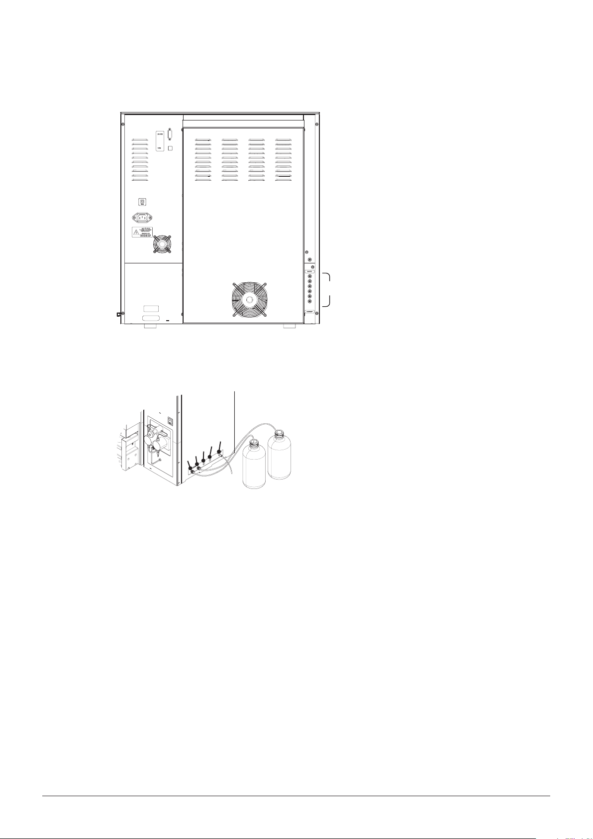
5.3 Gas and solvent connections
5 Putting into operation
• Connect nitrogen gas by means of the provided
hose. The corresponding joint contains a quicklock mechanism. The nitrogen gas connection
is located on the right hand side panel. The
required pressure range is 6 – 10bar. This
pressure has to be set at the external pressure
reduction valve.
• Connect the other end of the nitrogen line
to a nitrogen tank by means of the provided
1/8” Swagelok brass nut and ferrule
N
2
(P/N11055342).
• Connect the solvent reservoirs on the right hand
side panel. Make sure that the ferrule is pointed
towards the tting to avoid leaking, and ush
with the end of the tubing.
NOTE
Close vacant ports with a blind tting (P/N 035665) to avoid any unwanted contamination.
Never use technical grade solvent. It is strongly recommended to use p.a. quality or HPLC grade
solvents. To avoid contamination by the nitrogen use 5.0 quality for trace analysis and 4.5 for other
applications.
Risk of instrument damage by excess pressure within the instrument.
• Make sure that the maximum pressure of the nitrogen does not exceed 10bar
Risk of instrument damage by dry running instrument parts, especially valves.
• Never run the instrument or parts of it without any solvent
NOTICE
NOTICE
• Connect the EXHAUST and WASTE outlets on
the back of the instrument accordingly.
EXHAUST
WASTE
33 SpeedExtractor E-916 / E-914 Operation Manual
Page 35

5.4 Dehydration
NOTE
At initial start-up or after a long period of no use (>1month), the instrument should be dehydrated
for proper operation. To do so, heat up the instrument to 100°C for 1 hour (heater open, no cells).
Proceed as described in section 6.3.2.
5.5 Functional test
To make sure that the installation procedure has been carried out properly and the system is tight,
carry out a leak test (see section 6.2.5) before putting the instrument into operation for the rst time.
5 Putting into operation
34 SpeedExtractor E-916 / E-914 Operation Manual
Page 36

6 Operation
This chapter explains the operating elements and possible operating modes. It gives instructions on
how to operate the SpeedExtractor properly and safely.
The following table provides a quick overview of main step typically being involved in an extraction:
Overview of main step typically being involved
Step Action Section
1 Create a new method with default operating parameters 6.4.3
2 Preheat the instrument 6.2.3
3 Activate the positions 6.2.4
4 Flush the system (optional) 6.2.6
5 Activating the EcoMode (optional) 6.2.7
6 Prepare the sample 6.3.1
7 Select an extraction cell size 6.3.2
8 Pack the extraction cell 6.3.3
9 Insert the sample and collection vials 6 .4.1
10 Run the process 6.4.8
11 Optimize the process (optional) 6.4.7
12 Flush the system with the solvent used for the next run (optional) 6.2.6
6 Operation
6.1 Method development
A method must be developed before beginning an extraction to dene the operating parameters for a
run. When developing a new method it is often advisable to collect the extracts of the rst three cycles
followed by a vial change for the fourth cycle. If the second collection vial does not contain any analyte
the vial change is shifted between the second and third cycle. Depending on the amount of analyte
found in the second vials, optimization of the extraction time is recommended. For further information
regarding the vial change, see section 6.4.3.
Further information about how to optimize the extraction process is given in section 6.4.7. BUCHI's
SpeedExtractor Application booklet and Application notes give detailed information about method development and method parameters for a waste range of applications. Please contact your local dealer
or BUCHI for these documents.
35 SpeedExtractor E-916 / E-914 Operation Manual
Page 37

6.2 Preparing the instrument
This section involves all steps required to make the instrument ready for operation.
!
3
6.2.1 Solvent reservoir
Death or serious poisoning by contact or incorporation of harmful substances at use.
• Before operation, check the instrument for correct assembling
• Before operation inspect sealings and tubes for good condition and tightness
• Exchange worn out or defective parts immediately
• Provide sucient ventilation and make sure to directly withdraw fumes
6 Operation
WARNING
As already mentioned, when developing a new method, select a solvent or solvent mixture that is
already known from a classical method such as Soxhlet extraction or another high pressure method
such as ASE. Generally, the analytes should show high solubility in the extraction liquid, but not the
sample matrix.
Do not use solvents with an self ignition point of 40 to 220°C.
Particularly, do not use the following solvents with the SpeedExtractor. If there is any question about
solvent suitability, contact BUCHI.
Solvents NOT being compatible with the process
Component Formula Reason
Carbon disulde CS
Diethyl ether C4H10O Contains peroxide
1.4-Dioxane C4H6O Contains peroxide
Strong mineral or organic acids and bases Corrosive to metallic components
THF C4H8O Contains peroxide
Further aspects to consider:
• Use HPLC- or p.a. grade solvents.
• Generally, solvents do not need to be degassed; only if the analytes of interest oxidize easily.
• Weak acids and bases, such as acetic acid or potassium hydroxide, or other non-corrosive additives may be used in small portions, i.e. <5% by volume, added to the solvent system. Hydrolyzed
food samples for fat determination can be used without any problems since the hydrolysed residue is washed to a neutral pH prior to extraction.
2
Autoignition temperature 100°C
NOTE
Prior to an extended shutdown after an extraction ush the system (both INTO VIAL and INTO
WASTE):
• with chlorinated organic solvents for 2min with methanol
• with acidic or basic solvents with pure organic solvents such as ethanol or distilled water
See section 6.2.6 for a description of the ushing process.
36 SpeedExtractor E-916 / E-914 Operation Manual
Page 38

Never use technical grade solvent. It is strongly recommended to use particle free solvents such as
p.a. quality or HPLC grade solvent to guarantee proper operation of the valves, lters and frits.
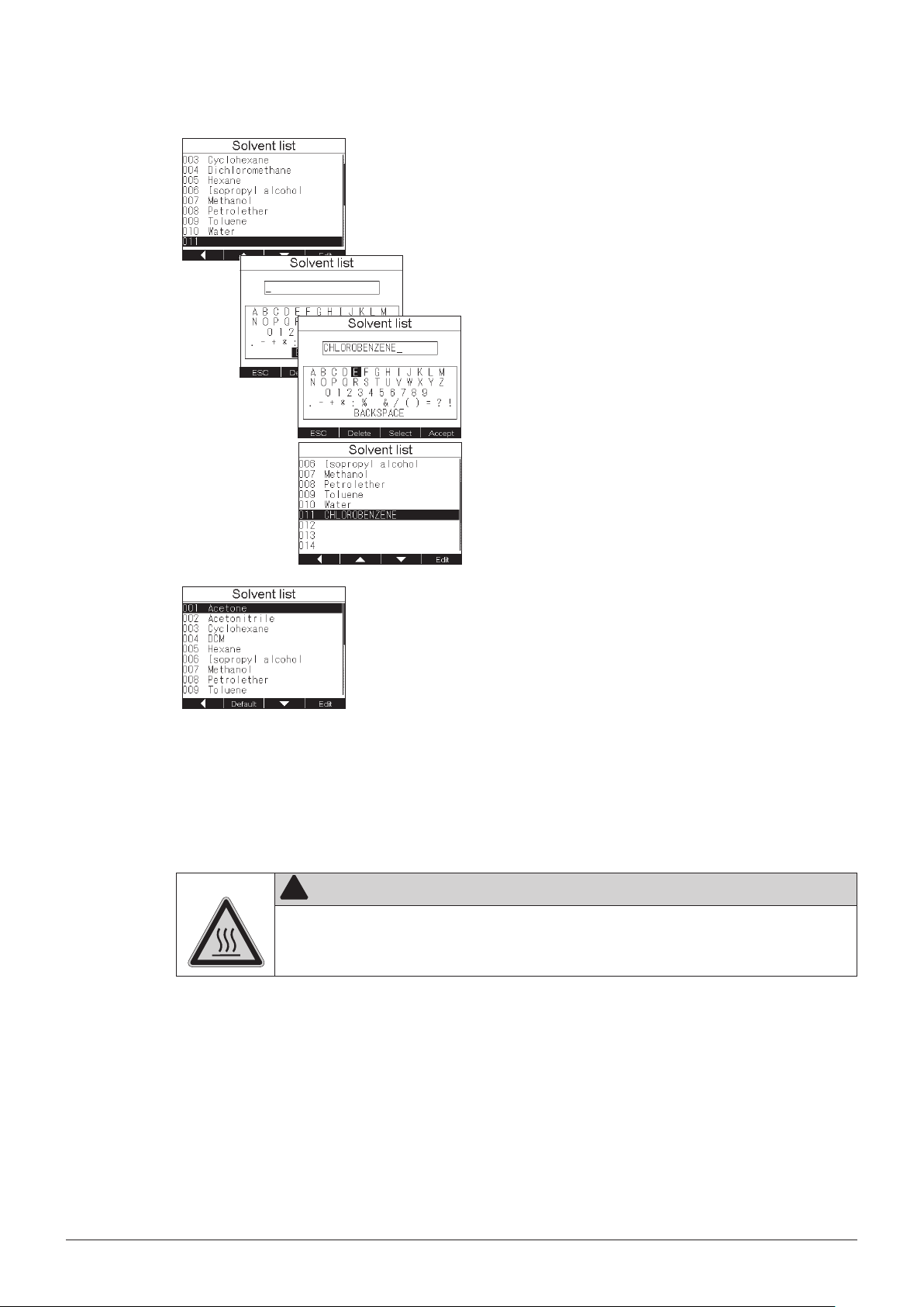
6.2.2 Modifying the SOLVENT LIST
When creating an extraction method (see section 6.4.3) the solvent used for extraction needs to be
determined. It is possible to create a list of up to 20 solvents for this purpose. The ten most frequently
used solvents are programmed in the SOLVENT LIST by default. However, this list can be expanded
or changed to include your own solvents or solvent mixtures.
6 Operation
Filling the solvent reservoir:
To prevent air from being drawn though the lines, insert
the inlet line (approx. 1m) equipped with an intake lter
(P/N 044340) into the reservoir until the lter touches
the bottom.
N
2
FILTER
Open the list:
• Go to MENU SOLVENT LIST to open the default
solvent list consisting of 10 entries.
Changing an entry:
It is possible to change the default solvent list as needed. For example, to change DICHLOROMETHANE into
DCM proceed as follows:
• Go to DICHLOROMETHANE and press EDIT. A
submenu with dierent characters appears. To erase
the whole name press DELETE. Move the cursor
to D using the selection knob and press SELECT.
Proceed similarly with C and M. To save the name
press ACCEPT. The modied name now appears on
the same position as previously Dichloromethane as
DCM.
• To modify a name (e.g. Dichloromethane_1) open
the EDIT menu, choose the corresponding characters and press SELECT. Conrm the changes with
ACCEPT. The modied name now appears on the
same position as previously Dichloromethane.
37 SpeedExtractor E-916 / E-914 Operation Manual
Page 39
6 Operation
Adding a new solvent:
• To add new solvents to the list go to an empty position (e.g. no. 11) and press EDIT. The editing display
is now empty. You can create your own names now
using the selection knob. For example: An extraction is performed with chlorobenzene which does
not belong to the standard list. Type CHLOROBENZENE as described above and press ACCEPT to
add the name to the solvent list. Chlorobenzene now
appears on position 011 on the solvent list.
6.2.3 Preheating the instrument
Preheating the instrument to the temperature of the subsequent extraction procedure is a mandatory
operation as it equilibrates the instrument and hence prevents the cells and cup seals from damage.
Risk of burns by hot heating block and extraction cells.
• Do not touch hot parts or surfaces
• Do not move the instrument or parts of it when hot
NOTE
Never preheat the instrument when the system is closed. Always equilibrate the instrument with
vacant positions rst.
!
CAUTION
Resetting the default list:
It is possible to reset the rst 10 entries back to the
default solvent list.
• Move the cursor to position 001. The move up
function button is now replaced by DEFAULT. Press
DEFAULT and conrm the message “Load default
solvent list? First 10 entries replaced”. The rst 10
entries are now replaced by the default solvent list.
The following entries (011 – 020) remain untouched.
38 SpeedExtractor E-916 / E-914 Operation Manual
Page 40

6 Operation
Setting the preheat temperature:
• Go to EXTRACTION PREHEAT to open the
preheat submenu. CURRENT METHOD indicates
the temperature setting of the current method. Use
COPY to copy this value in the preheat entry to heat
up the instrument to the temperature for the next
run. Alternatively, set a new temperature using the
selection knob.
Activating the ECO MODE:
The ECO MODE automatically turns o the heater
after the next extraction run. It is recommend that the
EcoMode be activated for unattended operation of an
extraction run (e.g. starting a last run overnight).
• Use the selection knob to tick the ECO MODE. For
more information see section 6.2.7.
Start heating:
• Press ON to start heating. The software goes
back to the main display where the temperature
slowly converges to the set temperature. To abort
preheating go to EXTRACTION PREHEAT and
press OFF. The red STOP button on the control
panel has no inuence on the preheat function.
NOTE
When the temperature of a previous run is higher than actually required by the subsequent extraction method, long cooling o times are required. Placing empty and cold extraction cells into the
heating block is a fast and eective measure to cool down a hot heating block to a lower temperature.
6.2.4 Activating/deactivating positions
Reducing the amount of solvent used for an extraction run is of vital interest. It is therefore possible to
deactivate unused positions. The position valve of a deactivated position remains closed throughout
the whole extraction process. Only the activated positions are ushed with solvent. It is important to
note that an empty extraction cell has to be placed into a deactivated position. This is to achieve uniform temperature distribution throughout the whole heating block and to make sure that the lift is not
at an incline when closed.
All extraction positions are deactivated by default. It is possible to activate all positions
together or each individually.
Preheat on demand:
Preheating the instrument is usually the rst task when
turning on the instrument. It is therefore possible to
congure the instrument so that PREHEAT submenu
appears as soon as the instrument is turned on.
• To activate this function open MENU INSTRUMENT SETTINGS. Go to PREHEAT DEMAND and
tick the function using the selection knob. Press OK
to conrm.
39 SpeedExtractor E-916 / E-914 Operation Manual
Page 41

6 Operation
Activate all positions together:
• Open EXTRACTION OCCUPIED POSITIONS.
Conrm “Occupy all positions?” with YES. The main
display shows all activated positions as numbered
cylinders.
Deactivate positions:
• To activate only the four middle positions, activate
all positions rst and then deactivate the positions 1
and 6. Go to EXTRACTION OCCUPIED POSITIONS and this time negate with NO. All positions
are deactivated now. Press ALL ON and move
the cursor to the vacant positions (in the current
example 1 and 6) and deactivate it by pressing OFF
or using the selection knob. The main display now
shows the vacant positions as crossed out cylinders.
NOTE
Never run the instrument with empty positions. In order to achieve uniform conditions, always place
identical empty extraction cells in the vacant positions. Therefore, using dierent sized extraction
cells in the same run is not recommended.
6.2.5 Leak test
The LEAK TEST feature allows the operator to check quickly and safely whether the instrument is
ready for operation. It is also a reliable measure to check the quality of the cup seals. A regular check
before operation is therefore recommended, and is mandatory after a longer period of non-use and/
or after replacement of the cup seals. There are two distinct approaches to perform a leak test. Firstly,
very commonly the tightness of the system is checked using the very same parameters as for the
subsequent extraction procedure. This allows the operator to evaluate the tightness on the basis of his
own operating parameters.
Secondly, in a more absolute approach the leak test is always performed using the same reference
settings. Thus, it is possible to reach conclusions on the basis of constant parameters. This is recommended in order to observe the long term behavior of the instrument, particularly of the seals or to
ensure correspondence on a method-independent basis, relative to the same set of parameters. In
contrast to a regular extraction method, to perform a leak test it is recommended to preheat the instrument with the extraction cells placed in the heating block for 15min to avoid thermal uctuations.
Common to both approaches is the sample and instrument preparation:
• Preheat the instrument with the extraction cells placed in the heating block. It is not necessary to
• Activate all positions (see section 6.2.4).
• Place empty collection vials into the collection rack and put it on the instrument as described in
equip the cell with the plug screw (see section 6.2.3 and 6.4.1).
section 6.4.1.
40 SpeedExtractor E-916 / E-914 Operation Manual
Page 42
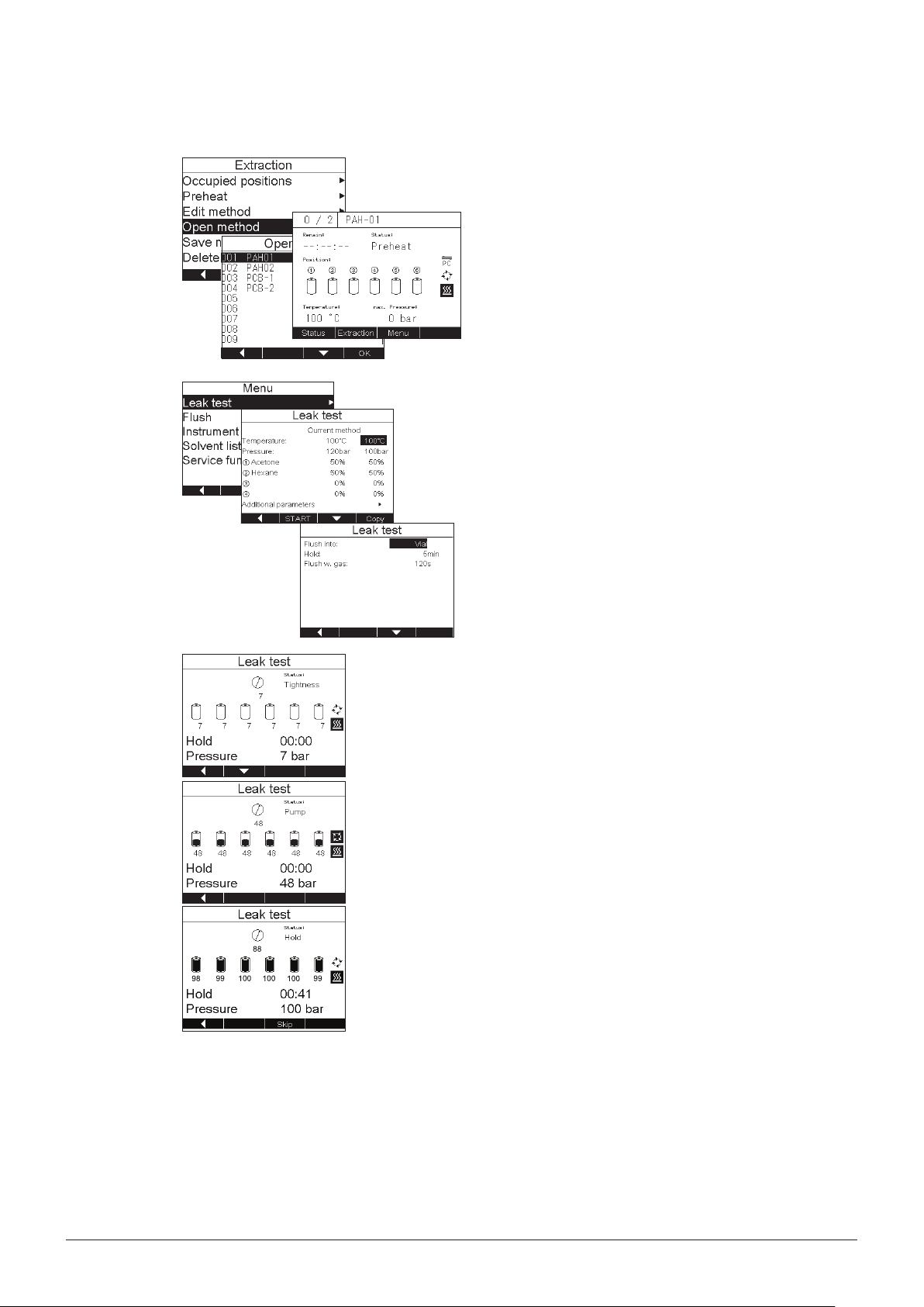
Method-based leak test
6 Operation
Open the method:
• Go to EXTRACTION OPEN METHOD and select
the requested method (e.g. PAH-01) and conrm
with OK. The name of the selected method now
appears in the main display.
Copy the parameters into the leak test:
• Open MENU LEAK TEST. The LEAK TEST menu
consists of two columns. CURRENT METHOD
includes all settings of the currently active extraction method (for instance PAH-01). SELECT shows
the parameters of the last used leak test. To copy
all parameters of the current method to the leak
test press COPY. The cursor skips to the next entry.
Proceed similarly for all entries.
• Under ADDITIONAL PARAMETERS the ushing
conditions can be set, i.e. the receptacle to ush
into, the hold time and the ushing time are dened.
Start the leak test:
• Pressing START on the function buttons (not the
green START button) closes the extraction cells and
starts elevating the pressure by pumping solvent
into the cells. A rst TIGHTNESS test checks the
presence of the extraction cells using nitrogen (see
section 6.4.2). The pressure remains constant at
7bar (pre-pressure) before it elevates the pressure
to the set value (for example 100bar) during the
PUMP step. In the hold step the position valves and
outlet valve are closed and the pressure is observed
over a constant time (approx. 5min). The pressure
of each position as well as the overall pressure is
shown below the extraction cell. In addition, the
maximum pressure is designated by PRESSURE.
The leak test is stopped after the set hold time is
elapsed. Alternatively, the process can be stopped
by pressing SKIP (not the red STOP button). The
outlet valve opens, the solvent is discharged and
the system is ushed with nitrogen. The measured
pressure remains on the display. The evaluation of
leak tests is described later in this section.
Standard leak test
The reference settings are used for the standardized leak test.
41 SpeedExtractor E-916 / E-914 Operation Manual
Page 43
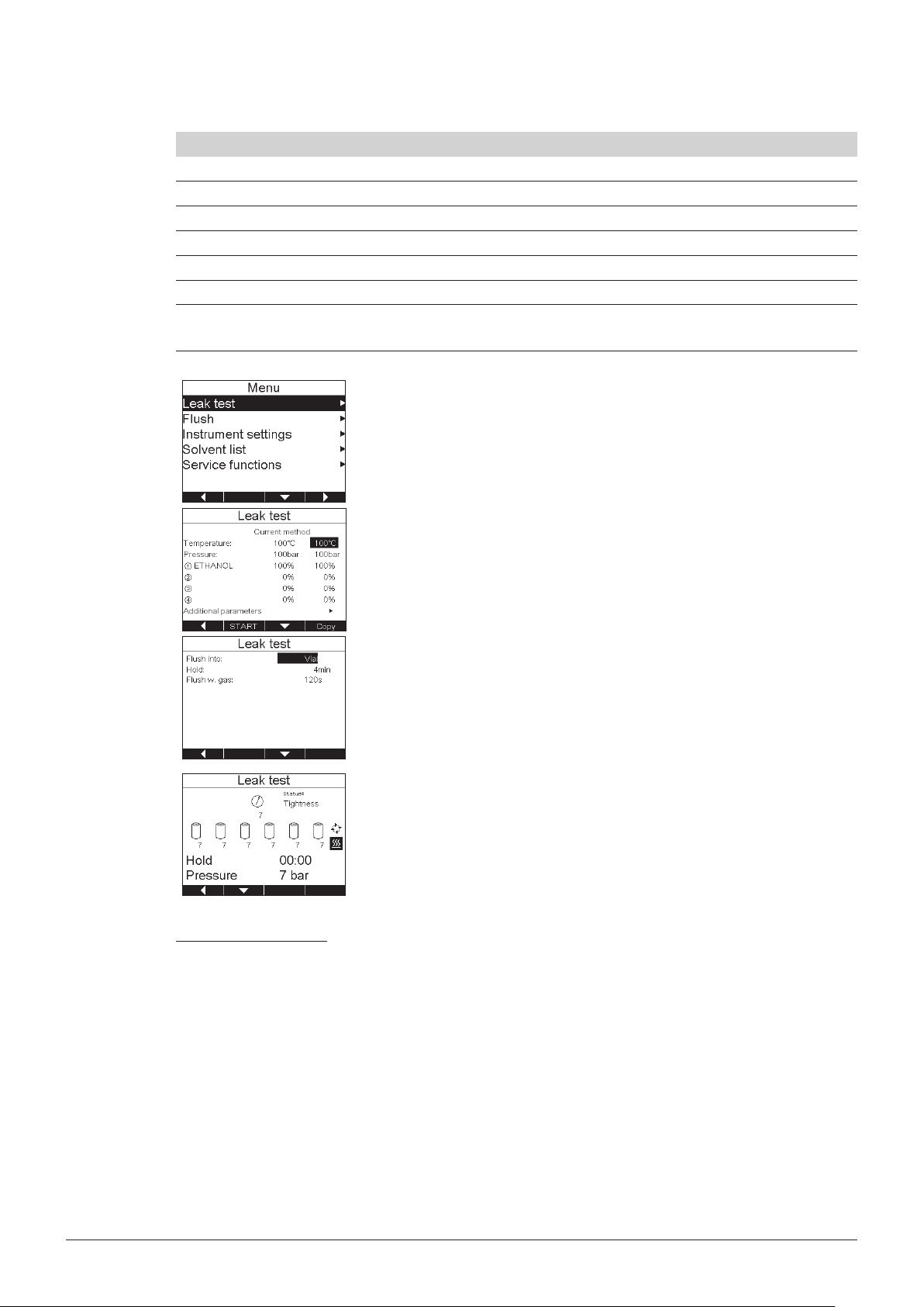
6 Operation
Reference setting for a standardized leak test
Description Value
Temperature 100°C
Pressure 100bar
Solvent ethanol
Hold time 4min
Extraction cell all volumes
Expansion element, sand Expansion element 2–120mL (refer to chapter10) or
sand
• Set the reference settings:
Open MENU LEAK TEST. Instead of copying the
entries of the CURRENT METHOD, set the reference settings according to the table above. For
the TEMPERATURE, set 100°C using the selection knob. Press OK. The cursor skips to the next
entry. Proceed similarly to set 100bar and 100%
ETHANOL.
Press START to run the leak test.
• As described for the method-based approach, the
presence of the cells is rst checked using nitrogen
(7bar) before the set pressure (100bar) is reached.
Evaluation of leak tests
The absolute values depend on dierent parameters. These are: Set temperature and pressure, used
solvent, cell size, and cell lling. When the following criteria are fullled, the instrument can be considered as tight and in good conditions:
• Maximum pressure dierence between the positions does not exceed 15bar.
• The pressure of the positions and the overall pressure has to be at least 95% of the set pressure.
• The overall pressure should drop after reaching the set pressure while the individual position
pressure(s) increases slowly. The overall pressure should not rise until the dierence between
overall pressure and position pressure(s) reached min. 25bar. After this the overall pressure is allowed to rise and to follow the position pressure(s).
42 SpeedExtractor E-916 / E-914 Operation Manual
Page 44

6 Operation
If the leak test shows that the SpeedExtractor is not tight, check the following options.
One or more positions have a lower pressure than the others:
• The drain valve is open close the valve (see section 8.1.3)
• The cup seals (bottom or top) are not tight anymore. The seals can be used for at least 100extractions, if not damaged mechanically by sand, sample, etc. check visually, replace the faulty
one (see section 7.2.2). If no damage can be seen due to a micro tear replace the bottom and top
seal and repeat the leak test.
The overall pressure is too high:
• The position valve might be defective. It is recommended to verify this hypothesis by re-do a leak
test, with only 2 positions activated. Choose therefor a position with the same or with a pressure
close to the overall pressure, and a position with a signicantly higher pressure. This second leak
test helps to identify the faulty valve. For exchange of a defective position valve, please contact
BUCHI Service.
• The check valves of the pump are clogged due to impurities clean the check valves (see section 8.1.5)
NOTE
Often a pressure increase of up to 10bar or more is observed in the hold step. This is because the
solvent and the cell are not heated up to the set temperature. In order to get good reproducible
results, it is therefore advisable to perform a leak test twice.
6.2.6 Flushing the instrument
NOTE
When using analytes with low detection limits, the instrument must be ushed thoroughly for 2min
with a suitable organic solvent to avoid carryover before the next extraction run.
When changing the solvent from one run to another it is
recommended that the lines be ushed with the solvent
used for the subsequent extraction. You can either ush
the solvent in the collection vials or the waste bottle. For
the latter the lines from the outlet valve to the collection
bottle are not ushed. However, placing the extraction
cells in the heating block is always mandatory. Flushing
with empty positions is impossible as the presence of
the cells is checked during the ush procedure.
It is always possible to switch to the STATUS view during the leak test if the dierent stages of the process
are of any interest.
Parameters E-916 E-914
Flush with solvent 120 s 180 s
Flow rate 5 0m L/ mi n 5 0 m L / m i n
Flush with gas 180 s 240 s
NOTE
Always use empty extraction cells to ush the system. Changing the solvent while the extraction cell
is lled, can result in extraction and hence contamination of the lines with matrix constituents.
In contrast to ushing during extraction (see section 6.4.2), the ow rate is not reduced in the FLUSH
43 SpeedExtractor E-916 / E-914 Operation Manual
Page 45

6 Operation
mode when positions are deactivated. This allows a fast and ecient ushing when using a reduced
number of positions.
Flush into waste:
• Open MENU FLUSH. Set the time to ush with
solvent. FLUSH INTO makes it possible to choose
between waste or vial. Choose WASTE using the
selection knob. Set the ow rate and ush with gas
according to the recommended parameter in the
table above. The CURRENT row in the SOLVENT
section shows the settings of the currently active
method. Press COPY to use these entries or set
new values using the selection knob. Press START
on the function button.
NOTE
The green START and red STOP button do not have
any inuence on the ush process. To stop the process
open the ush submenu again and press STOP.
NOTE
When changing the solvent reservoirs (e.g. from hexane to ethanol), take out the lter and rinse it
thoroughly with the new solvent to prevent contamination with the old solvent.
6.2.7 Activating the EcoMode
In the normal operating mode the instrument is ready for operation and therefore keeps the temperature constant at the level set in the PREHEAT menu. It is however possible to activate the EcoMode
which automatically turns o the heater once the current extraction is nished. It is recommended that
this mode be used for unattended last extraction runs such as overnight runs. By turning the instrument o and on, the EcoMode is automatically deactivated.
Flush into vial:
• Open MENU FLUSH and choose VIAL for the
FLUSH INTO entry using the selection knob. Set all
other parameters as described above and shown in
the reference settings table.
Activating the EcoMode:
• Open EXTRACTION PREHEAT. Move down to
ECOMODE with the corresponding function button
and activate it using the selection knob. There is no
need to conrm with ON. By simply ticking it the
ECOMODE is already activated.
NOTE
The EcoMode can also be activated while the last extraction is already running without interruption.
It is therefore not necessary to pause the process. Simply open the PREHEAT submenu and tick
ECOMODE.
44 SpeedExtractor E-916 / E-914 Operation Manual
Page 46

6.3 Preparing the sample
The following sections describe all operations being involved to prepare the sample for the actual
extraction process.
6.3.1 Sample preparation
To maximize extraction eciency, samples that are coarse, lumpy or rocky must rst be ground and/or
sieved to achieve a uniform particle size. Conversely, ne mesh samples may form tightly compressed
beds which restrict solvent penetration and impede solvent discharge. Such samples must be mixed
with a drying (diatomaceous earth) or dispersing (sand) agent before loading the extraction cell. If a
successful sample pretreatment procedure from another extraction method is known, also follow this
particular procedure for the Speed Extractor. However, for new samples the following guidelines may
be helpful:
• Dry samples work best, because water often tends to co-extract. Wet samples must be air or
oven dried before extraction. Wet samples reduce extraction eciency and may cause blowback
due to restricted ow through the sample bed. To dry and/or disperse samples, blend them with
diatomaceous earth (DE) (P/N 053201) or extraction sand (P/N 037689) in order to decrease
sample density, achieve uniform ow and increase analyte recovery. Generally, diatomaceous
earth dries samples more quickly than sodium sulfate and hence provides a cleaner transfer of the
mixture to the cell. On the other hand, sodium sulfate tends to clump the sample, making transfer
more dicult.
6 Operation
• The use of sodium sulfate with very wet samples (i.e. moisture content approx. 30%) may result in
recrystallization of sodium sulfate and hence clogging of the metal frit in the extraction cell. This is
the case particularly with solvent mixtures with acetone. In these cases blending the samples with
DE before loading into the extraction cell is highly recommended.
• Never use sodium sulfate with polar extraction solvents such as methanol, because this drying
agent is partly dissolved at the temperatures typically used for SpeedExtraction methods.
• For samples which are easily extracted particle sizes of 1 – 2mm provide generally good results.
For more critical samples particle sizes 500 μm are recommended.
• The material of the bottom lter (which is placed between the metal frit and the sample) may inuence the speed and eciency of the discharge and ushing step signicantly. The standard glass
ber lter is suitable for all applications. For samples with easy discharge and ush, the cellulose
lters (P/N 049569) can be an alternative.
NOTE
Consider the SpeedExtractor Application Booklet for general information about preparation of
dierent types of samples. It also includes application notes with reference settings for the most
frequently used application particularly in the environmental and food market. Sample types such
as polymers may soften or dissolve in solvent media such as dichloromethane and subsequently
extrude through the uid transfer lines resulting in plugged tubing and valves. Therefore it is recommended to use extraction thimbles. Additionally, some analytes are prone to precipitate after being
cooled down rapidly by passing the cooling unit. For critical samples it is therefore recommended to
use a smaller cooling unit instead (P/N 053682). Exchange of the cooling unit, however, requires an
authorized service technician. Please contact BUCHI or your local dealer.
45 SpeedExtractor E-916 / E-914 Operation Manual
Page 47
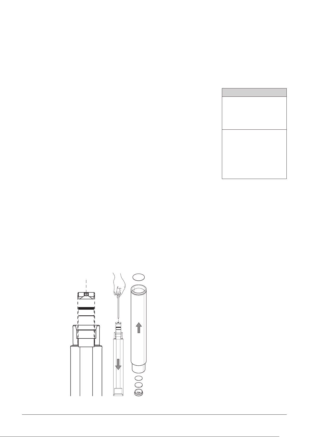
6.3.2 Extraction cell selection
NOTE
The process parameters are optimized to each type of extraction cell. Therefore, never mix extraction
cells of dierent sizes in the same run. Dierent cell sizes in the same run result in inhomogeneous heat
transfer.
6 Operation
There are various extraction cell sizes available, depending on the number of positions (see adjacent table). The size of the extraction cell does
not necessarily aect the extraction time during the HOLD stage, but it
does determine the time used to reach equilibrium (HEAT-UP stage; see
section 6.4.2), as well as the amount of solvent used for the method. As
the cell is lled with solvent during an extraction process, larger cells,
or only partially lled cells require more solvent. However, the same
method might require slight modications if performed with dierent
sizes of extraction cells. To optimize the amount of solvent, follow these
guidelines:
*Only Firmware Version 1.05 or higher
• Select the smallest cell that holds enough sample to produce accurate results.
• Take into account the volume increase resulting from drying or dispersing agents.
• For very small samples an expansion element may be used to ll up the void volume of partially lled
extraction cells (P/N 053708).
NOTE
This expansion element ts only 10mL extraction cells. The height of this cylindrical body is 2 cm.
Hence, one or two displacer can be used to ll up the remaining space, depending on the sample
volume.
Extraction cell sizes
SpeedExtractor E-916
• 10mL P/N 051237
• 20mL P/N 051236
• 40mL P/N 051235
SpeedExtractor E-914
• 10 mL 110679 88*
• 20 mL 110679 89*
• 40mL P/N 051234
• 80mL P/N 051233
• 120mL P/N 051232
6.3.3 Packing of the cells
A Insertion of the lower lter, metal frit and threaded plug screw
c
b
a
d
Put the extraction cell upside down (with the serial
g
number at the bottom) on a bench top and insert rst
a lter a of disposable glass ber (P/N 11055932) or
cellulose (P/N 049569) using tweezers. Place the lter
on the oset of the cell and make sure that it is in full
contact with the cell. The lter prevents blockage of the
metal frit and is therefore mandatory to use. The glass
ber lters are suitable for all application. They are required for fatty, ne powdery samples, for aqueous extractions and samples with remaining moisture, in order
to ensure an adequate ltration. They are also recommended for trace and ultra-trace analysis, as their use
results in lower blank values. For other samples and
solvents, the paper lter might be sucient too.
Place the metal fritb (P/N 049568) onto the lter and
a
close the bottom of the cell with the plug screwc (P/N
b
053209) using the plug screw toold (P/N 053607).
c
Make sure that the concave surface of the plug screw
points to the cell.
46 SpeedExtractor E-916 / E-914 Operation Manual
Page 48

6 Operation
Alternatively, use a paper or glass ber thimble to ll in your sample. The thimbles are recommended
for polymers and plastics (samples with tendency to melt during the extraction process) and sticky
samples, when not mixed with sand or diatomaceous earth. They are specially recommended for
the method development of the mentioned sample types. Glass ber thimbles are benecial for
gravimetric and residue determinations (lower blank value than paper thimbles).
NOTE
Close the plug screws hand tight. Over tightening the plugs can damage the cell. They are not
used to seal the cell but only to x the lter and frit in place.
B Insertion of the sample
Turn back the cell to its “regular” orientation (the frit
f
e
Alternatively, use a paper or glass ber thimble to load your sample. The use of thimbles is recommended for polymer samples and plastics with tendency to melt during the extraction process and
sticky samples, when not mixed with sand or diatomaceous earth. In particular they are recommended for method development in case of complex sample types. Glass ber thimbles are benecial for gravimetric and residue determinations with impact on lower blank value than paper thimbles.
NOTE
It is important not to ll the cell completely but to retain a void approx. 0.5 – 1cm in height between
the sample bed and the upper lter. This prevents the sample from clogging in case of swelling
and thereby guarantees uniform ow.
Dierently packed extraction cells usually require dierent amounts of solvent, because the dead
volume and back pressure are dierent.
is now at the bottom) and insert the metal funnele
into the oset of the cell (or the graduated line for the
largest cells; 40mL for the E-916 and 120mL for
the E-914). It is recommended to place the cells into
the cell rack for sample loading (E-916: P/N 053690;
E-914: P/N 053691) to provide more stability.
In order to carefully load the sample into the cell using
the optional weighing boatf (P/N 053202). Rinse the
weighing boat with some additional sand. If desired, ll
any cell void volume with additional sand or, in the case
of the 10mL cells, use the optional expansion element,
2mL (P/N 053355) to reduce the amount of solvent for
extraction.
47 SpeedExtractor E-916 / E-914 Operation Manual
Page 49

C Keep the sealing surfaces clean
6 Operation
Insert the upper celluloseg (P/N 049572 for
E-916, P/N051249 for E-914) or glass ber lter
(P/N11057189 for E-916, P/N 11057190 for E-914)
carefully uniformly into the cell using the plungerh.
The top glass ber lters are recommended for trace
and ultra-trace analysis. Again, visually inspect the cell
for remaining grains above the lter and make sure that
the lter is in full lateral contact with the cell.
NOTE
Do not attach any labels to the cell! The dimensions of
this assembly have been optimized to provide optimal
and uniform heat transfer from the heating block to
the extraction cell. Additionally, the high temperatures
might damage the label. For unambiguous sample
identication, every single extraction cell is etched
with a serial number.
D Insertion of the upper lter
h
g
g
Filters and frits
Filters and metal frits
• Bottom lter, cellulose (qty 100) 049569
• Bottom lter, glass bre (qty 100) 11055932
• Top lter E-916, cellulose (qty 100) 049572
• Top lter E-916, glass ber (qty 100) 1105718 9
• Top lter E-914, cellulose (qty 100) 051249
• Top lter E-914, glass ber (qty 100) 1105719 0
• Metal frit (qty 25) 049568
Extraction thimbles
• Thimble 40 mL cell, cellulose (qty 25) 11055334
• Thimble 40 mL cell, glass ber (qty 25) 1105 6 633
• Thimble 80 mL cell, cellulose (qty 25) 11059610
• Thimble 80 mL cell, glass ber (qty 25) 11059 612
• Thimble 120 mL cell, cellulose (qty 25) 110 55358
• Thimble 120 mL cell, glass ber (qty 25) 11059 611
Metal funnels
• E-916, 10mL cell 053035
• E-916, 20mL cell 053396
• E-916, 40mL cell 053397
• E-914, 40 - 120 mL cell
• E-914, 10 mL, 20 mL cells 110 67712
053036
NOTE
Be sure to clean the sealing surfaces at the top and the bottom carefully, i.e. the oset and the
surfaces above it. Use the brushes for that purpose. Any remaining sample or grain of sand reduces
the lifetime of the cup seals and the extraction cells signicantly. In case of proper operation the
seals last for 100 extraction runs.
48 SpeedExtractor E-916 / E-914 Operation Manual
Page 50
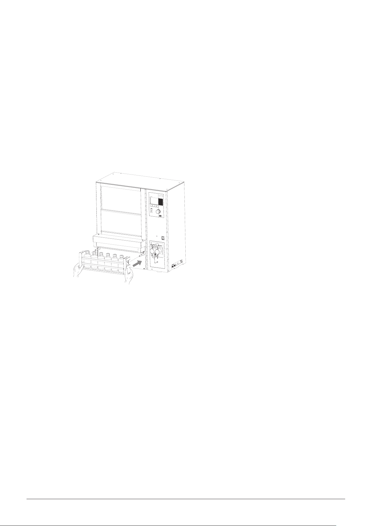
6.4 Extraction process
Each extraction procedure occurs according to a set of predened operating parameters such as
pressure, temperature, ow rates etc. which are all part of the extraction method. The SpeedExtractor
can store up to 100methods. The optional PC software SpeedExtractor Record allows to create and
manage an unlimited number of methods.
In order to guarantee reproducible conditions, it is recommended to make the instrument ready for the
extraction process as described in section 6.2, to prepare the samples in the meantime (section 6.2)
and start the extraction method as soon as the cells are placed in the heating element.
The following sections describe the individual stages of an extraction process, how to create, store
and open methods and how to optimize existing procedures.
6.4.1 Placing the cells and bottles/vials into the instrument
6 Operation
Fill the collection tray with empty vials and push it to
holding xture.
The tray will automatically move upwards as the
extraction process starts. If 60mL vials are used (P/N
049535) x the vials with the optional retaining plate
P/N 11055205 (see also section10).
If Syncore Analyst R-12 / R-6 vessels are used x the
vessels with the optional retaining plate P/N 11057054
for E-916 / R-12 and P/N 11058339 for
E-914 / R-6 (see section 10 for all available collection
units and accessories).
NOTE
The collection tray must be placed properly on the
instrument to start a method. It is not possible to start
a run in the absence of the tray.
Make sure to always ll the collection tray with empty
collection vials.
49 SpeedExtractor E-916 / E-914 Operation Manual
Page 51

6 Operation
The heating block is xed on movable guide rails.
This allows the operator to push the heating block
to the back to get easy access to the cup seals (for
inspection or exchange) and to pull it out to load the
extraction cells. Proceed as follows: Push the protective shield to the top and pull out the heating block as
far as possible. Use the extraction cell gripper (P/N
053030 for E-916, P/N 053026 for E-914) to place the
cells into the heating block. Move the heating block
backward until it snaps in the middle position.
Close the protective shield for safety reasons. The lift
does not move unless the shield is closed.
NOTE
In order to achieve reproducible results, never place
the extraction cells in the heating block before the
operating temperature is reached (equilibrium).
6.4.2 Stages of an extraction cycle
Generally, every extraction method consists of a number of cycles, which can be divided into 3
phases, the heat-up, hold and discharge time. Prior the rst cycle, the tightness test is carried out.
• Tightness test using nitrogen (checks, whether there is a cell in the activated position)
The tightness test is a quick initial check that veries whether the system is closed. In the event of
open outlet valves or empty positions in the heating block, the extraction run is aborted, and error
message is displayed.
The tightness test is not the same as the leak test (section 6.2.5). The leak test scrutinizes the leaking rate of each position and displays the corresponding pressures accordingly; it is not part of the
extraction method. On the other hand, the tightness test is an inherent element of each extraction
procedure and cannot be altered or modied in any way. It is essentially an internal safety procedure and is therefore not accessible to the operator.
• Heat-up time (heat-up of sample, solvent and cell)
In the time period between the tightness test and hold step the pressure is increased step-by-step
50 SpeedExtractor E-916 / E-914 Operation Manual
Page 52

6 Operation
to 1/3 and 2/3 of the nal pressure. The HEAT UP time is dened as the time during which the
pressure remains at 1/3 of the total pressure. A further prerequisite is that the temperature of the
heating block reached its equilibrium. It is a method-dependent intrinsic parameter which depends
mostly on the size of the extraction cell and is therefore not adjustable by the operator.
• Hold time
The hold time corresponds to the static extraction time during which the temperature and pressure
remains constant. This time period is only determined by the nature of the sample and hence set
by the operator.
• Discharge time
Time used to discharge the extraction cells by means of pressure compensation. Make sure the
time is long enough to empty the cell completely.
Close consideration of the process shown above reveals that there are two variable time periods
between the tightness test and the heat up and the heat up and the hold step, respectively. These periods depend on the process parameters, the sample's property and packing in the cell, and the size
of the extraction cell. The accurate values are therefore only available in hindsight. The remaining time
used to nish process which is shown in the main and the progress display, is based on rough estimations for these periods. Slight changes, observable by leaps in time, are therefore possible.
• Next cycle or Flushing the system
After the last extraction cycle is nished and the extract is discharged, the lines are ushed with
solvent rst, followed by nitrogen to thoroughly empty the lines. Make sure that the ush with solvent and gas are long enough to avoid carryover due to analyte residues of the last cycle (ush with
solvent) and to avoid a blow back of the sample due to solvent residues (ush with gas).
6.4.3 Creating new methods
A summarized overview of all extraction parameters as well as recommended default values are given
in section 6.4.4.
Open the submenu EDIT METHOD:
• To create a new method open EDIT METHOD in
the EXTRACTION menu. Use the selection knob
to set the values for the temperature and pressure
according to your procedure.
As a rule of thumb it is recommended to set the
temperature approximately 20 – 30°C over the
boiling point and the pressure to 100bar.
51 SpeedExtractor E-916 / E-914 Operation Manual
Page 53

6 Operation
Specify the vial volume:
• Specication of the volume of the collection bottle is
an important safety feature, since it alerts the operator if there is a conict with the total volume used
for the subsequently dened extraction volume. The
volumes of the most frequently used bottles (60mL,
150mL, 220mL and 240mL) are predened. If
using other volumes than the mentioned ones,
select “unspecied”. It is also possible to extract
into the waste. This option is made for applications
where the sample after extraction is of interest, not
the extract. Change the parameter using the selection knob.
Specify the cell volume:
• Specifying the volume of the extraction cell is
mandatory, because it has an inuence on some
process-related parameters, such as the heat-up
time. Change the parameter using the selection
knob.
NOTE
If the total extract volume gets too large and/or the
extract of dierent cycles are to collect separately,
insert a vial change in the method to exchange the
collection bottle between runs (see next paragraph).
Dene the solvent mixture
• Go to the SOLVENT submenu to choose a solvent
or solvent mixture according to the solvent list
previously adapted (see section 6.2.2) by either
pressing LIST or directly using the selection knob.
Press SELECT to select the solvent for your solvent
reservoirs and set the solvent ratio according to
your method. Proceed similarly with other solvents
if necessary. The NEXT button moves the cursor
forward to the next entry.
NOTE
The sum of the ratios must be equal to 100%.
If alternating solvents per cycle are used, choose
100% only for one solvent reservoir as the sum has to
equal 100%.
• The EDIT button allows you to directly modify the
solvent name without changing the solvent list.
Press ACCEPT to conrm the changes and switch
back to the EDIT METHOD display with the left
arrow.
52 SpeedExtractor E-916 / E-914 Operation Manual
Page 54

6 Operation
Dene the cycles:
• Specify the number of cycles and go to the CYCLES
submenu. The CYCLES submenu contains all cycles
including their operating parameters such as HEATUP, HOLD and DISCHARGE time. There are only
as many cycles shown as dened in NUMBER OF
CYCLES. All other entries are not applicable (n/a).
• To change parameters of a given cycle, move the
cursor to the corresponding cycle and press EDIT.
The new sub-submenu shows the number of the
cycle, the HEAT-UP time, which cannot be altered,
the HOLD time and the DISCHARGE time. Change
the entries using the selection knob. Move to the
next entry using the down arrow. Activate VIAL
CHANGE to exchange the collection vials between
the cycles to separately collect extracts of dierent
cycles or when the total volume of the extract
exceed the vial volume. In this case the warning “Vial
overow possible. Please validate vial size, cell size
and cycles.” appears. Conrm with YES and change
the parameters or include a vial change. But keep in
mind that this extends the total extraction time.
• Select the solvent for each cycle by using the selection knob. Solvent 1 – 4 correspond to the solvent
reservoir ports 1 – 4. Solvent 0 has to be selected,
if the extraction is done with a solvent mixture, see
section "Dene the solvent mixture". This option
allows to change the solvent from one cycle to the
other.
Flush with solvent/gas
• The time of the ush with solvent and ush with gas
can be entered by turning the selection knob. It is
mandatory to ush the system with gas for at least
1min (E-916) or 2min (E-914) respectively.
53 SpeedExtractor E-916 / E-914 Operation Manual
Page 55

6 Operation
Save the method:
• In order to save the modied new method, go
to SAVE METHOD back in the EXTRACTION
menu, select an empty position, and press OK.
Alternatively, choose an already occupied position to overwrite it. Modify the name in the ENTER
METHOD NAME window or write a new one by
pressing DELETE. To type a name, choose the
corresponding characters and press SELECT.
Conrm the changes with ACCEPT. The title of the
new, currently active method is now shown in the
header of the main display.
Up to 100methods can be saved in total.
NOTE
Changes on a currently active method are indicated by a crossed out title in the main display.
6.4.4 Summary of operating parameters
The following table summarizes the operating parameters required for an extraction method, their
function, and value range. Additional recommendations can be found in the corresponding Application
booklet.
Operation parameters
Parameter Function Value range
TEMPERATURE Dened set temperature used for the HOLD time. This value also
inuences the time used for the HEAT-UP.
PRESSURE Pressure inside the extraction cell during the HOLD time. 50 – 150bar
VIAL Size of the collection bottle. There are dierent vials avail-
able from BUCHI: at bottom narrow neck vials (60, 240mL) /
round bottom open neck vials (220mL) / Analyst vials (150mL)
/ unspecied vials (e.g. for the use of round bottom asks in
combination with the Rotavapor collection unit) and waste
CELL Size of the extraction cell. The options dep end on the instrument
conguration. It partially determines the HEAT-UP time.
SOLVENT Solvent mixture with which the extraction is performed. The
type of solvents connected to the solvent reser voir port s on the
right side of the instrument and their ratios are determined in a
submenu.
Save as
PAH-01
30 – 200°C
(default 100°C)
(default 100bar)
60, 150, 220, 240mL,
unspecied, waste
(default: 240mL)
E-916: 10, 20, 40mL
E-914: 10, 20, 40, 80,
120mL
list of 20 solvents
(default: 10 solvents)
54 SpeedExtractor E-916 / E-914 Operation Manual
Page 56

Operation parameters
Parameter Function Value range
6 Operation
TYPE Type of solvent in solvent reservoir 1 – 2 or 1 – 4 depending on the
instrument conguration.
RATIO Percentage of solvent 1 – 2 or 1 – 4 used to create the ex traction
method. The sum is always 100%.
NUMBER OF CYCLES How many times the HEAT-UP, HOLD, and DISCHARGE steps are
performed.
list of 20 solvents
(default: 10 solvents)
1 – 100%
sum: 100%
1 – 10
(default: 1)
CYCLES Involves all parameters relevant for an extraction c ycle. They are
accessible in a submenu.
HEAT-UP Time used for the HEAT-UP step. Parameters such as tempera-
xed
ture and size of the extraction cell determine the HEAT-UP time.
HOLD Time used for the extraction at constant temperature. 0 – 60min
(default: 2min)
DISCHARGE Time used to empty the extraction cells. This step is not
supported by nitrogen gas. Purging with nitrogen is achieved with
0 – 60min
(default: 2min)
the FLUSH WITH GAS parameter, which is not par t of the ex traction cycles but follows the last cycle.
VC Vial change. Option which makes it possible to change the collec-
tion vials between the cycles. The so lvent used in the last cycle is
,
(default: )
also used for the ush.
P Solvent selection of the used solvent port for each cycle. 1 – 2, resp. 1 – 4
(depending on con-
gureation), 0 = solvent
mixture (default: 0)
FLUSH WITH
SOLVENT
Time ushing with solvent. For the extraction method the ow
rate is adjusted automatically. The solvent used in the last c ycle is
0 – 9min
(default: 1min)
also used for the ush.
FLUSH WITH GAS Time ushing with nitrogen. 1, 2 – 30min
(default: 3min)
55 SpeedExtractor E-916 / E-914 Operation Manual
Page 57

6.4.5 Example of an extraction method
Example: Extraction of 6×5 g sample in 10mL extraction cells with acetone 50% and DCM 50%,
3×5min at 80°C and 100bar.
6 Operation
Procedure:
• Connect the solvent reservoirs to the corresponding ports: a: acetone, b: DCM
• Activate the extraction positions: EXTRACTION OCCUPIED POSITIONS YES.
• Flush with solvent (optional): Insert empty
extraction cells in all positions. MENU
FLUSH FLUSH INTO WASTE: Flush with
solvent: 120 s; ow rate 50mL/min; ush
with gas: 180 s; solvent: a: acetone 50%;
b: dichloromethane 50%. Remove the
extraction cells.
• Preheat: EXTRACTION PREHEAT: 80°C,
OK, ON. The oven starts heating.
6.4.6 Open an existing method
To open an existing method, proceed as follows:
• Create method: EXTRACTION EDIT
METHOD: Temperature 80°C; pressure
100bar; vial 60mL; cell 10mL; solvent
(see optional FLUSH); number of cycles 3;
cycles: hold 3min, discharge 2min, no vial
change (conditions apply for all 3 cycles);
ush with solvent 2min; ush with gas
3min.
• When the set temperature is reached, insert
samples and collection vials (60mL) and
close the protective shield.
• START
• Select OPEN METHOD in the EXTRACTION menu.
All saved methods (up to 100) are stored in a
numbered table. Select the desired method and
press OK. The name of the method now appears in
the title of the main display.
56 SpeedExtractor E-916 / E-914 Operation Manual
Page 58

6.4.7 Optimize a process
The following guidelines may help to optimize an extraction process in terms of yield and time.
Guidelines to optimize an extraction process
Action Advantage Drawback
6 Operation
Raising of the temperature
In general, raising the temperature increases the yield of the
extrac tion pro cess. However, particularly for temperature sensitive
compounds, it is advisable to keep this parameter rather low to
prevent degradation. Generally, temperatures of 20 – 30°C above
the boiling point provide good results. If oxidation is a concern,
degas the solvents prior to use, and close the solvent reservoir.
Multiple extraction cycles
Extending the hold time (see section 6. 2.4) enhances diusion of
the analytes into the extraction solvent to a certain ex tent. However,
using fresh solvent by introducing a new c ycle helps maintain a
favorable solvent/analyte e quilibrium, p ar ticularl y for s amples that
are heavily loaded.
High pressures for wet samples
For wet samples, higher pressures often provide better results in
terms of yield and extraction e ciency. This is mostly due to better
matrix penetration of the solvent and hence faster diusion of the
analyte from the matrix into the solvent.
Short extraction time (hold) for rst cycle
Particularly for saturated samples, a quick rst cycle is an eective
measure to prevent precipitation of the sample on the way to the
collection vials.
Short discharge and ush times
For optimization purposes it is advisable to use long discharge
times (i.e. 3min for E-916; 7min for E-914) and to determine the
time needed until no more drops are collected in the vial and to let
the pressure drop to 0-1bar. A shorter discharge time can then
be stored in the nal method. A similar approach is recommended
for the ush with gas time. To spe ed up the ush with gas, a SKIP
button appears after a dene d minimal safet y perio d, to move on to
the nal stage, given that the pressure is 0-1bar.
increased ex tra c ti on
eciency
increased ex tra c ti on
eciency
increased ex tra c ti on
eciency
no precipitation in
the lines
Shorter extraction
times
possible degradation
and/or oxidation
longer total extraction
times
possible clogging of
the sample as the
sample is high in
moisture
possible additional
extraction cycle
required
none
For more detailed information about method development and optimization, please consider BUCHI's
SpeedExtractor Application booklet and BUCHI's Application and Technical Notes. Please contact
your sales person or BUCHI for these documents.
57 SpeedExtractor E-916 / E-914 Operation Manual
Page 59

6.4.8 Start, pause, stop and abort extraction
Use the green START and the red STOP buttons to start, pause, abort, or interrupt an extraction process. These buttons are only applicable to the extraction process. All other procedures such as ush
or preheat are controlled by the function buttons (see also section 4.5.1).
• Start: Go to the main display and press START once. The START button is only active in the main
display.
• Pause: Press STOP once. The process is interrupted and can be continued by pressing START
again. Recommended action, e.g. the solvent reservoir is going to run dry or not connected.
• Abort: Press STOP twice. The process is aborted, the extraction cells are discharged and ushed
with nitrogen, and the collection rack and heating block are returned to their starting position.
Recommended action, e.g. if it turns out that the selected extraction method does not work properly.
• Abort immediately: Press STOP three times: The process is interrupted, and all assemblies remain
at their operating positions. All actions such as releasing the lift or opening the position valves, can
be controlled manually using the service menu. Recommended action in case of an unexpected
occurrence.
6 Operation
6.4.9 Post-extraction procedures
!
Risk of dangerous or moderate burns when handling hot extraction cells.
• Do not touch any hot parts
• Always use the gripper to move extraction cells
CAUTION
Cleaning the extraction cells
• After the extraction process is nished, open the
protective shield, pull out the heating block, and
take out the extraction cells using the extraction cell
gripper. It is recommended that the hot extraction
cells be placed into the rack (E-916: P/N 053690;
E-914: P/N 053691) to cool down the cells.
• Remove the upper lter using the lter hook (P/N
053316). Turn the cells upside down to get rid of the
sample mixture. Unscrew the plug screw. Remove
the sample using the extruder rod P/N 11055284.
Dispose of the lter, and clean the metal frit and the
plug screw in an ultrasound bath. Rinse the extraction cells with water or organic solvent, put them for
example in acetone (or a methanol/acetone/hexane
mixture) for 5 – 15min, and then put them in a dishwasher or oven. Do not exceed 300°C for the latter.
58 SpeedExtractor E-916 / E-914 Operation Manual
Page 60
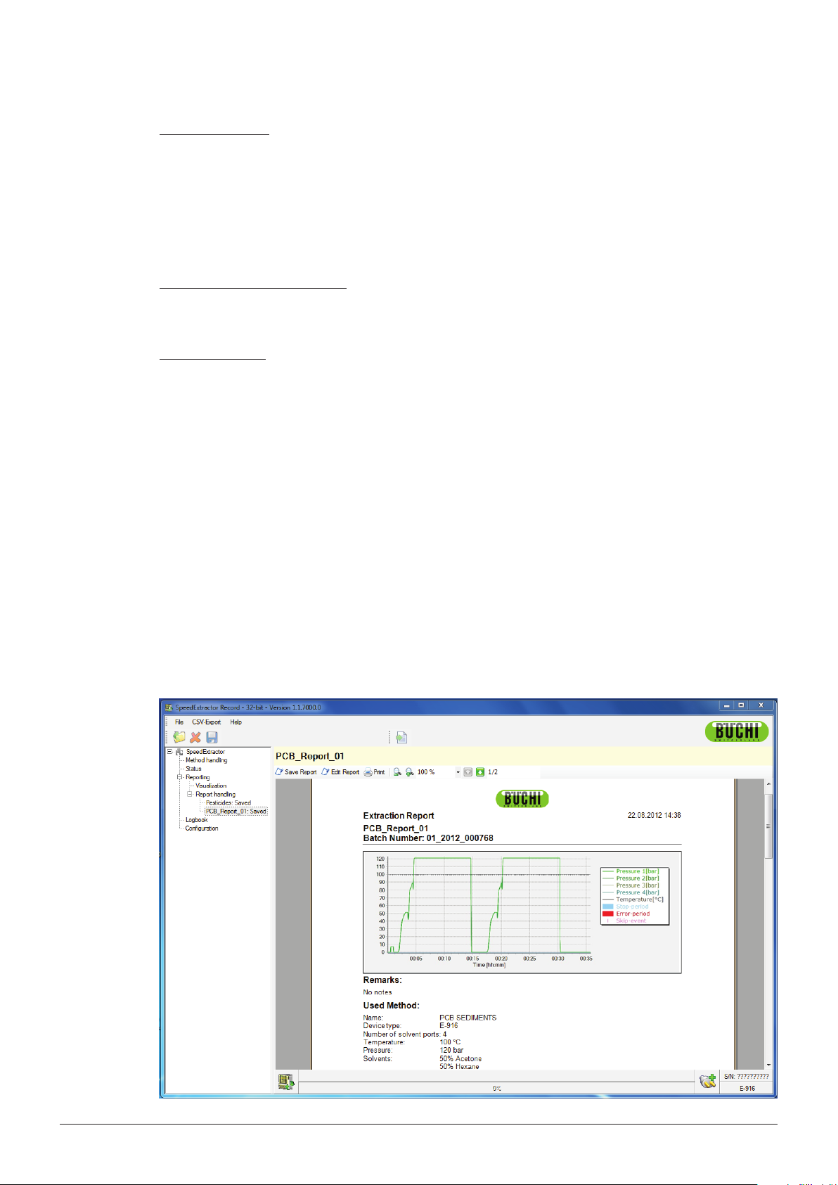
6 Operation
Cleaning the seals
• If necessary, rinse the seals with organic solvent (e.g. ethanol) with the help of beaker. Always
visually inspect the seals for dust, sand or scratches.
NOTE
Never clean the cup seals with a wet towel or wipe. Any kind of residue might cause a leak and/or
reduce the lifetime of the cup seals.
Cleaning the upper cup seal frit
• In case of unexpected contamination, remove the top cover plate (position 4 on page 95) and
clean it in an ultrasound bath.
Flushing the lines
• If the next extraction method involves a dierent type of solvent, ush the lines thoroughly with the
new solvent as described in section 6.2.5.
For further periodic maintenance procedures see section 7.2.
6.5 Creating a report (optional)
Optional PC software is available (P/N 053073), which allows communication between the SpeedExtractor and a PC via a USB port. The SpeedExtractor Record software allows you to fully create, edit,
and store extraction methods. It also includes a real-time status view of the SpeedExtractor. Moreover,
a visualization window graphically represents the temperature pressure sequence during extractions
and leak tests. All unexpected events like pause or vial change will be recorded. The logbook contains all relevant maintenance information about e.g. number of extractions or leak test information.
Finally, the process report feature generates full documentation, including all process parameters and
information, as well as the temperature/pressure proles, in PDF or CVS format. For more information
regarding the SpeedExtractor Record software, please refer to the corresponding manual on the free
trial CD (valid for 60 days) which is part of the scope of delivery (P/N053074).
59 SpeedExtractor E-916 / E-914 Operation Manual
Page 61

6 Operation
60 SpeedExtractor E-916 / E-914 Operation Manual
Page 62

7 Maintenance
This chapter provides instructions on all required maintenance to keep the instrument in good working
condition.
7 Maintenance
WARNING
!
Death or serious burns by electric current at cleaning.
• Switch o the instrument
• Disconnect the power cord and prevent unintentional restart
• Wait until the instrument is completely dry before reconnecting the power supply
7.1 Daily maintenance
Daily maintenance can prolong the system lifetime, reduce costs of service and downtime.
• Fill the solvent reservoirs according to section 6.2.1. Make sure that the lter is always completely
dipped into the solvent.
• Empty the waste bottle, if needed.
• Inspect the cup seals for visual damage or contamination by sand or dust. If necessary, replace
the seals according to section 7.2.1. Always perform a leak test after replacing the seals (see section 6.2.5).
• Check the nitrogen pressure (6 – 10bar).
• Check the septa of the collection vials.
• Inspect the needles for septa residue and/or deformation.
Cleaning the seals
• If necessary, rinse the seals with organic solvent (e.g. ethanol) with the help of beaker. Always
visually inspect the seals for dust, sand or scratches.
Risk of housing and instrument damage by liquids and detergents.
• Do not spill liquids over the instrument or parts of it
• Wipe o any liquids instantly
• Use ethanol or soapy water as detergent only
NOTICE
NOTE
Never clean the cup seals with a wet towel or wipe. Any kind of residue might cause a leak and/or
reduce the lifetime of the cup seals.
Cleaning the upper cup seal frit
• In case of unexpected contamination, remove the top cover plate (position 4 on page 95) and
clean it in an ultrasound bath.
Flushing the lines
• If the next extraction method involves a dierent type of solvent, ush the lines thoroughly with the
new solvent as described in section 6.2.6.
61 SpeedExtractor E-916 / E-914 Operation Manual
Page 63
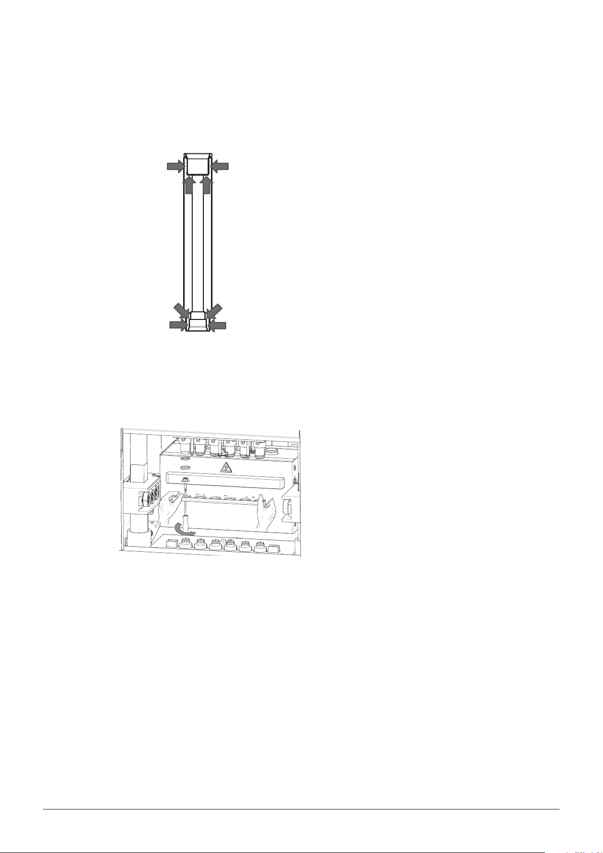
7.2 Periodic maintenance
7.2.1 Sealing system
7 Maintenance
The condition of the cup seals is crucial for the tightness of the system. Any kind of contamination on
either the sealing surface of the extraction cell or the
seal itself signicantly reduces the lifetime of the seals.
Therefore, always proceed as described in section
6.3.3 to ll the cell. Rinse the seals thoroughly with
organic solvent (e.g. ethanol) with a wash bottle and
a beaker to collect the solvent. With clean operation
the cup seals should last for approximately 100 runs.
In addition, make sure that cup seal holders are not
blocked by sand or dust. The holders need to be exible to seal the extraction cells properly.
NOTE
When replacing the seals, take care not to damage them. To avoid damaging the seals, never apply
grease and never touch them with sharp objects.
7.2.2 Replacing the cup seals
d
b
c
a
Replacing the upper cup seals
To replace the seals, push the heating block until it
is locked in the back position. Optionally, remove the
deectora. This is not mandatory to get access to
the cup seals. Unscrew the top cover plateb using the Torx screwdriverc (P/N 053668). The cup
seald can now be taken o manually and be replaced
(P/N053669 for E-916, 053671 for E-914). Be aware
of the upper brown PEEK ring. They easily get lost
when the cup seal is taken o. Proceed in reverse order to install the new seal. Make sure that the spring of
the seals always points to the extraction cell. Perform
a leak test to check the tightness of the system (see
section6.2.5).
62 SpeedExtractor E-916 / E-914 Operation Manual
Page 64

a
b
7 Maintenance
Replacing the lower cup seals
• To replace the lower cup seals, push in the heating
block until it is locked in the back position. Unscrew
the metal piecea manually and pull out the sealb.
NOTE
In contrast to the upper cup seal, no tool is required
for removal of the metal piecea.
• Replace the old seal with a new one (P/N 053670)
and proceed in reverse order to install the new seal.
Screw the metal piecea hand tight. Perform a
leak test to check the tightness of the system (see
section 6.2.5).
NOTE
The metal piecea has no sealing function whatsoever. Carefully screw it unto the stopper. Please
check the orientation of the cup seals. Make sure
that the spring always points to the extraction cell.
NOTE
Never remove the cup seals using your ngernails or any kind of tools, because that might damage
the seals or seal holder. With the help of plastic glove the seals can easily be turned and taken o.
7.2.3 Tube connections and needles
Visually examine the tube connections on a regular basis. All tubes which are accessible without opening the housing can easily be exchanged by the operator. For all other lines please contact your local
BUCHI representative.
b
c
spring
spring
a
Solvent reservoir connections
The FEP tubesa (OD 1/8”, ID 1/16”) are xed with
green ferrulesb and ttingsc (1/4 UNF-28, D 1/8”).
To reduce any dead volume and potential sources of
contamination, make sure that the ferrule is always
ush with the end of the tube. The pointed end of the
ferrule is oriented to the tting.
63 SpeedExtractor E-916 / E-914 Operation Manual
Page 65

7 Maintenance
Exhaust connections
A good indication for clogged needles or EXHAUST lines is a reproducible residual pressure of approx.
1 – 2bar after each run. In this case the lift does not open and an error message appears (see section 8.1.2). Other evidence for possibly clogged needles or lines is a dierence in receiving volumes
after ushing the system (see section 6.2.6). But note that there are other possible causes for unequal
solvent volumes after ushing such as bent needles or clogged frits.
NOTE
The ferrules can only be used once because they get deformed when the FEP tube is xed in place.
Replacement set (qty25): P/N 044816.
Waste connection
The FEP tubes (OD 1/16") to the waste are xed with gray ferrules and ttings (1/4 UNF-28 D 1/16"). To reduce any dead
volume and potential sources of contamination, make sure
that the ferrule is always ush with the end of the tube. The
pointed end of the ferrule is oriented to the tting.
Use the optional 7-port safety cap (P/N 11056948) to connect the waste tube with the waste container.
a
Gas connection
The line from the nitrogen tank to the instrument is
connected with quick-lock mechanism. To replace the
tube, make sure there is no pressure on the line, push
in the inner movable parta of the connector and take
out the tube. There are no items to be unscrewed. To
connect the new tube, push in the metal piecea again
and insert the new tube as far as it will go. Release the
parta. Check the tightness of the lines by closing the
media valve and pressure reduction valve on the nitrogen tank and observing the pressure decrease over
time. If there is constant leaking, inspect the tube and
connector and replace them if necessary.
64 SpeedExtractor E-916 / E-914 Operation Manual
Page 66

b
a
7 Maintenance
Needles
The needles need to be replaced regularly (i.e. at least
after every 6months) to reduce the risk of clogging
by particles of the septa or when they are bent. To
do so, remove the coversa andb. Unscrew the
needles with the wrench P/N 053204 and pull them
out from the bottom. Needles are available as sets of
12, P/N053675. Clogged needles can be cleaned with
thin wire.
NOTE
Make sure that the sloped sides of the two needles of
one position always point away from each other.
7.2.4 Septum
To reduce the risk of clogged needles and EXHAUST
lines, replace the septa of the collection vials regularly,
i.e. at least after every 5 runs.
Septum
Vessel Corresponding septum
Narrow-necked vials
qty 100, P/N 049536
(60, 240mL)
Wide-necked vials
qty 12, P/N 053677
(150, 220mL)
65 SpeedExtractor E-916 / E-914 Operation Manual
Page 67

7.3 Pump maintenance
d
f
Pump designations
a Mixer outlet line
b Pump inlet lines (left, right identical)
c Pump heads
d Pump outlet capillary left
e
e Pump outlet capillary right
f By-pass valve
7 Maintenance
7.3.1 Connections
c
c
b
b
a
FEP tubings
Use FEP tubing OD 1/8”, ID 1/16” for the mixer
outlet and pump inlet lines. Make sure that the ferrule
(P/N053664) is ush with the end of the tubing. After
the tubing has been prepared in this way, screw it into
the input block while continuously pressing the tubing
to the inside until the end of the tubing is rmly seated
on the bottom of the opening.
Outlet capillary
Unscrew the capillary from the outlet opening using a
¼” spanner wrench. Use 1/16” x 1mm outlet capillaries on which a ferrule and a screw are placed left:
P/N053613; right: P/N053614. In contrast to the FEP
tubing, the ferrule on the metal capillary should head
out of the screw. Screw the capillary prepared in this
way into the corresponding connection using a ¼”
spanner wrench while continuously pressing the capillary to the inside until the end of the capillary is rmly
seated on the bottom of the opening bottom.
66 SpeedExtractor E-916 / E-914 Operation Manual
Page 68

7.3.2 Back washing
Back washing is an important maintenance procedure when not only pure and ltered solvents are
used such as for example buer solutions.
7 Maintenance
The pump consists of two heads for alternate pumping and purging. They are both equipped with a Luer
cone in the upper part, into which a plastic syringe
(P/N034882) can be inserted as shown in the picture. Both heads are equipped with piston seals
(P/N053612). When operating with buer solutions,
there is a risk that buer crystals stuck on the piston
might damage the seal, causing the pump to begin
leaking.
Therefore, after termination of the operation, it is necessary to ush the lines and the pump vigorously with
clean solvent, which dissolves the buer, and, at the
same time, to wash the rear part of the piston in the
purging head.
67 SpeedExtractor E-916 / E-914 Operation Manual
Page 69

7 Maintenance
68 SpeedExtractor E-916 / E-914 Operation Manual
Page 70

8 Troubleshooting
The following chapter describes how to resume operation of the instrument in the event of any minor
problem. It lists some possible occurrences, their probable cause, and suggests how to remedy the
problem. The troubleshooting table below lists possible malfunctions and errors of the instrument and
describes operator-enabled courses of action to correct some of those problems. The appropriate
course of action is listed in the column “Remedy”.
More complicated malfunctions or errors are usually handled by a BUCHI technical engineer who has
access to the ocial service manuals. In this case, please contact your local BUCHI customer service
agent.
8.1 Malfunctions and their remedy
8.1.1 Action in case of a re
8 Troubleshooting
Abort the extraction process, close the safety shield of the ventilation hood and turn o the nitrogen
supply. Draw the re with a CO2 re extinguisher.
8.1.2 General malfunctions and their remedy
In the following table, X refers to the position in the heating block, starting from left to right.
General malfunctions and their remedy
Malfunction Display information Possible cause Remedy
Error 1 Not dened
Error 2 Heater temperature out of range
(DT > 30°C). Start not allowed.
Please refer to user manual.
Error 3 Heater temperature out of range.
Start anyway?
Error 4 Change vials. The collection vials need to be
Preheating has not yet reached
the set temperature of the
method. Ex traction or leak test
cannot be started.
Occurs when the previous
method was run at a higher
temperature than the current
one. The oven temperature is too
high (i.e. DT > 3°C higher than
the set temperature).
changed, because collection
of the next cycle would cause
overow (see section 6.4.3).
Wait until the instrument has
reached equilibrium. Take out the
extraction cells if the temperature is far out of range. If this
occurs frequently, contact BUCHI
customer service. The heater
may have a problem.
Wait until the instrument has
cooled down to the set temperature to achieve equilibrium and
reproducible conditions. Cooling
may be accelerated by placing
cold cells into the heating block.
Switch back to sample cells
when the set temperature is
reached. Alternatively, extraction or leak test can be started
anyway if reproducibility is not
so important.
Replace the vessels in the collection tray with empty ones.
69 SpeedExtractor E-916 / E-914 Operation Manual
Page 71

General malfunctions and their remedy
Malfunction Display information Possible cause Remedy
Error 6 Heater timeout. Temperature not
achieved. Please refer to user
manual.
Temperature is not within ±3°C
of the set temperature after
60min preheating time.
Acknowledge the message and
wait until the temperature is
reached. If this occurs fre quently,
contact BUCHI customer service.
The heater may have a problem.
Error 7 Method not complete. Parameters of the extraction
method are not den e d, resultin g
in an ambiguous method that is
not reproducible.
Complete the extraction method
in the EDIT METHOD menu and
save again. See also section
6.4.3.
Errors related to the motor lifting the heating block.
Error 8 Light barrier malfunction cell lift.
Please refer to user manual.
Error 9 Heating block not in star t posi-
tion. Please bring heating block
to start position.
Error 10 Shield not closed.
Please close shield.
Err or 11 Power consumption of cell lift
motor too high. Please check if
heating block is b locked . Please
refer to user manual.
Er ro r 12 Target position of heating bl ock
not achieved. Please check if
heating block is b locked . Please
refer to user manual.
Er ror 13 Cell lift motor blocked. Please
refer to user manual.
The light barrier is disconnected
Contact BUCHI customer service.
or covered.
Heating block is not properly
placed in the middle position.
Move the heating block forward
or backward until it snaps in
place. See section 6.4.1.
The cell lift will not move as long
as the shield is open.
Close the shield and press
START again.
The lif t is mecha nically b locked . Inspect the lift for physical
blockage. Contact BUCHI
customer service if the problem
persists.
The lift does not reach its nal
Contact BUCHI customer service.
destination within a given time
because of a motor or light
barrier problem.
The lift does not move at all,
Contact BUCHI customer service.
most probably due to a faulty
v-belt or motor.
Error 14 No power consumption of cell
lift motor. Please refer to user
The motor is either disconnected
or damaged.
Contact BUCHI customer service.
manual.
Errors related to the motor lifting the collection rack.
Error 15 Light barrier malfunctio n vial lif t .
Please refer to user manual.
Error 18 Power consumption of vial lift
motor too high. Please check if
vial rack is blocked. Please refer
to user manual.
Error 19 Target position of vial rack not
achieved. Please check if vial
rack is blocked. Please refer to
user manual.
Error 20 Vial lift motor blocked. Please
refer to user manual.
The light barrier is disconnected
Contact BUCHI customer service.
or covered.
The lif t is mecha nically b locked . Inspect the lift for physical
blockage. Contact BUCHI
customer service if the problem
persists.
The lift does not reach its nal
Contact BUCHI customer service.
destination within a given time
because of a motor or light
barrier problem.
The lift does not move at all most
Contact BUCHI customer service.
probably due to a faulty v-belt or
motor.
8 Troubleshooting
70 SpeedExtractor E-916 / E-914 Operation Manual
Page 72

General malfunctions and their remedy
Malfunction Display information Possible cause Remedy
Error 21 No power consumption of vial
lift motor. Please refer to user
The motor is either disconnected
or damaged.
Contact BUCHI customer service.
manual.
Errors related to pressure sensors or pressure in general.
Error 22 Calibration of pressure sensor
not successful. Please refer to
user manual.
Error23
to
error28
Error29
to
error34
Calibration of pressure sensor
Cell X not successful. Please
refer to user manual.
Cell X clogged: press START
to disable position or repeat to
discharge.
A pressure sensor is defective. The defective pressure sensor
needs to be replaced. Contact
BUCHI customer service.
The pressure sensor at position
X is defect.
The defective pressure sensor
needs to be replaced. Contact
BUCHI customer service.
The pressure at position X after
discharge is too high (between
1and 80bar).
Press REPEAT to discharge
again. If the error message
occurs again, follow the instruc-
tions outlined in section 8.1.3.
8 Troubleshooting
Error35
to
error40
Position X clogged: press repeat
to discharge or relieve the pressure manually. Please refer to
user manual.
Error 41 Several positions are clogged:
please repeat to discharge, or
relieve the pressure manually.
Please refer to user manual.
Error 42 A clogging occurred during
extraction. D o you want to open
the cell lift? Alternatively, relieve
the pressure manually.
Error45
to
error50
Position X: Pressure too low.
Please check whether a cell is
inserted. Please refer to user
manual.
The pressure at position X is too
high (>80bar).
Error 41 o ccurs when more than
one position is clogged.
Error 42 always occurs at the
end of an extraction process
when clogging occurre d befo re
(error 29 – 41).
Not all activated positions are
occupied with an extraction cell.
Press REPEAT to discharge
again. If the error message
occurs again, follow the instruc-
tions outlined in section 8.1.3.
Press REPEAT to discharge
again. If the error message
occurs again, follow the instruc-
tions outlined in section 8.1.3.
Follow the instructi ons outline d
in section 8.1.3.
Pull out the heating block and
occupy the vacant positions.
NOTE
It is generally recom-
mended to accommodate
all positions to achieve best
reproducible results. See
also 6.2.4.
71 SpeedExtractor E-916 / E-914 Operation Manual
Page 73

General malfunctions and their remedy
Malfunction Display information Possible cause Remedy
Error 51 Pump pressure too high. Please
refer to user manual.
During Extraction
The pump is purging against
a closed system, i.e. a closed
valve.
Check the state of the media,
position and outlet valve. Open
the corresponding valve(s) in the
SERVICE FUNCTIONS > VALVE
menu. Calibrate the rotating
valves (media and outlet valve) if
necessary.
During LEAK TEST:
Calibration procedure:
8 Troubleshooting
Error52
to
error57
Position X: Pressure too high.
Please refer to user manual.
Press OK to conrm the error.
The cell lift will open and the
LEAK TEST is nished. Calibrate
the pressure sensors to correct
the error!
During Extraction
The pressure at position X is
too high, most probably due to
clogging of the sample in the
extraction cell during operation.
During LEAK TEST:
Press OK to conrm the error.
The cell lift will open and the
LEAK TEST is nished. Calibrate
the pressure sensors to correct
the error!
Enter the SERVICE FUNCTIONS
> VALVE menu and open the
position and outlet valves.
To calibrate the pressure sensors
enter the SERVICE FUNCTIONS
> SENSORS menu. Press NEXT
and start calibration by selecting
CALIBRATE.
Close all corresponding valves
again. Re-run the LEAK TEST to
verify the calibration!
Relieve the pressure manually by
opening the drain valve. Follow
the instructions outlined in
section 8.1.3.
Calibration procedure:
Enter the SERVICE FUNCTIONS
> VALVE menu and open the
position and outlet valves.
To calibrate the pressure sensors
enter the SERVICE FUNCTIONS
> SENSORS menu. Press NEXT
and start calibration by selecting
CALIBRATE.
Close all corresponding valves
again. Re-run the LEAK TEST to
verify the calibration!
Error 58 No position selected. Please
select at least one position.
The positions accommodating
the samples are not selected.
Select the corresponding
positions: EXTRACTION
OCCUPIED POSI TIONS. See also
section 6.2.4.
Error 59 Nitrogen inlet pressure out of
range. Please check nitrogen
supply.
Nitrogen tank is not connected
or empty.
Check the pressure and connec-
tion of the nitrogen tank. See
also section 5.3.
72 SpeedExtractor E-916 / E-914 Operation Manual
Page 74

General malfunctions and their remedy
Malfunction Display information Possible cause Remedy
Error61
to
error64
Solvent valve X: Does not close.
Please refer to user manual.
The solvent valve X or connection to the valve is faulty and
needs to be exchanged or
repaired.
Connect the solvent bottle to a
dierent port (if possible) and
manually select the new position
in the menu EXTRACTION
EDIT METHOD SOLVENT.
Contact BUCHI customer service
to exchange the defective parts.
Error 66 Pressure not reached. Pump
timeout. Please check solvent
reservoir. Please refer to
user manual.
The set pressure is not reached
within a given time period.
The most probably causes are
an empty solvent reservoir, a
clogged lter, an interruption
Depending on the caus e p ro cee d
as follows:
– Fill the solvent reservoir
– Clean the lter
– Replace the solvent lines.
in the solvent connection, or a
severe leak. In the latter case,
this can be heard and in most
cases can be smelled.
Try to locate the leak. If obvious
remedies, such as replacing
a seal do not get anywhere,
contact BUCHI customer service.
Error 67 No communication with pump.
Please refer to user manual.
Error68
to
Position valve X: Does not close.
Please refer to user manual.
error73
The pump is not supplied with
current.
The position valve X or the
connection to the valve is faulty
and needs to be replaced or
Contact BUCHI customer service.
Contact BUCHI customer service.
repaired.
Error 74 Target position of media valve
not achieved. Please refer to
user manual.
The media valve or connection to
the valve is faulty and needs to
be replaced or repaired.
Calibrate the media valve as
described in section 8. 2.1. If the
problem remains, contact BUCHI
customer service.
Error 75 Target position of outlet valve
not achieved. Please refer to
user manual.
Error 76 Pump pressure out of range.
Please refer to user manual.
The outlet valve or connection to
the valve is faulty and needs to
be replaced or repaired.
The overall pressure sensor
(located between media valve
Contact BUCHI customer service.
Contact BUCHI customer service.
and divider) or connection to the
sensor is faulty and needs to be
replaced or repaired.
Error77
to
error82
Position X: Pressure out of range.
Please refer to user manual.
The pressure sensor located
between the position valve and
extraction cell is faulty and
Contact BUCHI customer service.
needs to be replaced.
8 Troubleshooting
73 SpeedExtractor E-916 / E-914 Operation Manual
Page 75

8.1.3 Handling and resolving blockages
When a position gets clogged, the pressure is not relieved when the outlet valve opens and discharges the extract. As a result, the pressure remains high in this clogged position. This entails two
problems: Firstly, there is a possible chance of cross contamination between the pressurized clogged
position and the adjacent low pressure positions during the heat-up step of the subsequent cycle.
Secondly, the cell lift does not open when the process is nished to avoid splashing of the sample.
There are dierent reasons why blockages can occur during extraction under high pressure and high
temperature using the SpeedExtractor E-916 / E-914: inappropriate sample preparation, extraction
parameters, or instrument conguration. Often a combination of these factors can cause blockages.
• An appropriate sample and cell preparation is important to avoid blockages. The use of glass ber
lters and/or thimbles is recommended for sticky, ne powdery and polymer samples. See section6.3.
• An optimized method is essential. Control the following parameters: temperature, solvent, numbers of cycles and hold time. Too high temperatures can lead e.g. to melting of polymer samples.
A short rst cycle can be helpful for samples with high concentration of analyte (e.g. fat in food
samples). For more detailed information about sample preparation and method development,
consider BUCHI's Application Notes, Technical Notes and the SpeedExtractor Application Booklet. Please contact your local representative or BUCHI for these documents.
• Some samples are prone to precipitate upon passing though the cooling unit during the discharge
step. The shorter cooling unit (P/N053682) does not cool down the sample that much and hence
reduces the risk of precipitation.
8 Troubleshooting
NOTE
The method development of a new unknown sample should be carried out on only one position,
preferably position 1. If it is necessary to replace parts for cleaning, position 1 is the position which
can be reached most easily. If a clogging occurs during the method development step, it is possible
to continue with further extractions using the remaining positions.
At the end of the discharge step pressure sensors at the activated positions will check if the pressure is released before continuing with the next step (another cycle or ush with solvent or gas). If the
pressure has not been released to <1bar, an error message will be shown and the operator should
then follow the instructions. Following the error messages, it will be necessary to release the pressure
manually.
Relieving pressure manually
Open the drain valve manually using the bit wrench P/N052783. Opening the drain valve results in a
hot steam of solvent for a quick moment. In order to prevent possible splashing, open the safety shield
and put a towel around the clogged position. Close the drain valve and the shield when nished.
74 SpeedExtractor E-916 / E-914 Operation Manual
Page 76

8 Troubleshooting
CAUTION
!
Risk of minor or moderate injuries by hot steam of solvent when opening the drain valve.
• Use a towel or insulated gloves for protection
There are three cases to distinguish depending of the pressure in the clogged position and the number of clogged positions. In the following paragraphs, the work ows of the dierent scenarios are
explained with ow charts.
Pressure <80bar in clogged position (Errors 29 – 34, see section 8.1.2 for error messages)
In the ow chart is shown that the SpeedExtractor will be in the “wobble position”. This means that the
heating block is slightly moving up just to increase the volume inside the extraction cell. The position is
still tight, but the pressure will be decreased due to the larger volume now inside the cell.
75 SpeedExtractor E-916 / E-914 Operation Manual
Page 77
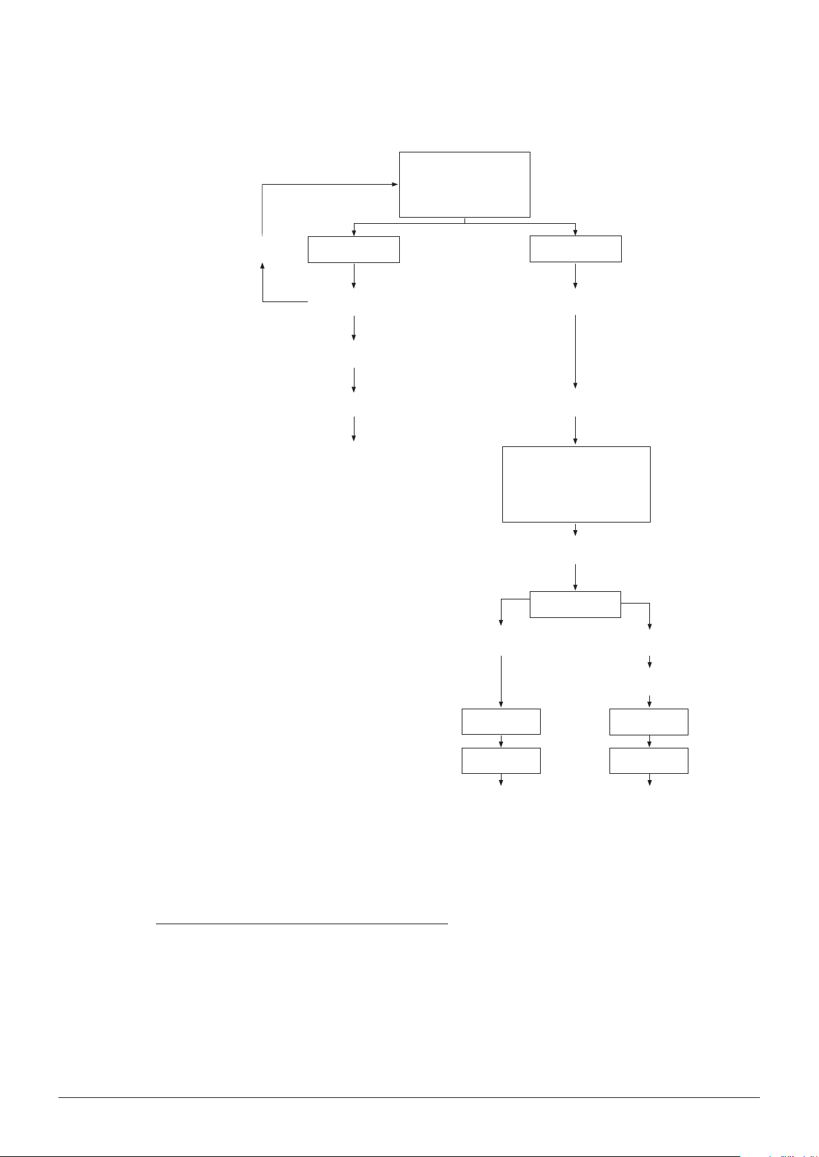
Error 29 – 34
Position X clogged: press START
to disable position or repeat to
discharge
8 Troubleshooting
no
Repeat
Pressure released?
yes
Extraction with all posi-
tions
End: heater opens
A clogging occurred during extraction. Do
you want to open the cell lift?
Alternatively, relive the pressure manually.
p < 1bar
START
Wobble position: position
is disabled
Extraction with other
positions
Error 42
Control of pressure in
STATUS
p > 1bar
Relieve pressure
manually
Error 42
START
End: heater opens
Error 42
START
End: heater opens
Pressure >80bar in clogged position (Errors 35-40)
If the pressure in the position is above 80bar, the instrument will not be in the “wobble position”. This
means that the heating block is not moving and the pressure will not decrease automatically, and so
must be released manually, see above. "//" indicates that it does not make sense to follow this way
due to moving in circles.
76 SpeedExtractor E-916 / E-914 Operation Manual
Page 78
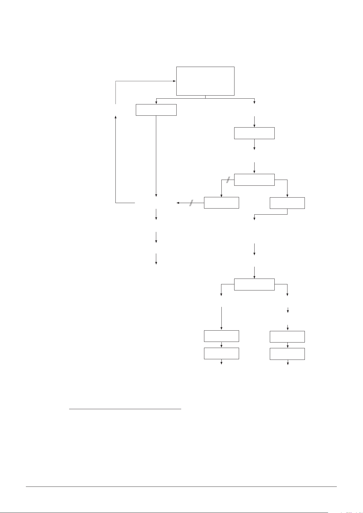
Error 35 – 40
Position X clogged: press repeat to
discharge or relieve the pressure
manually.
8 Troubleshooting
no
Repeat
Pressure released?
yes
Extraction with all posi-
tions
End: heater opens
Control of pressure in
STATUS
Relieve pressure manually
Error 35 – 40
repeat
No wobble position; position is deactivated. Extraction of other positions
Control of pressure in
STATUS
START
p < 1bar
Error 42
START
End: heater opens
p > 1bar
Relieve pressure
manually
Error 42
START
End: heater opens
More than one position is clogged (Error 41)
Once the SpeedExtractor has shown the error messages 29 – 34, 35 – 40 or 41 and the pressure is
released following the instructions given in the ow charts, it is then necessary to locate the blockage.
To do so, insert empty cells without lter papers, metal frits and plugs in the positions in question.
Start a ush into the collection vials (see section 6.2.6). If solvent ows into the vials, the cell (sample
inside the cell, the lter or frit) was blocked. If solvent does not ow into the vial, the SpeedExtractor is
blocked and further steps are necessary.
77 SpeedExtractor E-916 / E-914 Operation Manual
Page 79
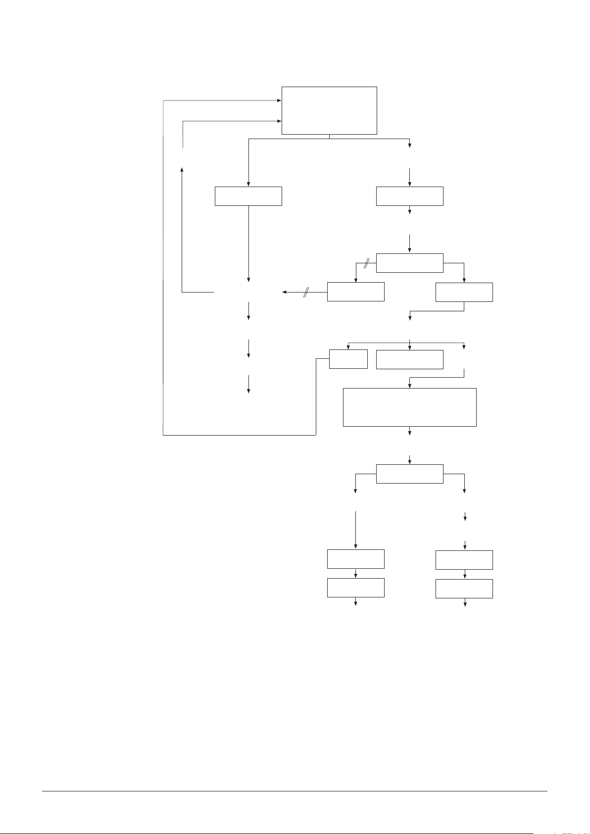
8 Troubleshooting
End: heater opens
Position X clogged: press repeat to
discharge or relieve the pressure
no
Repeat
Pressure released?
yes
Extraction with all posi-
tions
Error 41
manually.
Control of pressure in
STATUS
Relieve pressure manually of all
clogged positions
Error 41
repeat
One position is deactivated, extraction of
other positions continues
Error 41
Error 29 – 34
START
No error
Error 42
manually
Control of pressure in
STATUS
p > 1bar
Relieve pressure
manually
Error 42
START
End: heater opens
A clogging occured during extrantion. Do you want to
open the cell lift? Alternatively, relieve the pressure
p < 1bar
Error 42
START
End: heater opens
Blockages may be pushed out under extreme conditions. Therefore an extraction with the following
conditions should free the lines.
• Extraction conditions: temperature 200°C, pressure 150bar, 1 cycle, hold 10min, discharge
5min, ush with solvent 2min and ush with gas 5min. Use the same solvent, cell and vial size as
for the extraction when the blockage appeared.
• If the SpeedExtractor is still blocked after this extraction it will be necessary to identify the
blocked part. The ow test in the service menu allows locating the blockage within the instrument.
Seesection 8.2.4.
78 SpeedExtractor E-916 / E-914 Operation Manual
Page 80

8.1.4 The pump is not aspirating properly
NOTE
When the pump is running but the solvent is not aspirated check rst if the right solvent port is
selected (see section 6.2.6).
8 Troubleshooting
A new pump or a pump that has been out of operation
for a long time may sometimes be dicult to start. The
cause is a dried out solvent on the check valves and
air bubbles stuck on the pumping mechanism. Both
causes result in pressure uctuations, or solvent intake
fails completely.
• Visually inspect the connections, lines, and lter of
the solvent reservoir. Replace items if necessary as
described in section 6.2.1 and 7.3.1.
• If the pump is still not purging properly, assistance
by means of a syringe is sucient in most cases.
Slacken the by-pass valve. Turning by 90° counterclockwise is sucient.
• Suck up a solvent using a plastic syringe until the
pump stops producing bubbles. Empty the syringe,
attach it again, start the pump, and watch to see
whether the pump sucks regularly and all bubbles
have been eliminated. Once the pump is working
properly, close the by-pass valve and keep the
pump running for a while.
• If pumping is still irregular, leave the pump running
for approximately 10minutes and observe whether
the pump pumps regularly and all bubbles have
been eliminated. If the problems persist, repeat
purging (with the by-pass valve slackened).
• If the problem still persists equip the syringe with a
pointed cannula that ts into the intake FEP tube
(ID1/16”) and ll the syringe with the solvent used
for the extraction method. Press some solvent into
the tube while the pump is running and dip it into
the solvent reservoir as soon as the pump begins
aspirating.
NOTE
The syringe P/N034882 is made of polypropylene and is therefore not compatible with halogenated
solvents (i.e. dichloromethane) and acids.
79 SpeedExtractor E-916 / E-914 Operation Manual
Page 81

8.1.5 Replacement of check valves
Replacement of the outlet and inlet check valve
8 Troubleshooting
The principle of a check valve is a precise ball and seat
located in a casing of PEEK material with stainless steel
reinforcement. By a stream of liquid the ball is pressed
down to the seat, thus creating a seal. With respect to
high pressures in the pump, any minute impurity stuck
on the surface of the ball or the seat causes pressure
uctuation, or the pump fails to start at all. If you do
not succeed in correcting these problems by repeated
purging, it is necessary to replace or clean the valves.
• Screw out the nut on the valve
holder using a 1/4” and 8mm
spanner wrench, and take o the
capillary.
• Unscrew the ttings of the pump
inlet lines.
• Unscrew the four nuts from the
head using a 3mm allen wrench.
• Carefully remove the pumping head.
• Unscrew the valve holder using a
8mm spanner wrench.
• Remove the valve from the pumping
head using tweezers.
• Insert the new valve in the same
direction, i.e. with the four holes
upwards.
• Proceed similarly with the inlet
check valve at the bottom side of
the pump head. The four holes on
the valve should always point in the
direction of the pumping head, so
that the inserted valve has a visible
part with one hole.
• Proceed in reverse order to reassemble the pump. Tighten all nuts
and, when starting the pump, check
whether any connection is leaking.
• Attempt to clean the valves in
acetone using ultrasound (or in
another solvent), which dissolves
the buers you have been using.
80 SpeedExtractor E-916 / E-914 Operation Manual
Page 82

Replacement of seals
8 Troubleshooting
A damaged seal manifests itself in the form of pressure uctuations, and drops of solvent begin to appear below the opening
of the backwash head. Replacement of the seal is the same in
both pumping blocks.
• Carefully remove the purging head.
• Remove the defective seal with a blunt object or by hand.
• Insert the new seal and carefully put the purging head on the
piston.
• Put the pumping head on the piston. Tighten the four nuts on
the pumping head. Be careful of the orientation of pumping
head; the outlet check valve must face upward.
Fit the capillaries and tubing in the reverse order as in disassembly.
Proceed according to the section “Replacement of outlet and
inlet check valves” and check whether all connections are leak
free under operating pressure.
8.1.6 Precipitation in the outlet lines
Some samples are prone to be precipitated upon passing through the cooling unit during the discharge step. To identify possibly clogged lines, perform a ow test (see section 8.2.4). When the
relative back pressures of the line exceed 10bar, the line is either contaminated with sample or particles of the septa (see sections 7.2.3 and 7.2.4) or are deformed. Check the needles rst and clean or
replace them if necessary (see section 7.2.3).
Try to clean the lines by ushing them thoroughly with a suitable hot organic solvent heated up in the
extraction cells. To do so run an extraction process with empty extraction cells (with high temperatures, high pressure and long hold time, see section 8.1.3). If the solvents in the collection vials during
a new ushing procedure is still diering considerably, the lines are most probably still contaminated
with residues or deformed. In this case, the lines from the heating block to the collection tray, including
the cooling unit, need to be replaced by a service technician.
For samples which are prone to be precipitated from the extract solution, setting the hold time of the
rst cycle to 0min often eliminates the problem. Alternatively, there is a shorter cooling unit available
which does not cool down the sample that much and hence reduces the risk of precipitation. The
alternative cooling unit (P/N 053682) must be installed by a BUCHI approved service technician. Please
refer to your local dealer or BUCHI customer service.
81 SpeedExtractor E-916 / E-914 Operation Manual
Page 83

8.1.7 Malfunctions of the rotating valves
The outlet and media valves are rotating valves with a dened start position. This reference point can
get lost. In consequence, the extracts are transferred in wrong position (e.g. into waste instead of
vials) for the outlet valve, or the solvent mixture at the media valve is misdirected to the nitrogen inlet
instead of the divider.
The rotating valves can be calibrated in the SERVICE menu. For this purpose, proceed as follows:
8 Troubleshooting
Go to MENU.
Select the SERVICE FUNCTIONS.
Select VALVES.
Push the right arrow button. First you see the solvent valves.
Press NEXT to get to the MEDIA VALVE display.
NOTE
The rmware release FW 01.02 and later calibrate the rotating valves automatically at the rst extraction or leak test (FW 01.03 and later) when the instrument is switched on. This reduces the chance of
malfunctions due to lost connections signicantly.
8.1.8 Upgrading a 2-port mixer to a 4-port mixer
The SpeedExtractor E-916 / E-914 is available with a 2- or a 4-port mixer. A BUCHI-approved service
technician can retrot a 2-port conguration with a 4-port mixer (P/N 053381). Please contact the
local dealer or BUCHI customer service.
Press the down button to activate CALIBRATE and conrm
with SELECT.
You will hear the rotating valve nding the correct start position.
Proceed similarly with the outlet valve or when the message
"Outlet valve: connection lost" appears.
You will hear the rotating valve nding the correct start position.
82 SpeedExtractor E-916 / E-914 Operation Manual
Page 84

8.2 Description of the service menu
The service menu provides direct access to all technical process components such as valves, sensors, pump, lift and fan independent of any extraction method. It is therefore possible to switch valves,
run the pump or move the lift for troubleshooting purposes. In addition instrument information is available, like operating hours and version of certain components.
To open the service menu proceed as follows:
8 Troubleshooting
Go to MENU SERVICE FUNCTIONS and press the right
arrow.
The following information appears:
Safety advice: The Service Functions allow several operations
without proceeding safety checks.
Press YES to continue.
All available service functions are listed and separately accessible in a submenu. For thorough description of the submenus
see the following sections.
The following table provides an overview of the available submenus, their function and typical usage:
Description of the service menu
Service function Description Typically used for:
Valves
(see8.2.1)
Sensors
(see8.2.2)
Pump
(see8.2.3)
Flow
(see8.2.4)
The status of all valves, i.e. solvent valves, media valve, position valves and outlet valve are shown in a separate submenu. It
is possible to open or close each valve separately to check their
function.
There are three dierent types of sensors which are individually
accessible by a submenu. Position switches check the position of
the cell and vial lif t, the heating bl ock , the protec tive shie ld and the
presence of the collection rack.
Seven (for the E-916) or ve (for the E-914) PRESSURE SENSORS
monitor the pump pressure as well as the pressure for each position individually. These values are also shown in the main and the
status display.
The temperature of the heating block and the main board is shown
in the TEMPERATURE SENSORS submenu. The heater temperature
is also accessible in main display.
The pump submenu makes it possible to run the pump independent of any extraction process at ow rates of 1 – 50mL/min.
With the help of the ow function the back pressure of each
line can easily be checked. A relative comparison of the pressure makes it possible to quickly identify positions with possibly
clogged lines, particle precipitation or capillary deformations.
To check whether the valve
is operating or to calibrate
the rotary valves.
To check the safety func tion
of the position switches
and to get an overview of
pressure and temperature
values.
After service to check its
function.
To identify possible clogging of the lines.
83 SpeedExtractor E-916 / E-914 Operation Manual
Page 85

8 Troubleshooting
Description of the service menu
Service function Description Typically used for:
Lift
(see8.2.5)
Fan
(see 8.2.6)
Operating hours
(see8.2.7)
Unit information
(see8.2.8)
8.2.1 Checking the valves
The lift for the heating block (cell lift) and the collection rack (vial
lift) can be moved up and down. Light barriers show the corresponding position an d th e us e d curr ent indi cates p ossib le bl o ck age
of the lift.
The instrument is equipped with two fans:
Fan Extraction (default 30%), Fan Electronic (default 30%)
The number of extrac tions and leak tests as well as the operating
hours of the instrument are shown. Further information like highest
achieved temperature or pressure is also shown.
The unit information submenu contains specications of the instrument and certain components such as serial number and rmware
version which are helpful in case of troubleshooting.
Go to SERVICE FUNCTIONS VALVES. Depending on the
type of mixer, 2 or 4 solvent valves with their current status are
shown. Press OPEN or CLOSE to change the status of each
valve individually or OPEN ALL or CLOSE ALL for all together.
The solvent valves are magnetic valves. An audible click occurs
when the valve is switched.
To open the cell lift after
manual draining of the
extract in case of clogged
cells. To check the proper
interaction of the lift and
light barriers.
To regulate the instrument
temperature
Apart from pure information, peak values might
reveal causes for possible
problems.
To check the version of the
instrument, rmware etc.
Press NEXT to enter the MEDIA VALVE submenu. The media
valve is a rotary valve which connects the pump outlet or the
nitrogen supply with the divider (see section 4.4). Change the
status by pressing OPEN or CLOSE. To move the rotary valve
back to dened initial position press CALIBRATE.
Press NEXT to enter the POSITION VALVES submenu. The
status of the six (for the E-916) or four (for the E-914) position valves is shown and can be changed individually (OPEN,
CLOSE) or all together (OPEN ALL, CLOSE ALL).
Press NEXT to enter the OUTLET VALVE submenu. Like the
media valve, the outlet valve is also a rotary valve which can be
calibrated apart from changing the status. Press CALIBRATE to
move the valve back to its initial position.
Pressing END shows the STATUS display with the current settings. Press END to go back to the SERVICE FUNCTIONS.
84 SpeedExtractor E-916 / E-914 Operation Manual
Page 86
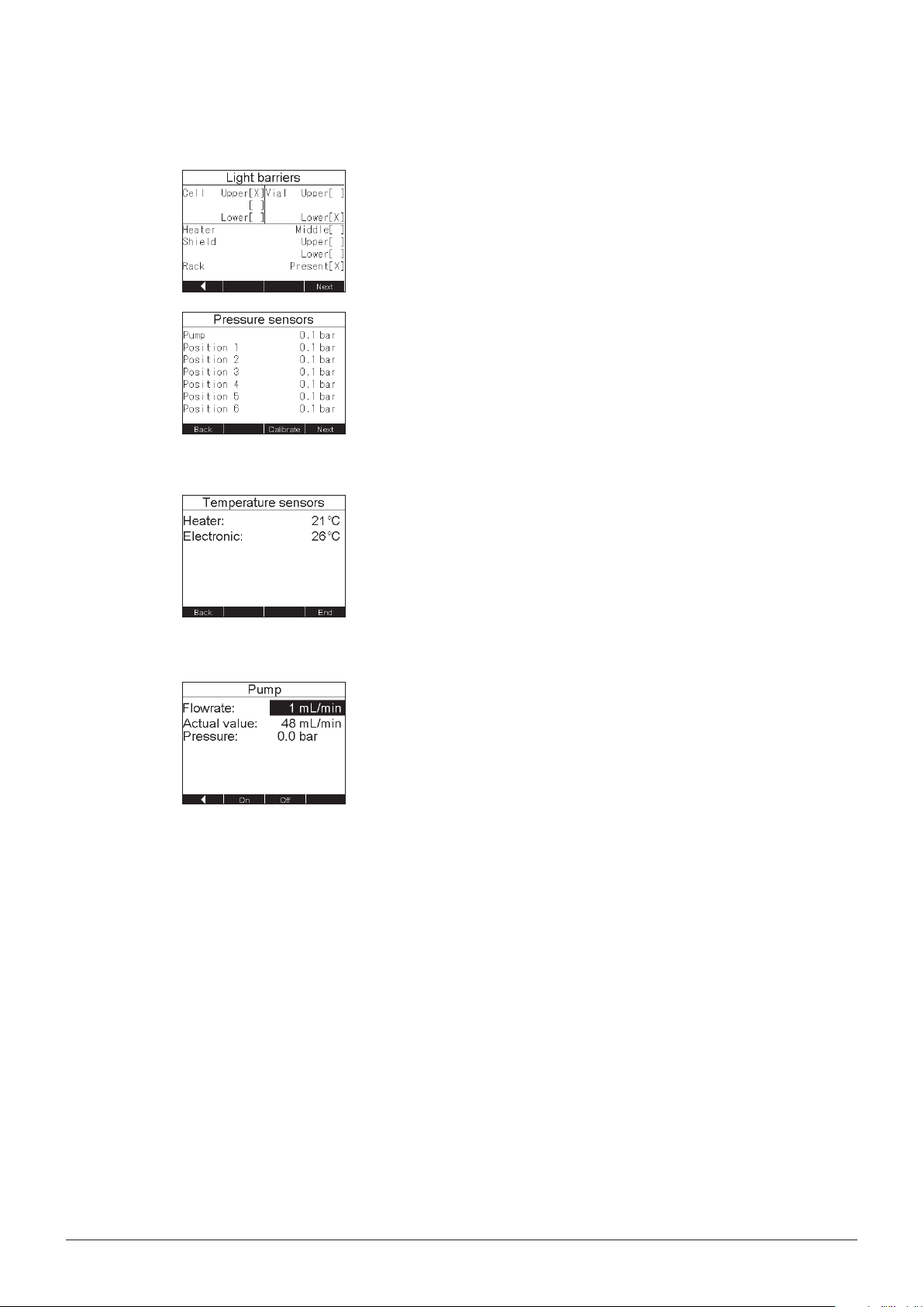
8.2.2 Checking the sensors
8 Troubleshooting
Go to SERVICE FUNCTIONS SENSORS. The position of
the lift for the heating block (CELL), the lift for the collection
rack (VIAL), the heating block (HEATER), the protection shield
(SHIELD), and the presence of the collection rack (RACK) is
shown. Crossed brackets [X] indicate the present position.
Press NEXT to enter the PRESSURE SENSORS submenu.
The overall pressure between the media valve and the divider
(indicated by PUMP; see section 4.4) and depending on the
type of instrument the pressure of the six or four position valves
is shown.
Press CALIBRATE to calibrate the pressure sensors to 0bar.
Therefore the instrument must not be under pressure, so open
the heater and the positions valve before calibration.
Press NEXT to enter the TEMPERATURE SENSORS submenu.
The temperature is shown for the heating block and the main
board (PCB).
Press END to go back to the SERVICE FUNCTIONS.
8.2.3 Running the pump
Go to SERVICE FUNCTIONS PUMP. Enter the ow rate using the selection knob (1 – 50mL/min). Press ON. The ACTUAL
VALUE converges to the set value. If the ACTUAL VALUE
remains 0, the pump is defective. Contact a BUCHI service
engineer.
The actual pressure is shown.
NOTE
Never run the pump dry. Never run the pump against a closed
valve. Solvent may get in the instrument when the extraction
positions are empty or the lift is not closed.
Go back to the SERVICE FUNCTIONS with the left arrow.
85 SpeedExtractor E-916 / E-914 Operation Manual
Page 87

8.2.4 Inspecting the lines (ow test)
8 Troubleshooting
Go to SERVICE FUNCTIONS FLOW. Dene the parameters
using the selection knob. Press START to start with the ow
test.
• Place empty extraction cells (no sand, no expansion element,
no plug screw) into the heating block and empty vials in the
collection rack (see section 6.4.1). Close the cell and vial
lift manually (see section 8.2.5). Use the same solvent as
used during the extraction when the blockage occurred.
Note the value after the system runs stably, i.e. typically after
30 – 60s.
• The pump runs at 50mL/min and generates a certain
back pressure. If the position is not blocked, the max.
pressure will be 8bar. If the position of the tested part of
the SpeedExtractor is blocked, the pressure will increase
and it will be necessary to release the pressure manually,
see section 8.1.3. Depending on the blocked part of the
SpeedExtractor it is necessary to perform several ow tests.
Proceed according to the following scheme to locate the
blocked part.
Test 1: Into vials with septa. If no pressure is built up, the
blockage during extraction was caused by the cell containing
the sample. If pressure builds up, a part inside the SpeedExtractor is blocked. Release the pressure manually and continue
with test2.
Test 2: Into vial without septa. If no pressure is built up, the
blockage is located between the vial and exhaust. The following
parts can be blocked: needles, tube from needle to exhaust,
or exhaust tube outside the unit. The needles or the exhaust
tube outside the SpeedExtractor can be exchanged following
the instruction in section 7.2.3. The tube from the needle to the
exhaust must be exchanged or cleaned by a service technician.
A leak test must be carried out to ensure the tightness of the
SpeedExtractor.
If pressure builds up, a part inside the SpeedExtractor is
blocked. Release the pressure manually and continue with
test3.
Test 3: Into waste. If no pressure built up, the blockage is located between outlet valve and vial. The following parts can be
blocked: outlet valve, capillaries, needles. The needles can be
exchanged by the operator (see section 7.2.3). The outlet valve
and the capillaries must be exchanged or cleaned by a service
technician. A leak test must be carried out to ensure the tightness of the SpeedExtractor.
If pressure builds up, a part inside the SpeedExtractor is
blocked. Release the pressure manually and continue with
test4.
86 SpeedExtractor E-916 / E-914 Operation Manual
Page 88

Test 4: Heater in the back position, beaker underneath. If no
pressure is built up, the blockage is located between lower seal
holder and outlet valve. The following parts can be blocked:
lower seal holder, cooling unit, capillary, outlet valve. These
parts must be exchanged or cleaned by a service technician.
A leak test must be carried out to ensure the tightness of the
SpeedExtractor.
If pressure builds up, the top cover plate or the parts up to the
solvent valve are blocked. Release the pressure manually. The
top cover plate can be exchanged or cleaned by the operator. If
parts before the top cover plate are blocked the service technician has to exchange or clean these parts.
Go back to the SERVICE FUNCTIONS with the left arrow.
Flow test Clogging caused by:
8 Troubleshooting
Tes t 1
Tes t 2
Tes t 3
Flow test into Vials with
septa
Not ok
Flow test into Vials
without septa
Not ok
Flow test into Waste
Not ok
ok
Between vial and exhaust:
ok
ok
needles, tube to exhaust,
Between outlet valve and
vial: outlet valve, capillaries,
Cell
exhaust tube outside
needle
Between lower seal holder
and outlet valve: lower seal
holder, cooling unit, capillary,
outlet valve
Tes t 4
Flow test: Heater in back
position, beaker under-
neath
Not ok
Top cover plate or before
ok
87 SpeedExtractor E-916 / E-914 Operation Manual
Page 89

8.2.5 Moving the cell and vial lift
8.2.6 Changing the fan performance
8 Troubleshooting
Go to SERVICE FUNCTIONS LIFT. The position of the lift for
the heating block (CELL) and the collection rack (VIAL) is shown
by crossed brackets [X]. Select the CELL or VIAL lift using the
selection knob and press UP or DOWN to move the lift. Press
stop to STOP movement. The changes in the position are
shown by light barriers (open [ ] or crossed [X] brackets). The
current entry is an indication of possible blockage of the lift.
Go back to the SERVICE FUNCTIONS with the left arrow.
Go to SERVICE FUNCTIONS FAN. The performance of the
internal fan is set to 30% for normal operation. In case of a
fault event the performance is set to 100% to get rid of any
solvent possibly leaking from the system.
NOTE
It is not advisable to change this setting as it has an impact on
the actual temperature of the heating block.
8.2.7 Displaying the operating hours
8.2.8 Unit information
Go back to the SERVICE FUNCTIONS with the left arrow.
Go to SERVICE FUNCTIONS OPERATING HOURS. The
number of extractions and leak tests as well as the operating
hours of the instrument and the heater are listed. Further information like highest achieved temperature or pressure is also
shown. This information is particularly important for the service
technician. Go back to the SERVICE FUNCTIONS with the left
arrow.
Go to SERVICE FUNCTIONS UNIT INFORMATION. The unit
information submenu contains specications of the instrument
and certain components such as serial number (SN) and rmware version (FW) which are helpful in case of troubleshooting.
Go back to the SERVICE FUNCTIONS with the left arrow.
88 SpeedExtractor E-916 / E-914 Operation Manual
Page 90

8.3 Customer service
Only authorized service personnel are allowed to perform repair work on the instrument. These persons have comprehensive technical training and knowledge of the possible dangers that can arise
from the instrument.
Contacts for ocial BUCHI customer service oces are provided on the BUCHI website
at: www.buchi.com. If your instrument malfunctions or you have technical questions or application
problems, please contact one of these oces.
Customer service oers the following:
• Spare part delivery
• Repairs
• Technical advice
8 Troubleshooting
89 SpeedExtractor E-916 / E-914 Operation Manual
Page 91

8 Troubleshooting
90 SpeedExtractor E-916 / E-914 Operation Manual
Page 92

9 Shutdown, storage, transport and disposal
This chapter instructs how to shut down and to pack the instrument for storage or transport. Specications for storage and shipping conditions can also be found listed here.
9.1 Storage and transport
Switch o the instrument and remove the power cord. To disassemble the SpeedExtractor follow the
installation instructions in section 5 in reverse order. Remove all liquids and dusty and hazardous residues before packaging the instrument.
!
WARNING
Death or serious poisoning by contact or incorporation of harmful substances.
• Wear safety goggles
• Wear safety gloves
• Wear a laboratory coat
• Flush the instrument and clean all accessories thoroughly to remove possibly dangerous
substances
• Do not clean dusty parts with compressed air
• Store the instrument and its accessories at a dry place in its original packaging
9 Shutdown, storage, transport and disposal
CAUTION
!
Risk of minor or moderate injury by heavy weight of the instrument.
• Consult three further persons to transport the instrument
• Do not drop the instrument or its transport box
• Place the instrument on a stable, even and vibration-free surface
• Keep limbs out of crushing zone
91 SpeedExtractor E-916 / E-914 Operation Manual
Page 93

9.2 Disposal
For instrument disposal in an environmentally friendly manner, a list of materials is given in chapter 3.3.
This helps to ensure that the components can be separated and recycled correctly by a specialist for
disposal.
For disposal of liquids and consumables such as catalyst or acid, see data sheets of these chemicals.
Follow valid regional and local laws concerning disposal. For help, please contact the local authorities.
NOTE
When returning the instrument to the manufacturer for repair work, please copy and complete the
health and safety clearance form on the following page and enclose it with the instrument.
9 Shutdown, storage, transport and disposal
92 SpeedExtractor E-916 / E-914 Operation Manual
Page 94
9.3 Health and safety clearance
Health and Safety Clearance
Declaration concerning safety, potential hazards and safe disposal of waste.
For the safety and health of our staff, laws and regulations regarding the handling of
dangerous goods, occupational health and safety regulations, safety at work laws and
regulations regarding safe disposal of waste, e.g. chemical waste, chemical residue or
solvent, require that this form must be duly completed and signed when equipment or
defective parts were delivered to our premises.
Instruments or parts will not be accepted if this declaration is not present.
Equipment
Model: Part/Instrument no.:
1.A Declaration for non dangerous goods
We assure that the returned equipment
has not been used in the laboratory and is new
was not in contact with toxic, corrosive, biologically active, explosive, radioactive or
other dangerous matters.
is free of contamination. The solvents or residues of pumped media have been
drained.
1.B Declaration for dangerous goods
List of dangerous substances in contact with the equipment:
Chemical, substance Danger classification
We assure for the returned equipment that
all substances, toxic, corrosive, biologically active, explosive, radioactive or
dangerous in any way which have pumped or been in contact with the equipment
are listed above.
the equipment has been cleaned, decontaminated, sterilized inside and outside and
all inlet and outlet ports of the equipment have been sealed.
2. Final Declaration
We hereby declare that
- we know all about the substances which have been in contact with the equipment
and all questions have been answered correctly
- we have taken all measures to prevent any potential risks with the delivered
equipment.
9 Shutdown, storage, transport and disposal
Company name or stamp:
Place, date:
Name (print), job title (print):
Signature:
93 SpeedExtractor E-916 / E-914 Operation Manual
Page 95

9 Shutdown, storage, transport and disposal
94 SpeedExtractor E-916 / E-914 Operation Manual
Page 96

10 Spare parts
This chapter lists spare parts and optional extras, including all of the relevant order information for
ordering from BUCHI. Always indicate the product designation and part number when ordering any
spare parts. Use only genuine BUCHI consumables and spare parts for maintenance and repair, in
order to ensure optimum system performance and reliability. Prior written permission of the manufacturer should be obtained before any modications are made to the spare parts used.
a
b
c
d
e
f
10 Spare parts
Accessories related to the extraction cell
Item Order no
a Extraction cell E-916, 10mL 051237
Extraction cell E-916, 20mL 051236
Extraction cell E-916, 40mL 051235
Extraction cell E-914, 10mL* 110 679 8 8
Extraction cell E-914, 20mL* 110 679 8 9
Extraction cell E-914, 40mL 051234
Extraction cell E-914, 80mL 051233
Extraction cell E-914, 120mL 051232
b Expansion element, 2mL 053708
Expansion element, 10mL 053359
Expansion element, 20mL 053358
Expansion element, 40mL 053357
Expansion element, 80mL 053356
Expansion element, 120mL 053355
c Funnel E-916, 10mL 053035
Funnel E-916, 20mL 053396
Funnel E-916, 40mL 053397
Funnel E-914, 10 - 20 mL 110 67 712
Funnel E -914, 40 – 120mL 053036
d Plunger E-916 053037
Plunger E-914 053038
e Extraction cell gripper E-916 053030
Extraction cell gripper E-914 053026
f Extraction cell rack E-916 053690
Extraction cell rack E-914 053691
Extruder rod 1105528 4
*Only Firmware Version 1.05 or higher
95 SpeedExtractor E-916 / E-914 Operation Manual
Page 97

10 Spare parts
Accessories related to the standard collection unit
Item PU Order no.
a
Caps and septa for wide-ne cked
12 110 5652 8
vial, GL45 thread
b
Septa for wide-necked vials 12 053677
c
Analyst vessel, 1.0mL appendix ,
12 110 56 498
GL45 thread
c
Analyst vessel, 1.0mL appendix ,
12 11056910
GL45 thread, amber glass
d
Analyst vessel, 0.3mL appendix ,
12 110 56 499
GL45 thread
d
Analyst vessel, 0.3mL appendix ,
12 110 56911
GL45 thread, amber glass
e
PP plugs OD 43mm 100 11055713
f
Analyst vessel, 1.0mL appe ndix 12 046015
g
Analyst vessel, 0.3mL appendix 12 046016
h
Retaining plate for Syncore
1 11057054
Analyst vessels for E-916
p
Polyvap vessel wide necked 12 040907
i
Caps and septa for narrow-
100 1105 6535
necked vials
j
Septa for narrow-necked vials 100 049536
k
Collection vials, 60mL 72 049535
l
Retaining plate E-914 for 60mL
2 11055205
vials
Retaining plate E-914 for 60 mL
2 110 5 9 3 65
vials
a
Caps and septa for wide-ne cked
12 110 5652 8
vial, GL45 thread
b
Septa for wide-necked vials 12 053677
m
Collection vials, wide-necked
6 053208
(GL45), round bottom, 220mL
i
Caps and septa for narrow-
100 1105 6535
necked vials
j
Septa for narrow-necked vials 100 049536
n
Collection vials , narrow- ne cked,
6 052672
at bottom, 240mL
o
Collection unit for E-916 1 053698
q
Retaining plate for Syncore
1 11058339
Analyst R-12 vessels, for E-914
r
Collection unit E-914 1 11058332
96 SpeedExtractor E-916 / E-914 Operation Manual
Page 98

b
a
10 Spare parts
Accessories related to the flask collection unit
(only for E-914)
Item PU Order no.
a
Conversion kit for the ask
1 110 5 6130
collection unit
b
Flask collection unit 1 110 56 0 43
c
500mL round bottom ask
1 000434
with 29.2/32 ange
d
250mL round bottom ask
1 000433
with 29.2/32 ange
c
d
Accessories related to the SpeedExtractor E-914,
mounted on the pedestal
Item PU Order no.
a
Flask collection unit for longer
1 11058527
asks, e.g. pear asks
b
Polyvap R-6 collection unit 1 1105852 8
97 SpeedExtractor E-916 / E-914 Operation Manual
Page 99

10 Spare parts
Accessories related to the Syncore® Analyst R-6
collection unit (only for E-914)
Item PU Order no.
a
Conversion kit for R-6 collection unit 1 11058211
b
Analyst R-6 collection unit 1 110583 44
c
R-6 vessel, 1.0mL appendix 6 038569
d
R-6 vessel, 0.3mL appendix 6 038485
e
Cover for R-6 vessels, PTFE 4 110 5 86 55
f
Septa for cover for R-6 vessels,
100 1105 8 65 6
PTFE
c
a
b
Accessories related to waste/solvent bottles
Item PU Order no.
a
Safety cap for waste bot tle, 7-port 1 1105 6 94 8
b
Safety cap, 2-port 1 110569 49
c
Solvent bottle with GL45 cap 1 053203
98 SpeedExtractor E-916 / E-914 Operation Manual
Page 100

c
a/A
d
f/6
g/G
i
10 Spare parts
Accessories related to the extraction cell
Item PU Order no.
a
Top cup seals for E-916, PTFE 12 053669
A
Top cup seals for E-916, PE* 12 11056106
a
Top cup seals for E-914, PTFE 12 053671
A
Top cup seals for E-914, PE* 12 11056108
b
Bottom cup seals, PTFE 12 053670
B
Bottom cup seals, PE* 12 1156107
c
Supporting ring, PEEK for E-916 2 053666
c
Supporting ring, PEEK for E-914 2 053667
d
Top cover plates for E-916 2 053672
d
Top cover plates for E-914 2 053673
e
Bottom cover plates for E-916/E-
2 053674
914
h
e
B/b
f
Top lter for E-916, cellulose 100 049572
f
Top lter for E-914, cellulose 100 051249
6
Top lter for E-916, glass ber 100 1105718 9
6
Top lter for E-914, glass ber 100 11057190
g
Bottom lter for E-916 / E-914,
100 049569
cellulose
G
Bottom lter for E-916 / E-914,
100 11055932
glass ber
h
Metal frit 25 049568
i
Plug screw 2 053209
* The instrument is equipped with PTFE seals by default. The
correspondi ng PE seals a re opti onall y availa ble as a ccessor y (ma x.
temperature 100°C).
Disposables
Item PU Order no.
Extr ac tio n thimbl e, cellulose, 40mL 25 110 5533 4
Extra c tion thimb le, cellulos e, 80mL 25 11059610
Extraction thimble, cellulose,
25 110 5 5 3 5 8
120mL
Extraction thimble, glass ber,
25 110 566 3 3
40mL
Extraction thimble, glass ber,
25 110 5 9 612
80mL
Extraction thimble, glass ber,
25 110 5 9 611
120mL
99 SpeedExtractor E-916 / E-914 Operation Manual
 Loading...