

Page 1

SpeedDigester K-439
Operation Manual
11593351 en
Page 2

Imprint
Product Identification:
Operation Manual (Original), SpeedDigester K-439
11593351B en
Publication date:
10.2019, Version B
BÜCHI Labortechnik AG
Meierseggstrasse 40
Postfach
CH-9230 Flawil 1
E-Mail: quality@buchi.com
BUCHI reserves the right to make changes to the manual as deemed necessary in the light of experience; especially in respect to structure, illustrations and technical detail.
This manual is copyright. Information from it may not be reproduced, distributed, or used for competitive purposes, nor made available to third parties. The manufacture of any component with the aid of this
manual without prior written agreement is also prohibited.
Page 3

Table of contents
Table of contents
1 About this manual . . . . . . . . . . . . . . . . . . . . . . . . . . . . . . . . . . . . . . .5
2 Safety. . . . . . . . . . . . . . . . . . . . . . . . . . . . . . . . . . . . . . . . . . . . . .6
2.1 User qualification . . . . . . . . . . . . . . . . . . . . . . . . . . . . . . . . . . . . 6
2.2 Proper use . . . . . . . . . . . . . . . . . . . . . . . . . . . . . . . . . . . . . . . 6
2.3 Improper use . . . . . . . . . . . . . . . . . . . . . . . . . . . . . . . . . . . . . . 6
2.4 Safety warnings and safety signs used in this manual . . . . . . . . . . . . . . . . . . 7
2.5 Product safety. . . . . . . . . . . . . . . . . . . . . . . . . . . . . . . . . . . . . .9
2.5.1 General hazards. . . . . . . . . . . . . . . . . . . . . . . . . . . . . . . . . . . . .9
2.5.2 Warning labels on housing and assemblies . . . . . . . . . . . . . . . . . . . . . . 11
2.5.3 Personal protective equipment . . . . . . . . . . . . . . . . . . . . . . . . . . . . 11
2.5.4 Built-in safety elements and measures . . . . . . . . . . . . . . . . . . . . . . . . 12
2.6 General safety rules . . . . . . . . . . . . . . . . . . . . . . . . . . . . . . . . . . 12
3 Technical data . . . . . . . . . . . . . . . . . . . . . . . . . . . . . . . . . . . . . . . . 13
3.1 Scope of application and delivery . . . . . . . . . . . . . . . . . . . . . . . . . . . 13
3.1.1 Available system configurations . . . . . . . . . . . . . . . . . . . . . . . . . . . . 13
3.1.2 Accessories for 300 ml sample tubes (for standard applications) . . . . . . . . . . . 14
3.1.3 Accessories for 500 ml sample tubes (for large sample volumes / at low nitrogen level) 14
3.1.4 Accessories for 3rd party production, 250 ml sample tubes . . . . . . . . . . . . . . 15
3.2 Technical data . . . . . . . . . . . . . . . . . . . . . . . . . . . . . . . . . . . . . 16
3.3 Materials used. . . . . . . . . . . . . . . . . . . . . . . . . . . . . . . . . . . . . 17
4 Description of function . . . . . . . . . . . . . . . . . . . . . . . . . . . . . . . . . . . 18
4.1 Functional principle . . . . . . . . . . . . . . . . . . . . . . . . . . . . . . . . . . 18
5 Putting into operation . . . . . . . . . . . . . . . . . . . . . . . . . . . . . . . . . . . . 19
5.1 Installation site. . . . . . . . . . . . . . . . . . . . . . . . . . . . . . . . . . . . . 19
5.2 System fixation . . . . . . . . . . . . . . . . . . . . . . . . . . . . . . . . . . . . 20
5.3 Electrical connections . . . . . . . . . . . . . . . . . . . . . . . . . . . . . . . . . 21
5.3.1 SpeedDigester connection . . . . . . . . . . . . . . . . . . . . . . . . . . . . . . 21
5.3.2 Scrubber/water jet pump connection . . . . . . . . . . . . . . . . . . . . . . . . . 21
6 Operation . . . . . . . . . . . . . . . . . . . . . . . . . . . . . . . . . . . . . . . . . . 22
6.1 Operating controls and housing . . . . . . . . . . . . . . . . . . . . . . . . . . . . 22
6.1.1 SpeedDigester K-439 — front side . . . . . . . . . . . . . . . . . . . . . . . . . . 22
6.1.2 System rear side . . . . . . . . . . . . . . . . . . . . . . . . . . . . . . . . . . . 23
6.2 User interface . . . . . . . . . . . . . . . . . . . . . . . . . . . . . . . . . . . . . 24
6.3 Program structure overview . . . . . . . . . . . . . . . . . . . . . . . . . . . . . . 25
6.4 Software buttons . . . . . . . . . . . . . . . . . . . . . . . . . . . . . . . . . . . 26
6.5 Software icons . . . . . . . . . . . . . . . . . . . . . . . . . . . . . . . . . . . . 27
6.5.1 General icons (used in automatic and manual mode) . . . . . . . . . . . . . . . . . 27
6.5.2 Icons in automatic mode . . . . . . . . . . . . . . . . . . . . . . . . . . . . . . . 27
6.5.3 Icons in manual mode . . . . . . . . . . . . . . . . . . . . . . . . . . . . . . . . . 27
6.6 How to prepare the software for routine digestion . . . . . . . . . . . . . . . . . . . 28
6.6.1 Standard instrument settings . . . . . . . . . . . . . . . . . . . . . . . . . . . . . 28
6.6.2 Digestion in Manual Mode. . . . . . . . . . . . . . . . . . . . . . . . . . . . . . . 29
6.6.3 Methods menu . . . . . . . . . . . . . . . . . . . . . . . . . . . . . . . . . . . . 30
6.6.4 Digestion in Automatic Mode . . . . . . . . . . . . . . . . . . . . . . . . . . . . . 35
6.6.5 History menu . . . . . . . . . . . . . . . . . . . . . . . . . . . . . . . . . . . . . 36
6.7 Preparing of SpeedDigester, suction module(s) and sample tubes. . . . . . . . . . . 36
3 K-439 Operation Manual, Version B
Page 4

Table of contents
6.7.1 Kjeldahl digestion —preparing sample tubes. . . . . . . . . . . . . . . . . . . . . . 37
6.7.2 Peroxide digestion —preparing sample tubes . . . . . . . . . . . . . . . . . . . . . 38
6.7.3 Installing a suction module and sample tubes (300 ml). . . . . . . . . . . . . . . . . 39
6.7.4 Installing 500 ml sample tubes. . . . . . . . . . . . . . . . . . . . . . . . . . . . . 41
6.7.5 Starting up the SpeedDigester . . . . . . . . . . . . . . . . . . . . . . . . . . . . 43
6.8 Performing a Kjeldahl digestion process. . . . . . . . . . . . . . . . . . . . . . . . 43
6.8.1 Preparational steps . . . . . . . . . . . . . . . . . . . . . . . . . . . . . . . . . . 43
6.8.2 Starting a digestion process. . . . . . . . . . . . . . . . . . . . . . . . . . . . . . 43
6.9 Performing a peroxide digestion process . . . . . . . . . . . . . . . . . . . . . . . 44
6.9.1 Preparational steps . . . . . . . . . . . . . . . . . . . . . . . . . . . . . . . . . . 44
6.9.2 Starting a digestion process. . . . . . . . . . . . . . . . . . . . . . . . . . . . . . 44
6.10 Finishing a digestion process . . . . . . . . . . . . . . . . . . . . . . . . . . . . . 46
6.11 Optional 'Stand with drip tray' . . . . . . . . . . . . . . . . . . . . . . . . . . . . . 49
7 Maintenance and repairs . . . . . . . . . . . . . . . . . . . . . . . . . . . . . . . . . . 50
7.1 Customer service . . . . . . . . . . . . . . . . . . . . . . . . . . . . . . . . . . . 51
7.2 General condition and cleaning instructions . . . . . . . . . . . . . . . . . . . . . . 51
7.2.1 Breakage of glassware inside a housing chamber . . . . . . . . . . . . . . . . . . . 52
7.2.2 Liquid ingress into the instrument . . . . . . . . . . . . . . . . . . . . . . . . . . . 52
7.3 Glass component conditions . . . . . . . . . . . . . . . . . . . . . . . . . . . . . 53
7.3.1 Sample tubes . . . . . . . . . . . . . . . . . . . . . . . . . . . . . . . . . . . . . 53
7.4 Sealing system . . . . . . . . . . . . . . . . . . . . . . . . . . . . . . . . . . . . 53
7.5 Rack system . . . . . . . . . . . . . . . . . . . . . . . . . . . . . . . . . . . . . 54
7.5.1 300 ml sample tube support spring . . . . . . . . . . . . . . . . . . . . . . . . . . 54
7.5.2 500 ml sample tube support spring . . . . . . . . . . . . . . . . . . . . . . . . . . 55
7.6 Display cover . . . . . . . . . . . . . . . . . . . . . . . . . . . . . . . . . . . . . 55
8 Troubleshooting . . . . . . . . . . . . . . . . . . . . . . . . . . . . . . . . . . . . . . . 56
8.1 Malfunctions and their remedy. . . . . . . . . . . . . . . . . . . . . . . . . . . . . 56
8.2 Diagnostics . . . . . . . . . . . . . . . . . . . . . . . . . . . . . . . . . . . . . . 57
8.2.1 Actors . . . . . . . . . . . . . . . . . . . . . . . . . . . . . . . . . . . . . . . . . 57
8.2.2 Sensors . . . . . . . . . . . . . . . . . . . . . . . . . . . . . . . . . . . . . . . . 58
8.2.3 Operating Hours. . . . . . . . . . . . . . . . . . . . . . . . . . . . . . . . . . . . 58
8.2.4 Unit Information . . . . . . . . . . . . . . . . . . . . . . . . . . . . . . . . . . . . 58
8.2.5 Service Test . . . . . . . . . . . . . . . . . . . . . . . . . . . . . . . . . . . . . . 58
8.3 Device fuses. . . . . . . . . . . . . . . . . . . . . . . . . . . . . . . . . . . . . . 59
9 Shutdown, storage, transport and disposal . . . . . . . . . . . . . . . . . . . . . . . . 60
9.1 Storage and transport . . . . . . . . . . . . . . . . . . . . . . . . . . . . . . . . . 60
9.2 Disposal. . . . . . . . . . . . . . . . . . . . . . . . . . . . . . . . . . . . . . . . 61
10 Spare parts. . . . . . . . . . . . . . . . . . . . . . . . . . . . . . . . . . . . . . . . . . 63
10.1 Spare parts, optional accessories and consumables . . . . . . . . . . . . . . . . . 63
11 Declarations and requirements. . . . . . . . . . . . . . . . . . . . . . . . . . . . . . . 66
11.1 FCC requirements (for USA and Canada) . . . . . . . . . . . . . . . . . . . . . . . 66
4 K-439 Operation Manual, Version B
Page 5

1 About this manual
This manual describes the SpeedDigester K-439 and provides all information required for its safe
operation and to maintain it in good working order.
It is addressed to laboratory personnel and operators in particular.
Read this manual carefully before installing and running your system and note the safety precautions
in chapter 2 in particular. Store the manual in the immediate vicinity of the instrument, so that it can be
consulted at any time.
No technical modifications may be made to the instrument without the prior written agreement of
Buchi. Unauthorized modifications may affect the system safety or result in accidents. Technical data
are subject to change without notice.
NOTE
The symbols pertaining to safety (WARNINGS and ATTENTIONS) are explained in chapter 2.
1 About this manual
This manual is copyright. Information from it may not be reproduced, distributed or used for competitive purposes, nor made available to third parties. The manufacture of any component with the aid of
this manual without prior written agreement is also prohibited.
The English manual is the original language version and serves as basis for all translations into other
languages. If you need another language version of this manual, you can download available versions
at www.buchi.com.
5 K-439 Operation Manual, Version B
Page 6

2 Safety
This chapter introduces the safety concept of the instrument and contains general rules of behavior
and warnings from direct and indirect hazards concerning the use of the product.
For the users safety, all safety instructions and safety messages in the individual chapters shall
be strictly observed and followed. Therefore, the manual must always be available to all persons
performing any tasks described herein.
2.1 User qualification
The instrument may only be used by laboratory personnel and other persons who on account of
training and professional experience know the potential dangers that can develop when operating the
instrument.
Untrained personnel, or persons who are currently being trained, require careful supervision by a
qualified person. Operation Manual serves as a basis for training.
2 Safety
2.2 Proper use
The SpeedDigester K-439 has been designed and built for laboratory use only. Its intended use is to
allow digestion of samples with concentrated acids or peroxides by heating up the probe.
A suction unit (e.g. Scrubber or water jet pump) has to be connected to the suction module to safely
withdraw fumes which will emerge during digestion. In any case, all exhausts and fumes leaving the
system or assemblies such as Scrubber or water jet pump have to be removed instantly inside a
fume hood. This is mandatory to remove all possibly hazardous substances (e.g. acid fumes) from the
working area. The ventilation system of the fume hood has to be equipped with safety measures such
as outlet filters to avoid contamination of the environment.
When the SpeedDigester K-439 is used in combination with other instruments (e.g. Scrubber and
fume hood) all related manuals are to be fully observed.
2.3 Improper use
Applications not mentioned in section 2.2 are considered to be improper. Applications which do not
comply with the technical data (see section 3 of this manual) are also considered to be improper.
The operator bears the sole risk for any damages or hazards caused by improper use!
The following uses are expressly forbidden:
• Digestion operations outside an active fume hood.
• Digestion of samples (e.g. food and feed) in nitrosulfuric acids which can produce explosive nitro
compounds.
• Digestion of sample material of unknown composition in nitrosulfuric acids.
• Use of samples which can explode or ignite due to shocks, friction, heat or sparks.
• Installation or use of the instrument in rooms, which require ex-protected instruments.
• Use of glassware which is not specified in section 2.5.4.
6 K-439 Operation Manual, Version B
Page 7

2.4 Safety warnings and safety signs used in this manual
DANGER, WARNING, CAUTION and NOTICE are standardized signal words for identifying levels of
hazard seriousness of risks related to personal injury and property damage. All signal words, which are
related to personal injury are accompanied by the general safety sign.
For your safety it is important to read and fully understand the table below with the different signal
words and their definitions!
Sign Signal word Definition Risk level
DANGER
Indicates a hazardous situation which, if not avoided, will result in
death or serious injury.
2 Safety
★★★★
WARNING
CAUTION
no NOTICE
Supplementary safety information symbols may be placed in a rectangular panel on the left to the
signal word and the supplementary text (see below example).
Space for
supplementary
safety
information
symbols.
Table of supplementary safety information symbols
The reference list below incorporates all safety information symbols used in this manual and their
meaning.
Indicates a hazardous situation which, if not avoided, could result
in death or serious injury.
Indicates a hazardous situation which, if not avoided, may result
in minor or moderate injury.
Indicates possible property damage, but no
practices related to personal injury.
!
SIGNAL WORD
Supplementary text, describing the kind and level of hazard / risk seriousness.
• List of measures to avoid the herein described, hazard or hazardous situation.
• ...
• ...
(property damage only)
★★★☆
★★☆☆
★☆☆☆
Symbol Meaning
General warning
Electrical hazard
Heavy weight, avoid overexertion
7 K-439 Operation Manual, Version B
Page 8
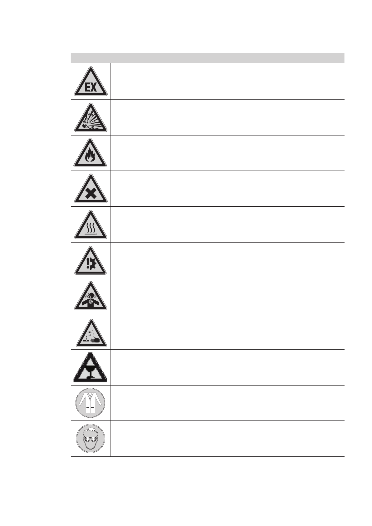
Symbol Meaning
Explosive gases, explosive environment
Explosive material
Fire hazard
Harmful to life-forms
2 Safety
Hot item, hot surface
Device damage
Inhalation of substances
Chemical burns by corrosives
Fragile components
Wear laboratory coat
Wear protective goggles
8 K-439 Operation Manual, Version B
Page 9

2 Safety
Symbol Meaning
Wear protective gloves
Heavy weight, lifting requires more than one person
Additional user information
Paragraphs starting with Note transport helpful information for working with the device / software or its
supplementaries. Notes are not related to any kind of hazard or damage (see following example).
Note
Useful tips for the easy operation of the instrument / software.
2.5 Product safety
The SpeedDigester K-439 has been designed and built in accordance with current state-of-the-art
technology. Safety warnings in this manual (as described in section 2.4) serve to make the user alert
to and avoid hazardous situations emanating from residual dangers by giving appropriate counter
measures.
However, risks to users, property and the environment can arise when the instrument is damaged,
used carelessly or improperly.
2.5.1 General hazards
The following safety messages show hazards of general kind which may occur when handling the
instrument. The user shall observe all listed counter measures in order to achieve and maintain the
lowest possible level of hazard.
Additional warning messages can be found whenever actions and situations described in this manual
are related to situational hazards.
!
DANGER
Death or serious injuries by use in explosive environments.
• Do not store or operate the instrument in explosive environments
• Do not store chemicals in the vicinity of the device
• Operate the device in a fume hood with sufcient ventilation to directly withdraw fumes
9 K-439 Operation Manual, Version B
Page 10
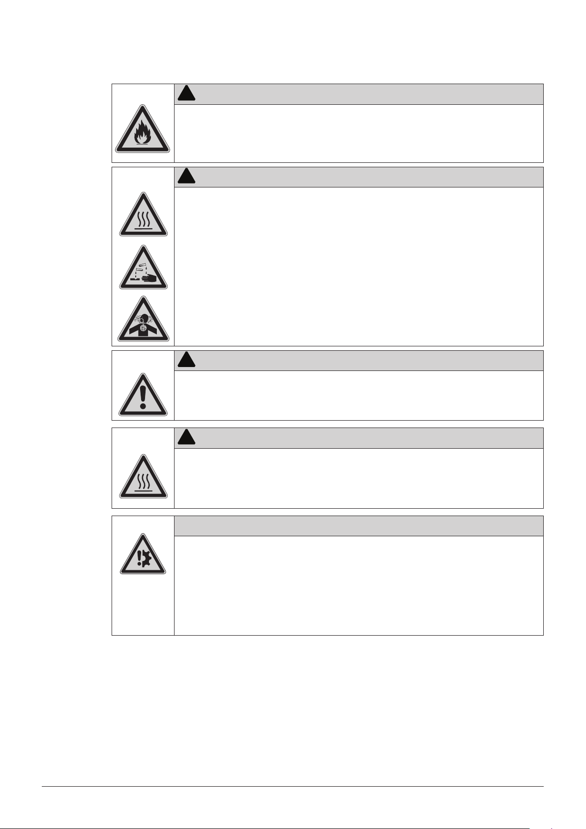
!
WARNING
Death or serious burns by ammable vapors.
• Remove all sources of ammable vapors
• Do not store ammable chemicals in the vicinity of the device
!
WARNING
Risk of death or serious chemical burns by hot acid or peroxide fumes.
• Do not operate the system with faulty parts
• Check instrument setup for proper sealing before use
• Do not inhale process fumes
• Operate the instrument inside an active fume hood
• Do not move the instrument or parts of it during digestion
2 Safety
!
CAUTION
Risk of minor or moderate cuts by sharp edges.
• Do not touch defective or broken glassware with bare hands
• Do not touch thin metal edges
!
CAUTION
Risk of burns by hot machine parts and glassware.
• Do not touch hot parts or surfaces
• Let the system and inserted glassware cool down safely
• Do not move the instrument or parts of it when hot
Risk of instrument damage by liquids or mechanical shocks.
• Do not spill liquids over the instrument or its components
• Do not move the instrument when it is loaded with sample liquid
• Do not drop the instrument or its components
• Keep external vibrations away from the instrument
• Safely attach the instrument to the bench in earthquake prone regions
• Do not operate the instrument without the display cover installed
NOTICE
10 K-439 Operation Manual, Version B
Page 11

2.5.2 Warning labels on housing and assemblies
The following warning sticker(s) can be found on the housing or assemblies of the SpeedDigester:
Symbol Meaning Location
2 Safety
Hot item, hot surface
Do NOT put rack into side cooling position Label on 500 ml racks
2.5.3 Personal protective equipment
Always wear personal protective equipment such as protective eye goggles, protective clothing and
gloves. The personal protective equipment must meet all requirements of the supplementary data
sheets for the chemicals used.
!
WARNING
Serious chemical burns by corrosives.
• Observe supplementary data sheets of all used chemicals.
• Handle corrosives in well ventilated environments only.
• Always wear protective goggles.
• Always wear protective gloves.
• Always wear protective clothes.
• Do not use damaged glassware.
Sticker / label, located on top of the housing and
at the racks
11 K-439 Operation Manual, Version B
Page 12

2.5.4 Built-in safety elements and measures
Buchi glassware design
• All original Buchi digestion glassparts are made of high temperature and chemical resistant borosilicate glass.
• Acid fumes generated during digestion accumulate in the suction module
• The fumes must be safely withdrawn from the suction module via one or more hoses to a Scrubber
(e.g. Scrubber B-414) or via water jet pump into a sink or sufficient suction flow.
3rd party glassware
The quality of the material is an essential part of the safety concept of the SpeedDigester K-439. For
the special rack (order no. 11055440), the following qualified vendors offer sample tubes of sufficient
quality grade to withstand the temperatures and the aggressive chemical digestion agents:
Qualified vendor Tested sample tube(s)
Gerhardt 250 ml / 6100
Velp ø 42×300 mm / A00000144
Foss 250 ml / 10014278
2 Safety
Heater
Each heating chamber is equipped with a safety overtemperature switch. In case of an emergency the
switch cuts off the power of the corresponding chamber.
2.6 General safety rules
Responsibility of the operator
The head of the laboratory is responsible for training his/her personnel.
The operator shall inform the manufacturer without delay of any safety-related incidents which might
occur during operation of the instrument or its accessories. Legal regulations, such as local, state and
federal laws applying to the instrument or its accessories must be strictly followed.
Duty of maintenance and care
The operator is responsible for the proper condition of instrument. This includes maintenance, service
and repair jobs that are performed on schedule by authorized personnel only.
Spare parts to be used
Use only genuine consumables and spare parts for maintenance to assure good system performance,
reliability and safety. Any modifications of spare parts or assemblies are only allowed with the prior
written permission of the manufacturer.
Modifications
Modifications to the instrument are only permitted after prior consultation and with the written approval
of the manufacturer. Modifications and upgrades shall only be carried out by an authorized Buchi technical engineer. The manufacturer will decline any claim resulting from unauthorized modifications.
12 K-439 Operation Manual, Version B
Page 13
3 Technical data
This chapter introduces the reader to the SpeedDigester K-439 and its specifications. It contains the
scope of delivery, technical data, requirements and performance data.
3.1 Scope of application and delivery
All system configurations come with a limited set of accessories as a starter kit. Within a system family,
additionally available accessories (see section 3.1.2 and the following) can be used to easily reconfigure your system to every configuration listed in section 3.1.1.
Parts that are required to change a system configuration:
• Rack
• Suction module
• Insulation plate (fireclay insert)
• Sample tubes
3 Technical data
The scope of delivery depends on the ordered system configuration and can be checked according to
the individual delivery note and the listed order numbers.
Note
For additional information about the listed products, see www.buchi.com or contact your local dealer.
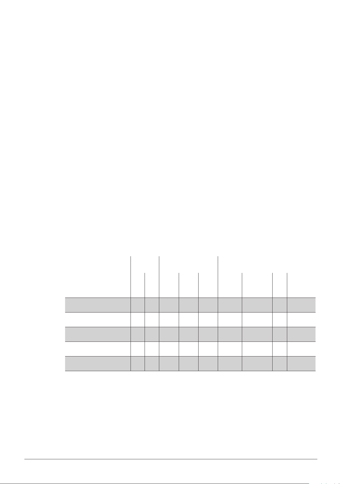
3.1.1 Available system configurations
Configuration
order number
220 – 240 V 5 6 250 ml 300 ml 500 ml Standard
1154392500
1154392100
1154392200
1154392300
1154392400
Sample
positions
Sample tube sizes Suction modules
Condensate
trap
• • •
• • •
• • •
• • •
• •* •*
H2O
Module for
3rd party
2
tubes
* Third party sample tubes require special accessories such as the BUCHI “Module for 3rd party
tubes” and the matching rack / insulation plate. Tubes are not included in the set!
13 K-439 Operation Manual, Version B
Page 14
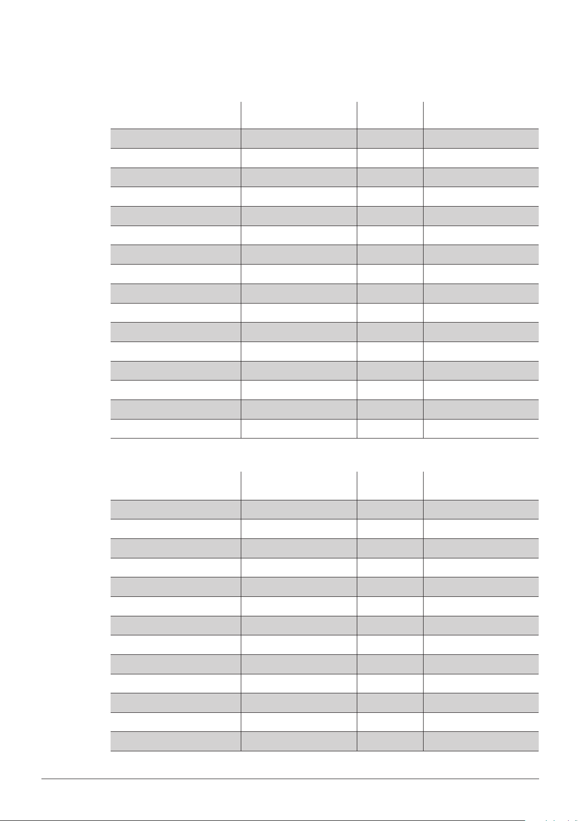
3.1.2 Accessories for 300 ml sample tubes (for standard applications)
3 Technical data
Item Additional info Order number
Recommended quantity to
order
Set of sample tubes 300 ml, 4 tubes 037377 3x
Suction module standard 6 place 11055849 2x
Suction module condensate trap 6 place 11055865 2x
Suction module H2O
2
6 place, cpl. 11055853 2x
Connectors to suction module Adapter and plug 11055367 2x
EPDM hose set Hoses and t-piece 11056219 1x
Insulation plate (reclay) Insertion, for 300 ml tubes 11055142 2x
Rack 6 place, for 300 ml tubes 11055248 2x
Glass caps (set of 4) OPTIONAL 040049 —
Insulation cap OPTIONAL 11056024 —
Sealing FKM (set of 6) Spare part 038122 —
Sealing PTFE (1 pcs) OPTIONAL 022442 —
Rubber GUKOs for H2O2 suc. mod. Spare part set of 6 044495 —
Filter funnel for H2O2 suc. mod. Spare part set of 6 044494
Set circular spring and holder Spare part set of 6 11055984 —
Bed-plate for 300ml racks OPTIONAL 11055943 —
3.1.3 Accessories for 500 ml sample tubes (for large sample volumes / at low nitrogen level)
Standard items Additional info Order number
Recommended quantity
to order
Sample tubes 500 ml, single tube 026128 10x
Set of sample tubes 500 ml, 4 tubes 043982 3x
Suction module condensate trap 5 place 11055851 2x
Connectors to suction module Adapter and plug 11055367 2x
EPDM hose set Hoses and t-piece 11056219 1x
Insulation plate (reclay) Insertion, for 500 ml tubes 11055143 2x
Rack 5 place, for 500 ml tubes 11055327 2x
Base for rack For 500 ml tubes rack 11055612 1x
Glass caps (set of 4) OPTIONAL 040049 —
Insulation cap OPTIONAL 11056024 —
Sealing FKM (set of 6) Spare part 038122 —
Sealing PTFE (1 pcs) OPTIONAL 022442 —
Interlock spring for 500 ml rack Spare part 11055385 —
14 K-439 Operation Manual, Version B
Page 15

3.1.4 Accessories for 3rd party production, 250 ml sample tubes
3 Technical data
Item Additional info Order number
3rd party sample tubes 250 ml n.a. 12x
Suction module for 3rd party tubes 6 place 11055850 2x
Connectors to suction module Adapter and plug 11055367 2x
EPDM hose set Hoses and t-piece 11056219 1x
Insulation plate (reclay) Insertion, for 250 ml tubes 11055877 2x
Rack 6 place, for 250 ml tubes 11055440 2x
Sealing FKM (set of 6) Spare part 038125 —
Set circular spring and holder 6× OPTIONAL 11055985 —
Note
Tested 3rd party sample tubes (listed in section 2.5.4) are not available at Buchi. Please contact your
local OEM vendor for these type of tubes.
Recommended quantity
to order
15 K-439 Operation Manual, Version B
Page 16

3.2 Technical data
The table below lists all main design parameters of the SpeedDigester K-439.
Technical data
Power consumption max. 2000 W
Temperature control range 50 – 580°C
Temperature accuracy ± 5 K at 200 °C / ± 10 K at 550 °C
Connection voltage 220 – 240 VAC
Frequency 50 / 60 Hz
Input fuse T 10A L 250 V
Scrubber output max. 0,7 A
Display QVGA 240×320 pixels
IP degree of protection (two digits) IP 20
3 Technical data
Explanation of protection level:
2 Protection provided by the enclosure against access
to hazardous parts (e.g., electrical conductors,
moving parts) and the ingress of solid foreign objects
with a diameter of > 12,5 mm.
0 No protection of the equipment inside the enclosure
against harmful ingress of water.
Insulation category II
Environmental conditions:
Pollution degree 2 (for indoor use only)
Temperature 5 – 40°C
Altitude (above sea level) up to 2000 m
Humidity (curve parameter) Maximum relative humidity 80% up to 31°C, then
decreasing linearly to 50% relative humidity at 40°C
Dimensions in mm (W × D × H) 310 × 620 × 540
Net weight 15,5 kg
Rack 2,5 kg (per rack)
Note
The SpeedDigester K-439 is suited to work with an input power range of 220 V to 240 V mains
voltage. Check your local voltage requirements prior to installation!
16 K-439 Operation Manual, Version B
Page 17

3.3 Materials used
Materials used
Component Material designation Material code
Stainless steel Housing
Silicic acid Heating chamber SiO2, SiC
Ceramic ber felt Heating chamber
Calcium silicate Insulation plate
Phlogopite mica Preheat cover
Plastic Front hood PBT
Borosilicate glass 3.3 Protective glass display
Aluminium Front bottom
3 Technical data
Heating chamber
Heating element
Rack
Hose clamp
Front panel under keypad PP
Display cover PVC
Suction hoses EPDM
Drip tray PP
Rack PPS
Sealings suction tube FKM/PFE
Hose coupling PP
Digestion tubes
Suction tube
Heat sink front
17 K-439 Operation Manual, Version B
Page 18

4 Description of function
This chapter explains the basic working principle of the SpeedDigester K-439. It also shows how the
instrument is structured and provides a general functional description of its assemblies.
4.1 Functional principle
The SpeedDigester K-439 is a special heating device to digest samples. It can generate max. temperatures of 580 °C. This allows e.g. acid digestion of organic sample components in a concentrated
sulfuric acid / catalyst mixture, known as 'Kjeldahl digestion'. During the processing the sample
material can reach peak temperatures of up to 370 °C at the bottom area of the sample tubes. The
maximum temperature of the sample highly depends on its composition i.e. the ratio of catalyst to
acid and can change during the digestion process.
Digestion process overview
Environmental
air inlet
dangerous vapors are drawn away
4 Description of function
Acid vapor
outlet to
suction unit
(e.g. Scrubber)
4
2
Safety
zone
Insulation plate
(reclay insertion)
3
Infrared heating
(≈ 5 cm)
Condensation
zone
Boiling / digesting
sample
1
Processing steps:
• The infrared heating 1 generates high temperatures in the sample.
• Inside the sample tubes the digestion process takes place 2 while the acid is constantly boiling.
• Hot acid fumes rise into the condensing zone 3. After reflux, the acid flows back down to the
sample material, establishing a constant cycle.
• Residual fumes which escapes the condensation zone is highly corrosive (!) and hazardous to life
forms. It must be withdrawn by a suction unit that deliveres sufficient flow (i.e. with a Scrubber
B-414 or a water jet pump) 4.
Note
The condensation should not take place inside the safety zone in order to prevent digestion of the
sealing rings. In case the condensation is too close to the suction module (e.g. due to very high
temperature settings) the digestion fumes may escape and the sample can dry out!
18 K-439 Operation Manual, Version B
Page 19

5 Putting into operation
This chapter describes how the instrument has to be installed. It also gives instructions for the initial
startup.
Note
Inspect the instrument for damage during unpacking. If necessary, prepare a status report immediately to inform your Buchi representative. In some countries it is necessary to additionally inform the
postal company, railway company or transportation company. Keep the original packaging for future
transportation.
5.1 Installation site
Put the instrument into a fume hood onto a clean, stable and horizontal surface. Consider the
maximum product dimensions and weight. Obtain the environmental conditions as described in
section 3.2, technical data.
5 Putting into operation
Installation prerequisites and installation steps:
• The fume hood must be equipped with a heat- and acid-resistant lining.
• Do not place any objects on top or below the instrument.
• The instrument must be installed with a safety clearance of not less than 5 cm to any other
objects or walls to allow sufficient cooling.
• Do not place containers, chemicals or other items behind the instrument.
• When using a Scrubber B-414 it must be placed on the left side of the SpeedDigester.
Note
• T o cut the power in case of an emergency by unplugging, the instruments or any other items
must not block the mains plug!
• Any cooling of the SpeedDigester can disturb the digestion process. When switched 'On', the
Scrubber B-414 cooling fan emits from the left side of the housing. Hence the Scrubber B-414
should not be installed on the right side of the SpeedDigester.
!
DANGER
Death or serious injuries by use in explosive environments.
• Do not store or operate the instrument in explosive environments
• Do not store chemicals in the vicinity of the device
• Operate the device in a fume hood with sufcient ventilation to directly withdraw fumes
19 K-439 Operation Manual, Version B
Page 20

WARNING
!
Risk of death or burns by electric current.
• Check for proper grounding before use
• Exchange defective cabling instantly
CAUTION
!
Risk of minor or moderate injury by heavy weight of the instrument.
• Lift the instrument carefully and avoid over exertion
• Do not drop the instrument or its transport box
• Place the instrument on a stable, even and vibration-free surface
• Keep limbs out of crushing zone
5 Putting into operation
5.2 System fixation
In earthquake prone regions the instrument must be fixed to the fume hood bench. The penetration
depth of the stainless steel fixation screw must not be more than 10 mm.
System xation point
(insert nut)
Risk of instrument damage by earthquakes
• Safely attach the instrument to the bench in earthquake prone regions
• Use acid resistant stainless steel screws
Notice
2×
M4×10
20 K-439 Operation Manual, Version B
Page 21

5.3 Electrical connections
5.3.1 SpeedDigester connection
After the installation procedure has been completed successfully, the power plug of the SpeedDigester
must be connected to the mains for the digestion process.
5 Putting into operation
Risk of instrument damage by wrong mains supply.
• External mains supply must meet the voltage given on the type plate
• Check for proper grounding
The used mains circuit has to:
• provide the voltage that is given on the type plate of the instrument.
• be able to handle the load of the connected instruments.
• be equipped with adequat fusage and electrical safety measures, in particular proper earthing.
See also technical data of all components regarding the different minimum system requirements!
Note
Additional electrical safety measures such as residual current breakers may be necessary to meet
local laws and regulations! External connections and extension lines must be provided with an
earthed conductor lead (3-pole couplings, cord or plug equipment). All used power cords shall be
equipped with moulded plugs only to avoid risks due to unobservant defective wiring.
5.3.2 Scrubber/water jet pump connection
To start the Scrubber B-414 automatically when the digestion process starts, directly connect it to the
SpeedDigester K-439 with the optional connection cable (Art. No. 14738).
Make sure that the voltage of the Scrubber B-414 corresponds to the voltage of the K-439.
Notice
1
2
Mains socket for
Scrubber connection
To connect a Scrubber/water jet pump the plastic adapter piece must be installed to the suction
module and the hose connector must be mounted at the EPDM hose of the suction module 1 (see
section 6.7.3).
Now connect the EPDM hose coming from the T-piece 2 to the Scrubber B-414 or the water jet
pump to exhaust the digestion fumes (for a more detailed description see the corresponding instruction manuals of these devices). Make sure that the hose connection is as short as possible.
21 K-439 Operation Manual, Version B
Page 22

6 Operation
This chapter gives examples of typical instrument applications and instructions on how to operate the
instrument properly and safely. See also section 2.5 “Product safety” for general warnings.
6.1 Operating controls and housing
The SpeedDigester K-439 is equipped with electronic temperature control, an integrated LC-display
and a membrane keypad with multifunctional keys.
Up to 50 methods can be programmed, 20 of which are already predefined by default.
A method consists of Preheat step, 4 possible temperature steps and cooling-down time.
The programmed method is visualized graphically and during the digestion process the actual temperature and the set temperature as well as the remaining time are displayed. The current status during
digestion is visualized by the icons at any time.
6 Operation
6.1.1 SpeedDigester K-439 — front side
Heating chambers
LC- display
Membrane keypad
USB interface
Mains switch
• The mains switch is illuminated green when the system is switched on
• USB interface — for service purposes only
• Membrane keypad — covered by anti-corrosion foil
• Graphical LC- display
• Two heating chambers
22 K-439 Operation Manual, Version B
Page 23

6.1.2 System rear side
6 Operation
Bracket with magnetic
(elbow) suction plugs
T-piece with
suction hoses
Type plate
Mains socket for
Scrubber connection
Power socket
Fuse holders
Fuse type:
T 10A L 250 V
• To access the glass fuses on the rear side use a slotted screwdriver.
➥ Slightly push in the slotted insert and turn it approx. a quarter-turn counterclockwise.
➥ Release the pressure off the insert — it will pop out by weak spring force.
23 K-439 Operation Manual, Version B
Page 24

6.2 User interface
Start
6 Operation
Stop
Multipurpose buttons
Button Functionality
Start
Stop
Starts a process
Stops a process
• Increases values such as time or temperature
+
• Selects adjustments
+
–
–
• Decreases values such as time or temperature
• Selects adjustments
Functionality changes on the basis of the corresponding button description on the display
24 K-439 Operation Manual, Version B
Page 25

6.3 Program structure overview
Main menu 1st submenu 2nd submenu 3rd submenu 4th submenu
Automatic - choose one or both rows to be
active
- activate timer
- activate Preheat continue/
Preheat wait
Start the digestion method
Methods List of methods
- user methods
- Buchi methods
History View the last 3 digestion
processes
Select the required
method
- Delete Methods
- Load Methods
6 Operation
Congure and
save a method
Manual Start a manual digestion
- choose one or both rows to be
active
- start the heating
- reset time
Settings Language
Display Contrast 15 to 85
Buzzer On/Off
Scrubber present Yes/No
Device Type K-439
Demo Mode: Yes/No
Acceleration 1 to 60
Diagnostics Actors Heaters temp.
Scrubber On/Off
Backlight On/Off
Sensors Voltage, Triac, Temp.
Sensor 1 and 2
Operating hours Power-on Time,
Heating Time, Row
Left, Row Right
Unit Information Version Firmware,
Test Date Print,
Version Print, Max.
Temp. Triac/LCD
Service Test Start Service Test
(IQ/OQ)
25 K-439 Operation Manual, Version B
Page 26

6.4 Software buttons
The following control buttons are available in the software for navigation and input confirmation:
6 Operation
Next
OK
ESC
Save
Enter
Preheat
Row
Go on to the next screen, go to the next stored digestion process in the "History"
Confirm and/or save a setting and get back to the main/previous screen
Get back to the main/previous screen without saving possible settings
Back button to move backward within in the submenu structure
Forward button to move forward within in the submenu structure
Back button to move backward in the lower submenu structure
Forward button to move forward in the lower submenu structure
Move up within the entries of a screen
Move down within the entries of a screen
Save a method
Confirm the entry of a character when naming a method
.. wait: hold temp. after preheat, start step 1 of digestion by pressing START
.. continue: start step 1 of digestion automatically after preheat is done
Select left, right or both rows to be heated
Timer
+ 10 min
Set °C
Delete
Load
Edit
Cancel
Prev
Reset
Yes
No
Set required time for the delayed start time in h : min
Extend the digestion for an additional 10 minutes
Adjust the temperature during a running digestion in Automatic mode
Delete a method
Load a method
Edit a method/settings
Cancel the latest entry
Go back to the previous screen/go to the previously stored digestion in the History menu
Reset time during Manual mode
Check rows individually (OQ Service test)
Check both rows at once (OQ Service test)
Start a temperature test (OQ Service test) / affirm a question
Negate a question
26 K-439 Operation Manual, Version B
Page 27

6.5 Software icons
The software icons explained in the following are visible during a digestion process. Most of them are
displayed in the upper part of the software screen and also remain visible when leaving the digestion
screen.
Just the general icon for the selected rows and the temperature reached as well as the heating icons
in the manual mode are only visible in the digestion screen.
6.5.1 General icons (used in automatic and manual mode)
The temperature of the heating chamber is ≥ 70 °C, i.e. the heating elements are hot
Scrubber is running
6 Operation
6.5.2 Icons in automatic mode
6.5.3 Icons in manual mode
Manual mode
Selected row(s)
Data of last, last but one and last but two digestion process in History menu
Preheat function "Preheat ..wait" active. Preheating in progress.
Preheat function "Preheat ..continue" active. Preheating in progress.
Preheating finished, preheat temperature reached
Step in progress
Heating off, cool down step running
Temperature reached, i.e. actual temperature equals set temperature
Heating, i.e. set temperature higher than actual temperature
Heating off, i.e. set temperature lower than actual temperature
27 K-439 Operation Manual, Version B
Page 28

6.6 How to prepare the software for routine digestion
Configure the software according to the following steps to prepare it for routine digestion:
1. Standard instrument settings
2. Manual mode (development of digestion method)
3. Digestion methods (storage of developed method)
4. Preheating
5. Start digestion
6.6.1 Standard instrument settings
This configuration consists of typical settings, which have to be defined before the instrument is used
for the first time. These settings do not have to be changed, as long as the instrument is not updated
or extended by any additional accessory (e.g. Scrubber B-414).
Select Main Menu > Settings.
The following screen appears:
6 Operation
The following settings can be entered:
• Language (select the required language (de, en, fr, it, es, jp, zh)
• Display Contrast (15 to 85)
• Buzzer (On or Off)
• Scrubber present (Yes, if connected / No, if not connected)
• Device Type (K-439, predefined, cannot be changed)
• Demo Mode (must be set to "No" for operation)
• Acceleration (only needed for Demo Mode)
28 K-439 Operation Manual, Version B
Page 29

6.6.2 Digestion in Manual Mode
The manual digestion mode is mainly used for the development of new digestion methods. The
temperature is set manually and can be changed at any time. The total runtime of the digestion is
displayed and can be reset.
Select Main Menu > Manual.
The following dialog appears:
6 Operation
• Set the required temperature by using the ± buttons.
• Select the row(s) to be active, by pressing Row and then the ± buttons. Then press OK to confirm.
• Now press START. The digestion is started. Set and actual temperatures as well as the total digestion time are displayed. The digestion temperature must be adjusted manually, if required.
• Once the digestion solution has become clear, continue to boil the solution for about 30 minutes.
• Press Reset to reset the run time to zero.
• Press STOP (to stop the heating).
If a Scrubber B-414 is connected, it keeps running until the STOP button is pressed again.
29 K-439 Operation Manual, Version B
Page 30

6.6.3 Methods menu
The software of the SpeedDigester K-439 provides 20 predefined Buchi methods, which can be used
for immediate digestion and as a basis for method development. Their names are always written in
lower case letters. They cannot be deleted but modified and stored under a new name.
When customer methods are available, the Buchi methods are always listed behind them.
Buchi methods
The following Buchi methods are available, e.g.:
• animal feed (for e.g. cat feed, dog feed)
• beer (for e.g. lager, wheat beer)
• beverages (for e.g. juices)
• cereal products (for e.g. flour, bran)
• chocolate (for e.g. dark and milk chocolate)
• creme (for e.g. copper lotion, face cream)
• dairy products (for e.g. milk, cheese, cream cheese)
• egg
• fertilizer (for e.g. solid and liquid fertilizers)
• function test (OQ)
• meat products (for e.g. salami, boiled sausage)
• micro kjeldahl (for e.g. milk)
• npn / ncn in milk
• nuts (for e.g. hazelnuts, almonds)
• pasta (for e.g. tortellini)
• pharma products (for e.g. tablets, drops)
• soy and tofu (for e.g. soy milk, soy sauce)
• tkn 300 (100 ml) (for e.g. water, waste water)
• tkn 500 (250 ml) (for e.g. water, waste water)
• whey powder (for e.g. WPC, whey powder)
6 Operation
In the following the definition of the method dairy products is listed as an example:
Preheat: 480 °C
Step 1: 480 °C 10 min
Step 2 550 °C 10 min
Step 3 490 °C 65 min
Step 4 50 °C 0 min (not used)
Cool down 80 min
Note
For all Buchi methods a cool down time of 80 minutes is defined in case the customer cools his
samples within the heating chambers. If the samples are cooled in the cooling postion, a cool down
time of 30 minutes is sufficient and the corresponding Buchi method can be adapted accordingly
and saved under a new name.
30 K-439 Operation Manual, Version B
Page 31

6 Operation
Defining/Editing a method
It is possible to enter 30 user specific methods. For this purpose an existing Buchi method can be
modified and saved under a new method name.
• Select Main Menu > Methods.
• Highlight the method that should be edited by using the up or down buttons.
• Press >> and afterwards >.
• Now press Edit.
• Select the temperature for preheating, time and temperature for the 4 possible digestion steps and
the cooling down time using the ± buttons.
31 K-439 Operation Manual, Version B
Page 32

6 Operation
Note
If the rack(s) is/are cooled down inside the heating chamber, the time for the cool down step in the
corresponding method must be set to ≥ 80 min, so that no harmful vapors can escape. If the racks
are cooled outside the heating chamber, the cool down step in the corresponding method must be
set to ≥ 30 min.
• Press Save.
• Now enter a name for the new method by highlighting individual letters on the virtual keyboard with
the ± buttons and press Enter to confirm a letter.
• Repeat this procedure until the name is completed.
• Press Save.
The new method now appears in the method list and can be loaded to start a digestion.
32 K-439 Operation Manual, Version B
Page 33

6 Operation
Deleting a method
The 20 Buchi standard methods predefined in the instruments software cannot be deleted.
A customer specific method can be deleted as follows:
• Select Main Menu > Methods.
• Highlight the method that should be deleted by using the up or down buttons.
• Press >>.
• Now press Delete. The following message appears:
• Press Yes to confirm. The selected method is now deleted.
33 K-439 Operation Manual, Version B
Page 34

Starting an automatic digestion by loading a method
• Select Main Menu > Methods.
• Highlight the method that should be loaded by using the up or down buttons.
• Press >>.
6 Operation
• Now press Load. The “Automatic” screen appears.
• Select the row(s) to be active, by pressing Row and then the ± buttons. Then press OK to confirm.
• To define an optional delay time for the start of the digestion, press Timer and enter the corresponding time (in hh:mm) using the ± buttons. Then press OK to confirm. The preheat function is
automatically set to "Preheat ..continue" when the timer is activated.
• To change the Preheat function, press Preheat and select "..wait" or "..continue" using the ±
buttons. Then press OK to confirm.
• Press the START button to start the preheating. As soon as the temperature entered for preheating
is reached, the system is ready to start the digestion. The display starts blinking and the buzzer
beeps three times to indicate the ready status.
• When the preheat function "Preheat ..wait" is selected, press the START button to start the digestion process.
When the preheat function "Preheat ..continue" is selected, the digestion process starts directly.
34 K-439 Operation Manual, Version B
Page 35

All entered steps are now run through automatically. The set and actual temperature as well as the
remaining time, which includes the entered cooling-down time, are indicated on the display
• As soon as the heating process is finished, the display starts blinking, the buzzer beeps and the
info message "Heating finished" appears. Confirm the message by pressing OK. The racks now
have to cool down.
• When the cooling time is over the display starts blinking, the buzzer beeps and the info message
"Digestion done" appears. Confirm the end of the process by pressing the OK button.
6.6.4 Digestion in Automatic Mode
A digestion in Automatic mode can be started in two different ways:
– Loading a method from the methods menu (see description above).
– Selecting the Automatic menu to start the method that was last used to carry out a digestion.
For this purpose:
• Select Main Menu > Automatic. The Automatic screen appears with the same settings as used for
the last digestion process.
• You can now select the row(s) to be active, by pressing Row and then the ± buttons. Then press
OK to confirm.
• To define an optional delay time for the start of the digestion, press Timer and enter the
corresponding time using the ± buttons. Then press OK to confirm. The preheat function is automatically set to "Preheat ..continue" when the timer is activated.
• To change the Preheat function, press Preheat and select "..wait" or "..continue" using the ±
buttons. Then press OK to confirm.
• Press the START button to start the preheating. As soon as the temperature entered for preheating
is reached, the system is ready to start the digestion. The display starts blinking and the buzzer
beeps three times to indicate the ready status.
• When the preheat function "Preheat ..wait" is selected, press the START button to start the digestion process.
When the preheat function "Preheat ..continue" is selected, the digestion process starts directly.
All entered steps are now run through automatically. The set and actual temperature as well as the
remaining time, which includes the entered cooling-down time, are indicated on the display.
The icons show, whether the heating elements are hot, the Scrubber is running, which step is
currently in progress and which rows are active. The current process status is indicated on a
progressive diagram.
6 Operation
• As soon as the heating process is finished, the display starts blinking, the buzzer beeps and the
info message "Heating finished" appears. Confirm the message by pressing OK. The racks now
have to cool down.
• When the cooling time is over the display starts blinking, the buzzer beeps and the info message
"Digestion done" appears. Confirm the end of the process by pressing the OK button.
35 K-439 Operation Manual, Version B
Page 36

6.6.5 History menu
The data of the last three digestions can be viewed/checked within the History menu
For this purpose select Main Menu > History. The History screen appears.
You can now navigate through the available digestion data using the Prev or Next button.
To view the set and actual temperature of a certain time within the digestion process use the ± buttons
to move forward or backward on the progressive diagram.
6 Operation
6.7 Preparing of SpeedDigester, suction module(s) and sample tubes
Section 6.7.1 and 6.7.2 describes the standard procedure for preparing a rack with sample tubes of
300 ml or 250 ml. When 500 ml tubes are being used, additionally refer to section 6.7.4.
Note
A rack may achieve a weight of up to 7.5 kg when loaded with samples and equipped with a suction
module. Be prepared for the weight when lifting a rack!
!
WARNING
Serious chemical burns by corrosives and peroxides.
• Observe supplementary data sheets of all used chemicals
• Handle corrosives and other chemicals in well ventilated environments only
• Always wear protective goggles
• Always wear protective gloves
• Always wear protective clothes
• Do not use damaged glassware
• Use only glassware from qualied vendors (see 2.5.4)
36 K-439 Operation Manual, Version B
Page 37

6 Operation
!
WARNING
Death or serious poisoning by contact or incorporation of harmful substances at use.
• Before operation, check the instrument for correct assembling
• Close unused suction module positions with glass caps
• Rinse suction modules, hoses and connectors before use
• Before operation inspect sealings and tubes for good condition and tightness
• Exchange worn out or defective parts immediately
• Only operate the instrument in a fume hood
• Directly withdraw released gases and gaseous substances by a Scrubber or a water jet pump
• Dispose of condensate in tubings and glassware safely after use
CAUTION
!
Risk of minor or moderate cuts when handling damaged glass parts.
• Handle glass parts with care
• Do not heat up empty sample tubes in the device
• Visually inspect every glass part before mounting
• Exchange damaged glass parts immediately
• Do not touch cracks or bits of broken glass with bare hands
6.7.1 Kjeldahl digestion —preparing sample tubes
During the preparation process, handling with strong acid and other dangerous substances is inevitable. Thus, all steps must be performed under safe laboratory conditions!
Prerequisites
• All sample tubes must be clean and free of damage.
• To achieve a reliable and reproducible digestion result the quality of sample material and additives
(e.g. acid and catalyst) must be free of impurities and of adequate amount.
Filling of a sample tube
• Take the sample tubes sequentially and weigh in sample material.
Add calatyst to the samples (e.g. Kjeldahl tablets, order no. 028765).
• Carefully(!) add sulfuric acid (≈ 98 %) of sufficient amount for the samples.
➡ The sample tubes can now be installed in the rack.
Note
• Note down the sample weight and position to keep the probe processing and its analysis reproducible. All racks are marked on top with a "1" for the first sample position.
• The rack(s) can be used as a temporary storage for empty tubes during the preparation process.
• When adding the sulfuric acid, rotate the tube to wash down any sticky sample material to the
bottom and to coat the inside of the tube.
37 K-439 Operation Manual, Version B
Page 38

6.7.2 Peroxide digestion —preparing sample tubes
During the preparation process, handling with peroxides and other dangerous substances is inevitable. Peroxides are strong oxidants and can form explosives! All steps must be performed under safe
laboratory conditions.
!
WARNING
Death or serious injuries by toxic and explosive peroxides.
• Use only damage free sample tubes
• Exchange worn out or defective parts immediately
• Handle peroxides in a fume hood
• Do not bring peroxides into contact with highly combustible material
6 Operation
Prerequisites
• All sample tubes must be clean and free of damage.
• To achieve a reliable and reproducible digestion result the quality of sample material and the
peroxide must be free of impurities and of adequate amount.
Filling of a sample tube
• Take the sample tubes sequentially and weigh in sample material.
• Carefully(!) add diluted sulfuric acid (e.g. 69%) of sufficient amount to the samples.
• Carefully(!) add peroxide (e.g. H2O2 30%) of sufficient amount to the samples.
➡ The sample tubes can now be installed in a rack.
Note
• Note down the sample weight and position to keep the probe processing and its analysis reproducible. All racks are marked on top with a "1" for the first sample position.
• The rack(s) can be used as a temporary storage for empty tubes during the preparation process.
• When adding the sulfuric acid and peroxide, rotate the tube to wash down any sticky sample
material to the bottom and to coat the inside of the tube.
38 K-439 Operation Manual, Version B
Page 39

6.7.3 Installing a suction module and sample tubes (300 ml)
To withdraw hazardous fumes and vapors a suction module must be installed.
Prerequisites:
All hoses and connectors must be unclogged.
Installation steps:
For installation and handling all parts must be < 40 °C!
• Install the plastic adapter piece to the suction module 1.
• Mount the hose connector at the EPDM hose 2 of the suction module (i.e. Scrubber B-414 or
water jet pump).
• The connector at the EPDM hose can be stored temporarily at the magnetic bracket at the rear
side of the SpeedDigester.
6 Operation
1
Rear side
Front side
2
• Insert the prepared sample tubes into the rack(s) — start with the first (front) position.
• When the digestion session does not require a full set of samples, then fit unused positions with a
glass cap to seal the suction circuit!
39 K-439 Operation Manual, Version B
Page 40

Note
• Make sure the adapter piece is tightened well without damaging the glassware.
• Keep suction hose(s) as short as possible under the given circumstances.
• Unused positions should be arranged at the rear end of the rack.
4
3
3
6 Operation
Rear side
• Lift the metal clips to unlock and shift the black handles 3 aside.
• Carefully push down the suction module 4 straight onto the sample tubes and shift the handles
back into locking position.
➥ The metal clips must snap in to securely lock the handles position!
5
*
6
C
*
K
C
I
L
Example with two glass
caps installed!
To Scrubber or
water jet pump
• Check for proper and tight seating of each rubber sealing 5.
➥ If necessary unlock the handles again and readjust the suction module!
• Plug the suction hose with plug onto the suction module 6.
➥ The plug catches with a noticable *click* sound.
40 K-439 Operation Manual, Version B
Page 41

• If applicable, follow the previous steps to install a suction module on a second rack.
• Switch on the Scrubber or water jet pump and activate the fume hood ventilation.
➡The rack(s) can now safely be processed in the SpeedDigester.
Note
• Clean all glass parts before mounting to avoid cross contamination.
• When a water jet pump is used, hazardous vapours can escape into the environmental air if the
suction is inadequate.
• If a Scrubber without condensation step is used, the condensate that accrues must be absorbed
by means of a Woulff bottle between the SpeedDigester K-439 and the Scrubber.
• When operating with 3rd party sample tubes no insulation caps and glass caps are available. In
this case, all positions must be equipped with samples!
• When operating with 300 ml sample tubes, close unused positions with a glass cap towards the
suction unit.
6.7.4 Installing 500 ml sample tubes
Unlike 300 ml (and 250 ml) sample tubes, 500 ml tubes can not simply be inserted into the appropriate rack. The information in this section serves to set up this type of sample tube properly and
safely in the rack.
6 Operation
Installation steps:
For installation and handling all parts must be < 40 °C!
2
rear side
1
C
*
*
K
C
I
L
3
frontside
• Plug the rack into the carrier 1.
➥ Two audible *click* sounds will appear as soon as the rack is securely locked at the carrier!
➥ Check the locking by lifting the rack together with the carrier (carrier must follow the rack)
41 K-439 Operation Manual, Version B
Page 42

6 Operation
• Insert the prepared sample tubes into the rack(s) 2— start with the first (front) position.
• Install the rake 3 to interlock the sample tubes at their head side. Check for secure interlocking!
• To separate the rack from the carrier, pull the unlock buttons 4 on both sides of the rack and lift it
off the carrier.
!
WARNING
Risk of death or serious chemical burns by acids or peroxides when rack tilts.
• Do not use faulty parts
• Install the rack on an even and stable surface
• Support the rack at the handlebars when installing the rake
• Check for proper seating and safe position of the glassware before lifting the rack from the
carrier
Glass cap (for unused positions)
5
4
• When the digestion session does not require a full set of samples equip unused positions with a
glass cap to tighten the suction circuit 5!
• Follow the installation steps in section 6.7.3 to install the suction module.
• If applicable, follow the previous steps to install sample tubes in a second rack.
➡ The sample tubes are now securely installed in the rack(s) and can now safely be processed in the
SpeedDigester.
Note
• Unused positions should be arranged at the rear end of the rack.
• Close unused positions with a glass cap towards the suction unit.
42 K-439 Operation Manual, Version B
Page 43

6.7.5 Starting up the SpeedDigester
System preconditions
The system must be correctly installed and fully functional. All parts must be in proper condition (e.g.
clean and free of damage). See also section 2.5 “Product safety” for general warnings!
Start-up procedure
• Select and install insulation plate(s) according to the type of sample tubes.
• Install insulation caps at unused positions of the insulation plate(s) for 300 / 500 ml racks.
• Make sure the SpeedDigester K-439 is properly connected to the mains supply.
• Make sure the Scrubber B-414 is properly connected to the K-439 or to the mains supply.
• Start the ventilation of the fume hood.
• Switch on the SpeedDigester K-439 at the mains switch at the front.
• The digestion can now be started in the Automatic or in the Manual Mode of the system.
Note
For operation with 3rd party sample tubes no insulation plates and glass caps are available. Hence,
all positions must be equipped with samples!
6 Operation
6.8 Performing a Kjeldahl digestion process
This section is divided into two consecutive sub-sections (6.8.1 and 6.8.2) and follow-up actions in
section 6.10. Do not skip or mix up these steps to ensure safe handling and best performance.
Note
Application notes are available for various samples at Buchi. These notes work as digestion recipes
and give detailed instructions how to process specific sample materials. For application notes,
contact your Buchi application specialist or your local distributor.
The 20 predefined Buchi standard methods help to operate the instrument "plug and play" and as a
basis to develop your own methods.
6.8.1 Preparational steps
1. Start-up the SpeedDigester.
2. Let the system heat up (Preheat function in Automatic mode)
3. Prepare the sample tubes according to the type of digestion under safe conditions.
➡ The samples are now ready to be digested.
6.8.2 Starting a digestion process
4. Install the rack(s) according to the chosen sample tube size.
➥ Place glass caps (order no. 040049) into every unused position of the rack
➥ Place insulation caps (order no. 11056024) into every unused position at the insulation plate
➥ To securely withdraw harmful fumes, switch on the suction unit (Scrubber or water jet pump)
before inserting the racks into the instrument!
5. The digestion process starts, as soon as the sample tubes heat up in the instrument.
➥The Scrubber must be switched on.
➥If the Scrubber is directly connected to the K-439, it will start as soon as "Step 1" of the
selected method starts and stops after the cooling-down time defined within the method is
finished.
43 K-439 Operation Manual, Version B
Page 44

➥ Depending on the sample material and acid / catalyst composition it might be necessary to vary
the digestion temperature at different time intervals (digestion method).
6. At the end of an Automatic digestion confirm the corresponding info message "Digestion done" by
pressing OK. At the end of a Manual digestion press Stop to finish the process, then switch off the
instrument via the mains switch.
➡ The samples are now digested. Follow-up actions are described in section 6.10.
6.9 Performing a peroxide digestion process
This section is divided into two consecutive sub-sections (6.9.1 and 6.9.2) and follow-up actions in
section 6.10. Do not skip or mix up these steps to ensure safe handling and best performance.
Note
Application notes are available for various samples at Buchi. These notes work as digestion recipes
and give detailed instructions how to process specific sample materials. For application notes,
contact your Buchi application specialist or your local distributor.
6 Operation
The 20 predefined Buchi standard methods help to operate the instrument "plug and play" and as a
basis to develop your own methods.
6.9.1 Preparational steps
1. Start-up the SpeedDigester.
2. Let the system heat up (Preheat function in Automatic mode)
3. Prepare the sample tubes according to the type of digestion under safe conditions.
➡ The samples are now ready to be digested.
6.9.2 Starting a digestion process
4. Install the rack(s) according to section 6.7.3. For peroxide digestion a 'Suction module H2O2' with
funnels must be installed!
➥ Place glass caps (order no. 040049) into every unused position of the rack
➥ Place insulation caps (order no. 11056024) into every unused position at the insulation plate
➥ To securely withdraw harmful fumes, switch on the suction unit (Scrubber or water jet pump)
before inserting the racks into the instrument!
5. The digestion process starts, as soon as the sample tubes heat up in the instrument.
➥The Scrubber must be switched on.
➥If the Scrubber is directly connected to the K-439, it will start as soon as "Step 1" of the
selected method starts and stops after the cooling-down time defined within the method is
finished.
➥ Depending on the sample material and acid / peroxide composition it might be necessary to vary
the digestion temperature at different time intervals (digestion method).
➥ During the digestion process it is necessary to add peroxide. Carefully and slowly(!) add peroxide
into every sample probe via the funnel of the suction module (see following illustration).
6. At the end of an Automatic digestion confirm the corresponding info message "Digestion done" by
pressing OK. At the end of a Manual digestion press Stop to finish the process, then switch off the
instrument via the mains switch.
44 K-439 Operation Manual, Version B
Page 45

➡ The samples are now digested. Follow-up actions are described in section 6.10.
!
DANGER
Risk of death or serious injuries by toxic and explosive peroxides.
• Use only original glassware and funnels
• Do not use damaged lter funnels
• Only add peroxides directly into the hot sample via lter funnel
• Exchange worn out or defective parts before digestion
• Handle peroxides in a fume hood
• Do not bring peroxides into contact with highly combustible material
6 Operation
Dispenser
with peroxide
Filter funnel
Rubber
GUKO
The funnels are placed decentralized (shifted out of the middle) above the sample tubes to prevent
peroxide dripping directly into the hot sample. The filter funnel ensures that the peroxide can not flush
into the hot sample to avoid dangerous deflagration of the peroxide and the sample.
45 K-439 Operation Manual, Version B
Page 46

6.10 Finishing a digestion process
WARNING
!
Risk of dangerous or moderate burns when handling hot parts and sample tubes.
• Do not touch any hot parts
• Let the system cool down
• Cover unused positions with insulation cap(s) at the insulation plate(s)
After the digestion process has been completed, the sample tubes must cool down!
Metal surfaces of the rack and the SpeedDigester might be hot!
➥When the Scrubber is directly connected to the SpeedDigester it is still running until the cooling-
down time is completed. Then it stops automatically.
➥ Let the rack cool down inside the heating chamber (can take more than 60 minutes!) or
(for racks with 300 ml / 250 ml tubes only) use the black handles at the rack to put one or more racks
into the cooling position of the SpeedDigester (see illustration below) as soon as the info message
"Heating finished" appears. Confirm the message by pressing OK.
• If the Scrubber is not connected, let the rack(s) cool down below 40 °C first, then switch off the
Scrubber or water jet pump.
• When the info message "Digestion done" appears, confirm it with OK. The suction module(s) can
now be removed. Be careful to avoid acid drops.
➥ The suction modules should be safely stored e.g on a "Stand with drip tray" (order no.
11055216) to safely collect remaining acid condensate. or
➥ Unplug the suction hose connector(s) from the suction module, place them on the
magnetic bracket and lift off the complete rack(s) including the suction module(s).
• To take the sample tubes off its rack, proceed with section 6.7.3 and 6.7.4 (for 500 ml sample
tubes only) in reverse order.
6 Operation
Caution
!
Risk of moderate chemical burns by splashing acid or peroxide drops.
• Carefully unplug the suction hose connectors
• Wipe off any liquid drops from the suction hose connectors
• Carefully store the magnetic suction hose connectors on top of the bracket at the
device rear side
• Avoid fast snapping of the magnetic catch
• Wear safety goggles
• Wear safety gloves
➡ The digestion output can now be processed (e.g. by a Kjeldahl distillation system).
46 K-439 Operation Manual, Version B
Page 47

6 Operation
Cooling positions of SpeedDigester K-439
The side position shown in the drawing below is only applicable for 300 ml and 250 ml sample tubes
and racks. Due to the larger diameter of 500 ml sample tubes the glassware does not fit between rack
and housing. Racks with 500 ml sample tubes must not be installed in this position (see illustration)!
300/250 ml rack in side position
(DO NOT USE THIS POSITION FOR 500 ml RACKS / TUBES)
Note
• A color change takes place during the cooling. At this time, the sample is still too hot to proceed!
• Digested samples which are left undistilled over a long period tend to solidify.
If this happens:
➥ Carefully add a small quantity of distilled water
➥ Alternatively: Slightly warm up the sample in the SpeedDigester again
47 K-439 Operation Manual, Version B
Page 48

Do NOT use the side positions with 500 ml rack / glasses!
!
6 Operation
!
500 ml racks must be placed beside the SpeedDigester K-439 to avoid a crash between the sample
tubes and the housing. Nonobservance will lead to hazardous situations especially when the sample
tubes are filled and hot!
!
WARNING
Death or serious injuries at glass breakage by hot acid and catalyst or peroxide.
• Do not place racks with 500 ml sample tubes into side position
• Place racks onto a stable horizontal surface inside a fume hood for cooling
48 K-439 Operation Manual, Version B
Page 49

6.11 Optional 'Stand with drip tray'
The optional accessory drip tray serves to collect condensated acid which might drip off the suction
module(s) after a digestion process and as a space saving way to securely store a suction module.
Stand with drip tray (illustration with suction unit)
6 Operation
Screw and holder-knob
Installing a drip tray
1. Screw the two holder-knobs into the designated threads at the side of your SpeedDigester.
2. Hook-in the frame of the drip tray.
➡ The tray is now ready to use.
49 K-439 Operation Manual, Version B
Page 50

7 Maintenance and repairs
This chapter gives instructions on maintenance work to be performed in order to keep the instrument in a good and safe working condition. All maintenance and repair work requiring the opening or
removal of the instrument housing must be carried out by trained service personnel and only with the
tools provided for this purpose.
Note
Use only genuine consumables and spare parts for any maintenance and repair work in order to
assure warranty and continued system performance. Any modifications of the SpeedDigester K-439
or parts of it need prior written permission of the manufacturer.
!
WARNING
Serious chemical burns by corrosives.
• Observe supplementary data sheets of all used chemicals
• Handle corrosives in well ventilated environments only
• Always wear protective goggles
• Always wear protective gloves
• Always wear protective clothes
• Do not use damaged glassware
7 Maintenance and repairs
WARNING
!
Death or serious burns by electric current.
• Switch off the instrument, disconnect the power cord and prevent unintentional restart before
touching the heating elements
• Do not spill liquids over the device
CAUTION
!
Risk of minor or moderate cuts when handling damaged glass parts.
• Handle glass parts with care
• Visually inspect every glass part for good condition before mounting
• Exchange damaged glass parts immediately
• Do not touch cracks or bits of broken glass with bare hands
50 K-439 Operation Manual, Version B
Page 51

7 Maintenance and repairs
Risk of housing and instrument damage by liquids and detergents.
• Do not spill liquids over the instrument or parts of it
• Wipe off any liquids instantly
• Use ethanol or soapy water as detergent only
7.1 Customer service
Only authorized service personnel are allowed to perform repair work on the instrument. Authorization requires a comprehensive technical training and knowledge of possible dangers which might arise
when working at the instrument. Such training and knowledge can only be provided by Buchi.
Addresses of official Buchi customer service offices are given on the Buchi website under:
www.buchi.com. If malfunctions occur on your instrument or you have technical questions or application problems, contact one of these offices.
The customer service offers the following:
• Spare part delivery
• Repairs
• Technical advice
NOTICE
7.2 General condition and cleaning instructions
Check the housing for visible defects (switches, plugs, enclosure etc.) and clean it regularly under safe
conditions with a damp cloth.
Cleaning under safe conditions
• Switch off the SpeedDigester and unplug the power cord
➡ Let the system cool down completely!
• Check all sealings and tubes for good condition (e.g. signs of mechanical stress and or brittleness)
and proper sealing. Exchange defective parts!
• Clean all sealings with distilled water.
• Disconnect all tubings / connectors and rinse them thoroughly with water.
WARNING
!
Death or serious burns by electric current at cleaning.
• Switch off the instrument
• Disconnect the power cord and prevent unintentional restart
• Wait until the instrument is completely dry before reconneting to mains
All parts must be completely dried before the system can be connected to mains again!
51 K-439 Operation Manual, Version B
Page 52

7.2.1 Breakage of glassware inside a housing chamber
Under rare conditions charged sample tubes or other glassware might break inside a housing
chamber. In such a case strictly follow the cleaning instructions below!
Cleaning under safe conditions
• Switch off the SpeedDigester and unplug the power cord.
• Let the system and the rack(s) cool down completely!
• Carefully remove the installed rack(s).
• Wear safety gloves to dispose of the defective glassware of the rack.
• Use a long forceps to remove residual bits of glass off the housing chamber(s).
• Use a long forceps to dab residual liquid and other components off the chamber(s).
• Wear cut- and acid-safe gloves to wipe out the chamber(s) with wet damp cloth
• Check the surface below the instrument and clean if necessary
Wait for the system to completely dry before reconnecting the device to mains!
7.2.2 Liquid ingress into the instrument
7 Maintenance and repairs
In case of liquid ingress into the housing the instrument is not safe to use anymore. Follow the instructions below to safely bring the instrument into operable condition again.
• Switch off the SpeedDigester and unplug the power cord.
• Use a long forceps to dab liquid off the outer housing parts. Wear safety gloves!
• Carefully remove rack(s) if installed.
➡ Let the system cool down completely!
• Use a long forceps to dab residual liquid off the chamber(s).
• Wear cut- and acid-safe gloves to wipe out the chamber(s) with dry cloth.
• Use a long forceps to clean the chamber(s) with a wet damp cloth.
➡ Call service! Do not reconnect the system to mains
WARNING
!
Death or serious burns by electric current.
• Switch off the instrument
• Disconnect the power cord and prevent unintentional restart
All parts must be completely dried before the system can be checked by a service technician!
An electrical safety test and a functional test must be performed before the system can be used again.
52 K-439 Operation Manual, Version B
Page 53

7.3 Glass component conditions
Clean the glass components after each working process to prolong their lifetime. The glass assemblies can be taken out and cleaned manually with water and a commercial cleaning agent (e.g. mild
soap solution) or in an ultrasonic bath. Visibly check for damages at all the glass components subsequently.
Note
• It is recommended to clean all glass components in use.
• Regularly check the glassware components for damage and use only glassware in perfect condi-
tion, i.e. glassware without cracks or stars.
7.3.1 Sample tubes
Do not use cold water to cool down the sample tubes after digestion. The resulting temperature shock
might lead to tension and cracks in the glass.
Make sure that the sample tubes are placed as illustrated in the laboratory washing instrument (see
drawing). Thus the tubes will not be damaged during washing.
7 Maintenance and repairs
7.4 Sealing system
Regularly clean and inspect the sealings for possible damage as described in section 7.2. The sealings are expendable items and must be replaced if they are damaged or no longer seal properly.
To prolong the lifetime of the seals, rinse them routinely with water and always when there has been
53 K-439 Operation Manual, Version B
Risk of sealing damage by lubricants or sharp objects.
• Do not lubricate sealings
• Do not bring sealings in contact with sharp objects
• Use ethanol or soapy water as detergent only
NOTICE
Page 54

the possibility of unwanted sample contamination (foaming or boiling retardation). Afterwards dry the
cleaned seals with a soft cloth.
7.5 Rack system
To prolong the lifetime of the racks, rinse them with water thoroughly to remove possible acid residues. Subsequently, clean the racks with non-abrasive cleaning agents (e.g. soapy water).
7.5.1 300 ml sample tube support spring
The 300 ml tube rack is equipped with six sample tube support assemblies. Each assembly includes
a circular spring and a black plastic retaining ring with notches. Three of six notches are equipped
with small brackets — to release the spring gently squeeze the retaining ring and lift it off the rack. For
installation simply push the ring and spring assembly in.
7 Maintenance and repairs
Note
• Keep the springs clean to avoid corrosion.
• Regularly check the spring force for signs of wearing. Inserted glasses must not squeeze the
spring assembly significantly.
• Exchange 'Set circular spring and holder' (order no. 11055984) in case of leakages between
sample tube and suction module.
54 K-439 Operation Manual, Version B
Page 55

7.5.2 500 ml sample tube support spring
7 Maintenance and repairs
The 500 ml tube rack is equipped with a tube holder containing five sample tube support springs.
Each flat spring must be freely rotatable by a small amount. If swivelling is not possible, exchange the
rake!
Note
• Rinse the tube holder with water after use to avoid corrosion.
• Store it dry and clean after use.
7.6 Display cover
The display cover is equipped with double-faced adhesive tape. If it is strongly contaminated or
damaged, replace it with a new one.
55 K-439 Operation Manual, Version B
Page 56

8 Troubleshooting
This chapter helps to resume operation after a problem has occurred with the instrument which does
not require special technical training. It lists possible occurrences, their probable cause and suggests
how to remedy the problem.
The troubleshooting table below lists possible malfunctions and errors of the instrument. The operator
is enabled to correct some of those problems or errors by him/herself. For this, appropriate corrective
measures are listed in the column “Remedy”.
8.1 Malfunctions and their remedy
Info/error numbers and messages and their corrective measures
Info/error number Message Measure
1 You cannot delete the actual method! Do not try to delete the current method.
4 You have changed an existing method. Over-
write method?
5 The method list is full! You have to delete
some methods.
6 Heating nished! Heating process is nished, take racks in
7 Digestion done! Digestion and cooling is nished. Press OK
8 The actual temperature is higher than the
preheating temperature. Start Step 1?
9 EEPROM for Device Data defect or missing! Contact the Buchi customer service.
10 EEPROM for Print Data defect! Contact the Buchi customer service.
11 Temperature sensor 1. Contact the Buchi customer service.
12 Temperature sensor 2. Contact the Buchi customer service.
15 Electronic device too hot Contact the Buchi customer service.
16 Supply voltage out of range Make sure that the mains voltage corre-
17 Unit runs in Demo Mode. Switch off the Demo Mode in the Settings.
18 Restart from Watchdog. No corrective measure needed.
19 Delete "XY"? Conrmation for deletion of a method
8 Troubleshooting
Overwrite the existing method or store the
new parameters under a new name.
Delete some methods and add new
methods.
cooling position. Press OK to conrm it.
to conrm it.
Choose "Yes" to start with a higher
temperature. Choose "No" to wait until the
system is cooled down to the preheating
temperature.
sponds to the type plate. If yes, contact
the Buchi customer service.
needed.
56 K-439 Operation Manual, Version B
Page 57

8 Troubleshooting
Malfunctions and their remedy
Malfunction Possible cause Remedy
System does not heat No voltage Insert mains plug, examine plug for
damage, check power switch
Mains switch is turned off Switch must light up green, when
system is powered up
Fuse has been activated Exchange fuse(s), see section 8.3
Heating elements are defective Contact Buchi customer service to
replace defective component(s)
Heating elements are overheated–
overtemperature safety switch is
activated
Fumes are escaping from the
suction module or its assemblies
into the fume hood
Malfunctions or errors which are not listed in the table are to be corrected by a Buchi trained technical
engineer who has access to the official service manuals. In this case, please refer to your local Buchi
customer service agent.
• Scrubber or water jet pump
not switched on or functioning
correctly
• Defective or clogged sealing,
glassware or tubes
Contact Buchi customer service for
repair of defective component(s)
• Stop the digestion process
• Check and clean all parts
• See manuals of the Scrubber / water
jet pump on how to increase
suction power
8.2 Diagnostics
The K-439 software enables the user to carry out a service test (OQ) and to view actors, sensors,
operating hours and unit information.
To open the Diagnostics menu select Main Menu > Diagnostics. The following screen appears:
8.2.1 Actors
This submenu enables the user to view the heating output of the heaters and the status of the
Scrubber B-414 and the backlight:
• Heaters: xx % xx °C
• Scrubber: On/Off
• Backlight: On/Off
57 K-439 Operation Manual, Version B
Page 58

8.2.2 Sensors
This submenu enables the user to check the functionality of the following sensors:
• Voltage: xx VAC
• Triac temp.: xx °C
• LCD temp.: xx °C
• Temperature sensor 1: xx °C
• Temperature sensor 2: xx °C
8.2.3 Operating Hours
This submenu enables the user to view the operating hours of:
• Power-on Time: xx h
• Heating Time: xx h
• Row Left: xx h
• Row Right: xx h
8.2.4 Unit Information
6 Operation
This submenu indicates some unit information:
• Version Firmware
• Test Date Print
• Version Print
• Max. Temperature Triac
• Max. Temperature LCD
8.2.5 Service Test
The service test enables the user or engineer to carry out a functionality test, which is also needed for
the Operational Qualification (OQ).
58 K-439 Operation Manual, Version B
Page 59

8.3 Device fuses
To change a defective fuse proceed as follows
• Switch off the SpeedDigester and unplug the power cord.
• To access the glass fuses on the rear side use a flat screwdriver blade.
➥ Turn it approx. 5 turns anticlockwise to free the insert.
➥ Take out the insert together with the fuse.
• Replace the defective fuse (see technical data for fuse type!)
• Reconnect the SpeedDigester to the mains.
6 Operation
WARNING
!
Death or serious burns by electric current.
• Switch off the instrument
• Disconnect the power cord and prevent unintentional restart before removing the fuse holder
• Do not touch the fuse or the fuse holder with wet hands
• Exchange defective fuses only with the original type
T 10A L 250 V
Note
Device fuses may blow occasionally due to voltage peaks under high system load. When fuses burn
frequently, inform your customer service!
59 K-439 Operation Manual, Version B
Page 60

9 Shutdown, storage, transport and disposal
9 Shutdown, storage, transport and disposal
This chapter instructs how to shut down and to pack the instrument for storage or transport. Specifications for storage and shipping conditions can also be found listed here.
9.1 Storage and transport
Switch off the instrument and remove the power cord. To disassemble the SpeedDigester K-439
follow the installation instructions in section 5 in reverse order. Remove all liquids and dusty residues
before packaging the instrument.
!
WARNING
Death or serious poisoning by contact or incorporation of harmful substances.
• Wear safety goggles
• Wear safety gloves
• Wear a laboratory coat
• Clean the instrument and all accessories thoroughly to remove possibly dangerous substances
• Do not clean dusty parts with compressed air
• Store the instrument and its accessories at a dry place in its original packaging
CAUTION
!
Risk of minor or moderate injury by heavy weight of the instrument with accessories.
• Consult a second person to transport the instrument set
• Do not drop the instrument or its transport box
• Place the instrument on a stable, even and vibration-free surface
• Keep limbs out of crushing zone
60 K-439 Operation Manual, Version B
Page 61

9.2 Disposal
For instrument disposal in an environmentally friendly manner, a list of materials is given in
chapter 3.3. This helps to ensure that the components can be separated and recycled correctly by a
specialist for disposal.
For disposal of liquids and consumables such as catalyst or acid, see data sheets of these chemicals!
You have to follow valid regional and local laws concerning disposal. For help, please contact your
local authorities!
Note
When returning the instrument to the manufacturer for repair work, please copy and complete the
health and safety clearance form on the following page and enclose it with the instrument.
9 Shutdown, storage, transport and disposal
61 K-439 Operation Manual, Version B
Page 62

9 Shutdown, storage, transport and disposal
Health and Safety Clearance
Declaration concerning safety, potential hazards and safe disposal of waste.
For the safety and health of our staff, laws and regulations regarding the handling of
dangerous goods, occupational health and safety regulations, safety at work laws and
regulations regarding safe disposal of waste (e.g. chemical waste, chemical residues
or solvents) require that this form must be completed, signed and enclosed to every
return shipment of equipment or defective parts.
Instruments or parts will not be accepted if this declaration is not present.
Equipment
Model: Part/Instrument no.:
1.A Declaration for non dangerous goods
We assure that the returned equipment:
is unused and new.
has not been exposed to toxic, corrosive, biologically active, explosive, radioactive
or other dangerous matters. No hazard emanates from the device!
is free of contamination (e.g.that chemicals, solvents or residues of pumped media
have been drained prior to shipment). No hazard emanates from the device!
1.B Declaration for dangerous goods
Exhaustive list of dangerous substances the equipment has been exposed to:
Chemical, substance Danger classification
We assure that:
all hazardous substances (e.g. toxic, corrosive, biologically active, explosive,
radioactive etc.) which have been processed or been in contact with the equipment
are listed above.
the equipment has been cleaned, decontaminated and is free of transmissible
agents such as hazardous fungi, bacteria, viruses etc. If sterilization is applicable,
all in- and outlets of the equipment have been properly sealed the process.
2. Final Declaration
We hereby declare that:
- we know all about the substances which have been in contact with the equipment
and all questions have been answered correctly.
- we have taken all measures to prevent potential risks that might emanate from the
delivered equipment.
- this document will be attached clearly visible and securely to the outside of the
transport box.
Company name or stamp:
Place, date:
Name (print), job title (print):
Signature:
Health and Safety Clearance_20081110_KESS.doc_20081110 Version 1.0 Page 1/1
62 K-439 Operation Manual, Version B
Page 63

10 Spare parts
Example
This chapter lists spare parts, accessories and options including their ordering information.
Only order spare parts and consumables from Buchi to maintain the warranty status and to assure
best performance and reliability of the system and affected components. Any modifications to the
spare parts used are only allowed with the prior written permission of the manufacturer.
Always state the product designation, instrument serial and part numbers for warranty clearance when
ordering spare parts!
10.1 Spare parts, optional accessories and consumables
Spare parts
Description Order no.
Mains cable, CH-type 10021
Mains cable, DE-type 10029
Mains cable, GB-type 17833
Mains cable, US-type 33756
Mains cable, AU-type 17834
10 Spare parts
Operation Manual, English 11593351
Operation Manual, German 11593352
Operation Manual, French 11593353
Operation Manual, Italian 11593354
Operation Manual, Spanish 11593355
Connector to suction module (2 pcs.) 11055367
2× sealing EPDM 12,5 ∗ 8 11055897
O-ring FKM 11∗2 11055910
Rubber plug 11056016
EPDM hose, 1.5 m, 8 mm 11056005
Plug for rack pedestal 11055359
Magnetic bracket 11056231
63 K-439 Operation Manual, Version B
Page 64

10 Spare parts
Optional parts
Description Order no.
Scrubber B-414 with condenser, 230V 037882
Scrubber B-414 with condenser, 120V 037883
Scrubber B-414 with condenser, 100V 037884
Scrubber connection cable 014738
Condensate bottle 4L for Scrubber B-414 048668
Water jet pump 02913
Display cover 11055329
IQ/OQ set, complete 11056167
IQ/OQ set, documents only 11056279
OQ sensor adapter 11055144
OQ test plug for Scrubber interface 11055898
Repeating OQ 11056253
Preheat cover 11055842
64 K-439 Operation Manual, Version B
Page 65

10 Spare parts
Optional parts
Description Order no.
Stand with drip tray 11055216
Digestion rod (set of 10) 043087
Consumables
Description Order no.
Kjeldahl tablets (Hg / Se-free), 250 pcs. 028765
65 K-439 Operation Manual, Version B
Page 66

11 Declarations and requirements
11.1 FCC requirements (for USA and Canada)
English:
This equipment has been tested and found to comply with the limits for a Class A digital device,
pursuant to both Part 15 of the FCC Rules and the radio interference regulations of the Canadian
Department of Communications. These limits are designed to provide reasonable protection against
harmful interference when the equipment is operated in a commercial environment.
This equipment generates, uses and can radiate radio frequency energy and, if not installed and used
in accordance with the instruction manual, may cause harmful interference to radio communications.
Operation of this equipment in a residential area is likely to cause harmful interference in which case
the user will be required to correct the interference at his own expense.
Français:
Cet appareil a été testé et s'est avéré conforme aux limites prévues pour les appareils numériques
de classe A et à la partie 15 des réglementations FCC ainsi qu’à la réglementation des interférences
radio du Canadian Department of Communications. Ces limites sont destinées à fournir une protection adéquate contre les interférences néfastes lorsque l’appareil est utilisé dans un environnement
commercial.
Cet appareil génère, utilise et peut irradier une énergie à fréquence radioélectrique, il est en outre
susceptible d’engendrer des interférences avec les communications radio, s’il n’est pas installé et
utilisé conformément aux instructions du mode d’emploi. L’utilisation de cet appareil dans les zones
résidentielles peut causer des interférences néfastes, auquel cas l’exploitant sera amené à prendre les
dispositions utiles pour palier aux interférences à ses propres frais.
11 Declarations and requirements
66 K-439 Operation Manual, Version B
Page 67

Page 68

BUCHI Affiliates:
Europe
Quality in your hands
Switzerland/Austria
BÜCHI Labortechnik AG
CH – 9230 Flawil
T +41 71 394 63 63
F +41 71 394 64 64
buchi@buchi.com
www.buchi.com
Italy
BUCHI Italia s.r.l.
IT – 20010 Cornaredo (MI)
T +39 02 824 50 11
F +39 02 575 12 855
italia@buchi.com
www.buchi.com/it-it
America
Brazil
BUCHI Brasil Ltda.
BR – Valinhos SP 13271-200
T +55 19 3849 1201
F +55 19 3849 2907
brasil@buchi.com
www.buchi.com/br-pt
Benelux
BÜCHI Labortechnik GmbH
Branch Offi ce Benelux
NL – 3342 GT Hendrik-Ido-Ambacht
T +31 78 684 94 29
F +31 78 684 94 30
benelux@buchi.com
www.buchi.com/bx-en
Russia
BUCHI Russia/CIS
Russia 127287 Moscow
T +7 495 36 36 495
russia@buchi.com
www.buchi.com/ru-ru
USA/Canada
BUCHI Corporation
US – New Castle, DE 19720
T +1 877 692 8244 (Toll Free)
T +1 302 652 3000
F +1 302 652 8777
us-sales@buchi.com
www.buchi.com/us-en
France
BUCHI Sarl
FR – 94656 Rungis Cedex
T +33 1 56 70 62 50
F +33 1 46 86 00 31
france@buchi.com
www.buchi.com/fr-fr
United Kingdom
BUCHI UK Ltd.
GB – Oldham OL9 9QL
T +44 161 633 1000
F +44 161 633 1007
uk@buchi.com
www.buchi.com/gb-en
Germany
BÜCHI Labortechnik GmbH
DE – 45127 Essen
T +800 414 0 414 0 (Toll Free)
T +49 201 747 49 0
F +49 201 747 49 20
deutschland@buchi.com
www.buchi.com/de-de
Germany
BÜCHI NIR-Online
DE – 69190 Walldor f
T +49 6227 73 26 60
F +49 6227 73 26 70
nir-online@buchi.com
www.nir-online.de
Asia
China
BUCHI China
CN – 200233 Shanghai
T +86 21 6280 3366
F +86 21 5230 8821
china@buchi.com
www.buchi.com/cn-zh
Korea
BUCHI Korea Inc.
KR – Seoul 153-782
T +82 2 6718 7500
F +82 2 6718 7599
korea@buchi.com
www.buchi.com/kr-ko
India
BUCHI India Private Ltd.
IN – Mumbai 400 055
T +91 22 667 75400
F +91 22 667 18986
india@buchi.com
www.buchi.com/in-en
Malaysia
BUCHI Malaysia Sdn. Bhd.
MY – 47301 Petaling Jaya,
Selangor
T +60 3 7832 0310
F +60 3 7832 0309
malaysia@buchi.com
www.buchi.com/my-en
BUCHI Support Centers:
South East Asia
BUCHI (Thailand) Ltd.
TH-Bangkok 10600
T +66 2 862 08 51
F +66 2 862 08 54
bacc@buchi.com
www.buchi.com/th-th
Middle East
BÜCHI Labortechnik AG
UAE – Dubai
T +971 4 313 2860
F +971 4 313 2861
middleeast@buchi.com
www.buchi.com
Indonesia
PT. BUCHI Indonesia
ID – Tangerang 15321
T +62 21 537 62 16
F +62 21 537 62 17
indonesia@buchi.com
www.buchi.com/id-in
Singapore
BUCHI Singapore Pte. Ltd.
SG – Singapore 609919
T +65 6565 1175
F +65 6566 7047
singapore@buchi.com
www.buchi.com/sg-en
Latin America
BUCHI Latinoamérica
S. de R.L. de C.V.
MX – Mexico City
T +52 55 9001 5386
latinoamerica@buchi.com
www.buchi.com/es-es
Japan
Nihon BUCHI K.K.
JP – Tokyo 110-0008
T +81 3 3821 4777
F +81 3 3821 4555
nihon@buchi.com
www.buchi.com/jp-ja
Thailand
BUCHI (Thailand) Ltd.
TH – Bangkok 10600
T +66 2 862 08 51
F +66 2 862 08 54
thailand@buchi.com
www.buchi.com/th-th
We are represented by more than 100 distribution partners worldwide.
Find your local representative at: www.buchi.com
 Loading...