

Page 1

FACSIMILE EQUIPMENT
SERVICE MANUAL
MODEL: MFC3100C/MFC580
Page 2

© Copyright Brother 2001
All rights reserved.
No part of this publication may be reproduc ed in any
form or by any means without perm ission in writing
from the publisher.
Specifications are subject to change without notice.
Page 3

PREFACE
This publication is a Service Manual covering the specifications, construction, theory of operation,
and maintenance of the Brother facsimile equipment. It includes information required for field
troubleshooting and repair--disassembly, reassembly, and lubrication--so that service personnel
will be able to understand equipment function, to rapidly repair the equipment and order any
necessary spare parts.
To perform appropriate maintenance so that the facsimile equipment is always in best condition
for the customer, the service personnel must adequately understand and apply this manual.
This manual is made up of six chapters and appendices.
CHAPTER 1 GENERAL DESCRIPTION
CHAPTER 2 INSTALLATION
CHAPTER 3 THEORY OF OPERATION
CHAPTER 4 DISASSEMBLY/REASSEMBLY AND LUBRICATION
CHAPTER 5 MAINTENANCE MODE
CHAPTER 6 ERROR INDICATION AND TROUBLESHOOTING
Appendix 1. EEPROM Customizing Codes
Appendix 2. Firmware Switches (WSW)
Appendix 3. Circuit Diagrams
This manual describes the models and their versions to be destined for major countries. The specifications
and functions are subject to change depending upon each destination.
Page 4

CHAPTER
GENERAL DESCRIPTION
1
Page 5

CHAPTER 1 GENERAL DESCRIPTION
CONTENTS
1.1 EQUIPMENT OUTLINE ...................................................................................................1-1
1.1.1 External Appearance and Weight ........................................................................1-1
1.1.2 Components.........................................................................................................1-1
1.2 SPECIFICATIONS............................................................................................................1-2
Page 6
1.1 EQUIPMENT OUTLINE
1.1.1 External Appearance and Weight
The figure below shows the equipment appearance and approximate dimensions.
(H)
217 mm
8.5"
(W)
426 mm
16.8"
(including handset)
Weight: Machine proper Approx. 6.5 kg (14.3 lbs.)
In package Approx. 10.5 kg (23.2 lbs.)
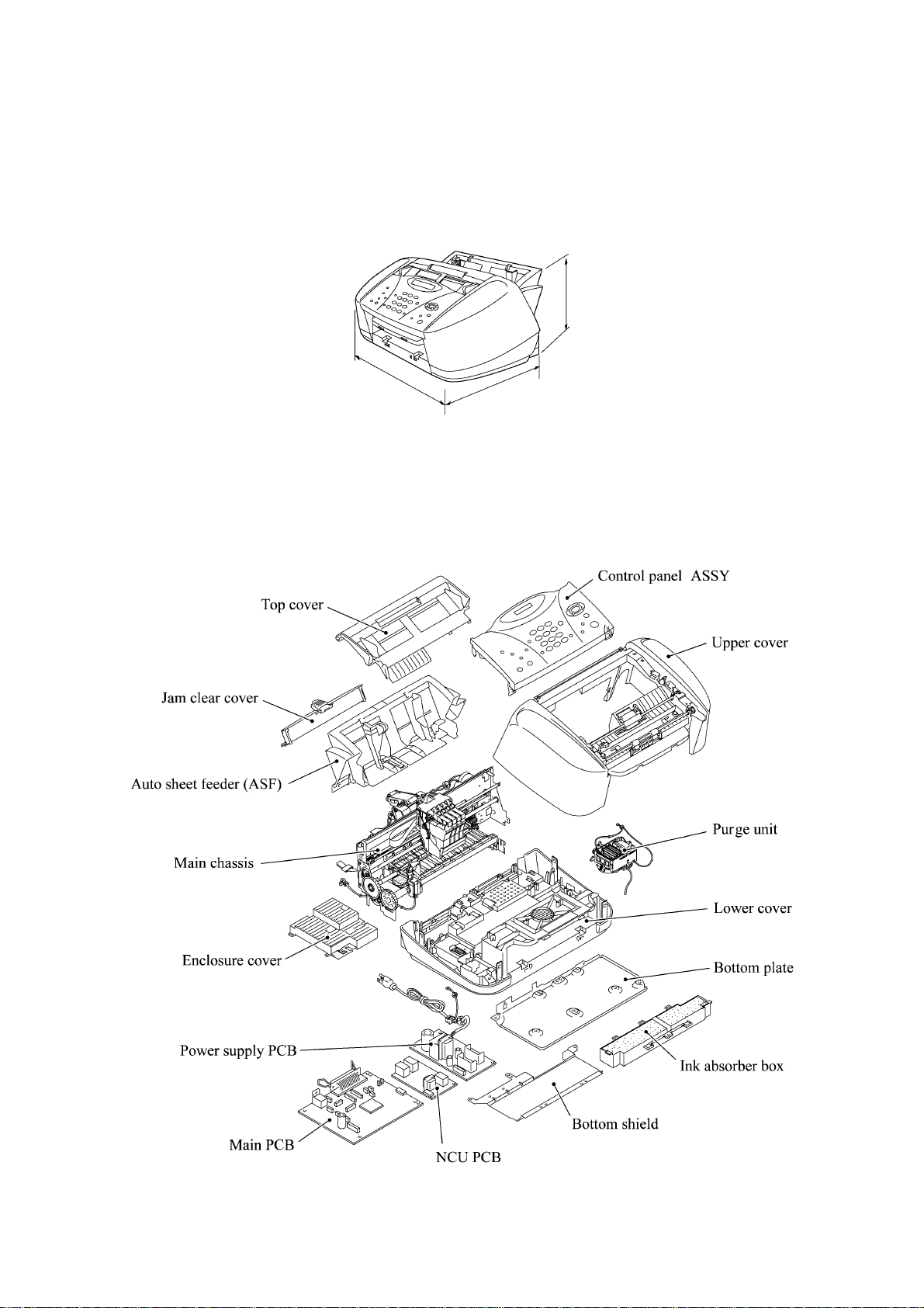
1.1.2 Components
The equipment consists of the following major components:
(D)
342 mm
13.5"
1-1
Page 7
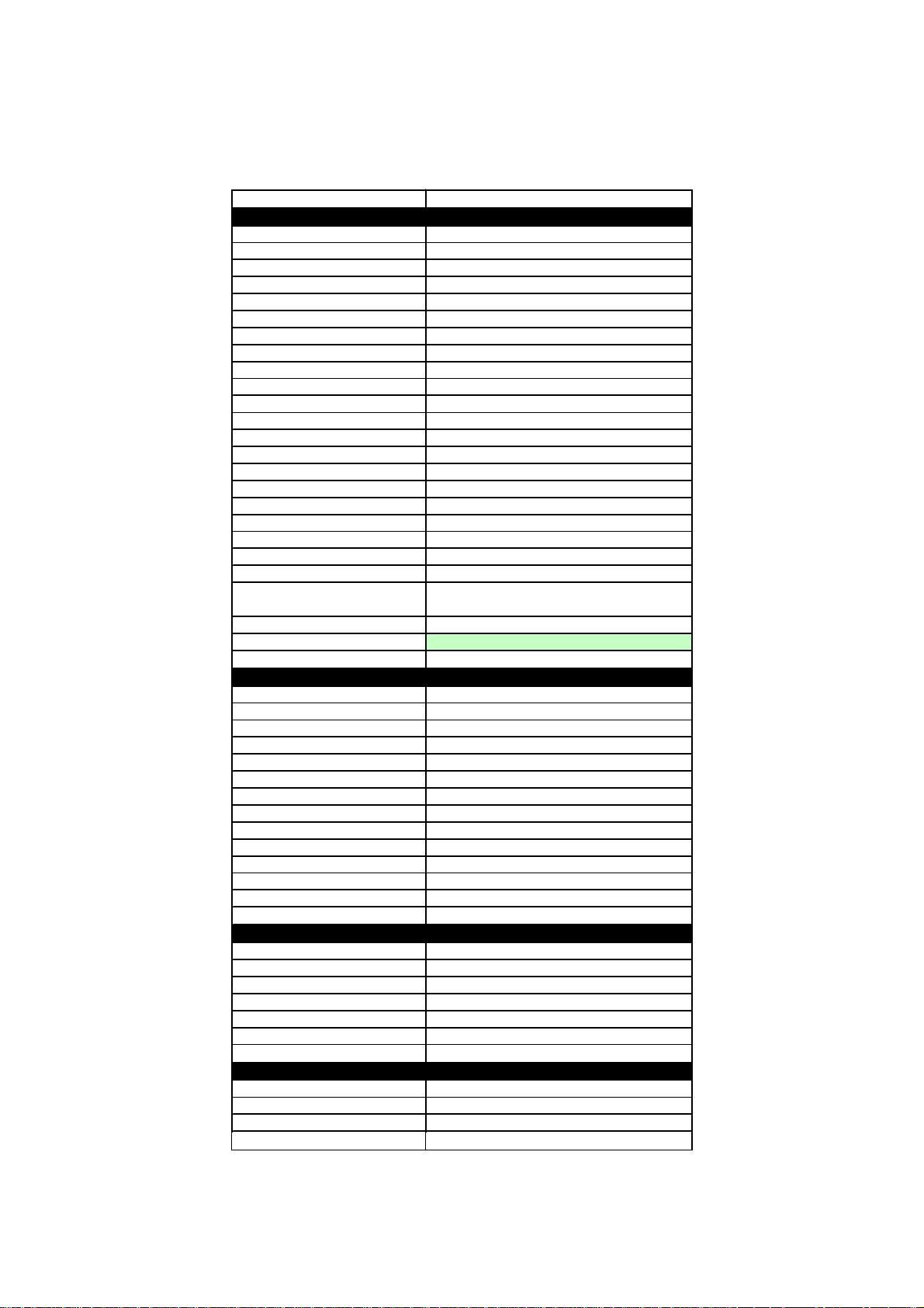
1.2 SPECIFICATIONS
Model Name MFC 3100C
GENERAL
Print Engine
Modem Speed (bps)
Transmission Speed (sec.)
ITU-T Group
Coding Method
Document/ Print Paper Width
Document/ Print Paper Length
Print Paper Margin (upper, lower, left, right)
ADF (pages)
LCD Columns
LCD Line
LCD Backlight
Backup Clock
Memory Backup
Memory Capacity (physical)
Optional Memory
Dimensions w/o Carton (WxDxH)
Dimensions w Carton (WxD xH)
Weight w/ o Carton
Weight w Ca rton
Color
Operating Environment Temperat ure
Humidity
Power Source
Power Consumption (Standby/Peak)
On/Off Switch
TELEPHONE
Handset
One-Touch Dial
Speed Dial
Speaker Phone
Chain Dialing
Caller ID
Call Waiting Caller ID
Distinctive Ringing
Hold/Mute Key
Hook Key
Power Failure Dialing
Speaker Volume
Ring Volume
Handset Volume
FAX
Scan Speed (A4:Standard)
Memory Transmission (Brother#1 Chart)
Memory Transmission (ITU-T Chart)
Out-of-Paper Reception (Brother #1 Chart)
Out-of-Paper Reception (ITU-T Chart)
Color FAX (Document Send/Receive)
Color FAX (Memory Send/Receive)
INTERFACE
External TAD Interface
Host Interface (IEEE1284)
Host Interface (USB)
LAN Interfa c e
Ink Jet (BH 2-head)
14,400 (Fax)
6 (Brother#1,MMR)
G3
MH/MR/MMR/JPEG
3.5"-8.5"/3.5"-8.5"
5.0"-14"/5.0"-14"
0.12, 0.43, 0.12, 0.12 inch (3,11, 3, 3 mm)
Up to 20
16 characters
Single line
No
Yes
N/A
2MB (RAM)
No
16.8"x13.5"x8.5" (426x342x217 mm)
20.4"x18.0"x14.8" (517x458x375 mm)
6.5kg/14.3lbs
10.5 kg/23.2lbs
Gray 1495
5 - 35 degrees Centigrade
60% +-25%
120VAC 50/60Hz
Under 7W/35W
No
No
No
Max. 40
No
Yes
No
No
Yes
No
No
No
No
Yes (2 steps + OFF)
No
Approx. 5 sec./page (A4:standard)
Yes (100:MMR)
Yes (85:MMR)
Yes (100:MMR)
Yes (85:MMR)
Yes/Yes
No/Yes
Yes
Yes
Yes
No
1-2
Page 8

Model Name MFC 3100C
PRINTER
Color/Mono
Engine Type
Resolution (dpi)
Piezo Ink Jet (2-head BH: 75 nozzles/color)
1200x1200 /2400x1200 (Mono/Color)
Color/Mono
10/8 (Mono/Color: 600*150)
Speed (ppm)
'4/3.5 (Mono/Color: 600*300)
'2/1.5 (Mono/Color: 600*600)
'0.2/0.2 (Mono/Color: 1200*1200/2400*1200)
Paper Capacity (sheets)
Output Paper Capacit y (sheets)
Standard Print Language
Emulation
Resident Fonts
Fonts Disk Based
Paper Handling Size
Manual Feed Slot
Other Paper Type
Sheet Weight (Paper Cassette)
(Manual Slot)
Printer Driver
COPY
Color/Mono
Speed (cpm)
Multi Copy(Stack)
Multi Copy (Sort)
Resolution (dpi)
SCANNER
Color/Mono
Resolution (dpi) (Phys i cal)
Resolution (dpi) (Logical)
Speed (ppm)
Gray Scale
TWAIN Compliant & Operating System
PCI Scanner (Parallel/Serial)
ACCESSORY
Cartridge
Life / Yield (Normal, 5% Coverage)
LTR, LGL, A4, B5 , A5, EXE, Post Card
64-120 g/m2 (17 - 32 lb)
Win95/98/98SE/Me/2000Professional/NT4.0/
Yes (B&W only) or Via PC
Max. 1200x1200 (color)
Win95/98/98SE/2000Professional/NT4.0/Me
4 colors (each separate tank)
Black: 950, Color: 450
100
50
Windows GDI
No
Yes
Yes
N/A
OHP, Envelopes
N/A
MacOS 8.5-9.1
Color/Mono
7/4
N/A or Via PC
Color/Mono
CIS: 300x600 (Opt.)
2400 (Int.)
Max. 5sec
256
MacOS 8.6-9.1
Parallel/USB
1-3
Page 9
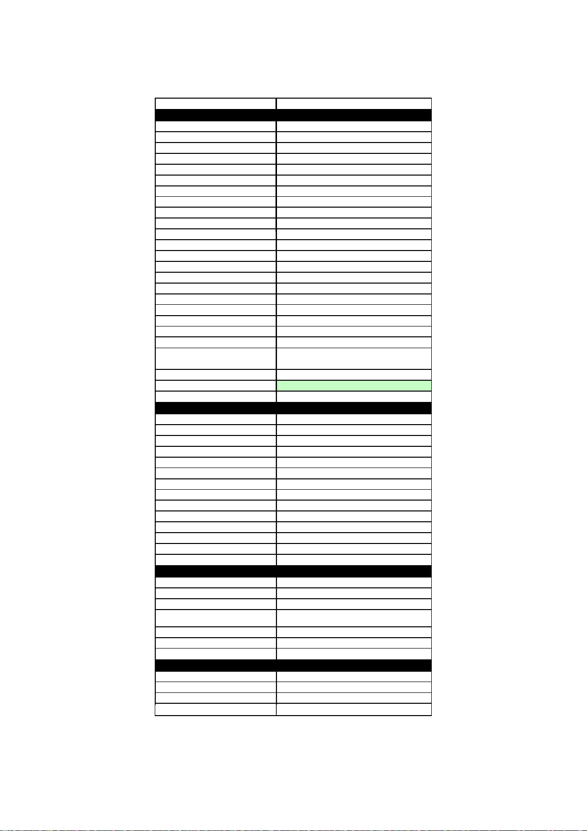
Model Name MFC-580
)
GENERAL
Print Engine
Modem Speed (bps)
Transmission Speed (sec.)
ITU-T Group
Coding Method
Document/Print Paper Width
Document/Print Paper Length
Print Paper Margin (upper, lower, left, right
ADF (pages)
LCD Colums
LCD Line
LCD Backlight
Backup Clock
Memory Backup
Memory Capacity (Physical)
Optional Memory
Dimensions w/o Carton (WxDxH)
Dimensions w Carton (WxDxH)
Weight w/o Carton
Weight w Car ton
Color
Operating Environment Temperature
Humidity
Power Source
Power Consumption (Standby/Peak)
On/Off Switch
TELEPHONE
Handset
One-Touch Dial
Speed Dial
Speaker Phone
Chain Dialing
Caller ID
Call Waiting Caller ID
Distinctive Ringing
Hold/Mute Key
Hook Key (Tel key)
Power Failure Dialing
Speaker Volume
Ring Volume
HandSet Volume
FAX
Scan Speed (A4:Standard)
Memory Transmission (Brother#1 Chart)
Memory Transmission (ITU-T Chart)
Out-of-Paper Reception (Brother #1 Chart)
Out-of-Paper Reception (ITU-T Chart)
Color FAX (Document Send/Receive)
Color FAX (Memory Send/Receive)
INTERFACE
External TAD Interface
Host Interface (IEEE1284)
Host Interface (USB)
LAN Interface No
0.12, 0.43, 0.12, 0.12 inch (3,11, 3, 3 mm)
16.8"x13.5"x8.5" (426x342x217 mm)
20.4"x18.0"x14.8" (517x458x375 mm)
Ink Jet (BH 2-head)
14,400 (Fax)
6(Brother#1,MMR)
G3
MH/MR/MMR/JPEG
90-216/90-216mm
127-356/127-356mm
Up to 20
16 characters
1 Line
N/A
Yes (1 hour)
N/A
2MB as spec.(Actually 8MB)
No
6.5kg/14.3lbs
10.5 kg/23.2lbs
Gray 1495
5 - 35 degrees Centigrade
60% +-25%
240VAC 50/60Hz
Under 6W/35W
No
N/A
N/A
40
No
Yes
No
No
Yes (only for UK, Denmark)
No
Tel (for F/T switch)
No
No
Yes (2 steps + OFF)
No
Approx. 5 sec./page (A4:standard)
Yes (100:MMR)
Yes (85:MMR)
Yes (100:MMR)
Yes (85:MMR)
Yes/Yes
No/Yes
Yes
Yes
Yes
1-4
Page 10

Model Name M FC-580
PRINTER
Color/Mono
Engine Type
Resolution (dpi)
Piezo Ink Jet (2-head BH: 75 nozzles/colour)
1200x1200/2400x1200 (B&W/Colour)
Color/Mono
10/8 (Mono/Color: 600*150)
'4/3.5 (Mono/Color: 600*300)
Speed(ppm)
'2/1.5 (Mono/Color: 600*600)
'0.2/0.2 (Mono/Color:
1200*1200/2400*1200)
Paper Capacity (sheets)
Output Paper Capacity (sheets)
Standard Print Language
Emulation
Resident Fonts
Fonts Disk Based
Paper Handling Size
Manual Feed Slot
Other Paper Type
Sheet Weight (Paper Cassette)
(Manual Slot)
Printer Driver
COPY
Color/Mono
Speed (ppm)
Multi Copy (Stack)
Multi Copy (Sort)
Resolution (dpi)
SCANNER
Color/Mono
Resolution (dpi) (Physica l )
Resolution (dpi) (Logical)
Speed (ppm)
Gray Scale
TWAIN Compliant & Operating System
PCI Scanner (Parallel/Serial)
ACCESSORY
Cartridge
Life / Yield (Draft, 5% Coverage)
LTR, LGL, A4, B5, A5, EXE,
Photo card, Index card
64-105 g/m2 (17 - 28 lb)
Win95/98/98SE/Me/2000Professional/NT4.0/
Yes (B&W only) or Via PC
Win95/98/98SE/2000Professional/NT4.0/Me
4 colours (each separate tank)
Black: 950, Color: 450
100
50
Windows GDI
N/A
Yes
Yes
N/A
OHP, Envelopes
N/A
MacOS 8.5-9.1
Color/Mono
7/4
N/A or Via PC
Max. 1200x1200
Color/Mono
CIS: 300x600 (Opt.)
2400 (Int.)
Max. 5sec
256
MacOS 8.6-9.1
Parallel/ USB
1-5
Page 11

CHAPTER
INSTALLATION
2
Page 12

CHAPTER 2 INSTALLATION
CONTENTS
2.1 INSTALLING THE UPDATE DATA TO THE FACSIMILE MACHINE.............................2-1
2.2 SETTING ID CODES TO FACSIMILE MACHINES CONNECTED TO A SINGLE
PC VIA THE USB PORT..................................................................................................2-3
2.3 SETTING HEAD PROPERTY TO THE FACSIMILE MACHINE .....................................2-4
Page 13
2.1 INSTALLING THE UPDATE DATA TO THE
r
FACSIMILE MACHINE
If the program version is updated or the main PCB is replaced, then install the update program
onto the flash ROM of the main PCB.
The program installation requires a PC/AT-compatible computer (which is capable of running MSDOS or its compatible OS).
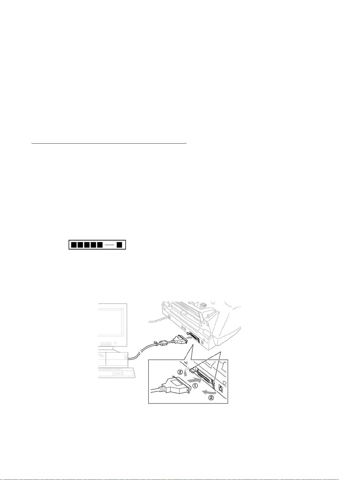
Connecting the facsimile machine to your PC
(1) Make sure that your PC is turned off.
(2) Make sure that the machine's power cord is unplugged from a wall socket.
(3) Connect the parallel interface cable to the parallel port on the back of the machine and secure
it with the lock wires.
(4) Connect the other end of the interface cable to the printer port of your PC and secure it with
two screws.
(5) While pressing the 5 key on the machine's control panel, plug the machine's power cord into a
wall socket.
(6) Check to see that the following pattern displays on the LCD. If it does not display, go back to
step (2) above.
(7) Turn on your PC.
Parallel interface
cable
Lock wires
Host compute
2-1
Page 14

Installing the update data onto the flash ROM of the facsimile machine
NOTE: The following is an installation procedure example on a PC that is running Windows 95/98.
(1) Copy the update data and transfer utility onto the desired directory of the hard disk.
e.g., C:\UPDATE
(2) Click the Start button, point to Programs, and then click MS-DOS Prompt to open an MS-DOS
window.
(3) Type the drive letter where the update data and transfer utility are located. In the above
example, type C:\ from the command line and press the ENTER key.
Then type CD UPDATE and press the ENTER key.
(4) Check that your PC is connected with the facsimile machine correctly.
(5) To start the transfer utility transmitting the update data to the flash ROM of the facsimile
machine, type the following:
ICEN filename /b
Then press the ENTER key.
During downloading, the machine beeps intermittently.
Upon completion of the downloading, the machine beeps continuously.
NOTE: If the facsimile machine cannot return to the standby state af ter completion of downloading,
turn the power off and on.
2-2
Page 15

2.2 SETTING ID CODES TO FACSIMILE MACHINES CONNECTED TO A SINGLE PC VIA THE USB PORT
Function
Brother facsimile machines are assigned unique ID codes (character strings) at the factory. If you
replace the main PCB of the machine, the machine will lose its assigned ID code so that it will not
be identified by the connected PC.
To connect those machines to a PC via USB, you need to assign ID codes (character strings) to
those individual machines according to the procedure given here. For models covered by this
manual, set serial numbers given to individual machines as ID codes.
Connecting each of facsimile machines to your PC
(1) Make sure that your PC is turned off.
(2) Make sure that the machine's power cord is unplugged from a wall socket or other power
source.
(3) Connect the interface cable to the parallel interface port on the back of the facsimile machine
and secure it with the lock wires.
(4) Connect the other end of the interface cable to the printer port of your PC and secure it with
the two screws.
(5) Plug the machine's power cord into a wall socket or other power source.
(6) Turn on your PC.
Operating Procedure
(1) On your PC, run the ID setup utility. Follow the instructions shown on the PC's screen and
enter the 9-digit serial number (e.g., G01012345) printed on the nameplate labeled to the back
of the facsimile machine as an ID code. Then press the Enter key.
The ID setting utility will transmit the ID code data from your PC to the facsimile machine
and then it will terminate.
The facsimile machine will automatically return to the standby mode.
(2) To check whether the entered character string (ID code) is correct, make the machine enter the
maintenance mode (refer to CHAPTER 5, Section 5.1) and then press the 1 key twice
(Subsection 5.3.5).
The facsimile machine will print out a Configuration List. At the right top of the list, "SER.#:
BROXXXXXXXXX" is printed.
(3) Check that the character string entered in step (2) is printed in "XXXXXXXXX."
If it is OK, press the 9 key twice to exit from the maintenance mode.
If something other than that is printed in XXXXXXXXX, check the connection between the
PC and facsimile machine and go back to step (1).
2-3
Page 16

2.3 SETTING HEAD PROPERTY TO THE FACSIMILE MACHINE
Function
To keep the print quality, the controller optimizes the head drive strength, ink jet-out timing, and
other drive conditions depending upon the electromechanical properties unique to the individual
print head and ambient temperature. For that, the controller reads the head property information
stored in the EEPROM of the main PCB.
If you replace the print head unit and/or main PCB of the machine, then you need to update the
head property according to the procedure given here.
Connecting the facsimile machine to your PC
(1) Make sure that your PC is turned off.
(2) Make sure that the machine's power cord is unplugged from a wall socket or other power
source.
(3) Connect the interface cable to the parallel interface port on the back of the facsimile machine
and secure it with the lock wires.
(4) Connect the other end of the interface cable to the printer port of your PC and secure it with
two screws.
(5) Plug the machine's power cord into a wall socket or other power source.
(6) Turn on your PC.
Operating Procedure
(1) On your PC, run the head property setup utility. Follow the instructions shown on the PC's
screen and enter upper 12 digits (e.g., 55557B657031) out of the 13-digit property code
(enclosed with asterisks, e.g., *55557B657031H*) which is printed on the bar code label
attached to the print head unit.
The utility will transmit the head property from your PC to the facsimile machine and then it
will terminate.
The facsimile machine will automatically return to the standby mode.
(2) To check whether the entered head property is correct, make the machine enter the
maintenance mode (refer to CHAPTER 5, Section 5.1) and then press the 7 key twice
(Subsection 5.3.15).
The facsimile machine will print out the Equipment's Log. On the line about 1/3 of full length
of the log sheet below from the top, the 12-digit code is printed.
(3) Check that the character string entered in step (2) is printed in "XXXXXXXXXXXX."
If it is OK, press the 9 key twice to exit from the maintenance mode.
If something other than that is printed in XXXXXXXXXXXX, check the connection between
the PC and facsimile machine and go back to step (1).
2-4
Page 17

CHAPTER
THEORY OF OPERATION
3
Page 18

CHAPTER 3 THEORY OF OPERATION
CONTENTS
3.1 OVERVIEW ......................................................................................................................3-1
3.2 MECHANISMS.................................................................................................................3-2
3.2.1 Scanner Mechanism ............................................................................................3-3
3.2.1.1 Document feeding and ejecting mechanism................................................3-3
3.2.1.2 Scanner........................................................................................................3-3
3.2.2 Ink Jet Printing Mechanism..................................................................................3-4
3.2.2.1 Paper pulling-in, registration, feeding, and ejecting mechanisms................3-4
3.2.2.2 Ink jet printing and capping mechanisms.....................................................3-6
3.2.2.3 Purging mechanism .....................................................................................3-9
3.2.2.4 Carriage drive mechanism .........................................................................3-12
3.2.3 Sensors and Actuators.......................................................................................3-13
3.3 CONTROL ELECTRONICS...........................................................................................3-16
3.3.1 Configuration......................................................................................................3-16
Page 19
3.1 OVERVIEW
3-1
Page 20
3.2 MECHANISMS
The facsimile machine is classified into the following mechanisms:
SCANNER MECHANISM - Document feeding and ejecting mechanism
INK JET PRINTING MECHANISM - Paper pulling-in, registration, feeding, and ejecting
SENSORS AND ACTUATORS
- Document scanning mechanism
mechanisms
- Ink jet printing and head capping mechanisms
- Purging mechanism
- Carriage drive mechanism
Document feeding and
ejecting mechanism
Document scanning
mechanism
Ink jet pri nting and head
capping mechanisms
Purge mechanism
Carriage drive mechanism
Paper pulling-in,
registration, feeding, and
ejecting mechanisms
SCANNER
MECHANISM
INK JET
PRINTING
MECHANISM
3-2
Page 21
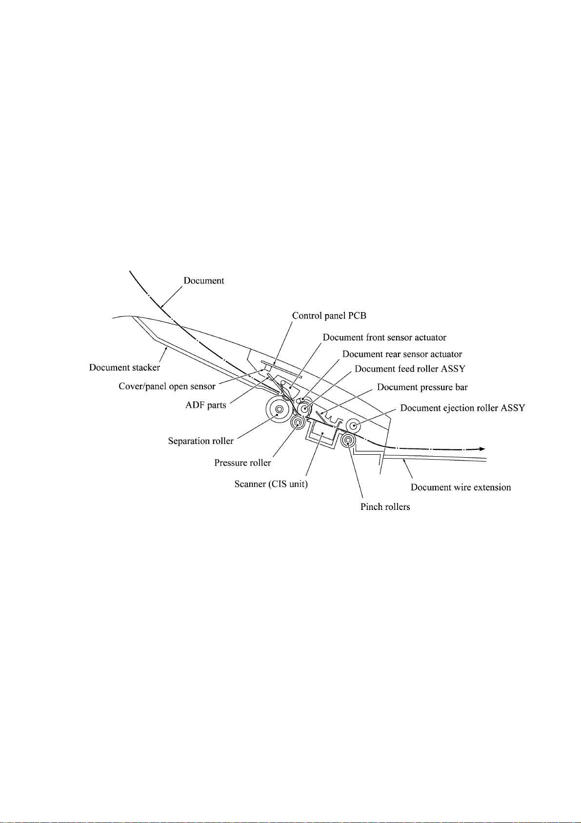
3.2.1 Scanner Mechanism
3.2.1.1 Document feeding and ejecting mechanism
This mechanism consists of the document stacker, automatic document feeder (ADF), document
feed roller ASSY, document ejection roller ASSY, and document sensors. (For details about the
sensors, refer to Subsection 3.2.3.)
If you set documents on the document stacker with their faces down and start the scanning
operation, then the scanner motor rotates so that the ADF (which consists of the separation roller
and ADF parts) feeds those documents into the machine, starting from the bottom sheet (first page)
to the top (last page), page by page. Each document advances with the document feed roller ASSY
to the scanner, and then it is fed out of the machine with the document ejection roller ASSY.
3.2.1.2 Scanner
The scanner uses a contact image sensor (CIS) unit which consists of an LED array illuminating
documents, a self-focus lens array collecting the reflected light, a CIS PCB carrying out
photoelectric conversion to output picture element data, and a cover glass on which a document
advances. When the document passes between the document pressure bar and the cover glass, it is
scanned.
3-3
Page 22
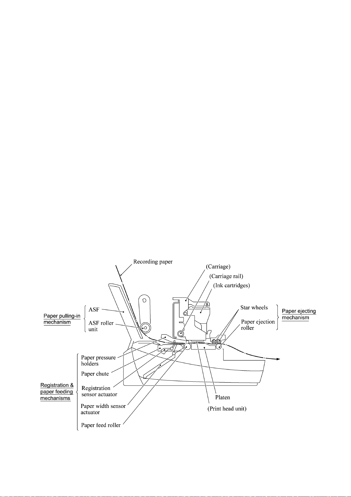
3.2.2 Ink Jet Printing Mechanism
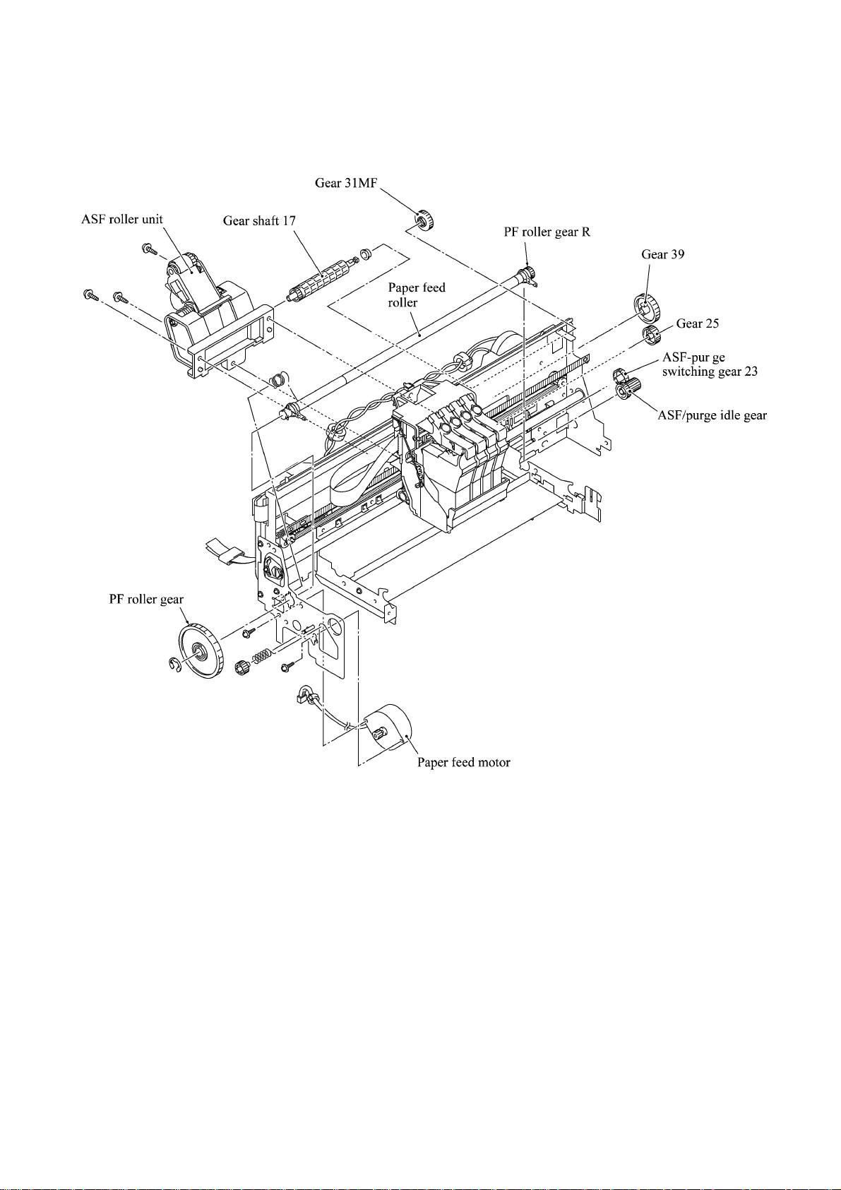
3.2.2.1 Paper pulling-in, registration, feeding, and ejecting mechanisms
The paper pulling-in, registration, feeding, and ejecting mechanisms are driven by a single paper
feed motor located at the left side of the main chassis via the gear train. (See the illustration given
on the next page.)
First, the paper feed motor rotates clockwise (when viewed from the output gear). The rotation is
transmitted to the PF roller gear that rotates paper feed roller. At the right end of the paper feed
roller is the PF roller gear R which is always engaged with the ASF/purge idle gear. Engaged with
the ASF/purge idle gear, the ASF-purge switching gear 23 transmits the rotation via gear 25 and
the ASF gear train to the ASF roller unit. This way, the ASF roller will pull in paper.
When the ASF roller is pulling in paper, the paper feed roller rotates in the backward direction to
register the leading edge of the pulled-in paper.
Next, the paper feed motor rotates counterclockwise to rotate the paper feed roller in the forward
direction. The paper will advance through the paper path. During the paper feeding operation, no
rotation is transmitted to the ASF roller because of the planetary gear system built in the ASF
roller unit.
The above paper pulling-in and feeding operations take place when the carriage is in printing
operation. If the carriage reaches the purge position, the ASF-purge switching gear 23 will be
disengaged from the gear 25 and engaged with purge bevel gear A. For the purging mechanism,
refer to Subsection 3.2.2.3.
3-4
Page 23
3-5
Page 24
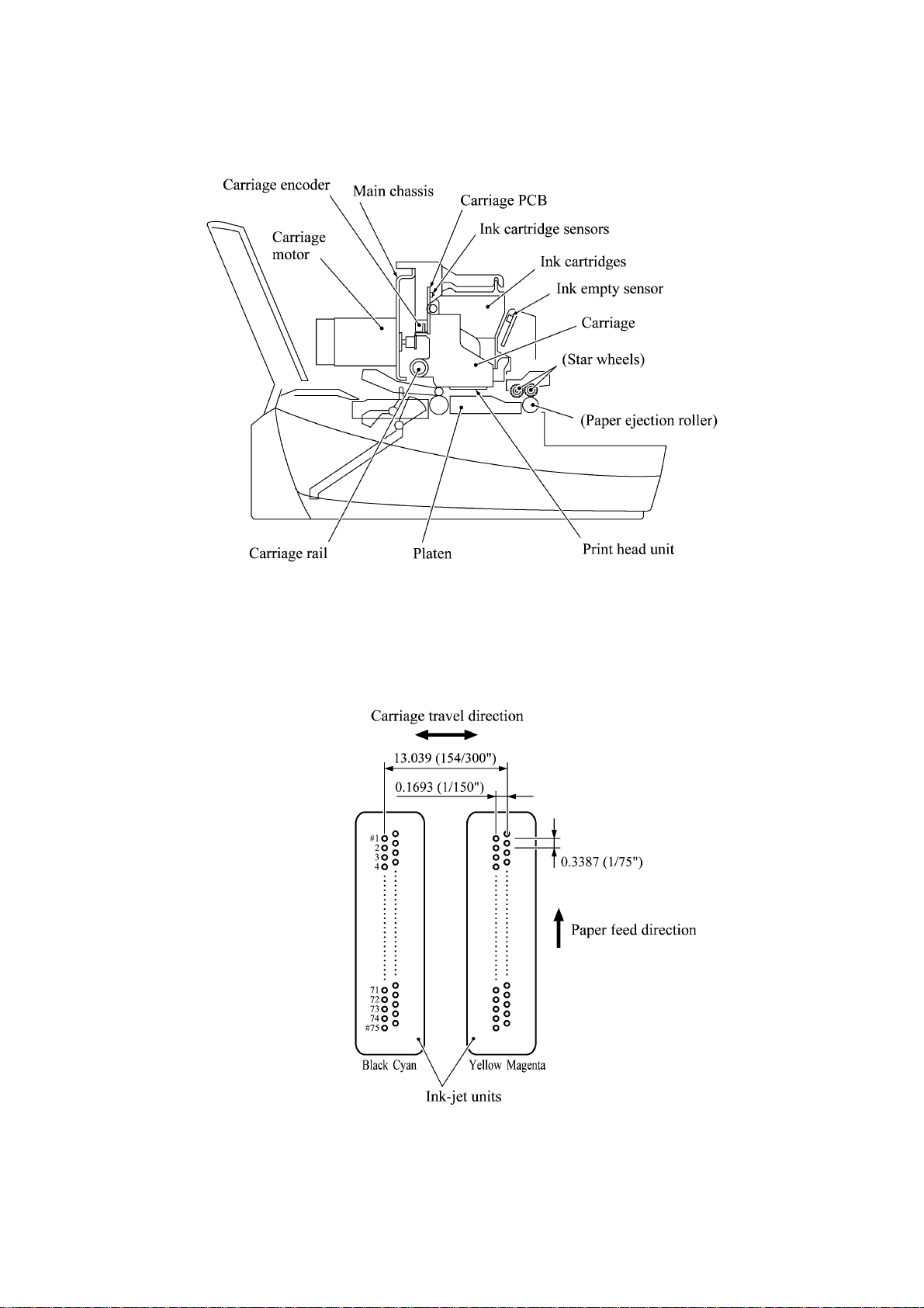
3.2.2.2 Ink jet printing and capping mechanisms
(1) Print head unit
This machine uses drop-on-demand ink jet printing. Each of the right and left print heads has an
ink-jet unit that has a pair of nozzle columns for two color inks. A nozzle column consists of 75
nozzles, 75 channels covered with piezoelectric ceramic (PZT), a manifold, and filter. As
illustrated below, the pair of nozzle columns is staggered.
Nozzle Layout (viewed from the bottom)
3-6
Page 25
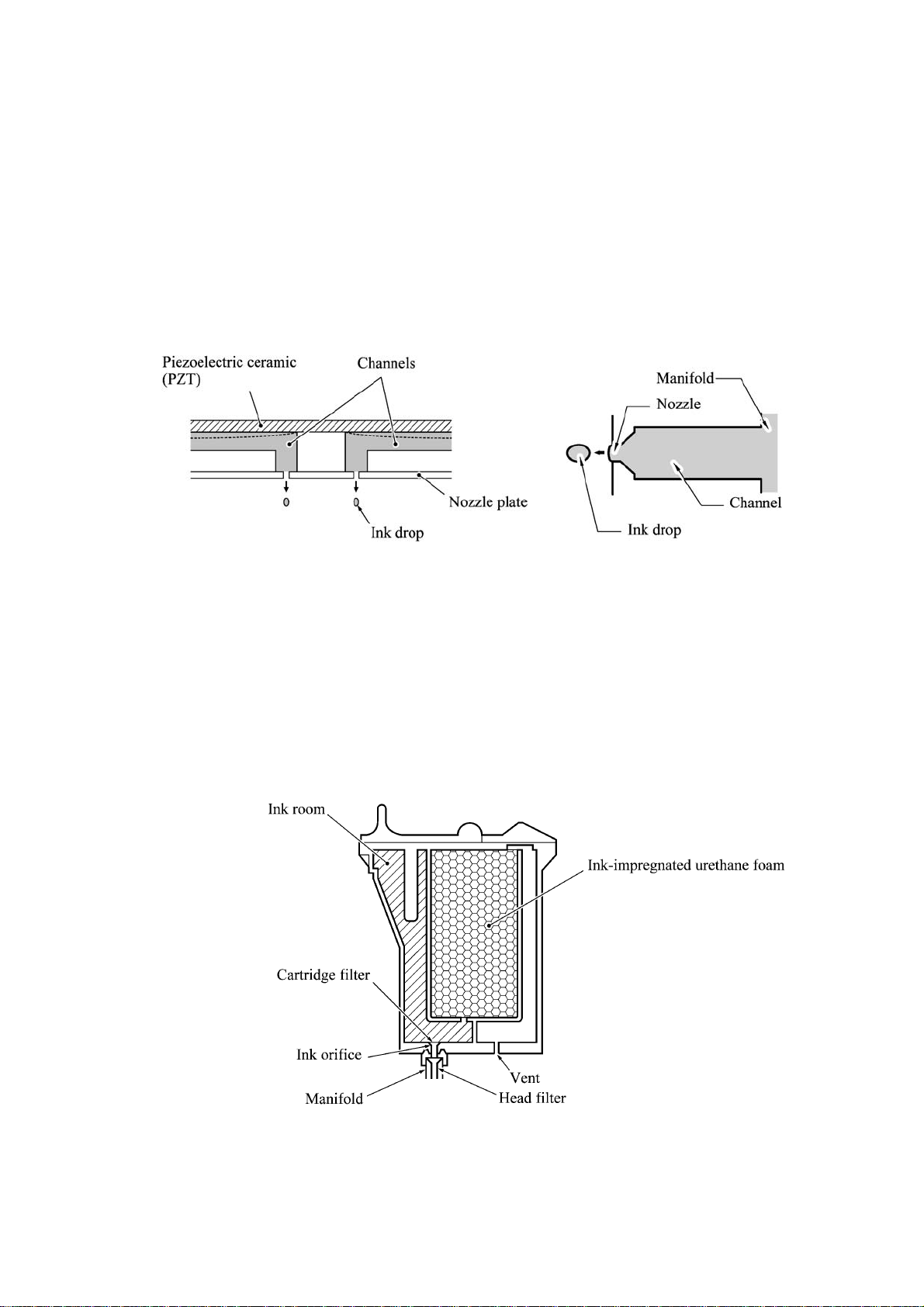
If the controller issues a print command, a biased voltage will be applied to all electrodes formed
on the surface of the piezoelectric ceramic so that each actuator will be distorted as shown with
broken lines.
If the electrodes on a target channel are deenergized according to drive signals, then the associated
piezoelectric ceramic actuator returns to the previous form so that the ink in the manifold will be
vacuumed out to the channel.
If the voltage is applied again, the piezoelectric ceramic actuator will be distorted again to apply
pressure to the ink in the channel, causing the ink to jet out through the nozzle. The jetted-out ink
drop will be splashed and produce a dot on paper held by the platen.
As the carriage holding the print head unit travels at the printing speed, the controller sends print
command pulses to the piezoelectric actuator driver circuit embedded in the print head unit.
(2) Ink cartridges
The machine uses four ink cartridges (black, cyan, yellow, and magenta) of disposable type to
supply ink to the print head unit. As shown below, an ink cartridge contains an ink-impregnated
urethane foam. If ink-jet print operation or purging operation takes place, ink comes out of the
urethane foam and is supplied to the print head unit through the ink room, filters, and manifold.
For the ink cartridge sensors on the carriage PCB, refer to Subsection 3.2.3.
3-7
Page 26
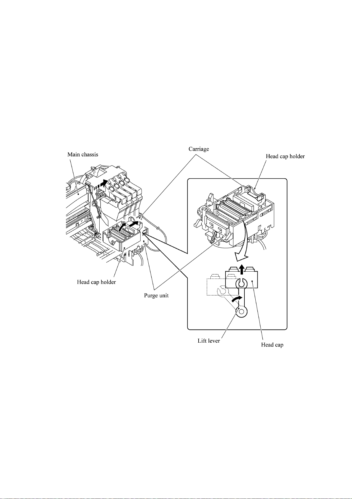
(3) Head cap
Shown below is a head cap mechanism that prevents the nozzles of the print heads from drying up
when they are not in use.
Upon completion of printing, the carriage travels to the right and moves the head cap holder
provided on the purge unit to the right together. In the head cap holder is a head cap which is
supported with a lift lever. The rightward movement of the head cap holder turns the lift lever and
pushes up the head cap to the position where the head cap comes into tight contact with the print
heads. This way, the nozzles will be capped.
3-8
Page 27
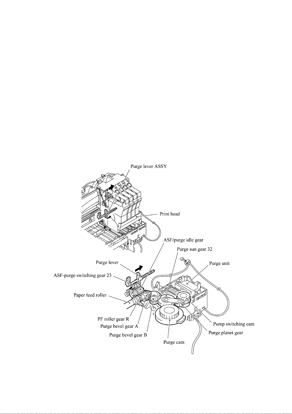
3.2.2.3 Purging mechanism
The purge mechanism is driven by the paper feed motor located at the left side of the main chassis.
As described in Subsection 3.2.2.1, the motor rotation is transmitted to the ASF/purge idle gear at
the right side of the main chassis. Engaged with the ASF/purge idle gear, the ASF-purge switching
gear 23 works as a clutch gear.
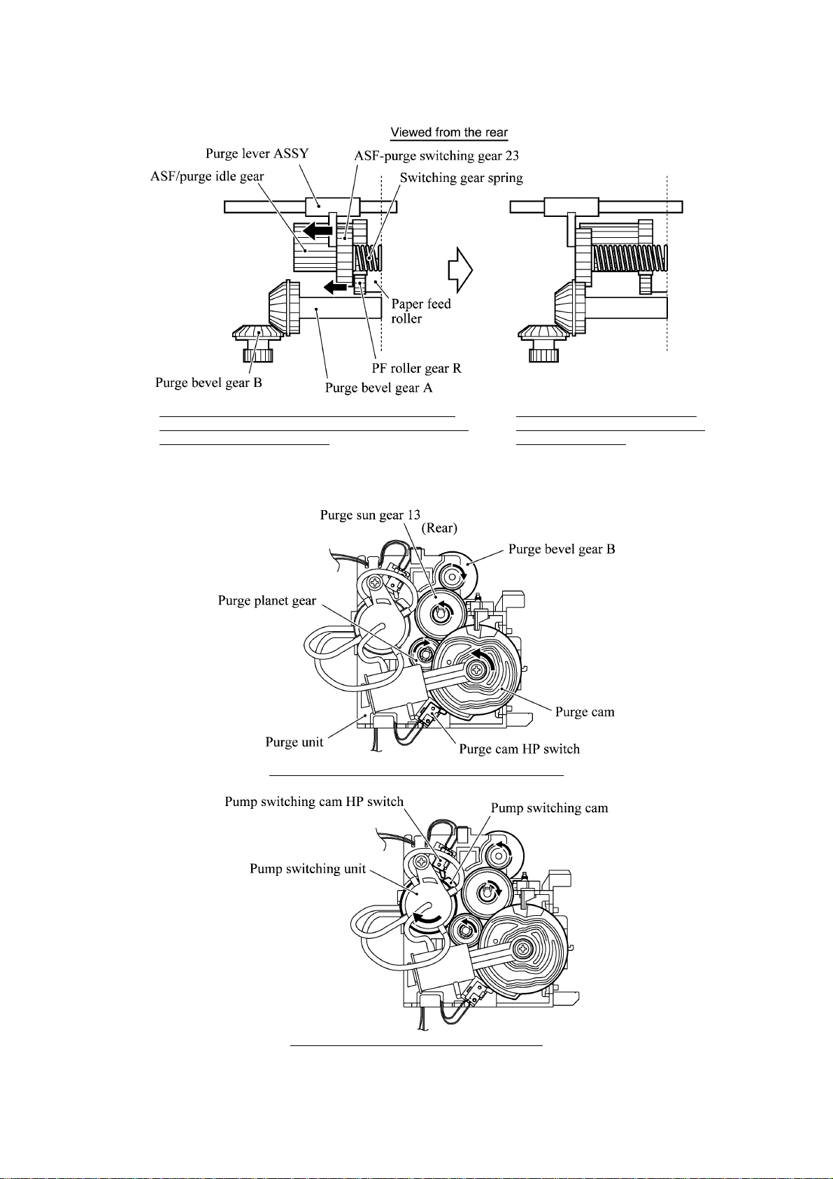
When the carriage travels from the left to right to reach the purge position, the tab provided on the
back of the carriage pushes the purge lever on the main chassis to the right (see the illustration
below). Accordingly, the ASF-purge switching gear 23 (which was shifted to the left by the purge
lever) will move to the right by the switching gear spring so as to become disengaged from the
gear 25 and engaged with the purge bevel gear A. (See the illustration given on the next page.)
This engagement will transmit the motor rotation to the purge bevel gear B on the purge unit. This
way, when the carriage is in the purge position, the motor rotation is transmitted to the purge unit.
On the contrary, if the carriage travels from the purge position to the left, the tab on the back of the
carriage releases the purge lever which will be pulled back to the left. The ASF-purge switching
gear 23 will be disengaged from the purge bevel gear A.
3-9
Page 28
During printing: The ASF-purge switching gear 23 is
not engaged with pur ge bevel gear A ( but engaged with
gear 25 in the ASF gear train).
During purging: T he ASF-purge
switching gear 23 is engaged with
purge bevel gear A.
When the motor rotation is transmitted to the purge unit, its counterclockwise rotation will drive
the purge cam and its clockwise rotation, the pump switching unit (when viewed from the output
gear of the motor).
When the paper feed motor rotates counterclockwise
When the paper feed motor rotates clockwise
3-10
Page 29
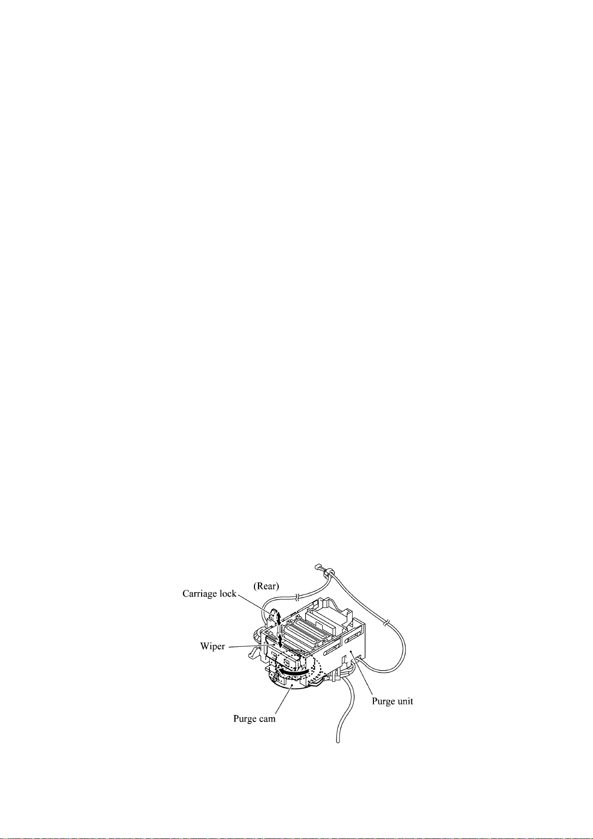
The purge cam is so designed that:
- the carriage lock pops out to lock the carriage before purging and pops in before cleaning with
the head wiper (see the illustration below),
- the pump works to draw out ink from each of the four head nozzles and drain it to the ink
absorber felts, and
- the head wiper comes out to clean the nozzle surface (see the illustration below).
The pump switching cam is so designed that:
- the pump switching unit switches application of the pump's negative pressure between the four
head nozzles in the order of black, cyan, yellow, and magenta nozzles. When the pump
switching cam is in the home position, normal atmospheric pressure will be restored.
The home position of the purge cam and pump switching cam are detected by their HP switches.
For those switches, refer to Subsection 3.2.3.
(1) Carriage lock
If the purge cam is driven, the carriage lock of the purge unit pops out and locks the carriage to
align ink-jet unit with the mating purge caps during purge operation. After purging but before
cleaning with the head wiper, it pops in to release the carriages. When the power is off, the
carriage lock keeps the print heads pressed against the head caps.
(2) Purging
If activated, the pump draws out ink to purge air bubbles or dust from the inside of the head
nozzles and channels. As the purge cam rotates by one turn, the piston of the pump reciprocates
two strokes. To complete purging of all four nozzles and channels, the purge cam rotates by two
turns ad the piston reciprocates four strokes.
(3) Draining
The pump drains drawn ink into the ink absorber felts.
(4) Cleaning with the head wiper
After purging operation, the head wiper comes out and the carriage moves from the right to left so
as to clean ink remaining on the heads' surface.
(5) Restoring the pump's pressure to normal atmospheric pressure
When the pump switching cam is in the home position, the controller stops to produce negative
pressure and restore the pump's pressure to normal atmospheric pressure.
3-11
Page 30
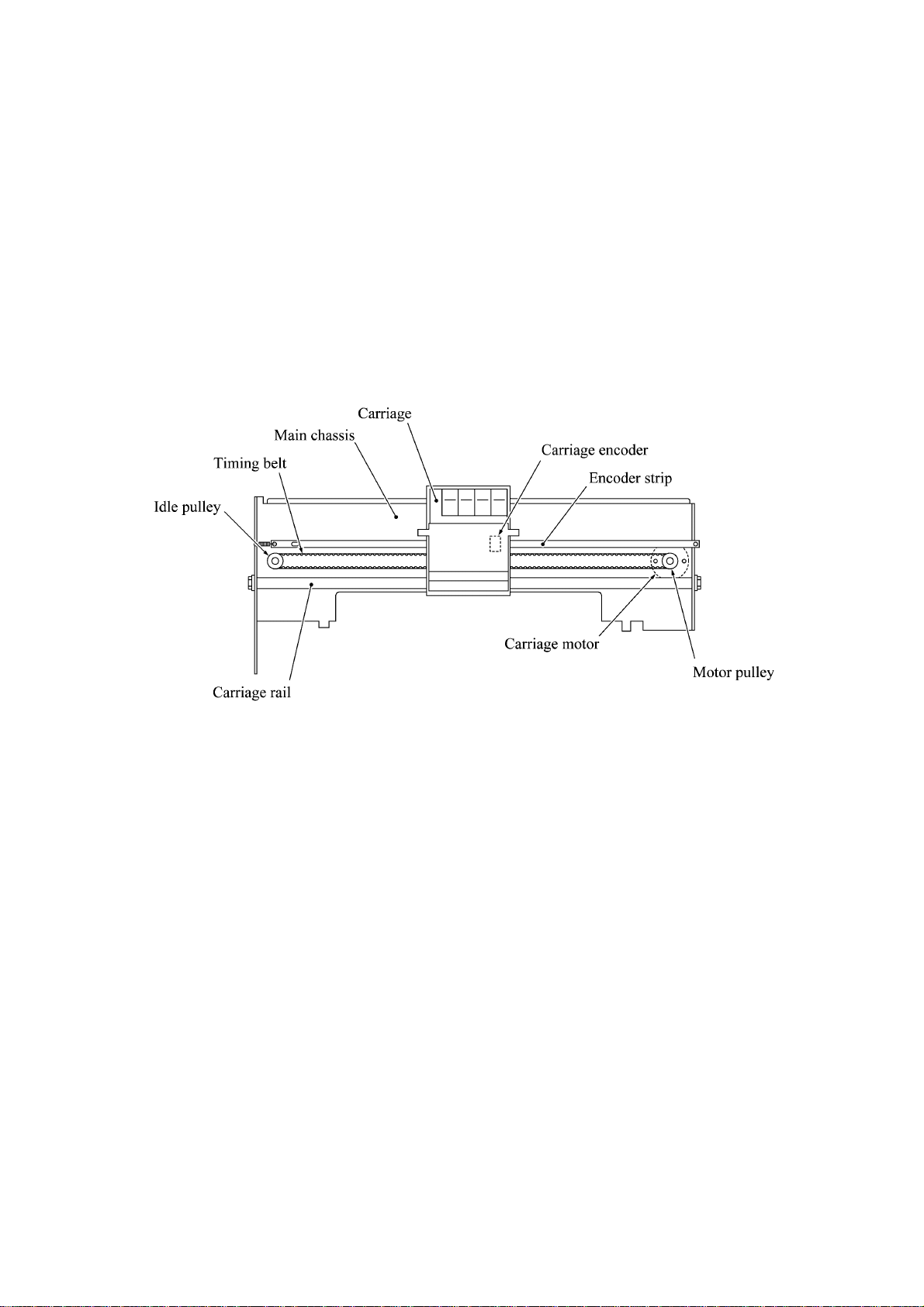
3.2.2.4 Carriage drive mechanism
The carriage motor controls horizontal motion. The motor rotation is transmitted via the motor
pulley to the timing belt.
The carriage, which is supported and guided by the carriage rail, is secured to the timing belt.
Clockwise and counterclockwise rotations of the carriage motor move the carriage to the right and
left, respectively.
On the back of the carriage is the carriage encoder which tells the control circuitry the current
carriage position counted based on the carriage motor position by using the encoder strip attached
to the main chassis.
3-12
Page 31

3.2.3 Sensors and Actuators
This machine has the following sensors and thermister.
Sensor name Type Located on
Document front sensor Photosensor
Document rear sensor Photosensor
Control panel PCB
Cover/panel open sensor Mechanical switch
Registration sensor Photosensor Paper chute
Paper width sensor Photosensor Main PCB
Ink empty sensor Photosensor Sensor support
Ink cartridge sensors Mechanical switches
Carriage encoder Photosensor
Carriage PCB
Head thermister Thermister
Purge cam HP switch Mechanical switch
Purge unit
Pump switching cam HP switch Mechanical switch
• Document front sensor which detects the presence of documents.
• Document rear sensor which detects the leading and trailing edges of pages to tell the control
circuitry when the leading edge of a new page has reached the starting position and when the
scan for that page is over.
• Cover/panel open sensor which detects whether the top cover and control panel are closed.
• Registration sensor which detects the leading and trailing edges of paper, which allows the
controller to determine the registration timing and check paper jam.
• Paper width sensor which detects whether the paper width is "A4-size or wider" or "narrower
than A4-size."
• Ink empty sensor which detects at the start of printing whether any of the four ink cartridges is
near empty. According to this sensor signal, the controller may display "NEAR EMPTY XXX"
message.
• Ink cartridge sensors, each of which detects whether an ink cartridge is loaded.
• Carriage encoder which detects the current carriage position and carriage travel speed. If the
carriage travels speed varies abnormally, the controller regards it as a paper jam.
• Head thermister which allows the controller to control the temperature of the print heads.
According to the change of the thermister's internal resistance monitored, the control circuitry
regulates the drive voltage applied to the piezoelectric ceramic actuators on each print head
since the viscosity of the ink varies depending upon the temperature.
• Purge cam HP switch which detects whether the purge cam is in the home position.
• Pump switching cam HP switch which detects whether the pump switching cam is in the home
position.
3-13
Page 32

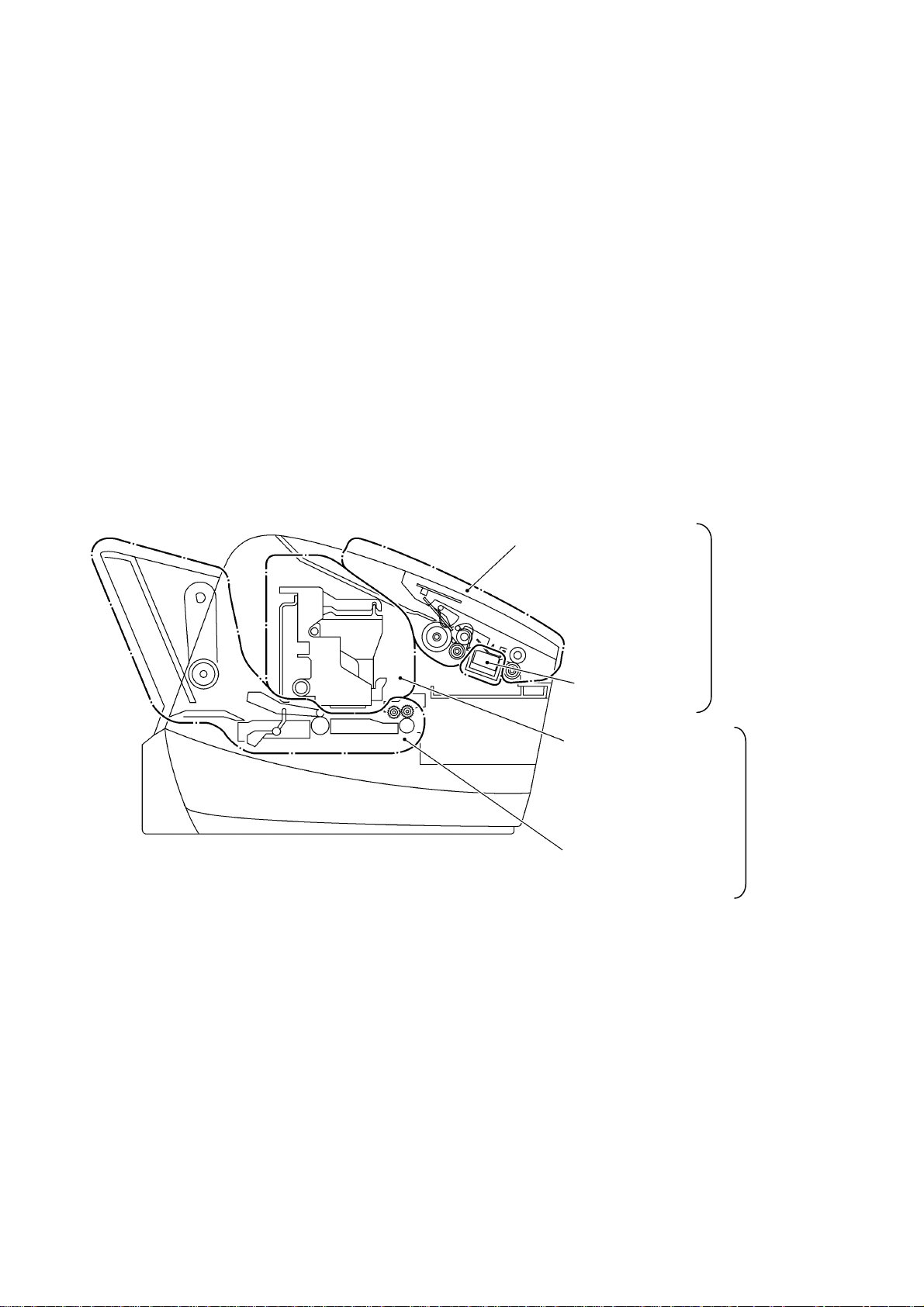
These photosensors (except the ink empty sensor that is a reflection type) are a photointerrupter
consisting of a light-emitting diode and a light-sensitive transistor. Each of them has an actuator
separately arranged as shown on the next page.
3-14
Page 33

Location of Sensors and Actuators
3-15
Page 34

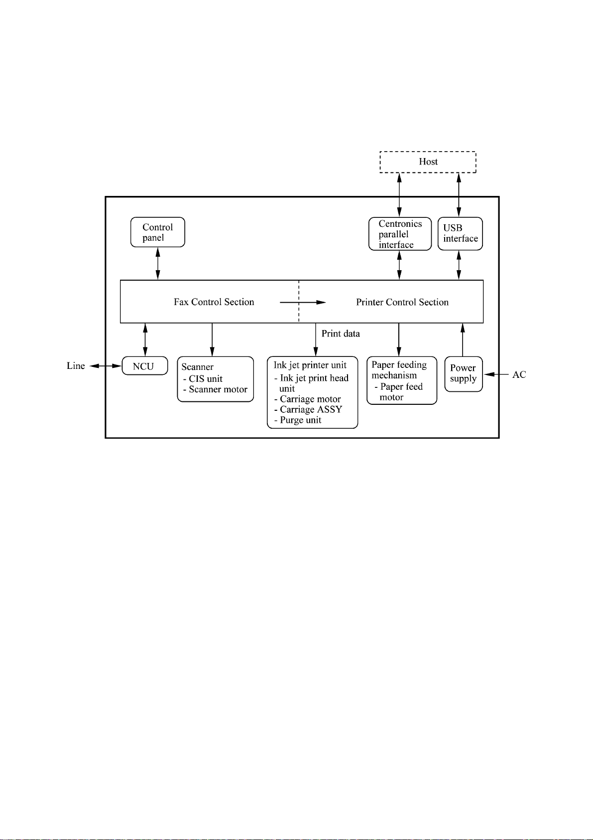
3.3 CONTROL ELECTRONICS
3.3.1 Configuration
The hardware configuration of the facsimile machine is shown below.
Configuration of Facsimile Machine
3-16
Page 35

CHAPTER
DISASSEMBLY/REASSEMBLY,
LUBRICATION, AND ADJUSTMENT
4
Page 36

CHAPTER 4 DISASSEMBLY/REASSEMBLY, LUBRICATION,
ADJUSTMENT
CONTENTS
4.1 DISASSEMBLY/REASSEMBLY......................................................................................4-1
Safety Precautions........................................................................................................4-1
Tightening Torque List......................................................................................................4-2
Preparation ...................................................................................................................4-3
How to Access the Object Component.........................................................................4-3
Disassembly Order Flow...............................................................................................4-4
4.1.1 Print Head Unit.....................................................................................................4-5
4.1.2 Jam Clear Cover and Auto Sheet Feeder (ASF)..................................................4-9
4.1.3 Bottom Plate, Ink Absorber Box, Main PCB, NCU PCB, and
Power Supply PCB.............................................................................................4-11
4.1.4 Enclosure Cover and Paper Width Sensor Actuator..........................................4-16
4.1.5 Top Cover...........................................................................................................4-17
4.1.6 Control Panel ASSY...........................................................................................4-18
4.1.7 Panel Rear Cover and Control Panel.................................................................4-19
4.1.8 CIS Unit..............................................................................................................4-22
4.1.9 Upper Cover.......................................................................................................4-23
4.1.10 Document Feed Roller ASSY, Document Ejection Roller ASSY,
Pressure Roller, and Pinch Rollers ....................................................................4-25
4.1.11 Panel Lock Springs, Scanner Chassis, Separation Roller,
Scanner Drive Unit, and Scanner Motor.............................................................4-26
4.1.12 Purge Unit ..........................................................................................................4-29
4.1.13 Main Chassis......................................................................................................4-31
4.1.14 ASF Roller Unit and its Related Gears...............................................................4-32
4.1.15 Roller Pressure Holders .....................................................................................4-34
4.1.16 Paper Chute and Registration Sensor................................................................4-35
4.1.17 Paper Ejection Roller Gear, Ink Empty Sensor PCB, Platen,
Star Wheel Support, and Paper Ejection Roller.................................................4-37
4.1.18 Paper Feed Motor and Paper Feed Roller .........................................................4-40
Page 37

4.1.19 Encoder Strip and Carriage Motor......................................................................4-41
4.1.20 Carriage Rail, Carriage ASSY, and Purge-Related Parts ..................................4-43
4.1.21 Flushing Box.......................................................................................................4-48
4.1.22 Harness Routing.................................................................................................4-49
4.2 LUBRICATION...............................................................................................................4-51
4.3 ADJUSTMENT...............................................................................................................4-56
Page 38

4.1 DISASSEMBLY/REASSEMBLY
Safety Precautions
To prevent the creation of secondary problems by mishandling, observe the following precautions
during maintenance work.
(1) Unplug the power cord from the power outlet before replacing parts or units. When having
access to the power supply, be sure to unplug the power cord from the power outlet.
(2) Be careful not to lose screws, washers, or other parts removed for parts replacement.
(3) When using soldering irons and other heat-generating tools, take care not to damage the resin
parts such as wires, PCBs, and covers.
(4) Before handling the PCBs, touch a metal portion of the machine to discharge static electricity;
otherwise, the electronic parts may be damaged due to the electricity charged in your body.
(5) When transporting PCBs, be sure to wrap them in conductive sheets such as aluminum foil.
(6) Be sure to reinsert self-tapping screws correctly, if removed.
(7) Tighten screws to the torque values listed on the next page.
(8) When connecting or disconnecting cable connectors, hold the connector bodies not the cables.
If the connector has a lock, always slide the connector lock to unlock it.
(9) Before reassembly, apply the specified lubricant to the specified points. (Refer to Subsection
4.2 in this chapter.)
(10) After repairs, check not only the repaired portion but also that the connectors and other related
portions function properly before operation checks.
(11) Once the print head unit prints, it will start head locking operation after five seconds from the
end of printing. The head locking operation will take 5 to 10 seconds. NEVER unplug the
power cord before the machine completes the head locking operation; doing so will make the
print head unit unusable and require replacement with a new print head unit.
When you receive the machine from the user or when you pack it for sending it back to the
user, check the head locking state.
4-1
Page 39

Tightening Torque List
Location Screw type Q'ty Tightening torque
N•m (kgf•cm)
ASF Taptite, bind B M4x12 4 0.8 8 ±0.10 (9 ±1)
Bottom plate Taptite, cup B M3x12 9 0. 7 8 ±0.10 (8 ±1)
Grounding terminal Screw, pan (washer) M 4x8 1 0.39 ±0.10 (4 ±1)
Bottom shield plate Taptite, cup B M3x12 2 0.78 ±0.10 (8 ±1)
Taptite, cup S M3x5 2 0.49 ±0.1 0 (5 ±1 )
Parallel & USB I/F connectors Screw, pan M3x6 3 0.39 ±0.10 (4 ±1)
FG plate R (Lower cover) Taptite, cup B M3x12 1 0.78 ± 0 .10 (8 ±1)
(Main chassis) Taptite, cup S M3x5 1 0.78 ± 0 .10 (8 ±1)
ADF parts Taptite, cup B M3x6 1 0.49 ± 0.10 (5 ±1)
Panel rear cover Taptite, cup B M3x8 2 0.88 ±0.10 (9 ±1)
CIS side spring Taptite, cup B M3x10 1 0.78 ±0.10 (8 ±1)
Upper cover Taptite, bind B M4x12 2 0.98 ±0.10 (10 ±1)
Panel lock spring R Taptite, cup S M3x5 1 0.98 ±0.10 (10 ±1)
Panel lock spring L Taptite, cup B M3x10 1 0 . 7 8 ±0.10 (8 ±1)
Scanner chassis Taptite, cup B M3x10 4 0.78 ±0.10 (8 ±1)
Scanner motor Screw, pan (s/p washer) M3x6DA 1 0.49 ±0.10 (5 ±1)
Purge unit Taptite, cup B M3x8 2 0.59 ±0.10 (6 ±1)
FG plate L Taptite, cup S M3x5 1 0.78 ±0.1 0 (8 ±1 )
ASF roller unit Taptite, cup S M3x6 3 0.98 ±0.10 (10 ±1)
ASF gear holders Taptite, cup B M3x10 1 0.4 9 ±0.10 (5 ±1)
Paper chute Taptite, cup S M3x6 1 0 .98 ±0.10 (10 ±1)
Sensor support Taptite, cup S M3x6 1 0.98 ±0.10 (10 ±1)
Ink empty sensor PCB Taptite, cup B M3x8 1 0.59 ±0.10 (6 ±1)
Platen Shoulder screw 1 0.59 ±0.10 (6 ±1)
Screw, bind B tite, M3x10 1 0.5 9 ±0.10 (6 ±1)
Platen plate R Taptite, bind B M2.6x10 1 0.3 9 ±0.10 (4 ±1)
Platen plate L Taptite, bind B M2.6x10 1 0.39 ±0 .1 0 (4 ±1 )
Paper feed motor Screw, pan (s/p washer) M3x6 2 0.78 ±0.10 (8 ±1)
Idle pulley holder Taptite, cup S M3x8 1 0.98 ± 0.10 (10 ±1)
Shoulder screw 1 0.78 ±0.10 (8 ±1)
Screw, cup S tite, M3x6 1 0.9 8 ±0.10 (10 ±1)
Carriage motor Screw, pan (s/p washer) M3x6 2 0.78 ±0.10 (8 ±1)
Eccentric bushings R, L Screw, pan (s/p washer) M3x6DB 2 0.78 ±0.10 (8 ±1)
4-2
Page 40

Preparation
Prior to proceeding to the disassembly procedure,
(1) Unplug
- the modular jack of the telephone line,
- the PC interface cable if connected (Not shown below), and
- the modular jack of an external telephone set if connected (Not shown below).
(2) Remove
- the document support,
- the paper wire extension,
- the document wire extension, and
- the paper tray.
NOTE: Do not remove the ink cartridges when disassembling the machine except when removing
the print head unit.
How to Access the Object Component
• On the next page is a disassembly order flow which helps you access the object components.
To remove the platen, for example, first find it on the flow and learn its number (
case). You need to remove parts numbered
platen.
• Unless otherwise specified, the disassembled parts or components should be reassembled in the
reverse order of removal.
in this
, , , , , and so as to access the
4-3
Page 41

Disassembly Order Flow
4-4
Page 42

4.1.1 Print Head Unit
During disassembly jobs (except when removing the purge unit, carriage rail, or carriage
ASSY), the print head unit and all the four ink cartridges should be kept in place.
NOTE: To replace the print head unit with a new one, you need to move the carriage to the ink
replacement position by placing the machine in the ink replacement mode. Do not move the
carriage by hand when the power is off.
NOTE: If you replace the print head unit with a new one, replace also the ink absorber box and
ink cartridges with new ones.
(1) Plug the power cord into a wall socket.
(2) Press the Ink key to place the machine in the ink replacement mode.
(3) Press the 2 key to choose "2. REPLACE INK."
(4) Press the Menu/Set key.
The carriage automatically moves to the ink replacement position.
(5) Unplug the power cord from the wall socket.
(6) Open the control panel ASSY and top cover.
(7) Push the colored ink cartridge covers and remove all ink cartridges. (Or, remove the shipping
cover.)
4-5
Page 43

(8) Pull the head clamp springs in the direction of arrows shown below to release the print
head unit.
(9) Lift the print head unit up and out of the carriage (arrow
).
NOTE: Do not touch the printing ends (nozzles) of the print head unit or the ink orifices of
the ink cartridges; doing so will not only stain your hands with ink but result in an ink jet-out
failure. Once you touch them, clean them with a dedicated cleaning stick and liquid.
NOTE: Be sure to put a head nozzle seal and filter seal on the print head unit as shown below.
Leaving the print head unit without those seals will dry up its printing ends and filters,
resulting in a damaged head.
NOTE: Do not touch the dimple contact section of the print head unit.
4-6
Page 44

NOTE: Once the ink cartridges are removed, their colored covers rise upright. If you turn the
machine upside down with those covers being upright, then they will break. To prevent it, set
them to the horizontal position by turning them in the direction of arrow
up in the direction of arrow
.
and pushing them
(10) Turn the head adjuster lever located on the right side of the carriage to position 1.
(11) To install a new (or removed) print head unit, remove the head nozzle seal.
(12) Put the print head unit into the carriage with care for the dimple contact so that the electrical
contact on the head PCB comes into uniform contact with that on the carriage PCB as
illustrated below.
4-7
Page 45

(13) Press the front center of the carriage to the rear and move the print head unit to the right and
left several times. This is to assure the dimple contact between the head PCB and carriage
PCB.
(14) While pressing the front center of the print head unit, lock the print head unit with the head
clamp springs.
(15) Remove the head filter seal.
(16) Set new ink cartridges into the carriage.
(17) Press the bottom right front corner of the carriage to the rear.
(18)Close the top cover and control panel.
(19) Plug the power cord into a wall socket.
The carriage automatically moves to the right-hand home position.
(20) Follow the instructions shown on the LCD.
NOTE: The machine enters a "head cleaning" cycle that takes approx. 3 minutes for each ink
cartridge.
(21) Load paper into the ASF.
(22) Correct the positioning error of the print head unit, referring to Section 4.3 "ADJUSTMENT."
(23) Adjust the alignment of vertical print lines, referring to CHAPTER 5, Subsection 5.3.12.
4-8
Page 46

4.1.2 Jam Clear Cover and Auto Sheet Feeder (ASF)
(1) Remove the jam clear cover.
(2) Remove the four screws from the ASF to release it.
(3) Pull out the separation pad ASSY.
4-9
Page 47

(4) Disassemble the separation pad ASSY as shown below.
4-10
Page 48

4.1.3 Bottom Plate, Ink Absorber Box, Main PCB, NCU PCB, and Power Supply PCB
(1) Disconnect the following harnesses and flat cables from the main PCB:
• Head flat cables
• Registration sensor harness
• Purge switch harness
• Ink empty sensor harness
• Panel-main harness
• CIS harness
• Scanner motor harness
• Carriage motor harness
• Paper feed motor harness
4-11
Page 49

(2) Remove three screws "e" from the rear of the machine (two for the parallel I/F connector and
one for the USB I/F connector).
(3) Turn the machine upside down.
NOTE: Cover the workbench with cloth to protect the top cover and control panel from
scratches or damages.
(4) Remove nine screws "a" from the bottom plate.
(5) Remove screw "b" from the grounding terminal.
(6) Remove four screws, two "c" and two "d" from the bottom shield.
4-12
"a" and "c": Taptite, cup B M3 x12
"b": Screw, pan M4x8
"d": Taptite, cup S M3x5
"e": Screw, pan M3x6
Page 50

(7) Push down the latch and remove the ink absorber box as illustrated below.
NOTE: Do not remove the ink absorber box unless it requires replacement. When replacing it,
set a new one soon after the removal to prevent the machine from getting stained with drained
ink.
NOTE: If the print head unit is replaced with a new one, replace also the ink absorber box
with new one.
NOTE: If the ink absorber box or the surrounding parts are stained with ink, wipe them with a
waste cloth.
4-13
Page 51

(8) Remove the screw from the FG plate R.
(9) Slightly pull up the FG plate R, pull two latches "a" outwards, and then lift up the power
supply PCB. Disconnect the power supply harness from the PCB.
(10) Slightly pull up the FG plate L and release the main PCB from it. Release the NCU PCB from
latch "b" and disconnect it from the main PCB.
(11) Disconnect the power supply harness from the main PCB.
Reassembling Notes
• Be sure to route the power supply harness as illustrated above. Route the other harnesses and
flat cables as illustrated in Subsection 4.1.22, "Harness Routing A." At the right rear corner, be
sure to hook the ferrite core of the scanner motor harness on the cable guide.
• After you replace the main PCB, be sure to follow the flowchart given on the next page.
• Be sure to route the grounding wire as illustrated on page 4-12.
4-14
Page 52

Setting up the main PCB after replacement
- - - - - - - - - - - - - - - - - - - - - - - - - - - - - - - - - - - - - Important - - - - - - - - - - - - - - - - - - - - - - - - - - - - - - - - - - - - - - NOTE: Before starting the following procedure, make sure that the print head unit is installed.
4-15
Page 53

4.1.4 Enclosure Cover and Paper Width Sensor Actuator
(1) While pulling up the FG plate R, lift up the enclosure cover.
(2) Slightly push down the locking arm and remove the paper width sensor actuator as shown
below.
4-16
Page 54

4.1.5 Top Cover
(1) Turn the machine back to the normal position.
(2) Open the control panel ASSY.
(3) Open the top cover (not fully) and lift it up and to the rear.
4-17
Page 55

4.1.6 Control Panel ASSY
(1) Open the control panel ASSY to you (in the direction of arrow ).
(2) Push the right and left arms of the control panel ASSY outwards (arrow
) to release those
arms from bosses "X" provided on the upper cover with a flat screwdriver.
(3) Open the control panel ASSY further, then take out the panel-main harness from the harness
guides provided on the panel rear cover and disconnect the panel-main harness from the
control panel PCB.
Reassembling Notes
• Route the panel-main harness along the three harness guides as illustrated above.
4-18
Page 56

4.1.7 Panel Rear Cover and Control Panel
(1) Place the control panel ASSY upside down.
If you do not need to remove the ADF parts, antistatic brush, or document rear sensor
actuator, skip to step (5).
(2) To remove the ADF parts (spring plates and separation rubber), remove the screw.
(3) To replace the antistatic brush, peel it off.
NOTE: Once removed, it will become unusable and a new part will have to be put back in.
(4) To remove the document rear sensor actuator, pull the actuator to the left and lift up the right
end of the actuator.
(5) Pull section "b" of the panel rear cover to the front to release the center tab of the document
pressure bar, turn up the document pressure bar, and pull either end of the document pressure
bar outwards to release it.
4-19
Page 57

(6) Remove the two screws from the panel rear cover.
(7) Unhook the panel rear cover from ten "X" latches provided on the control panel and lift up the
panel rear cover.
(8) Fully turn the document front sensor actuator to the rear and lift it up.
(9) Unhook the control panel PCB from seven "Y" latches.
(10) Slightly lift up the control panel PCB, then unlock the LCD cable connector and disconnect
the LCD flat cable. Next, unlock the FPC key connector and disconnect the FPC key.
4-20
Page 58

(11) As shown below, pull up the locking arm "x," slide the LCD to the right, pull the locking arm
"y" to the rear, and take out the LCD while pulling the LCD flat cable gently.
Reassembling Notes
• Before reinstalling the LCD to the control panel, wipe fingerprints or dust off the LCD surface
and control panel window with a soft cloth.
• A new LCD is covered with a protection sheet. Before installing it, remove the protection sheet.
4-21
Page 59

4.1.8 CIS Unit
(1) Remove the screw from the CIS side spring and lift it up.
(2) Move the CIS unit to the left and lift up the right edge of the CIS unit. While holding up the
CIS unit, disconnect the CIS harness. The CIS springs also come off.
Reassembling Notes
• After installation of the CIS unit, wipe fingerprints or dust off the CIS surface with a soft cloth.
4-22
Page 60

4.1.9 Upper Cover
(1) Remove the two screws from the upper cover.
(2) Disconnect the panel-main harness and CIS harness from the main PCB if you have not
removed the main PCB.
(3) Disconnect the scanner motor harness from the main PCB if you have not removed the main
PCB.
Remove the harness from the four cable guides (shown in Subsection 4.1.22 "Harness routing
A."
(4) Press the cover retainers R inwards with the tip of a flat screwdriver to release the rear hooks
provided on the inside of the upper cover.
(5) Lift up the upper cover while releasing the front hooks from the cover retainers F.
CAUTION: After removing the upper cover, do not turn the machine upside down. The main
chassis may be warped or distorted so that the print quality could deteriorate.
4-23
Page 61

Reassembling Notes
• Before installing the upper cover, make sure that the panel-main harness, CIS harness, and
scanner motor harness are routed properly on the inside of the upper cover. (Refer to
Subsection 4.1.22 "Harness Routing B" and "Harness Routing C."
• When installing the upper cover, take care not to bring the tab of the ASF roller unit inside the
upper cover. The tab should be fitted to the rear edge of the upper cover as illustrated below.
4-24
Page 62

4.1.10 Document Feed Roller ASSY, Document Ejection Roller ASSY, Pressure Roller, and Pinch Rollers
(1) Remove the two pawled plastic bushings from the left ends of the document feed roller and
document ejection roller. (Access those bushings from the inside of the upper cover.)
Move the document feed roller and document ejection roller to the right and upwards.
(2) Push two latches "a" to the rear and remove the pressure roller, its shaft and springs.
(3) Push two latches "b" to the front and remove the pinch rollers, their shaft and spring.
4-25
Page 63

4.1.11 Panel Lock Springs, Scanner Chassis, Separation Roller, Scanner Drive Unit, and Scanner Motor
(1) Remove screws "a" and "b" from the panel lock springs R and L, respectively, then take those
springs out of the upper cover. (Access them from the inside of the upper cover.)
(2) Remove the scanner motor harness from the cable guides provided on the inside of the upper
cover (see Subsection 4.1.22, "Harness Routing B."
(3) Remove four screws "c" from the scanner chassis and take it out.
(4) Remove the CIS front springs.
4-26
"a": Tap tite, cup S M3 x5
"b" and "c": Tap tite, cup B M3 x10
Page 64

(5) Press the lock arm to the rear and move the separation roller gear.
Press the lock arm again to remove bushing 12. Then the separation roller and bushing 6.
(Access them from the inside of the upper cover.)
(6) Lift up the scanner drive unit together with the separation roller gear.
4-27
Page 65

(7) Remove the screw and release the scanner motor from the scanner drive unit.
Reassembling Notes
• When securing the scanner motor to the scanner drive unit, face the motor connector as shown
above.
• When setting the separation roller and its gear, first fit bushing 6 into the upper cover with its
flange facing towards the scanner drive unit and with its stopper facing down (when viewed
from the bottom), as illustrated on the previous page.
Set the separation roller. Then lightly press the lock arm and fit bushing 12 with its flange
facing towards the scanner drive unit and with its stopper facing up (when viewed from the
bottom).
Next, insert the separation roller gear shaft through bushing 12 and engage it with the
separation roller.
• Route the scanner motor harness on the inside of the upper cover as shown in Subsection
4.1.22, "Harness Routing B."
• When reinstalling the scanner chassis, make sure that the scanner motor harness is routed as
shown on page 4-26.
4-28
Page 66

4.1.12 Purge Unit
(1) Remove the print head unit (refer to Subsection 4.1.1).
(2) Disconnect the purge switch harness (blue and white) from the main PCB if you have not
removed the main PCB.
Remove the purge switch harness from the cable guides provided on the lower cover. (Refer to
Subsection 4.1.22 "Harness Routing A."
(3) Remove the two screws, one from the right side and the other from the rear side of the purge
unit.
(4) Remove the drain tube from the tube guide and pull it out.
NOTE: Cover the end of the drain tube with a waste cloth to prevent drained ink from leaking
out and making stains on the machine.
(5) Pull the purge unit to the front in the direction of arrow
end of the main chassis slightly (arrow
), pull out the purge unit to the front (arrow ).
. Then while pulling the right front
4-29
Page 67

(6) Take off the purge cam HP switch and pump switching cam HP switch from the purge unit by
pulling the latches outwards, respectively.
(7) Remove the purge bevel gear A. (See the illustration given on the previous page.)
Reassembling Notes
• When installing the purge unit, be sure to insert the end of the drain tube into the hole
(provided in the lower cover) that leads to the ink absorber box.
4-30
Page 68

4.1.13 Main Chassis
(1) Disconnect the carriage motor harness, registration sensor harness, ink empty sensor harness,
head flat cables, and paper feed motor harness from the main PCB if you have not removed
the main PCB.
Remove those harnesses from the cable guides provided on the lower cover.
(2) Remove screw "x" from the lower end of FG plate R if you have not removed it on page 4-14.
(3) Remove screws "y" and "z" from the upper ends of FG plates R and L, respectively, then
remove those plates. Removing the FG plate L releases the head flat cables.
(4) Unhook the four latches and lift up the main chassis.
NOTE: If vibration absorbers (black rubber bushings) are left in the lower cover, pull them
out.
Reassembling Notes
• When installing the main chassis to the lower cover, make sure that the four vibration absorbers
are fitted on the bottom ends of the main chassis.
• After installing the main chassis, be sure to route the harnesses and flat cables as illustrated in
Subsection 4.1.22 "Harness Routing A."
"x": Taptite, cup B M3x12
"y" and "z": Taptite, cup S M3x5
4-31
Page 69

4.1.14 ASF Roller Unit and its Related Gears
(1) Remove the three screws from the rear of the ASF.
(2) Move the ASF to the left and remove it to the rear.
(3) Remove the gear 31MF by pulling its pawls outwards. The gear shaft 17 and bushing also
come off.
NOTE: Take care not to lose the bushing.
(4) Remove gear 39 and gear 25 from the main chassis.
4-32
Page 70

Disassembly of the ASF Roller Unit
1) Pull the pawl of the ASF gear 31 outwards and pull out the gear shaft 15. The ASF roller
ASSY and the ASF gear 32 also come off.
2) Remove the screw from the ASF roller ASSY. Then it will be disassembled as shown below.
4-33
Page 71

4.1.15 Roller Pressure Holders
(1) At each of the paper pressure holders, unhook the top end of the spring from the main chassis.
(2) Remove the roller pressure holders.
Reassembling Notes
• When replacing films on the paper pressure holders with new ones, attach them as illustrated
below.
4-34
Page 72

4.1.16 Paper Chute and Registration Sensor
(1) Remove the screw from the rear of the paper chute and take it off from the main chassis.
4-35
Page 73

(2) Unhook the registration sensor.
(3) Unhook the actuator spring.
(4) Push the lock arm and slide the sensor actuator in the direction of arrows
and .
4-36
Page 74

4.1.17 Paper Ejection Roller Gear, Ink Empty Sensor PCB, P laten, Star Wheel Support, and Paper Ejection Roller
(1) Remove the paper ejection roller gear from its joint by pulling the locks outwards.
(2) Remove the screw from the left side of the sensor support and take it off in the direction of the
arrow.
(3) Remove the screw from the ink empty sensor PCB.
4-37
Page 75

(4) Remove the screws from the platen and pull it out in the direction of the arrow.
NOTE: Take care not to touch the flushing sponge that is impregnated with ink.
4-38
Page 76

(5) Unhook the four latches of the star wheel support and separate it from the platen.
(6) Remove star wheels A and B from the star wheel support.
(7) Pull out the paper ejection joint from the left end of the paper ejection roller.
(8) Remove the pawled bushing by pulling its pawls outwards.
(9) Remove the paper ejection roller and bushing (white).
(10) Remove the screw from each of the right and left platen plates.
4-39
Page 77

4.1.18 Paper Feed Motor and Paper Feed Roller
(1) Remove the paper feed motor by removing the two screws.
(2) Remove the crescent ring from the PF roller gear and pull out the gear.
(3) Unhook the PF spring.
(4) Turn the PF bushings as shown below and disengage them from the main chassis. Then
remove the paper feed roller.
NOTE: When disengaging PF bushing R, slide the ASF/purge idle gear outwards.
NOTE: When removing the right end of the paper feed roller from the main chassis, move the
carriage to the left; when removing the left end, move it to the right.
(5) Remove the PF idle gear and its spring.
Reassembling Notes
• When replacing the paper feed roller, check the color marking (shown above) made on the
current roller and use a new roller having the same color marking.
• When setting the PF spring into place, hook the looped end on the main chassis and the open
end on the paper feed roller with its edge facing down.
• When installing the paper feed motor, face the connector towards the rear. When tightening the
two screws, take care not to scratch the paper feed roller with a screwdriver.
• When fitting the PF roller gear over the left end of the paper feed roller, do not set it at an
angle. Take care not to damage the gear teeth.
4-40
Page 78

4.1.19 Encoder Strip and Carriage Motor
(1) At the left end of the encoder strip, unhook the spring from the main chassis.
NOTE: Take care not to scratch or damage the encoder strip.
"a": Taptite, cup S M3x8
"b": Shoulder screw
"c": Screw, cup S tite M3x6
(2) Move the carriage to the center of its travel.
(3) Loosen two screws "a" and "c" on the idle pulley holder. (See the above illustration.)
(4) While pushing the idle pulley holder to the right, remove the timing belt from the carriage
motor pulley and idle pulley.
4-41
Page 79

(5) Remove the carriage motor by removing the two screws.
Reassembling Notes
• Pass the encoder strip through the strip guide provided on the back of the carriage so that the
encoder strip will route as illustrated on the previous page and the
left. Then hook the
points up.
▲-marked end comes to the
▲-marked end on the spring hooked on the main chassis so that the ▲ mark
4-42
Page 80

4.1.20 Carriage Rail, Carriage ASSY, and Purge-Related Parts
(1) If the ink cartridges and print head have not been removed, remove them as follows:
Push the colored ink cartridge covers and remove all ink cartridges (arrow
Pull the head clamp springs in the direction of arrow
Lift the print head up and out of the carriage (arrow
to release the print head.
).
).
NOTE: Do not touch the printing ends (nozzles) of the print head unit or the ink orifices of
the ink cartridges; doing so will not only stain your hands with ink but result in an ink jet-out
failure. Once you touch them, clean them with a dedicated cleaning stick and liquid.
NOTE: Be sure to put a head nozzle seal and filter seal on the print head unit (shown on page
4-6). Leaving the print head unit without those seals will dry up its printing ends and filters,
resulting in a damaged head.
NOTE: Do not touch the dimple contact section of the print head unit.
(2) Remove the head clamp springs as shown below.
4-43
Page 81

(3) Remove the screw from the eccentric bushing R, then turn it to align its boss with the cutout
provided in the main chassis and pull it out. The wavy washer also comes off.
NOTE: Take care not to lose the wavy washer.
(4) Pull out the carriage rail to the right.
NOTE: The oil-impregnated carriage felt will drop from the carriage.
(5) At the left side of the main chassis, remove the screw from the eccentric bushing L, if
necessary.
4-44
Page 82

(6) From the rear side of the main chassis, remove the cable clamp stopper that is attached with
double-sided adhesive tape. From the front side, unlatch the flat cable clamp to release the
head flat cables.
(7) Remove the FFC clamp film from the left end of the main chassis.
(8) Remove tapes from the flat cable guide. The carriage is now completely separated from the
main chassis.
(9) Remove the timing belt from the back of the carriage.
4-45
Page 83

(10) Push up the carriage PCB to unhook its lower edge from the PCB holders and remove the PCB
together with the sensor actuator support.
Unlatch the sensor actuator support from the carriage PCB.
(11) Press the right end of the purge shaft inwards and pull it out of the purge lever. The purge
lever spring also comes off.
(12) Remove the ASF-purge switching gear 23 and its spring.
4-46
Page 84

Reassembling Notes
• When replacing the carriage PCB, you need to order the FFC protection films also. As
illustrated below, arrange the head flat cables of a new carriage and attach FFC protection films
to them.
• To install the carriage rail, temporarily set the eccentric bushing L to the left side of the main
chassis with the screw, align the bushing L with marking made on the main chassis, and then
tighten the screw firmly.
Pass the carriage rail through the opening in the right side of the main chassis and through the
carriage, then fit it into the eccentric bushing L.
Next, fit the eccentric bushing R over the right end of the carriage rail, temporarily set the
bushing R to the right side of the main chassis with the screw, align the bushing L with marking
made on the main chassis, and then tighten the screw firmly.
This alignment with markings is required for keeping the head-platen gap properly.
• If you replace the carriage ASSY, be sure to correct the positioning error of the print head unit.
(Refer to Section 4.3 "ADJUSTMENT.")
4-47
Page 85

4.1.21 Flushing Box
(1) From the bottom, insert the tip of a flat screwdriver to unhook the latch and then slide the
flushing box to the front and upwards.
4-48
Page 86

4.1.22 Harness Routing
Harness routing A: Main PCB-related harnesses
Harness routing B: Scanner motor harness on the inside of the upper cover
4-49
Page 87

Harness routing C: Panel-main harness and CIS harness on the inside of the upper cover
Harness routing D: Purge cam HP switch harness and pump switching cam HP switch harness on the lower
cover
4-50
Page 88

4.2 LUBRICATION
p
Apply the specified lubricants to the lubrication points as shown below.
Lubricant type
(Manufacturer)
Molykote EM-30LG or
EM-30L
(Dow Corning)
Molykote EM-50LS
(Dow Corning)
Conductive grease
FLOIL 951P-32
(Kanto Kasei Ltd.)
[ 1 ] Separation roller and its gear
Thin coat with a
brush (0.02 cc)
–––––––
–––––––
Lubricant amount
Sesame-sized
inch of grease
(2 mm dia. ball)
–––––––
––––––– ––––––– –––––––
Rice-sized pinch
of grease
(4 mm dia. ball)
Bean-sized pinch
of grease
(6 mm dia. ball)
*EM-30L (Not EM-30LG)
4-51
Page 89

[ 2 ] ASF roller unit
[ 3 ] Paper ejection roller and platen
4-52
Page 90

[ 4 ] Paper ejection roller gear and PF roller gear
[ 5 ] Paper feed roller and PF spring
4-53
Page 91

[ 6 ] Carriage rail
Apply a thin coat of grease to the right and left edges of the carriage rail with a brush.
[ 7 ] Main chassis (slideway of the carriage guide)
4-54
Page 92

[ 8 ] Purge shaft
4-55
Page 93

4.3 ADJUSTMENT
Correcting the positioning error of the print head
Once the print head or carriage is removed, you need to correct the positioning error of the print
head according to the procedure given below. The head nozzle columns should be perpendicular to
the carriage travel path.
NOTE: This adjustment procedure requires a PC and the specified test chart data.
(1) Make sure that your PC is turned off.
(2) Make sure that the machine's power cord is unplugged from a wall socket or other power
source.
(3) Connect the machine to your PC as follows:
Connect the parallel interface cable to the parallel port on the back of the machine and secure
it with the lock wires.
Connect the other end of the interface cable to the printer port of your PC and secure it with
the two screws.
(4) Plug the machine's power cord into a wall socket or other power source. Then open the control
panel and top cover.
(5) Turn on your PC.
(6) Make sure that:
- the print head is secured to the carriage by the head clamp springs,
- the ink cartridges are set into place, and
- paper is loaded in the ASF.
(7) Turn the head adjuster lever located on the right side of the carriage to position 1. (See the
illustration given below.)
(8) Press the bottom right front corner of the carriage to the rear to fit the eccentric section of the
print head over the inside boss of the head adjuster lever.
(9) Close the top cover and control panel.
4-56
Page 94

(10) From your PC, send the specified test chart to the machine to print it out.
(11) Check the printed test patterns 1 though 5 (see the test pattern sample
given on the next page)
and choose one that has the least uneven print (Pattern 2 in this sample). Make a note of the
pattern number.
(12) Press the Ink key on the machine's control panel to place it in the ink replacement mode.
The carriage automatically moves to the ink replacement position.
(13) Open the control panel and top cover.
(14) Turn the head adjuster lever to the position indicated by the pattern number you recorded in
step (11).
NOTE: Always turn the head adjuster lever in an ascending order. If you want to set the head
adjuster lever to position 3, for example, turn it from 1 to 3. Once you have turned it to
position 4, you need to turn it back to position 1 and then turn it to 3.
(15) Close the top cover and control panel.
4-57
Page 95

Head Positioning Test Pattern
4-58
Page 96

CHAPTER
MAINTENANCE MODE
5
Page 97

CHAPTER 5 MAINTENANCE MODE
CONTENTS
5.1 ENTRY INTO THE MAINTENANCE MODE....................................................................5-1
5.2 LIST OF MAINTENANCE-MODE FUNCTIONS..............................................................5-2
5.3 DETAILED DESCRIPTION OF MAINTENANCE-MODE FUNCTIONS ..........................5-4
5.3.1 EEPROM Parameter Initialization ........................................................................5-4
5.3.2 Printout of Scanning Compensation Data............................................................5-5
5.3.3 ADF Performance Test ........................................................................................5-7
5.3.4 Test Pattern 1.......................................................................................................5-8
5.3.5 Firmware Switch Setting and Printout ..................................................................5-9
5.3.6 Operational Check of LCD .................................................................................5-12
5.3.7 Operational Check of Control Panel PCB ..........................................................5-13
5.3.8 Sensor Operational Check.................................................................................5-14
5.3.9 Fine Adjustment of Scanning Start/End Position ...............................................5-15
5.3.10 CIS Scanner Area Setting ..................................................................................5-16
5.3.11 Setting the Sensing Reference Level of the Ink Empty Sensor .........................5-17
5.3.12 Alignment of Vertical Print Lines ........................................................................5-18
5.3.13 Initial Adjustment of PWM Value (Aging of the Carriage) ..................................5-20
5.3.14 EEPROM Customizing.......................................................................................5-21
5.3.15 Printout of the Equipment's Log Information......................................................5-21
5.3.16 Display of the Equipment's Log Information.......................................................5-22
5.3.17 Equipment Error Code Indication.......................................................................5-23
5.3.18 Output of Transmission Log to the Telephone Line...........................................5-23
5.3.19 Cancellation of the Pin TX Lock Mode (Not applicable to American models)....5-24
Page 98

5.1 ENTRY INTO THE MAINTENANCE MODE
To make the facsimile equipment enter the maintenance mode, press the Menu,
*, 2, 8, 6, and 4 keys in this order.
Within 2 seconds
The equipment beeps for approx. one second and displays "
" on the
LCD, indicating that it is placed in the initial stage of the maintenance mode, a mode in which the
equipment is ready to accept entry from the keys.
To select one of the maintenance-mode functions listed in Section 5.2, enter the corresponding 2digit function code with the numerical keys on the control panel. (The details of each
maintenance-mode function are described in Section 5.3.)
NOTES: • Pressing the 9 key twice in the initial stage of the maintenance mode makes the equipment
exit from the maintenance mode, restoring it to the standby state.
• Pressing the Stop key after entering only one digit restores the equipment to the initial
stage of the maintenance mode.
• If an invalid function code is entered, the equipment resumes the initial stage of the
maintenance mode.
5-1
Page 99

5.2 LIST OF MAINTENANCE-MODE FUNCTIONS
Maintenance-mode Functions
Function
Code
01 EEPROM Parameter Initialization
05 Printout of Scanning Compensation Data
08 ADF* Performance Test
09 Test Pattern 1
10 Firmware Switch Setting
11 Printout of Firmware Switch Data
12 Operational Check of LCD
13 Operational Check of Control Panel PCB
(Check of Keys and Buttons)
32 Sensor Operational Check
54 Fine Adjustment of Scanning Start/End Position
55 CIS Scanner Area Setting
57 Setting the Sensing Reference Level of the Ink Empty Sensor
Function
Reference
Subsection
(Page)
5.3.1 (5-4)
5.3.2 (5-5)
5.3.3 (5-7)
5.3.4 (5-8)
5.3.5 (5-9)
5.3.5 (5-11)
5.3.6 (5-12)
5.3.7 (5-13)
5.3.8 (5-14)
5.3.9 (5-15)
5.3.10 (5-16)
5.3.11 (5-17)
65 Alignment of Vertical Print Lines
69 Initial Adjustment of PWM Value (Aging of the carriage)
74 EEPROM Customizing
77 Printout of the Equipment's Log Information
80 Display of the Equipment's Log Information
82 Equipment Error Code Indication
87 Output of Transmission Log to the Telephone Line
91 EEPROM Parameter Initialization (except the telephone
number storage area)
99 Exit from the Maintenance Mode
— Cancellation of the Pin TX Lock Mode (Not applicable to the
American models)
* ADF: Automatic document feeder
5.3.12 (5-18)
5.3.13 (5-20)
5.3.14 (5-20)
5.3.15 (5-21)
5.3.16 (5-21)
5.3.17 (5-22)
5.3.18 (5-22)
5.3.1 (5-4)
----- (5-1)
5.3.19 (5-23)
5-2
Page 100

- - - - - - - - - - - - - - - - - - - - - - - - - - IMPORTANT - - - - - - - - - - - - - - - - - - - - - - - - - - - - - - -
y
y
y
y
Basically, the maintenance-mode functions listed on the previous page should be accessed by
service personnel only. However, you may allow end users to access some of these under the
guidance of service personnel (e.g., by telephone).
The user-accessible functions (codes 10, 11, 12, 54, 65, 82, 87 and 91) are shaded in the table
given on the previous page. Function code 10 accesses the firmware switches, each of which has
eight selectors. You should not allow end users to access all of those selectors, but you may allow
them to access user-accessible selectors which are shaded in the firmware switch tables in
Appendix 2.
The service personnel should instruct end users to follow the procedure given below.
(1) American models: Press the Menu and Receive Mode keys in this order.
European models: Press the Menu and Tel/R keys in this order.
The LCD clears the current display.
NOTE: The Receive Mode or Tel/R key is disabled during standby for redialing and timer.
(2) Press the 0 key.
(3) Enter the desired function code (10, 11, 12, 54, 65, 82, 87, or 91) with the numerical keys.
For function code 10, access the desired firmware switch according to the operating procedure
described in Appendix 2.
(4) To make the equipment return to the standby state, press the Stop key.
Stop ke
Menu ke
0 ke
5-3
Receive Mode (Tel/R) ke
 Loading...