

Page 1
MD-600 Series
MD-621, MD-631
General-purpose AC Servomotor for Industrial
Sewing Machines
Integral model
<<Product Manual>>
Page 2

Contents
1. Outline ・・・・・・・・・・・・・・・・・・・・・・・・・・・・・・・・
2. Features ・・・・・・・・・・・・・・・・・・・・・・・・・・・・・・・・
3. Model configuration ・・・・・・・・・・・・・・・・・・・・・・・・・・・・・・・・
4. Combinations with sewing machines・・・・・・・・・・・・・・・・・・・・・・・・・・・・・・・・
5. Components ・・・・・・・・・・・・・・・・・・・・・・・・・・・・・・・・
6. Automatic presser lifter operations and treadle operations ・・・・・・・・・・・・・・・・・・・・・・・
7. DIP switch functions and selecting a pulley ・・・・・・・・・・・・・・・・・・・・・・・・・・・・・・・・
8. Using the box built-in panel ・・・・・・・・・・・・・・・・・・・・・・・・・・・・・・・・
1. Part names and panel key functions ・・・・・・・・・・・・・・・・・・・・・・・・・・・・・・・・
2. Using the machine head setting mode・・・・・・・・・・・・・・・・・・・・・・・・・・・・・・・・
3. Initialization mode ・・・・・・・・・・・・・・・・・・・・・・・・・・・・・・・・
4. Memory switch setting mode and parameter setting mode ・・・・・・・・・・・・・・・・・・・・・・
5. Speed setting mode, I/O check mode and ROM ver. mode setting・・・・・・・・・・・・・・・・
9. Memory switch list ・・・・・・・・・・・・・・・・・・・・・・・・・・・・・・・・
10. Parameter list ・・・・・・・・・・・・・・・・・・・・・・・・・・・・・・・・
11. List of speed setting modes ・・・・・・・・・・・・・・・・・・・・・・・・・・・・・・・・
・・・・・・・・・・・・・・・・・・・・・・・・・・・・・・・・・・・・・・・・・・・・・・・・・・・・・・・・・・・・・・・・
・・・・・・・・・・・・・・・・・・・・・・・・・・・・・・・・・・・・・・・・・・・・・・・・・・・・・・・・・・・・・・・・
・・・・・・・・・・・・・・・・・・・・・・・・・・・・・・・・・・・・・・・・・・・・・・・・・・・・・・・・・・・・・・・・
・・・・・・・・・・・・・・・・・・・・・・・・・・・・・・・・・・・・・・・・・・・・・・・・・・・・・・・・・・・・・・・・
・・・・・・・・・・・・・・・・・・・・・・・・・・・・・・・・・・・・・・・・・・・・・・・・・・・・・・・・・・
・・・・・・・・・・・・・・・・・・・・・・・・・・・・・・・・・・・・・・・・・・・・・・・・・・・・・・・・・・・・・・・・
・・・・・・・・・・・・・・・・・・・・・・・・・・・・・・・・・・・・・・・・・・・
・・・・・・・・・・・・・・・・・・・・・・・・・・・・・・・・・・・・・・・・・・・・・・・・・・・・・・・・・・・・・・・・
・・・・・・・・・・・・・・・・・・・・・・・・・・・・・・・・・・・・・・・・・・・・・・・・・・・・・・・・・・・・・・・・
・・・・・・・・・・・・・・・・・・・・・・・・・・・・・・・・・・・・・・・・・・・・・・・・・・・・・・・・・・・・・・・・
・・・・・・・・・・・・・・・・・・・・・・・・・・・・・・・・・・・・・・・・・・・・・・・・・・・
・・・・・・・・・・・・・・・・・・・・・・・・・・・・・・・・・・・・・・・・・・・・・・・・・・・・・・・・・・・・・・・・
・・・・・・・・・・・・・・・・・・・・・・・・・・・・・・・・・・・・・・・・・・・・・・・・・・・・・・・・・
・・・・・・・・・・・・・・・・・・・・・・・・・・・・・・・・・・・・・・・・・・・・・・・・・・・・・・・・・・・・・・・・
・・・・・・・・・・・・・・・・・・・・・・・・・・・・・・・・・・・・・・・・・・・・・・・・・・・・・・・・・・・
・・・・・・・・・・・・・・・・・・・・・・・・・・・・・・・・・・・・・・・・・・・・・・・・・・・・・・・・・・・・・・・・
・・・・・・・・・・・・・・・・・・・・・・・・・・・・・・・・・・・・・・・・・・・・・・・・・・・・・・・・・・・・・・
・・・・・・・・・・・・・・・・・・・・・・・・・・・・・・・・・・・・・・・・・・・・・・・・・・・・・・・・・・・・・・・・
・・・・・・・・・・・・・・・・・・・・・・・・・・・・・・・・・・・・・・・・・・・・・・・・・・
・・・・・・・・・・・・・・・・・・・・・・・・・・・・・・・・・・・・・・・・・・・・・・・・・・・・・・・・・・・・・・・・
・・・・・・・・・・・・・・・・・・・・・・・・・・・・・・・・・・・・・
・・・・・・・・・・・・・・・・・・・・・・・・・・・・・・・・・・・・・・・・・・・・・・・・・・・・・・・・・・・・・・・・
・・・・・・・・・・・・・・・・・・・・・・・・・・・・・・・・・・・・
・・・・・・・・・・・・・・・・・・・・・・・・・・・・・・・・・・・・・・・・・・・・・・・・・・・・・・・・・・・・・・・・
・・・・・・・・・・・・・・・・・・・・・・・・・・ 2
・・・・・・・・・・・・・・・・・・・・・・・・・・・・・・・・・・・・・・・・・・・・・・・・・・・・
・・・・・・・・・・・ 4
・・・・・・・・・・・・・・・・・・・・・・
・・・・・・・・・・・・・・・・・・・・・・・・・・・・・・・・ 4
・・・・・・・・・・・・・・・・・・・・・・・・・・・・・・・・・・・・・・・・・・・・・・・・・・・・・・・・・・・・・・・・
・・・・・・・・・・・・・・・・・・・・・・・ 5
・・・・・・・・・・・・・・・・・・・・・・・・・・・・・・・・・・・・・・・・・・・・・・
・・・・・・・・・・・・・・・・・・・・・・・・・・・・・・・・・・・・・
・・・・・・・・・・・・・・・・・・・・・・・・・・・・・・・・・・・・・・・・・・・・・・・・・・・・・・・・・・・・・・・・
・・・・・・・・・・・・・・・・・・・ 6
・・・・・・・・・・・・・・・・・・・・・・・・・・・・・・・・・・・・・・
・・・・・・・・・・・・・・・・・・・・・・・・・・・・・・・・・・・・・・・・・
・・・・・・・・・・・・・・・・・・・・・・・・・・・・・・・・・・・・・・・・・・・・・・・・・・・・・・・・・・・・・・・・
・・・・・・・・・・・・・・・・・・・・・・・・・・・・・・・・・・・・・・・・
・・・・・・・・・・・・・・・・・・・・・・・・・・・・・・・・・・・・・・・・・・・・・・・・・・・・・・・・・・・・・・・・
・・・・・・・・・・・・・・・・・・・・・・・・・ 13
・・・・・・・・・・・・・・・・・・・・・・・・・・・・・・・・・・・・・・・・・・・・・・・・・・
・・・・・・・・・・・・・・・・・・・・・・ 14
・・・・・・・・・・・・・・・・・・・・・・・・・・・・・・・・・・・・・・・・・・・・
・・・・・・・・・・・・・・・・ 15
・・・・・・・・・・・・・・・・・・・・・・・・・・・・・・・・
・・・・・・・・・・・・・・・・・・・・・・・・・・・ 16
・・・・・・・・・・・・・・・・・・・・・・・・・・・・・・・・・・・・・・・・・・・・・・・・・・・・・・
・・・・・・・・・・・・・・・・・・・・・・・・・・・・・・ 23
・・・・・・・・・・・・・・・・・・・・・・・・・・・・・・・・・・・・・・・・・・・・・・・・・・・・・・・・・・・・
・・・・・・・・・・・・・・・・・・ 30
・・・・・・・・・・・・・・・・・・・・・・・・・・・・・・・・・・・・
・・・・・・・・・ 6
・・・・・・・・・・・・・・・・・・
・・・・・・・・ 9
・・・・・・・・・・・・・・・・
・・・・・ 1
・・・・・・・・・・
・・・・ 1
・・・・・・・・
・・・・・ 5
・・・・・・・・・・
12. List of input/output check modes ・・・・・・・・・・・・・・・・・・・・・・・・・・・・・・・・
13. List of error displays ・・・・・・・・・・・・・・・・・・・・・・・・・・・・・・・・
14. Special setting mode (high-speed setting mode) ・・・・・・・・・・・・・・・・・・・・・・・・・・・・・・・
15. Special setting mode (pulley diameter setting mode)・・・・・・・・・・・・・・・・・・・・・・・・・・・・
16. Special setting mode ・・・・・・・・・・・・・・・・・・・・・・・・・・・・・・・・
17. List of special memory switches ・・・・・・・・・・・・・・・・・・・・・・・・・・・・・・・・
18. Input/output assignment table for each sewing machine ・・・・・・・・・・・・・・・・・・・・・・・・
19. Error display mode・・・・・・・・・・・・・・・・・・・・・・・・・・・・・・・・
20. Relation with F panel ・・・・・・・・・・・・・・・・・・・・・・・・・・・・・・・・
21. Changing the solenoid voltage ・・・・・・・・・・・・・・・・・・・・・・・・・・・・・・・・
22. Miscellaneous ・・・・・・・・・・・・・・・・・・・・・・・・・・・・・・・・
23. Comparison of new and old functions with MD601, MD611・・・・・・・・・・・・・・・・・・・・・・・
24. Spare parts list (MD-621, 631) ・・・・・・・・・・・・・・・・・・・・・・・・・・・・・・・・
・・・・・・・・・・・・・・・・・・・・・・・・・・・・・・・・・・・・・・・・・・・・・・・・・・・・・・・・・・・・・・
・・・・・・・・・・・・・・・・・・・・・・・・・・・・・・・・・・・・・・・・・・・・・・・・・・・・・・・・・・・・・・・・
・・・・・・・・・・・・・・・・・・・・・・・・・・・・・・・・・・・・・・・・・・・・・・・・・・・・・・・・
・・・・・・・・・・・・・・・・・・・・・・・・・・・・・・・・・・・・・・・・・・・・・・・・・・・・・・・・・・・・・・・・
・・・・・・・・・・・・・・・・・・・・・・・・・・・・・・・・・・・・・・・・・・・・・・・・・・・・・・・・
・・・・・・・・・・・・・・・・・・・・・・・・・・・・・・・・・・・・・・・・・・・・・・・・・・・・・・・・・・・・・・・・
・・・・・・・・・・・・・・・・・・・・・・・・・・・・・・・・・・・・・・・・・・・・・・・・・・・・・・・・・・
・・・・・・・・・・・・・・・・・・・・・・・・・・・・・・・・・・・・・・・・・・・・・・・・・・・・・・・・・・・・・・・・
・・・・・・・・・・・・・・・・・・・・・・・・・・・・・・・・・・・・・・・・・・・・・・・・・・・・・・・・
・・・・・・・・・・・・・・・・・・・・・・・・・・・・・・・・・・・・・・・・・・・・・・・・・・・・・・・・・・・・・・・・
・・・・・・・・・・・・・・・・・・・・・・・・・・・・・・・・・・・・・・・・・・・・・
・・・・・・・・・・・・・・・・・・・・・・・・・・・・・・・・・・・・・・・・・・・・・・・・・・・・・・・・・・・・・・・・
・・・・・・・・・・・・・・・・・・・・・・・・ 34
・・・・・・・・・・・・・・・・・・・・・・・・・・・・・・・・・・・・・・・・・・・・・・・・
・・・・・・・・・・・・・・・・・・・・・・・・・・・・・・・ 35
・・・・・・・・・・・・・・・・・・・・・・・・・・・・・・・・・・・・・・・・・・・・・・・・・・・・・・・・・・・・・・
・・・・・・・・・・・・・・・・・・・・・・・・・・・・ 36
・・・・・・・・・・・・・・・・・・・・・・・・・・・・・・・・・・・・・・・・・・・・・・・・・・・・・・・・
・・・・・・・・・・・・・・・・・・・・・・・・ 38
・・・・・・・・・・・・・・・・・・・・・・・・・・・・・・・・・・・・・・・・・・・・・・・・
・・・・・・・・・・・・・・・・・・・・・・・・・・・・・・・・・・・・・・・・・・・・・・
・・・・・・・・・・・・・・・・・・・・・・・・・・・・・・・・・・・・・・・・・・・・・・・・・・・・・・・・・・・・・・・・
・・・・・・・・・・・・・・・・・・・・・・・・ 43
・・・・・・・・・・・・・・・・・・・・・・・・・・・・・・・・・・・・・・・・・・・・・・・・
・・・・・・・・・・・・・・・・・・・・・・・・・・ 45
・・・・・・・・・・・・・・・・・・・・・・・・・・・・・・・・・・・・・・・・・・・・・・・・・・・・
・・・・・・・・・・・・・・・・・・・・・・・・ 46
・・・・・・・・・・・・・・・・・・・・・・・・・・・・・・・・・・・・・・・・・・・・・・・・
・・・・・・・・・・・・・・・・・・・・・・・・・・・・・・・・・・・・・・・・・・・・・・・
・・・・・・・・・・・・・・・・・・・・・・・・・・・・・・・・・・・・・・・・・・・・・・・・・・・・・・・・・・・・・・・・
・・・・・・・・・・・・・・・・・・・・・・・・・・・・・・ 46
・・・・・・・・・・・・・・・・・・・・・・・・・・・・・・・・・・・・・・・・・・・・・・・・・・・・・・・・・・・・
・・・・・・・・・・・・・・・・・・・・・・・ 47
・・・・・・・・・・・・・・・・・・・・・・・・・・・・・・・・・・・・・・・・・・・・・・
・・・・・・・・・・・・・・・・・・・・・・・・・・・・・・・・・・・・・・・・・・・・・・・・
・・・・・・・・・・・・・・・・・・・・・・・・・・・・・・・・・・・・・・・・・・・・・・・・・・・・・・・・・・・・・・・・
・・・・・・・・・・・・・ 31
・・・・・・・・・・・・・・・・・・・・・・・・・・
・・・・・・・・・・・・・・ 41
・・・・・・・・・・・・・・・・・・・・・・・・・・・・
・・・・・・・・・・・・・・・ 46
・・・・・・・・・・・・・・・・・・・・・・・・・・・・・・
・・・・・・・・・・・・・・・・ 53
・・・・・・・・・・・・・・・・・・・・・・・・・・・・・・・・
Page 3

1. Outline
While the current MD601/611 Series is a dedicated motor for each sewing machine model, the
general-purpose thread trimming motor MD621/MD631 with general-purpose functions is a model
with integrated functions.
This motor can be mounted on the machine and used by reading in the sewing machine model
name. This motor is applicable for lockstitch sewing machines, special applications, chain stitch
sewing machines and overlock sewing machines. (Refer to the list of machine head setting modes
for details on the usable sewing machines.) By adding the optional functions, expanded functions
can be used with the sewing machine and peripheral devices. The motor power is 550W, and the
different voltage specifications are the same as the conventional models.
2. Features
1. Mounting on lockstitch, special, thick fabric, chain stitch or overlock sewing
machines
This motor can be set on each sewing machine with the machine head setting mode.
Using key operations on the box built-in panel, select the sewing machine model name from
machine head setting mode.
When the model name is set, the sewing machine model's thread trimming timing, input/output
assignment, rotation speed, motor forward rotation/reverse rotation and motor's optimum
torque, etc., will be set automatically.
2. Input/output signal functions can be selected and functions can be set
The optional inputs and optional outputs can be set with the box built-in panel.
3.1 Selecting the optional input/output functions
3.2 Setting the optional output timing
3.3 Setting the trigger (ON or OFF) conditions
3.4 Setting the time
3.5 Selecting the output operations (timer, momentary, alternating operation, etc.)
3.6 Setting the input/output signal logic
Note) Refer to the Product Manual Technical Information II for details on setting these
functions.
Refer to the Instruction Manual for the connector layout diagram.
3. The panel built into the control box has functions equivalent to the F-40
panel.
4. The F-20, F-40 or F-100 panels can be used as options.
The fabric end sensor II (connected to F panel), fabric end sensor IV, B sensor, bobbin thread
detector, and standing work treadle can be used.
– 1 –
Page 4
3. Model configuration
MD-6□1
2: Single-phase 50/60 Hz common (Voltage 100V, 110V, 220V, 230V, 240V) ∗1
3: 3-phase 50/60 Hz common (Voltage 200V, 220V, 380V, 400V, 415V) ∗2
∗1: The 220V, 230V and 240V specifications are common by reinserting the connector
internally.
∗2: The 380V, 400V and 415V specifications are common by reinserting the connector
internally.
Product specification code (Export specifications)
137-6∗1-711-∗ ∗
Last digit (single-phase voltage) Last digit (3-phase voltage)
1: 110V Taiwan, Mexico 1: 220V Taiwan, Mexico,
2: 110V OCR USA 2: 220V OCR USA
3: 110V SJT Canada 3: 220V SJT Canada
4: 230V
No switches
CE
5: 220V Southeast Asia, etc.
6: 6: 380V OCR South Africa
7: 230V Singapore 7:
8: 230V Greece,
9: 9:
0: 240V Australia,
Last two digits (general-purpose specifications, motor pulley diameter,
treadle type, packaging)
G∗: Pulley ø105 treadle (forward 1st step, backward 2nd step)
Shipped with no machine head setting
F∗: Pulley ø90 treadle (forward 1st step, backward 2nd step)
Shipped with no machine head setting
Germany, UK,
France, Italy, Spain,
Portugal
Middle East, Turkey,
Hong Kong, Brazil
New Zealand
Southeast Asia
Hong Kong, Korea
4: 400V
No switches
CE
5: 380V China, Thailand,
8:
0: 415V Australia
Germany, UK,
France, Italy, Spain,
Portugal
Vietnam, Zimbabwe
-752-4∗
Model indication on packaging cardboard box
General-purpose specifications : MD6∗1-1G
B891 specifications : MD6∗1-14
The motor pulley diameter is identified with G and F in the 11-digit specifications.
(G indicates ø105 and F indicates ø90.)
There are two motor pulley diameters for the general-purpose specifications. Select the
specifications according to the sewing machine model.
Motor pulley diameter ø105 B276 Covering series, SBL, overlock series
Motor pulley diameter ø90 B776, B291, B942, B842, B737
Motor pulley diameter ø80 B891 series
B891 series specifications
(sewing machine and set specifications, packaging)
B891 series specifications pulley ø80 treadle (forward 1st step, backward
2nd step) 3500rpm
Machine head set (Set to B891) With B891 synchronizer
– 2 –
Page 5
(Note 1) The B891 series specifications do not have the outer panel F-40. The built-in panel is
used.
If the outer panel is required, purchase it as an independent part. (F-40HB panel, panel
installation plate) The model code is 137-207-712-16.
(Note 2) The motor pulley is an aluminum taper pulley. A commercially-available taper pulley can
be used.
(Note 3) The motor pulley differs according to each sewing machine model. Refer to the separate
list of machine head setting modes to select and use the appropriate motor pulley
diameter. Use of a non-specified pulley will prevent the sewing machine from operating
in the optimum state.
MD-6□1
2: Single phase 50/60 Hz Voltage 100V
3: 3-phase 50/60 Hz Voltage 200V
Product specification code (Domestic specifications)
137-6∗1-710-∗ ∗
Last digit and last two digits (general-purpose specifications, motor
pulley diameter, treadle type, packaging)
G7: Pulley ø105 treadle (forward 1st step, backward 2nd step)
Shipped with no machine head setting
F7: Pulley ø90 treadle (forward 1st step, backward 2nd step)
Shipped with no machine head setting
-752-07
Model indication on packaging cardboard box
General-purpose specifications : MD6∗1-1
B891 specifications : MD6∗1-1
The motor pulley diameter is identified with G and F in the 11-digit specifications. (G
indicates ø105 and F indicates ø90.)
There are two motor pulley diameters for the general-purpose specifications. Select the specifications
according to the sewing machine model.
Motor pulley diameter ø105 B276 Covering series, SBL, overlock series
Motor pulley diameter ø90 B776, B291, B942, B842, B737
Motor pulley diameter ø80 B891 series
(Note 1) The B891 series specifications do not have the outer panel F-40. The built-in panel is
used.
If the outer panel is required, purchase it as an independent part. (F-40HB panel, panel
installation plate) The model code is 137-207-712-06.
(Note 2) The motor pulley is an aluminum taper pulley. A commercially-available taper pulley can
be used.
(Note 3) The motor pulley differs according to each sewing machine model. Refer to the separate
list of machine head setting modes to select and use the appropriate motor pulley
diameter. Use of a non-specified pulley will prevent the sewing machine from operating
in the optimum state.
B891 series specifications (sewing machine and set specifications,
packaging)
B891 series specifications pulley ø80 treadle (forward 1st step, backward
2nd step) 3500rpm
Machine head set (Set to B891) With B891 synchronizer
– 3 –
Page 6
4. Combinations with sewing machines
4.1 Combination with Brother sewing machine
(1) Single needle lockstitch sewing machine (forward rotation)
B737 (B201/B755), B791, B774, B722, B724, B748A, B798 (B728), B772A, B778A, B781,
B852, B883
(2) Twin needle lockstitch sewing machine (forward rotation)
B842, B845, B872, B875, B847, B848, B837, B877, B878
(3) Overlock sewing machine (reverse rotation)
(4) Post type sewing machine (forward rotation)
C51, P73, P81
(5) Special sewing machines
Hem sewing machine, B776 (forward rotation)
Unison feed sewing machine, B891, B892, B894 (forward rotation)
Covering sewing machine, B256, B276 (reverse rotation)
Chain stitch sewing machine, B291 (forward rotation), B942 (reverse rotation)
Overlock sewing machine, SBL (reverse rotation)
4.2 Built-in panel
Tacking and set length stitching can be set. (Functions equivalent to F-40)
The machine head can be set. The rotation speed, memory switch, parameters and input/output,
etc., can be set.
4.3 Operation panel (option)
F-20, F-40 or F-100 can be connected.
The fabric end sensor II, fabric end sensor IV, B sensor and bobbin thread sensor can be
connected.
4.4 Standing work pedal (option)
The variable speed pedal or two-speed pedal can be connected.
4.5 Input/output
Solenoid output : 4 outputs (thread trimming, thread wiper, reverse rotation, presser lifter) +
4 option outputs
Input signal : 3 signals (safety switch, emergency stop switch, tacking prohibit signal) +
12 option signals
Output signal : 8 option signals (open collector output)
5. Components
MD621/631 MD601/611
Motor assembly 550W 400W standard, 550W special
ø80, ø90, ø105 ø80, ø90, ø105
Pulley
Control section
Box
ø80 is for B891 series ø80 is for B891 series
ø90 is standard (ø105) ø90, ø105
ø105 is for Covering series, overlock ø105 is for Covering series, overlock
Control PCB has been newly added Use not possible
Power supply PCB ←
Treadle unit has been newly installed Use not possible
Transformer has been newly installed
(30V, 24V)
Built-in panel has been newly installed None
Motor fixing frame ← Color is different
Box top (ADC) ← Color is different
Box bottom (plastic) ← Color is different
Front lid Use not possible
Only 30V cannot be used
– 4 –
Page 7
6. Automatic presser lifter operations and treadle operations
If using a solenoid-type or pneumatic-type presser lifter device, make the following settings.
1. Set DIP switch 1-3 on the control PCB to ON.
ON: Needle starts moving after the presser lifter is lowered. (Includes delay time)
2. If you would like to use pressure variation at the forward 1st step to raise and lower the presser
foot using the treadle
At the time of shipment, this is set to the forward 1st step, so use a screwdriver to press inside
the hole at the bottom of the treadle lever on the treadle unit. The spring position at the forward
1st step will be changed automatically to the forward 2nd step. (The treadle can then be used
without needing to be removed.)
Note: When using the forward 2nd step setting, be sure to set DIP switch 1-4 to ON.
Because the forward step has been changed from 1st to 2nd, this will set a delay in the motor
starting point when the treadle is pressed forward.
3. If using a commercially-available solenoid-type presser lifter device
Use a solenoid with a coil resistance of 5Ω or more. No warranty can be made for correct
operation if a solenoid with a resistance of less than 5Ω is used.
If the presser foot is not held in place, set memory switches [37] and [38] to ON in memory
switch mode.
4. If using a pneumatic-type presser lifter device
∗ Change the power supply for the 6-pin plug. For the solenoid type, use (1) 40VDC, (4) SOL
output, and for the pneumatic type, use (3) 40VDC, (4) SOL output. (Change the power
supply between (1) and (3).)
∗ If the presser foot is not held in place, set memory switches [37] and [38] to ON in memory
switch mode.
∗ Use a 30VDC valve as the air valve. If you use a 24VDC type, add a 3W – 5W, 220Ω resistor
to the valve (to prevent overheating).
7. DIP switch functions and selecting a pulley
Note) Shaded areas indicate default settings. Other settings vary depending on destination and
sewing machine specifications.
Presser foot is lowered when treadle is returned to neutral position
ON
DIPSW1-1
DIPSW1-2
DIPSW1-3
DIPSW1-4
DIP switch 1-1 is set to ON for export specifications and to OFF for domestic specifications.
Selecting the motor pulley (DIP switch 1-2 setting)
Motor pulley diameter (Three standard types: Ø80, Ø90 and Ø105)
Check that the motor pulley diameter matches the setting for DIP switch 1-2.
Note) For a single needle machine head with a maximum sewing speed of 4700 rpm or less, use a
Ø90 pulley.
For a single needle machine head with a maximum sewing speed of 4800 rpm or more, use
a Ø105 pulley.
For chain stitch sewing machines and overlock sewing machines, use a Ø105 pulley.
For the B891 series of unison feed sewing machines for heavy material, use a Ø80 pulley.
(If the machine head type is set to B891 in machine head setting mode, the pulley diameter
will be set automatically to Ø80. Therefore, make sure that DIP switch 1-2 is set to ON.)
immediately after thread trimming. (Export specifications)
Presser foot is raised and knee switch has priority when treadle is returned to
OFF
neutral position immediately after thread trimming. (Domestic specifications)
Motor pulley diameter Ø90 (except B891/B892/B894)
ON
Motor pulley diameter Ø80 (for B891/B892/B894 machine head)
Motor pulley diameter Ø105 (except B891/B892/B894)
OFF
Motor pulley diameter Ø90 (for B891/B892/B894 machine head)
Automatic presser lifter device used (with delay time)
ON
OFF Automatic presser lifter device not used
Treadle depression to forward 2nd step (default 1st). Forward depression
ON
voltage ON 2.5V
OFF Treadle depression to forward 1st step. Forward depression ON voltage 2.0V
– 5 –
Page 8
8. Using the box built-in panel
1. Part names and panel key functions
When the power switch is turned ON, the display will appear as shown in the illustration.
∗ 1 to 4 are displayed in the pattern display section.
∗ The icon function (ON/OFF) state, number of tacking stitches (A, B, C, D), the number of set
length stitches (E, F) and the stitching speed are displayed at the ABCD display section.
In normal mode, the following operations are then possible.
] is displayed on the pattern's 7-segment display, or a [ ] at the [ABCD] 7-segment's lower
If [
line, the mode is OFF.
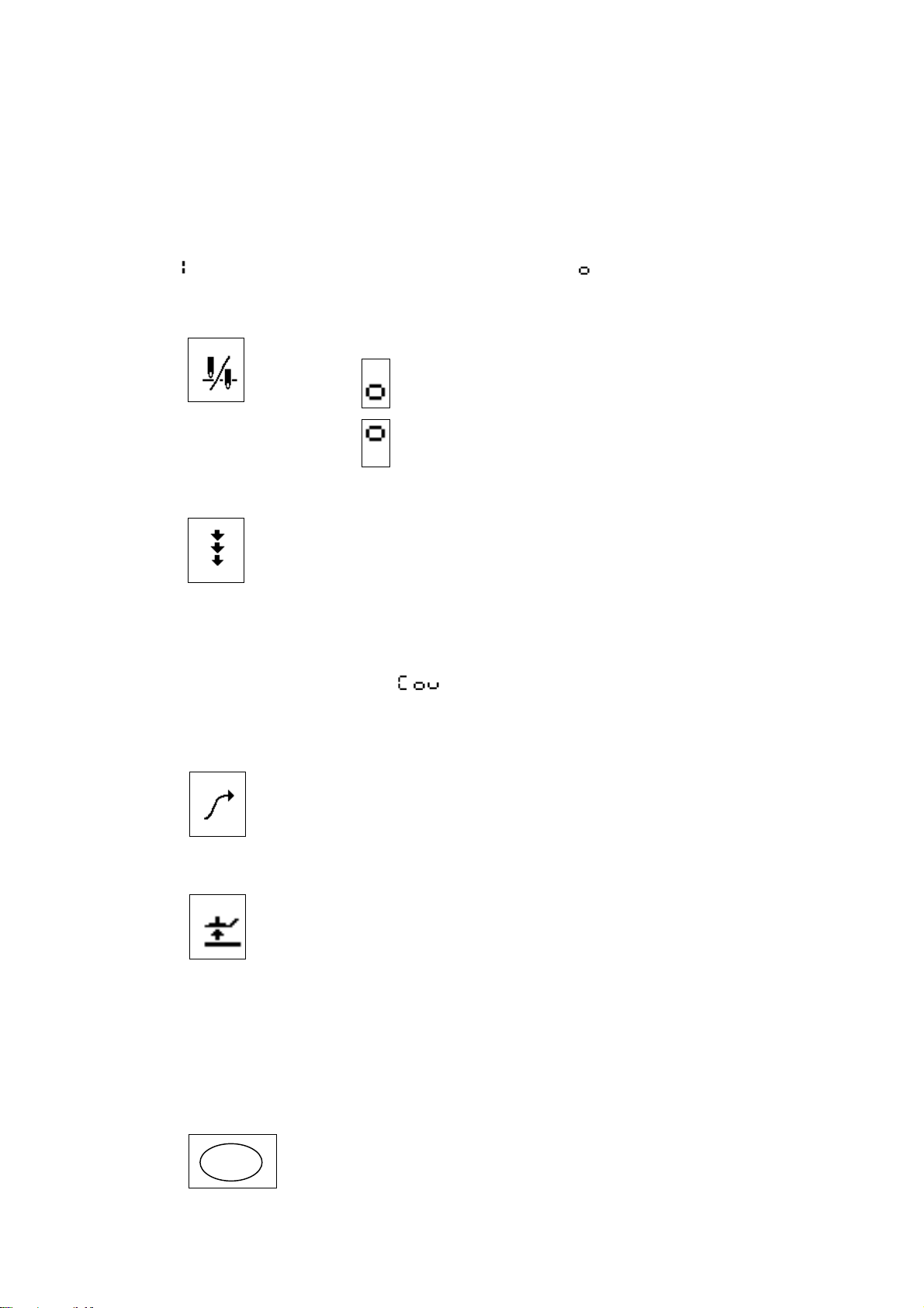
(1) Needle UP/DOWN key
The A [△] key can be used to switch the needle stop position to UP or DOWN.
When is displayed : OFF (needle stops in DOWN position when
treadle is at neutral)
When is displayed : ON (needle stops in UP position when treadle
is at neutral)
(2) Correction key
The B [△] key can be used to turn correction sewing ON or OFF.
Set to ON if you would like to use the actuator switch for correction sewing
when the sewing machine is stopped. Correction sewing (low speed) can
then be carried out. This cannot be used after thread trimming when the
needle stops in the UP position.
If the actuator switch is pressed while the sewing machine is operating,
reverse feed will be carried out.
Note: If using a covering sewing machine with the machine head type set to
B256 ("
trimming/wiping ON and OFF. When set to ON, top covering thread
trimming/wiping is enabled, and when set to OFF, it is disabled.
∗"), this key can be used to turn top covering thread
(3) Slow start key
The C [△] key can be used to turn the slow start ON or OFF.
Set to ON if you would like the slow start to be used at the sewing start (after
thread trimming and needle UP stop).
(The first two stitches are sewn at slow speed.)
(4) Presser lifter key
The D [△] key can be used to raise and lower the presser lifter (ON/OFF).
Set to ON if you would like the presser lifter to be raised when the sewing
machine stops. When set to ON, the presser foot is always raised when the
sewing machine is stopped. This includes when the power is first turned ON,
when the sewing machine stops in the needle DOWN position, after thread
trimming is completed and when the sewing machine stops in the needle UP
position.
∗ This function operates in the same way as the knee switch (shorting/
opening the 1-pin plug of the presser foot 6-pin connector).
Changing the panel display mode
(5) Using the function (FUNC) key
When the FUNC key is pressed, the LEDs are turned ON and OFF in the
FUNC
following sequence: Sewing speed LED ON, ABCD (tacking number) LED
ON, EF (fixed length number) LED ON, all LEDs OFF.
– 6 –
Page 9
(6) Sewing speed display mode
Press the FUNC key so that the sewing speed LED is ON.
The current setting value for the sewing speed appears in the "ABCD"
display.
The A [△] key can be used to set the thousands digit, and the B [△] key can
be used to set the hundreds digit.
(The setting range is within the inching speed setting and the maximum
sewing speed limit.)
(7) Backtack stitch number display mode
Press the FUNC key again to turn the sewing speed LED OFF and the
ABCD
ABCD LED ON. If the start tacking, end tacking or continuous tacking LED is
ON, the number of stitches set for that tacking will appear in the "ABCD"
display.
Press the A [△] key to set the number in the A column. Press the B [△] key
to set the number in the B column. Press the C [△] key to set the number in
the C column. Press the D [△] key to set the number in the D column. Each
column can be set to a number between 0 and 9. When 9 is reached and the
[△] key is pressed again, the setting returns to 0.
(8) Fixed length stitch number display mode
For patterns 2 to 4, press the FUNC key again to turn the ABCD LED OFF
EF
and the EF LED ON. The number of stitches set for F will appear in the AB
columns, and the number of stitches set for E will appear in the CD columns.
Backtack display mode and key operations
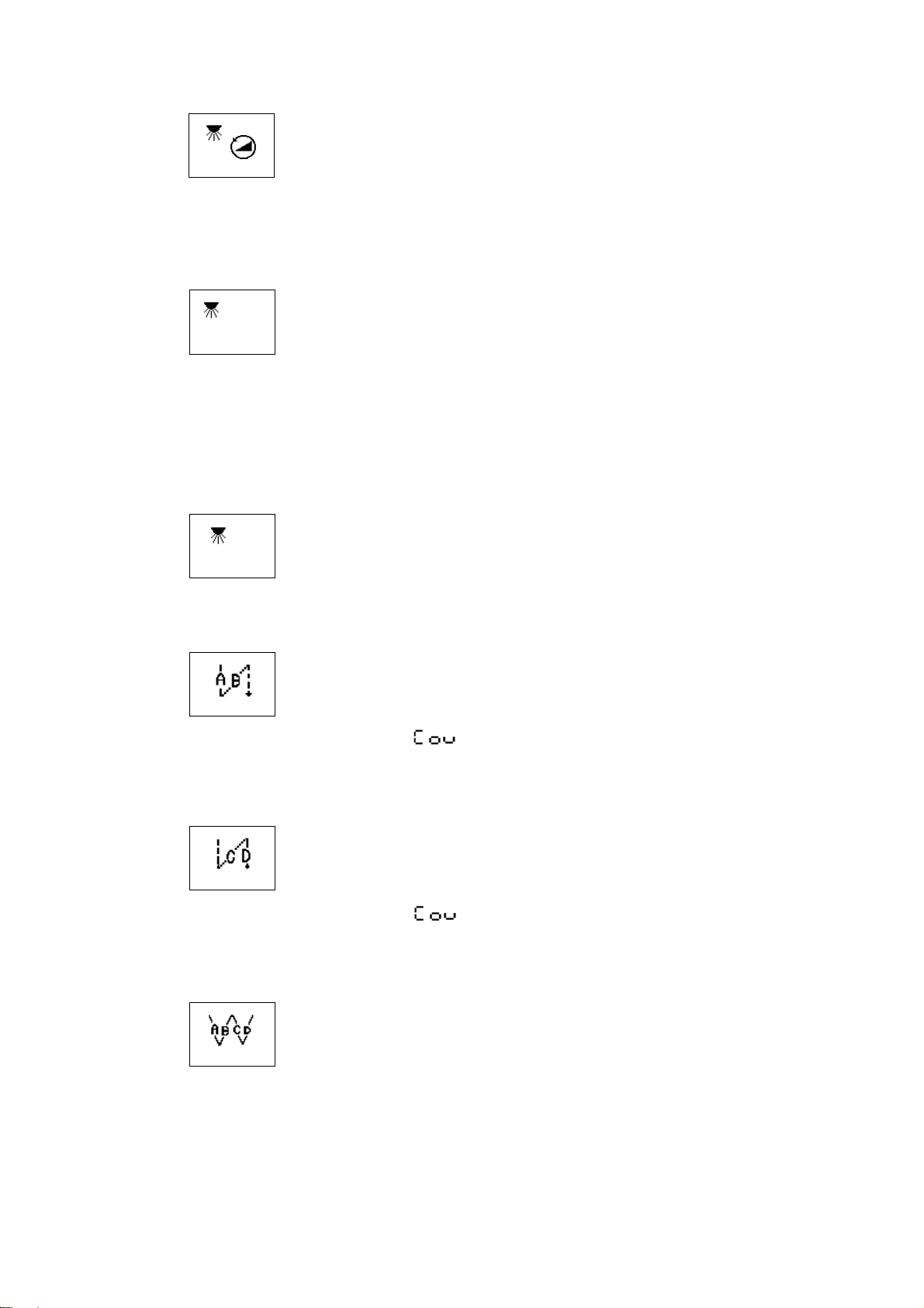
(9) Start tacking key
When the start tacking key is pressed, the LED turns ON. The number of
start tacking stitches which has been set (0 to 9) will appear in the AB
columns.
Note: If using a covering sewing machine with the machine head type set
to B256 ("
∗"), this key will turn start condense stitch sewing ON
and OFF. The number of start condense stitches which has been set
(0 to 99) will appear in the AB columns.
(10) End tacking key
When the end tacking key is pressed, the LED turns ON. The number of end
tacking stitches which has been set (0 to 9) will appear in the CD columns.
(End tacking can be canceled before it is completed.)
Note: If using a covering sewing machine with the machine head type set
to B256 ("
∗"), this key will turn end condense stitch sewing ON
and OFF. The number of end condense stitches which has been set
(0 to 99) will appear in the CD columns.
(11) Continuous tacking key
When the continuous tacking key is pressed, the LED turns ON. The number
of continuous tacking stitches which has been set (0 to 9) will appear in the
ABCD columns. After each cycle has been completed, the thread is trimmed
automatically.
∗ (9) to (11) are not available with the B776/SBL.
– 7 –
Page 10
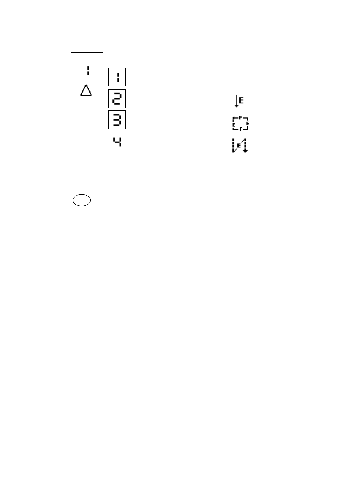
Pattern display mode and key operation
(12) Pattern setting and key operation
The sewing pattern can be set from 1 to 4. The pattern number increases by
1 each time the pattern key is pressed.
Manual mode
Fixed length sewing mode
Label attaching mode
Pleat sewing mode
∗ Patterns (2) to (4) are not available with the B776/SBL.
Accepting settings
(13) Using the SET key
This key is used to accept settings and to end the setting procedure in
SET
machine head setting mode, memory switch mode, parameter mode and
initialization mode.
It can also be used to accept settings and to end the setting procedure in
input/output setting mode and special mode.
– 8 –
Page 11
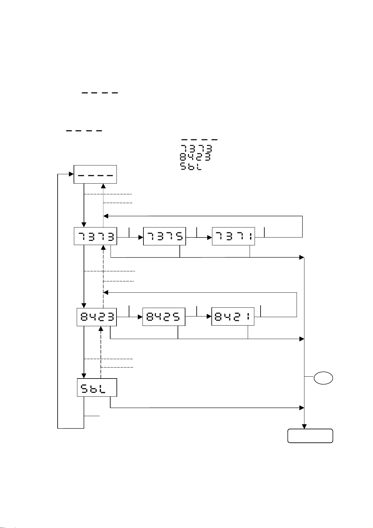
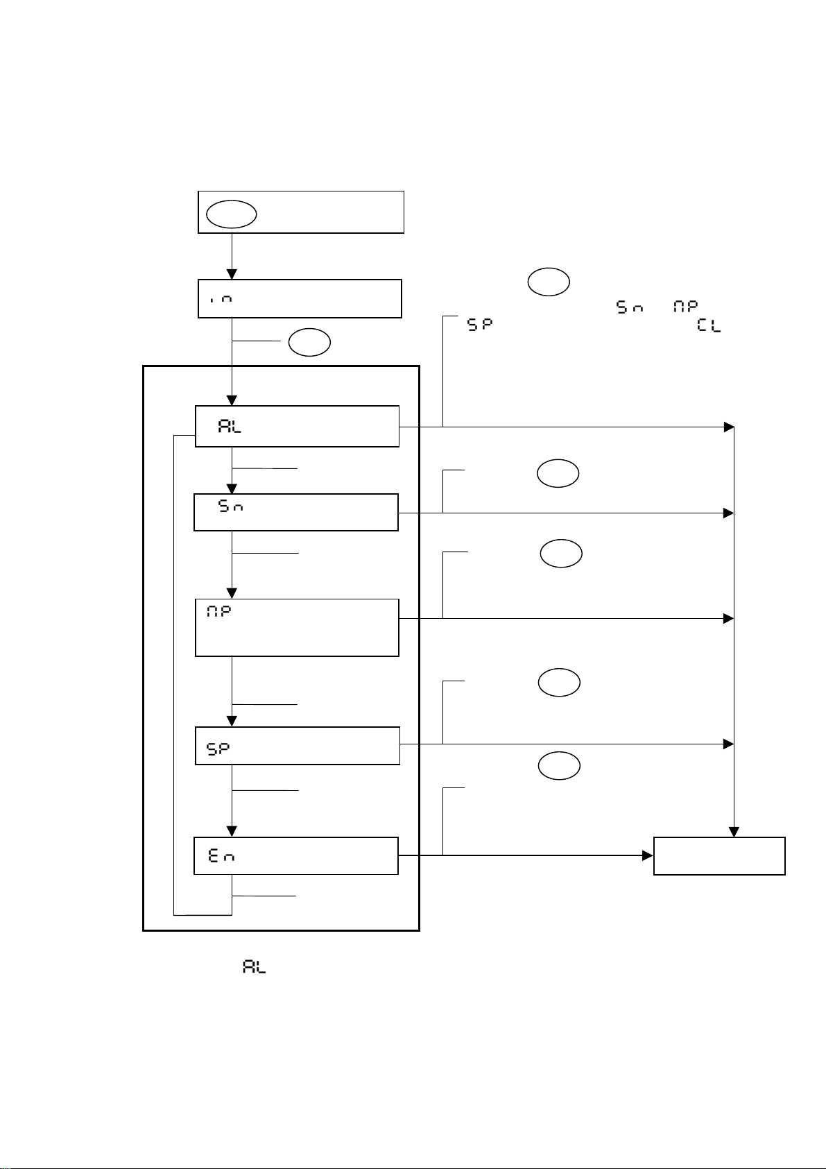
2. Using the machine head setting mode
This product is shipped with the general specifications, so the machine head model is not set.
Thus, the machine head model must be set during setup.
Check the sewing machine model, and set the head with the following procedures.
Turn the power switch ON.
Is the built-in panel's power lamp (green) ON?
Is "
The motor will not start even if the treadle is pressed in this state.
Call out and set the sewing machine model name in this state.
Setting the machine head
"
" flashing at the built-in panel's A, B, C, D digits?
" will be flashing.
Display No. "
Display No. "
Display No. "
Display No. "
" : Machine head type has not been set.
" : Machine head is DB2-B737-3.
" : Machine head is LT2-B842-3.
" : Machine head is an SBL overlock.
Press the B [△] key to show the next type.
Press the C [△] key to show the previous type.
D [△] key D [△] key D [△] key
B [△] key
C [△] key
D [△] key D [△] key D [△] key
B [△] key
C [△] key
B [△] key
Note) Set the machine head type in machine head setting mode.
Use the B [△] key to increment the setting, and the C [△] key to decrement the setting.
Press the D [△] key to set the sub-class.
Press the SET key to accept the setting. Machine head setting mode will then be
exited.
Refer to "Machine head setting mode list" for the machine head types.
Press the
SET
key to
complete the
setting.
Sewing mode
– 9 –
Page 12
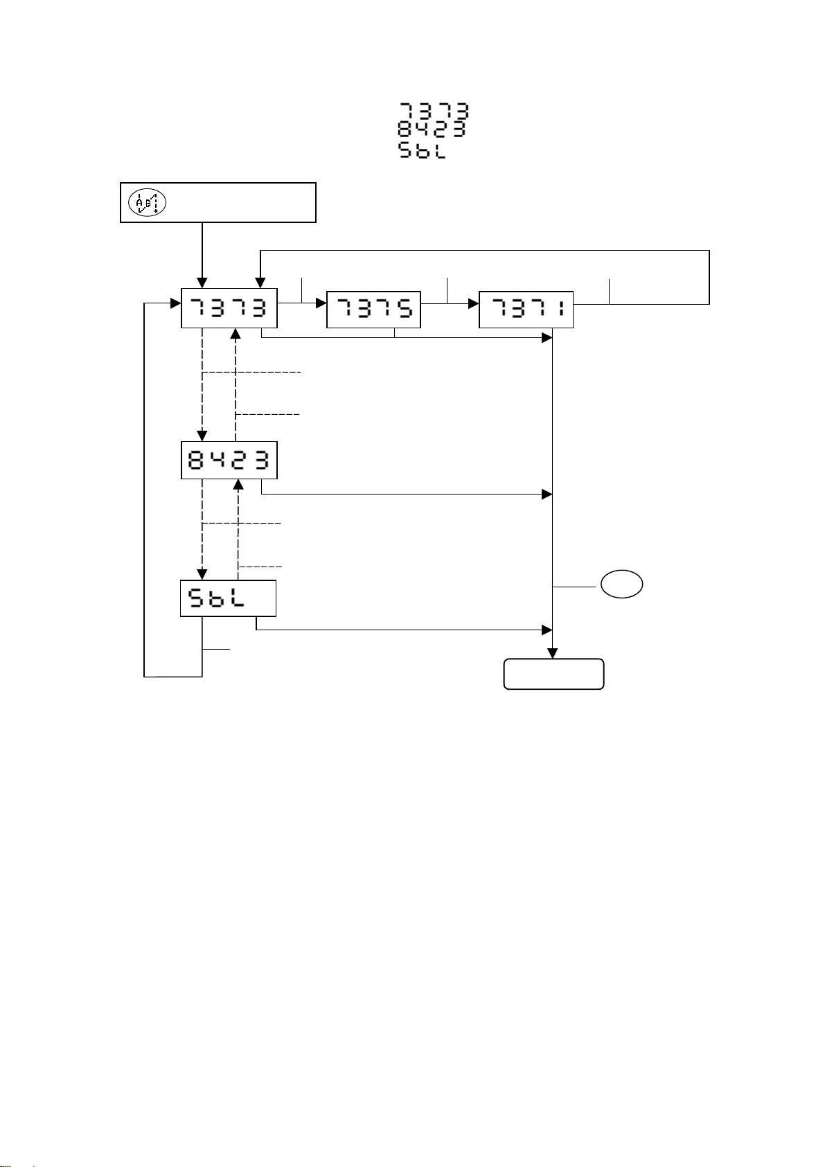
Checking, setting and changing the machine head
Display No. "
Display No. "
Display No. "
+ Power switch ON
D [△] key D [△] key D [△] key
B [△] key (Increment)
C [△] key (Decrement)
" : Machine head is DB2-B737-3.
" : Machine head is DB2-B842-3.
" : Machine head is an SBL overlock.
B [△] key
C [△] key
B [△] key
Sewing mode
Note) Set the machine head type in machine head setting mode.
Use the B [△] and C [△] keys to set the name, and use the D [△] key to select the
sub-class.
Press the SET key to accept the setting. Machine head setting mode will then be
exited.
∗ Refer to "Machine head setting mode list" on page 11 for the machine head types.
Press the
SET
key to
complete the
setting.
– 10 –
Page 13
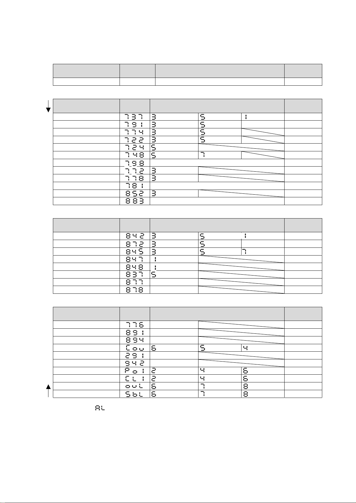
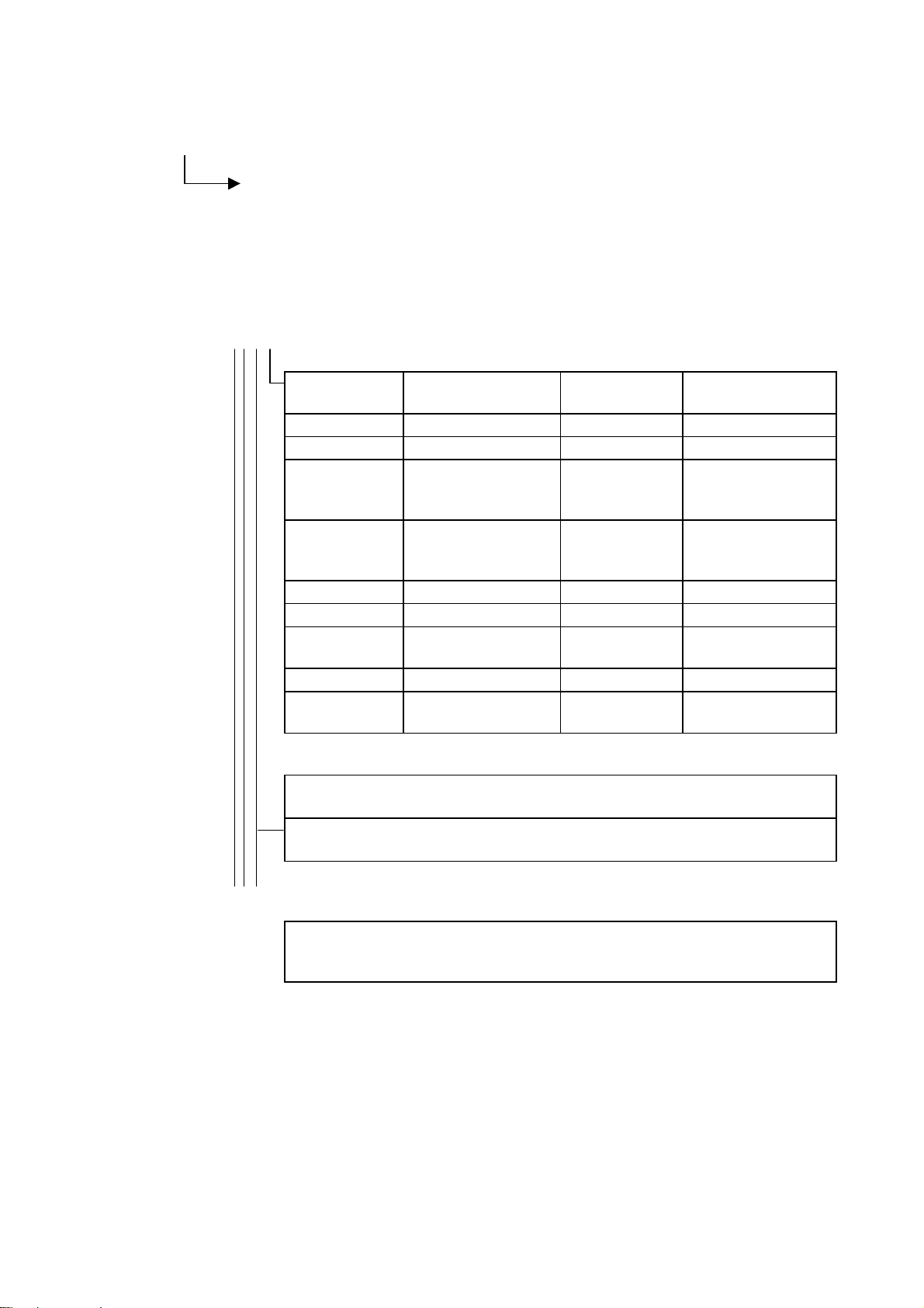
Machine head setting mode list
This table shows the machine head names, maximum sewing speeds and motor pulley diameters.
(1) Factory default setting (no machine head setting)
Machine head
No machine head setting – – – –
"ABC"
display
"D" display
Motor pulley
diameter
(2) Single needle
Machine head
B737/B201/B755 ・・・・4700rpm ・・・・ 3500rpm ・・・・ 4000rpm ø90/ø105
B791 ・・・・4500rpm ・・・・ 3500rpm ø90/ø105
B774 ・・・・4500rpm ・・・・ 3500rpm ø90/ø105
B722 ・・・・4700rpm ・・・・ 4000rpm ø90/ø105
B724 ・・・・4000rpm ø90
B748A ・・・・4000rpm ・・・・ 3000rpm ø90
B798/B728 None・・・ 2000rpm ø90
B772A ・・・・4700rpm ø90/ø105
B778A ・・・・4700rpm ø90/ø105
B781 None・・・ 4000rpm ø90
B852/B853/B854 ・・・・4500rpm ø90
B883 None・・・ 850rpm ø90
"ABC"
display
"D" display
Motor pulley
diameter
(3) Twin needle
Machine head
B842 ・・・・4000rpm ・・・・ 3500rpm ・・・・ 4000rpm ø90
B872 ・・・・3000rpm ・・・・ 3000rpm ø90
B845/B875 ・・・・3000rpm ・・・・ 3000rpm ・・・・ 3000rpm ø90
B847 ・・・・4000rpm ø90
B848 ・・・・3000rpm ø90
B837 ・・・・3000rpm ø90
B877 None・・・ 3000rpm ø90
B878 None・・・ 2500rpm ø90
"ABC"
display
"D" display
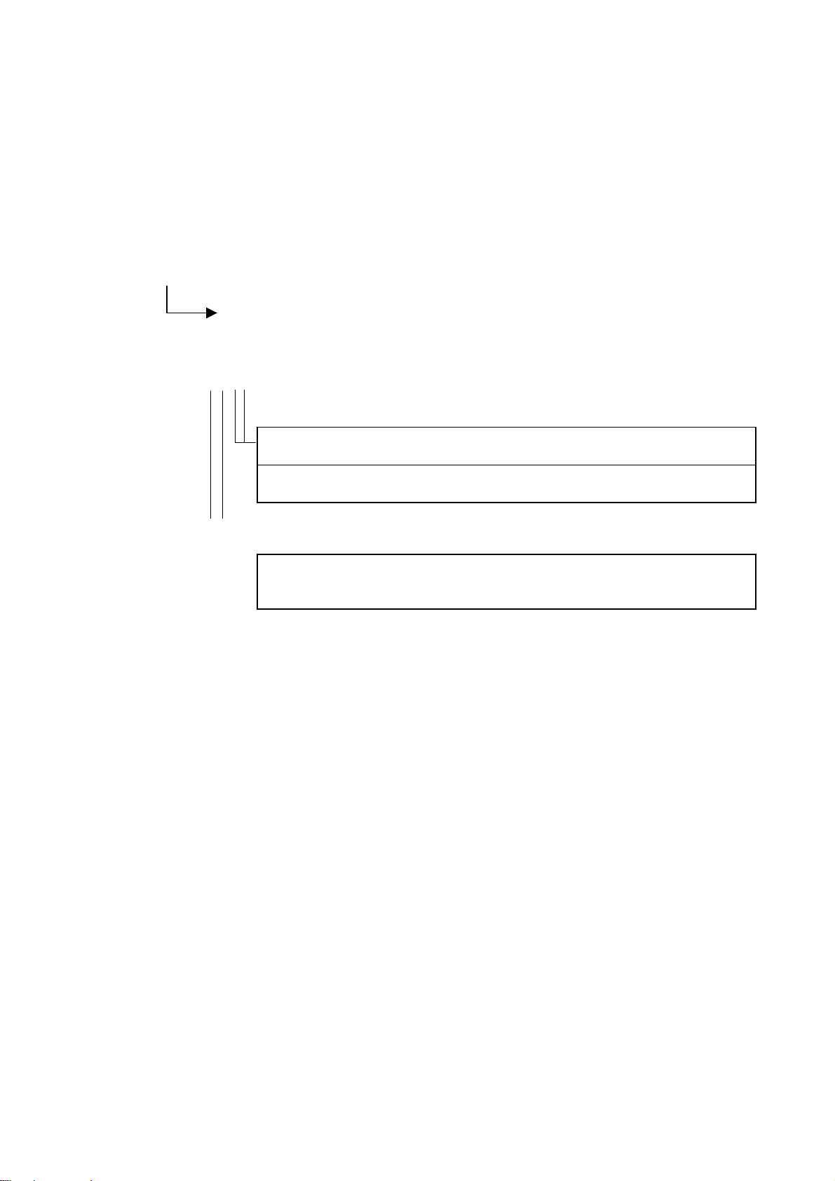
(4) Special, heavy material, chain stitch, overlock
Machine head
B776 None・・・ 4500rpm ø90
B891/B892 None・・・ 3500rpm ø80
B894 None・・・ 3500rpm ø80
B256/B276 ・・・・6000rpm ・・・・ 5000rpm ・・・・ 4500rpm ø105
B291 None・・・ 4500rpm ø90
B942 None・・・ 4000rpm ø90
P73/P81 ・・・・2200rpm ・・・・ 2400rpm ・・・・ 2600rpm ø90
C51 ・・・・2200rpm ・・・・ 2400rpm ・・・・ 2600rpm ø90
Overlock ・・・・6000rpm ・・・・ 7000rpm ・・・・ 8000rpm ø105
SBL ・・・・6500rpm ・・・・ 7000rpm ・・・・ 8000rpm ø105
"ABC"
display
"D" display
Motor pulley
diameter
Motor pulley
diameter
Note 1) Even if " " is used to clear all settings in initialization mode, machine head setting mode will retain
the machine head setting which was active before all settings were cleared.
2) Refer to the Instruction Manual for checking methods after machine head setting mode is completed.
3) The machine head type displayed moves down the list each time the B [△] key is pressed.
4) The machine head type displayed moves up the list each time the C [△] key is pressed.
5) The motor pulley diameter shown is the outer diameter. Attach the appropriate pulley depending on the
machine head type.
DIP switch 1-2 on the control PCB is used to select the pulley size. Set DIP switch 1-2 to match the size
of the pulley installed.
– 11 –
Page 14
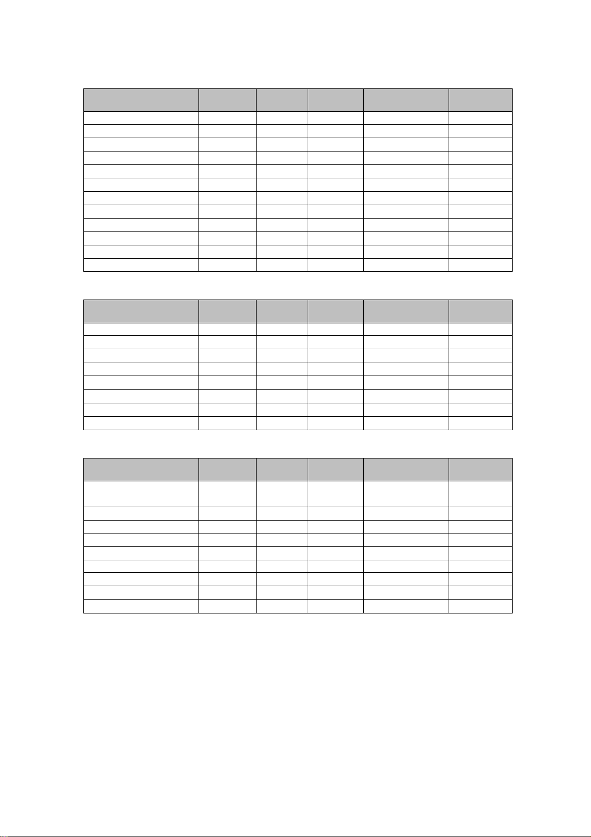
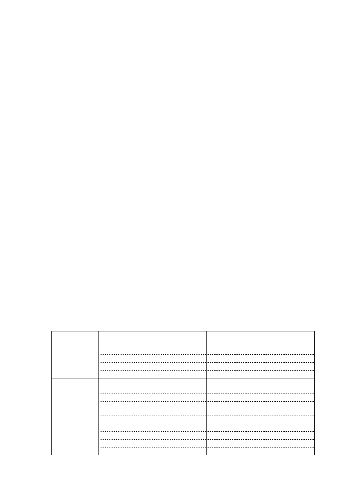
Other machine sewing speeds
(1) Single needle
Machine head
B737/B201/B755 215rpm 215rpm 215rpm 1800rpm 1700rpm
B791
B774
B722
B724
B748
B798
B772A
B778A
B781
B852/B853/B854
B883 250rpm 170rpm 250rpm 250rpm 500rpm
Inching
speed
↓↓↓ ↓ ↓
↓↓↓ ↓ ↓
↓↓↓ ↓ ↓
↓↓
↓↓
↓↓↓
↓↓↓
↓↓↓ ↓ ↓
↓↓↓ ↓ ↓
↓
Thread
trimming
185rpm
Slow Start/end tacking
500rpm 1600rpm
215rpm 1200rpm
1000rpm
1800rpm
↓
1200rpm
Improved
stopping
↓
↓
↓
↓
↓
(2) Twin needle
Machine head
B842 250rpm 185rpm 250rpm 1000rpm 1500rpm
B872
B845/B875
B847
B848
B837
B877
B878
Inching
speed
↓↓↓ ↓ ↓
↓↓↓ ↓ ↓
↓↓↓ ↓ ↓
↓↓↓ ↓ ↓
↓↓↓ ↓ ↓
↓↓↓
↓↓↓ ↓ ↓
Thread
trimming
Slow Start/end tacking
800rpm
Improved
stopping
↓
(3) Special, heavy material, chain stitch, overlock
Machine head
B776 215rpm 215rpm 800rpm 1800rpm 1700rpm
B891/B892 250rpm 185rpm 250rpm 800rpm 1500rpm
B894
B256/B276 215rpm 215rpm 215rpm 1800rpm 1700rpm
B291
B942
P73/P81 250rpm 185rpm 250rpm 1000rpm 1500rpm
C51
Overlock 215rpm 215rpm 215rpm 1800rpm
SBL
Inching
speed
↓↓↓ ↓ ↓
↓↓↓ ↓ ↓
↓↓↓ ↓ ↓
↓↓↓ ↓ ↓
↓↓
Thread
trimming
Slow Start/end tacking
1500rpm
↓↓
Improved
stopping
↓
– 12 –
Page 15
3. Initialization mode
Memory data is stored in the EEPROM. If this data is changed by mistake, you can re-initialize
the data in initialization
Setting method
FUNC
+ Power switch ON
[ ] Initialization mode menu
key ON
SET
Initialization menu
[ ]・・・ Clear all settings
B [△]
[ ]・・・・Initialize stitch
number data
B [△]
[ ] ・・・ Initialize memory
switch and
parameters settings
Press the key to start initializing, and
SET
carry out each step for [ ] + [ ] +
[ ]. When each step is finished, [ ] will
appear. The display is cleared when you go
back to sewing mode.
Press the key to initialize.
Press the key to initialize.
SET
SET
Data returns to the data set in
machine head setting mode.
[ ]・・・ Initialize speed data
[ ]・・・ Exit mode
Note) Even if [
mode will retain the model set before all clear was executed.
B [△]
Press the key to initialize.
Data returns to the data set in
SET
machine head setting mode.
B [△]
Press the key to quit the
initialization mode.
SET
The sewing mode will be entered
without the initialization taking place.
Sewing mode
B [△]
] all clear is executed in the initialization mode, the machine head setting
– 13 –
Page 16
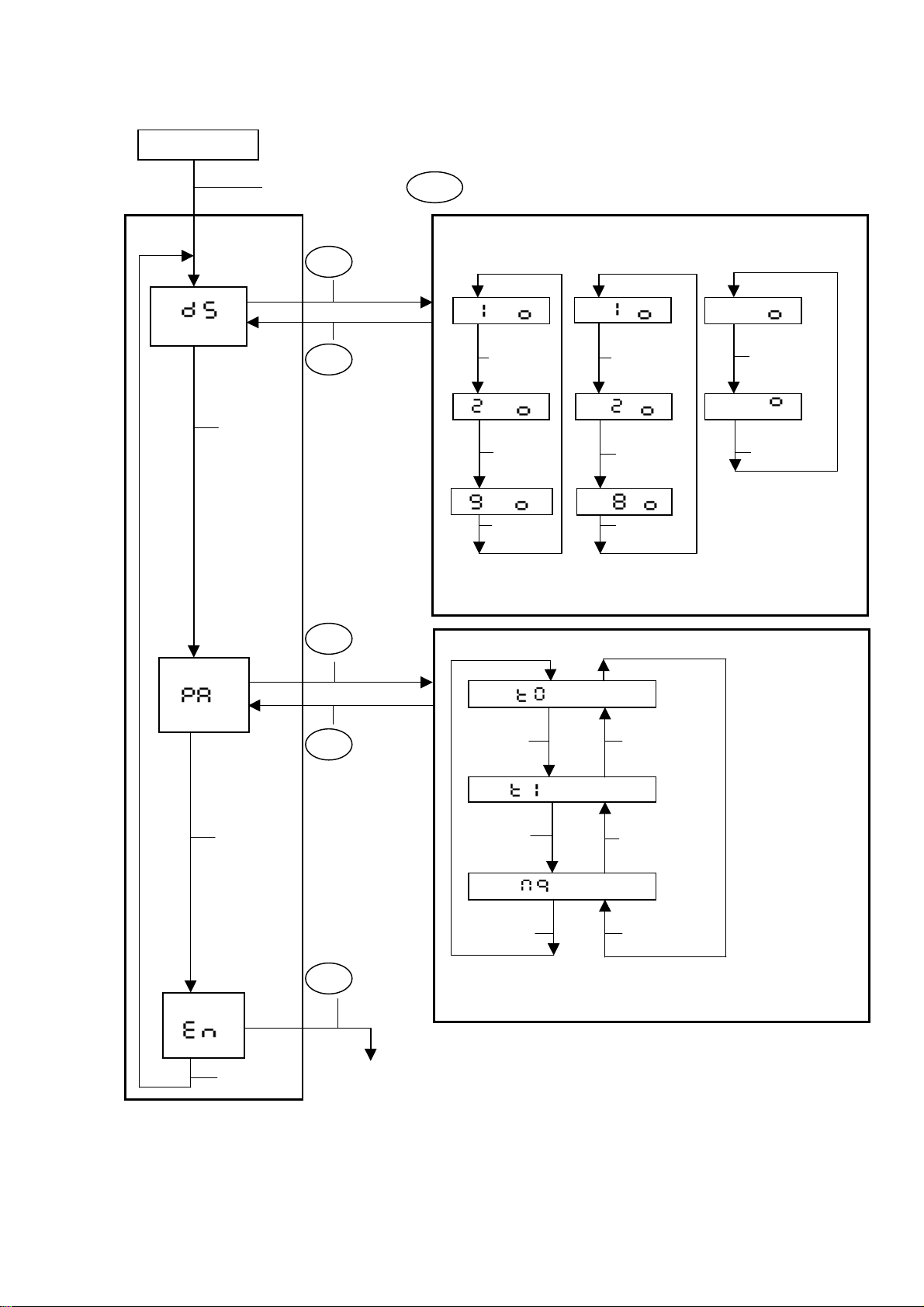
4. Memory switch setting mode and parameter setting mode
When stopped
Setting
mode 1
[ ]
While pressing the key, turn the A [△] key ON.
FUNC
Memory switch setting mode
key ON
SET
[ ∗ - ]
key ON
SET
A [△]
for 2 seconds
B [△]
or more to
finish
[ ∗ - ] [∗ - ]
A [△]
[ ∗ - ] [∗ - ]
A [△]
Use the A [△] and B [△] keys to set the memory
switch number.
Use the D [△] key to set to ON or OFF.
[∗ - ]
B [△]
B [△]
B [△]
[∗ ∗ - ]
D [△]
[∗ ∗ - ]
D [△]
[ ]
[ ]
B [△]
B [△]
key ON
SET
SET
key ON
Parameter setting mode
for 2 seconds
or more to
finish
SET
key ON
Use the A [△] and B [△] keys to set the parameter
number.
Use the C [△] and D [△] keys to set to ON or OFF.
Setting mode 1 exited
[ ∗ ∗ ]
A [△]
B [△]
[ ∗ ∗ ]
A [△]
B [△]
[ ∗ ∗ ]
A [△]B [△]
Note) Parameter setting mode cannot be entered until memory switch [01] is set to ON.
∗ Refer to page 16 to 22 for the Memory switch list.
∗ Refer to page 23 to 29 for the Parameter list.
– 14 –
Page 17

5. Speed setting mode, I/O check mode and ROM ver. mode setting
When stopped
Setting
mode 2
[ ]
B [△]
While pressing the
FUNC
key, turn the B [△]
key ON.
key ON
SET
key ON
SET
for 2 seconds
or more to
finish
∗ Refer to page 29 for the List of speed setting modes.
∗ Refer to pages 30 to 32 for the List of input/output check modes.
Speed setting mode
Speed symbol display
[ ]
A [△]
FUNC
SET
Setting value display
key ON
(Inching speed)
[ ]
key ON
Use [△] key
to change
A [△]
A [△]
[ ]
[ ]
B [△]
B [△]
FUNC
SET
FUNC
SET
key ON
key ON
key ON
key ON
(Thread trimming
speed)
[ ]
Use [△] key
to change
(Improved stoping
speed)
[ ]
Use [△] key
to change
B [△]
Use the A [△] and B [△] keys to select the speed for setting.
Use the A to D [△] keys to set the speed.
[ ]
[ ]
B [△]
SET
SET
SET
SET
key ON
key ON
key ON
key ON
I/O check mode
[ . ∗ ∗ ]
FUNC
[ ∗ ∗ ]
FUNC
[ . ∗ ∗ ]
FUNC
[ ∗ ∗. ∗ ∗ ]
Input signal check mode
∗ Use the A [△] and B [△] keys to select the
signal.
∗ CD columns show if signal is OFF or ON.
key ON
Analog voltage check mode
∗ Use the B [△] key to select the analog signal
number.
∗ Use the A [△] key to change the display mode.
∗ CD columns shows voltage value.
key ON
Output check mode
∗ Use the A [△] and B [△] keys to select the
signal.
∗ Use the D [△] key to set to ON or OFF.
key ON
ROM version display mode
∗ Ver. ∗ ∗. ∗ ∗
B [△]
SET
key ON
[ ]
B [△]
Setting mode 2 exited
– 15 –
Page 18

9. Memory switch list
Display
No.
SW Item & Contents
ON Parameter setting change enabled (Parameter setting mode can be entered)
OFF
ON No interlock during thread trimming
OFF
ON Momentary drop or failure of power supply check valid
OFF
ON SBT speed and EBT speed (No relation with high speed setting)
OFF
ON (Not used)
OFF
ON No penetration force UP operation
OFF
ON (Not used)
OFF
ON (Not used)
OFF
ON
OFF
ON
OFF
ON Presser lifter rise after neutral stop when the treadle is neutral stop.
OFF
ON (Not used)
OFF
ON Normally is deceleration
OFF
ON No over time [ ] function
OFF
ON
OFF
ON
OFF
Parameter setting change disabled (Parameter setting mode cannot be entered)
No interlock during thread trimming (Invalid)
Momentary drop or failure of power supply check (Invalid)
SBT speed and EBT speed (No more than of high speed setting)
∗ Normally OFF
Penetration force UP operation (Set time with parameters [Mi] and [MJ])
∗ Normally OFF
∗ Normally OFF
Thread trimming validity setting enabled (F-operation panel is connected)
∗ [ ] ON enabled, [ ] OFF not enabled
Thread trimming validity setting disabled (Treadle repression always includes
thread trimming)
Presser lifter rise after thread trimming when the treadle is neutral
(In the case of DIP switch 1-1 ON)
Presser lifter descent after thread trimming when the treadle is neutral
(In the case of DIP switch 1-1 OFF)
Presser lifter descent after thread trimming when the treadle is neutral
(In the case of DIP switch 1-1 ON)
Presser lifter rise after thread trimming when the treadle is neutral
(In the case of DIP switch 1-1 OFF)
Presser lifter descent after neutral stop when the treadle is neutral stop.
∗ Normally OFF
Quick stop is deceleration
Over time [ ] function (By a continuous 3 minutes stop)
[ ] OFF, Actuator switch = Half stitch correction switch
[ ] ON, Actuator switch = 1 stitch correction switch
[ ] OFF, Actuator switch = Normally switch
[ ] ON, Actuator switch = 1 stitch correction switch
[ ] OFF, Actuator switch = Reverse stitch correction switch
[ ] ON, Actuator switch = 1 stitch correction switch
[ ] OFF, Actuator switch = Normally switch
[ ] ON, Actuator switch = 1 stitch correction switch
∗ The shaded fields indicate the default values.
– 16 –
Page 19

Display
No.
SW Item & Contents
ON Start tacking double (A, B, A, B)
OFF
ON End tacking double (C, D, C, D)
OFF
ON No. of start tacking stitches +10 (A + 10, B + 10)
OFF
ON No. of end tacking stitches +10 (C + 10, D + 10)
OFF
ON
OFF
ON No slow down to low speed on starting of end tacking
OFF
ON Continuous tacking A, B [stitches] × D [Number of time]
OFF
ON No. of continuous tacking stitches +10 stitches
OFF
ON
OFF
ON
OFF
ON Call fixed stitches when pleats sewing will be used.
OFF
ON No LED call when continuous tacking [ ] is canceled.
OFF
ON
OFF
ON Holding time control of presser lifter is not OFF by timer
OFF
ON
OFF
ON OFF ON 1ms 5ms
OFF
Start tacking single (A, B)
End tacking single (C, D)
Normally (A, B)
Normally (C, D)
Root stitching (Stop with reverse ON after start tacking)
∗ Active, when [ ] is ON and memory switch 31 is set OFF.
Stop with reverse OFF after start tacking
∗ Active, when memory switch 68 is set OFF.
Slow down to low speed on starting of end tacking
After end tacking goes into acceleration
Continuous tacking A, B, C, D
Normally
Enable to stop during start tacking, speed is variable with treadle. (start tacking
speed at maximum treadle repression)
Not enable to stop during start tacking, speed is keep speed by treadle. (start
tacking speed)
F-20, 40 No. of tacking stitches change enabled
∗ Tacking stitches are ABCD set No.
F-20, 40 No. of tacking stitches change disabled.
∗ No. of stitches is fixed with 4, when switch F-20 [ ], F-40 [ ] ON.
∗ No. of AB tacking stitches are sewn when switch F-40 of [ ], [ ] ON.
No call fixed stitches when pleats sewing will be used.
LED call when continuous tacking [ ] is canceled.
∗ Set [ ], [ ], [ ], [ ], [ ] is call back.
When [ ] switch is OFF.
Soft down of presser lifter is timer mode
(OFF time is [ ], ON time is [ ])
Soft down of presser lifter is analog mode
(ON time is [ ] of setting timer)
Holding time control of presser lifter is not ON by timer
(ON time is [ ] of setting timer)
Chopping duty of presser lifter setting
37 38 ON OFF Transistor controlling
OFF OFF 2.5ms 2.5ms
ON OFF 1ms 1ms
ON ON 1ms 1ms
Upper and lower transistor
ON/OFF at a same time
Upper transistor keep ON,
lower transistor ON/OFF.
– 17 –
Page 20

Display
No.
SW Item & Contents
ON Lifting of presser lifter invalid at treadle repressed backwards to 1st step
OFF
ON
OFF
ON Chain stitch thread trimming (at needle UP position, motor stopped)
OFF
ON
OFF
ON Standing work delay start invalid
OFF
ON
OFF
ON
OFF
ON Prohibit to rise of presser lifter with trimming pedal during standing work
OFF
ON Active correction by actuator switch after trimming
OFF
ON (Not used)
OFF
ON (Not used)
OFF
ON (Not used)
OFF
ON
OFF
ON
OFF
ON
OFF
Normally
Prohibit to thread trimming by treadle repressed backwards ∗ For overlock, etc.
Normally
Lockstitch thread trimming operation
High-speed pedal during standing work is only high speed. (no inching speed and
variable speed area)
Standing work pedal for variable speed
Standing work delay start valid
Emergency stop by presser pedal disabled during standing work (during
automatic stitching)
Emergency stop by presser pedal enabled during standing work (during
automatic stitching)
Emergency stop by high-speed pedal disabled during standing work (during
automatic stitching)
Emergency stop by high-speed pedal enabled during standing work (during
automatic stitching)
Normally
Inactive correction by actuator switch after trimming
∗ Normally OFF
∗ Normally OFF
∗ Normally OFF
After presser foot lowers with treadle repressed forward to 1st step, presser foot
does not lift when treadle is pressed to neutral position.
After repressing treadle backward, presser foot lowers when treadle is pressed to
neutral position
∗ When DIP switch 1-1 is ON (when memory switch [12] or [13] is set to ON)
∗ Repressing to forward 1st step is valid only when DIP switch 1-4 is set to ON
After presser foot lowers with treadle repressed forward to 1st step, presser foot
lifts when treadle is pressed to neutral position.
After repressing treadle backward, presser foot does not lift when treadle is
pressed to neutral position
∗ When DIP switch 1-1 is ON (when memory switch [12] or [13] is set to ON)
∗ Repressing to forward 1st step is valid only when DIP switch 1-4 is set to ON
After thread trimming, pressing treadle forward ON stroke is not changed after
pressing treadle backward.
After thread trimming, pressing treadle forward ON stroke is changed after
pressing treadle backward.
∗ Reduction of incorrect forward treadle repressing operation caused by rebound
of treadle from backward repressing
Presser foot does not lower when treadle is pressed forward 1st step.
(When DIP switch 1-4 is ON)
Presser foot lowers when treadle is pressed forward 1st step.
(When DIP switch 1-4 is ON)
– 18 –
Page 21

Display
No.
SW Item & Contents
ON
OFF
ON Reverse rotation needle UP operation enabled
OFF
ON
OFF
ON
OFF
ON
OFF
ON (Not used)
OFF
ON
OFF
ON
OFF
ON
OFF
ON (Not used)
OFF
ON (Not used)
OFF
ON
OFF
ON (Not used)
OFF
Reverse solenoid operation enabled when stopped
∗ Do not set to ON except in B891 group)
Reverse solenoid operation disabled when stopped
Reverse rotation needle UP operation disabled
When reverse rotation needle UP operation is enabled, raise needle and then
wipe.
∗ When memory switch [61] is ON
When reverse rotation needle UP operation is enabled, wipe and then raise
needle.
∗ When memory switch [61] is ON
Timer operates thread trimming
∗ When B852, B891/B892, B894, B256/B276 are set
∗ When B852 is set, timer time is set with parameter [ ].
∗ When B891/B892, B894, B256/B276 are set, set with parameter [ ]
Thread trimming is turned ON with needle DOWN signal, and OFF with needle
UP signal
When needle is raised and stop with [ ] key and actuator switch, needle stops
at reverse rotation needle UP position
∗ When memory switch [61] is ON
When needle is raised and stop with [ ] key and actuator switch, needle stops
at needle UP position
∗ Normally OFF
When reverse needle UP operation is enabled, presser turns ON before needle
UP.
∗ When memory switch [62] is set to OFF, presser turns ON after thread wiping
When reverse needle UP operation is enabled, presser turns ON after needle UP.
Alternating presser foot movement is determined by number of stitches
Set number of stitches with parameter [ ].
Only when alternating presser foot movement is set.
Alternating presser foot movement change is not determined by number of
stitches
Sewing machine stops temporarily when automatic tacking reverse solenoid is
changed over.
∗ Machine can stop when switching to reverse of automatic tacking so that stitch
length of tacking will be same.
Parameter [ ]: stop time can be set (initial: 100ms)
Parameter [ ]: temporary stop position can be set
Sewing machine does not stop temporarily when automatic tacking reverse
solenoid is changed over
∗ Normally OFF
∗ Normally OFF
Air saving enabled (Set number of stitches with parameter [C1])
∗ For SBL air output
Air saving disabled
∗ Normally OFF
∗ For B891 group
– 19 –
Page 22

Display
No.
SW Item & Contents
ON
OFF
ON (Not used)
OFF
ON (Not used)
OFF
ON (Not used)
OFF
ON
OFF
ON
OFF
ON
OFF
ON
OFF
ON
OFF
ON Servo lock timer OFF operation disabled
OFF
ON
OFF
ON Servo lock enabled
OFF
ON Bobbin thread counter function available
OFF
ON Automatically stop after bobbin counter counts set number of stitches
OFF
ON
OFF
ON
OFF
Bobbin thread trimming signal ON twice ∗ For B256/B276
∗ Set time with parameters [ ] and [ ]
Bobbin thread trimming signal ON once
∗ Normally OFF
∗ Normally OFF
∗ Normally OFF
Status of alternating presser foot movement change LED is memorized.
∗ For B891 group
Status of alternating presser foot movement change LED is not memorized.
Status of pitch dial switch LED is memorized. ∗ For B891 group
Status of pitch dial switch LED is not memorized.
Presser foot rise by treadle is always active.
∗ Only when DIP switch 1-1 is set to OFF
Presser foot rise by treadle is not active after use of knee switch (presser lifter
switch).
∗ Only when DIP switch 1-1 is set to OFF
Inching speed < Thread trimming speed
∗ Inching speed can be set to slower than thread trimming speed to facilitate 1
stitch sewing.
Inching speed ≥ Thread trimming speed
Speed of end tacking = Speed of start tacking
∗ Setting speed of end tacking to same as start tacking
Speed of end tacking = Speed of end tacking
Servo lock timer OFF operation enabled
Brake force increases with presser UP/DOWN signal
∗ When memory switch [88] is set to ON
Brake force does not increase with presser UP/DOWN signal
∗ When memory switch [88] is set to ON
Servo lock disabled
Bobbin thread counter function not available
Do not automatically stop after bobbin counter counts set number of stitches
∗ Treadle operation prohibited after treadle stopped at neutral position
Treadle operation valid after standing work (during simultaneous operation,
standing work has priority)
Treadle operation invalid after standing work
Stitch change operation according to fabric end sensor valid
∗ For B891 group
Stitch change operation according to fabric end sensor invalid
∗ For B891 group
– 20 –
Page 23

Display
No.
SW Item & Contents
Wrapper open/close operation = alternating operation ∗ For B776
ON
OFF
ON Presser soft UP enabled
OFF
ON (Not used)
OFF
ON (Not used)
OFF
Alternating presser foot movement change operation = alternating operation
Ruler open/close operation = alternating operation ∗ For B256/B276
Wrapper open/close operation = momentary operation ∗ For B776
Alternating presser foot movement change operation = momentary operation
Ruler open/close operation = momentary operation ∗ For B256/B276
Presser soft UP disabled
Normally OFF
Normally OFF
∗ For B891 group
∗ For B891 group
– 21 –
Page 24

Memory switch default list
The following numbers are set to ON when the machine head is set. All others are set to OFF.
Display
No.
Head setting turned ON Function
[ ] OFF, Actuator switch = Half stitch correction
C51, P73/P81
All
B776, B891/B892, B894
B776, B256/B276
B291, B942, Overlock, SBL
B256/B276
B891/B892, B894
B852
B891/B892, B894
B256/B276
B877, B878
[ ] ON, Actuator switch = 1 stitch correction switch
F-20, 40 No. of tacking stitches change enabled
∗ Tacking stitches are ABCD set No.
Holding time control of presser lifter is not OFF by
timer
Lifting of presser lifter invalid at treadle repressed
backwards to 1st step
Prohibit to thread trimming by treadle repressed
backwards
Chain stitch thread trimming (at needle UP position,
motor stopped)
After stopping, reverse solenoid operation possible
with actuator switch
Thread trimmed with timer operation from needle
DOWN signal
Bobbin thread trimmed with timer operation at needle
UP stop position
Sewing machine stops temporarily when automatic
tacking reverse rotation is changed over
switch
↓
SBL Air saving enabled
B291, B942, Overlock, SBL Presser foot rise by treadle is always active.
B891/B892, B894 Servo lock enabled
B776 Wrapper open/close operation = alternating operation
B891/B892, B894
B256/B276 Ruler open/close operation = alternating operation
Alternating presser foot movement change operation =
alternating operation
– 22 –
Page 25

10. Parameter list
Display
No.
Initial data
02
(20ms)
05
(50ms)
05
(50ms)
30
(300ms)
60
(3 min)
15
(150ms)
00
(0ms)
00
(0ms)
00
(0ms)
00
(0ms)
07
(70ms)
07
(70ms)
10
(100ms)
24
(pulse)
24
(pulse)
24
(pulse)
24
(pulse)
(Note) The default data is the value set in B737 with the machine head setting.
Data setting
range
00 to 99 (X10)
(0 to 990ms)
00 to 99 (X10)
(0 to 990ms)
00 to 99 (X10)
(0 to 990ms)
00 to 99 (X10)
(0 to 990ms)
00 to 30 (X1)
(0 to 30 sec)
31 to 96 (X5)
(35 sec to 6 min)
00 to 99 (X10)
(0 to 990ms)
10 to 99 (X2)
(0 to 198ms)
00 to 30 (X10)
(0 to 300ms)
00 to 99 (X2)
(0 to 198ms)
00 to 99 (X2)
(0 to 198ms)
01 to 990 (X10)
(10 to 990ms)
01 to 990 (X10)
(10 to 990ms)
01 to 990 (X10)
(10 to 990ms)
00 to 47
(pulse)
00 to 47
(pulse)
00 to 47
(pulse)
00 to 47
(pulse)
Thread wiper ON delay time
Needle thread, Covering thread trimmer/wiper ON delay
time
∗ When B256/B276 is set
Thread wiper ON time
Needle thread, Covering thread trimmer/wiper ON delay
time
∗ When B256/B276 is set
Wiper OFF to presser lifting ON delay time
Bobbin thread trimmer OFF to presser lifting ON delay
time
∗ For needle thread, Covering thread trimmer/wiper,
setting + 90ms
∗ When B256/B276 is set
Presser lifter full-ON time
Holding time of presser lifter
00 : Does not turn OFF automatically
01 to 30: 1 to 30 sec (Set in one second increments)
31 to 96 : 35 sec to 6 min (Set in five seconds increments)
Delay time from presser lifter is lowered to motor start.
Presser UP signal OFF time (soft down)
∗ Valid only when memory switch [35] is set to ON
Presser UP signal ON time (soft down)
Presser signal ON time at presser soft UP
∗ When memory switch [96] is set to ON
Presser signal OFF time at presser soft UP
∗ When memory switch [96] is set to ON
Presser UP signal ON time at presser foot lifting
∗ For latch type presser lifter device when SBL is set
Presser signal ON time at presser foot lowering
∗ For latch type presser lifter device when SBL is set
Presser operation prohibit time
∗ For latch type presser lifter when SBL is set
Start tacking A → B reverse solenoid ON timing
(The larger the value is, the larger the timing delays.)
(The smaller the value is, the faster the timing becomes.)
Start tacking B end reverse solenoid OFF timing
(The larger the value is, the larger the timing delays.)
(The smaller the value is, the faster the timing becomes.)
End tacking C → D reverse solenoid ON timing
(The larger the value is, the larger the timing delays.)
(The smaller the value is, the faster the timing becomes.)
End tacking D → C or C ON reverse solenoid ON timing
(The larger the value is, the larger the timing delays.)
(The smaller the value is, the faster the timing becomes.)
∗ When memory switch [22], [26] is set to ON
Details
– 23 –
Page 26

Display
No.
Initial data
10
(100ms)
11
(pulse)
00
(stitch)
10
(stitch)
00
(0ms)
00
(0ms)
00
(0ms)
00
(0ms)
00
(0ms)
02
(stitch)
02
(20ms)
00
(0ms)
00
(0ms)
00
(0 sec)
00
(0ms)
00
(0ms)
00
(0ms)
00
(0 sec)
18
(90ms)
08
(80ms)
Data setting
range
05 to 50 (X10)
(50 to 500ms)
00 to 23
(pulse)
00 to 99
(stitch)
00 to 99
(stitch)
00 to 99 (X10)
(0 to 990ms)
00 to 99 (X10)
(0 to 990ms)
00 to 10 (X10)
(0 to 100ms)
00 to 99 (X0.1)
(0 to 9.9s)
00 to 99 (X10)
(0 to 990ms)
00 to 09
(stitch)
00 to 99 (X10)
(0 to 990ms)
00 to 99 (X1)
(0 to 99ms)
00 to 99 (X1)
(0 to 99ms)
00 to 99 (X1)
(0 to 99 sec)
00 to 99 (X10)
(0 to 990ms)
00 to 99 (X1)
(0 to 99ms)
00 to 99 (X1)
(0 to 99ms)
00 to 99 (X1)
(0 to 99 sec)
00 to 99 (X5)
(0 to 495ms)
00 to 20 (X10)
(0 to 200ms)
Details
Stop time during reverse change timing
∗ When memory switch [68] is set to ON
Temporary stop position during reverse change timing
(Number of pulses from needle UP signal)
∗ When memory switch [68] is set to ON
Number of stitches to puller OFF operation
∗ Option output: when puller [PU] is set
Number of stitches to stitching start output ON
∗ Option output: when air saving [AS] is set
Number of stitches to stitching start air output ON
∗ When SBL is set
Delay time to bobbin thread trimmer ON after needle ON
position stop ∗ When B256/B276 is set
Thread trimmer ON time ∗ When B891 group is set
Bobbin thread trimmer ON time
∗ When B256/B276 is set
Bobbin thread trimmer signal second ON delay time
∗ When B256/B276 is set
When memory switch [75] is set to ON (second ON
∗
operation valid)
Bobbin thread trimming second ON time
∗ When B256/B276 is set
When memory switch [75] is set to ON (second ON
∗
operation valid)
Thread release OFF delay-time
∗ When B891 group is set
∗ When B781 is set
∗ Time to OFF after needle trimming stop
Slow start number of stitches
Thread release full-ON time ∗ When SBL is set
Signal ON time at thread release chopping
∗ When SBL is set
Signal OFF time at thread release chopping
∗ When SBL is set
Thread release limit timer time ∗ When SBL is set
Middle claw full-ON time ∗ When SBL is set
Signal ON time at middle claw chopping
∗ When SBL is set
Signal OFF time at middle claw chopping
∗ When SBL is set
Middle claw limit timer time ∗ When SBL is set
Thread trimmer ON time ∗ For B852
∗ When memory switch [63] is set to ON
Standing work delay start time
– 24 –
Page 27

Display
No.
Initial data
00
(0 pulse)
00
(0 pulse)
66
(1.29V)
03
(3 min)
10
(10
stitches)
02
DOM. 0.5V
EXP. 0.4V
02
(1.1V)
02
DOM. None
EXP. 1.9V
02
DOM. 2.0V
EXP. 2.5V
02
DOM. 2.6V
EXP. 3.0V
02
(4.2V)
02
02
Data setting
range
00 to 24
(0 to 24 pulse)
00 to 24
(0 to 24 pulse)
40 to 70
(0.78 to 1.36V)
00 to 30 (X1)
(0 to 30 min)
00 to 99
(0 to 99
stitches)
00 to 04
00 to 04
00 to 04
00 to 04
00 to 04
00 to 04
00 to 04
00 to 04
Details
Thread release ON timing ∗ When B891 group is set
∗ Number of pulses from needle DOWN signal to signal
ON at treadle pressing
Back condense OFF timing ∗ When B256/B276 is set
∗ Number of pulses from needle UP signal one stitch
before needle UP position stop
Undervoltage detection voltage
Overtime detection time
∗ When memory switch [16] is set to OFF (function valid)
∗ Overtime not detected when 00 is set
Number of alternating presser foot movement change
stitches ∗ When B891 group is set
∗ When memory switch [67] is set to ON (number of
stitch operation) and memory switch [95] is set to ON
(alternating operation)
Treadle stroke, treadle backward repression (thread
trimming point)
(When the numerical value is large, the stroke to thread
trimming is short)
(When the numerical value is small, the stroke to thread
trimming is long)
Treadle stroke, treadle backward repression to 1st step
(presser UP point)
(When the numerical value is large, the stroke to the
presser lifter ON is short)
Treadle stroke, forward 1st step (presser DOWN point)
(When the numerical value is large, the stroke to presser
foot lowering is long)
Treadle stroke, inching start point
(When the numerical value is small, the stroke to the
motor start is short)
(When the numerical value is large, the stroke to the
motor start is large)
Treadle stroke, variable speed range start point
(When the numerical value is small, the variable speed
area will increase)
(When the numerical value is large, the inching speed
area will increase)
Treadle stroke, high speed reach point
(When the numerical value is small, the stroke to the
high speed area is short)
(When the numerical value is large, the variable speed
area will increase)
Standing work pedal for variable speed, variable speed
range start point
(When the numerical value is small, the variable speed
area will increase)
(When the numerical value is large, the inching speed
area will increase)
Standing work pedal for variable speed, high speed
reach point
(When the numerical value is small, the stroke to the
high speed area is short)
(When the numerical value is large, the variable speed
area will increase)
– 25 –
Page 28

Display
No.
Initial data
07
(70ms)
15
(15%)
15
(15%)
30
30
30
09
(90ms)
14
(140ms)
Data setting
range
04 to 50 (X10)
(40 to 500ms)
05 to 20 (%)
05 to 20 (%)
00 to 70
00 to 70
00 to 70
07 to 50 (X10)
(70 to 500ms)
07 to 50 (X10)
(70 to 500ms)
Details
Brake time during stopping
Brake voltage during neutral stop
(When the numerical value is large, the stopping force
will increase)
Brake voltage during thread trimming UP position stop
(When the numerical value is large, the stopping force
will increase)
Return amount during neutral needle DOWN position
stop (When the numerical value is large, the needle will
stop at the forward position)
Return amount during neutral needle UP position stop
(When the numerical value is large, the needle will stop
at forward position)
Return amount during thread trimming needle UP
position stop (When the numerical value is large, the
needle will stop at the forward position)
Starting time (When the numerical value is small, the
motor will start up faster)
Stopping time (When the numerical value is small, the
motor will stop faster)
06
08
06
18
04
50
(150Hz)
65
70
00
00
50
(50ms)
40
(40ms)
15
(150ms)
01 to 20 (%) Offset voltage during deceleration to stop
01 to 20 (%) Offset voltage at thread trimming
Offset voltage for 1st V/f (during constant speed and
01 to 20 (%)
01 to 20 (%)
01 to 20 (%)
20 to 80 (+100)
(120 to 180Hz)
60 to 99 (Hz)
60 to 99 (Hz)
– – – (Not used)
– – – (Not used)
10 to 99 (X1)
(10 to 99ms)
05 to 70 (X1)
(5 to 70ms)
00 to 50 (X10)
(0 to 500ms)
deceleration)
∗ Voltage at 0Hz
Offset voltage for 2nd V/f (during acceleration)
∗ Voltage at 0Hz
Offset voltage at 3rd V/f (with no synchronizer)
∗ Voltage at 0Hz
Base frequency at 1st V/f (during constant speed and
deceleration)
∗ Frequency to reach 100% voltage
Base frequency at 2nd V/f (during acceleration)
∗ Frequency to reach 100% voltage
Base frequency at 3rd V/f (with no synchronizer)
∗ Frequency to reach 100% voltage
Active frequency of automatic penetration power UP
∗ When memory switch [06] is set to OFF (operation
enabled)
Active current ON time of penetration power UP
∗ When memory switch [06] is set to OFF (operation
enabled)
Delay time to start reverse rotation after needle UP
position stop
∗ When memory switch [61] is set to ON (reverse
rotation needle lifting enabled)
– 26 –
Page 29

Display
No.
Initial data
25
05
15
20
(200ms)
30
(30 sec)
00
(0 pulse)
Data setting
range
00 to 70
01 to 20 (%)
01 to 20 (%)
01 to 99 (X10)
(10 to 990ms)
01 to 99 (X1)
(1 to 99 sec)
00 to 24 (pulse)
(0 to 24 pulses)
Details
Return amount during reverse rotation needle UP
position stop
(When the numerical value is small, the reverse rotation
amount will increase)
∗ When memory switch [61] is set to ON (reverse
rotation needle lifting enabled)
Servo lock weak brake voltage
∗ When memory switch [88] is set to ON (servo lock
enabled)
Servo lock strong brake voltage
∗ When memory switch [88] is set to ON (servo lock
enabled)
Servo lock strong brake voltage application time
∗ When memory switch [88] is set to ON (servo lock
enabled)
Servo lock OFF timer time
∗ When memory switch [88] is set to ON (servo lock
enabled)
When memory switch [86] is set to OFF (timer
operation enabled)
Number of reverse rotation pulses from needle UP signal
OFF to stopping
(When the numerical value is small, the reverse rotation
needle lifting amount will increase)
∗ When memory switch [61] is set to ON (reverse
rotation needle lifting enabled)
∗ One pulse is approx. 7.5 degrees
Motor parameter
∗1[
∗2[
∗3[
] an [ ] are V value parameter when f = 0.
] to [ ] and [ ] are motor returning parameter.
] and [ ] are the parameters for the time to vary the constant frequency. Note that if the
speed deflection increases because of the sewing machine load, the time will be even longer.
∗4[
] and [ ] are the parameters for the voltage offset value at low speeds.
– 27 –
Page 30

Parameter default values
The following numbers are set to ON when the machine head is set.
Display
No.
Machine head setting
B776 03 Thread wiper ON delay time
B891/B892, B894 00 (No function)
B256/B276 14
B291, B942 00 (No function)
B776 04 Thread wiper ON delay time
B891/B892, B894 00 (No function)
B256/B276 04
B291, B942 00 (No function)
B776 04 Wiper OFF to presser lifting ON delay time
B891/B892, B894 00 Presser lifting ON delay time
B256/B276 17
B256/B276, B291, B942 60 Presser lifter full-ON time
Initial
value
Needle thread, Covering thread trimmer/wiper ON
delay time
Needle thread, Covering thread trimmer/wiper ON
delay time
Bobbin thread trimmer OFF to presser lifting ON
delay time
Setting details
B256/B276, B291, B942 25
B724 17
B877, B878 24
B891/B892, B894 18
B724 22
B877, B878 25
B891/B892, B894 30
B724 24
B877, B878 21
B891/B892, B894 18
B724 22
B877, B878 24
B891/B892, B894 28
B891/B892, B894 10
SBL 30 Number of stitches to stitching start air output ON
B256/B276 05 Delay time to bobbin thread trimming ON
B891/B892, B894 06 Thread trimmer ON time
B256/B276 08 Bobbin thread trimmer ON time
B256/B276 50 Bobbin thread trimming signal second ON delay time
Delay time from presser lifter is turned OFF to motor
start.
Start tacking A → B reverser ON timing
Start tacking B end reverser OFF timing
End tacking C → D reverser OFF timing
End tacking D → C or C ON reverse solenoid ON
timing
Temporary stop position during reverse change
timing
B256/B276 10 Bobbin thread trimming signal second ON time
B891/B892, B894 02
B256/B276 00 (No function)
B776 01
SBL 04
SBL 02 Thread release full-ON time
SBL 01 Signal ON time at thread release chopping
Delay time to thread release OFF after thread
trimming stop
Slow start number of stitches
– 28 –
Page 31

Display
No.
Machine head setting
SBL 03 Signal OFF time at thread release chopping
SBL 30 Thread release limit timer time
SBL 02 Claw drive full-ON time
SBL 01 Signal ON time at claw drive chopping
SBL 04 Signal OFF time at claw drive chopping
SBL 30 Claw drive limit timer time
B891/B892, B894 07 Thread release ON timing
B256/B276 09 Back condense OFF timing
Initial
value
Setting details
B891/B892, B894 10
Single needle group 30
Twin needle group 35
B891/B892, B894 30
Single needle group 30
Twin needle group 35
B891/B892, B894 30
Single needle group 30
Twin needle group 35
B891/B892, B894 25
Single needle group 06
Twin needle group 08
B891/B892, B894 10
Single needle group 08
Twin needle group 08
B891/B892, B894 08
Single needle group 06
Twin needle group 06
B891/B892, B894 10
Single needle group 10
Twin needle group 10
B891/B892, B894 18
Single needle group 04
Twin needle group 05
B891/B892, B894 06
Single needle group 25
Twin needle group 25
B891/B892, B894 00
Single needle group 00
Twin needle group 00
B877, B878 02
B776 02
B891/B892, B894 02
Number of alternating presser foot movement
change stitches
Return amount during neutral needle DOWN position
stop
Return amount during neutral needle UP position
stop
Return amount during thread trimming needle UP
position stop
Offset voltage during deceleration to stop
Offset voltage at thread trimming
Offset voltage for 1st V/f (during constant speed and
deceleration)
Offset voltage for 2nd V/f (during acceleration)
Offset voltage at 3rd V/f (with no synchronizer)
Return amount during reverse rotation needle UP
position stop
Number of reverse rotation pulses from needle UP
signal OFF to stopping during reverse rotation
needle lifting
– 29 –
Page 32

11. List of speed setting modes
Setting mode 2
1) When the B [△] key is pressed while holding down the FUNC key, [
] will appear at the
[AB] display.
The stitching speed setting mode, input/output check mode, or ROM version display mode
can be entered in this state.
2) Select the mode with the B [△] key.
] ・・・・ Stitching speed setting mode
[
] ・・・・ Input/output check mode
[
] ・・・・ ROM version display mode
[
] ・・・・ Setting mode 2 end (system returns to stopped mode)
[
3) Each menu is executed and the respective mode is entered when the SET key is pressed.
(Note) The stitching speed setting mode cannot be entered when [– –] is displayed at the
[CD] display.
The special memory switch setting [A7] is ON (stitching speed setting mode entry
prohibit).
Stitching speed setting mode
1) The stitching speed setting mode is entered when [
] is selected and the SET key is
pressed.
The initial display is [
] (stitching speed name display).
2) Select the stitching speed type ([AB] display area) with the A [△] and B [△] keys.
Use the A [△] key to increment (↓ direction) and the B [△] key to decrement (↑ direction)
Speed type
Inching speed 1rpm 100 to 280rpm
Thread trimming
speed
Slow start speed 10rpm Inching speed to 3000rpm Speed for slow start
Start tacking limit
speed
End tacking speed 10rpm Inching speed to 3000rpm Speed for end tacking
High speed stitching
limit speed
Automatic stitching
speed
Stopping
improvement speed
Disp-
lay
Setting
unit
1rpm 100 to 280rpm Speed for thread trimming
10rpm Inching speed to 3000rpm Limit speed for start tacking
10rpm
10rpm
10rpm 500 to 2500rpm
Setting range Remarks
Speed for low speed stitching,
correction stitching
500prm to head's maximum
speed + 500rpm
Inching speed to high
speed stitching limit speed
Limit speed for maximum
stitching speed
High speed for automatic
stitching
Medium speed for improving
stopping time
3) The [ABCD] display will change to the speed setting value when the FUNC key is pressed.
Set the speed with the A [△] to D [△] keys.
4) The sewing machine will start operation at the speed set if the FUNC key is pressed while the
speed setting value is displayed.
The sewing machine's actual speed is monitored and displayed at the [ABCD] display area
while the sewing machine is operating.
If the FUNC key is pressed again, the sewing machine will stop and the set value will be
displayed.
5) If the SET key is pressed while the speed setting value is displayed, the stitching speed name
will reappear at the [AB] display.
6) If the SET key is pressed for two or more seconds while the stitching speed name is displayed,
the setting value will be updated.
] appears when the setting has been written in.
[
– 30 –
Page 33

12. List of input/output check modes
Entering the input/output check mode
1) The input/output check mode is entered when [
The initial display is [
.∗ ∗]. (∗ ∗ indicates the signal's ON/OFF status.)
2) Select the check items with the FUNC key.
3) The input/output check mode ends and [ ] appears when the SET key is pressed again.
Selecting the check items
1) When the FUNC key is pressed, the 7-segment [ABCD] display will sequentially change.
Item to be checked Default display [ABCD] display
Input signal check mode
Analog voltage check mode
Output check mode
[
. ∗ ∗] Needle lifting signal ON/OFF display
[
. ∗ ∗]
[
. ∗ ∗]
Input signal check mode
1) Use the A, B keys [△] to select the input signals to be checked.
Use the A key [△] to increment (↓ direction) and the B key [△] to decrement (↑ direction)
∗ Signal ON indicates the L level, and OFF indicates the H level
] is selected and the SET key is pressed.
AN3 (treadle voltage) display
Thread trimming solenoid signal display
Signal name Display
Needle UP signal
Needle DOWN signal
ENC signal
Quick back switch signal
Presser lift switch signal
Treadle
High-speed switch signal
Thread trimming switch signal
Low-speed switch signal
Safety switch signal
Emergency stop switch signal
Tacking prohibit switch signal
Option input signal 1
Option input signal 2
Option input signal 3
Option input signal 4
Option input signal 5
Option input signal 6
Option input signal 7
Option input signal 8
Option input signal 9
Option input signal A
Option input signal B
Option input signal C
DIPSW1-1
DIPSW1-2
DIPSW1-3
DIPSW1-4
[
[
[
[
[
[
[
[
[
[
[
[
[
[
[
[
[
[
[
[
[
[
[
[
[
[
[
[
. ∗ ∗]
. ∗ ∗]
. ∗ ∗]
. ∗ ∗]
. ∗ ∗]
. ∗ ∗]
. ∗ ∗]
. ∗ ∗]
. ∗ ∗]
. ∗ ∗]
. ∗ ∗]
. ∗ ∗]
. ∗ ∗]
. ∗ ∗]
. ∗ ∗]
. ∗ ∗]
. ∗ ∗]
. ∗ ∗]
. ∗ ∗]
. ∗ ∗]
. ∗ ∗]
. ∗ ∗]
. ∗ ∗]
. ∗ ∗]
. ∗ ∗]
. ∗ ∗]
. ∗ ∗]
. ∗ ∗]
Meaning of display (∗∗∗∗ ∗∗∗∗)
: Signal ON, : Signal OFF
↓
↓
↓
↓
- - : Neutral
: Treadle
: Forward depression
: Backward depression
: Backward depression to first position
: Forward depression to first position
(When DIPSW1-4 is set to ON)
: SW ON, : SW OFF
↓
↓
↓
↓
↓
: Signal ON, : Signal OFF
↓
↓
↓
↓
↓
↓
↓
↓
↓
↓
↓
: SW ON, : SW OFF
↓
↓
↓
– 31 –
Page 34

Analog voltage check mode
1) Using the B key [△], set the analog port No. to be checked.
Switch between a hexadecimal display and decimal display with the A key [△].
2) Meaning of [ABCD] displays
• [A] display: Analog voltage display mode
]: Hexadecimal display, [ ]: Decimal display
[
• [B] display: Analog port No. (0 to 7)
[
]: (Not used)
]: (Not used)
[
]: Power voltage
[
]: Treadle voltage
[
]: Standing work speed command voltage
[
]: Solenoid operation voltage
[
]: High-speed potentiometer setting voltage
[
]: Potentiometer voltage (for B891 group)
[
• [CD] display: Analog voltage value
Hexadecimal display: 00 to FF
Decimal display: 00 to 50 (0.0 to 5.0V)
[Checking the treadle]
Set the [AB] display to [
].
The [CD] display (voltage) will increase as the treadle is depressed forward.
The [CD] display (voltage) will decrease as the treadle is depressed backward.
[Checking the standing work pedal]
Set the [AB] display to [
].
The [CD] display will increase as the variable-speed treadle is depressed forward.
[Checking the high-speed potentiometer]
Set the [AB] display to [
].
The high-speed potentiometer command voltage will appear at the panel's [CD] display. (0 to 5V)
The voltage will increase as the high-speed potentiometer is turned clockwise. Conversely, the
voltage will decrease as the potentiometer is turned counterclockwise.
[Checking the solenoid voltage]
Set the [AB] display to [
].
The voltage ([CD] display) will increase when the presser is raised with the panel keys.
[Checking the power voltage]
Set the [AB] display to [
].
The main power's power voltage value will appear at the panel's [CD] display. (1.3 to 2.7V)
Note) When using the 100VAC specifications, 100VAC = 2.0V
When using the 200VAC specifications, 200VAC = 2.0V
When using the 400VAC specifications, 400VAC = 2.0V
– 32 –
Page 35

Output check mode
1) Use the A, B keys [△] to select the output signals to be checked.
Use the A key [△] to increment (↓ direction) and the B key [△] to decrement (↑ direction)
2) The output will turn ON when the D key [△] is pressed.
∗ Signal ON indicates the L level, and OFF indicates the H level
Signal name Display
Thread trimmer solenoid
Thread wiper solenoid
Reverse solenoid
Presser foot lifter solenoid
Option 1 solenoid
Option 2 solenoid
Option 3 solenoid
Option 4 solenoid
Option output signal 0
Option output signal 1
Option output signal 2
Option output signal 3
Option output signal 4
Option output signal 5
Option output signal 6
Option output signal 7
2.1.4 ROM version display mode
[
[
[
[
[
[
[
[
[
[
[
[
[
[
[
[
. ∗ ∗]
. ∗ ∗]
. ∗ ∗]
. ∗ ∗]
. ∗ ∗]
. ∗ ∗]
. ∗ ∗]
. ∗ ∗]
. ∗ ∗]
. ∗ ∗]
. ∗ ∗]
. ∗ ∗]
. ∗ ∗]
. ∗ ∗]
. ∗ ∗]
. ∗ ∗]
Meaning of display (∗∗∗∗ ∗∗∗∗)
: Signal ON, : Signal OFF
↓
↓
↓
↓
↓
↓
↓
↓
↓
↓
↓
↓
↓
↓
↓
1) Enter the ROM version display mode by selecting [ ] and pressing the SET key.
The PCB ROM version appears at the [ABCD] display.
2) The ROM version display mode ends, and [
] appears when the SET key is pressed.
– 33 –
Page 36

13. List of error displays
If an error occurs, the error code will appear at the operation panel's [AB] display area.
Display Meaning Details
Power transistor Error in the power PCB transistor (IPM) or peripheral circuit
Overvoltage
Undervoltage
Overload
Lock
Fuse
Power down
Error 0
Error 1
Error 2 Solenoid overcurrent detected
Error 3 Data was not written in correctly to EEPROM
Error 4 Data was not read out correctly from EEPROM
Pulley
Overtime
Power voltage is too high. Power PCB error. Cement resistor
disconnection.
Power voltage is too low. Avoid branched wiring. Power capacity is
insufficient.
Load is too large. Thread is wound around the motor. Motor is heavy
when rotated by hand.
Sewing machine or motor lock, or position detector fault.
Remove position detector and confirm operation.
8A fuse for solenoid blown, transformer 2P connector not connected, or
transformer fault.
Instantaneous power failure during sewing machine operation. (Only
when memory switch [03] is set to ON.)
Original display reappears when treadle is depressed forward.
Panel switch error (when power is ON)
Switch other the [FUNC] or [Start tacking] on the built-in panel is ON.
Switch other than [Half-stitch] or [Stitching speed] on the external F
panel is ON.
Cannot determined whether connected panel is F-20, F-40 or F-100
specifications. (When power is ON)
Pulley setting (DIPSW1-2) is incorrect. Check pulley diameter and
DIPSW. If sewing machine is rotating abnormally, stop sewing machine.
Sewing machine was stopped for safety purposes as it operated
continuously for three or more minutes. (Only when memory switch [16]
is set to OFF)
Other warning displays
All displays flashing
All clear
Note) If the error [
LED (green) and operation panel display will not turn OFF immediately after the power
switch is turned OFF.
Wait for the control box power LED (green) and built-in panel display to turn OFF, and then
turn the power ON to recover the state.
Memory element fault
The treadle and operation panel can be operated, but the number of
stitches, etc., cannot be saved.
Memory initialization
This appears if [ ] is executed with the initialization menu.
The display will disappear, and stitching will be enabled. (The mode will
shift to the stitching mode)
Machine head model is not set.
Refer to page 10 and set the machine head.
] appears (except when all displays are flickering), the control box power
– 34 –
Page 37

14. Special setting mode (high-speed setting mode)
Note) This mode invalidates the maximum speed set with the head setting mode. Thus, do not
use this mode with the Brother sewing machine.
FUNC
[ ]
+ power switch ON
initialization mode menu
High-speed stitching
speed setting mode
[ - ]
D [△]
[ - ]
D [△]
key ON
SET
SET
key ON
key ON
High-speed setting
[ ]
∗ Set with A, B [△] keys
SET
key ON
End
1) The selection for enabling/canceling the high-speed stitching setting appears when the SET
key is pressed.
Select with the D key [△]. The displays have the following meanings.
[ - ]
[ - ]
・・ Cancel high-speed stitching speed setting
・・ Enable high-speed stitching speed setting
2) The speed setting display appears when the high-speed stitching setting is enabled and the
SET key is pressed.
Set the speed with the A, B keys [△]. The setting range is 500 to 5500rpm. Note 1)
Next, when the SET key is pressed, the high-speed stitching speed setting is updated, and the
high-speed stitching setting mode ends.
3) When the high-speed stitching setting is canceled and the SET key is pressed, the setting is
canceled, and the high-speed stitching speed setting mode ends. The maximum stitching
speed will be set to the speed set with the head setting mode.
4) When the high-speed stitching speed setting is enabled, the maximum speed set with the
head setting mode will be invalidated.
Note 1) When ø90 is set: 500 to 5000rpm, When ø105 is set: 500 to 5500rpm
When B256/B276 (covering sewing machine) is set: 500 to 6500rpm
When overlock, SBL is set: 500 to 9000rpm
5) Cancel by setting . (The speed will return to the sewing machine model's maximum
[ - ]
speed.)
Note 2) The high-speed setting mode is initialized when [AL] all clear is executed in the
initialization mode.
To set this mode again, repeat this procedure from step 1).
– 35 –
Page 38

15. Special setting mode (pulley diameter setting mode)
Note) There is a sewing machine pulley diameter setting mode and motor pulley diameter setting
mode.
1. Sewing machine pulley diameter setting mode
Do not use this setting with the Brother sewing machine. (The diameter is written in
with the head setting mode.)
Set this when using another sewing machine brand. Attach the belt to the sewing
machine pulley, measure the outer diameter, and input that value. (The motor pulley
diameter is the effective diameter, so input a value subtracted by 5.)
2. Motor pulley diameter setting mode
The standard diameter is ø90 and ø105. The B891 system is ø80. Avoid using other
pulley diameters.
When using a smaller pulley for a thick fabric sewing machine, etc., input the pulley
diameter (outer diameter) with the motor pulley diameter setting mode.
FUNC
[ ]
[ ]
+ power switch ON
initialization mode menu
Pulley
diameter
setting mode
SET
B [△]
key ON (two seconds or more)
Sewing machine pulley diameter setting mode
Sewing machine pulley
diameter setting/cancel
key ON
[ - ]
[ - ]
D [△]
D [△]
key ON
SET
key ON
SET
Sewing machine pulley diameter setting
[ ∗ ∗ ∗]
key ON
SET
Pulley rate compensation coefficient setting
[ ]
[ ]
B [△]
B [△]
SET
SET
key ON
key ON
End
Motor pulley diameter setting mode
Motor pulley diameter setting/cancel
SET
[ - ]
D [△]
SET
[ - ]
D [△]
Motor pulley diameter setting
– 36 –
[ ∗ ∗]
SET
key ON
key ON
[ ∗ ∗ ∗]
SET
key ON
key ON
Page 39

1) Using the B key [△], select the menu to be set.
[
] ・・・ Sewing machine pulley diameter setting mode
] ・・・ Motor pulley diameter setting mode
[
] ・・・ Pulley diameter setting mode end
[
2) Each setting mode is entered when the SET key is pressed.
3) When [
] is selected and the SET key is pressed, the pulley diameter setting mode ends.
Sewing machine pulley diameter setting mode
1) The sewing machine pulley diameter setting mode is entered when the [
selected and the SET key is pressed. [
- ∗] will display. (∗ indicates the previous setting
] display is
value.)
2) Select whether to set or cancel the sewing machine pulley diameter with the D key [△].
The meaning of the [D] display area is [
] ... Pulley diameter setting enabled, [ ] ... Pulley
diameter setting cancel.
3) When [
- ] is selected
a) When the SET key is pressed, the pulley diameter setting display will change to [ ∗ ∗ ∗].
b) Set the pulley diameter with the C and D keys [△]. (Setting range: 45 to 150mm)
c) When the SET key is pressed again, the pulley rate compensation coefficient setting [ ∗ ∗]
will display.
d) Set the compensation coefficient (%) with the D key [△]. (Setting range: –2 to +9%)
+ and – will display at [C]. ([ ]: + display, [ ]: – display)
e) When the SET key is pressed again, the sewing machine pulley setting mode ends and
] reappears.
[
The setting value is updated at this time.
4) When [
- ] is selected
When the SET key is pressed, the sewing machine pulley diameter setting mode ends and
] reappears.
[
The setting is canceled at this time. The sewing machine pulley diameter is set to the default
value for the set head.
Motor pulley diameter setting mode
1) The motor pulley diameter setting mode is entered when the [
SET key is pressed. [
- ∗] will display. (∗ indicates the previous setting value.)
] display is selected and the
2) Select whether to set or cancel the motor pulley diameter with the D key [△].
The meaning of the [D] display area is [ ] ... Pulley diameter setting enabled, [ ] ... Pulley
diameter setting cancel.
3) When [
] is selected
-
a) When the SET key is pressed, the pulley diameter setting display will change to [ ∗ ∗ ∗].
b) Set the pulley diameter with the C and D keys [△]. (Setting range: 50 to 150mm)
c) When the SET key is pressed again, the motor pulley setting mode ends and [
reappears.
The setting value is updated at this time.
3) When [
] is selected
When the SET key is pressed, the motor pulley diameter setting mode ends and [
reappears.
The setting is canceled at this time. The motor pulley diameter will be set to value set with
DIPSW1-2.
Note) The pulley diameter setting mode is not initialized even when [
] all clear is
executed in the initialization mode. Refer to 4) for cancel method.
When the head is set with the head setting mode, the values will be initialized to the
default values for the set head. (The head setting has the priority.)
]
]
– 37 –
Page 40

16. Special setting mode
FUNC
[ ]
[ ]
[ ]
+ power switch ON
initialization mode
menu
key ON (two seconds or more)
Initialization
selection menu
B [△]
B [△]
SET
SET
key ON
SET
key ON
SET
Special memory
switch setting mode
key ON
PRSW function
setting mode
key ON
key ON
SET
Reverse sensor
[ ]
[ ]
B [△]
B [△]
SET
SET
SET
key ON
key ON
setting mode
key ON
Potentiometer
setting mode
SET
∗ For B891 group
key ON
[ ]
B [△]
End
1) Using the B key [△], select the menu to be set. The meanings of the displays are shown
below.
[ ]・・・ Special memory switch setting
[ ]・・・ PRSW function setting
[ ]・・・ Reverse sensor setting
[ ]・・・ Potentiometer setting (for B891 group)
[ ]・・・ Initialization mode end
2) The respective setting mode is entered when the SET key is pressed.
3) The initialization mode ends when [ ] is selected and the SET key is pressed.
– 38 –
Page 41

16.1 Operations in special memory switch setting mode
key ON
SET
[ ]
key ON
SET
1) The special memory switch mode is entered when the [ ] display is selected and the SET
key is pressed. The initial display is [
2) Select the memory switch No. with the B key [△]. The memory switch No. can be set between
[
] and [ ].
3) Turn the memory switch ON or OFF with the D key [△].
The [D] display area meanings are as follow: [
Special memory switch setting
mode
[ ∗ - ∗ ]
∗ Set No. with B key [△]
∗ Set ON/OFF with D key [△]
- ∗]. (∗ indicates the previous setting value.)
] ... ON, [ ] ... OFF
4) The special memory switch setting mode ends and the [
] display appears when the SET
key is pressed.
The setting value is updated at this time.
5) Refer to the list of settings on page 36.
16.2 Operations in the PRSW function setting mode
1) The PRSW function setting mode is entered when the [ ] display is selected and the SET
key is pressed. [
2) Select the PRSW function with the D key [△]. The [D] display area meanings are as follow:
[ ] ... Presser lifting switch input
] ... Curtain darts switch input (alternating operation)
[
] ... Puller independent operation switch input
[
] ... Wrapper open/close switch input ∗ When B776 is set
[
[
] ... Alternating operation amount changeover switch input ∗ When B891 group is set
3) When [ - ], [ - ], [ - ] and [ - ] are selected
[ - ∗ ]
- ∗] will display. (∗ indicates the previous setting value.)
key ON
SET
PRSW function setting mode
[ - ∗ ]
∗ Select the function with the
D key [△]
key ON
SET
The PRSW function setting mode ends and the [
pressed.
– 39 –
] display appears when the SET key is
Page 42

4) When [ - ] is selected
[ ]
[
[ - ]
Setting mode
SET
SET
key ON
key ON
SET
Curtain darts setting mode
key ON
[ - ]
∗ Default setting
key ON
D [△]
SET
Manual setting
[ - ]
[ ∗ - ∗]
D [△]
key ON
SET
No. of stitch setting
SET
key ON
[ ∗ - ∗]
a) The curtain dart entry mode is entered when the SET key is turned. ON. The setting mode
selection display [
The [D] display meanings are as follow: [
- ∗] will appear. Select the setting mode with the D key [△].
] ... Default setting, [ ] ... Manual setting
b) When default setting is selected
The No. of stitch setting display [
∗] appears when the SET key is turned ON. Set the
∗
No. of stitches with the C and D keys [△].
The [
] display reappears and the setting is ended when the SET key is turned ON
again.
c) When manual setting is selected
The memory switch [
- ∗] display appears when the SET key is turned ON. Set the
memory switch NO. with the B [△] key. Turn the memory switch ON or OFF with the D
key [△].
When the SET key is turned ON again, the No. of stitch setting [
∗] will appear. Set
∗
the No. of stitches with the C and D keys [△].
The [
] display reappears and the setting is ended when the SET key is turned ON
again.
Note) Refer to page 37 for details on the memory switch settings.
Note) The memory switch is set to the default values when the default setting is
selected. (Refer to page 37.)
16.3 Operating the reverse sensor setting mode
key ON
SET
Reverse sensor setting mode
[ ]
key ON
SET
1) The reverse sensor setting mode is entered when the [ ] display is selected and the SET
key is turned ON. [
- ∗] will display. (∗ indicates the previous setting value.)
2) Select whether to set or cancel the reverse sensor with the D key [△].
The [D] display meanings are as follow: [
3) The reverse sensor setting mode ends and [
– 40 –
[ - ∗ ]
∗ Set with the D key [△]
]... Reverse sensor, [ ] ... Reverse sensor cancel
] reappears when the SET key is pressed.
Page 43

17. List of special memory switches
∗ The shaded fields indicate the default values
Display Setting Setting details
ON Stitching data setting change prohibit
OFF
ON
OFF
ON Entry to input/output setting mode prohibit (setting prohibited)
OFF
ON Entry to pulley diameter setting ([Hd], [Md]) mode prohibit (setting prohibited)
OFF
ON Entry to high-speed setting [Hi] mode prohibit (setting prohibited)
OFF
ON
OFF
ON
OFF
ON
OFF
Stitching data setting change enable (setting can be changed)
High-speed, start tacking speed setting change prohibit (Display can be called
out with [Stitching Speed] key)
High-speed, start tacking speed setting change enable (setting can be
changed)
Entry to input/output setting mode enable (setting can be changed)
Entry to pulley diameter setting ([Hd], [Md]) mode enable (setting can be
changed)
Entry to high-speed setting [Hi] mode enable (setting can be changed)
Entry to memory switch [dS], parameter [PA] setting mode prohibit (setting
change prohibited)
Entry to memory switch [dS], parameter [PA] setting mode enable (setting can
be changed)
Entry to stitching speed setting [SP] mode prohibit (stitching speed setting not
possible)
Entry to stitching speed setting [SP] mode enable (stitching speed can be set)
Do not initialize details set with high-speed setting, initialization and pulley
diameter setting mode
Initialize details set with high-speed setting, initialization and pulley diameter
setting mode
Note 1) [A1] is a function to protect the stitching data settings. The function key operations, such
as the tacking key, and the No. of stitches are locked when this is ON. Note that the
[Needle UP/DOWN], [Correction], [Slow Start] and [Speed Setting] keys can be
operated.
When using the F-100, the details set for patterns 1 to 9 will also be locked. Only the
pattern changes, step changes and [Free Stitch] key can be operated.
If the No of stitches are initialized with the initialization mode, or if set with the head
setting mode, [A1] will be reset to OFF.
Note 2) [A2] is a function to protect the high-speed and start tacking speed settings. The speed
changes are locked when this is ON.
If the speed initialized with the initialization mode, or if set with the head setting mode,
[A2] will be reset to OFF.
Entry to the [SP] mode is prohibited even when [A2] is ON.
Note 3) [A6] is a function to protect the [dS] and [PA] mode settings. Entry to the mode is locked
when this is ON.
To enter the [PA] mode, the memory switch [01] must be set to ON.
Note 4) [A7] is a function to protect the [SP] mode settings. Entry is locked when this is ON.
Note 5) [A8] is a function to protect the [Hi], [FL], [ES], [Po], [Hd] and [Md] mode settings. Entry
to the mode is locked when this is ON.
After entering the [Hi], [FL], [ES], [Po], [Hd] or [Md] mode and ending the settings with
the SET key, [A8] will automatically be set to ON.
Note 6) If [A8] is ON, [A3] to [A8] will not be initialized even when [AL] all clear is executed.
The details set in the [Hi], [FL], [ES], [Po], [Hd] and [Md] modes will not be initialized.
Note that if the head is set with the head setting mode, the [Hi], [FL], [Hd] and [Md]
settings will be initialized.
– 41 –
Page 44

List of curtain darts memory switches
∗ The shaded fields indicate the default values
Display Setting Setting details
ON Manual operation (alternating operation with knee switch)
OFF
ON Pattern 9 automatic mode
OFF
ON Manual operation possible in automatic mode
OFF
ON Automatically turn OFF when pattern changes
OFF Do not turn OFF automatically when pattern changes
ON (Not used)
OFF
ON (Not used)
OFF
ON (Not used)
OFF
ON When set manually (Set to ON when [ - ] is set.)
OFF
Automatic mode (ON: manual operation, OFF: automatic OFF according to No.
of stitches)
Pattern 9 manual mode
Manual operation not possible in automatic mode (Setting OFF with knee
switch prohibited)
∗ Normally OFF
∗ Normally OFF
∗ Normally OFF
When set to default (Set to OFF when [ - ] is set.)
[Default setting values]
When DIPSW1-1 is set to OFF : Only [d3] is ON; all others are OFF
When DIPSW1-1 is set to ON : Only [d4] is ON; all others are OFF
Setting of alternating operation amount potentiometer for B891 group
Use of this setting when setting to the machine head is recommended. Set with the built-in panel.
key ON
SET
Potentiometer setting mode
[ ]
∗ Set dial and turn SET key ON
key ON
When [ ∗ ∗] is displayed
SET
Setting procedures
Press the SET key [ ∗ . ∗] Enter the potentiometer setting mode
Set alternating operation amount dial to 2.5
[ ∗ . ∗] P1 is set, Voltage monitor appears at [CD] display
Press the SET key [ ∗ . ∗] P1 setting ends, and shifts to P2 setting
Set alternating operation amount dial to 4.0
[ ∗ . ∗] P2 is set, Voltage monitor appears at [CD] display
Press the SET key [ ∗ . ∗] P2 setting ends, and shifts to P3 setting
Set alternating operation amount dial to 4.0
[ ∗ . ∗] P3 is set, Voltage monitor appears at [CD] display
Press SET key [ ] P3 setting ends, Writing ends
∗ The monitored potentiometer voltage value appears at the [CD] display. [3.2] indicates 3.2V.
∗ The voltage is approx. 0V when the potentiometer is disconnected.
∗ If the voltage display does not change when the dial is rotated, the potentiometer in the machine
head is not fixed to the variable range. Fix to a position where the voltage is between approx.
4.0V and 4.5V at the minimum alternating operation amount.
∗ The alternating operation amount will be the minimum amount when the top plate of the machine
head is removed.
– 42 –
Page 45

18. Input/output assignment table for each sewing machine
(Output SOL, output signal)
Single, twin
No. Signal name
Thread
1
trimming
Thread wiper
2
(SOL2)
Reverse
3
rotating
(SOL3)
Presser lift
4
(SOL4)
Option 1
5
(SOL5)
Option 2
6
(SOL6)
Option 3
7
(SOL7)
Option 4
8
(SOL8)
OUT0 output
9
signal
OUT1 output
10
signal
OUT2 output
11
signal
OUT3 output
12
signal
OUT4 output
13
signal
OUT5 output
14
signal
OUT6 output
15
signal
OUT7 output
16
signal
needle
Lockstitch
series
Thread
L1
trimming
L2 Thread wiper
Reverse
L3
rotating
L4 Presser lift
L5 Puller
L6 No output
L7 No output
Needle
L8
cooler
O0 Running ←←←←←
Needle UP
O1
signal
Needle
O2
DOWN signal
O3 Tacking
Thread
O4
trimming ON
O5 No output
O6 No output
O7 Error signal ←←←←←
B776
HEM
← ←
←
← ←
← ← ← ←
Wrapper
open/close
←
←
← ← ← ← ←
← ← ← ← ←
← ← ← ← ←
← ← ← ← ←
← ← ← ← ←
←
←
B891 series
SUF
Thread
release
Puller Condense Puller Claw drive
Alternating
operation
amount
changeover
Stitch
changeover
Alternating
operation
amount
changeover
LED
Stitch
changeover
LED
∗ Automatically assigned with head setting.
B256 series
COV
Covering
Thread
trimming/
wiping
Bobbin
thread
trimming
Ruler
open/close
No output
No output
No output
No output
Overlock
OVL
–
–Air
– No output
← ←
← ←
← ←
← ←
Overlock
SBL
Thread
release
Presser lift
latch type
The output settings can be changed for the shaded fields. (The other fields can only be set to
output prohibit.)
∗ Solenoid drive of the OUT0 to 7 output signals is not possible. (Set to open collector output,
10mA current, 12V voltage and 1kΩ load resistance.)
∗ The other signals that can be set for OUT3 to OUT6 include bobbin thread count end signal (for
bobbin changer), forward treadle signal, backward treadle signal, thread wiper ON signal,
reverse rotating ON signal, presser lift ON signal and program output
Note 1) SOL5 is set to the thread release solenoid when B781 is set. (Setting to other outputs is
not possible)
Note 2) When SBL is set, SOL4 can be set to the normal presser lift solenoid (single needle/twin
needle lockstitch series type).
Note 3) The OUT1 and OUT2 output signals can only be set as the needle UP signal or needle
DOWN signal.
– 43 –
Page 46

(Input signal output)
Single, twin
No. Signal name
Actuator switch
signal
1
(BTSW)
Presser lift switch
2
signal
(PRSW)
High-speed switch
3
signal
(FORSW)
Thread trimming
4
switch signal
(BAKSW)
Low-speed switch
5
signal
(INCHSW)
Safety switch
6
signal
(SAFESW)
Emergency stop
7
switch signal
(EMGSW)
Tacking prohibit
signal
8
(BDSW)
9 IN1 input signal I1 Tacking cancel
11 IN2 input signal I2
12 IN3 input signal I3 No function
13 IN4 input signal I4 No function
14 IN5 input signal I5 No function
15 IN6 input signal I6 No function
16 IN7 input signal I7 No function
17 IN8 input signal I8 No function
18 IN9 input signal I9 No function
19 INA input signal IA No function
20 INB input signal IB No function
22 INC input signal IC No function
BT
PR
HI
TR
LO
SF Safety switch
EG
BD Tacking prohibit
needle
Lockstitch
series
Reverse
rotating,
correction
stitching switch
Presser lift
switch (knee
switch)
High-speed
operation switch
(standing work)
Thread trimming
switch (standing
work)
Low-speed
switch (standing
work)
Emergency stop
switch
Half-stitch
operation
B776
HEM
← ←
← ← ← ← ←
← ← ← ← ←
← ← ← ← ←
← ← ← ← ←
← ← ← ← ←
← ← ← ← ←
← ← ← ←
←
← ← ← ← ←
←
←
← ← ← ← ←
← ← ← ← ←
← ← ← ← ←
← ← ← ← ←
← ← ← ← ←
← ← ← ← ←
← ← ← ← ←
← ← ← ← ←
∗ Automatically assigned with head setting.
B891
series
SUF
Tacking
cancel/add
Alternating
operation
amount
changeover
Stitch
changeover
B256
series
COV
Ruler
open/close
switch
Tacking
cancel/add
No function
No function
Overlock
OVL
← ←
← ←
← ←
Overlock
SBL
Inputs can be set for the shaded fields. (The other fields can only be set to input prohibit.)
∗ The other signals that can be set for IN1 to INC include bobbin thread count end signal (for
bobbin changer), thread trimming cancel signal, counter signal and trigger signal for program
output
Note 1) IN1 cannot be set to a function other than tacking cancel/addition when the B891 system
is set.
Note 2) IN2 cannot be set to a function other than needle UP or needle DOWN when the B891
system is set.
Note 3) IN is set to the detector thread trimming signal when B781 is set. (This cannot be set to
other functions.)
– 44 –
Page 47

19. Error display mode
The past error history can be confirmed.
Error display mode
A [△]
A [△]
A [△]
When stopped
[ . ∗ ∗]
[ . ∗ ∗]
[ . ∗ ∗]
Hold DOWN key and press pattern key [△]
FUNC
for two or more seconds
∗ Past error
(∗ ∗ indicates the error details)
B [△]
∗ Second to last error
(∗ ∗ indicates the error details)
B [△]
∗ Third to last error
(∗ ∗ indicates the error details)
B [△]
∗ Fourth to last error
(∗ ∗ indicates the error details)
A [△]
[ . ∗ ∗]
B [△]
∗ Select the error with the [A] key
∗ [ ∗. ] indicates that there is no error
key ON
SET
Stop mode
1) The error display mode is entered when the pattern key [△] is pressed for two or more
seconds while holding DOWN the FUNC key.
Initially, [
. ∗ ∗] is displayed at the [ABCD] display. (∗ ∗ indicates the error.)
The treadle operations are invalid after this mode is entered.
2) Select the error [ ] to [ ] with the A and B keys [△].
3) The mode will return to the stop mode when the SET key is pressed. (Operation of the treadle
will be validated.)
4) Refer to page 31 for details on the error displays.
– 45 –
Page 48

20. Relation with F panel
When external F-20, F-40 or F-100 is connected:
The sewing machine model set for the head will appear on the built-in panel, and the functions of
the built-in panel will be invalidated.
In this case, the F-panel's conventional functions will be valid.
The memory switch/parameter mode are set with the conventional entry methods. (This is not
possible with the F-20.)
The speed setting and input/output check modes are set with the conventional entry methods.
(This is not possible with the F-20.)
A. The initialization mode, special setting (high-speed setting, pulley setting, initialization) and
special memory switches cannot be entered from the F-panel.
B. The head setting mode cannot be entered from the F-panel.
C. The input/output setting mode cannot be entered from the F-panel.
Note that items A and B can be set with the built-in panel's cord is disconnected.
21. Changing the solenoid voltage
A 30VAC and 24VAC tap is provided for the solenoid voltage.
The tap is set to the 30VAC side as the default. To change to 24VAC, set the tap to the P16 side on
the control PCB.
Note 1) The magnetic solenoid specifications are guaranteed to operate at 30VAC with the
Brother sewing machine.
Thus, do not use with 24VAC.
Note 2) When air solenoids are being used for the entire sewing machine load, use at 24VAC.
22. Miscellaneous
Refer to the MD621/631 Product Manual Technical Information II for details on functions related to
I/O.
– 46 –
Page 49

23. Comparison of new and old functions with MD601, MD611
Comparison of new and old functions (B776) Bottom hemmer sewing machine
MD-601/611 (DIP switch functions, control PCB)
∗ The shaded fields indicate the default values
Presser lowers when treadle is at neutral position immediately after thread trimming
ON
DIPSW1-1
DIPSW1-2
DIPSW1-3
DIPSW1-4
DIPSW1-5
DIPSW1-6
DIPSW1-7
DIPSW1-8
(export specifications)
Presser lifts when treadle is at neutral position immediately after thread trimming; knee
OFF
switch has priority (domestic specifications)
ON
Motor pulley size ø90
OFF Motor pulley size ø105
ON Automatic presser lifting device provided (with delay time)
OFF
Automatic presser lifting device not provided
ON Needle stops at UP position when treadle is at neutral position (no external panel)
OFF
Needle stops at DOWN position when treadle is at neutral position (no external panel)
ON B891
OFF B776
ON
OFF
ON
Limit speed setting 4500rpm
OFF
ON
OFF
MD601/611 (DIP switch functions, small PCB)
DIPSWA-1
DIPSWA-2
DIPSWA-3
DIPSWA-4
ON Reverse rotating needle UP valid
OFF Reverse rotating needle UP invalid
ON
Slow start enabled (first stitch stitched at 800rpm)
OFF Slow start disabled
After stopping with treadle at neutral position, presser lifting with backward treadle
ON
depression invalid
After stopping with treadle at neutral position, presser lifting with backward treadle
OFF
depression valid
ON Knee switch = wrapper open/close switch (option)
OFF Knee switch = presser foot lifting switch
∗∗∗∗ ∗∗∗∗ For MD621/631 (DIP switch functions, control PCB)
Presser lowers when treadle is at neutral position immediately after thread trimming
ON
DIPSW1-1
DIPSW1-2
DIPSW1-3
DIPSW1-4
(export specifications)
Presser lifts when treadle is at neutral position immediately after thread trimming; knee
OFF
switch has priority (domestic specifications)
Motor pulley size ø90 (other than B891 series)
ON
Motor pulley size ø80 (when head setting with B891 series)
Motor pulley size ø105 (other than B891 series)
OFF
Motor pulley size ø90 (when head setting with B891 series)
ON Automatic presser foot lifting device provided (with delay time)
OFF Automatic presser foot lifting device not provided
Two-position forward depression specifications (default is one position)
ON
Forward depression ON voltage 2.5V
OFF One-position forward depression specifications Forward depression ON voltage 2.0V
MD601/611 MD621/631
DiPSW1-4 Built-in panel needle UP/DOWN key operation. (Needle UP when ON/needle DOWN when OFF)
DiPSW1-5 Sets head setting mode to B776. (DIPSW1-2 is set to ON.)
DiPSWA-1 Sets memory switch mode [61] to ON. (Reverse rotating needle UP enabled when ON)
DiPSWA-2 Built-in panel slow start key operation (Slow start enabled when ON)
DiPSWA-3 Sets memory switch mode [41] to ON. (Presser lifting invalid when ON)
DiPSWA-4 Selects PRSW function setting mode [FL-3] wrapper open/close switch input.
(Set to [FL-3] when head is set to B776.)
– 47 –
Page 50

Comparison of new and old functions (B256/B276) Covering
MD-601/611 (DIP switch functions, control PCB)
∗ The shaded fields indicate the default values
Presser lowers when treadle is at neutral position immediately after thread trimming
ON
DIPSW1-1
DIPSW1-2
DIPSW1-3
DIPSW1-4
DIPSW1-5
DIPSW1-6
DIPSW1-7
DIPSW1-8
(export specifications)
Presser lifts when treadle is at neutral position immediately after thread trimming; knee
OFF
switch has priority (domestic specifications)
ON Motor pulley size ø90
OFF
Motor pulley size ø105
ON Automatic presser lifting device provided (with delay time)
OFF Automatic presser lifting device not provided
ON
OFF Magnetic solenoid type presser foot lifting (with chopping)
ON Penetration force, torque is further increased during low-speed stitching
OFF
Penetration force, normal
ON
Limit speed setting
OFF
6 7 8
ON
OFF
ON
OFF
OFF ON ON 6000rpm
OFF OFF ON 5000rpm
ON ON OFF 4500rpm
MD601/-611 (DIP switch functions, small PCB)
DIPSWA-1
DIPSWA-2
DIPSWA-3
DIPSWA-4
DIPSWA-5
DIPSWA-6
DIPSWA-7
DIPSWA-8
ON
OFF
No. of condense
stitches
ON
OFF
ON Slow start enabled (first two stitches)
OFF
Slow start disabled
ON Presser lifting with backward depression after neutral stop valid
OFF Presser lifting with backward depression after neutral stop invalid
ON After thread trimming, presser lifts if treadle is at neutral position
OFF
After thread trimming, presser does not lift if treadle is at neutral position
ON After neutral position stop, presser lifts if treadle is at neutral position
OFF
After neutral position stop, presser does not lift if treadle is at neutral position
Bobbin thread trimming timing, ON for 80ms after 50ms from stopping at needle UP
ON
position
OFF
ON Delay start during standing work invalid
OFF
Delay start during standing work valid (delay time 80ms)
A-1 OFF, A-2 OFF 5 stitches
A-1 ON, A-2 OFF 10 stitches
A-1 OFF, A-2 ON 3 stitches
A-1 ON, A-2 ON 8 stitches
MD601/-611 (DIP switch functions, small PCB)
DIPSWB-1
DIPSWB-2
DIPSWB-3
DIPSWB-4
DIPSWB-5
DIPSWB-6
DIPSWB-7
DIPSWB-8
ON
OFF
Delay start time from start of presser lowering
B-1 ON, B-2 OFF 250ms
ON
OFF
ON Quick stop function disabled
OFF
Quick stop function enabled (reduced time to stop)
ON Memory switch and parameter setting enabled
OFF
Memory switch and parameter setting disabled (setting value is default value)
OFF
Not used
OFF
Not used
OFF
Not used
OFF
Not used
– 48 –
Page 51

∗∗∗∗ ∗∗∗∗ For MD621/631 (DIP switch functions, control PCB)
Presser lowers when treadle is at neutral position immediately after thread trimming
ON
DIPSW1-1
DIPSW1-2
DIPSW1-3
DIPSW1-4
(export specifications)
Presser lifts when treadle is at neutral position immediately after thread trimming; knee
OFF
switch has priority (domestic specifications)
Motor pulley size ø90 (other than B891 series)
ON
Motor pulley size ø80 (when head setting with B891 series)
Motor pulley size ø105 (other than B891 series)
OFF
Motor pulley size ø90 (when head setting with B891 series)
ON Automatic presser lifting device provided (with delay time)
OFF Automatic presser lifting device not provided
Two-position forward depression specifications (default is one position)
ON
Forward depression ON voltage 2.5V
OFF One-position forward depression specifications Forward depression ON voltage 2.0V
With the older MD601/M611 model:
[COV∗] is set as the head setting mode.
DiPSW1-2 corresponds to the MD621/631 DIPSW1-2. Set to OFF.
DiPSWA-5 is the torque boost for low-speeds and is automatically set.
With DIPSWA1-2 condense (reduction of stitch), the No. of end stitches is set by turning the end
tacking key on the built-in panel ON, and setting the C and D No. of stitches (01 to 99).
When using condense at the start of stitching, set the No. of start stitches by turning the start
tacking key on the built-in panel ON, and setting the A and B No. of stitches (01 to 99). (5 stitches:
A = 0, B = 5)
DiPSWA-3 enables the built-in panel slow start key operation. (Slow start enabled when ON.)
DiPSWA-4 corresponds to the memory switch mode [41]. This is set to ON as the default.
DiPSWA-5 corresponds to the memory switch mode [12]. This is set to ON as the default.
DiPSWA-6 corresponds to the memory switch mode [13]. This is set to ON as the default.
DiPSWA-7 corresponds to the memory switch mode [75]. This is set to ON as the default.
DiPSWA-8 corresponds to the memory switch mode [45]. This is set to ON as the default.
DiPSWB-1, -2 are the parameter mode [F2]. The default value is 250ms.
DiPSWB-3 corresponds to the memory switch mode [15].
Note) Correction key (Needle thread covering thread trimming/thread wiping key)
The needle thread covering trimming/wiping can be turned ON and OFF with the B
key [△].
The needle thread covering trimming/wiping is enabled when ON, and disabled
when OFF.
– 49 –
Page 52

Comparison of new and old functions (B891/B892)
MD-601/611 (DIP switch functions, control PCB)
Presser lowers when treadle is at neutral position immediately after thread trimming
ON
DIPSW1-1
DIPSW1-2
DIPSW1-3
DIPSW1-4
DIPSW1-5
DIPSW1-6
DIPSW1-7
DIPSW1-8
(export specifications)
Presser lifts when treadle is at neutral position immediately after thread trimming; knee
OFF
switch has priority (domestic specifications)
ON Motor pulley size ø80
OFF Motor pulley size ø90
ON Automatic presser lifting device provided (with delay time)
OFF Automatic presser lifting device not provided
ON Needle stops at UP position when treadle is at neutral position (no external panel)
OFF Needle stops at DOWN position when treadle is at neutral position (no external panel)
ON B891
OFF B776
ON
Limit speed setting 1
OFF
ON
Limit speed setting 2
OFF
ON
Limit speed setting 3
OFF
MD601/-611 (DIP switch functions, small PCB)
DIPSWA-1
DIPSWA-2
DIPSWA-3
DIPSWA-4
ON Reverse rotating needle UP valid
OFF Reverse rotating needle UP invalid
ON Slow start enabled (first two stitches stitched at 250rpm)
OFF Slow start disabled
After stopping with treadle at neutral position, presser lifting with backward treadle
ON
depression invalid
After stopping with treadle at neutral position, presser lifting with backward treadle
OFF
depression valid
ON Knee switch = wrapper open/close switch (option)
OFF Knee switch = presser foot lift switch
∗∗∗∗ ∗∗∗∗ For MD621/631 (DIP switch functions, control PCB)
Presser lowers when treadle is at neutral position immediately after thread trimming
ON
DIPSW1-1
DIPSW1-2
DIPSW1-3
DIPSW1-4
(export specifications)
Presser lifts when treadle is at neutral position immediately after thread trimming; knee
OFF
switch has priority (domestic specifications)
Motor pulley size ø90 (other than B891 series)
ON
Motor pulley size ø80 (when head setting with B891 series)
Motor pulley size ø105 (other than B891 series)
OFF
Motor pulley size ø90 (when head setting with B891 series)
ON Automatic presser lifting device provided (with delay time)
OFF Automatic presser lifting device not provided
Two-position forward depression specifications (default is one position) Forward
ON
depression ON voltage 2.5V
OFF One-position forward depression specifications Forward depression ON voltage 2.0V
* The F-40 panel is mounted as a standard when the sewing machine and motor are purchased
as a set.
In this case, if the F-40 panel is connected to the control PCB, the built-in panel will display [891]
as the head setting. Thus, the built-in panel will not function. Use the F-40 panel to operate.
With the older MD601/M611 model:
DiPSW1-2 is set to ON. (Set to ON.)
DiPSW1-5 sets the head setting mode B891. (Set to B891.)
DiPSWA-1 sets the memory switch mode [61] ON. (Reverse rotating needle lifting enabled
when ON.)
DiPSWA-2 sets the F-40 panel slow start.
DiPSWA-3 sets the memory switch mode [41] ON. (Presser foot lifting invalid when ON.)
– 50 –
Page 53

* The F-40 panel is not mounted if the motor is purchased independently. Use the built-in panel.
DiPSW1-2 is set to ON. (ø80)
DiPSW1-5 sets the head setting mode to B891.
DiPSWA-1 sets the memory switch mode [61] ON. (Reverse rotating needle lifting enabled
when ON.)
DiPSWA-2 sets the built-in panel slow start.
DiPSWA-3 sets the memory switch mode [41] ON. (Presser foot lifting invalid when ON.)
DiPSWA-4 selects the PRSW function setting mode [FL-4] alternating operation amount
switch input.
– 51 –
Page 54

Comparison of new and old functions (SBL)
MD-601/611 (DIP switch functions, control PCB)
One forward depression position valid
DIPSW1-1
DIPSW1-2
DIPSW1-3
DIPSW1-4
DIPSW1-5
DIPSW1-6
DIPSW1-7
DIPSW1-8
ON
OFF
One forward depression position invalid
ON
Motor pulley size ø105
OFF Motor pulley size ø90
ON
Air saving enabled
OFF Air saving disabled
ON
Needle stops at UP position when treadle is at neutral position (when there is no panel)
Needle stops at DOWN position when treadle is at neutral position (when there is no
OFF
panel)
ON Conventional magnetic/air presser lifting
OFF
Latch type presser lifting
ON
Limit speed setting
OFF
6 7 8
ON
OFF
ON
OFF
ON ON OFF 6500rpm
OFF ON OFF 6000rpm
OFF OFF ON 7000rpm
OFF ON ON 8000rpm
∗∗∗∗ ∗∗∗∗ For MD621/631 (DIP switch functions, control PCB)
Presser lowers when treadle is at neutral position immediately after thread trimming
ON
DIPSW1-1
DIPSW1-2
DIPSW1-3
DIPSW1-4
(export specifications)
Presser lifts when treadle is at neutral position immediately after thread trimming; knee
OFF
switch has priority (domestic specifications)
Motor pulley size ø90 (other than B891 series)
ON
Motor pulley size ø80 (when head setting with B891 series)
Motor pulley size ø105 (other than B891 series)
OFF
Motor pulley size ø90 (when head setting with B891 series)
ON Automatic presser lifting device provided (with delay time)
OFF Automatic presser lifting device not provided
Two-position forward depression specifications (default is one position)
ON
Forward depression ON voltage 2.5V
OFF One-position forward depression specifications Forward depression ON voltage 2.0V
With the older MD601/M611 model:
DiPSW1-2 corresponds to the MD621/G31 DIPSW1-2. This is set to OFF. (ø105)
DiPSW1-3 corresponds to memory switch mode [73]. The default value is ON (enabled).
DiPSW1-4 is the built-in panel needle UP/DOWN key. (Needle UP when ON/needle DOWN when
OFF)
DiPSW1-5 can be set with the input/output setting mode.
(Procedures for setting conventional magnetic/air type presser foot lifting)
1. The input/output setting mode is entered when the C [△] key is pressed for two or more
seconds while holding DOWN the FUNC key.
2. Press the A [△] key, and select the AB display [L4.].
(∗ The display can be returned by pressing the B [△] key.)
3. Press the C [△] key, and change the CD display from [PL] to [P].
4. Press the SET key for two or more minutes. The normal stitching mode will be returned to.
∗ To set to the latch type presser lifting, set [P] to [PL] in step 3.
Note) Slow start key
The slow start can be turned ON/OFF with the C [△] key.
When ON, slow start will begin when the treadle is depressed while the sewing
machine is stopped.
– 52 –
Page 55

24. Spare parts list (MD-621, 631)
GENUNAL
Motor
Assy
Pulley Q80 J02276-001
Control board
Panel board
Power
board
Treadle
Unit
1phase
100-120V
1phase
200-240V
3phase
200-220V
3phase
380-415V
1phase
100-120V
1phase
200-240V
3phase
200-220V
1phase
230V CE
3phase
380-415V
3phase
400V CE
Comp.
MD600#1-3LV
J80644-001
MD600#2-3HV
J80653-001
Q90 J02278-001
Q105 J02281-001
IMS-GES-assy
J80880-001
Mini panel –assy
J80881-001
IMP-110V-assy
J80634-001
IMP-1230-COV
J80722-001
IMP-3220V-COV
J80723-001
IMP-1230VC-CEC
J80724-001
IMP-3400V-assy
J80690-001
IMP-3400VC-assy
J80691-001
#GES
J80874-001
Trans
former
Resist.
Synchro
nizer
Pcb
board
1phase
100-120V
1phase
220-240V
3phase
200-220V
3phase
380-400V
110/240V
400V
Outer
PS-GES assy (B47A127)
J80875-001
TRANS.GES 110V
J03675-001
TRANS.GES 220V
J03677-001
TRANS.GES 200V
J03676-001
TRANS.GES 400V
J03678-001
R-40W/100Ω J03288-001
R-40W/200Ω J02628-001
#17-2 J80347-001 #17-UF J80777-001(B891 only)
– 53 –
Page 56

15-1, Naeshiro-cho, Mizuho-ku, Nagoya 467-8561, Japan. Phone: 81-52-824-2177
I1040804F
Printed in Japan
2001.04 (1)
 Loading...