

Page 1
Laser Printer
SERVICE MANUAL
MODEL:
HL-5340D/5350DN/5350DNLT
HL-5370DW/5370DWT/5380DN
Read this manual thoroughly before maintenance work.
Keep this manual in a convenient place for quick and easy reference at all times.
December 2008
SM-PRN072
Confidential
Page 2

TRADEMARKS
The Brother logo is a registered trademark of Brother Industries, Ltd.
Apple and Macintosh are trademarks of Apple Inc., registered in the United States and other countries.
PCL is either a trademark or a registered trademark of Hewlett-Packard Company in the United States
and other countries.
Windows Vista is either a registered trademark or a trademark of Microsoft Corporation in the United
States and/or other countries.
Microsoft, Windows, Windows Server and Internet Explorer are registered trademarks of Microsoft
Corporation in the United S tates and/or other countries.
Linux is a registered trademark of Linus Torvalds in the United States and other countries.
PostScript and PostScript3 are either registered trademarks or trademarks of Adobe Systems
Incorporated in the United States and/or other countries.
ENERGY STAR is a U.S. registered mark.
Citrix and MetaFrame are registered trademarks of Citrix Systems, Inc. in the United States.
Intel, Intel Xeon and Pentium are trademarks or registered trademarks of Intel Corporation.
AMD, AMD Athlon, AMD Opteron and combinations thereof, are trademarks of Advanced Micro
Devices, Inc.
PictBridge is a trademark.
Each company whose software title is mentioned in this manual has a Software License Agreement
specific to its proprietary programs.
All other trademarks are the property of their respective owners.
© Copyright Brother 2009
All rights reserved.
No part of this publication may be reproduced in any form or by any means without permission in writing
from the publisher.
All other product and company names mentioned in this manual are trademarks or registered
trademarks of their respective holders.
Specifications are subject to change without notice.
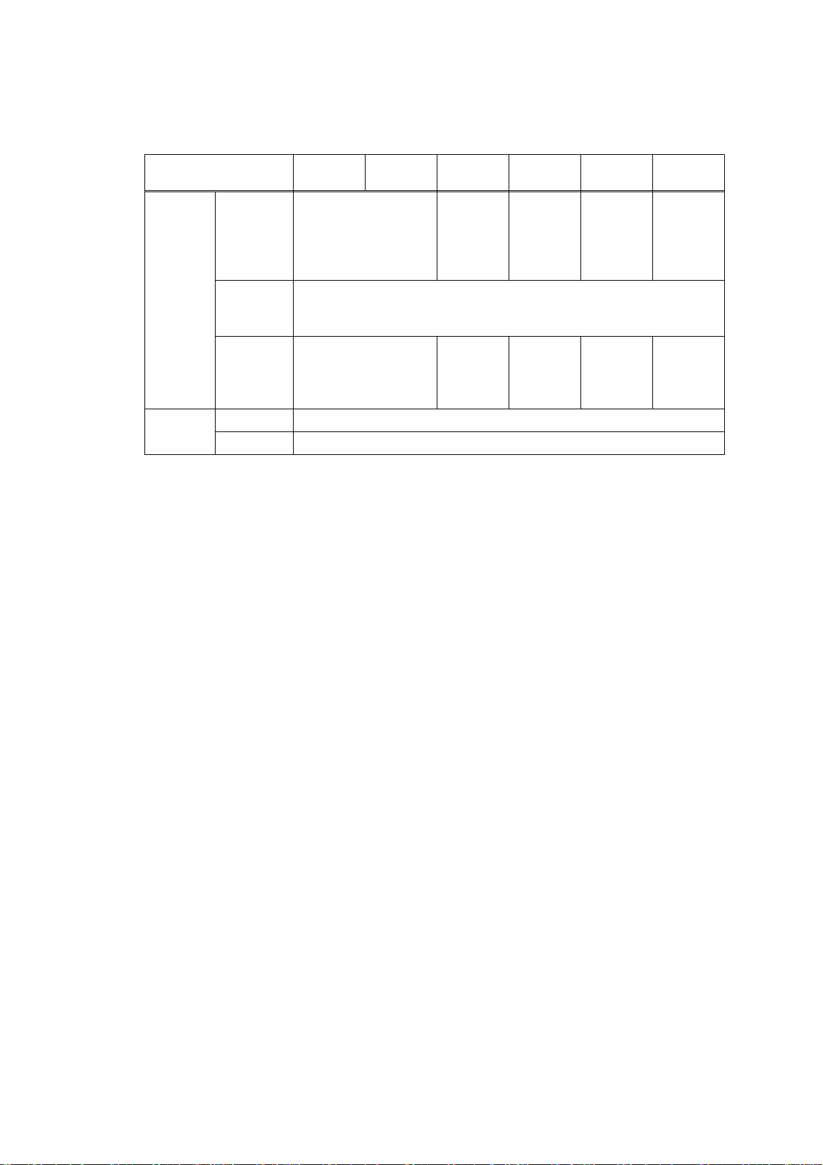
The function comparative table for models as describ ed in this Service Manual are shown blow.
Model
Panel display LED LED LED LED LED LCD
Network N/A Wired Wired
Lower Tray N/A N/A Yes N/A Yes N/A
Ethernet 10/100
BASE-TX
HL-
5340D
N/A Yes Yes Yes Yes Yes
HL-
5350DN
HL-
5350DNLT
HL-
5370DW
Wired/
Wireless
HL-
5370DWT
Wired/
Wireless
HL-
5380DN
Wired
Confidential
Page 3

PREFACE
This service manual contains basic information required for after-sales service of the laser
printer (hereinafter referred to as "this machine" or "the printer"). This information is vital to the
service technician to maintain the high printing quality and perfo rm a nc e of th e pr int er.
This service manual covers the HL-5340D/5350DN/5350DNLT/5370DW/5370DWT/5380DN
printers.
This manual consists of the following chapters:
CHAPTER 1: SPECIFICATIONS
Provides specifications of each model, which enables you to make a comparison of the
different models.
CHAPTER 2: THEORY OF OPERATION
Gives an overview of the printing mechanisms as well as the sensors, actuators, and co ntrol
electronics. It aids in understanding the basic principles of operations as well as locating
defects for troubleshooting.
CHAPTER 3: ERROR INDICATION AND TROUBLESHOOTING
Details of error messages and codes that the incorporated self-diagnostic function of the
machine will display if any error or malfunction occurs. If any error message appears, refer
to this chapter to find which parts should be checked or replaced.
The latter half of this chapter provides sample problems that could occur in the main sections
of the machine and related troubleshooting procedures.
CHAPTER 4: PERIODIC MAINTENANCE
Details of consumable parts and periodical maintenance parts. This chapter also covers
procedures for disassembling and assembling periodical maintenance parts.
CHAPTER 5: DISASSEMBLY/REASSEMBLY
Details of procedures for disassembling and assembling of the machine together with related
notes. The disassembly order flow provided enables you to see at a glance the quickest way
to get to parts involved.
At the start of a disassembly job, you can check the disassembly order flow that guides you
through a shortcut to get to the object parts.
This chapter also covers screw tightening torques and lubrication points to which the
specified lubrications should be applied during assembly jobs.
CHAPTER 6: ADJUSTMENTS AND UPDATING OF SETTINGS, REQUIRED
AFTER PARTS REPLACEMENT
Details of adjustments and updating of settings, which are required if the main PCB and
some other parts have been replaced. This chapter also cover s how to update the firmware.
CHAPTER 7: SERVICE MODE
Describes the maintenance mode which is exclusively designed for the purpose of checking
the settings and adjustments using the keys on the panel.
This chapter also covers hidden function menus, which activate settings and functions or
reset the parts life.
i
Confidential
Page 4

APPENDIX 1: FIRMWA RE SWITCHES (WSW)
APPENDIX 2: DELETION OF USER SETTING INFORMATION, etc.
Provides instructions on how to delete user setting information, etc recorded in the machine.
APPENDIX 3: SERIAL NUMBERING SYSTEM
APPENDIX 4: SCREW CATALOGUE
APPENDIX 5: REFERENCES
APPENDIX 6: GLOSSARY
Information in this manual is subject to change due to improvement or redesign of the product.
All relevant information in such cases will be supplied in service information bulletins (Technical
Information).
A thorough understanding of this printer, based on information in this service manual and
service information bulletins, is required for maintaining its print quality performance and for
improving the practical ability to find the cause of problems.
ii
Confidential
Page 5

REGULATION
For Europe and Other countries
■ Radio interference (220 to 240 volt model only)
This machine follows EN55022 (CISPR Publication 22)/Class B.
Before you use this product, make sure that you use one of the following interface cables.
(1) A shielded parallel interface cable with twisted-pair conductors and that it is marked
IEEE 1284 compliant.
(2) A USB cable.
The cable must not be more than 2 meters long.
■ IEC 60825-1 specification (220 to 240 volt model only)
This machine is a Class 1 laser product as defined in IEC 60825-1 specifications. The label
shown below is attached in countries where it is needed.
CLASS 1 LASER PRODUCT
APPAREIL À LASER DE CLASSE 1
LASER KLASSE 1 PRODUKT
This machine has a Class 3B laser diode which produ ces invisible l aser radiation in the laser
unit. You should not open the laser unit under any circumstances.
Caution
Use of controls or adjustments or performance of procedures other than those specified in
this User's Guide may result in hazardous radiation exposure.
For Finland and Sweden
LUOKAN 1 LASERLAITE
KLASS 1 LASER APPARAT
Varoitus!
Laitteen käyttäminen muulla kuin tässä käyttöohjeessa mainitulla tavalla saattaa altistaa
käyttäjän turvallisuusluokan 1 ylittävälle näkymättömälle lasersäteilylle.
Varning
Om apparaten används på annat sätt än i denna Bruksanvisning specificerats, kan
användaren utsättas för osynlig laserstrålning, som överskrider gränsen för laserklass 1.
iii
Confidential
Page 6

■ Internal laser radiation
Maximum radiation power: 5 mW
Wave length: 770 - 810 nm
Laser class: Class 3B
■ EU Directive 2002/96/EC and EN50419
(European Union only)
This equipment is marked with the above recycling symbol. It means that at the end of the
life of the equipment you must dispose of it separately at an appropriate collection point and
not place it in the normal domestic unsorted waste stream. This will benefit the environment
for all. (European Union only)
iv
Confidential
Page 7

For USA and Canada
■ Federal Communications Commission (FCC) Declaration of Conformity
(For USA)
Responsible Party: Brother International Corporation
100 Somerset Corporate Boulevard
P.O. Box 6911
Bridgewater, NJ 08807-0911
USA
Telephone: (908) 704-1700
declares, that the products
Product name: Laser Printer HL-5340D, HL-5350DN, HL-5350DNLT, HL-5370DW,
HL-5370DWT, HL-5380DN
Model number: HL-53
Product option: Lower Tray Unit LT-5300
complies with Part 15 of the FCC Rules. Operation is subject to the following two conditions:
(1) This device may not cause harmful interference, and (2) this device must accept any
interference received, including interference that may cause undesired operation.
This equipment has been tested and found to comply with the limits for a Class B digital
device, pursuant to Part 15 of the FCC Rules. These limits are desi gned to provide
reasonable protection against harmful interference in a residential installation. This
equipment generates, uses, and can radiate radio frequency energy and, if not installed and
used in accordance with the instructions, may cause harmful interference to radio
communications. However, there is no guarantee that interference will not occur in a
particular installation. If this equipment does cause harmful inter ference to radio or television
reception, which can be determined by turning the equipment off and on, the user is
encouraged to try to correct the interference by one or more of the following measures:
• Reorient or relocate the receiving antenna .
• Increase the separation between the equipment and receiver.
• Connect the equipment into an outlet on a circui t differen t from that to which the receiver is
connected.
• Consult the dealer or an experienced radio/TV technician for help.
Important
A shielded interface cable should be used to ensure compliance with the limits for a Class B
digital device. Changes or modifications not expressly approved by Brother Industries, Ltd.
could void the user's authority to operate the equipment.
v
Confidential
Page 8

■ Industry Canada Compliance Statement (For Canada)
This Class B digital apparatus complies with Canadian ICES-003.
Cet appareil numérique de la classe B est conforme à la norme NMB-003 du Canada .
■ Laser Safety (110 to 120 volt model only)
This machine is certified as a Class 1 laser product under the U.S. Depa rtment of Health and
Human Services (DHHS) Radiation Performance Standard according to the Radiation
Control for Health and Safety Act of 1968. This means that the machine does not produce
hazardous laser radiation.
Since radiation emitted inside the machine is completely confined within protective housings
and external covers, the laser beam cannot escape from the machine during any phase of
user operation.
■ FDA Regulations (110 to 120 volt model only)
The U.S. Food and Drug Administration (FDA) has implemented regulations for laser
products manufactured on and after August 2, 1976. Complianc e is ma nda tor y for pro d ucts
marketed in the United S tates. The following label on the back of the machine indicates
compliance with the FDA regulations and must be attached to laser products mar keted in the
United States.
MANUFACTURED:
Brother Technology (Shenzhen) Ltd.
NO6 Gold Garden Ind., Nanling Buji, Longgang, Shenzhen, China
This product complies with FDA performance standards for lase r products except for
deviations pursuant to Laser Notice No.50, dated July 26, 2001.
■ Internal laser radiation
Maximum radiation power: 5 mW
Wave length: 770 - 810 nm
Laser class: Class 3B
vi
Confidential
Page 9
SAFETY INFORMATION
■ Caution for Laser Product (WARNHINWEIS fur Laser drucker)
CAUTION: When the machine during servicing is operated with the cover open, the
regulations of VBG 93 and the performance instructions for VBG 93 are
valid.
CAUTION: In case of any trouble with the laser unit, replace the laser unit itself. To
prevent direct exposure to the laser beam, do not try to ope n the enclosure
of the laser unit.
ACHTUNG: Im Falle von Störungen der Lasereinheit muß diese ersetzt werden. Das
Gehäuse der Lasereinheit darf nicht geöffnet werden, da sonst
Laserstrahlen austreten können.
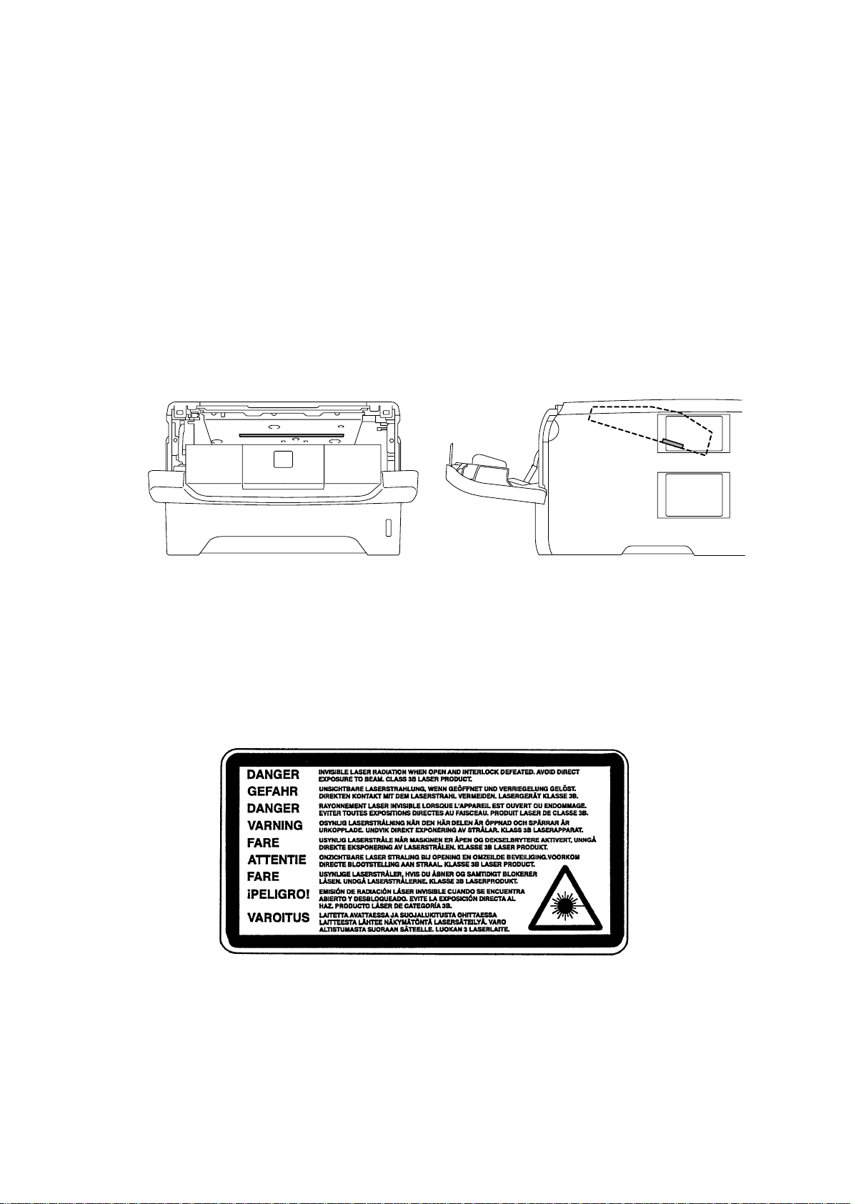
<Location of the laser beam window>
■ ADDITIONAL INFORMATION Additional Information
When servicing the optical system of the printer, be careful not to place a screwdriver or
other reflective object in the path of the laser beam. Be sure to take off any personal
accessories such as watches and rings before working on the printer. A reflected beam,
though invisible, can permanently damage the eyes.
Since the beam is invisible, the following caution label is attached on the laser unit.
vii
Confidential
Page 10
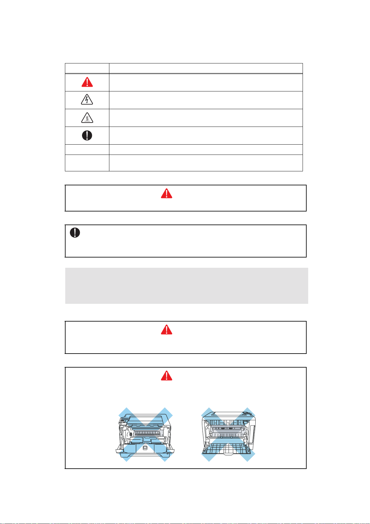
■ Definitions of Warnings, Cautions and Notes
The following conventions are used in this service manual:
Mark Contents
Warnings tell you what to do to prevent possible personal injury.
Electrical Hazard icons alert you to a possible electrical shock.
Hot Surface icons warn you not to touch machine parts that are hot.
Cautions specify procedures you must follow or avoid to prevent
possible damage to the machine or other objects.
Note Note Notes tell you useful tips when servicing the machine.
Memo
Memo Memo tells you bits of knowledge to help understand the
machine.
WARNING
Indicates warnings that must be observed to prevent possible personal injury.
CAUTION:
Indicates cautions that must be observed to service the printer properly or prevent
damage to the printer.
Note :
• Indicates notes and useful tips to remember when ser vic in g the prin te r.
**Listed below are the various kinds of "WARNING" messages included in this manual
.
WARNING
Always turn off the power switch and unplug the power cord from the power outlet
before accessing any parts inside the printer.
WARNING
Some parts inside the printer are extremely hot immediately after the printer is used.
When opening the front cover or back cover to access any parts inside the printer,
never touch the shaded parts shown in the following figures.
viii
Confidential
Page 11
WARNING
If you analyze malfunctions with the power plug inserted into the p ower outlet, special
caution should be exercised even if the power switch is OFF because it is a single
pole switch.
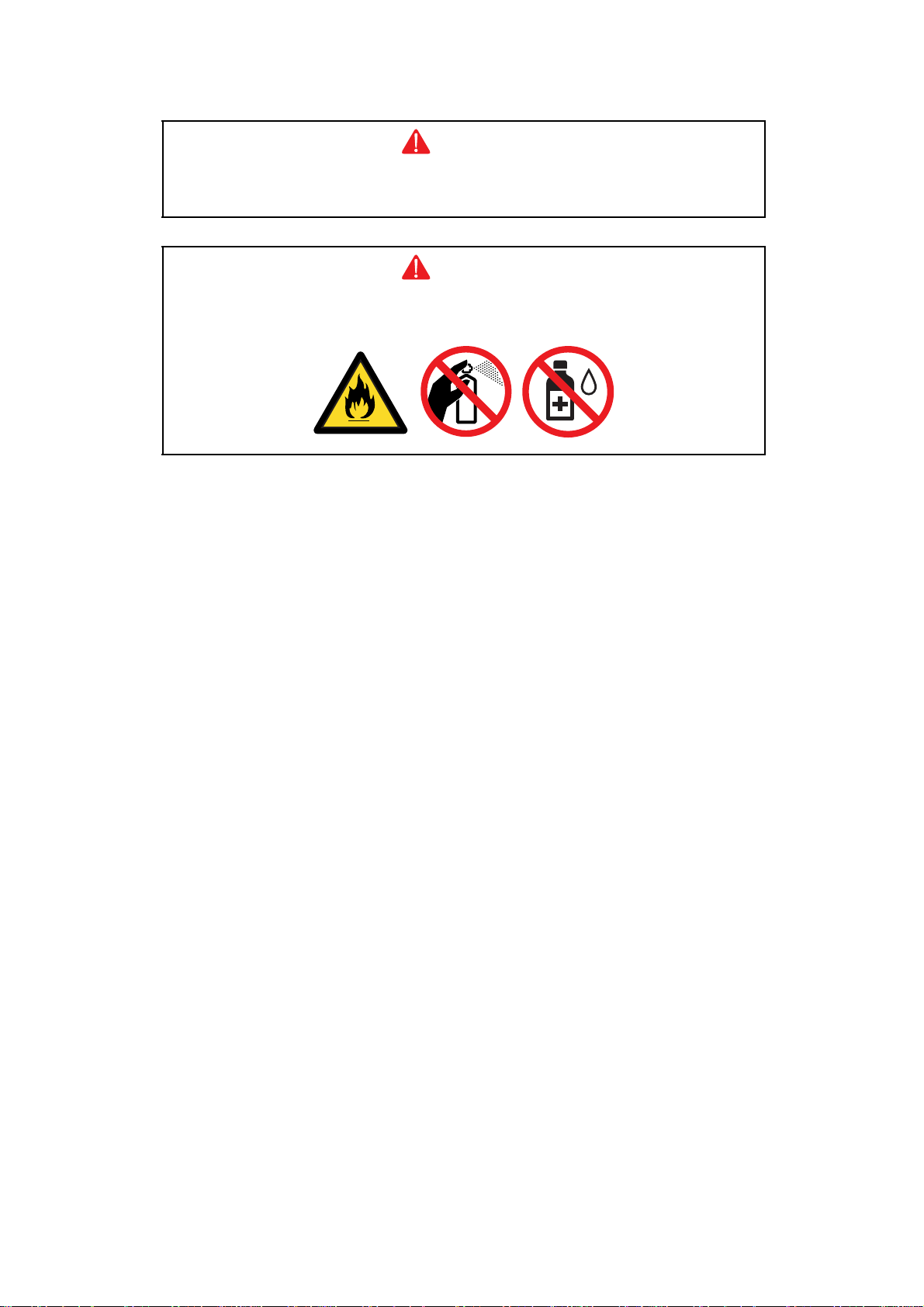
WARNING
DO NOT use flammable substances, any type of spray or any organic solvent/liquids
contains alcohol or ammonia to clean the inside or outside of the machine.
Doing this may cause a fire or electrical shock.
ix
Confidential
Page 12

CHAPTER 1
SPECIFICATIONS
Page 13

CHAPTER 1
SPECIFICATIONS
This chapter lists the specifications of each model, which enables yo u to make a comp arison
of different models.
CONTENTS
1. COMPONENTS.............................................................................................................1-1
2. SPECIFICATIONS LIST................................................................................................1-2
2.1 Printing ..................................................................................................................1-2
2.2 Functions...............................................................................................................1-3
2.3 Electronics and Mechanics....................................................................................1-5
2.4 Network Connectivity.............................................................................................1-6
2.5 Service Information................................................................................................1-8
2.6 Paper.....................................................................................................................1-9
2.6.1 Paper handling......................... .... ... ... ... .... ... ... ... .... ... ... ... ...........................1-9
2.6.2 Media specifications.................................................................................1-10
2.6.3 Type and size of paper.............................................................................1-10
2.7 Printable Area................................................................ .... ... ... ... ... .... ... ... ... .... ... ..1-12
2.8 Print Speeds with Various Settings......................................................................1-18
Confidential
Page 14
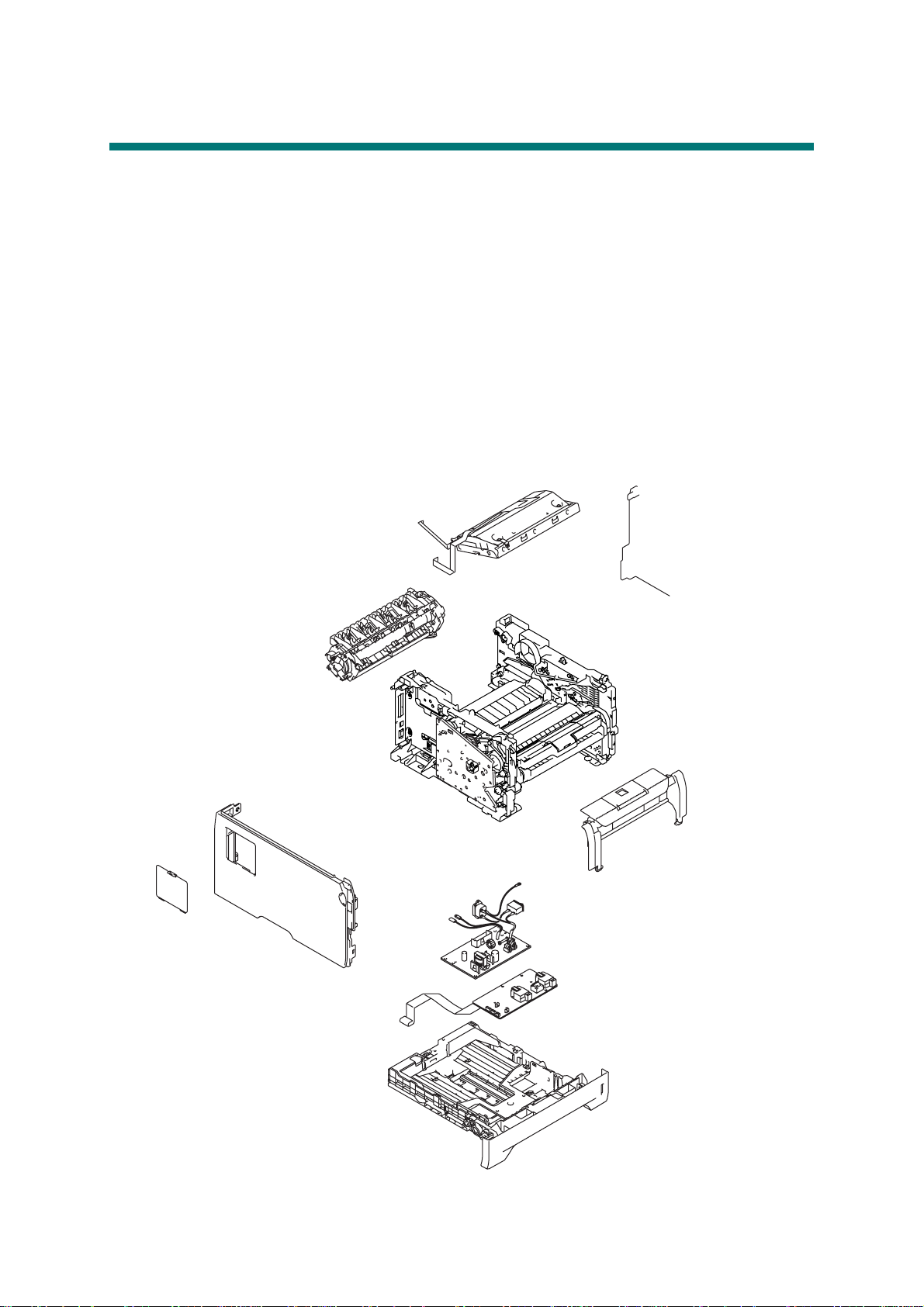
1. COMPONENTS
The equipment consists of the following major components:
Fig. 1-1
1-1
Confidential
Page 15
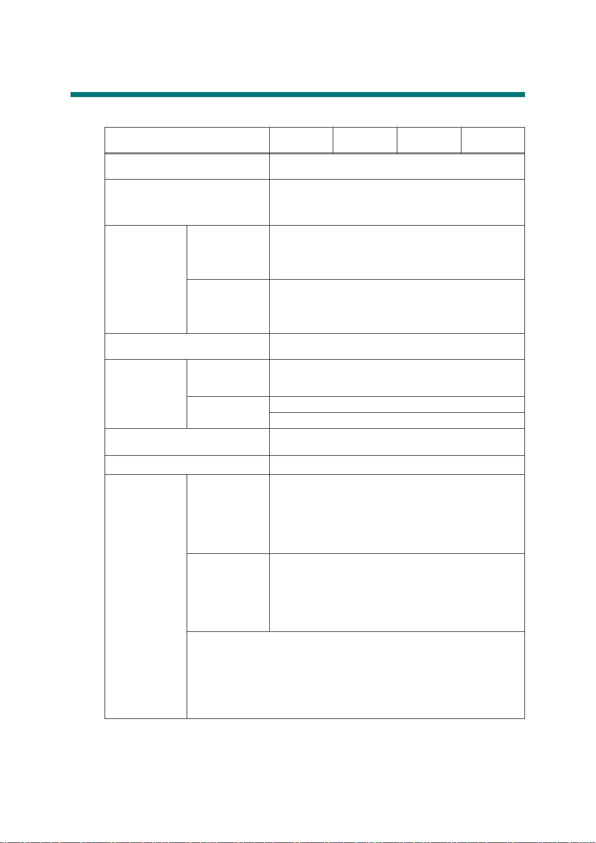
2. SPECIFICATIONS LIST
2.1 Printing
Model HL-5340D
HL-5350DN
HL-5350DNLT
HL-5370DW
HL-5370DWT
HL-5380DN
Print method Electrophotography by semiconductor laser beam
scanning
Laser Method: 1 polygon motor, 1 laser beam
Wavelength: 770 nm - 810 nm
Output: 5 mW (Max)
Laser class: Class3 B
Resolution
1200 dpi
HQ1200
(2400x600dpi)
*1
,
Windows® 2000/XP/ XP Professional x64 Edition, Windows
®
, Windows Server® 2003/ Windows Server® 2003 x
Vista
64 Edition, Windows Server
®
2008, Mac OS® X 10.3.9 or
greater, Linux
600 x 600 dpi
Windows® 2000/XP/ XP Professional x64 Edition, Windows
®
, Windows Server® 2003/ Windows Server® 2003 x
Vista
64 Edition/ Windows Server
®
2008, Mac OS® X 10.3.9 or
greater, DOS, Linux
Print mode Normal printing mode
Economy printing mode (Toner saving mode)
Print Speed
(A4/Letter)
Standard Up to 30/32 ppm
* When loading A4 or Letter-size paper from the
standard paper tray.
Duplex A4: Up to 13 sides per minute (6.5 sheets per minute)
Letter: Up to 14 sides per minute (7 sheets per minute)
Warm-up time
First print time
*2
*2
From sleep mode: less than 18 seconds
From power off
→ on: less than 28 seconds
Less than 8.5 seconds
Consumables Toner cartridge Life expectancy:
Standard: 3,000 pages/cartridge
High-capacity: 8,000 pages/cartridge
* When pr int i ng A4/Let te r- size paper in accordance with
ISO/IEC 19752.
Shelf life: 2 years without opening (6 months after
opening)
Drum unit Life expectancy: 25,000 pages/drum unit
Life expectancy will vary depending on number of
continuous printing pages. (Refer to CHAPTER 7 1.3
Service Mode "Printing for Maintenance".)
* When printing A4/Letter-size paper.
Shelf life: 2 years without opening (6 months after
opening)
The shelf life mentioned above is guaranteed under the normal condition as
below;
(Temperature) Normal condition: 0 to 40 °C
* Storage condition at the temperature of 40 to 50 °C: Up to 5 days
* Storage condition at the temperature of -20 to 0 °C: Up to 5 days
(Humidity) Normal condition: 35 to 85 %
* Storage condition at the humidity of 85 to 95 %: Up to 5 days
* Storage condition at the humidity of 10 to 35 %: Up to 5 days
*1
Using 1200 dpi setting (1200 x 1200 dpi) the print speed will be slower.
*2
The time may change if the machine is calibrating or registering itself.
Specifications are subject to change without notice.
1-2
Confidential
Page 16
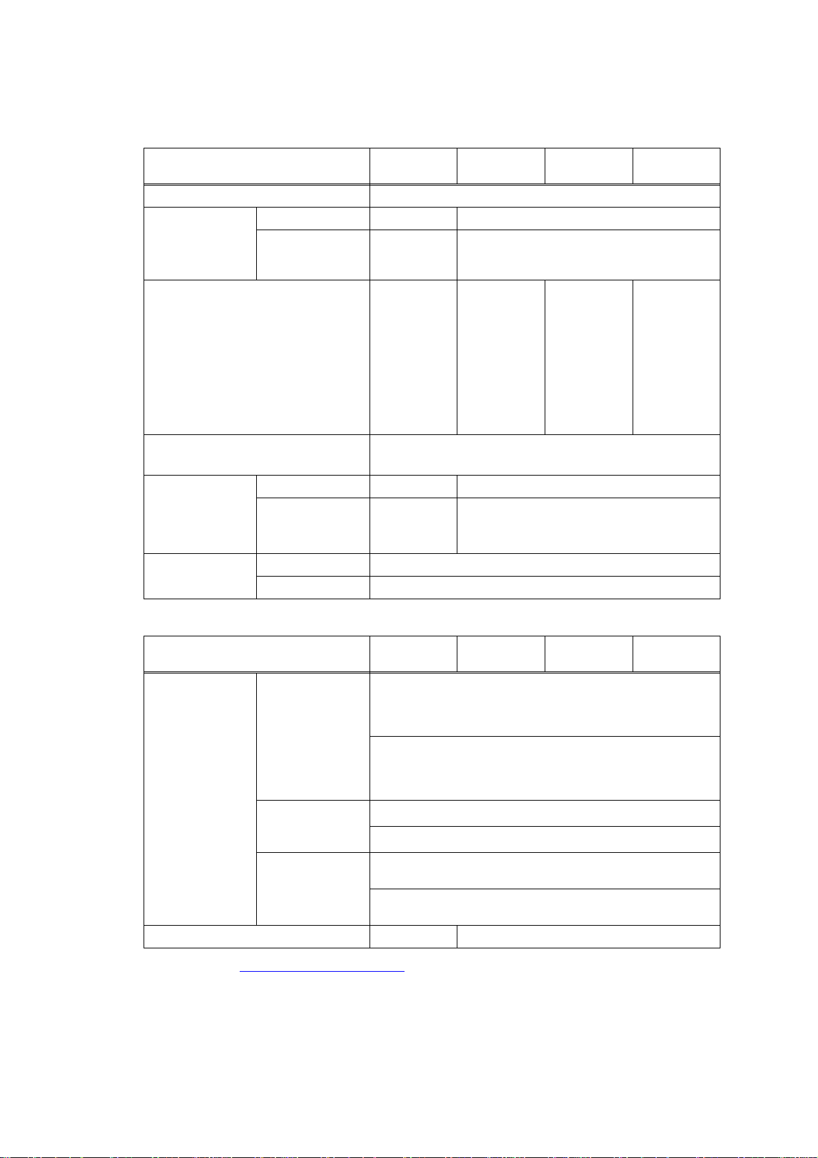
2.2 Functions
<Controller>
Model HL-5340D
HL-5350DN
HL-5350DNLT
HL-5370DW
HL-5370DWT
HL-5380DN
CPU 300 MHz
Memory Standard
Option
16 MB
1 DIMM slot;
32 MB
1 DIMM slot; expandable up to 544 MB
expandable
up to 528 MB
Interface IEEE 1284
Parallel, HiSpeed USB
2.0
IEEE 1284
Parallel, Hi-
Speed USB
2.0, Ethernet
10/100
BASE-TX
IEEE 1284
Parallel, HiSpeed USB
2.0, Ethernet
10/100
BASE-TX,
IEEE 1284
Parallel, HiSpeed USB
2.0, Ethernet
10/100
BASE-TX
Wireless
LAN IEEE
802.11b/g
Emulation
PCL6, BR-Script 3 (PostScript
®
3™), IBM Proprinter XL,
Epson FX-850
Network
Connectivity
Protocol N/A TCP/IP(10/100 BASE-TX Ethernet)
Management tool N/A BRAdmin Light, Web BRAdmin, Web
Based Management , BRAdmin
Professional 3
Resident fonts PCL 66 scalable fonts, 12 bitmap fonts, 13 bar codes
BR-Script 3 66 scalable fonts
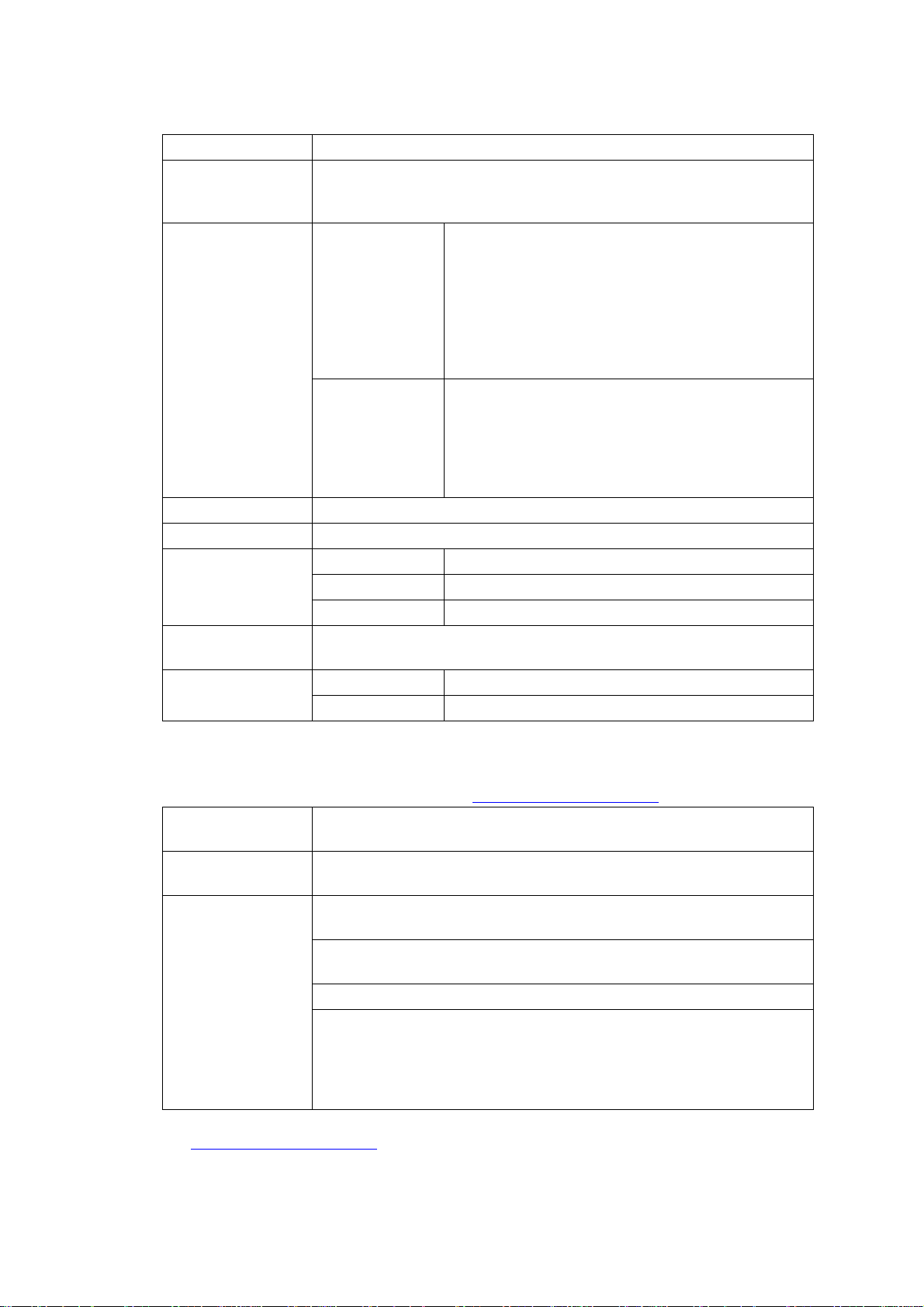
<Software>
Model HL-5340D
Printer driver Windows
®
PCL driver for Windows 2000 Professional, XP Home
HL-5350DN
HL-5350DNLT
Edition, XP Professional Edition, XP professional x64
Edition, Server 2003, Server 2003 x64 Edition, Vista,
Server 2008
BR-Script 3 (PPD file for Windows 2000 Professional, XP
Home Edition, XP Professional Edition, XP professional
x64 Edition, Server 2003, Server 2003 x64 Edition, Vista,
Server 2008)
Macintosh
®
Macintosh Printer Driver for Mac OS® X 10.3.9 or greater
BR-Script 3 (PPD file for Mac OS®
Linux * Linux printer driver for CUPS printing system (x86, x64
environment)
Linux printer driver for LPD/LPRng printing system (x86,
x64 environment)
Utility N/A Driver Deployment Wizard
Download from http://solutions.brother.com.
HL-5370DW
HL-5370DWT
X 10.3.9 or greater)
HL-5380DN
1-3
Confidential
Page 17

<System requirements>
Computer Platform &
Operating System Version
Windows
®
Windows
®
Vista
Windows
®
Server
x64 Edition
Windows
Professional
x64 Edition
Windows
®
Server
Windows
®
Server
Windows
Home Edition
Windows
Professional
Windows
2000
Professional
®
Apple
Macintosh
OS® X
®
10.3.9 - 10.4.3
OS
®
X
10.4.4 or
greater
2003
®
XP
2003
2008
®
XP
®
XP
®
Processor Speed
Intel® Pentium® 4 or
equivalent
64-bit supported CPU
AMD Opteron™
AMD Athlon™ 64
®
Intel
Xeon™ with Intel®
EM64T
®
Intel
Pentium® with
®
Intel
EM64T or
equivalent
AMDOpteron™
AMDAthlon™64
®
Intel
Xeon® with Intel®
EM64T
®
Intel
Pentium® 4 with
®
Intel
EM64T or
equivalent
®
Pentium® III or
Intel
equivalent
®
Pentium® 4 or
Intel
equivalent 64-bit
®
(Intel
64 or AMD 64)
supported CPU
Intel®Pentium® or
equivalent
Power PC G4/G5, Power
PC G3 350MHz
Power PC G4/G5, Intel®
Core™ Processor
Available
Hard
Disk
Space
Minimum
RAM
Recom-
mended
RAM
512MB 1GB 50MB
256MB 512MB 50MB
256MB 512MB 50MB
256MB 512MB 50MB
512MB 2GB 50MB
128MB 256MB 50MB
64MB 256MB 50MB
128MB 256MB 80MB
512MB 1GB 80MB
1-4
Confidential
Page 18

2.3 Electronics and Mechanics
Model
Power
consumption
Noise level Sound
Temperature Operating: 10 to 32.5°C (50 to 90.5 °F)
Humidity Operating: 20 to 80 % (non condensing)
Dimensions of the main
body (WxDxH)
Weight the main
Printing Average510 W at 25 °C (77 °F)
Standby Average 85 W at 25 °C (77 °F)
Sleep
Pressure
Sound
power
body with
Carton
the main
body
without
Carton
HL-
5340D
Average 8
W at 25 °C
(77 °F)
Printing: 54 dB (A)
Stan dby: 35 dB (A)
Printing: LWAd = 7.0 Bell (A)
Stan dby: LWAd = 4.6 Bell (A)
Non operating: 0 to 40°C (38 to 104 °F)
Storage: -20 to 40° C (-4 to 104 °F)
Storage: 10 to 85 % (non condensing)
371x384x246mm
(14.6x15.1x9.7in.)
11.7kg
(25.8lb)
9.5kg
(20.9lb)
HL-
5350DN
Average 9 W at 25 °C (77 °F)
HL-
5350DNLT
371x384x
347mm
(14.6x15.
1x13.7in.)
19.5kg
(42.9lb)
12.2kg
(26.9lb)
HL-
5370DW
371x384x
246mm
(14.6x15.
1x9.7in.)
11.7kg
(25.8lb)
9.5kg
(20.9lb)
HL-
5370DWT
371x384x
347mm
(14.6x15.
1x13.7in.)
19.5kg
(42.9lb)
12.2kg
(26.9lb)
HL-
5380DN
Average
12 W at 25
°C (77 °F)
393x384x
259mm
(15.5x15.
1x10.2in.)
11.9kg
(26.2lb)
9.5kg
(20.9lb)
1-5
Confidential
Page 19

2.4 Network Connectivity
<Ethernet wired network>
Network node type NC-6800h
Operating system
support
Protocol support TCP/IP: IPv4 ARP, RARP, BOOTP, DHCP, APIPA (Auto IP),
Network type 10/100 BASE-TX Ethernet network
Network printing Windows Vista
Windows Vista
Professional x64 Edition, Windows Server
Edition/Professional, Windows
or greater
TCP/IP: IPv6
2000 TCP/IP printing
Mac OS
®
, Windows Server® 2003 x64 Edition, Windows® XP
®
2000 Professional, Mac OS® X 10.3.9
WINS/NetBIOS name resolution, DNS Resolver,
mDNS, LLMNR responder, LPR/LPD, Custom Raw
Port/Port9100, IPP/IPPS, FTP Server, TELNET
Server, HTTP/HTTPS server, TFTP client and
server, SMTP Client, APOP, POP before SMTP,
SMTP-AUTH, SNMP v1/v2c/v3, ICMP, LLTD
responder, Web Services Print
*1
NDP, RA, DNS resolver, mDNS, LLMNR responder,
LPR/LPD, Custom Raw Port/Port9100, IPP/IPPS,
FTP Server, TELNET Server, HTTP/HTTPS server,
TFTP client and server, SMTP Client, APOP, POP
before SMTP, SMTP-AUTH, SNMPv1/v2c/v3,
ICMPv6, LLTD responder, Web Services Print
®
, Windows Server® 2003, Windows® XP and Windows®
®
X 10.3.9 or greater printing
®
2003, Windows® XP Home
*1
If you want to use the IPv6 protocol, visit http://solutions.brother.com for more information.
Management utility BRAdmin Professional 3
*2
for Windows
(Brother original Windows utility for printer and server management)
Web BRAdmin
*2
for Windows
(Server based management utility / Windows IIs (4.0/5.0) mode only)
Web Based Management
(Printer and print server management throuth web browser)
recommend Microsoft Internet Explorer 6.0 (or greater), Fire fox 1.0 (or
greater) for Windows
Safar: 1.2 (or greater) for Macintosh
BRAdmin Light for Windows and Macintosh
*2
BRAdmin Professional 3 and Web BRAdmin are available as a download from
http://solutions.brother.com
.
1-6
Confidential
Page 20
<Wireless network>
Network node type NC-7600w
Operating system
support
Windows Vista
Professional x64 Edition
2000, Mac OS
Protocol support TCP/IP: IPv4 ARP, RARP, BOOTP, DHCP, APIPA (Auto IP),
TCP/IP: IPv6
Network type IEEE 802.11b/g wireless
Frequency 2412 - 2472 MHz
RF channel US/Canada 1 - 11
Europe/Oceania 1 - 13
Japan 1 - 14
Communication
Infrastructure, Ad-hoc 802.11 b
mode
Data rate 802.11 b 11/5.5/2/1 Mbps
802.11 g 54/48/36/24/18/12/11/9/6 Mbps
*1
A wireless network connection is supported only between the Brother printer and an
access point for PC's running Windows Server
Professional x64 Edition.
*2
If you want to use the IPv6 protocol, visit http://solutions.brother.com for more information.
Link distance 70 m (233 ft.) at lowest data rate (The distance rate will vary upon
environment and other equipment location.)
Network security WEP 64/128, WPA-PSK (TKIP), WPA2-PSK (TKIP & AES), LEAP,
EAP-FAST
Management utility BRAdmin Professional 3
(Brother original Windows utility for printer and server management)
Web BRAdmin
(Server based management utility / Windows IIs (4.0/5.0) mode only)
Web Based Management
BRAdmin Light for Windows and Macintosh
(Printer and print server management throuth web browser)
recommend Microsoft Internet Explorer 6.0 (or greater), Fire fox 1.0 (or
greater) for Windows
Safar: 1.2 (or greater) for Macintosh
*3
BRAdmin Professional 3 and Web BRAdmin are available as a download from
http://solutions.brother.com
®
, Windows Server® 2003 x64 Edition*2, Windows® XP
®
X 10.3.9 or greater
*1
, Windows® 2003, Windows® XP, Windows®
WINS/ NetBIOS name resolution, DNS Resolver,
mDNS, LLMNR responder, LPR/LPD, Custom Raw
Port/Port9100, IPP/IPPS, FTP Server, TELNET
Server, HTTP/HTTPS server, TFTP client and
server, SMTP Client, APOP, POP before SMTP,
SMTP-AUTH, SNMP v1/v2c/v3, ICMP, LLTD
responder, Web Services Print
*2
NDP, RA, DNS resolver, mDNS, LLMNR responder,
LPR/LPD, Custom Raw Port/Port9100, IPP/IPPS,
FTP Server, TELNET Server, HTTP/HTTPS server,
TFTP client and server, SMTP Client, APOP, POP
before SMTP, SMTP-AUTH, SNMPv1/v2c/v3,
ICMPv6, LLTD responder, Web Services Print
®
2003 x64 Edition and Windows® XP
*2
for Windows
*2
for Windows
.
1-7
Confidential
Page 21

2.5 Service Information
These are key service information to maintain the product.
Machine life: 200,000 pages
MTBF (Meantime between failure): Up to 40 0 0 ho ur s
MTTR (Meantime to repair): Average 0.5 hours
Monthly volume: 30,000 pages
Periodical replacement parts:
Parts Approximate Life (pages)
Fuser unit 100,000
Laser unit 100,000
PF kit China MP: 25,000
India MP: 12,000
Others MP: 50,000
* As for periodical replacement parts, refer to CHAPTER 4 in the Service Manual.
Tray 1/2/3: 100,000
Tray 1/2/3: 80,000
Tray 1/2/3: 100,000
1-8
Confidential
Page 22
2.6 Paper
2.6.1 Paper handling
Paper
Input
*1
Model
Standard
tray
HL-
5340D
250 sheets 500
HL-
5350DN
HL-
5350DNLT
sheets
5370DW
250
sheets
(250
sheets x 2
trays)
Multi-
50 sheets
purpose
tray
Option 250 sheets x 2
(Max. 500 sheets)
250
sheets x 1
(Max. 250
sheets)
Paper
Output
*1
Calculated with 80 g/m2 (20 lb) paper.
*2
Not supported for Linux driver and PS driver (except Ma c PS driver ).
Face-down 150 sheets
*1
Face-up 1 sheet
250
sheets x 2
(Max. 500
sheets)
HL-
HL-
5370DWT
500
sheets
(250
sheets x 2
trays)
250
sheets x 1
(Max. 250
sheets)
HL-
5380DN
250
sheets
250
sheets x 2
(Max. 500
sheets)
1-9
Confidential
Page 23
2.6.2 Media specifications
Model HL-5340D
Media type Paper tray
(Standard)
Multi-purpose
tray
Plain paper, Bond paper, Recycled paper,
Transparencies
Plain paper, Thick paper, Bond paper, Recycled paper,
Envelope
HL-5350DN
HL-5350DNLT
*3
, Thin paper
*4
, Label, Transparencies *3, Thin paper
Optional tray Plain paper, Bond paper, Recycled paper, Thin paper
Media weight Paper tray
60 to 105 g/m
2
(16 to 28 lb)
(Standard/
Option)
2
Multi-purpose
60 to 163 g/m
(16 to 43 lb)
tray
Duplex 60 to 105 g/m
Media size Paper tray
(Standard/
Option)
U.S.A: A4, Letter, B5 (ISO), A5, A5 (Long Edge), B6
(ISO), Legal
Europe: A4, Letter , B5 (ISO), A5, A5 (Long Edge), B6
2
(16 to 28 lb)
*4
, Folio, A6, Exective
(ISO), A6, Executive
Multi-purpose
tray
Width: 69.8 to 216 mm (2.75 to 8.50 in.)
Length: 116 to 406.4 mm (4.57 to 16 in.)
Duplex U.S.A/Canada: Letter , Legal, Folio
Europe: A4
*3
Up to 10 sheets.
*4
Up to 3 sheets.
*5
Legal is not available in some regions outside the USA and Canada.
HL-5370DW
HL-5370DWT
HL-5380DN
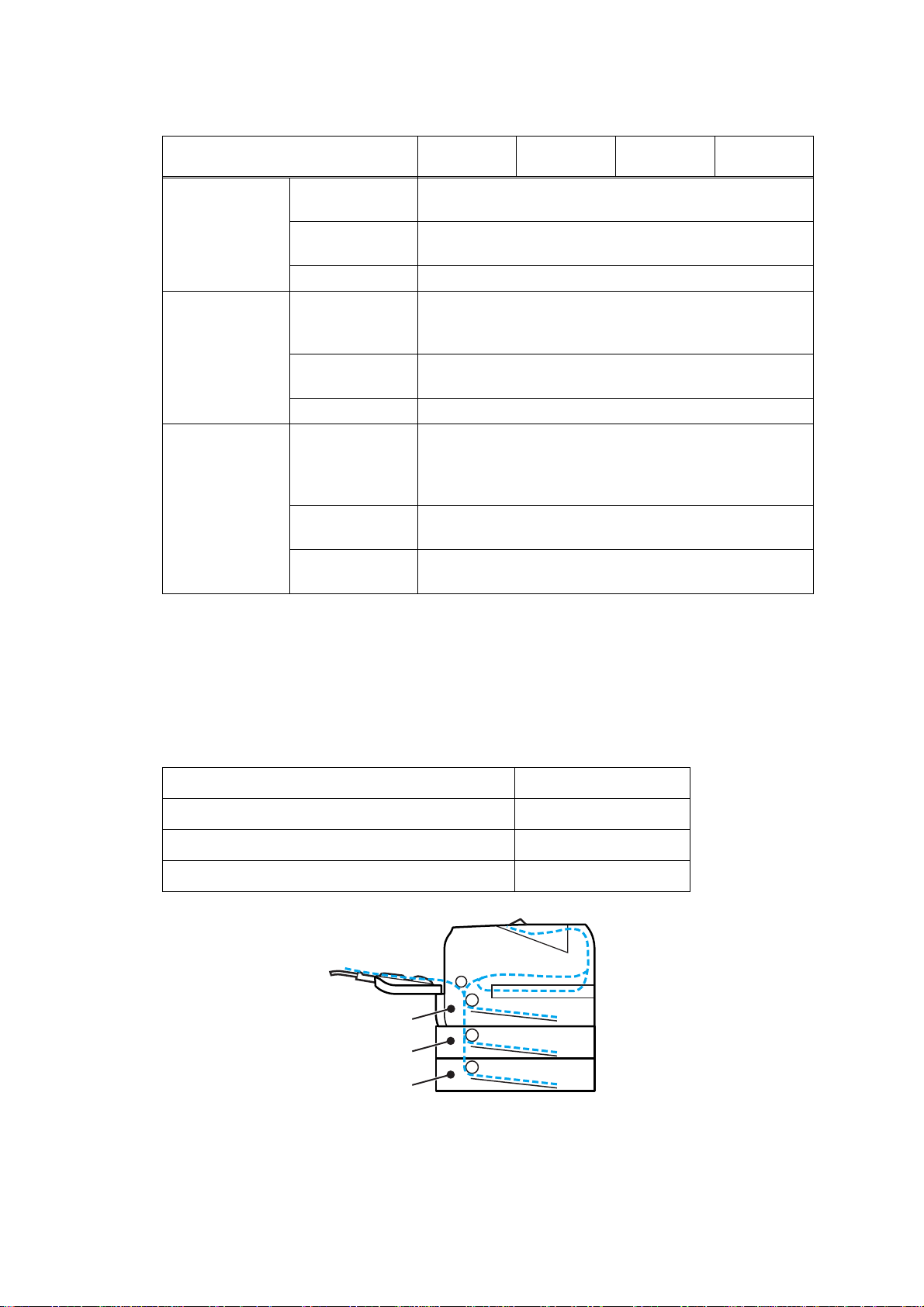
2.6.3 Type and size of paper
The printer loads paper from the installed paper tray or the multi-purpose tray. The name s
for the paper trays in the printer driver as follows;
Paper tray (T1) Tray 1
Multi-purpose tray MP tray
Optional lower tray unit Tray 2/Tray 3
Duplex unit for automatic duplex printing DX
Tray1
Tray2
Tray3
Fig. 1-2
1-10
Confidential
Page 24

<Media type>
Choose the
Tray 1/2/3 MP Tray DX
Plain paper
75 to 105 g/m
2
Yes Yes Yes
(20 to 28 lb)
Recycled paper Yes Yes Yes Recycled paper
Bond paper
Rough paper60 to 161 g/m
2
Yes
60 to105 g/m
(16 to 28 lb.)
2
Yes
60 to161 g/m
(16 to 43 lb.)
2
N/A
(16 to 43 lb)
Thin paper
60 to 75 g/m
2
Yes Yes Yes
(16 to 20 lb)
Thick paper
105 to 163 g/m
2
N/A Yes N/A
(28 to 43 lb)
Labels
N/A
Yes
A4 or Letter
N/A
Envelopes
N/A Yes N/A
media type from
the printer driver
Plain paper
Bond paper
Thin paper
Thick Paper or
Thicker Paper
Thicker Paper
Envelopes, Env.
Thin, Env.
Thick
Memo :
• Use paper that is made for plain-paper cop ying.
• Use papers that is 75 to 90 g/m2 (20 to 24 lb).
• Use neutral paper. Do not use acidic or alkaline paper.
• Use long-grain paper.
• This printer can use recycled paper that meets DIN 19309 specifications.
• DO NOT use ink jet paper because it may cause a p aper jam or damage your printer.
1-11
Confidential
Page 25
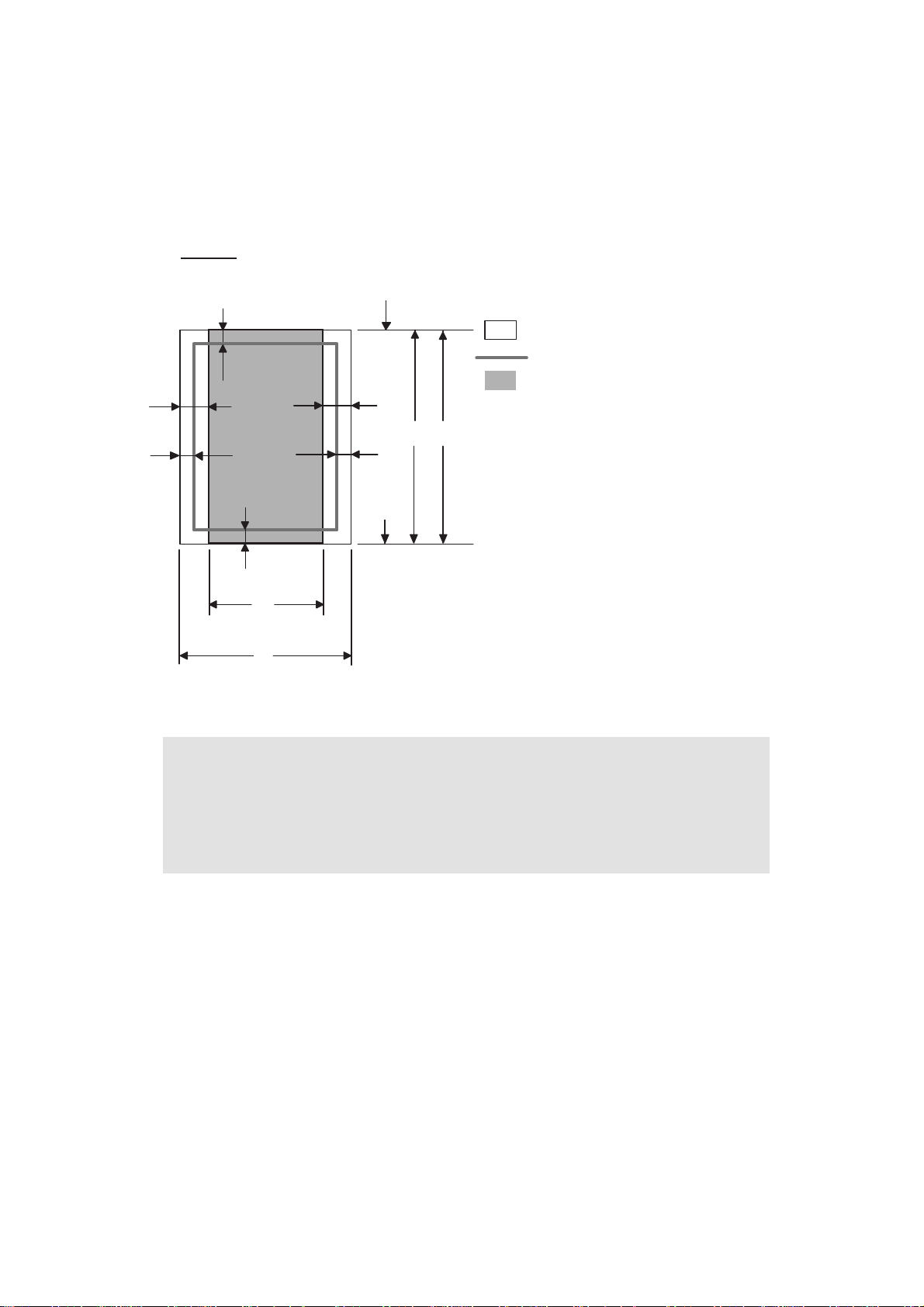
2.7 Printable Area
! PCL emulation
When using PCL emulation, the edges of the paper that cannot be printed on are shown
below.
Portrait
G
E
G
G
C
A
F
Physical page
Printable area
Logical page
E
B
D
G
F
B Physical page length
D
F
Maximum logical page length
Distance from edge of physical page to
edge of logical page
Note :
• "Logical page" shows the printable area for a PCL dr iver.
• "Printable area" shows mechanical printable area of the machine.
• Therefore, the machine can only print within the shaded area when you use a PCL
driver.
1-12
Confidential
Page 26

The table below shows the printable areas when printing on Portrait for each paper size.
SizeABCDEFG
Letter
Legal
Folio
Executive
A 4
A 5
A 6
B 5 (JIS)
B 5 (ISO)
B 6 (ISO)
Envelope
Monarch
Envelope
Com-10
Envelope DL
Envelope C5
HAGAKI
A4 Long
215.9mm
8.5"
(2,550dots)
215.9mm
8.5"
(2,550dots)
215.9mm
8.5"
(2,550dots)
184.15mm
7.25"
(2,175dots)
210.0mm
8.27"
(2,480dots)
148.5mm
5.85"
(1,754dots)
105.0mm
4.13"
(1,240dots)
182.0mm
7.1"
(2,130dots)
176.0mm
6.93"
(2,078dots)
125.0mm
4.92"
(1,476dots)
98.43mm
3.875"
(1,162dots)
104.7mm
4.125"
(1,237dots)
110.0mm
4.33"
(1,299dots)
162.0mm
6.38"
(1,913dots)
100.0mm
3.94"
(1,181dots)
210.0mm
8.27"
(2,480dots)
279.4mm
11.0"
(3,300dots)
355.6mm
14.0"
(4,200dots)
330.2mm
13.0"
(3,900dots)
266.7mm
10.5"
(3,150dots)
297.0mm
11.69"
(3,507dots)
210.0mm
8.27"
(2,480dots)
148.5mm
5.85"
(1,754dots)
257.0mm
10.11"
(3,033dots)
250.0mm
9.84"
(2,952dots)
176.0mm
6.93"
(2,078dots)
190.5mm
7.5"
(2,250dots)
241.3mm
9.5"
(2,850dots)
220.0mm
8.66"
(2,598dots)
229.0mm
9.01"
(2,704dots)
148.0mm
5.83"
(1,748dots)
405.0mm
15.94"
(4,783dots)
203.2mm
8.0"
(2,400dots)
203.2mm
8.0"
(2,400dots)
203.2mm
8.0"
(2,400dots)
175.7mm
6.92"
(2,025dots)
198.0mm
7.79"
(2,338dots)
136.5mm
5.37"
(1,612dots)
93.0mm
3.66"
(1,098dots)
170.0mm
6.69"
(2,007dots)
164.0mm
6.46"
(1,936dots)
164.0mm
4.44"
(1,334dots)
85.7mm
3.37"
(1,012dots)
92.0mm
3.62"
(1,087dots)
98.0mm
3.86"
(1,157dots)
150.0mm
5.9"
(1,771dots)
88.0mm
3.46"
(1,039dots)
198.0mm
7,79"
(2,338dots)
279.4mm
11.0"
(3,300dots)
355.6mm
14.0"
(4,200dots)
330.2mm
13.0"
(3,900dots)
266.7mm
10.5"
(3,150 dots)
297.0mm
11.69"
(3,507dots)
210.0mm
8.27"
(2,480dots)
148.5mm
5.85"
(1,754dots)
257.0mm
10.11"
(3,033dots)
250.0mm
9.84"
(2,952dots)
176.0mm
6.93"
(2.078dots)
190.5mm
7.5"
(2,250dots)
241.3mm
9.5"
(2,850dots)
220.0mm
8.66"
(2,598dots)
229.0mm
9.01"
(2,704dots)
148.0mm
5.83"
(1,748dots)
405.0mm
15.94"
(4,783dots)
6.3mm
0.2"
(75dots)
↑
↑
6.3mm
0.2"
(75dots)
6.0mm
0.2"
(71dots)
↑
↑
↑
↑
↑
6.3mm
0.2"
(75dots)
↑
6.0mm
0.24"
(71dots)
↑
6.0mm
0.24"
(71dots)
6.0mm
0.24"
(71dots)
0mm
0mm
0mm
0mm
0mm
0mm
0mm
0mm
0mm
0mm
0mm
0mm
0mm
0mm
0mm
0mm
4.2mm
0.16"
(50dots)
4.2mm
0.16"
(50dots)
4.2mm
0.16"
(50dots)
4.2mm
0.16"
(50dots)
4.2mm
0.16"
(50dots)
4.2mm
0.16"
(50dots)
4.2mm
0.16"
(50dots)
4.2mm
0.16"
(50dots)
4.2mm
0.16"
(50dots)
4.2mm
0.16"
(50dots)
4.2mm
0.16"
(50dots)
4.2mm
0.16"
(50dots)
4.2mm
0.16"
(50dots)
4.2mm
0.16"
(50dots)
4.2mm
0.16"
(50dots)
4.2mm
0.16"
(50dots)
1-13
Confidential
Page 27

SizeABCDEFG
DL Long
Edge
3X5
220.0mm
8.66"
(2,598dots)
76.2mm
3.00"
(900dots)
110.0mm
4.33"
(1,299dots)
127.0mm
5.00"
(1,500dots)
207.0mm
8.17"
(2,450dots)
63.5mm
2.50"
(750dots)
110.0mm
4.33"
(1,299dots)
127.0mm
5.00"
(1,500dots)
6.26mm
0.25"
(74dots)
6.35mm
0.25"
(75dots)
0mm
0mm
4.2mm
0.16"
(50dots)
4.2mm
0.16"
(50dots)
Note :
• The paper sizes indicated here should confirm to the nomina l dimensions specified
by JIS except B5 (ISO), B6 (ISO).
• The dot size is based on 300dpi resolutio n.
1-14
Confidential
Page 28
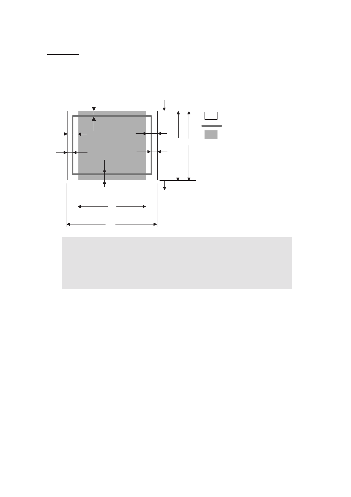
Landscape
G
E
G
G
F
E
D
B
G
B Physical page length
D Maximum logical page length
F Distance from edge of physical
page to edge of logical page
F
C
A
Note :
• "Logical page" shows the printable area for a PCL dr iver.
• "Printable area" shows mechanical printable area of the machine.
Physical page
Printable area
Logical page
• Therefore, the machine can only print within the shaded area when you use a PCL
driver.
1-15
Confidential
Page 29

The table below shows the printable areas when printing on Landscape for each paper size.
SizeABCDEFG
Letter
Legal
Folio
Executive
A 4
A 5
A 6
B 5 (JIS)
B 5 (ISO)
B 6 (ISO)
Envelope
Monarch
Envelope
Com-10
Envelope DL
Envelope C5
HAGAKI
A4 Long
279.4mm
11.0"
(3,300dots)
355.6mm
14.0"
(4,200dots)
330.2mm
13.0"
(3,900 dots)
266.7mm
10.5"
(3,150dots)
297.0mm
11.69"
(3,507dots)
210.0mm
8.27"
(2,480dots)
148.5mm
5.85"
(1,754dots)
257.0mm
10.11"
(3,033dots)
250.0mm
9.84"
(2,952dots)
176.0mm
6.93"
(2,078dots)
190.5mm
7.5"
(2,250dots)
241.3mm
9.50"
(2,850dots)
220mm
8.66"
(2,598dots)
229mm
9.01"
(2,704dots)
148mm
5.83"
(1,748dots)
405mm
15.94"
(4,783dots)
215.9mm
8.5"
(2,550dots)
215.9mm
8.5"
(2,550dots)
215.9mm
8.5"
(2,550dots)
184.15mm
7.25"
(2,175dots)
210.0mm
8.27"
(2,480dots)
148.5mm
5.85"
(1,754dots)
105.0mm
4.13"
(1,240dots)
182.0mm
7.1"
(2,130dots)
176.0mm
6.93"
(2,078dots)
125.0mm
4.92"
(1,476dots)
98.43mm
3.875"
(1,162dots)
104.7mm
4.125"
(1,237dots)
110mm
4.33"
(1,299dots)
162mm
6.38"
(1,913dots)
100mm
3.94"
(1,181dots)
210mm
8.27"
(2,480dots)
269.3mm
10.6"
(3,180dots)
345.5mm
13.6"
(4,080dots)
320.0mm
12.6"
(3,780dots)
256.6mm
10.1"
(3,030dots)
287.0mm
11.2"
(3,389dots)
200.0mm
7.87"
(2,362dots)
138.5mm
5.45"
(1,636dots)
247.0mm
9.72"
(2,916dots)
240.0mm
9.44"
(2,834dots)
166.4mm
6.55"
(1,960dots)
180.4mm
7.1"
(2,130dots)
231.1mm
9.10"
(2,730dots)
210.0mm
8.26"
(2,480dots)
219.0mm
8.62"
(2,586dots)
138mm
5.43"
(1,630dots)
395mm
15.55"
(4,665dots)
215.9mm
8.5"
(2,550dots)
215.9mm
8.5"
(2,550dots)
215.9mm
8.5"
(2,550dots)
184.15mm
7.25"
(2,175dots)
210.0mm
8.27"
(2,480dots)
148.5mm
5.85"
(1,754dots)
105.0mm
4.13"
(1,240dots)
182.0mm
7.1"
(2,130dots)
176.0mm
6.93"
(2,078dots)
125.0mm
4.92"
(1,476dots)
98.43mm
3.875"
(1,162dots)
104.7mm
4.12"
(1,237dots)
110mm
4.33"
(1,299dots)
162mm
6.38"
(1,913dots)
100mm
3.94"
(1,181dots)
210mm
8.27"
(2,480dots)
5.0mm
0.2"
(60dots)
↑
↑
5.0mm
0.2"
(60dots)
4.8mm
0.19"
(59dots)
↑
↑
↑
↑
↑
5.0mm
0.20"
(60dots)
↑
4.8mm
0.19"
(59dots)
↑
4.8mm
0.19"
(59dots)
4.8mm
0.19"
(59dots)
0mm
0mm
0mm
0mm
0mm
0mm
0mm
0mm
0mm
0mm
0mm
0mm
0mm
0mm
0mm
0mm
4.2mm
0.16"
(50dots)
4.2mm
0.16"
(50dots)
4.2mm
0.16"
(50dots)
4.2mm
0.16"
(50dots)
4.2mm
0.16"
(50dots)
4.2mm
0.16"
(50dots)
4.2mm
0.16"
(50dots)
4.2mm
0.16"
(50dots)
4.2mm
0.16"
(50dots)
4.2mm
0.16"
(50dots)
4.2mm
0.16"
(50dots)
4.2mm
0.16"
(50dots)
4.2mm
0.16"
(50dots)
4.2mm
0.16"
(50dots)
4.2mm
0.16"
(50dots)
4.2mm
0.16"
(50dots)
1-16
Confidential
Page 30

SizeABCDEFG
DL Long
Edge
3X5
110mm
4.33"
(1,299dots)
127mm
5.00"
(1,500dots)
220mm
8.66"
(2,598dots)
76.2mm
3.00"
(900dots)
102mm
4.00"
(1,199dots)
116.8mm
4.60"
(1,380dots)
220mm
8.66"
(2,598dots)
76.2mm
3.00"
(900dots)
4.0mm
0.16"
(50dots)
5.0mm
0.20"
(60dots)
0mm
0mm
4.2mm
0.16"
(50dots)
4.2mm
0.16"
(50dots)
Note :
• The paper sizes indicated here should confirm to the nomina l dimensions specified
by JIS except B5 (ISO), B6 (ISO).
• The dot size is based on 300 dpi resolution.
1-17
Confidential
Page 31

2.8 Print Speeds with Various Settings
Print speed is up to 30 ppm for A4 size and 32ppm for Letter size when loading A4 or Letter
size paper from the paper tray in the plain paper mode.
Actual print speed varies depending on the media type or paper size as shown in the tables
below;
<A4/Letter size>
Media type setting
Plain paper, Recycled paper 30/32 ppm
Plain paper thin 30/32 ppm
Thick paper, Envelope, Envelope thin, Label 15/16 ppm
Thicker paper, Bond paper, Envelope thick 3 ppm
Print speed
(for all models)
<Smaller size than A4 or Letter>
Media type setting
Plain paper, Recycled paper 0 to 90 second 32 ppm,
90 second or later 15 ppm
Plain paper thin 30/32 ppm
Thick paper, Envelopes, Envelopes thick,
Label, HAGAKI
Thicker paper, Bond paper, Envelopes thick 3 ppm
0 to 9 second 16 ppm,
9 second or later 15 ppm
Print speed
(for all models)
Note :
• The print speed may vary according to conditions, such as paper size and paper
tray.
• When a smaller size paper than A4 or Letter is printed, the temperature on both
edges of the fuser unit is much higher than the temperature on the center of the unit
where the paper is fed depending on the setting or model. Therefore, the print
speed is slowed in order to decrease the temperature on the edges after the
specified time, it is maximum print speed when you first start printing.
• The actual print speed varies depending on the paper size.
1-18
Confidential
Page 32

CHAPTER 2
THEORY OF OPERATION
Confidential
Page 33

CHAPTER 2 THEORY OF OPERATION
This chapter gives an overview of the scanning and printing mechanisms as well as the
sensors, actuators, and control electronic s. It aids in understanding the basic principles of
operation as well as locating defects for troubleshooting
CONTENTS
1. OVERALL......................................................................................................................2-1
1.1 General Block Diagram .........................................................................................2-1
2. ELECTRONICS.............................................................................................................2-2
2.1 General Block Diagram .........................................................................................2-2
3. MECHANICS.................................................................................................................2-3
3.1 Cross-section Drawing ..........................................................................................2-3
3.2 Cross-section Drawing ..........................................................................................2-4
3.2.1 Plate-up Function of the Paper Tray ..........................................................2-5
3.2.2 Paper supply ...................................... ... .... ... ... ... .... ... ... ... ... .... ... ... ..............2-6
3.2.3 Paper registration...................................................... ... ... ... .... ... .................2-7
3.2.4 Paper eject......................... ... ... .... ... ... ... ....................................... ... .... ... ... .2-8
3.2.5 Duplex printing ................................ ... ... .... ... ... ... .... ... ... ... ... .... ... .................2-9
3.2.6 Paper feeding from the MP tray ................................ ...............................2-10
3.2.7 Paper feeding from the LT tray (Tray 2 / Tray 3)......................................2-10
3.3 Toner Cartridge....................................................................................................2-11
3.3.1 Methods for Detecting and Counting Toner Life....................................... 2-11
3.3.2 Cartridge life.............................................................................................2-12
3.3.3 New toner detection .................................................................................2-13
3.4 Print.....................................................................................................................2-16
3.4.1 Basic Principle....................... .......................................... ... .... ..................2-16
3.4.2 Print Process............................................................................................2-17
3.5 Sensors position................................................................ ... ... ... ... .... ... ... ... .... .....2-22
Confidential
Page 34

1. OVERALL
1.1 General Block Diagram
Fig. 2-1 shows a general block diagram.
Control system
Extended RAM
SODIMM 144pin
RAM
16MB:
Netwark model
32MB:
No Netwark model
Video control block
supply block
Low-voltage power
Ethernet
10/100 Base TX
(Ethernet model)
Interface block
USB
Parallel
Wireless LAN
(Wireless LAN
model)
External device
supply block
High-voltage power
Image generation system
Laser unit
Drum unit
Charging
block
Engine control block
Transfer block
Exposure
drum
Developer unit
Developing block
Toner cartridge
Fig. 2-1
Drive block
(DC motor)
Paper dust
cleaner block
Operation block
(Control panel)
Paper tray
Fuser unit
Paper eject tray
Paper feed system
2-1
Confidential
Page 35

2. ELECTRONICS
2.1 General Block Diagram
(Main fan)
Main fan
Power supply fan
Sensor PCB
(PE+PEDGE)
MP sensor PCB
Tray1 solenoid
Regist solenoid
MP solenoid
Interlock switch
(Cover sensor)
Toner LED PCB
(Light emission)
Toner
sensor PCB
(Light
reception)
High-voltage
power supply
Regist front
sensor
Regist rear
sensor
Front relay
PCB
New toner
sensor
Wireless LAN
(Wireless LAN model)
Polygon motor
Laser diode PCB
Fig. 2-2
Main PCB
Low-voltage power supply
Rear relay
PCB
Paper eject
sensor
DX solenoid
LT PCB
LT PCB
Main motor
Panel PCB
DX unit sensor PCB
LT1
LT2
Fuser thermistor
LT Sensor PCB
(PE+PEDGE)
LT solenoid
LT Sensor PCB
(PE+PEDGE)
LT solenoid
2-2
Confidential
Page 36

3. MECHANICS
MP
3.1 Cross-section Drawing
Eject roller ASSY 2
Back cover
Heat roller
Eject roller ASSY 1
Paper eject actuator
Pressure roller
Duplex unit
Paper tray
Paper tray (LT unit)
Transfer rollerPaper stack lever
Exposure drumCorona wireLaser unit
Develop roller
MP tray
Regist roller
Separation roller MP
Separation pad MP
Paper feed roller MP
Regist actuator rear
Regist actuator front
Feed roller TR
Edge actuator
Separation roller
Separation pad
Paper feed roller
PE actuator
Plate
Feed roller LT
Edge actuator LT
Separation roller LT
Separation pad LT
Paper feed roller LT
PE actuator LT
Plate LT
Fig. 2-3
2-3
Confidential
Page 37

3.2 Cross-section Drawing
The following figure shows the paper feeding paths.
DX path
Paper tray path
MP path
LT path
Fig. 2-4
2-4
Confidential
Page 38

3.2.1 Plate-up Function of the Paper Tray
The plate ASSY in the paper tray is pushed up with the motor dr ive and not with th e spring in
order to maintain the constant pressure to the feed roller and to give the paper feeding
performance.
When the paper tray (Tray1 cassette) is installed into the printer, the lift gear 46 is rotated,
and the motor drive is transmitted to the plate ASSY so that it is pushed up.
P/P clutch hook A2
P/P clutch hook A1
Plate ASSY
Plate up plate
P/P gear 29 clutch cam
Lift gear 46
P/P clutch hook B
P/P differential
P/P gear 22/B23
tray drive
Gear 15
Gear 21-16
Fig. 2-5
When the feed roller is pushed up, the hook is released by the lift arm, and the rotation of the
clutch gear is stopped. Then, the pressure plate is stopped to push up.
Stop
Fig. 2-6
When the tray is pulled out from the printer , the pr essure plate is returned to the original position.
When the tray is put into the printer, the above operatio n is performe d from the start again.
2-5
Confidential
Page 39

3.2.2 Paper supply
The feed roller picks up a few sheets or one sheet of paper from the paper tray every time it
is rotated and feeds it to the separation roller.
Pinch roller
Regist roller
Regist actuator rear
Regist actuator front
PE actuator
PlatePaper
Feed roller
Pressure roller
Edge actuator
Separation roller
Feed roller
Fig. 2-7
The main motor drive power is transmitted to the gears, and the feed roller and separation
roller are rotated. Then, the paper is gripped between the separation roller and separation
pad and separated into individual sheets.
The paper drawn out of the paper tray pushes against the regist front actuator, and the
absence of paper is detected by the actuator movement. The tail edge actuator detects the
end of the paper fed.
2-6
Confidential
Page 40

3.2.3 Paper registration
After the paper top position is detected by the regist actuator front, the paper, separated into
individual sheets by the separation roller, is fed further for a specified time, and the paper top
position reaches the regist roller so that the paper skew is adjusted. Then, the regist
solenoid is turned on, the regist roller starts turning, and the paper is fed to the transfer roller
in the drum/toner ASSY.
Exposure drum
Transfer roller
Drum/toner ASSY
Regist actuator rear Regist roller
Fig. 2-8
Regist actuator front
Separation roller
The regist actuator rear in the path from the regi st roller to the transfer roller controls the first
print position on the paper. The printer starts transferring an image when a definite time
passes after the paper is passed through the regist actuator rear.
2-7
Confidential
Page 41

3.2.4 Paper eject
After the printing image on the exposure drum is transferred onto the paper, the paper is fed
to the fuser unit to fix unfixed toner onto the paper by the heat roller and the pressu re roller in
the fuser unit.
Afterwards, the paper is ejected from the fuser unit. The paper eject actuator detects
whether the paper is ejected correctly or not.
After the paper exits from the heat roller, the paper is turned by the back cover and ejected
face down into the top output tray through the eject roller 2.
Outer chute
Eject roller ASSY 2
Eject roller ASSY 1
Heat roller
Paper eject actuator
Pressure roller
Fig. 2-9
When a paper jam occurs, the main moto r rotates conve rsely to throw out the en gagement of
the gear. Consequently, the eject roller ASSY 2 is released so that the jammed recording
paper is removed easily.
2-8
Confidential
Page 42

3.2.5 Duplex printing
After the paper exits from the eject roller ASSY 2 with the front of sheet printed, the eject
roller ASSY 2 rotates conversely and feeds the paper to the DX unit, where the paper skew is
adjusted.
Afterwards, the paper is ejected from the DX unit to the path through the regist roller and the
transfer roller to the transfer block in the drum un it again for process of printing on th e back of
sheet.
Eject roller ASSY 2
Back cover
Heat roller
Exposure drum
Rear chute
ASSY
Eject roller
ASSY 1
Pressure
roller
Duplex unit
Transfer roller
Regist actuator rear
Fig. 2-10
Note :
• The duplex printing prints the 1st page after printing the 2nd page first.
For example, when prints the four pages, prints in order to 2nd page to 1st page to
4th page to 3rd page.
Pinch roller
Regist actuator
front
Regist roller
2-9
Confidential
Page 43

3.2.6 Paper feeding from the MP tray
The separation roller MP is connected with the feed roller through the gear in the MP roller
holder ASSY. When the separation roller is driven, therefore, the feed roller is also driven. At
this time, the recording paper is drawn out of the MP tray by rotation of the paper feed roller
MP contacted with the recording paper. The drawn recording paper is separated into
individual sheets by the separation roller MP.
Separation roller MP
MP roller holder ASSY
Paper feed roller MP
Separation pad ASSY MP
Fig. 2-11
3.2.7 Paper feeding from the LT tray (Tray 2 / Tray 3)
The motor drive is transmitted to the some gears to rotate the feed roller, then the recording
paper is drawn out of the LT tray. The drawn recording paper is separa ted into individual sheet
by the separation roller and the separation pad, and fed to the printer by the feed roller TR.
MP tray cover ASSY
Feed roller TR
Separation roller
Separation pad
Paper
Plate
Fig. 2-12
2-10
Paper feed roller
Confidential
Page 44

3.3 Toner Cartridge
3.3.1 Methods for Detecting and Counting Toner Life
When the machine detects the toner life end, "Replace Toner" is displayed in the state of
LCD model and the red Status LED lights on, and the Toner LED lights on at the same time.
in the state of LED model. The toner life is displayed through the follo win g two way s. Fir s t,
such indication is displayed when detection is performed by the toner sensor; second, it is
displayed at the time when a rotation rate of the develop roller reaches its upper limit.
(1) Detection by the toner senso r
The low amount of toner remaining can be detected by checking the imperviousness to
light of the toner in the cartridge by means of the transmissive photosenso r.
(2) Detection by means of rotation rates of the develop roller reached its upper limit
The machine counts the accumulated number of the develop roller.
2-11
Confidential
Page 45

3.3.2 Cartridge life
A new toner cartridge can print approximately 3,000 (st anda rd toner) or approx imately 8,000
(high yield toner) A4 or Letter size single-sided pag es at normal duty (ISO/IEC19752) . In the
case of low-duty printing, if the number of printed pages are reached the cartridge life,
"Replace Toner" is indicated by lighting Toner LED (HL-5340D/5350DN/5350DNLT/
5370DW/5370DWT) or "Replace Toner" message appears on the LCD panel (HL-5380DN)
before the toner runs out because the developer roller surface or other toner sealing is worn
out due to a rotation of the rollers.
Toner life
Full
Normal-duty
(ISO/IEC19752)
Low-duty
High-duty
Low
Cartridge Life End
Empty
pages
Toner EmptyToner Empty
Memo :
• If reached the cartridge life end, "Replace Toner" message appears even if the
toner is contained.
<Cartridge Life>
As the deterioration of toner will be less in case of printing more pages continually once time
than usual, the more printing pages per job, the more prin table pages of toner cartridge.
Table: The relationship between the average printing pages per job and the toner cartridge life
Average printed pages
(page/job)
Cartridge Life (Standard) 3,500 5,274 6,346 7,064 7,579 7,966 8,267 8,508
Cartridge Life (High Yield) 9,500
Increasing the number of times of power switch ON and warming operation in company with
opening or closing cover will also cause the deterioration of toner, so the more frequency
those operations be taken, the less pages the toner cartridge can print.
Table: The toner cartridge lives in case of pressing power switch Off/ON before printing.
Average printed pages
(page/job)
Cartridge Life (Standard) 1,925 3,263 4,246 5,000 5,596 6,079 6,478 6,814
Cartridge Life (High Yield) 5,225 8,856
12345678
14,315 17,225 19,174 20,571 21,621 22,439 23,094
12345678
11,526 13,571 15,189 16,500 17,584 18,496
2-12
Confidential
Page 46

3.3.3 New toner detection
(1) The main motor will drive gear (4) through the interconnection of other gears.
(2) When gear (4) is rotated, rib A on that gear will push against the new toner actuator; the
new toner sensor will detect the actuator motion, and the machine detects that a new
toner cartridge has been installed.
(3) The standard toner cartridge has Rib A and Rib B on gear (4).
When the toner actuator is pushed twice, the two signals that are generated by the new
toner sensor, tell the machine that a standard toner cartridge has been inst alled.
(4) The high yield toner cartridge only has Rib A on gear (4).
When the toner actuator is pushed once, the signal that is generated by the new toner
sensor, tell the machine that a high yield toner cartridge has been installed.
<Printer side view when a new toner cartridge is installed>
Toner cartridge
New toner sensor
Relay front PCB ASSY
Gear (1)
Fig. 2-13
Gear (2)
New toner actuator
Gear (4)
Rib B
Rib A
Gear (3)
2-13
Confidential
Page 47

When the new toner detection switch detects that the toner cartridge is replaced with a new
one, the developing bias voltage is initialized at the same time.
The toner used for the printer has a property that print density is light first and gradually
darker in the course of usage. The developing bias controls the toner property so that the
print density is constant from first to last.
Toner property Actual control
[Density]
[Voltage]
Print density
Bias voltage
[Used toner amount]
[Density]
[Voltage]
Print density
Bias voltage
[Used toner amount]
To obtain a print result of a constant density all the time, the printer count s the number of print
pages immediately after the toner cartridge is replaced and changes the bias voltage
according to the accumulated number of prints with the toner cartridge.
The bias voltage is changed with the steps described below:
(1) When the new toner sensor detects that the toner cartridge is replaced with a new (full)
one, the developing bias is set to 400V (initialized).
(2) After that, the bias voltage is stepped down according to the number of pri nts. Ultimately,
the bias voltage is 275V.
<When a new toner cartridge is inserted after "Replace Toner" is displayed>
Corresponding counter, Setting value Operation
Counter of toner cartridge changes +1
Page counter for each toner cartridge Reset (0)
Coverage for each toner cartridge Reset (0)
Developing bias voltage Reset (Initial setting)
2-14
Confidential
Page 48

<When a toner cartridge in use is inserted after "Replace Toner" is displayed
by toner sensor detection
A count value before changes is continuously indicated as a rotation rate of the develop
roller. Irrespective of the amount of toner, printing becomes disabled when the rotation rate
reaches the upper limit.
Corresponding counter, Setting value Operation
Counter of toner cartridge changes No count up
Page counter for each toner cartridge Continued
Coverage for each toner cartridge Continued
Developing bias voltage Reset (Initial setting)
*1
Excluding a toner cartridge in use in which there is a little toner remained.
*2
The developing bias voltage is reset to the initial setting once when a toner cartridge in use
is inserted.
Note :
• The discrimination between new and secondhand toner cartridges refers to the new
toner detection to be hereinafter described.
*1
>
*2
2-15
Confidential
Page 49

3.4 Print
3.4.1 Basic Principle
The printing process consists broadly o f 5 processes: electrification, exposure, develop ment,
transfer and fusing.
1. Charging: The surface of an exposure drum is electrically charged.
2. Exposure: A printed image is formed on the surface of the drum by applying laser beam.
3. Development: Toner is adhered to the surface of the drum.
4. Transfer: The toner on the surface of the exposure drum is transferred to paper.
5. Fusing: The transferred toner is fused into place on the paper.
After these processes, the image is printed on the paper.
Charging Exposure Development Transfer
Fusing
Fig. 2-14
2-16
Confidential
Page 50

3.4.2 Print Process
(1) Charging
The flow of the ion charge is controlled by constant voltage of the grid 850 V to ensure it is
distributed evenly on the drum surfac e . In or der to coat toner on the exposure drum, the
drum needs to be evenly electrified. Ions are produced by supplying high-voltage power to
the corona wire.
Corona wire
Ion
Exposure drum
Fig. 2-15
Grid
Memo :
• The level of ozone expelled from the machine is less than 3.0 mg/h therefore not
harmful to the human body. Applicable safety standards have been complied.
2-17
Confidential
Page 51

(2) Exposure
The laser beam radiated from a laser diode inside the laser unit is concentrated into a
constant width by a slit in the CO lens cell and then reflected by a polygon mirror rotating at
high speed. The evenly charged exposure drum is irradiated with reflected light and exposed.
Surface potential is lowered by such exposure and a printed image is formed.
CO lensLaser diode
Polygon mirror
Laser unit
Fig. 2-16
2-18
Exposure drum
Confidential
Page 52

(3) Development
Toner is attracted to a printed-image area on the exposure drum where surface potential is
lowered due to exposure.
By controlling developing bias voltage supplied to the develop roller, the amount of toner
taken to the drum is adjusted to keep printing density consta nt.
Charging
Laser beam
150 V
850 V
Fig. Ref. 2-17
(Changes depending on use condition)
400 V to 275 V
Toner
Develop roller
<Flow up of toner to the development process>
Toner adheres to the charged develop roller. Such adhered toner is adjusted to an even
thickness, and is attracted to an exposed area on the exposure drum.
Blade
Exposure drum
Develop roller
Fig. 2-18
2-19
Confidential
Page 53

(4) Transfer
By applying a minus charge to the transfer roller, the toner adhered to the exposure drum is
transferred to paper.
Supply roller
Toner cartridge
Develop roller
Exposure drum
Toner
Transfer roller
Fig. 2-19
Memo :
• Control of transfer bias
The transfer bias applied in the transfer roller is adjusted according to types and
sizes of paper so as to keep excellent image quality.
2-20
Confidential
Page 54

(5) Fusing
The toner transferred on paper passes between the heat roller and the pressure roller in the
fuser unit, being fused by heat and pressure. The thermistor detects surface temperature of
the heat roller and turns ON/OFF the halogen heater lamp. The te mperature is kep t const ant.
Fuser unit
Heat roller
Halogen heater
Pressure roller
Fig. 2-20
Memo :
• Control of fusing temperature
The fuser unit adjusts such temperature acco rding to types and sizes of p aper so as
to keep excellent image quality.
2-21
Confidential
Page 55

3.5 Sensors position
Sensor name Type Located on Function
Regist front sensor Photo sensor High-voltage PS PCB
Detect the paper top
position or absence of
paper.
Regist rear sensor Photo sensor High-voltage PS PCB
Paper eject sensor Photo sensor Relay rear PCB
New toner sensor Photo sensor Relay front PCB
Toner LED PCB
(Light emission)
Toner sensor PCB
(Light reception)
Front cover sensor
PE sensor Photo sensor PE EG sensor ASSY
Edge sensor Photo sensor PE EG sensor ASSY
MP PE sensor Photo sensor MP PE sensor ASSY
Photo sensor Frame R
Photo sensor Frame L
Mechanical
switch
Frame L
Control the first print
position on the paper.
Detect whether the paper
is ejected.
Detect whether a new
toner cartridge is installed.
Detect a new toner
cartridge type.
Detect whether the toner
cartridge which contains
enough toner.
Detect the opening and
closing of the front cover.
Detect the absence of the
paper in the paper tray.
Detect the end of the
paper.
Detect the absence of the
paper tray.
Detect the absence of the
paper in the MP tray.
DX tray sensor
Mechanical
switch
Relay rear PCB
Detect the opening and
closing of the back cover.
Detect the absence of the
DX unit.
2-22
Confidential
Page 56

Front cover sensor
Chute
Frame R
Toner LED PCB
(Light emission)
Frame L
Paper eject sensor
(Relay rear PCB)
DX tray sensor
New toner sensor PCB
(Relay front PCB)
Toner sensor PCB
(Light reception)
Regist rear sensor
High-voltage PS PCB
Regist frame
Paper feed
frame
MP PE sensor
PE EG sensor
PE sensor
Edge sensor
Regist front sensor
Fig. 2-21
2-23
Confidential
Page 57

CHAPTER 3
ERROR INDICATION AND
TROUBLESHOOTING
Confidential
Page 58

CHAPTER 3 ERROR INDICATION AND TROUBLESHOOTING
This chapter details error messages and codes that the incorporated self-diagnostic
functions display if any error or malfunction occurs. If any error message appears, refer to
this chapter to find which components should be checked or replaced.
The latter half of this chapter provides sample problems that could occur in the main sections
of the machine and related troubleshooting procedures. This will help service personnel
pinpoint and repair defective components.
CONTENTS
1. INTRODUCTION ........................................................................................................... 3-1
1.1 Precautions............................................................................................................ 3-1
1.2 Part names ............................................................................................................3-2
1.3 Initial Check ........................................................................................................... 3-3
2. DISTINGUISH ERROR CAUSE .................................................................................... 3-5
2.1 LED indication (LED model) .................................................................................. 3-5
2.1.1 LED indication at Operator Calls ................................................................ 3-5
2.1.2 LED indication at Service Calls .................................................................. 3-9
2.2 Error Message (LCD model)................................................................................ 3-14
2.2.1 Operator calls ...........................................................................................3-14
2.2.2 Error indication at Service Calls ............................................................... 3-15
2.3 Error Cause and Remedy.................................................................................... 3-16
3. PAPER FEEDING PROBLEMS .................................................................................. 3-29
3.1 No Feeding .......................................................................................................... 3-29
3.2 Double Feeding ................................................................................................... 3-29
3.3 Paper Jam ...........................................................................................................3-30
3.4 Dirt on Paper ....................................................................................................... 3-32
3.5 Wrinkles or creases ............................................................................................. 3-32
3.6 Waves in the paper / folds in the paper at the eject roller 2................................. 3-32
3.7 Curl in the paper .................................................................................................. 3-33
3.8 Prints only single side of the paper when duplex-printing ................................... 3-33
4. IMAGE DEFECT TROUBLESHOOTING .................................................................... 3-34
4.1 Image Defect Examples ...................................................................................... 3-34
4.2 Diameter of Rollers..............................................................................................3-34
4.3 Troubleshooting Image Defect ............................................................................ 3-35
5. SOFTWARE SETTING PROBLEMS .......................................................................... 3-49
6. NETWORK PROBLEMS............................................................................................. 3-50
Confidential
Page 59

1. INTRODUCTION
Troubleshooting is the counter measure procedures that the service personnel should follow
if an error or malfunction occurs with the machine. It is impossible to anticipate all of the
possible troubles which may occur in future and determine the troubleshooting procedures,
so this chapter covers some sample troubles. However, those samples will help the service
personnel pinpoint and repair other defective elements.
1.1 Precautions
Be sure to observe and follow all the precautions to prevent any secondary problems from
happening during troubleshooting.
(1) Always turn off the power and unplug the power cable before removing any covers or
PCBs, adjusting the machine and so on. If you need to ta ke voltage measurements with
the power switched on, take the greatest of care not to receive an electric shock.
(2) When connecting or disconnecting cable connectors, make sure that you hold the
connector body and not the cables.
(3) Electronic devices are sensitive to static build up; make sure that you touch a metal
portion of the machine to discharge yourself before accessing the PCBs.
Handle PCBs with care when repairing them.
(4) Follow the warning by all means.
warning
The fuser unit becomes extremely hot during operation. Wait until it has cooled down
sufficiently before replacing consumable items. DO NOT remove or damage the
caution label located on or around the fuser.
(5) Verify again that the repaired portion works properly.
3-1
Confidential
Page 60

1.2 Part names
Support Flap 1
Top Cover
Panel PCB
Back Cover
Support Flap 1
Top Cover
LCD
LCD Panel PCB
Side Cover R
Outer Chute ASSY
Laser Unit
Rear Chute ASSY
Fuser Unit
Access Cover
Toner LED PCB ASSY
Frame Unit
Process Cover ASSY
Main PCB
MP Tray Cover ASSY
PS PCB
Side Cover L
High-voltage PS PCB
Paper Tray
Fig. 3-1
3-2
Confidential
Page 61

1.3 Initial Check
Check the following items before attempting to repair the machine.
■ Operating Environment
(1) Put your machine on a flat, stable surface such as a desk that is free of vibration and
shocks.
(2) Use the machine in a well-ventilated room; use the machine within the following ranges
of temperature and humidity: temperature between 10°C and 32.5°C (50°F to 90.5°F),
and the relative humidity is maintained between 20% and 80% .
(3) The machine is not exposed to direct sunlight, excessive heat, moisture, or dust.
■ Power Supply
(1) The AC input power supply described on the rating plate of th e machine should be within
±10% of the rated voltage.
(2) The AC input power supply is within the regulated value.
(3) The cables and harnesses are connected correctly.
(4) The fuses are not blown.
■ Paper
(1) A recommended type of paper is being used.
(Refer to "2.6.2 Media specifications" in Chapter 1.)
(2) The paper is not damp.
(3) The paper is not short-grained paper o r acid paper.
■ Consumable Parts
(1) The drum unit (including the toner cartridge) is installed corre ctly.
■ Others
(1) Condensation
When the machine is moved from a cold place into a warm room, condensation may
occur inside the machine, causing various problems as listed below.
• Condensation on the optical surfaces such as the scanner window, lenses, the
reflection mirror and the protection glass may cause the print image to be light.
• If the exposure drum is cold, the electrical resistance of the photosensitive layer is
increased, making it impossible to obtain the correct contrast when printing.
• Condensation on the charge unit may cause corona charge leakage.
• Condensation on the plate and separation pad may cause paper feed failures.
If condensation has occurred, leave the machine for at least 2 hours to allow it to reach
room temperature.
If the drum unit is unpacked soon after it is moved from a cold place to a warm room,
condensation may occur inside the unit which may cause incorrect images. Instruct the
end user to allow the unit to come to room temperature before unpacking it. This will take
one or two hours.
3-3
Confidential
Page 62

(2) Cleaning
Use a soft dry cloth.
warning
DO NOT use flammable substances such as alcohol, benzine, thinner or any type of
spray to clean the inside or outside of the machine. Doing this may cause a fire or
electrical shock.
3-4
Confidential
Page 63

2. DISTINGUISH ERROR CAUSE
2.1 LED indication (LED model)
2.1.1 LED indication at Operator Calls
Distinguish the contents of message by LED indication in the control panel. See the
reference page and take the cor rective action described for each indication to co rrect it. when
the red Error LED is ON or blinking to indicate it, the machine automatically recovers from
most errors. But some of errors are necessary to reset the machine by holding down the [Go]
button.
LED indication of the following table is that
LED is OFF, LED is ON and LED is blinking.
LED Type of error
Error clearance
by pressing the
[Go] button
Refer to:
Back
Cover
Toner
Drum
Paper
Status
Status : Red light ON
Back
Cover
Toner
Drum
Paper
Status
Front cover is opened No 3-19
Memory full Yes 3-22
Option tray is installed too much No 3-24
Print overrun Yes 3-23
Fuser cover is opened No 3-20
DX unit is not set Yes 3-19
Status : Red light ON
The Back Cover
LED will turn on for
0.5 seconds and
off for 0.5 seconds
3-5
Confidential
Page 64

LED Type of error
Error clearance
by pressing the
[Go] button
Refer to:
Back
Cover
Toner
Drum
Paper
Status
Status : Red light ON
Back
Cover
Toner
Drum
Paper
Status
Toner life end No 3-25
Toner cartridge is not set No 3-22
Cannot detect toner No
Mismatch paper size Yes 3-24
Paper is jammed in specified tray No 3-20
Paper is jammed in machine No
Mismatch paper size in DX unit Yes 3-24
Status : Red light ON
The Paper LED
will turn on for 0.5
seconds and off for
0.5 seconds
Back
Cover
Toner
Drum
Paper
Status
Status : Red light ON
The Back Cover
and Paper LED
will turn on for 0.5
seconds and off for
0.5 seconds
Paper is jammed in backside
No 3-20
machine
Paper is jammed in DX unit No
3-6
Confidential
Page 65

LED Type of error
Error clearance
by pressing the
[Go] button
Refer to:
Back
Cover
Toner
Drum
Paper
Status
Status : Red light ON
Back
Cover
Toner
Drum
Paper
Status
Drum error No 3-17
Toner low - 3-25
Status : Green light ON
The Toner LED will
turn on for 2
seconds and off for
3 seconds
Back
Cover
Toner
Drum
Paper
Status
Status : Green light ON
The Drum LED will
turn on for 2
seconds and off for
3 seconds
Drum end soon - 3-17
3-7
Confidential
Page 66

LED Type of error
Error clearance
by pressing the
[Go] button
Refer to:
Back
Cover
Toner
Drum
Paper
Status
Drum life end - 3-23
Status : Green light ON
No paper in specified tray No 3-22
Back
Cover
Toner
Drum
Paper
Status
Status : Red light ON
3-8
Confidential
Page 67

2.1.2 LED indication at Service Calls
If service calls occur, all four LEDs blink o n and off to notice it. And then when press the [Go]
button, distinguish a fault from the specific combination of ON/OFF and status color of the
LED.
When entering this state, instruct the end user to turn off the power switch, wait a few
seconds and the same service call appears, see the reference page to take the corrective
action.
LED
Back
Cover
Toner
Drum
Paper
Status
All LEDs will turn
on for 0.5 seconds
and off for 0.5
seconds
Press the [Go] button
and [Job Cancel]
button once at the
same time
Back
Cover
Toner
Drum
Paper
Status
Status : Red light ON
(Fuser unit error)
Press the [Job
Cancel] button twice
while pressing the
[Go] button
Back
Cover
Toner
Drum
Paper
Status
Status : Green light ON
Back
Cover
Toner
Drum
Paper
Status
Type of error
Fuser NVRAM
error
Fuser low
temperature error
(60°C)
Refer
to:
3-26
3-26
Status : Green light ON
Back
Cover
Toner
Drum
Paper
Status
Status : Green light ON
Back
Cover
Toner
Drum
Paper
Status
Status : Green light ON
Fuser abrupt
Lower of
temperature
Passed for 9
seconds till
became 100°C
from 60°C
3-26
3-26
3-9
Confidential
Page 68

LED
Back
Cover
Toner
Drum
Press the [Go] button
and [Job Cancel]
button once at the
same time
Back
Cover
Toner
Drum
Press the [Job
Cancel] button twice
while pressing the
[Go] button
Back
Cover
Toner
Drum
Type of error
Passed for 12
seconds till
became 60°C from
power-on
Refer
to:
3-26
Paper
Status
All LEDs will turn
on for 0.5 seconds
and off for 0.5
seconds
Paper
Status
Status : Red light ON
(Fuser unit error)
Paper
Status
Status : Green light ON
Back
Cover
Toner
Drum
Paper
Status
Status : Green light ON
Back
Cover
Toner
Drum
Paper
Status
Fuser abrupt rise
of temperature
Fuser high
temperature error
(270°C)
3-26
3-26
Back
Cover
Toner
Drum
Paper
Status
Status : Red light ON
(Main PCB error)
Status : Green light ON
Back
Cover
Toner
Drum
Paper
Status
Status : Green light ON
Back
Cover
Toner
Drum
Paper
Status
Status : Green light ON
Error S02
Error S03
Error S04
Error S05
3-25
3-25
3-10
Confidential
Page 69

LED
Back
Cover
Toner
Drum
Paper
Status
All LEDs will turn
on for 0.5 seconds
and off for 0.5
seconds
Press the [Go] button
and [Job Cancel]
button once at the
same time
Back
Cover
Toner
Drum
Paper
Status
Status : Red light ON
(Main PCB error)
Press the [Job
Cancel] button twice
while pressing the
[Go] button
Back
Cover
Toner
Drum
Paper
Status
Status : Green light ON
Back
Cover
Toner
Drum
Paper
Status
Type of error
Error S01
Error S06
Error S07
Error S08
Error S09
Error S10
Error S11
Error S12
Error S13
Error H61
ROM Check sum
Error
Refer
to:
3-25
3-25
Back
Cover
Toner
Status : Green light ON
Back
Cover
Toner
Drum
Paper
Status
Status : Green light ON
Back
Cover
Toner
Drum
Paper
Status
Status : Green light ON
Error H63
DRAM Access
Error
Error H66
Error H67
Error H68
NVRAM WRITE/
READ/BUS Error
DIMM memory
error
3-25
3-25
3-16
Drum
Paper
Status
Status : Red light ON
3-11
-
Confidential
Page 70

LED
Back
Cover
Toner
Press the [Go] button
and [Job Cancel]
button once at the
same time
Back
Cover
Toner
Press the [Job
Cancel] button twice
while pressing the
[Go] button
Back
Cover
Toner
Type of error
Laser Beam
detection failure
Refer
to:
3-26
Drum
Paper
Status
All LEDs will turn
on for 0.5 seconds
and off for 0.5
seconds
Drum
Paper
Status
Status : Red light ON
(Laser unit error)
Back
Cover
Toner
Drum
Paper
Drum
Paper
Status
Status : Green light ON
Back
Cover
Toner
Drum
Paper
Status
Status : Green light ON
-
Scanner Motor
malfunction
High-voltage
power supply error
3-26
3-27
Status
Status : Red light ON
Back
Cover
Toner
Drum
Paper
Status
Status : Red light ON
Back
Cover
Toner
Drum
Paper
Status
Status : Green light ON
Main motor lock
error
3-26
3-12
Confidential
Page 71

LED
Back
Cover
Toner
Press the [Go] button
and [Job Cancel]
button once at the
same time
Back
Cover
Toner
Press the [Job
Cancel] button twice
while pressing the
[Go] button
Type of error
Fan malfunction
Refer
to:
3-27
Drum
Paper
Status
All LEDs will turn
on for 0.5 seconds
and off for 0.5
seconds
Drum
Paper
-
Status
Status : Red light ON
3-13
Confidential
Page 72

2.2 Error Message (LCD model)
2.2.1 Operator calls
An "Operator call" which the printer indicates on the LCD display is user recoverable.
Identify the error from the table below and take the corrective action described for each
indication to correct it. The printer automatically recovers from most erro rs. If not, the error
is cleared by holding down the [Go] button on the control panel.
The LCD names for the paper trays are as follows.
• Upper paper tray: TRAY 1
• Multi-purpose tray: MP
• Optional Lower tray: TRAY 2 or TRAY 3
■ Error message
Error message Type of error
BUFFER ERROR Mistake the Interface settings. 3-16
CARTRIDGE ERROR
DIMM ERROR
DOWNLOAD FULL Memory full. 3-16
DRUM END SOON
DRUM ERROR Dirt on drum unit. (Dirt on the corona wire) 3-17
DUPLEX DISABLED The back cover is open, or the DX unit is not set. 3-19
FONT FULL
FRONT COVER OPEN Front cover is opened. 3-19
FUSER COVER OPEN Fuser cover is opened. 3-20
JAM XXX No paper in Tray 1 (T1)/2 (T2)/3 (T3). 3-20
MANUAL FEED No paper in MP tray. 3-21
MEMORY FULL Memory full. 3-22
NO PAPER XXX No paper in specified tray, or specified tray is not set. 3-22
NO TONER No toner cartridge is detected. 3-22
NO TRAY XX
PRINT OVERRUN
REPLACE DRUM
REPLACE FUSER Fuser unit is the time for replacement. 3-23
REPLACE LASER Laser unit is the time for replacement. 3-23
REPLACE PF KIT 1
(2, 3, MP)
SIZE ERROR DX
A new one cannot be detected for the operation
failure of new toner actuator.
The failed DIMM is installed, or the DIMM is not
installed correctly.
The drum unit reached 90% of the time for
replacement.
The number of the registration of the font is
overflowed.
If feed from the T2/T3, the T1/T2 in the paper path is
not installed.
Print date capacity is flooded the memory capacity of
machine.
Drum unit is the time for replacement. Replace the
drum unit.
PF kit 1 (2, 3, MP) is the time for replacement.
Specified pa per size is not supported for duplex
printing.
Refer
to:
3-16
3-16
3-17
3-19
3-23
3-23
3-23
3-24
3-24
3-14
Confidential
Page 73

SIZE MISMATCH
STORAGE FULL Memory full. 3-24
TOO MANY TRAYS Option tray is installed more than three. 3-24
REPLACE TONER Toner life end is detected. Developer count full. 3-25
TONER LOW Low on toner. 3-25
Mismatch between specified paper size from the
driver and setting paper in the tray.
2.2.2 Error indication at Service Calls
If LED indication does not operate when service calls occur, you can use a maintenance tool
to distinguish the type of error.
3-24
Error indication
(Printing of Printer Sett in gs)
ERROR S01 ERROR S01 ■ MAIN PCB FAILURE
ERROR S02 ERROR S02
ERROR S03 ERROR S03
ERROR S04 ERROR S04
ERROR S05 ERROR S05
ERROR S06 ERROR S06
ERROR S07 ERROR S07
ERROR S08 ERROR S08
ERROR S09 ERROR S09
ERROR S10 ERROR S10
ERROR S11 ERROR S11
ERROR S12 ERROR S12
ERROR S13 ERROR S13
ERROR E49 FUSER MALF 2 ■ FUSER UNITFAILURE
Error indication
(Printing of Maintenance)
Type of error
Refer
to:
3-25
3-26ERROR E50 FUSER MALF
ERROR FUSER ERROR FUSER
ERROR E51 LASER BD MALF
ERROR E52 SCANNER MALF
ERROR E54 MOTOR MALF ■ MAIN MOTOR FAILURE 3-26
ERROR E55 HIGH VOL MALF
ERROR E60 ERROR E60 ■ FAN FAILURE 3-27
ERROR H61 PROG ERROR ■ MAIN PCB FAILURE
ERROR H63 ERROR H63
ERROR H66 NV-W ERROR
ERROR H67 NV-R ERROR
ERROR H68 NV-B ERROR
■ LASER UNIT FAILURE
(Laser beam detection error)
■ LASER UNIT FAILURE
(Scanner motor failure)
■ HIGH-VOLTAGE POWER
SUPPLY PCB FAILURE
3-15
3-26
3-26
3-27
3-25
Confidential
Page 74

2.3 Error Cause and Remedy
Memo :
• The following troubleshooting sections contain both the actions which end users
should take or check and the ones which service technicians should perform.
■ BUFFER ERROR
Mistake the Interface settings.
Step Cause Remedy
1 Main PCB ASSY failure Replace the main PCB ASSY.
■ CARTRIDGE ERROR
A new one cannot be detected for the operation failure of new toner actuator.
<User Check>
- Install the toner cartridges into the machine properly.
Step Cause Remedy
Power off or front cover opened
1
2
3 New toner actuator failure Replace the new toner actuator.
4 Relay front PCB ASSY failure Replace the relay front PCB ASSY.
while detecting a new toner
cartridge.
New toner actuator catching on
some position
Reset the developing bias voltage and
develop roller counter. (Refer to
"Developer Roller Counter Reset" in 1.3
Service Mode in Chapter 7.)
Re-assemble the new toner actuator.
■ DIMM ERROR
The failed DIMM is installed, or the DIMM is not installed correctly.
<User Check>
- Install the DIMM correctly.
Step Cause Remedy
1 Main PCB ASSY failure Replace the main PCB ASSY.
■ DOWNLOAD FULL
Memory full.
Step Cause Remedy
1 Main PCB ASSY failure Replace the main PCB ASSY.
3-16
Confidential
Page 75

■ DRUM END SOON
The drum unit reached 90% of the time for replacement.
<User Check>
- Replace the drum unit with a new one.
- Reset the counter. (Refer to 2.2 Reset Parts Life Menu in Chapter 7.)
■ DRUM ERROR
Dirt on drum unit.
<User Check>
- Clean the corona wire in the drum un it.
- Replace the drum unit with a new one, and reset the drum counter.
Step Cause Remedy
1
2
3 Main PCB ASSY failure Replace the main PCB ASSY failure.
Dirt or dust on drum unit
electrodes
High-voltage power supply PCB
failure
Clean the electrodes on the drum unit and
the machine body (Refer to Fig. 3-2, Fig. 3-3).
Replace the high-voltage power supply
PCB.
3-17
Confidential
Page 76

■ Electrodes location of the toner/drum unit
(4) Developer roller
Toner/Drum Unit
■ Electrodes location of the machine
Cleaner
(3) Charge
(5) Grid
(7) Cleaner
(1) Exposure drum
(6) Transfer roller
Fig. 3-2
Grid
Charge
Developer roller
Exposure drum
Transfer roller
Fig. 3-3
<How to clean the electrodes>
Turn off th e power switch. Unplug th e machine from the AC p ower outlet, and leave the machine
for a few minutes. Then, wipe the electrodes above carefully with a dry lint-free cloth. Be
careful not to change the shapes of the electrodes.
3-18
Confidential
Page 77

■ DUPLEX DISABLED
The back cover is open, or the DX unit is not set.
<User Check>
- Close the back cover.
- Set the DX unit.
Step Cause Remedy
Harness connection failure of back
cover sensor
1
2 Broken boss of back cover Replace the back cover.
3 Back cover sensor failure Replace the back cover sensor.
4 Main PCB ASSY failure Replace the main PCB ASSY.
■ FONT FULL
The number of the registration of the font is overflowed.
<User Check>
- Cut down the registration of the font.
- Add on the DIMM.
Step Cause Remedy
1 Main PCB ASSY failure Replace the main PCB ASSY.
■ FRONT COVER OPEN
Front cover is opened.
Check the sensor performance following
the procedure in "Factory Inspec tion Mode"
in 1.3 Service Mode in Chapter 7.
If any problem occurs, check the harness
connection of the back cover sensor, then
reconnect it.
<User Check>
- Check if the front cover is closed certainly.
Step Cause Remedy
1
2
3
4 Relay front PCB ASSY failure Replace the relay front PCB ASSY.
5 Main PCB ASSY failure Replace the main PCB ASSY.
Harness connection failure of
interlock SW ASSY
Interlock SW ASSY failure Check the sensor performance following
Part pressing the cover sensor
harness ASSY is broken, which is
provided at inside of process cover
Check the harness connection of the
interlock SW ASSY, and reconnect it.
the procedure in "Factory Inspec tion Mode"
in 1.3 Service Mode in Chapter 7.
If any problem occurs, check the harness
connection of the interlock SW ASSY, then
reconnect it.
Replace the process cover ASSY.
3-19
Confidential
Page 78

■ FUSER COVER OPEN
Fuser cover is opened.
<User Check>
- Check if the fuser cover is closed certainly.
Step Cause Remedy
1
2
3 Paper eject actuator failure Replace the paper eject actuator.
4 Relay rear PCB ASSY failure Replace the relay rear PCB ASSY.
5 Main PCB ASSY failure Replace the main PCB ASSY.
Paper eject actuator catching on
some position
Harness connection failure of relay
rear PCB ASSY
Correct catching of the paper eject
actuator.
Check the harness connection of the relay
rear PCB ASSY, and reconnect it.
■ JAM XXX
• JAM TRAY 1/2/3/MP
No paper in Tray 1 (T1)/2 (T2)/3 (T3).
<User Check>
- Check if the paper is jammed in the appropriate tray. If jammed, remove it.
- Adjust the paper guide corresponding to the paper size.
- Check if too much paper is loaded in the tray.
Step Cause Remedy
1
Edge actuator or registration front
actuator catching on some position
Correct catching of the edge actuator or
registration front actuator.
2 Paper feeding kit worn out Replace the paper feeding kit.
Harness connection failure of
3
4
5 PE EG sensor ASSY failure Replace the PE EG sensor ASSY.
6 Main PCB ASSY failure Replace the main PCB ASSY.
High-Voltage PS PCB ASSY
High-Voltage PS PCB ASSY
failure
Check the harness connections of the
High-Voltage PS PCB ASSY, and
reconnect it.
Check the edge sensor and registration
front sensor performance following the
procedure in "Factory Inspecti on Mode " in
1.3 Service Mode in Chapter 7. If any
problem occurs, replace the High-Voltage
PS PCB ASSY.
3-20
Confidential
Page 79

• JAM INSIDE/JAM REAR
Paper jam inside the machine.
<User Check>
- Check if the paper is jammed. If jammed, remove it.
- Check if the fuser cover is closed certainly.
Step Cause Remedy
Harness connection failure of
1
High-Voltage PS PCB ASSY or
relay rear PCB ASSY
Registration front actuator,
2
registration rear actuator or paper
eject actuator catching on some
Check the harness connections of the
High-Voltage PS PCB ASSY or relay rear
PCB ASSY, and reconnect them.
Correct catching of the registration front
actuator , registration rear actuator or paper
eject actuator.
position
3
Harness connection failure of
registration solenoid
Check the harness connection of the
registration solenoid, and reconnect it.
Relay rear PCB ASSY failure Check the sensor performance following
the procedure in "Factory Inspec tion Mode"
4a
in 1.3 Service Mode in Chapter 7. If any
problem occurs, replace the relay rear PCB
ASSY.
High-Voltage PS PCB ASSY
failure
4b
Check the sensor performance following
the procedure in "Factory Inspec tion Mode"
in 1.3 Service Mode in Chapter 7. If any
problem occurs, replace the High-Voltage
PS PCB ASSY.
5 Main PCB ASSY failure Replace the main PCB ASSY.
6 Registration solenoid failure Repl ace the registration solenoid.
■ MANUAL FEED
No paper in MP tray.
<User Check>
- Load the paper.
Step Cause Remedy
1
2
3
4 MP PE sensor ASSY failure Replace the MP PE sensor ASSY.
5
6 Main PCB ASSY failure Replace the main PCB ASSY.
PE actuator MP catching on some
position
Harness connection failure of MP
PE sensor ASSY
Harness connection failure of highvoltage PS PCB ASSY
High-voltage PS PCB ASSY
failure
Re-assemble the PE actuator MP.
Check the harness connection of the MP
PE sensor ASSY, and reconnect it.
Check the harness connection of the highvoltage PS PCB ASSY, and reconnect it.
Replace the high-voltage PS PCB ASSY.
3-21
Confidential
Page 80

■ MEMORY FULL
Memory full.
<User Check>
- Press the [Go] button, then print the stored data.
- Reduce the data capacity or reduce the pr in t re so lut i on .
■ NO PAPER XXX
No paper in specified tray, or specified tray is not set.
<User Check>
- Check if the paper is loaded into the paper tray correctly.
- Check if the paper tray is installed correctly.
Step Cause Remedy
1
2
3
4 PE EG sensor ASSY failure Replace the PE PG sensor ASSY.
5
6 Main PCB ASSY failure Replace the main PCB ASSY.
PE actuator catching on some
position
Harness connection failure of PE
EG sensor ASSY
Harness connection failure of highvoltage PS PCB ASSY
High-voltage PS PCB ASSY
failure
■ NO TONER
No toner cartridge is detected.
<User Check>
- Install the toner cartridge.
Step Cause Remedy
Harness connection failure of
toner sensor PCB unit ASSY
1
Re-assemble the PE actuator.
Check the harness connection of the PE
EG sensor ASSY.
Check the harness connection of the highvoltage PS PCB ASSY, and reconnect it.
Replace the high-voltage PS PCB ASSY.
Check the sensor performance following
the procedure in "Factory Inspec tion Mode"
in 1.3 Service Mode in Chapter 7.
If any problem occurs, check the harness
connection of the toner sensor PCB unit
ASSY.
2
3 Panel PCB ASSY failure Replace the panel PCB ASSY.
4 Main PCB ASSY failure Replace the main PCB ASSY.
Toner sensor PCB unit ASSY
failure
3-22
Replace the toner sensor PCB unit ASSY.
Confidential
Page 81

■ NO TRAY XX
If feed from the T2/T3, the T1/T2 in the paper path is not installed.
<User Check>
- Install the T1 or T2.
Step Cause Remedy
Harness connection failure of PE
EG sensor ASSY of T1 or T2
1
2 LT PCB ASSY failure Replace the LT PCB ASSY.
3 Connector 55533-1219 Replace the connector 55533-1219.
4
5 Main PCB ASSY failure Replace the main PCB ASSY.
PE EG sensor ASSY of T1 or T2
failure
Check the sensor performance following
the procedure in "Factory Inspec tion Mode"
in 1.3 Service Mode in Chapter 7.
If any problem occurs, check the harness
connection of the PE EG sensor ASSY.
Replace the PE EG sensor ASSY of the T1
or T2.
■ PRINT OVERRUN
Print date capacity is flooded the memory capacity of machine.
<User Check>
- Reduce the complexity of data or reduce the print resolution.
- Add on the DIMM.
■ REPLACE DRUM
Drum unit is the time for replacement.
Replace the drum unit.
■ REPLACE FUSER
Fuser unit is the time for replacement.
Step Cause Remedy
Fuser unit is the time for
1
replacement
■ REPLACE LASER
Laser unit is the time for replacement.
Step Cause Remedy
Laser unit is the time for
1
replacement
Replace the fuser unit and reset the
counter. (Refer to "2.2 Reset Parts Life
Menu" in Chapter 7.)
Replace the laser unit and reset the
counter. (Refer to "2.2 Reset Parts Life
Menu" in Chapter 7.)
3-23
Confidential
Page 82

■ REPLACE PF KIT1 (2, 3, MP)
PF kit 1 (2, 3, MP) is the time for replacement.
Step Cause Remedy
PF kit 1 (2, 3, MP) is the time for
1
replacement
Replace the PF kit 1 (2, 3, MP) and reset
the counter.(Refer to "2.2 Reset Parts Life
Menu" in Chapter 7.)
■ SIZE ERROR DX
Specified paper size is not supported for duplex printing.
<User Check>
- Specify the paper size to A4/LETTER/FOLIO.
■ SIZE MISMATCH
Mismatch between specified paper size from the driver and setting paper in the tray.
<User Check>
- Match specified paper size from the driver with setting paper in the tray.
■ STORAGE FULL
Memory full.
<User Check>
- Install additional DIMM memory.
Step Cause Remedy
1 Main PCB ASSY failure Replace the main PCB ASSY.
■ TOO MANY TRAYS
Option tray is installed more than three.
<User Check>
- Install the option tray to less than two.
Step Cause Remedy
1 Connector: 54702-1219 failure Replace the connector: 54702-1219.
2 Main PCB ASSY failure Replace the main PCB ASSY.
3-24
Confidential
Page 83

■ REPLACE TONER
Toner life end is detected. Developer count full.
<User Check>
- Replace the toner cartridge.
Step Cause Remedy
Harness connection failure of
toner sensor PCB ASSY
1
2 Toner sensor PCB ASSY failure Replace the toner sensor PCB ASSY.
3 Panel PCB ASSY failure Replace the panel PCB ASSY.
4 Main PCB ASSY failure Replace the main PCB ASSY.
■ TONER LOW
Low on toner.
<User Check>
- Replace the toner cartridge.
Step Cause Remedy
Harness connection failure of
toner sensor PCB ASSY
1
Check the sensor performance following
the procedure in "Factory Inspec tion Mode"
in 1.3 Service Mode in Chapter 7.
If any problem occurs, check the harness
connection of the toner sensor PCB ASSY,
then reconnect it.
Check the sensor performance following
the procedure in "Factory Inspec tion Mode"
in 1.3 Service Mode in Chapter 7.
If any problem occurs, check the harness
connection of the toner sensor PCB ASSY,
then reconnect it.
2 Toner sensor PCB ASSY failure Replace the toner sensor PCB ASSY.
3 Panel PCB ASSY failure Replace the panel PCB ASSY.
4 Main PCB ASSY failure Replace the main PCB ASSY.
■ MAIN PCB FAILURE
<User Check>
- Turn the power off and on.
Step Cause Remedy
1 Bug in the software Reinstall the latest firmware.
2 Main PCB failure Replace the main PCB ASSY.
3-25
Confidential
Page 84

■ FUSER UNITFAILURE
Step Cause Remedy
Harness connection failure
1
2 Fuser unit failure Replace fuser unit.
3
4 Toner LED PCB failure Replace the toner LED PCB ASSY.
5 Main PCB failure Replace the main PCB ASSY.
CAUTION :
This problem will be cleared if leaving the machine power ON for 15 minutes.
In the case of LED model, turn the power on while pressing the [Go] button, when the front
cover is open. And check that Back cover/Toner/Drum/Paper LEDs light up, and then
release the [Go] button. Check that all LEDs go off and press the [Go] button twice, and
then this problem may be cleared by that press the [Go] button once again after all LEDs
light up.
In the case of LCD model, turn the power on while pressing the [Go] button, when the front
cover is open. And check that “USERS MODE” is displayed on the LCD, and then release
the [Go] button. Check that Data L ED go off and press the [Go] button twice, and then this
problem may be cleared by that press the [Go] button once again after “USERS MODE” is
displayed on the LCD in the state that the backlight lights up.
between fuser unit connector and
eject sensor PCB ASSY
Low-voltage power supply PCB
failure
This operation will melt the fuser unit if the heater is hot. It is necessary to leave for 15
minutes.
Check the harness connection between
fuser unit connector and eject sensor PCB
ASSY.
Replace the PS PCB unit.
■ LASER UNIT FAILURE
Laser diode failure/Polygon motor failur e
Step Cause Remedy
1
2
3 Laser unit failure Replace the laser unit.
4 Main PCB failure Replace the main PCB ASSY.
Laser unit harness connection
failure
FG harness ASSY connection
failure
■ MAIN MOTOR FAILURE
Step Cause Remedy
1
2
3 Main motor failure Replace the drive sub ASSY.
4
Main motor harness connection
failure
Motor load Remove the motor load cause to turn the
Low-voltage power supply PCB
failure
Check the two harness connections of the
laser unit and reconnect them.
Check the FG harness ASSY connection
between the laser unit and main PCB
ASSY. Then reconnect it.
Check the harness connection of the main
motor and reconnect it.
each gears.
Replace the PS PCB unit.
5 Main PCB failure Replace the main PCB ASSY.
3-26
Confidential
Page 85

■ HIGH-VOLTAGE POWER SUPPLY PCB FAILURE
Step Cause Remedy
1
2
3
4
5 Main PCB failure Replace the main PCB ASSY.
High-voltage power supply PCB
ASSY harness electrode dirty
High-voltage power supply PCB
ASSY harness connection failure
High-voltage power supply PCB
failure
Low-voltage power supply PCB
failure
■ FAN FAILURE
Step Cause Remedy
1
2 Fan failure Replace the fan motor 60 unit.
3 Toner LED PCB failure Replace the toner LED PCB ASSY.
4 Main PCB failure Replace the main PCB ASSY.
Fan harness connection failure Check the harness connection of the fan
Clean the electrodes on the High-voltage
power supply PCB ASSY harness.
Check the harness connection between the
high-voltage power supply PCB and main
PCB. Then reconnect it.
Replace the high-voltage power supply
PCB ASSY.
Replace the PS PCB unit.
motor 60 unit, and reconnect it.
■ NO POWER SUPPLIED
Step Cause Remedy
1
2 AC cord failure Replace the AC cord.
3 Panel PCB failure Replace the panel PCB ASSY.
4 LVPS PCB failure Replace the PS PCB ASSY.
5 Main PCB ASSY failure Replace the main PCB ASSY.
Harness connection failure of
panel PCB
Reconnect the panel PCB ASSY harness.
■ PICKUP FUNCTION OF PAPER TRAY DOES NOT WORK
Step Cause Remedy
1
2
3 Roller holder ASSY failure Replace the roller holder ASSY.
4 Main motor failure Replace the main motor.
5 Pressure plate drive cam failure Replace the pressure plate drive cam.
Link lever catching on some
position
Pickup roller holder ASSY
catching on some position
Re-assemble the link lever.
Re-assemble the pickup roller holder
ASSY catching on some position.
6 Main PCB ASSY failure Replace the main PCB ASSY.
3-27
Confidential
Page 86

■ NEW TONER IS NOT DETECTED
Step Cause Remedy
1
2
3
4 New toner actuator failure Replace the new toner actuator.
5
6 Main PCB ASSY failure Replace the main PCB ASSY.
New toner actuator catching on
some position
New toner actuator spring loose Re-assemble the new toner actuator
New toner sensor PCB ASSY
harness connection failure
New toner sensor PCB ASSY
failure
■ LED FAILURE
Step Cause Remedy
1
2 Panel PCB failure Replace the panel PCB.
Panel PCB harness connection
failure
Re-assemble the new toner actuator.
spring.
Check the sensor performance following
the procedure in "Factory Inspec tion Mode"
in 1.3 Service Mode in Chapter 7.
If any problem occurs, check the harness
connection of the new toner sensor PCB
ASSY, then reconnect it.
Replace the new toner sensor PCB ASSY.
Check the harness connection of the panel
PCB, then reconnect it.
3 Main PCB ASSY failure Replace the main PCB ASSY.
■ LCD failure
Step Cause Remedy
1
2
3 Panel PCB failure Replace the panel PCB.
4 Main PCB ASSY failure Replace the main PCB ASSY.
Panel PCB harness connection
failure
LCD harness connection failure Check the harness connection of the LCD,
Check the harness connection of the panel
PCB, then reconnect it.
then reconnect it.
■ PRINTER STOPS WHILE IDLING
Step Cause Remedy
1 Front cover is opened Replace the front cover.
2
3 Main PCB ASSY failure Replace the main PCB ASSY.
Idling:To keep the toner evenly without one-sided. When turn the power ON or start the
Process unit electrode dirty Clean the electrodes on the process unit.
(Refer to Fig. 3-2.)
printing, Turn the exposure drum or develop roller before stating the printing.
3-28
Confidential
Page 87

3. PAPER FEEDING PROBLEMS
Problems related to paper feeding are end user recoverable if following the User Check
items. If the same problem occurs again, follow each procedure in the order of the number
described in the Step column in the tables below.
3.1 No Feeding
Step Cause Check
Edge actuator
1
catching on some
position
Roller holder
2
ASSY catching on
some position
Registration front
sensor failure
3
Separation pad or
roller holder ASSY
4
failure
Pressure plate
5
gear damage
T1 solenoid failure Does the T1 solenoid
6
T1 solenoid
pathway of the
7
high-voltage
power supply PCB
broken
Does the edge actuator
move smoothly? No
Does the roller holder
ASSY move smoothly? Yes
Is the problem solved
after replacing the
registration front sensor
PCB ASSY?
Is the surface of the
separation pad or the
pickup roller dirty or worn
out?
Is the pressure plate gear
damaged?
work correctly?
Is the problem solved
after replacing the highvoltage power supply
PCB ASSY?
Result
Yes
Yes
Yes
No
Yes
Remedy
Re-assembly the edge
actuator.
Re-assembly the roller
holder ASSY.
Replace the registration
front sensor PCB ASSY.
1) Clean the surface of
the separation pad or
pickup roller.
2) Replace the separation
pad or pickup roller.
Replace the paper tray.
Replace the T1 solenoid.
Replace the high-voltage
power supply PCB ASSY.
Main PCB failure Is the problem solved
8
Main motor failure Is the problem solved
9
3.2 Double Feeding
Step Cause Check
Separation pad or
1
roller holder ASSY
failure
after replacing the main
PCB ASSY?
after replacing the drive
sub ASSY?
Is the surface of the
separation pad worn out? Yes
3-29
Yes
Yes
Result
Replace the main PCB
ASSY.
Replace the drive sub
ASSY.
Remedy
Replace the PF kit.
Confidential
Page 88

3.3 Paper Jam
■ Paper jam in the paper tray and front cover
Step Cause Check
Registration front
actuator/edge
1
actuator catching
on some position
Registration front
sensor PCB
(registration front
actuator/edge
2
actuator failure)
Registration
3
solenoid failure
Toner LED PCB
4
failure
High-voltage
power supply PCB
5
failure
Main PCB failure Is the problem solved
6
Does the registration front
actuator/edge actuator
move smoothly?
Does the registration front
sensor move smoothly?
(Check it following the
procedure described in
"Factory Inspection
Mode" in 1.3 Service
Mode in Chapter 7)
Is the problem solved
after replacing the
registration solenoid?
Is the problem solved
after replacing the toner
LED PCB ASSY?
Is the problem solved
after replacing the Highvoltage power supply
PCB ASSY?
after replacing the Main
PCB ASSY?
Result
No
No
Yes
Yes
Yes
Yes
Remedy
Re-assemble the
registration front actuator/
edge actuator.
Replace the registration
front sensor PCB ASSY.
Replace the registration
solenoid.
Replace the toner LED
PCB ASSY.
Replace the High-voltage
power supply PCB ASSY.
Replace the Main PCB
ASSY.
■ Paper jam in the back cover and paper eject section
Step Cause Check
Foreign object
1
around fuser unit
Paper eject
2
actuator failure
Fuser cover ASSY
3
loose
Outer chute ASSY
4
loose
Eject roller 2
malfunction
5
Paper eject
6
sensor PCB
failure
Is there a foreign object
around the fuser unit?
Does the paper eject
actuator move smoothly?
Is it damaged?
Is the fuser cover ASSY
fitted correctly?
Is the outer chute ASSY
fitted correctly?
Is each pinch roller of the
inner chute ASSY
attached to each eject
roller 2 of top cover ASSY
properly?
Is the problem solved
after replacing the paper
eject sensor PCB?
Result
Remedy
Remove the foreign
Yes
object.
Replace the paper eject
No
actuator.
Fit the fuser cover ASSY
No
correctly.
Fit the outer chute ASSY
No
fitted correctly.
Replace the inner chute
ASSY.
No
Replace the paper eject
Yes
sensor PCB ASSY.
3-30
Confidential
Page 89

■ Paper jam in the tray 2/tray 3
Step Cause Check
LT edge actuator
1
catching on some
position
LT sensor PCB
2
ASSY failure
L T solenoid failure Is the problem solved
3
Does the LT edge
actuator move smoothly? No
Is the problem solved
after replacing the LT
sensor PCB ASSY?
after replacing the LT
solenoid?
■ Paper jam in the DX unit section
Step Cause Check
DX unit failure Is the problem solved
1
after replacing the DX
unit?
Result
Yes
Yes
Result
Yes
Remedy
Re-assemble the L T edge
actuator.
Replace the LT sensor
PCB ASSY.
Replace the LT solenoid.
Remedy
Replace the DX unit.
3-31
Confidential
Page 90

3.4 Dirt on Paper
<User Check>
- Check if the paper is loaded into the paper tray correctly.
- Turn over the stack of paper in the paper tray, or try rotating the paper 180° in the paper
tray.
Step Cause Check
Fuser unit dirty Is there dirt around the
1
3.5 Wrinkles or creases
<User Check>
- Check if the paper is loaded into the paper tray correctly.
- Turn over the stack of paper in the paper tray, or try rotating the paper 180° in the paper
tray.
Step Cause Check
Fuser unit dirty Is there dirt around the
1
Fuser unit failure Is the problem solved if
2
entrance of the fuser
unit?
Is the pressure roller
ASSY dirty?
entrance of the fuser
unit?
new fuser unit is
replaced?
Result
Yes
Yes
Result
Yes
Yes
Remedy
Clean the entrance of the
fuser unit.
Clean the pressure roller
ASSY.
Remedy
Clean the entrance of the
fuser unit.
Replace the fuser unit.
3.6 Waves in the paper / folds in the paper at the eject roller 2
<User Check>
- Check that the problem is solved if new paper is used.
Step Cause Check
Foreign object
1
around eject roller 2
Eject roller 2
2
failure
Is there a foreign object
around the eject roller 2?
Is the problem solved
after replacing the new
eject roller 2?
Result
Yes
Yes
Remove the foreign object.
Replace the top cover
ASSY.
Remedy
3-32
Confidential
Page 91

3.7 Curl in the paper
The curl in the left figure.
<User Check>
- Change the paper.
Step Cause Check
Mismatch the
setting the paper
1
and the eject roller
1
Slide the lever 2 to the right while pushing up the lever 1 to the direction of the arrow.
Is the problem solved by
changing the position of
the anti-curl lever ?
Result
Yes
Remedy
Change the position of the
anti-curl lever.
2
1
Fig. 3-4
3.8 Prints only single side of the paper when duplex-printing
Step Cause Check
Used small paper
1
Is the A4/LETTER used?
Result
No
Use the paper of the A4/
LETTER.
Remedy
3-33
Confidential
Page 92

4. IMAGE DEFECT TROUBLESHOOTING
4.1 Image Defect Examples
Light
Image distortion
Black vertical streaks
in a light background
White spots
Faulty registration
All black
Black horizontal
stripes
Black spots
Dirt on the back of paper
White vertical
streaks
Black band
Dark
White horizontal
streaks
Downward fogging
of solid color
Poor fixing
Completely blank
Vertical streaks
Faint print
Horizontal lines
Ghost
Fogging Hollow print by
4.2 Diameter of Rollers
Image defects which appear periodically may be caused by failure of a roller. Specify the
cause referring to the diameter of the rollers or pitch which appears in the image as shown in
the table below.
No. Parts name
1 Develop roller
2 Exposure dr um
3 Heat roller in the fuser unit
4 Pressure roller ASSY in the fuser unit
5 Registration roller
6 Transfer roller
condensation
Fig. 3-5
3-34
Diameter
The pitch which
appears in the image
Ø20.0 mm 42.5 mm
Ø30.0 mm 94.2 mm
Ø25.0 mm 78.5 mm
Ø25.0 mm 78.5 mm
Ø14.0 mm 44.0 mm
Ø15.2 mm 48.2 mm
Confidential
Page 93

4.3 Troubleshooting Image Defect
Image defect related problems are end user recoverable if following the User Check items. If
the same problem occurs, follow each procedure in the order of the number described in the
Step column in the tables below.
■ Light
<User Check>
- Check the machine's environment. Low temperature and low
humidity conditions can cause this problem.
- If the whole page is light, toner save mode may be on.
- Replace the toner cartridge or drum unit with a new one.
Step Cause Check
Dirt on exposure
1
drum electrode
Dirt on scanner
2
windows of the
laser unit
Toner sensor
failure
3
4
Between the
HVPS PCB/Main
5
PCB connection
failure
Are the electrodes of the
drum unit and machine
body dirty?
Is the scanner windows
of the laser unit dirty? Yes
After replacing the toner
cartridge with a new
one, does the same
problem occur even
after printing several
pages?
Does the machine start
printing even after
removing the toner
cartridge from the drum
unit?
Is the harness of the
HVPS PCB ASSY and
main PCB ASSY
connected correctly?
Result
Yes
No
Yes
Yes
Remedy
Clean both electrodes.
(Refer to Fig. 3-2, Fig. 3-3.)
Wipe the dirt off with a soft,
clean, lint free cloth.
(Refer to Fig. 3-6.)
Replace the toner
cartridge.
Clean the toner sensor.
(receiving light side /
emitting light side)
Check the harness
connection of the toner
LED PCB ASSY.
(luminescence side)
Replace the toner sensor
PCB ASSY or toner LED
PCB ASSY.
Reconnect the harness of
the HVPS PCB ASSY and
main PCB ASSY.
HVPS PCB
6
failure
Main PCB failure Is the problem solved
7
Laser unit failure Is the problem solved
8
Is the problem solved
after replacing the
HVPS PCB ASSY?
after replacing the main
PCB ASSY?
after replacing the laser
unit?
3-35
Replace the HVPS PCB
Yes
ASSY.
Replace the main PCB
Yes
ASSY.
Replace the laser unit.
Yes
Confidential
Page 94

<Location of the leser beam window>
■ Faulty registration
Fig. 3-6
<User Check>
- Check that the appropriate med ia typ e is sele cte d in the
printer driver.
Step Cause Check
Registration rear
1
actuator catching
on some position
Drum unit failure Is the rotation torque of
2
Does the registration
rear actuator move
smoothly?
the drum unit heavy?
■ Dark
<User Check>
- Check the machine's environment. High temperature and high
humidity conditions can cause this problem.
- Replace the drum unit with a new one.
- Replace the toner cartridge with a new one.
Step Cause Check
Drum unit
1
electrode dirty
Drum unit failure Is the problem solved
2
Is the electrode of the
drum unit dirty?
after replacing the drum
unit?
Result
Remedy
Re-assemble the
No
registration rear actuator.
Replace the drum unit.
Yes
Result
Remedy
Yes C lean the electrode.
Replace the drum unit.
Yes
Developing bias
malfunciton
3
Is the problem solved
after reseting the
developer roller
counter?
4
HVPS PCB
failure
Is the problem solved
after replacing the
HVPS PCB ASSY?
Main PCB failure Is the problem solved
5
after replacing the main
PCB ASSY?
3-36
Reset the developer roller
counter.
Yes
Replace the HVPS PCB
Yes
ASSY.
Replace the main PCB
Yes
ASSY.
Confidential
Page 95

■ Poor fixing
<User Check>
- Replace the drum unit with a new one.
- Replace the toner cartridge with a new one.
Step Cause Check
High pressure of
1
pressure roller in
the fuser unit
Is the problem solved by
changing the position of
the anti-curl lever ?
Fuser unit failure Is the problem solved
2
after replacing the fuser
unit?
Toner sensor
failure
3
Is the "Toner life End"
message indicated on
the LCD after replacing
the current toner
cartridge with a new
one?
4
HVPS PCB
failure
Is the problem solved
after replacing the
HVPS PCB ASSY?
Main PCB failure Is the problem solved
5
after replacing the main
PCB ASSY?
6
Low-voltage
power supply
PCB failure
Is the problem solved
after replacing the PS
PCB unit?
Result
Yes
Yes
No
Yes
Yes
Yes
Remedy
Change the position of the
anti-curl lever.
Replace the fuser unit.
Replace the toner sensor.
Replace the HVPS PCB
ASSY.
Replace the main PCB
ASSY.
Replace the PS PCB unit.
3-37
Confidential
Page 96

■ Completely blank
<User Check>
- Replace the drum unit with a new one.
- Replace the toner cartridge with a new one.
Step Cause Check
Developing bias
voltage
1
conduction
failure
Scanner harness
of the laser unit
2
connection
failure
Laser unit failure Is the problem solved
3
HVPS PCB
4
failure
Main PCB failure Is the problem solved
5
Are the electrodes on
the drum unit and
machine body dirty?
Is the scanner harness
of the laser unit
connected securely?
after replacing the laser
unit?
Is the problem solved
after replacing the
HVPS PCB ASSY?
after replacing the main
PCB ASSY?
■ Image distortion
Result
Yes
No
Yes
Yes
Yes
Remedy
Clean both electrodes.
(Refer to Fig. 3-2, Fig. 3-3.)
Reconnect the scanner
harness of the laser unit.
Replace the laser unit.
Replace the HVPS PCB
ASSY.
Replace the main PCB
ASSY.
Step Cause Check
Laser unit not
assembled
1
correctly
Incorrect
radiation angle of
scanner diode of
2
laser unit.
Scanner motor
rotation failure
Main PCB failure Is the problem solved
3
Is the laser unit
assembled into the
machine securely?
(Check if there is no
gap.)
Is the problem solved
after replacing the laser
unit?
after replacing the main
PCB ASSY?
3-38
Result
No
Yes
Yes
Remedy
Assemble the laser unit
correctly and secure the
screw.
Replace the laser unit.
Replace the main PCB
ASSY.
Confidential
Page 97

■ All black
Step Cause Check
1
Corona wire
failure
Are the electrodes on
the drum unit and
machine body dirty?
2
Scanner harness
of the laser unit
3
connection
Is the corona wire
damaged?
Is the scanner harness
of the laser unit
connected securely?
failure
FG harness
ASSY connection
4
failure
Is the FG harness ASSY
between the laser unit
and main PCB ASSY
connected securely?
5
HVPS PCB
failure
Is the problem solved
after replacing the
HVPS PCB ASSY?
Main PCB failure Is the problem solved
6
after replacing the main
PCB ASSY?
Laser unit failure Is the problem solved
7
after replacing the laser
unit?
Result
Yes
Yes
No
No
Yes
Yes
Yes
Remedy
Clean both electrodes.
(Refer to Fig. 3-2, Fig. 3-3.)
Replace the drum unit.
Reconnect the scanner
harness of the laser unit.
Reconnect the FG harness
ASSY between the laser
unit and main PCB ASSY
securely.
Replace the HVPS PCB
ASSY.
Replace the main PCB
ASSY.
Replace the laser unit.
3-39
Confidential
Page 98

■ Dirt on the back of paper
<User Check>
- This problem may disappear after printing approximately
10 pages of completely blank sheets.
Step Cause Check
Scratch and Dirt
1
on the fuser unit
Scratch and Dirt
2
in the paper feed
system
Is the pressure roller
ASSY dirty? Is any other
area in the machine dirty?
Is the paper feed system
dirty? Yes
■ Vertical streaks
<User Check>
- This problem may occur with noise which is caused by dirt
- Replace the drum unit with a new one.
- Replace the toner cartridge with a new one.
Step Cause Check
Scratch and Dirt
1
in the paper feed
system
Scratch and Dirt
2
on the exposure
drum
Is the paper feed system
dirty? Yes
Are there scratch and
dirt on the surface of the
exposure drum?
Result
Yes
Print approximate 10 pages.
Replace the fuser unit.
No
Wipe dirt off.
on the corona wire in the drum unit. In this case, clean the
corona wire with the wire cleaner.
Result
Wipe dirt off.
Replace the drum unit.
Yes
Remedy
Remedy
Scratch and Dirt
3
on the heat roller
CAUTION :
• If the machine prints the same pattern, especially including vertical streaks,
continuously, black vertical streaks may appear on the paper since the electrostatic
performance of the exposure drum is decreased temporally.
Are there scratch and
dirt on the surface of the
heat roller?
Replace the fuser unit.
Yes
■ Black vertical streaks in a light background
<User Check>
- Clean the inside of the machine and the corona wire in the drum
unit.
- Replace the toner cartridge with a new one.
Step Cause Check
Drum unit failure
1
Is the problem solved after
replacing the drum unit?
Result
Yes
Replace the drum unit.
Remedy
3-40
Confidential
Page 99

■ Black horizontal stripes
<User Check>
- Clean the inside of the machine and the corona wire in the drum
unit.
- Replace the drum unit with a new one.
Step Cause Check
Dirt on the
1
charged
electrode
Paper tray
ground terminal
2
provided in the
machine body
Toner attached
on the develop
3
roller
Are the electrodes on
the drum unit and
machine body dirty?
Is the paper tray ground
terminal bent, which is
provided in the machine
body?
(Refer to
Fig. 3-7
Are the horizontal stripes
at 42.5 mm (develop
roller circumference)
intervals?
Scratch and Dirt
on the exposure
4
drum
Are the horizontal stripes
at 94.2 mm (exposure
drum circumference)
intervals?
Scratch and Dirt
5
on the heat roller
Are the horizontal stripes
at 78.5 mm (heat roller
circumference) intervals?
6
HVPS PCB
failure
Is the problem solved
after replacing the
HVPS PCB ASSY?
Result
Remedy
Clean both electrodes.
Yes
(Refer to Fig. 3-2, Fig. 3-3.)
Correct bending of paper
tray ground terminal.
Yes
.)
This problem will disappear by
printing approximate 10 pages.
Yes
If the same problem occurs,
replace the toner cartridge.
Replace the drum unit.
Yes
Replace the fuser unit.
Yes
Replace the HVPS PCB
Yes
ASSY.
Main PCB failure Is the problem solved
7
r tray ground terminal.
Bottom surface
of Paper tray
after replacing the main
PCB ASSY?
Fig. 3-7
Replace the main PCB
Yes
ASSY.
3-41
Confidential
Page 100

■ White vertical streaks
<User Check>
- Clean the scanner windows of the laser unit with a soft lint-free cloth.
(Refer to Fig. 3-6.)
- Replace the toner cartridge with a new one.
- Check the machine’s environment. High temperature and high
humidity conditions can cause this problem.
- Damp (wet) paper might be used. Try to change to freshly unp acked
paper.
- Check if there is no dust in the gap betwee n th e to ne r ca rtr idg e and
drum frame.
Step Cause Check
Condensation Has condensation
1
Transfer failure Is the transfer roller
2
Scanner
3
windows of laser
unit failure
occurred inside the
machine?
scratched?
Is the problem solved
after replacing the laser
unit?
■ White horizontal streaks
<User Check>
- Check that the appropriate media type is selected in the printer
driver.
- The problem may disappear by itself. Try printing multiple pages to
clear this problem especially if the machine has not been used for a
long time.
- The drum unit may be damaged. Replace the drum unit with a new
one.
Result
Yes
Yes
Yes
Remedy
Try to print several pages
or leave the machine 2
hours to allow it to reach
room temperature.
Replace the drum unit.
Replace the laser unit.
Step Cause Check
Toner cartridge
1
electrode contact
failure
Drum unit
2
electrode contact
failure
Are the electrodes on
the toner cartridge and
machine body dirty?
Are the electrodes on
the drum unit and
machine body dirty?
3-42
Result
Yes
Yes
Remedy
Clean both electrodes.
(Refer to Fig. 3-2, Fig. 3-3.)
Clean both electrodes.
(Refer to Fig. 3-2, Fig. 3-3.)
Confidential
 Loading...