

Page 1
Brother Color Laser Printer
SERVICE MANUAL
MODEL: HL-3450CN
Read this manual thoroughly before commencing any maintenance work.
Keep this manual in a convenient place for quick and easy reference at all times.
January, 2002
SM-PRN028
Page 2

© Copyright Brother 2002
All rights re served.
No part of this publication may be reproduced in any form or by any means without permission in
writing from the publisher.
Specifications are subject to change without notice.
Trademarks:
The brother logo is a registered trademark of Brother Industries, Ltd.
Apple, the Apple Logo, and Macintosh are trademarks, registered in the United States and other
countries, and True Type is a trademark of Apple computer, Inc.
Epson is a registered trademark and FX-80 and FX-850 are trademarks of Seiko Epson Corporation.
Hewlett Packard is a registered trademark and HP Laser Jet is a trademark of Hewlett Packard
Company.
IBM, IBM PC and Proprinter are registered trademarks of International Business Machines
Corporation.
Microsoft and MS-DOS are registered trademarks of Microsoft Corporation.
Windows is a registered trademark of Microsoft Corporation in the U.S. and other countries.
Page 3

HL-3450CN SERVICE MANUAL
i
PREFACE
This service manual contains basic information required for after-sales service of the color laser printer
(here-in-after referred to as "this machine" or "the printer"). This information is vital to the service
technician to maintain the high printing quality and performance of the printer.
This service manual covers the HL-3450CN color laser printer.
This manual consists of the following chapters:
CHAPTER 1: OUTLINE OF PRODUCT
Features, parts names, internal structure, and description of the control panel.
CHAPTER 2: SPECIFICATIONS
Specifications, etc.
CHAPTER 3: INSTALLATION
Installation conditions and installation procedures.
CHAPTER 4: STRUCTURE OF SYSTEM COMPONENTS
Basic operation of the mechanical system, the electrical system and the electrical
circuits and their timing information.
CHAPTER 5: CONTROL PANEL OPERATION
Operation and setting procedures on the control panel.
CHAPTER 6: PERIODIC MAINTENANCE
Description of periodic maintenance parts and procedures for periodic replacement
and cleaning.
CHAPTER 7: DISASSEMBLY
Procedures for replacement of the mechanical system parts.
CHAPTER 8: TROUBLESHOOTING
Description of error messages on the control panel, troubleshooting image failure,
etc.
APPENDICES : SERIAL NO. DESCRIPTIONS, ETC.
Information in this manual is subject to change due to improvement or re-design of the product. All
relevant information in such cases will be supplied in service information bulletins (Technical
Information).
A thorough understanding of this printer, based on information in this service manual and service
information bulletins, is required for maintaining its print quality performance and for improving the
practical ability to find the cause of problems.
Page 4

TABLE OF CONTENTS
TABLE OF CONTENTS
REGULATIONS..................................................................................vi
SAFETY INSTRUCTIONS................................................................viii
SHIPMENT OF THE PRINTER.........................................................xiii
CHAPTER 1 PRODUCT OUTLINE ................................................. 1-3
1. FEATURES.....................................................................................................1-3
2. PARTS NAMES & FUNCTIONS.....................................................................1-6
3. INTERNAL STRUCTURE...............................................................................1-8
4. DESCRIPTION OF CONTROL PANEL ..........................................................1-9
4.1 Video Controller Mode .........................................................................................................1-9
4.2 Engine Controller Mode .......................................................................................................1-9
CHAPTER 2 SPECIFICATIONS...................................................... 2-3
1. RATING ..........................................................................................................2-3
2. GENERAL SPECIFICATIONS........................................................................2-4
2.1 Printing.................................................................................................................................2-4
2.2 Functions .............................................................................................................................2-4
2.3 Electrical and Mechanical ....................................................................................................2-5
2.4 Paper....................................................................................................................................2-6
2.5 Printing Area ........................................................................................................................2-8
3. ENVIRONMENTAL CONDITIONS.................................................................2-11
3.1 Ambient Temperature / Humidity / Altitude ........................................................................2-11
CHAPTER 3 INSTALLATION ......................................................... 3-3
1. CONDITIONS REQUIRED FOR INSTALLATION...........................................3-3
1.1 Environmental Conditions....................................................................................................3-3
1.2 Basic Layout of Printer Set-up Location...............................................................................3-3
2. UNPACKING...................................................................................................3-5
2.1 Unpacking the Printer ..........................................................................................................3-5
2.2 Unpack the Starter Kit..........................................................................................................3-7
3. INSTALLATION WORK ..................................................................................3-8
3.1 Install the Oil Bottle and Fuser Cleaner ...............................................................................3-8
3.2 Install the OPC Belt Cartridge..............................................................................................3-9
3.3 Install the Toner Cartridge into the Printer.........................................................................3-11
3.4 Install the Media Cassette and Adaptor.............................................................................3-12
3.5 Test Print............................................................................................................................3-14
ii
Page 5

HL-34500CN SERVICE MANUAL
CHAPTER 4 STRUCTURE OF SYSTEM COMPONENTS.............. 4-3
1. BASIC STRUCTURE......................................................................................4-3
1.1 Mechanical Structure ...........................................................................................................4-3
1.2 Basic Mechanism of Color Printing......................................................................................4-5
1.3 Structure of the OPC Belt ....................................................................................................4-7
1.4 Print System and Transfer System ......................................................................................4-8
1.5 Scanning System...............................................................................................................4-23
1.6 Paper Transportation System ............................................................................................4-25
1.7 Fusing Unit.........................................................................................................................4-26
2. STRUCTURE OF THE CONTROL SYSTEM.................................................4-28
2.1 Basic Structure - Electrical System and Functions............................................................4-28
2.2 Control System - Control of the Print Process ...................................................................4-37
2.3 Main PCB (Video Controller PCB) .....................................................................................4-46
2.4 Low-voltage Power Supply Unit.........................................................................................4-60
2.5 High-voltage Power Supply Unit ........................................................................................4-63
2.6 Connection Diagram ..........................................................................................................4-65
CHAPTER 5 CONTROL PANEL OPERATION............................... 5-3
1. PANEL LAYOUT.............................................................................................5-3
2. VIDEO CONTROLLER MODE........................................................................5-4
2.1 Configuration of Operational Mode......................................................................................5-4
2.2 Line Test Mode ....................................................................................................................5-5
2.3 DRAM Test Mode ................................................................................................................5-9
2.4 Test Print Mode..................................................................................................................5-10
2.5 NVRAM Reset Mode..........................................................................................................5-10
3. ENGINE CONTROLLER MODE...................................................................5-11
3.1 Configuration of Operational Mode....................................................................................5-11
3.2 Operation of Normal Mode.................................................................................................5-13
3.3 Service Mode.....................................................................................................................5-20
3.4 Adjustment Work Procedures ............................................................................................5-44
CHAPTER 6 PERIODIC MAINTENANCE....................................... 6-3
1. GENERAL.......................................................................................................6-3
1.1 Handling Precautions...........................................................................................................6-3
1.2 List of Maintenance Tools
1.3 List of Consumables for Maintenance..................................................................................6-5
6-4
2. PERIODIC MAINTENANCE CLEANING .........................................................6-6
2.1 Cleaning the Register Roller................................................................................................6-9
2.2 Cleaning the Paper Guide..................................................................................................6-10
2.3 Cleaning the Paper Exit Roller...........................................................................................6-11
2.4 Cleaning the Transfer Roller..............................................................................................6-12
iii
Page 6

TABLE OF CONTENTS
2.5 Cleaning the Paper Discharger..........................................................................................6-13
2.6 Cleaning the OPC Belt Cartridge.......................................................................................6-14
2.7 Cleaning the Transfer Drum...............................................................................................6-15
2.8 Cleaning the Dustproof Glass in the Laser Unit.................................................................6-16
2.9 Cleaning the Printer Interior...............................................................................................6-17
2.10 Cleaning the Oil Pad........................................................................................................6-18
3. PERIODIC MAINTENANCE PARTS..............................................................6-19
4. PERIODIC MAINTENANCE PROCEDURES ................................................6-21
4.1 OPC Belt Cartridge Replacement......................................................................................6-21
4.2 Fusing Unit Replacement...................................................................................................6-23
4.3 Transfer Roller Replacement.............................................................................................6-26
4.4 Paper Discharger Replacement.........................................................................................6-28
4.5 Drum Cleaner Replacement ..............................................................................................6-30
4.6 Ozone Filter Replacement .................................................................................................6-32
4.7 Paper Feeding Roller and Separator Pad Replacement....................................................6-33
4.8 Transfer Drum Replacement..............................................................................................6-34
4.9 Oil Pad Replacement.........................................................................................................6-35
CHAPTER 7 DISASSEMBLY & RE-ASSEMBLY............................ 7-4
1. BEFORE STARTING DISASSEMBLY............................................................7-4
1.1 Precautions..........................................................................................................................7-4
1.2 Preparation of Disassembly.................................................................................................7-4
2. PARTS NAME.................................................................................................7-6
2.1 Cover ...................................................................................................................................7-6
2.2 Circuit Boards (PWBs).........................................................................................................7-7
2.3 Motor Units...........................................................................................................................7-7
2.4 Clutches...............................................................................................................................7-8
2.5 Sensors................................................................................................................................7-8
3. DISASSEMBLY FLOW................................................................................... 7-9
4. DISASSEMBLY PROCEDURE.....................................................................7-10
4.1 Right Side of the Printer.....................................................................................................7-10
4.2 Top of the Printer ...............................................................................................................7-23
4.3 Left Side of the Printer .......................................................................................................7-32
4.4 Paper Exit Unit...................................................................................................................7-42
4.5 Front of the Printer.............................................................................................................7-47
4.6 Rear of the Printer..............................................................................................................7-50
4.7 Fusing Unit.........................................................................................................................7-54
iv
Page 7

HL-34500CN SERVICE MANUAL
v
CHAPTER 8 TROUBLESHOOTING ............................................... 8-3
1. OUTLINE OF TROUBLESHOOTING .............................................................8-4
2. OPERATOR CALL..........................................................................................8-5
2.1 Video Controller Mode .........................................................................................................8-5
2.2 Engine Controller Mode .......................................................................................................8-8
3. PAPER TRANSPORT ERROR.....................................................................8-10
3.1 Feed Jam...........................................................................................................................8-10
3.2 Inner Jam...........................................................................................................................8-11
3.3 Outer Jam ..........................................................................................................................8-13
3.4 Others ................................................................................................................................8-13
4. SERVICE CALL............................................................................................8-14
4.1 Video Controller Mode .......................................................................................................8-15
4.2 Engine Controller Mode .....................................................................................................8-18
5. IMAGE FAILURE..........................................................................................8-47
APPENDIX 1 ...................................................................................A-1
APPENDIX 2 ...................................................................................A-6
APPENDIX 3 ...................................................................................A-7
APPENDIX 4 ...................................................................................A-8
APPENDIX 5 .................................................................................A-11
APPENDIX 6 .................................................................................A-14
APPENDIX 7 .................................................................................A-21
APPENDIX 8 .................................................................................A-36
APPENDIX 9 .................................................................................A-38
Page 8

REGULATIONS
REGULATIONS
LASER SAFETY (FOR 110-120 V MODEL ONLY)
This printer is certified as a Class I laser product under the U.S. Department of Health and Human
Services (DHHS) Radiation Performance Standard according to the Radiation Control for Health and
Safety Act of 1968. This means that the printer does not produce hazardous laser radiation.
Since radiation emitted inside the printer is completely confined within protective housings and external
covers, the laser beam cannot escape from the machine during any phase of user operation.
FDA REGULATIONS (FOR 110-120 V MODEL ONLY)
U.S. Food and Drug Administration (FDA) has implemented regulations for laser products
manufactured on and after August 2, 1976. Compliance is mandatory for products marketed in the
United States. One of the following labels on the back of the printer indicates compliance with the FDA
regulations and must be attached to laser products marketed in the United States.
Caution
Use of controls, adjustments or performance of procedures other than those specified in this manual
may result in hazardous radiation exposure.
vi
Page 9
HL-3450CN SERVICE MANUAL
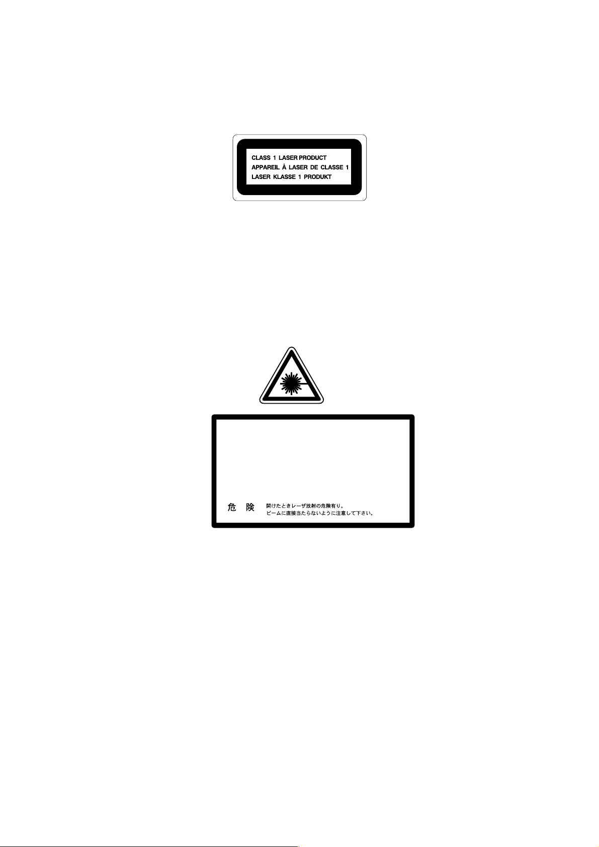
IEC 60825 SPECIFICATION (FOR 220-240 V MODEL ONLY)
This printer is a Class 1 laser product as defined in IEC 60825 specifications. The label shown below
is attached in countries where required.
This printer has a Class 3B Laser Diode which emits invisible laser radiation in the Scanner Unit. The
Scanner Unit should not be opened under any circumstances.
Caution
Use of controls, adjustments or performance of procedures other than those specified in this manual
may result in hazardous radiation exposure.
The following caution label is attached near the laser unit.
5mW
780nm-800nm
DANGERVORSICHT
DANGERPELIGRO-
INVISIBLE LASER RADIATION WHEN OPEN.
AVOID DIRECT EXPOSURE TO BEAM.
UNSICHTBARE LASERSTRAHLUNG, WENN ABDECKUNG
-
GEÖFFNET UND SICHERHEITSVERRIEGELUNG
ÜBERBRÜCKT. NICHT DEM STRAHL AUSSETZEN.
RAYON LASER INVISIBLE LORS DE L’OUVER TURE.
EVITER L’EXPOSITION DIRECTE.
RADIACION LASER INVISIBLE AL ABRIR. EVITAR
LA EXPOSICION DIRECTA AL HAZ.
MAS
For Finland and Sweden
LUOKAN 1 LASERLAITE
KLASS 1 LASER APPARAT
Varoitus! Laitteen käyttäminen muulla kuin tässä käyttöohjeessa mainitulla tavalla saattaa altistaa
käyttäjän turvallisuusluokan 1 ylittävälle näkymättömälle lasersäteilylle.
Varning – Om apparaten används på annat sätt än i denna Bruksanvisning specificerats, kan
användaren utsättas för osynlig laserstrålning, som överskrider gränsen för laserklass 1.
vii
Page 10

SHIPMENT OF THE PRINTER
SAFETY INSTRUCTIONS
SAFETY PRINCIPLE
1) Before starting any operations, read this manual thoroughly. Especially read the safety instructions
in this section carefully and ensure that you understand the contents.
2) Perform all the operations by following the procedures described in this manual. Follow all the
cautions and warnings set out in the procedures and on safety labels affixed to the machine.
Failure to do so may result in human injury or equipment damage.
3) Perform only the procedures explained in this manual. Refrain from opening or touching any
portions that are not related to your required operation(s).
4) Repair and replacement of parts should be performed by trained and qualified persons only.
Operators should not attempt to do such repair or replacement work.
5) It must be appreciated that the above-mentioned cautions and warnings do not cover every
circumstance because it is impossible to evaluate all the conditions of repair situations.
SPECIAL SAFETY INFORMATION
Introductory Information
Cautions and warnings are made clear by them following a ‘Safety Alert Symbol’ or ‘Signal Word’ such
as DANGER, WARNING and CAUTION.
<SAFETY ALERT SYMBOL>
This is the safety alert. When you find this symbol placed on the equipment or marked in this manual,
be aware of the potential of human injuries. Follow the recommended precautions and safety
operation practices.
<Understanding Signal Words>
DANGER is used to indicate the presence of a hazard which will cause severe human injuries or a fatal
accident if the warning is ignored.
WARNING is used to indicate the presence of a hazard or unsafe practices which may cause severe
human injuries or a fatal accident if the warning is ignored.
CAUTION is used to indicate the presence of a hazard or unsafe practices which may cause minor
human injuries if the warning is ignored. CAUTION also calls your attention to safety messages in this
manual.
<Follow Safely Instructions>
Carefully read all the safety messages set out in this manual and also in the safety warning signs
placed on the equipment. In this manual, the safety instructions (safety alert symbols and signal
words) are enclosed in a rectangular enclosure to bring them to your attention. Keep the safety signs
on the equipment in good condition and ensure none are missing or damaged. Replace the safety
signs if unreadable or damaged. Learn how to operate the equipment and how to use the controls
properly. Do not let anyone operate this equipment without following the instructions. Keep the
equipment in proper working condition. Unauthorized modification to the equipment may impair the
function & safety and affect the life of the equipment.
Listed below are the various kinds of “WARNING” messages contained in this manual.
<Caution for the batteries>
There is a danger of explosion if the battery is incorrectly replaced.
Do not replace the battery.
Do not disassemble, recharge or dispose of in fire.
Used battery should be disposed of according to local regulations.
viii
Page 11
HL-3450CN SERVICE MANUAL
WARNING
HAZARDOUS VOLTAGE
May cause serious injuries or fatal accidents. Voltage is now applied from the power
supply of printer. There is a danger of electrical shock if you touch the active area
inside the printer.
Be sure to turn the power supply switch OFF and pull the plug out from the power
outlet before starting maintenance work on the printer.
WARNING
HARMFUL OZONE GAS
Inhalation of an excessive amount of ozone gas may adversely affect the respiratory
organs.
An Ozone Filter is fitted to this printer to reduce the exhausted ozone. This filter
must be replaced with a new filter periodically in accordance with the manual
supplied with the printer.
WARNING
HOT SURFACE
The Fusing Unit reaches a temperature of approx.160°C and adjacent parts are also
very hot.
When you need to change the cleaning pad or remove jammed paper, wait about 20
minutes after opening the paper exit unit to allow the unit to cool down.
CAUTION
ROTATING PARTS
Be aware of the potential danger of various rollers and take care not to get your
fingers or hand caught in the machine, this can cause serious injuries. Note that the
exit roller that ejects the printed paper rotates during printing.
Be careful not to get your hair, fingers, hands, sleeve or necktie caught in the
machine while operating the machine.
ix
Page 12
SHIPMENT OF THE PRINTER
CAUTION
HAZARDOUS POWDER
Toner is a fine powder which can cause a powder explosion if disposed of into a fire.
Under no circumstances dispose of toner into a fire.
CAUTION
HAZARDOUS POWDER
Toner is a fine powder which may cause irritation to the eyes and respiratory organs
if inhaled.
Handle the toner cartridge, waste toner pack and developing unit carefully so as not
to spill the toner.
CAUTION
POWER CORDS & PLUGS
This printer is equipped with a 3-wire power cord fitted with a 3-pronged plug (bipolar plug with grounding) for the user’s safety.
Use these power cords in conjunction with a properly grounded electrical outlet to
avoid an electrical shock.
CAUTION
SAFETY INTERLOCK
The front cover, paper exit unit and transfer unit of this printer have electrical safety
interlocks to turn the power off whenever they are opened. Do not attempt to
circumvent these safety interlocks.
CAUTION
N Do not step on or lean against the media cassette. It may cause the product to tilt
or fall over and result in injuries.
N Do not lean against or apply any excessive force to the media cassette or open
covers, otherwise it may cause the product to tilt or fall over and result in injuries.
x
Page 13
HL-3450CN SERVICE MANUAL
CAUTION
Do not lean against or apply any excessive force to the paper cassette, open cover
of Duplex unit. Otherwise it may cause the product to decline or fall down and result
in the injuries.
xi
Page 14
SHIPMENT OF THE PRINTER
1
2
4 3
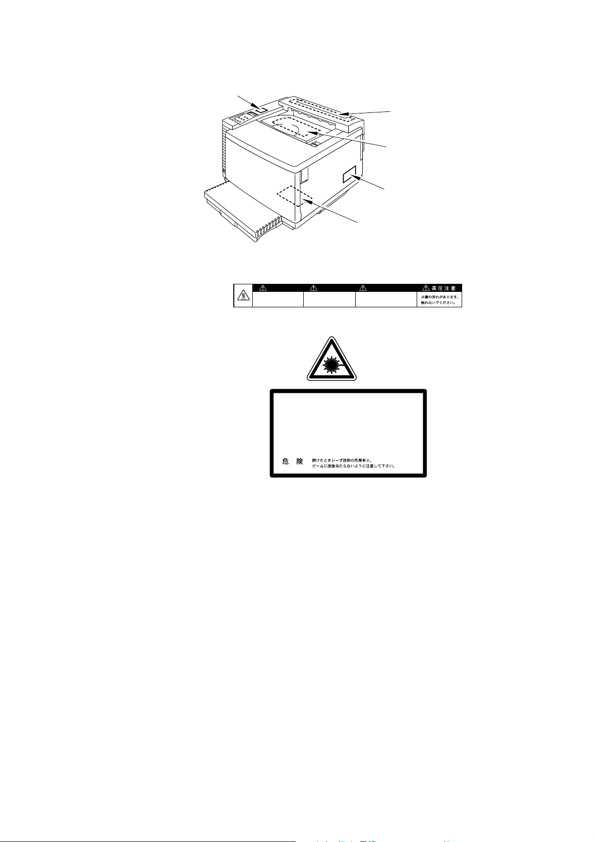
<Label Location>
1. Hot Caution Label
5
WARNING WARNUNG
Hot surface.
Avoid contact.
Heiße oberfiäche.
Bei beseitigung.
AVERTISSEMENT
Surface chaude.
Eviter tout contact.
2. Laser Caution Label
DANGERVORSICHT
DANGERPELIGRO-
5mW
780nm-800nm
INVISIBLE LASER RADIATION WHEN OPEN.
AVOID DIRECT EXPOSURE TO BEAM.
UNSICHTBARE LASERSTRAHLUNG, WENN ABDECKUNG
-
GEÖFFNET UND SICHERHEITSVERRIEGELUNG
ÜBERBRÜCKT. NICHT DEM STRAHL AUSSETZEN.
RAYON LASER INVISIBLE LORS DE L’OUVER TURE.
EVITER L’EXPOSITION DIRECTE.
RADIACION LASER INVISIBLE AL ABRIR. EVITAR
LA EXPOSICION DIRECTA AL HAZ.
MAS
xii
Page 15
HL-3450CN SERVICE MANUAL
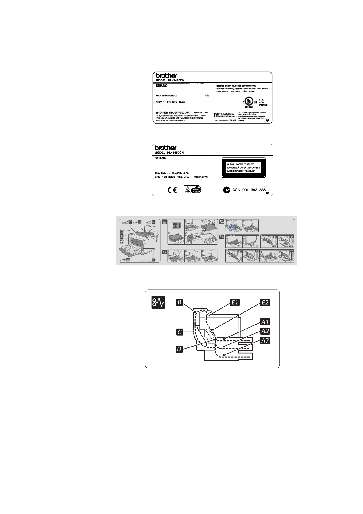
3. Rating Label
4. Operation Label
(For US)
(For Europe)
5. Jam Label
xiii
Page 16
SHIPMENT OF THE PRINTER
SHIPMENT OF THE PRINTER
If for any reason you must ship the printer, carefully package the printer to avoid any damage during
transit. It is recommended that you save and use the original packaging. The printer should also be
adequately insured with the carrier.
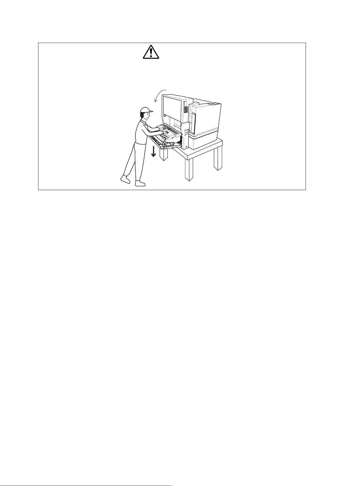
CAUTION
N When shipping the printer, remove the toner cartridges, the OPC belt cartridge
and the waste toner pack from the printer to prevent toner spill in the printer or
damage of the toner cartridge and the OPC belt cartridge.
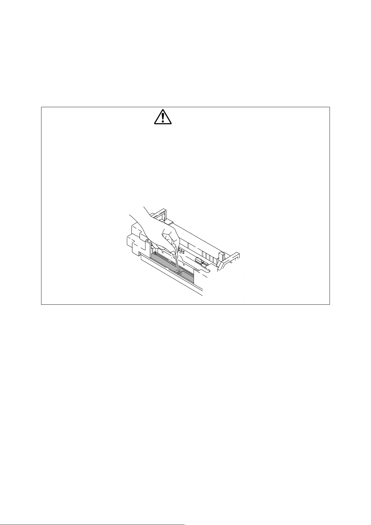
N When shipping the printer, remove the oil bottle and the fuser cleaner from the
fusing unit. After removing the oil bottle, be sure to remove the oil remaining in the
fusing unit with the supplied syringe. Failure to do so will cause severe damage to
the printer.
xiv
Page 17

CHAPTER 1
PRODUCT OUTLINE
HL-3450CN SERVICE MANUAL
Page 18

CHAPTER 1 PRODUCT OUTLINE
1-2
CONTENTS
CHAPTER 1 PRODUCT OUTLINE .....................................................1-3
1. FEATURES..........................................................................................................1-3
2. PARTS NAMES & FUNCTIONS..........................................................................1-6
3. INTERNAL STRUCTURE....................................................................................1-8
4. DESCRIPTION OF CONTROL PANEL ...............................................................1-9
4.1 Video Controller Mode.................................................................................................................1-9
4.2 Engine Controller Mode...............................................................................................................1-9
Page 19

1-3
CHAPTER 1 PRODUCT OUTLINE
1. FEATURES
This printer has the following features:
2400 x 600 dpi Class Resolution
The printer prints pages with a resolution of 600 dots per inch (dpi) as default. It also
provides higher quality printout which is the equivalent of 2400 x 600 dpi resolution when
using High Resolution Control (HRC) or Color Advanced Photoscale Technology (CAPT).
High Speed Color Laser Printing
The printer allows crisp printing in 24 bit brilliant color. The printer prints at a speed of 24
pages per minute in monochrome mode and 6 pages per minute in full color mode when
printing A4 or Letter size paper in Landscape orientation. The controller utilizes a high speed
32-bit RISC microprocessor and special hardware chips, which provides a very fast
processing speed.
HL-3450CN SERVICE MANUAL
High Resolution Control (HRC)
The high resolution control (HRC) technology provides clear and crisp printouts and improves
even the 600 dpi resolution. This mode is effective when printing text data.
Color Advanced Photoscale Technology (CAPT)
®
The printer can print graphics in 256 shades for each color in HP
color printer PCL5C™ and
BR-Script 3 emulations, producing nearly photographic quality. This mode is effective when
printing photographic images.
Maintenance-Free & Economical Tone r Cartridge
A toner cartridge can print up to 14,000 (Black) and 8,500 (Cyan, Magenta and Yellow)
single-sided pages at 5% coverage. The one piece, easy-to-replace toner cartridges do not
require difficult maintenance.
Universal Media Cassette
This printer loads paper automatically from the media cassette. Since the media cassette is
a universal type, a number of different sizes of paper can be used. Even envelopes can be
loaded from the media cassette.
Three Interfaces
This printer has a high speed, bi-directional parallel interface, USB and Ethernet
10/100BaseTX.
If your application software supports the bi-directional parallel interface, you can monitor the
printer status. It is fully compatible with the industry-standard bi-directional parallel interface.
The Brother network board (NC-4100h) is factory installed in the HL-3450CN, which enables
you to use this printer in the TCP/IP, IPS/SPX, Apple Talk, DLC/LLC, Banyan VINES, DEC
LAT and NetBEUI environments. Also, many useful utilities, such as BRAdmin Professional
for the administrator and Brother network printing software, are included in the CD-ROM
supplied with the HL-3450CN printer. For setup, see the Network User’s Guide.
Page 20

CHAPTER 1 PRODUCT OUTLINE
1-4
Automatic Interface Selection
The printer can automatically select the bi-directional parallel, USB, or Ethernet 10/100 Base
TX depending on the interface port through which it receives data. With this feature, the
printer can be connected to more than one computer.
Five Emulation Modes
®
The printer can emulate Hewlett-Packard
mode), PostScript
®
3 language emulation (Brother BR-Script 3) printers, the industry-
standard HP-GL™ plotter as well as EPSON
Color PCL® 5C language (PCL6® in monochrome
®
FX-850™, and IBM® Proprinter XL® printers (in
monochrome mode). It is possible to print with all application programs that support one of
these printers.
Automatic Emulation Selection
The printer can automatically select the printer emulation mode depending on the print
commands it receives from the computer software. With this feature, many users can share
the printer on a network.
Data Compression Technology
The printer can internally compress the received graphics and font data in its memory so that
it can print larger graphics and more fonts without additional memory.
Various Fonts
The printer has 66 scalable and 12 bitmapped fonts. The fonts that can be used will vary
according to the selected emulation mode.
In PCL mode, you can also print the 13 kinds of bar codes listed below. In BR-Script mode,
the printer has 165 scalable fonts.
< Bar Code Printing >
This printer can print the following 13 types of bar codes:
x
Code 39
x
Code 128
x
Interleaved 2 of 5
x
Codabar
x
ISBN (EAN)
x
ISBN (UPC-E)
x
UPC-A
x
UPC-E
x
EAN-8
x
EAN-13
x
EAN-128
x
FIM (US-PostNet)
x
Post Net
(US-PostNet)
CCITT G3/G4
Since the printer supports the CCITT G3/G4 format in addition to HP-compatible formats, it
can quickly receive and print data compressed in this format.
Lock Panel
If the panel button settings have been changed, the printer may not work as expected. It is
possible for the administrator of the printer to lock the settings to prevent changes from being
made.
Power Save Mode
The printer has a power save mode. As laser printers consume power to keep the fixing
assembly at a high temperature, this feature can save electricity when the printer is on but
not being used. The factory setting of the Power Save mode is ON so that it complies with
the new EPA Energy Star new specification.
Page 21

HL-3450CN SERVICE MANUAL
1-5
Toner Save Mode
The printer has an economical toner save mode. This mode allows you to reduce the printer
running cost substantially in addition to the improved life expectancy of the toner cartridge.
Reprint Function
A touch of a panel button allows reprinting of the last print job without sending the data again
from the computer. When there is not enough memory to print the last complete job out, the
last print page can be reprinted. Data can be stored in an IDE HDD that can be optionally
installed. It can be reprinted by selecting a document from the control panel or the browser.
When the private print driver is selected, Secure Printing can be executed which allows you
to print only when a password is entered.
Saving User Settings
It is possible to operate the printer differently from other users with the panel button settings.
One set of user settings can be stored.
*PANTONE
®
Calibrated
There are many variables in process reproduction of colors generated by the HL-3450CN,
any one of which may affect the quality of the PANTONE Color simulation, including;
x
Type of paper used
x
Type of toner used
x
Effective final resolution
x
Dot structure/halftones
For optimal results, it is recommended that the following materials and settings are used.
1) NEUSIEDLER color copy paper
2) Brother Toner Cartridges TN-02 BK/C/M/Y
3) 600 x 600 dpi resolution
Page 22
CHAPTER 1 PRODUCT OUTLINE
1-6
1
3
M
6
8
7
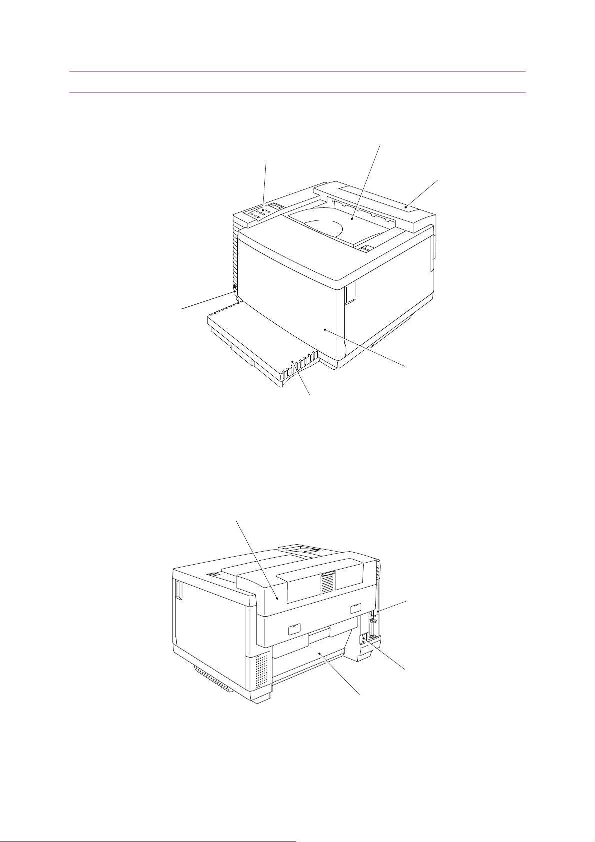
2. PARTS NAMES & FUNCTIONS
<Front View>
5. Power button
. Upper cover
2. Control panel
4. Top cover
(Paper Exit Unit)
<Rear View>
. Front cover
edia cassette
Fig. 1-1
Paper exit unit
. Controller box
. Power inlet
. Rear access cover
Fig. 1-2
Page 23

1-7
No. Part Name Outline of Functions
HL-3450CN SERVICE MANUAL
1 Upper cover
2 Control panel
3 Front cover
To act as an upper enclosure and also as a
paper tray for printed paper.
To display the status of printer operations and
control the printer directly.
To act as a front enclosure, opened when
replacing a toner cartridge or waste toner pack.
To exit the printed paper onto the upper cover,
Top cover (Paper exit
4
unit)
acting also as part of the paper tray for printed
paper. To be opened when replacing an OPC
belt cartridge or Drum cleaner.
5 Power button
To operate power-on and off to the printer.
(Push for On/Off operation)
6 Power inlet To connect a power supply cable.
7 Re ar access cover
8 Controller box
To act as a rear enclosure, opened when
clearing an internal jam or doing maintenance
work.
Space where the main (video controller) PCB is
installed.
Page 24
CHAPTER 1 PRODUCT OUTLINE
1-8
2
1
(
1
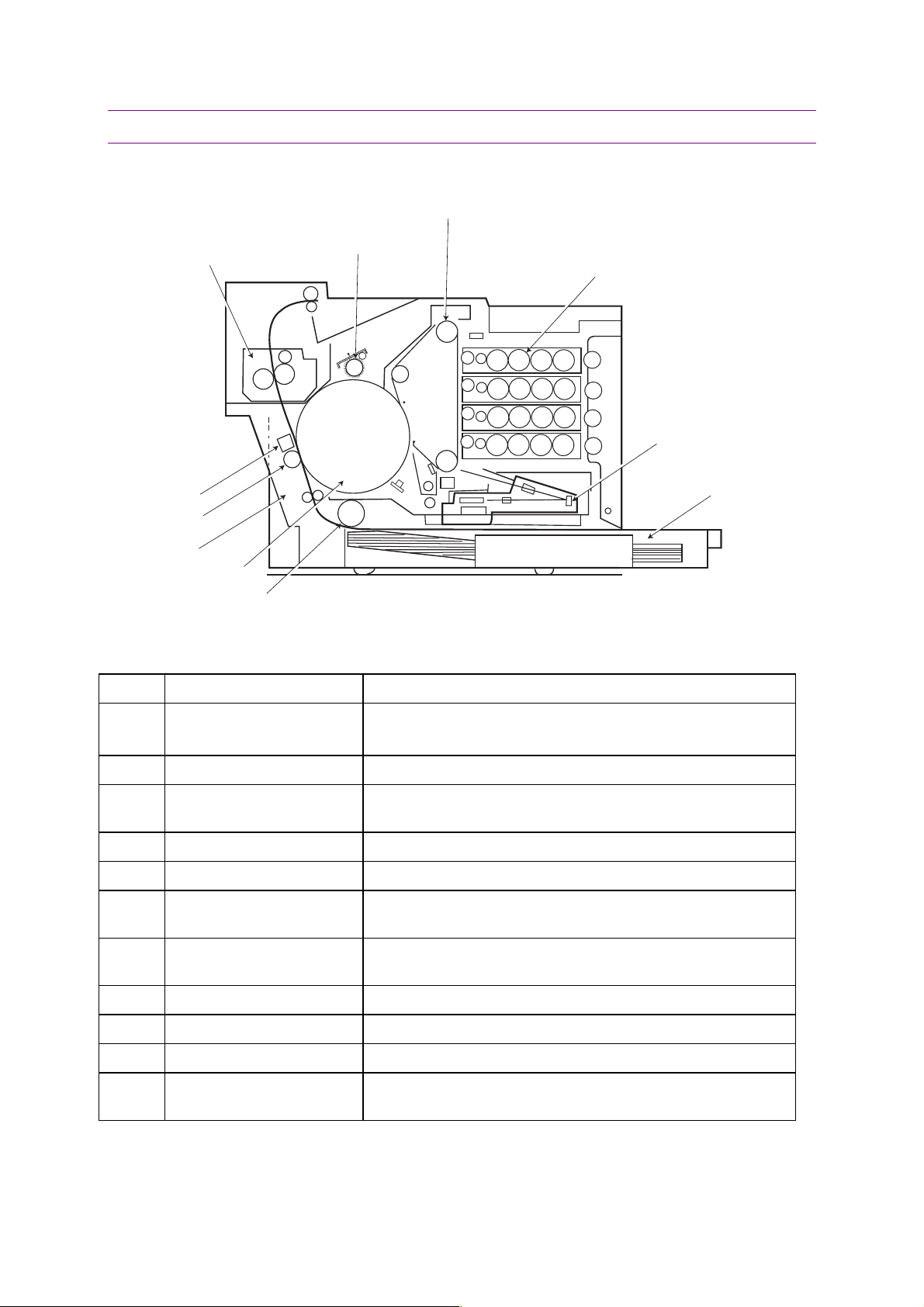
3. INTERNAL STRUCTURE
<Cross Sectional View >
. OPC Belt Cartridge
4. Fusing Unit
3. Drum Cleaner
K
Y
M
C
7. Paper Discharger
8. Transfer Roller
5. Transfer Unit
6. Transfer Drum
10. Paper Pick-up
Roller
Fig. 1-3
No. Components Name Outline of Functions
. Toner Cartridge
K, Y, M, C)
1. Laser Unit
9. Media Cassette
1 Toner Cartridge
Contain the toner (K, Y, M, C) for developing.
Each toner cartridge (K, Y, M, C) is independent.
2 OPC Belt Cartridge Forms images and includes the OPC belt.
3 Drum Cleaner
Cleans and collects waste toner adhering to the transfer
drum.
4 Fusing Unit Fixes by heat and pressure the toner image onto the paper.
5 Transfer unit Transfers toner images from the transfer drum to the paper.
6 Transfer Drum
7 Paper Discharger
Forms color images, combining the toner images from the
OPC belt on the drum.
Emits a corona charge for separating the paper from the
transfer drum.
8 Transfer Roller Transfers the toner image on the transfer drum to the paper.
9 Media Cassette Feeds paper automatically.
10 Paper Pick-up Roller Feeds paper automatically from the media cassette.
11 Laser Unit
Generates a modulated laser beam and scans the OPC belt
to produce the image.
Page 25

1-9
4. DESCRIPTION OF CONTROL PANEL
The printer control panel provides control of the printer including test printing, maintenance
operations performed by the video controller and also the ones which are performed by the
engine controller.
The Video Controller Mode and the Engine Controller Mode have some common functions.
Under normal circumstances the functions in the Video controller mode will be used. Refer to
CHAPTER 5 for further information.
4.1 Video Controller Mode
The printer goes into the Video Controller Mode when the power is turned on by pressing the
power button.
The Video Controller Mode supplies the general test printing and setting functions and some
of the maintenance operations. If further engine settings are required, use the Engine
Controller Mode.
HL-3450CN SERVICE MANUAL
4.2 Engine Controller Mode
The printer goes into the Engine Controller Mode when power is turned on by pressing the
power button at the same time as holding down the
(Refer to Fig.1-4.)
NOTE:
This mode provides unique control panel display and operation functions which are
completely different from the ones described on the actual control panel labels or in the
user’s guide. Refer to CHAPTER 5 for detailed information.
Secure print, Back
and
Set
buttons.
Page 26
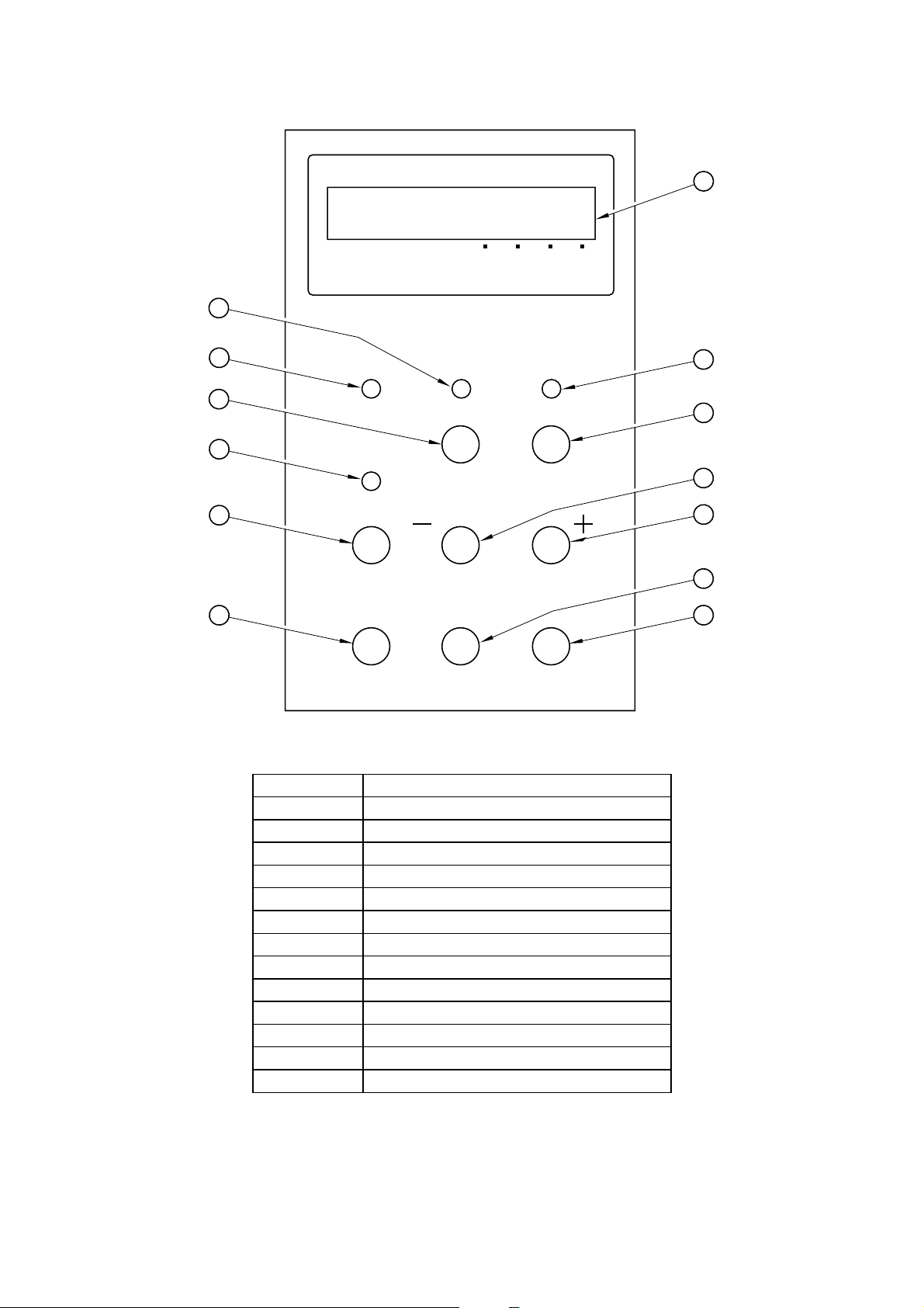
CHAPTER 1 PRODUCT OUTLINE
1
3
1
KCMY
2
Power DataReady
4
5
6
7
8
11
No. LED / Button Name
1 LCD: 16 character by 2 lines
2 Power LED
3 Ready LED
4 Data LED
5 Go button
6 Job Cancel button
7 Alarm LED
8 Secure Print button
9 - button
10 + button
11 Reprint button
12 Back button
13 Set button
Alarm
Secure
Print
Reprint
Go
Back
Fig. 1-4
Menu
Job
Cancel
Set
9
10
12
13
-10
Page 27

CHAPTER 2
SPECIFICATIONS
HL-3450CN SERVICE MANUAL
Page 28

CHAPTER 2 SPECIFICATIONS
2-2
CONTENTS
CHAPTER 2 SPECIFICATIONS..........................................................2-3
1. RATING ..............................................................................................................2-3
2. GENERAL SPECIFICATIONS............................................................................2-4
2.1 Printing .......................................................................................................................................2-4
2.2 Functions....................................................................................................................................2-4
2.3 Electrical and Mechanical...........................................................................................................2-5
2.4 Paper..........................................................................................................................................2-6
2.4.1 Printable media....................................................................................................................2-6
2.4.2 Media cassette capacity ......................................................................................................2-8
2.4.3 Printed output.......................................................................................................................2-8
2.5 Printing Area...............................................................................................................................2-8
2.5.1 Effective printable area........................................................................................................2-8
2.5.2 Print guarantee area..........................................................................................................2-10
3. ENVIRONMENTAL CONDITIONS.....................................................................2-11
3.1 Ambient Temperature / Humidity / Altitude...............................................................................2-11
Page 29
CHAPTER 2 SPECIFICATIONS
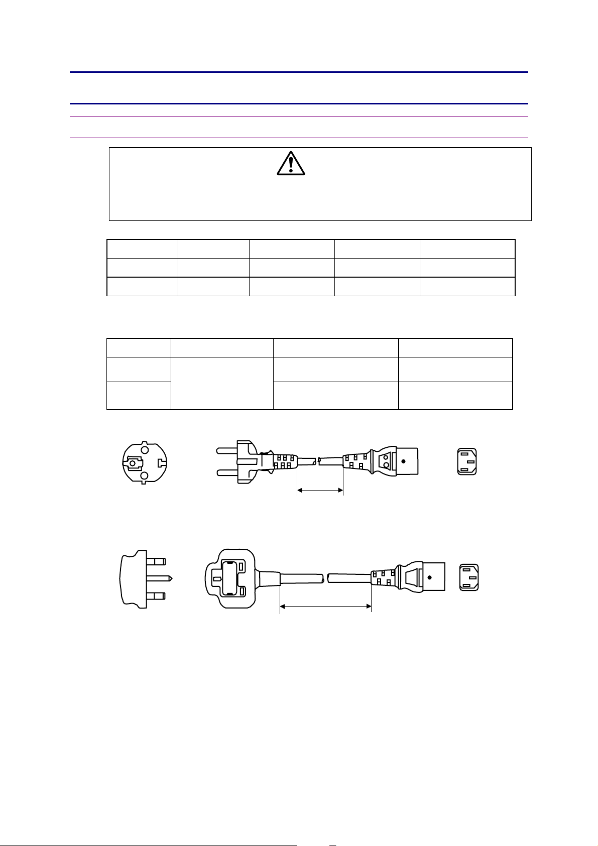
1. RATING
HL-3450CN SERVICE MANUAL
WARNING
Use the power supply cable supplied with the printer, or a similar cable complying
with the following specification (3-wire power cable with ground).
Use of an “out of specification” cable may result in an electric shock.
Destination Voltage (V) Frequency (Hz) Input Current (A) Power Cord (Piece)
US / Canada 120 50/60 11 1
Europe 220 - 240 50/60 6 1 *
* For European models, the power supply cable depends on the country as follows;
Figure Rating Approval Agency Applicable Area
A
B
Figure A: For Europe (Sample)
250VAC, 6A
VDE, DEMKO, SEV Europe (Continent)
BS UK
2.5m
Figure B: For UK
2.5m
NOTE:
For details of other power supply cables, refer to the parts reference list.
** For rating labels, refer to ‘Safety Instruction’ on Page viii.
2-3
Page 30

CHAPTER 2 SPECIFICATIONS
2. GENERAL SPECIFICATIONS
2.1. Printing
Print method Electro photography by semiconductor laser beam scanning
Laser Wavelength: 780nm
Output: 5mW max.
Resolution 600 x 600 dots per inch (Fine)
2400 x 600 dots per inch (using HRC and CAPT)
Print speed Monochrome mode: 24 page/minute
Full color mode: 6 page/minute
(when printing A4/Letter-size paper in Landscape orientation)
Monochrome mode: 12 page/minute
Full color mode: 3 page/minute
(when printing A3/Ledger-size paper in Portrait orientation)
Warm-up Max. 210 seconds at 20°C (68°F)
First print Monochrome mode: 19 seconds or less
Full color mode: 34 seconds or less
(when loading A4/Letter-size plain paper in Landscape orientation by
Print media Toner in a single-color single-component cartridge.
Life Expectancy: 14,000 single-sided pages/cartridge (Black)
8,500 single-sided pages/cartridge (C/M/Y)
(when printing on A4/Letter-size paper with 5% coverage)
Resident printer fonts <HP PCL, EPSON FX-850, and IBM Proprinter XL modes>
66 scalable fonts and 12 bitmapped fonts,11 bar codes
<BR-Script 3 mode>
165 scalable fonts
(The resolution can be enhanced to 2400dpi class by using Brother
exclusive HRC (High Resolution Control) and CAPT (Color Advanced
Photoscale Technology).)
face down print delivery from standard upper cassette feed)
2.2. Functions
CPU Toshiba TMPR4955-266 (TX4955-266MHz)
Emulation Automatic emulation selection
Interface Automatic interface selection among the bi-directional parallel,
RAM 64 Mbytes
(Expandable up to 384Mbytes with DIMMs)
The standard memory fitted can vary depending on the printer model
HDD option 2.5 inch IDE HDD
Compact Flash 1 card slot: Compact Flash Type II
Control panel 8 buttons, 4 LEDs and a 16-column x 2 lines liquid crystal display
Diagnostics Self-diagnostic program
x
HP Color Printer (PCL5C) including HP LaserJet 4+ (PCL5e) and
HP LaserJet 5 (PCL6 monochrome)
x
BR-Script 3 (Adobe PostScript 3 compatible)
x
HP-GL
x
EPSON FX-850
x
IBM Proprinter XL
Universal Serial Bus (USB) and Ethernet 10/100 Base TX.
and country.
2-4
Page 31

2-5
2.3. Electrical and Mechanical
Power source U.S.A. and Canada: AC 120V, 50/60Hz
Europe and Australia: AC 220 to 240V, 50/60Hz
Power consumption Printing (peak*): 1350W or less
Printing (average): 600W or less
Standing by (peak*): 1350W or less
Standing by (average): 200W or less
Sleep: 30W or less
Noise: Printing: 55dB A or less
Standing by: 48dB A or less
Temperature: Operating: 10 to 32.5°C (50 to 90.5°F)
Non operating: 5 to 35°C (41 to 95°F)
Storage: 0 to 35°C (38 to 95°F)
Humidity: Operating: 20 to 80% (non condensation)
Storage: 10 to 90% (non condensation)
HL-3450CN SERVICE MANUAL
Dimensions: 615 x 540 x 420 mm (24.2 x 21.3 x 16.5 inches)
(W x D x H) 615 x 620 x 610 mm (24.2 x 24.4 x 24.0 inches)
with the Duplex Unit and one optional lower tray unit fitted
615 x 620 x 750 mm (24.2 x 24.4 x 30.6 inches)
with the Duplex Unit and two optional lower tray units fitted
Weight: Approx. 46kg (101lbs.)
Approx. 54kg (119lbs.) including consumables*
*Consumables are defined as:
Belt cartridge, Toner cartridge (Y, M, C, K), Fuser oil bottle,
Fuser cleaning roller, Waste toner Pack
Optional Units:
x
Lower Tray Unit: Approx. 11kg (24lbs.)
x
Duplex Unit: Approx. 12kg (26lbs.)
x
Standard Media Cassette: Approx. 2.1kg (4.6lbs.)
x
Lower Tray Unit Media Cassette: Approx. 2.7kg (6.0lbs.)
*NOTE:
x
The peak figure of power consumption is worked out when the halogen heater lamp is
turned ON.
x
The peak figure of power consumption is worked out excluding inrush current value.
x
The peak figure of power consumption is a reference value and should be used internally
at Brother offices only.
x
The power consumption figure quoted for sleep mode is when the fan has stopped.
Page 32

CHAPTER 2 SPECIFICATIONS
2.4. Paper
The standard media cassette (upper cassette) is supplied with the printer. The optional lower
tray unit and the optional A4/Letter cassette can also be installed.
NOTE:
The standard upper cassettes and the optional A4/Letter cassette are interchangeable
between the upper and the lower feeder.
2.4.1 Printable media
(1) Type & size
Paper source Paper type Paper Size
Standard upper cassette
Plain paper A3, B4, A4, Ledger, Executive, Legal,
Letter, B5 (ISO/JIS), 330x483mm
(13”x19”)
Envelope COM10, DL,
Transparency A4, Letter
Label A4, Letter
Other size width 210-330mm (8.2”-12.9”)
length 176-483mm (6.9”-18.8”)
Optional lower cassette Plain paper A3, B4, A4, B5 (ISO/JIS), Legal, Ledger,
Letter
Optional A4/Letter cassette Plain paper A4, Letter, B5 (ISO/JIS), Executive
Envelope: COM10, DL
Transparency A4, Letter
Label A4, Letter
Other size: width 210-297mm (8.2”-11.7”)
length 176-297mm (6.9”-11.7”)
(2) Paper weight specifications
Paper cassette Optional lower tray Optional duplex unit
Normal paper
60 to 90 g/m
2
m
m
(16 to 24 lbs)
Thick stock
90 to 160 g/m
(24 to 43 lbs)
2
90 to 105 g/m
(24 to 28 lbs)
2-6
2
Page 33

2-7
(3) Recommended paper specifications
!
Item Description
Basis Weight (g/m2) 82 ± 5
Thickness (µ m) 95 ± 6
Smoothness (Bekk) (seconds) 90 ± 20
Stiffness (Clark) 100 ± 15
Brightness (%) 85 ± 2
10
10
Surface Resistance (:)
Grain Direction Long
Measurement Condition: 17.5 ~ 27.0°C, 50 ~ 70%RH
~ 1011
HL-3450CN SERVICE MANUAL
CAUTION:
When you are choosing print media, be sure to it is designed for use with a laser printer and
load the media cassette correctly. Also follow the information given below to prevent any
paper jams, print quality problems or printer damage;
<Paper type to avoid>
x
Highly textured paper.
x
Smooth or shiny paper.
x
Paper that is coated or has a chemical finish.
x
Damaged, wrinkled or pre-folded paper.
x
Paper exceeding the recommend weight specification in the manual.
x
Paper with tabs and staples.
x
Letterheads using low temperature dyes or thermography.
x
Multipart or carbonless paper.
<Envelopes type to avoid>
x
Envelopes constructed with a paper with a weight that exceeds the paper weight
specifications for the printer.
x
Poorly manufactured envelopes with edges that are not straight or consistently square.
x
Envelopes with ‘baggy’ construction of folds that are not sharply creased.
x
Envelopes with transparent windows, holes, cutouts or perforations.
x
Envelopes with clasps, snaps or tie strings.
x
Envelopes made with smooth or shiny paper.
x
Envelopes that are rough, highly textured, or deeply embossed.
x
Envelopes that do not lie flat or that are curled, wrinkled, or irregularly shaped.
x
Envelopes having an open flap with an adhesive that seals the envelope.
<Transparencies / labels type to avoid>
x
Transparencies / labels that cannot withstand a temperature of 200 degrees centigrade
(392 degrees Fahrenheit) for a period of 0.1 seconds.
NOTE:
Keep the paper sealed in the bag as supplied and do not open the bag until the paper is
required for use.
Page 34

CHAPTER 2 SPECIFICATIONS
2.4.2 Media cassette capacity
Maximum load height: 27mm (1.06 inches)
x
Plain paper: 250 sheets of 75g/m
x
Envelopes : 15 sheets
x
Transparency: 50 sheets
x
Label: 80 sheets
2.4.3 Printed output
(1) Capacity
250 sheets of 75g/m
(2) Delivery
Face-down print delivery
Note: Face down: Delivers the printed side of the paper downwards.
2
(20lb) paper for the standard/optional A4/Letter
cassette
500 sheets of 75g/m
2
(20lb) paper (plain paper stacked in the output tray)
2
(20lb) for the optional lower cassette
2.5 Printing Area
2.5.1 Effective printable area
The effective printing area means the area within which the printing of all the data received
without any omissions can be guaranteed. (Refer to Table 2-1 for details.)
F
E
B
D
A
CE
F
Fig. 2-1
2-8
Page 35

HL-3450CN SERVICE MANUAL
2-9
Table 2-1: Effective Printing Areas
Size A B C D E F
A 4
Letter
Legal
B 5 (JIS)
B 5 (ISO)
Executive
COM-10
D L
13x19 330mm
A 3 297mm
B 4 257mm
Ledger 279.4mm
210.0mm
8.27”
(2,480 dots)
215.9mm
8.5”
(2,550 dots)
215.9mm
8.5”
(2,550 dots)
182.0mm
7.16”
(2,149 dots)
176.0mm
6.93”
(2,078 dots)
184.2mm
7.25”
(2,175 dots)
104.8mm
4.125”
(1,237 dots)
110.1mm
4.33”
(1,299 dots)
13”
(3,900 dots)
11.7”
(3,507 dots)
10.1”
(3,035 dots)
8.5”
(3,300 dots)
297.0mm
11.69”
(3,507 dots)
279.4mm
11.0”
(3,300 dots)
355.6mm
14.0”
(4,200 dots)
257.0mm
10.12”
(3,035 dots)
250.0mm
9.84”
(2,952 dots)
266.7mm
10.5”
(3,150 dots)
241.3mm
9.5”
(2,850 dots)
221mm
8.66”
(2,598 dots)
482.6mm
19”
(5,700 dots)
420mm
16.5”
(4,960 dots)
364mm
14.3”
(4,298 dots)
432mm
14”
(5,100 dots)
203.2mm
8.0”
(2,400 dots)
207.44mm
8.16”
(2,450 dots)
207.44mm
8.16”
(2,450 dots)
173.54mm
6.82”
(2,049 dots)
167.54mm
6.59”
(1,978 dots)
175.74mm
6.91”
(2,075 dots)
96.34mm
3.785”
(1,137 dots)
101.64mm
3.99”
(1,199 dots)
306.5mm
12.1”
(3,620 dots)
288.5mm
11.4”
(3,407 dots)
248.9mm
9.8”
(2,935 dots)
270.9mm
10.7”
(3,200 dots)
288.5mm
11.36”
(3,407 dots)
271.0mm
10.67”
(3,200 dots)
347.1mm
13.67”
(4,100 dots)
248.5mm
9.78”
(2,935 dots)
241.5mm
9.5”
(2,852 dots)
258.3mm
10.17”
(3,050 dots)
232.8mm
9.16”
(2,750 dots)
211.5mm
8.33”
(2,498 dots)
475.8mm
18.7”
(5,620 dots)
411.5mm
16.2”
(4,860 dots)
355.4mm
14”
(4,198 dots)
423.3mm
16.7”
(5,000 dots)
3.4mm
0.13”
(40 dots)
4.23mm
0.17”
(50 dots)
Ç
Ç
Ç
Ç
Ç
Ç
11.85mm
0.47”
(140 dots)
4.23mm
0.17”
(50 dots)
Ç
Ç
4.23mm
0.17”
(50 dots)
Ç
Ç
Ç
Ç
Ç
Ç
Ç
Ç
Ç
Ç
Ç
NOTE:
x
The paper sizes indicated here should conform to the nominal dimensions specified by
JIS.
x
A4 paper must accommodate 80 characters printed in pica pitch (203.2 mm).
x
The dot size is based on 300 dpi resolution.
x
Organizer is not supported by any printer emulation (command).
Page 36

CHAPTER 2 SPECIFICATIONS
P
O
P
O
3
5
N
a
N
a
N
a
4
4
#
D
2.5.2 Print guarantee area
<Plain paper>
3mm
5mm
Print
guarantee
area
Fig. 2-2
mm
on printable
rea
on guarantee
rea
mm
mm
mm
aper: 5mm
ther: 10mm
aper: 4mm
ther: 10mm
<Envelope>
42mm
16mm
3mm
4mm
Non guarantee
area
#10: 68mm
DL: 40mm
on printable
rea
Print guarantee
area
4mm
10: 68mm
L: 40mm
Fig. 2-3
2-10
Page 37

2
3. ENVIRONMENTAL CONDITIONS
R
1
5
3.1 Ambient Temperature / Humidity / Altitude
(1) Under Operational conditions: 10.0 a 32.5qC (50 ~ 90.5qF), 20 a 80%RH (See the
figure below)
80
70
HL-3450CN SERVICE MANUAL
60
50
ecommended Condition;
27.0qC
a
7.5
0 a 70%RH
40
20
Ambient Humidity (%RH)
100 17.5 20 27 30 32.5 40
Ambient Temperature ( )
C
(2) Under Non Operational conditions: 5.0 a 35.0qC (41 ~ 95qF), 10 a 80%RH (See the
figure below.)
80
60
40
30
Ambient Humidity (%RH)
20
10
5
10020303540
Ambient Temperature( )
C
-11
Page 38

CHAPTER 2 SPECIFICATIONS
(3) Storage and transportation environment of printer
The following defines the storage and transportation environment of printers that have been
packed according to Brother specification. However, this section does not cover the OPC
belt cartridge, toner cartridges and developer cartridges.
In particular, since consumables such as the toner cartridges and OPC belt are individually
packaged, the following environmental conditions should be respected. During
transportation, strictly refrain from leaving the goods on the ground or under the sun.
Temperature
Humidity
Normal
Conditions
Severe
Conditions
0qC a 35qC (32qF a 95qF)
High Temperature: 35qC a 40qC (95qF a 104qF)
Low Temperature: -10qC a 0qC (14qF a 32qF)
10% a 90%RH
Period of Storage One Year
Other No condensation
Atmosphere
613 a 1,067hpa (460 a 800mmHg)
The period under the severe conditions should not be continuous, and is assumed as an
accumulation of intermittent time. However, an individual period of intermittent time under
severe conditions should not be allowed to exceed 48 hours.
NOTE:
Normal conditions should occupy more than 90% of total storage period.
Severe conditions should be less than 10% of total storage period.
2-12
Page 39

CHAPTER 3
INSTALLATION
Page 40

CHAPTER 3 INSTALLATION
3-2
CONTENTS
CHAPTER 3 INSTALLATION .........................................................3-3
1. CONDITIONS REQUIRED FOR INSTALLATION...........................................3-3
1.1. Environmental Conditions.....................................................................................................3-3
1.2. Basic Layout of Printer Set-up Location ...............................................................................3-3
2. UNPACKING...................................................................................................3-5
2.1 Unpacking of Printer..............................................................................................................3-5
2.2 Unpack the Starter Kit ...........................................................................................................3-7
3. INSTALLATION WORK ..................................................................................3-8
3.1 Install the Oil Bottle and Fuser Cleaner.................................................................................3-8
3.2 Install the OPC Belt Cartridge ...............................................................................................3-9
3.3 Install the Toner Cartridge into the Printer...........................................................................3-11
3.4 Install the Media Cassette and Adaptor...............................................................................3-12
3.4.1 Install the media cassette .............................................................................................3-12
3.4.2 Install the envelope adaptor..........................................................................................3-13
3.5 Test Print.............................................................................................................................3-14
Page 41

3-3
CHAPTER 3 INSTALLATION
1. CONDITIONS REQUIRED FOR INSTALLATION
Any Laser beam printer is likely to be influenced by the environment of the set-up location. If
the printer is set-up in an inappropriate location, the printer may not perform as expected.
Therefore, the following factors should be taken into consideration before deciding where to
set-up the printer.
1.1. Environmental Conditions
The printer should not be set up in the locations referred to in the following items (1) through
(8) which specify inappropriate locations for set-up.
(1) Where it is likely to receive direct sunlight or similar light. (For example, next to a
window)
(2) Where it is likely to suffer a big difference in temperature and humidity between the
maximum and minimum levels. (Normal operation environment is within 10qC a 32.5qC,
20 a 80%RH and without any condensation.)
HL-3450CN SERVICE MANUAL
(3) Where it is likely to be in a draft of cold air from an air-conditioner or warm air from a
heater, or to receive direct radiant heat.
(4) Where it is likely to be excessively dusty or be subject to corrosive gases such as
ammonia.
(5) Where it is likely that an ultrasonic humidifier will be used.
(6) Where it is likely to have poor ventilation.
(7) Where it is likely to have unstable conditions such as when the set-up table is not strong
enough.
(8) Where it is likely to be tilted (angle from the horizontal should not be greater than r1q).
1.2. Basic Layout of Printer Set-up Location
CAUTION
In the case when the printer is set on a table, confirm that the media cassette does not to
protrude out beyond the edge of the table.
x
Any protrusion of the media cassette may catch a passersby and result in damage to the
printer.
x
Protrusion of the media cassette may cause the printer to tilt or fall over if the operator
leans against or applies excessive force to the media cassette, which may cause injuries.
Page 42

CHAPTER 3 INSTALLATION
3-4
Fig.3-1 shows the basic layout of the printer set-up location that is suitable for smooth
operation and maintenance of the printer.
Table
20cm (8")
Paper Exit Side
80cm (32")
50cm (20")
20cm (8")
16cm
(6.4")
70cm
(28")
70cm
(28")
Front Side
10cm (4")
Fig. 3-1
x
A space in front of the printer of 70cm is necessary to open the front cover.
x
A space at back of the printer of 20cm is necessary to open / close the rear access cover.
x
The space on both sides of the printer of 10cm is necessary for general access.
Page 43

3-5
2. UNPACKING
The package containing a printer weighs approximately 66kg (145lbs), so it is too heavy
x
for one person to carry. It needs two adults or more to move the printer. Since the printer
is a precision machine, make sure that it is carried slowly with care so that no impact
occurs to the printer while moving it.
Do not attempt to lift a printer when it is covered by the polyethylene bag because it is
x
slippery and may result in damage and injury if dropped.
2.1 Unpacking the Printer
Refer to Fig.3-2 on the next page.
1) Cut the two bands from around the packing carton.
2) Remove the binding tape from the top of the package.
3) Open the top of the package and take the ST packing set out.
HL-3450CN SERVICE MANUAL
WARNING
4) Remove the upper packing (4 locations).
5) Take the customisation kit** out of the box.
6) Take the power cable out of the box. (for US / Canada only).
7) Open up the polyethylene bag enclosing the printer and remove it.
8) Remove the silica gel.
9) Lift up and set up the printer in a suitable location using at least two persons.
** For USA/Canada, the kit contains the use’s guide and printer driver disks.
For other countries, the kit contains the use’s guide, printer driver disks and the
powercable.
Page 44

CHAPTER 3 INSTALLATION
3-6
STARTER KIT
(ST PACKING SET 3 (B))
STARTER PACKING
SLEEVE
STARTER KIT PACKING (U)
Media cassette
OUTER BOX
Toner cartridges
STARTER KIT PACKING (M)
OPC belt cartridge
Oil bottle
L-SHAPED
PAPER SUPPORT
Toner cartridges
Fuser cleaner
L-SHAPED
PAPER SUPPORT
BASE SET 3 (B)
SILICA GEL
Power cable
POLYETHYLENE
BAG (EN)
PALLET 3 (B)
STARTER KIT
PACKING (L)
BAND
SHIPPING TAPE
TAPE
PROTECTIVE
PACKING
Fig. 3-2
Page 45

HL-3450CN SERVICE MANUAL
3-7
Y
M
C
K
2.2 Unpack the Starter Kit
<Unpacking Procedure>
1) Open the vinyl bag and slide off the cardboard sleeve covering the starter kit.
2) Confirm all of the following parts are inside the starter kit packing box.
No. Kit Name Appearance Quantity
Toner Cartridge (Y, M,
1
C, K)
(Yellow)
(Magenta)
(Cyan)
(Black)
4
2 OPC Belt Cartridge 1
3 Oil Bottle 1
4 Fuser Cleaner & Syringe 1
Media Cassette with
5
Envelope Adapter
PRECAUTION
When shipping the printer, remove the oil bottle and the fuser cleaner from the fusing unit.
After removing the oil bottle, be sure to remove the oil remaining in the fusing unit with the
supplied syringe. Failure to do so will cause severe damage to the printer.
1
Page 46

CHAPTER 3 INSTALLATION
3-8
3. INSTALLATION WORK
Do not lean against or apply any excessive force to the media cassette or open covers;
otherwise it may cause the product to tilt or fall over and result in injuries.
Install the parts of the starter kit into the printer according to the following procedures:
3.1 Install the Oil Bottle and Fuser Cleaner
(1) Release the two sets of retainer lock
levers for both the oil bottle and the
fuser cleaner.
(2) Set the fusing unit pressure release
levers to the SET position.
CAUTION
Pressure release
lever
(3) Install the oil bottle into the fusing unit.
NOTE:
When installing the oil bottle, be sure not to
touch the oil feed connection at the bottom
of the bottle to avoid oil leakage.
(4) Install the fuser cleaner into the fusing
unit.
(5) Secure the oil bottle and the fuser
cleaner with the retainer lock levers.
(6) Close the top cover.
Oil bottle
Fuser cleaner
Fig. 3-3
Fig. 3-4
Pressure release
lever
Fig. 3-5
Page 47

HL-3450CN SERVICE MANUAL
3-9
NOTE:
The retainer lock levers for the fuser cleaner and oil bottle are located as shown in the figure
below;
Retainer lock levers
Fuser cleaner
Oil bottle
3.2 Install the OPC Belt Cartridge
x
Do not directly touch the OPC belt surface with bare
hands or gloves.
x
If the belt is exposed for more than two minutes to a light
source of 800 lux, the belt may be damaged.
(1) Open the front cover and the top cover
by releasing the latches.
Retainer lock levers
Fig. 3-6
PRECAUTION
Top cover
PRECAUTION
When installing or removing the OPC
belt, be sure to open the front cover first.
Failure to do so will cause the OPC belt
to be damaged due to contact with the
toner cartridges.
Front cover
Fig. 3-7
Page 48

CHAPTER 3 INSTALLATION
3
O
P
T
r
(2) Release the belt cartridge lock levers
(left & right).
(3) Pull and remove the tension release
pins on both sides (left & right) of the
OPC belt cartridge.
(4) Remove the protective sheet from the
OPC belt cartridge.
Belt cartridge
lock lever (L)
ension
elease pin
OPC belt
cartridge
Fig. 3-8
Belt cartridge lock
lever (R)
(5) Install the OPC belt cartridge into the
guides at both sides in the printer.
(6) Set the belt cartridge lock lever at both
sides (left and right).
rotective sheet
Fig. 3-9
PC belt cartridge
Fig. 3-10
Tension
release pin
-10
Page 49

3
3.3 Install the Toner Cartridges into t he Pri nt er
HL-3450CN SERVICE MANUAL
(1) Rock each of the cartridge 3 to 4 times
through 30
o
to the horizontal.
(2) Pull off the tape labeled ‘REMOVE’ from
the toner cartridge.
(3) Remove the protective cover from the
toner cartridge.
o
30
Protective label
Fig. 3-11
Fig. 3-12
o
30
Protective
cover
(4) Install the four toner cartridges by
sliding them gently along the guides into
the printer. DO NOT USE FORCE TO
INSERT THE CARTRIDGES AND DO
NOT PUSH THEM FULLY INTO THE
PRINTER, THEY WILL BE
POSITIONED CORRECTLY WHEN
THE FRONT COVER IS CLOSED.
NOTE:
The installation order of the four toner
cartridges should be from the bottom to the
top, in terms of colors this is in the order
Cyan (C), Magenta (M), Yellow (Y), and
Black (K).
(3) Close the front cover.
?
Fig. 3-13
Fig. 3-14
@
K
Y
M
C
Fig. 3-15
-11
Page 50

CHAPTER 3 INSTALLATION
3
C
P
3.4 Install the Medi a Casset t e and Adapt er
3.4.1 Install the media cassette
(1) Remove the cassette cover from the
media cassette.
(2) Set the paper guide according to the
print paper size.
i) Horizontal direction; Holding the
green side plate to meet the paper
size position.
ii) Vertical direction; Holding the green
color lever, adjust the end plate to
meet the paper size position.
assette cover
Fig. 3-16
Paper guide
aper guide
(3) Load the paper into the cassette.
PRECAUTION
Loading capacity of the cassette is
subject to the type of media in use.
Keep the loading level below the upper
limit marked on the label. Excessive
loading of media over the upper limit will
result in paper feed jams or print quality
problems.
(4) Install the cassette cover.
(5) Install the cassette into the printer.
Fig. 3-17
PAPER
LABEL
OHP FILM
Fig. 3-18
-12
Page 51

3
3.4.2 Install the envelope adapter
P
C
H
NOTE:
The specification of envelopes feedable from the envelope adapter are as follows;
Capacity: 15 envelopes
x
Size: DL (110 x 220 mm), #10 (105 x 241 mm)
x
HL-3450CN SERVICE MANUAL
(1) Prepare the media cassette and
envelope adapter.
(2) Put the adapter on the cassette base
and engage the hooks provided on the
leading edge of the adapter (left and
right) into the cassette base.
(3) Move the envelope guide to meet the
adapter base.
(4) Move the paper guides to meet the
desired envelope size.
(5) Load the envelopes into the adapter.
Envelope adapter
Envelope guide
Paper guide
Cassette base
Fig. 3-19
Adaptor base
Fig. 3-20
aper guide
PRECAUTION
Do not load media in the adapter higher
than the specified capacity limit,
otherwise it may result in paper feed
jams or print quality problems.
Fig. 3-21
CAUTION
When removing the envelope adapter from the media cassette, pull the adapter toward you
while holding the trailing edge of the adapter up approximately 10mm.
Do not hold up the trailing edge of the adapter by force, otherwise it may result in damage to
the hooks provided at the leading edge of the adapter.
Envelope adaptor
Cassette base
ook
Fig. 3-22
assette base
-13
Page 52

CHAPTER 3 INSTALLATION
3
F
3.5 Test Print
(1) Make sure the printer power button is off. Do not connect the interface cable.
(2) Connect the AC power cord to the printer, and then plug it into the AC outlet.
ig. 3-23
Fig. 3-24
(3) Turn on the power button.
Fig. 3-25
-14
Page 53

3
(4) After the printer warms, the READY message will appear.
KCMY
NETWORK READY
HL-3450CN
DataReadyPo wer
HL-3450CN SERVICE MANUAL
Alarm
Secure
Print
Reprint Back Set
Job
Go
Cancel
Fig. 3-26
(5) Press the Go button. The printer will print a test page. Check that the test page is
printed correctly.
KCMY
NETWORK READY
HL-3450CN
DataReadyPow er
Alarm
Job
Go
Cancel
Back Set
Fig. 3-27
-15
Page 54

HL-3450CN SERVICE MANUAL
CHAPTER 4
STRUCTURE OF
SYSTEM
COMPONENTS
Page 55

CHAPTER 4 STRUCTURE OF SYSTEM COMPONENTS
4-2
CONTENTS
CHAPTER 4 STRUCTURE OF SYSTEM COMPONENTS..................4-3
1. BASIC STRUCTURE.......................................................................................4-3
1.1 Mechanical Structures ............................................................................................................4-3
1.2 Basic Mechanism of Color Printing.........................................................................................4-5
1.2.1 Principle of color printing..................................................................................................4-5
1.2.2 Basic color printing process .............................................................................................4-5
1.3 Structure of the OPC Belt .......................................................................................................4-7
1.4 Print System and Transfer System.........................................................................................4-8
1.4.1 Structure of the printer......................................................................................................4-9
1.4.2 Basic structure of the printing system............................................................................4-10
1.4.3 Details of each process..................................................................................................4-12
1.5 Scanning System..................................................................................................................4-23
1.6 Paper Transportation System...............................................................................................4-25
1.6.1 Outline............................................................................................................................4-25
1.6.2 Structure of paper transportation system.......................................................................4-25
1.7 Fusing Unit............................................................................................................................4-26
1.7.1 Structure.........................................................................................................................4-26
1.7.2 Fusing process...............................................................................................................4-27
2. STRUCTURE OF THE CONTROL SYSTEM.................................................4-28
2.1 Basic Structure - Electrical System and Functions...............................................................4-28
2.2 Control System - Control of the Print Process......................................................................4-37
2.3 Main PCB (Video Controller PCB)........................................................................................4-46
2.3.1 Outline............................................................................................................................4-46
2.3.2 Circuit.............................................................................................................................4-48
2.4 Low-voltage Power Supply Unit............................................................................................4-60
2.5 High-voltage Power Supply Unit...........................................................................................4-63
2.6 Connection Diagram.............................................................................................................4-65
Page 56

HL-3450CN SERVICE MANUAL
4
CHAPTER 4 STRUCTURE OF SYSTEM COMPONENTS
1. BASIC STRUCTURE
1.1 Mechanical Structures
This laser beam color printer (hereinafter called “Printer”) consists of five mechanical
systems; Print, Transfer, Scanning, Paper Transport and Control System. The printer
produces color printing through the interactive operations of these five systems as shown in
Fig.4-1.
(1) Print System
The print system consists of the following 6 (six) functional parts located around the
OPC belt which form a toner image on the OPC Belt.
x
Charger Part
x
Exposure Part
x
Development Part
x
First Transfer Part
x
Discharger Part
x
Cleaner Part
(2) Scanning System
The scanning system consists of the following 2 (two) functional parts which form an
electrostatic latent image on the OPC Belt by scanning it with a laser beam.
x
Scanner Unit
x
Scanner Motor (SCM)
(3) Transfer System
The transfer system consists of the following 3 (three) functional parts and transfers
the toner image formed on the transfer drum onto the page.
x
Transfer Drum
x
Second Transfer Part
x
Drum Cleaner Unit
(4) Paper Transport System
The paper transport system consists of the following 5 (five) functional parts and picks
up paper from the media cassette, separates the paper from the transfer drum and
exits it from the printer body after fusing the toner image on the paper.
x
Media Cassette
x
Transport rollers
x
Paper Discharger
x
Fusing unit
x
Paper Exit
-3
Page 57

CHAPTER 4 STRUCTURE OF SYSTEM COMPONENTS
4-4
Main Motor
MM
Paper Exit Unit
Fusing Unit
Transfer Unit
AC Discharger Unit
Transfer Roller
Resistration Roller
Transport Roller
Paper Exit
Fix
Paper Discharger
Second Transfer
Drum Cleaner Unit
Drum Cleaning
Operation
Transfer Drum
First Transfer
Discharge
OPC Belt
Charge
Developer Motor
Development
Exposure
DM
Toner
Cartridge
K
Y
M
C
Scanner Unit
LD
Laser Diode
I/F Controller
MCTL
I/F Control
Sequence Control
Laser Control
SCM
Scaner Moter
Erase Lamp
Cleaning
DC Charger
Paper Feed
Paper Cassette
Fig. 4-1
Page 58

4
(5) Control System
The control system consists of the following 4 (four) control parts and runs the printer
by processing the interface signals transmitted from the Host computer and interfacing
to the print, transfer, scanning and transport systems.
x
Sequence Control
x
Laser Control
x
Fusing Temperature Control
x
Interface Control
1.2 Basic Mechanism of Color Printi ng
1.2.1 Principle of color printing
Color printing is made through the subtractive process by combining the three primary colors,
yellow, magenta, and cyan. Fig.4-2 shows the three primary colors and subtractive process:
HL-3450CN SERVICE MANUAL
C
B
K
M
1.2.2 Basic color printing process
(a) The printer has a toner cartridge of each color yellow, magenta, cyan and black as
shown in Fig.4-3.
(b) The toner image developed using the primary colors is transferred to the transfer drum
for the printed color combination as shown in Fig.4-4 a .
(c) The toner image formed on the transfer drum is transferred to the transported paper as
shown in Fig.4-4 b .
R
G
Y
Fig. 4-2
Y: Yellow
M: Magenta
C: Cyan
R: Red
G: Green
B: Blue
K: Black
(d) The toner on the paper is fused by the thermal fixing unit to fix the toner image onto
the paper as shown in Fig.4-4 c .
Summarizing the above processes, a toner color layer is formed on the transported paper,
and subsequently, the color image is made through the subtractive process.
-5
Page 59

CHAPTER 4 STRUCTURE OF SYSTEM COMPONENTS
4-6
T
T
ransfer crum
OPC belt
oner cartridge
K
Y
M
C
Fig. 4-3
Toner
C
C
YYY
C
a
First Transfer
a
M
M
YYY
M
C
C
Transfer Drum
Y
Y
CCC
Y
Second Transfer
b
b
M
Y
Y
Y
M
M
CC
Paper
C
Fusing
Red
C
Cyan
R
Green
C
G
Paper
Fig. 4-4
Page 60

4
1.3 Structure of the OPC Belt
T
P
A
I
S
The OPC belt consists of a surface layer having a photoconductor (OPC) of organic material,
the inner layer of an insulator material (PET) and an aluminum deposit layer in between. The
OPC belt is located as shown in Fig.4-5 as the main part of the print system.
OPC belt
Transfer drum
OPC belt cartridge
HL-3450CN SERVICE MANUAL
oner cartridge
Fig. 4-5
canner Unit
Electrode
hotoconductor (OPC)
luminum deposit layer
nsulator material
Fig. 4-6
-7
Page 61

CHAPTER 4 STRUCTURE OF SYSTEM COMPONENTS
4-8
1.4 Print System and Transfer System
Fig.4-7 shows the basic structure of the print system having the OPC belt as the main part
and the transfer system having the transfer drum. Color printing is achieved by actuating in
sequence each process in the print system and transfer system.
Print System
Transfer System
1
2
3
4
7
8
10
Chargimg
Exposing
Developing
OPC Belt
Transfer Drum(First Transfer)
Transfer Drum
Second Transfer(Paper)
Paper Dischanging
Fusing
KCMY
KCMY
KCMY
KCMY
OPC Belt Cleaning
6
5
9
Belt Discharge
Transfer Drum Cleaning
Transport System
11
Paper Exit
Fig. 4-7
Page 62

4
1.4.1 Structure of the printer
4
3
2
M
1
No. Component Part Process
1 Charger Charging
2 Scanner Unit Exposing
3 Toner cartridge Developing
4 OPC belt cartridge Receives the Image
5 Transfer drum Transfers the Image
6 Erase lamp Discharges the Belt
7 Cleaning blade Cleaning the Belt
8 Transfer roller Transferring
9 Paper discharger Discharges the Paper
10 Drum cleaner Cleans the Drum
11 Fusing unit Fusing
12 Paper exit unit Exits the Paper
HL-3450CN SERVICE MANUAL
. OPC belt cartridge
12. Paper exit unit
11. Fusing unit
9. Paper discharger
8. Transfer roller
Transfer
5. Transfer drum
unit
Paper pick-up roller
10. Drum cleaner
6. Erase lamp
7. Cleaning
blade
Fig. 4-8
. Charger
edia cassette
. Toner cartridge
(K, Y, M, C)
. Scanner Unit
-9
Page 63

CHAPTER 4 STRUCTURE OF SYSTEM COMPONENTS
4
1.4.2 Basic structure of the printing system
A toner image is formed through the potential of the OPC belt varying in each of the charger,
exposure, development, transfer and cleaning processes.
(1) Process of Print System (See Fig.4-9.)
i) The OPC belt is biased to the voltage -CBV (V) by the power supply CBV.
ii) A negative high voltage is applied to the charger unit by the power supply CHV, and
a corona is generated as the result.
iii) The developer roller of the toner cartridges is biased to -DBV (V) by the power
supply DBV.
iv) The frame potential of the transfer drum is GND.
Fusing Unit
Cleaning Unit
FCBV
Toner
OPC Belt
Toner Cartridge
Paper Discharger
ACHV
Transfer Roller
THV (+)
THV ( - )
Transfer Drum
Paper
Erase Lamp
Fig. 4-9
Cleaning
Brade
K
Y
M
C
Charger
CHV
ZDV
Develop
DBV
CBV
Scanner Unit
Po
-10
Page 64

4
(2) Variation of OPC Belt Potential (See Fig.4-10.)
i) The OPC belt is initially biased to -CBV (V).
HL-3450CN SERVICE MANUAL
ii) The OPC belt surface is evenly charged to V
(V) in the charging process.
0
iii) The potential of the exposure part of the OPC belt is reduced to -VR (V) as it is
exposed to the laser beam in the process of exposing, and an electrostatic latent
image is formed on the OPC belt as the result.
iv) Negatively charged toner is moved onto the exposed part of the OPC belt in the
development process due to the difference of potential between -VR (V) and -DBV
(V), and a visible toner image is formed as the result.
v) Negatively charged toner on the OPC belt moves to the transfer drum surface in the
transfer process because the GND potential of the transfer drum is greater than VR (V) of the OPC belt.
vi) The OPC belt is discharged by the erase lamp.
Process
OPC Belt
OV
CBV
- V
1
O
CHV
- CBV
- V
R
DBV
Charger
3
2
4
Transfer Drum
Toner
Toner
Dev. roller
1
2
3
4
5
DBV
CBV
CHV
DBV
- VR
GND
Charging Process
Exposing Process
Developing Process
Transfering Process
Cleaning (Erase)
Power Supply for OPC Belt Bias
Power Supply for Charging
Power Supply for Dev. Roller Bias
Remain voltage on the OPC Belt
5
Fig. 4-10
-11
Page 65

CHAPTER 4 STRUCTURE OF SYSTEM COMPONENTS
4
C
(
1.4.3 Details of each process
1 Charging
The charging process ensures that the OPC belt is evenly charged by the charger system.
(1) Structure of the charger unit (Refer to Fig.4-8 and Fig.4-11)
i) The charger unit is located as shown in Fig.4-8.
ii) The charger unit consists of the case, corona wire and grid.
iii) The charger unit charges the OPC belt surface to the potential -V
corona charge.
iv) The charger unit has the grid controlled to the constant voltage ZD (V) for even
charging.
(2) Process of charging (Refer to Fig.4-12.)
i) The status of the OPC belt surface before charging is -CBV (V).
ii) The charger unit charges the OPC belt surface evenly to -V
negative charge.
(V) with the
0
(V) by generating a
0
ZD
Grid
CBV CHV
Fig. 4-11
Corona wire
Case
-V
0
leaning
Blade)
Charging
Fig. 4-12
-12
Page 66

HL-3450CN SERVICE MANUAL
4
2 Exposing
The exposing process means that the OPC belt surface is exposed to the laser beam to form
an electrostatic latent image.
(1) Structure of scanner unit
i) The scanner unit is located as shown in Fig.4-8.
ii) The source of the laser beam is a semiconductor laser.
iii) The laser light is scanned onto the OPC belt by converting the laser light to a beam
of light through the lens and reflective mirror to form an electrostatic latent image.
(2) Process of exposing (Refer to Fig.4-13.)
i) The OPC belt surface has been charged to the potential -Vo (V) in the charging
process.
ii) The laser light is scanned at right angles to the forward direction of the OPC belt.
iii) High speed switching of the laser is made according to the transmitted image data.
iv) The charge of the areas radiated by the laser light is reduced to the potential -VR
(V).
v) An invisible electrostatic latent image is formed on the OPC belt as shown in Fig. 4-
13.
-V
R
-V
O
Charging
Exposing
Fig. 4-13
-13
Page 67

CHAPTER 4 STRUCTURE OF SYSTEM COMPONENTS
4
D
T
3 Developing
The developing process means that an electrostatic latent image on the OPC belt is made
visible by depositing toner onto the exposed areas of the OPC belt.
(1) Structure of the Toner Cartridge (Refer to Fig.4-8 & 4.14.)
i) The toner cartridge is located as shown in Fig.4-8.
ii) Four toner cartridges are made available from the top to bottom in the order black,
yellow, magenta and cyan.
iii) Each color toner is loaded in the corresponding toner cartridge.
(2) Process of Developing (Refer to Fig.4-8, 4-14, 4-15, and 4-16)
i) Toner adheres to the developer roller of the toner cartridge.
Developing is processed by this roller contacting the OPC belt surface.
ii) The developer roller has been biased to the potential -DBV (V). Fig.4-15 describes
the relationship established between the potential of the toner, the potential -V
at the non-exposed area of OPC belt and the potential -VR (V) on the exposed area
of the OPC belt.
iii) Developing is processed by the toner adhering to the OPC belt due to the attraction
between the potential of the toner and the potential -VR (V) on the exposed area of
the OPC belt. A visible Toner image is formed on the OPC belt.
iv) No developing takes place on the non-exposed area because the potential of the
toner and that of the OPC belt is the same polarity and therefore repel each other.
(V)
0
OPC belt
eveloper roller
Toner
oner cartridge
Fig. 4-14
-14
Page 68

HL-3450CN SERVICE MANUAL
4
D
T
T
eveloper roller
(-CBV) + (-DBV)
oner
(-CBV)
OPC belt
CBV
DBV
Fig. 4-15
oner (M)
YM
Exposing
Developing
Fig. 4-16
C
K
-15
Page 69

CHAPTER 4 STRUCTURE OF SYSTEM COMPONENTS
4
T
A
R
4 First Transfer (Drum)
The first transfer process means that the toner image on the OPC belt is transferred onto the
transfer drum.
(1) Structure of the Transfer Drum (Refer to Fig.4-8.)
i) The drum is located as shown in Fig.4-8.
ii) Material of the drum is aluminum.
iii) Semiconductor rubber is used to provide the drum surface as shown in Fig.4-17.
iv) The transfer drum rotates by contacting and synchronizing with the OPC belt.
ransfer Drum
luminum
ubber
Fig. 4-17
-16
Page 70

HL-3450CN SERVICE MANUAL
4
R
R
B
(
B
(
(2) First Transfer Process (Refer to Fig.4-18.)
i) The OPC belt has been through the development process and contacts and
synchronizes with the transfer drum.
ii) The OPC belt has been biased to the potential of -CBV (V). The potential of the
transfer drum is nearly GND.
iii) Toner on the OPC belt is moved onto the transfer drum due to the difference of
potential between the OPC belt and the transfer drum.
iv) Toner that has been developed by each color in sequence is moved from the OPC
belt onto the transfer drum and the color toner images overlap on the transfer drum.
v) Upon completion of the drum transfer process, the complete toner image is
transferred onto paper in the paper transfer process.
OPC belt
esidual charge
esidual toner
elt cleaning
Blade)
elt discharging
Erase lamp)
Drum transferring
Fig. 4-18
-17
Page 71

CHAPTER 4 STRUCTURE OF SYSTEM COMPONENTS
4
B
(
B
(
5 Belt Discharging (Erase Lamp)
The belt discharging process means that upon completion of the drum transfer process, an
LED light is radiated onto the OPC belt prior to mechanically cleaning the belt to discharge
the residual charge.
(1) Structure of Erase Lamp
i) The erase lamp is located as shown in Fig.4-8.
ii) The light source of the erase lamp is 24 light emitting diodes (LEDs).
(2) Process of Discharging (Refer to Fig.4-19.)
i) Though the toner image was transferred to the transfer drum in the drum transfer
process, there is still a residual charge on the OPC belt.
ii) The residual charge (-VR) on the OPC belt is discharged by the radiation of the
erase lamp light prior to cleaning the belt.
elt cleaning
elt discharging
Erase lamp)
Drum transferring
Blade)
Fig. 4-19
-18
Page 72

HL-3450CN SERVICE MANUAL
4
B
(
B
(
6 Belt Cleaning
The belt cleaning process means that the residual toner adhering to the OPC belt surface is
mechanically scavenged.
(1) Structure of Belt Cleaning
The blade for the belt cleaning is located relative to the OPC belt cartridge as shown in
Fig.4-8.
(2) Process of Belt Cleaning (Refer to Fig.4-20.)
i) There is residual toner on the OPC belt as it has not been completely transferred in
the drum transfer process.
ii) Residual toner is mechanically scavenged by the blade edge.
iii) The scavenged residual toner is collected in the waste toner pack by the waste
toner feeder.
elt cleaning
elt discharging
Erase lamp)
Drum transferring
Blade)
Fig. 4-20
-19
Page 73

CHAPTER 4 STRUCTURE OF SYSTEM COMPONENTS
4
T
P
V
T
7 Second Transfer (Paper)
The second transfer process is where the toner image on the transfer drum is transferred
onto the transported paper.
(1) Second Transfer Structure
i) The transfer roller for the paper transfer is located as shown in Fig.4-8.
ii) The transfer roller is normally kept out of contact with the transfer drum until the
second transfer process starts.
iii) The transfer roller is positively biased by the power supply THV.
iv) The transfer roller is in contact with the transfer drum only in the second transfer
process.
v) Transported paper passes between the transfer roller and transfer drum.
(2) Second Transfer Process (Refer to Fig.4-21.)
i) Paper is transported and is synchronized with the transfer drum.
ii) The transfer roller operates and is synchronized with the transported paper and is
in contact with the transfer drum through the transported paper.
iii) The transported paper passes between the transfer roller and transfer drum.
At this time the positive high voltage (THV) is fed to the transfer roller.
iv) Negatively charged toner on the transfer drum is moved to the positively charged
paper.
v) The transported paper with the toner transferred to it is moved to the paper
discharging process.
Paper discharger
Transfer roller
VAC
THV
Transfer drum
oner image
AC: Power supply for paper
discharging
HV: Power supply for transfer
roller bias
aper
Fig. 4-21
-20
Page 74

HL-3450CN SERVICE MANUAL
4
T
T
P
8 Paper Discharging
The paper discharging process is where the transported paper onto which the toner transfer
has been completed is separated from the transfer drum by applying an AC charge to the
paper.
(1) Structure of Paper Discharger (Refer to Fig.4-22.)
i) The AC charger unit for discharge the paper is located as shown in Fig.4-8.
ii) The AC charger unit consists of the case and a charger wire.
iii) A high alternating voltage (VAC) is fed to the AC charger unit.
(2) Process of Paper Discharging (Refer to Fig.4-22.)
i) The paper adheres to the transfer drum in the transfer process.
ii) The paper is neutralized (discharged) in terms of any electrical charge by the
alternate voltage generated by the discharger.
iii) Paper is separated from the transfer drum and subsequently transported to the
fusing (fixing) process.
Paper discharger
Transfer roller
VAC
THV
ransfer drum
oner
aper
Fig. 4-22
-21
Page 75

CHAPTER 4 STRUCTURE OF SYSTEM COMPONENTS
4
D
W
D
9 Drum Cleaning
The drum cleaning process is where the residual toner on the transfer drum is removed.
(1) Structure of Drum Cleaning (Refer to Fig.4-23.)
i) The drum cleaning unit is located as shown in Fig.4-8.
ii) The drum cleaning brush is a semiconductor type so that the brush can clean the
surface of the rotating transfer drum. The Drum cleaning brush is kept out of
contact with the transfer drum when the print image on the transfer drum is being
created.
iii) The drum cleaning roller is positively biased by the positive voltage FCBV (V).
iv) FCBV (V) is fed to the cleaning brush in contact with the roller and the cleaning
brush is self-biased by the resistance of the brush.
v) The drum cleaning roller rotates in contact with the drum cleaning brush.
(2) Process of Drum Cleaning (Refer to Fig.4-23.)
FCBV: Cleaning roller
i) There is residual toner on the surface of the transfer drum after the paper transfer
process.
ii) The Drum cleaning brush is positively self-biased and so the negatively charged
residual toner is removed from the surface of the transfer drum onto the drum
cleaning brush.
iii) The Drum cleaning roller has been biased to the positive voltage FCBV (V). As the
cleaning brush rotates, the residual toner absorbed into the brush from the transfer
drum is attracted by the positive FCBV (V) voltage on the roller and adheres to the
surface of the drum cleaning roller.
iv) Waste toner adhering to the surface of the drum cleaning roller is scavenged by the
cleaning blade and collected into the waste toner pack by the waste toner feeder.
Power supply for
fuser cleaner bias
Cleaning brush
Residual
Toner
FCBV
Transfer drum
Fig. 4-23
rum cleaner
est toner feeder
rum cleaning unit
-22
Page 76

4
1.5 Scanning System
This printer employs a semiconductor laser diode as a light source. This laser diode is
switched according to the transmitted image data (video signal).
The generated laser light scans over the OPC belt through a polygon mirror and lens, by
which method electrostatic latent images will be formed on the OPC belt.
(1) Structure of the Scanning System (Refer to Fig.4-24.)
The scanner unit is located as shown in Fig.4-8.
The scanner unit consists of the following parts;
Scanner Unit: Light emitting source incorporating a laser diode.
c
Cylinder lens: Condenser for the laser beam.
d
Polygon mirror: Hexahedral mirror for scanning the laser beam.
e
f
F-6 lens:
Scanner motor: Motor to rotate the polygon mirror.
g
Mirror: Reflecting mirror for the laser beam path.
h
LDC: Laser diode control circuit.
i
PD: Beam detector.
j
BTD mirror: Beam timing detector mirror to guide the laser beam
k
HL-3450CN SERVICE MANUAL
Focus lens for the laser beam.
to the PD sensor.
Scanner Unit box
Dust proof glass
Developer belt
6
4
2
5
3
9
2
8
1
7
Fig. 4-24
-23
Page 77

CHAPTER 4 STRUCTURE OF SYSTEM COMPONENTS
4
(2) Specification:
Specification of the scanner unit is as follows;
Item Specifications
Rated output of laser diode 5 mW.
Wave length of laser beam Approx.785nm.
Scanning density 600dpi
Scanning width 310mm
Scanner motor speed 24,072rpm
Number of polygon mirror faces 6
-24
Page 78

4
1.6 Paper Transportation System
1.6.1 Outline
This printer employs automatic paper feeding from the media cassette.
When toner images are formed on the transfer drum through the operations of the print
system and transfer system, paper is fed by the pick-up roller and transported to the
register roller. The transported paper is further transported to the transfer, fuser and
exit parts by the register roller synchronizing with the rotation of the transfer drum.
1.6.2 Structure of paper transportation system
The paper transportation system consists of the following parts;
Media cassette: Case to accommodate paper to be fed automatically.
c
Paper pick-up roller: Roller to feed sheets of paper one by one, preventing
d
multi-feed.
Register roller: Roller to transport papers synchronized with the
e
transfer drum.
HL-3450CN SERVICE MANUAL
Transfer part: Print processing part consisting of transfer drum and
f
transfer roller to transfer the toner image onto the
paper.
Paper discharger unit: Corona generator to generate AC corona for
g
separating paper from the transfer drum.
Fusing unit: Mechanical part to fuse the toner image with heat
h
rollers and fix it on the paper.
Paper exit unit: Mechanical part to exit the fused paper from the
i
printer.
Paper exit roller: Roller to feed paper from the printer.
j
i
h
j
K
Y
M
C
g
f
e
d
c
Fig. 4-25
-25
Page 79

CHAPTER 4 STRUCTURE OF SYSTEM COMPONENTS
4
1.7 Fusing Unit
The fusing unit employs a thermal fusing system using heater lamps in the rollers. Paper
carrying the combined toner image passes between the heat rollers. Heat and pressure is
applied to the paper when passing between the heat rollers so that the toner image is melted
and fused onto the paper.
1.7.1 Structure
The fusing unit consists of the following component parts; (Refer to Fig.4-26.)
Fuser roller: incorporates a heater lamp.
c
Back-up roller: is a pressure roller and incorporates a heater
d
Fusing heaters: halogen lamps to heat the rollers.
e
Thermistor: is a sensor to detect the temperature of the
f
Thermal fuse: prevent the fuser roller from being
g
lamp.
fuser roller’s surface.
excessively heated up.
Oil bottle: contains silicone oil for fusing.
h
Fuser cleaner: cleans the fuser roller.
i
7
2
4
1
6
5
3
Fig. 4-26
-26
Page 80

4
1.7.2 Fusing process
M
Y
C
R
M
G
Silicone oil supplied from the oil bottle is applied to the surface of
c
fuser roller.
The toner image has been transferred onto the paper, but not yet
d
fused.
Transported paper passes between the heater roller and back-up
e
roller.
Each roller is heated up to approx.150qC, and receives
f
approximately 156N pressure from the opposite heat roller.
When the paper carrying the toner images passes between the
g
two heat rollers, the toner images are melted and fused on the
transported paper.
The paper carrying the fused image is separated from the heat
h
rollers, and ejected from the printer.
HL-3450CN SERVICE MANUAL
: Magenta toner
: Yellow toner
: Cyan toner
Toner Image
(a) Before Fusing
(b) After Fusing
M
Y
R
Fig. 4-27
C
MY
: Red
: Magenta
: Green
M
G
Paper
Fixed toner
-27
Page 81

CHAPTER 4 STRUCTURE OF SYSTEM COMPONENTS
4
2. STRUCTURE OF THE CONTROL SYSTEM
2.1 Basic Structure - Electrical System and Functions
Most of the main electrical parts of this printer are controlled by the MCTL (engine controller)
PWB.
<Structure of the sequence control>
The basic structure of the sequence control is shown in Fig.4-28.
Print Process Control: To control the print process from the paper feed
c
through to the paper exit.
Laser Output Control: To automatically control the laser output.
d
Fuser Temperature Control: To control the fixer heater so that the
e
temperature of the fuser roller and back-up
roller will be correct.
Toner Sensing Control: To control the sensing of the toner empty
f
status.
Interface Control:
g
(Video Signal)
Control Panel Indicator: To display the printer operational status on the
h
Error Control: To control the safety stop procedures when
i
To process the input and output signals to and
from the external controller (host).
control panel indicator.
errors occur in the printer.
-28
Page 82

HL-3450CN SERVICE MANUAL
4
Host Computer
I/F
Controller
Video
Controller
Cleaning Roller
Sensor
Oil Sensor
Fusing Unit
Control
Panel
I/F
Control
Main
Motor
DC Power
Supply Unit
Cooling
Fan
Cooling
Fan
Belt
Sensor
MCTL (Engine Controller)
Sequence Control
Temperature Control
Toner Connection Control
Control Panel Control
Error Clearance Program
High Voltage Unit
Interlock Switches
Fig. 4-28
Drum
Sensor
DM
ATC (4 pcs.)
YMCK
CPU
Paper Empty Sensor
Paper Feed Sensor
Toner Empty Sensor
Paper Size Sensor
Paper Exit Sensor
OHP Sensor
Drum Jam Sensor
Cleaning Roller Sensor
Scanner
Motor
LDU
Laser Control
Drum Encoder
Belt Sensor
Oil Sensor
Paper Full Sensor
Waste Toner Sensor
Toner Key Sensor
Developer Sensor
Temperature Sensor
PD
-29
Page 83

CHAPTER 4 STRUCTURE OF SYSTEM COMPONENTS
4
<Layout & Function of the Electrical Parts>
(1) Print PCB (Refer to Fig. 4-29.)
No. Name Function
1 Video controller PCB
To receive the print data from the host computer,
convert it into image data and then send the
printing image data to the MCTL PWB.
2
Engine controller PCB
(MCTL PWB)
To control the sequence of processes of the
printer: Fusing Temperature Control, Laser Output
Control, Control Panel Indications, Toner Empty
Sensing Control, Error Processing Control,
Interface Control.
3
Control panel PCB
(Panel PWB)
To display the printer’s operation status and
support the control panel switches.
4 LDU PCB
5 PDU PCB
To control the drive and output to the laser diode
in the scanner unit.
To sense the emission of the laser diode and the
beam position in the scanner unit.
6 Erase lamp To discharge the OPC belt with the LEDs.
To send the signals from the sensors to the MCTL
7 IOD1 PWB
PWB, and to drive the outputs from the MTCL
PWB to the motors, clutches and solenoids.
8 IOD2 PWB - Ditto -
9
10
DC power supply
(LVPS) PCB
High-voltage power
supply (HVU) PCB
To provide the printer with the power for printer
control.
To provide the printer with the high voltage power
supplies necessary for the printing process.
-30
Page 84

HL-3450CN SERVICE MANUAL
4
4
6
5
Layout of PCBs
10. High-voltage power
supply (HVU) PCB
1. Video
controller PCB
. Erase lamp
3. Control panel PCB
(Panel PWB)
8. IOD2 PWB
7. IOD1 PWB
2. Engine controller PCB
(MCTL PWB)
. LDU PCB
9. Power supply (LVPS) PCB
. PDU PCB
Fig. 4-29
-31
Page 85

CHAPTER 4 STRUCTURE OF SYSTEM COMPONENTS
4
7
1
(2) Motors (Refer to Fig.4-30.)
No. Name Code Function
1 Main motor MM
Developing motor
2
(Developer drive motor)
DM
To drive the OPC belt and the paper
transport system.
To drive the toner cartridge and the
developing system.
3 Scanner motor SCM To scan the laser beam
4
5
6
7
7-1
7-2
7-3
Ozone fan motor
(Cooling fan motor)
Fuser fan motor
(Cooling fan motor)
Controller fan motor
(Cooling fan motor)
Interlock swit ch
Front cover switch
Top cover switch
Rear access cover
OZFAN
(OZ)
HTFAN
(EX)
CTLFAN
(PS)
DSW1
DSW2
DSW3
To exhaust the ozone from the
printer (charger unit).
To exhaust the heat of the fusing
To exhaust the heat of the power
supply unit and Interface Controller.
These are the safety interlock
switches that operate when the
covers are opened.
(TR unit cover) swit ch
Layout of Motors
7-2. Top cover switch
6. Controller fan motor
7-3. Rear access
cover switch
4. Ozone fan motor
5. Fuser fan motor
. Main Motor
2. Developing motor
3. Scanner motor
-1. Front cover switch
Fig. 4-30
-32
Page 86

4
(3) Clutches (Refer to Fig.4-31.)
No. Name Function
To feed paper by coupling the feed roller to the
1 Paper feeding clutch
main gear unit at the correct timing for paper
feeding.
To transport paper by coupling the register roller to
2 Registration clutch
the main gear unit synchronized with the rotation of
the transfer drum.
HL-3450CN SERVICE MANUAL
3 Fuser clutch
4 Cleaner clutch
5 a 8
Developer clutch
9 TR ca m clutch
10 Cleaner cam clutch
To drive the fusing rollers by coupling the fusing
unit to the main gear unit.
To drive the brush of the drum cleaner by coupling
the cleaner clutch to the main gear unit at the
correct timing for drum cleaning.
To drive the magnetic roller of the desired color
toner cartridge by coupling that toner cartridge to
the developer gear unit during developing.
To make the transfer roller contact the transfer
drum surface at the time of the second transfer.
To make the drum cleaner contact the surface of
the transfer roller at the correct timing for drum
cleaning.
NOTE: The cleaner cam clutch is identical to the
TR cam clutch.
-33
Page 87

CHAPTER 4 STRUCTURE OF SYSTEM COMPONENTS
4
Layout of Clutches
10
3
4
9
2
1
8
7
6
5
Fig. 4-31
-34
Page 88

HL-3450CN SERVICE MANUAL
4
(4) Sensors
No. Name Code Function
1 Paper size sensor PSU Photo sensor to detect the paper size.
2 Paper feeding sensor PS 1
3 Paper exit sensor PS 2
4 Paper empty sensor PS 3
5 Oil sensor OIL
6 OHP sensor OHP
7 Drum jam sensor DPJ
8 Drum encoder sensor PS 4
9 Belt sensor PBS
Photo sensor to detect when paper is
fed from the media cassette.
Photo sensor to detect that paper is
exited from the paper exit unit.
Photo sensor to detect if paper is
loaded in the media cassette.
Photo sensor to detect if the fusing
unit oil is empty.
Photo sensor to detect if media in the
media cassette is an OHP.
Photo sensor to detect if paper is
wound around the transfer drum.
Photo sensor to detect rotation of the
transfer drum.
Photo sensor to detect the home
position of the OPC belt.
10 Toner sensor TPD/TTR
Photo sensor to detect if the toner is
empty for each toner cartridge.
11 Waste toner sensor
WTS Photo sensor to detect if the waste
toner bottle is full of toner.
12 Home position sensor
GHP1/
GHP2
13 Cleaning roller sensor PS 5
Photo sensor to detect the position of
the toner cartridge.
Photo sensor to detect if the fuser
cleaner is fitted in the fixing unit.
14
Temperature sensor
TH
for fusing unit
15 Paper full sensor PS 6
Thermistor to detect the fuser
temperature.
The sensor to detect when the paper
eject tray is full of paper.
16 Toner key sensor TNK
The sensor to detect the key provided
in the toner cartridge.
-35
Page 89

CHAPTER 4 STRUCTURE OF SYSTEM COMPONENTS
4
7
1
3
Layout of Sensors
14. Temperature sensor
(Thermistor to detect)
. Paper exit sensor
13. Cleaning roller sensor
15. Paper full sensor
5. Oil sensor
9. Belt sensor
8. Drum encoder sensor
6. OHP sensor
2. Paper feeding sensor
4. Paper empty sensor
. Drum jam sensor
0. Toner sensor
12. Home position sensor
11. Waste toner sensor
1. Paper size sensor
16. Toner key sensor
Fig. 4-32
-36
Page 90

4
2.2 Control System - Control of the Print Process
A Micro CPU mounted on the MCTL PWB controls the print processes.
<Print Sequence Diagram>
HL-3450CN SERVICE MANUAL
Host Computer
I/F
Controller
Video
Controller
Cleaning Roller
Sensor
Oil Sensor
Fusing Unit
Control
Panel
I/F
Control
Main
Motor
DC Power
Supply Unit
Cooling
Fan
MCTL (Engine Controller)
Sequence Control
Temperature Control
Toner Connection Control
Control Panel Control
Error Clearance Program
Interlock Switches
Cooling
Fan
Sensor
High Voltage Unit
Fig. 4-33
DM
Belt
Drum
Sensor
ATC (4 pcs.)
YMCK
CPU
Paper Empty Sensor
Paper Feed Sensor
Toner Empty Sensor
Paper Size Sensor
Paper Exit Sensor
OHP Sensor
Drum Jam Sensor
Cleaning Roller Sensor
Scanner
Motor
LDU
Laser Control
PD
Drum Encoder
Belt Sensor
Oil Sensor
Paper Full Sensor
Waste Toner Sensor
Toner Key Sensor
Developer Sensor
Temperature Sensor
-37
Page 91

CHAPTER 4 STRUCTURE OF SYSTEM COMPONENTS
4
(1) Control Block Diagram (Refer to Fig.4-33.)
No. Name Function
1 Sequence Control
2 Temperature Control
3 Toner Empty Sensing Control
4 Control Panel Control
5 Error Processing Control
To control the sequence of printer
operations.
To control the temperature of the fixing
unit.
To detect the toner empty status of each
toner cartridge.
To control the control panel indications
and the operational signals.
To sense errors occurring in the printer
and control the stop procedures.
To control the receipt and transmission of
6 Interface Control
the interface signals from the external
controller.
7 Laser Control To control laser scanning and laser power.
-38
Page 92

HL-3450CN SERVICE MANUAL
4
(2) Laser Drive Control Circuit
Laser Drive Control Circuit (LDC) consists of the video signal input circuit, laser drive
circuit, laser diode, output sensing circuit and output control circuit, as shown in Fig.4-
34.
<Operation>
(1) When the video signal is received, the laser drive control circuit switches the laser
diode according to the video signal data.
(2) The radiated laser beam is sensed by the photo detector (PD) and the signal is fed
back to the output control circuit.
(3) The output control circuit controls the laser output to make the level constant by
comparing the laser output with the feed-back value transmitted from the output
sensing circuit.
(4) The scanning laser beam is sensed by the beam detector (PD), then the beam
detecting timing (BDT) signal is output.
MCTL PWB
PRINT Signal
VIDEO Signal
Frequency Control
Circuit
Beam Scanning
Control Circuit
Synchronizie
Control Circuit
PD
BDT
LDC PCB
OPC Belt
Scanner Lens
Scanner Motor
Laser
Fig. 4-34
-39
Page 93

CHAPTER 4 STRUCTURE OF SYSTEM COMPONENTS
4
(3) Control of the Fusing Temperature
Each roller of the fusing unit is controlled to maintain the appropriate temperature so
that toner will be fixed correctly onto the print paper.
<Basic Structure of Temperature Control (Fig.4-36)>
FLS: Thyristor to switch the power supply to the heat lamp.
TFU1/TFU2: Temperature fuse to shut down the circuit for safety when the
temperature becomes too hot within the fixing unit.
TH: Temperature sensor to detect the surface temperature of the
heat roller (HR).
RY: Relay to prevent further heating when it becomes hotter than
the set temperature within the fixing unit.
GA/CPU: Process circuit to control the temperature signal (micro
computer).
CM1: Sensor circuit for temperature signal (for ACOFF signal).
CM2: Sensor circuit for temperature signal (for HON signal).
CM3: Sensor circuit for temperature signal (for processing).
Q: Sensor circuit for shut-down by the thermistor (for THERR
signal).
HR: Heat lamp for the heat roller.
BR: Heat lamp for the back-up roller.
< Signal Functions >
HON-N To turn on/off the heater inside the fuser roller.
ACOFF To turn off the relay RY1 if overheat occurs.
THERR To detect the shut-down by the thermistor.
AD To convert the temperature sensing signal to AD.
<Controlled Temperature and Safety>
TPS
TA
Temperature
( )
C
Time
C
150 TS
Fig. 4-35
-40
Page 94

HL-3450CN SERVICE MANUAL
4
<Basic Structure of Fuser Control>
RY-1
ACOFF-P
RY-1
CM3
CM2
CM1
Q
AD
THERR ACOFF
HON
HON-N
PC
FLS
TFU
BR
1
TFU
HR
2
Fusing Unit
GA/CPU
Fig. 4-36
-41
Page 95

CHAPTER 4 STRUCTURE OF SYSTEM COMPONENTS
4
TS:
To maintain the temperature for fixing of the toner at 150qC by
turning the thyristor on and off.
TA:
Reference temperature ( approx. 185qC) to identify that it is
excessively hot inside the fusing unit. When it reaches this
point, the relay RY turns off, the power supply to the heat lamp
is shut down and the printer stops operating.
TPS: Limit temperature when the thermal fuse will start to melt and
shut down the power supply to the heat lamp if the temperature
control circuit should break down. When the thermal fuse
melts, the printer will stop operating.
<Safety Control by Temperature Control Signal>
H0: When the THERR signal is input, the control panel indicates
“H0”, and the printer will stop operating.
H2: If the temperature of the fixing unit does not reach the required
point “T1” after a certain time, the control panel indicates “H2”
and the printer will stop operating.
H3: If the “Heater On” signal still continues after a certain time, the
control panel indicates “H3”, and the printer will stop operating.
H4: If the temperature within the fusing unit becomes unusually hot
and when ACOFF signal is input, the control panel indicates
“H4”, and the printer will stop operating.
-42
Page 96

HL-3450CN SERVICE MANUAL
4
(
4) Interface Control
<General>
(a) Interface Type
The video interface handles laser image data that corresponds to dots for printing but
does not store image data in a buffer. The video data signals of the input image data
switches the semiconductor laser diode to form a print image.
(b) Interface Connection
Video Interface /
Operator
Panel
DC Power Supply Connector
Duplex unit
(Option)
Lower Tra y(1)
Unit (Option)
LowerTray(2)
Unit (Option)
Printer
Engine
Controller
DC Power Supply
Laser Printer
Controller
(LPC)
[Customer design]
Host
System
Fig. 4-37
The interface connector of this laser printer is connected to the host system as shown
in Fig.4-37.
-43
Page 97

CHAPTER 4 STRUCTURE OF SYSTEM COMPONENTS
4
(c) Interface Circuit (Printer side)
Table 4-1: Interface Circuit
No. Interface Circuit Signal Name
1
2
x
VIDEO-N
x
VIDEO-P
x
HSYNC-N
x
HSYNC-P
x
PRREQ-N
3
4
x
COMMAND-N
x
ID1-N
x
ID2-N
x
VSYNC-N
x
IREADY-N
x
STATUS-N
x
KEY-STATUS-N
-44
Page 98

HL-3450CN SERVICE MANUAL
4
(d) Connector Pin Assignment
The connector in the printer to connect to the controller board is type 128A-064S2BL14A(DDK) or the equivalent.
Table 4-2: Connector Pin Assignment
Pin No. Signal Name Pin No. Signal Name
1A PSGND 1B +5V
2A PSGND 2B +5V
3A PSGND 3B +5V-D
4A PSGND 4B +5V-D
5 PSGND 5B +5V-D
6A PSGND 6B +5V-D
7A PSGND 7B +5V-D
8A PSGND 8B +5V-D
9A VIDEO-P 9B VIDEO-N
10A RET (GND) 10B Reserve
11A HSYNC-P 11B HSYNC-N
12A ID2-N 12B Reserve
13A RET (GND) 13B VSYNC-N
14A RET (GND) 14B Reserve
15A RET (GND) 15B STATUS
16A RET (GND) 16B IREADY-N
17A RET (GND) 17B Reserve
18A RET (GND) 18B COMMAND
19A RET (GND) 19B PRREQ-N
20A RET (GND) 20B Reserve
21A ID1-N 21B Reserve
22A RET (GND) 22B KEY_STATUS-N
23A Reserve 23B Reserve
24A Reserve 24B Reserve
25A RET (GND) 25B Reserve
26A RET (GND) 26B Reserve
27A RET (GND) 27B Reserve
28A RET (GND) 28B Reserve
29A RET (GND) 29B Reserve
30A RET (GND) 30B Reserve
31A RET (GND) 31B Reserve
32A RET (GND) 32B Reserve
-45
Page 99

CHAPTER 4 STRUCTURE OF SYSTEM COMPONENTS
4
2.3 Main PCB (Video Controller PCB)
2.3.1 Outline
The main PCB consists of the circuits which perform the following functions;
x
Receive the printing data from the computer.
x
Convert the received data to the bitmap data such as characters or graphics.
x
Control the engine and send the generated bitmap data as a video signal.
The control panel is controlled by communicating with the engine CPU to display LCD
messages, light the LEDs and display the button status, etc.
The power for the Main PCB is supplied from the engine through the engine interface
connector.
-46
Page 100

4
<Main PCB Block Diagram>
HL-3450CN SERVICE MANUAL
CDCC I/F
RJ45
10/100Base-TX
USB
Compact Flash
+5v
Network Board
+5v
+3.3v
NC-4100
IDE
HARD DISK
CompactFlash Data BUS
+5v
HCT245
Regurator
PQ30RV31
Regurator
PQ070XZ01Z
PCI-BUS
IDE Data BUS
HCT245
+3.3v+5v
+1.65v+3.3v
+5v/+3.3v
Gate Array
SLAC099HF1A
Local Data BUS
+3.3v / +1.65v
CPU
TMPR4955-266
(TX4955 266MHz)
+5v/+3.3v
CPU-Address/Data MultiBUS
ASIC
MB87F4561
CS,DQM
RAS,CAS
WE,MA
Data BUS
LCX16245
Address BUS
Clock
Generator
C8750
LCX16347
66MHz(CPU,SDRAM)
33MHz(PCI)
48MHZ(GA)
+3.3v
SLOT2
DIMM
(100pin)
3slots
348MB MAX
+3.3v +3.3v
MASK
ROM
32M x2
(8MB)
SN75C1168
SLOT1
Hsync
Video
SLOT0
Flash
ROM
32M x2
(8MB)
ENGINE I/F
+5v
EEPROM
M24C64
64kbit
Address BUS
Command,PrReq
Vsync,Status,Iready,KeyStatus
+5v
GND
-47
 Loading...