

Page 1
Brother Color Laser Printer
HL-3400CN Series
USER’S GUIDE
Please read this manual thoroughly before using the printer.
Keep this manual in a convenient place for quick reference at all times.
I
Page 2

Trademarks
Brother is a registered trademark of Brother Industries, Ltd.
Apple and LaserWriter are registered trademarks, and TrueType is a trademark of
Apple Computer, Inc.
Centronics is a trademark of Genicom Corporation.
EPSON is a registered trademark, and FX-850 and FX-80 are trademarks of Seiko
Epson Corporation.
Hewlett-Packard, HP, PCL5C, PCL 5e, PCL 6 and PCL are registered
trademarks, and HP LaserJet 5, HP LaserJet 4+, HP LaserJet Plus, HP LaserJet II,
HP LaserJet IID, HP LaserJet IIID, HP-GL, HP-GL/2, and Bi-Tronics are
trademarks of Hewlett-Packard Company.
IBM, Proprinter XL, Proprinter, and IBM/PC are registered trademarks of
International Business Machines Corporation.
Intellifont is a registered trademark of AGFA Corporation, a division of Miles,
Inc.
Microsoft and MS-DOS are registered trademarks of Microsoft Corporation.
Windows is a registered trademark of Microsoft Corporation in the United States
and other countries.
PostScript is a registered trademark of Adobe Systems Incorporated.
E
NERGY STAR is a U.S. registered mark.
All other brand and product names mentioned in this user’s guide are registered
trademarks or trademarks of respective companies.
Compilation and Publication
Under the supervision of Brother Industries Ltd., this manual has been compiled
and published, covering the latest product descriptions and specifications.
The contents of this manual and the specifications of this product are subject to
change without notice.
Brother reserves the right to make changes without notice in the specifications
and materials contained herein and shall not be responsible for any damages
(including consequential) caused by reliance on the materials presented, including
but not limited to typographical and other errors relating to the publication.
©2000 Brother Industries Ltd.
Shipment of the Printer
If for any reason you must ship your Printer, carefully package the Printer to avoid any
damage during transit. It is recommended that you save and use the original packaging. The
Printer should also be adequately insured with the carrier.
WARNING
When shipping the Printer, the TONER CARTRIDGES and ALL CONSUMABLES must
be removed from the Printer.
Failure to remove the CONSUMABLES during shipping
will cause severe damage to the Printer and will VOID THE WARRANTY (refer to
user’s manual)
II
.
Page 3

(For USA & CANADA Only)
For technical and operational assistance, please call:
In USA 1-877-284-3238
In CANADA 1-800-853-6660
514-685-6464 (within Montreal)
If you have comments or suggestions, please write us at:
In USA Printer Customer Support
Brother International Corporation
15 Musick
Irvine, CA 92618
In CANADA Brother International Corporation (Canada), Ltd.
- Marketing Dept.
1, rue Hôtel de Ville
Dollard-des-Ormeaux, PQ, Canada H9B 3H6
BBS
For downloading drivers from our Bulletin Board Service, call:
In USA 1-888-298-3616
In CANADA 1-514-685-2040
Please log on to our BBS with your first name, last name and a four digit
number for your password. Our BBS supports modem speeds up to 14,400,
8 bits no parity, 1 stop bit.
Fax-Back System
Brother Customer Service has installed an easy to use Fax-Back System so
you can get instant answers to common technical questions and product
information for all Brother products. This is available 24 hours a day, 7 days
a week. You can use the system to send the information to any fax machine,
not just the one you are calling from.
Please call 1-800-521-2846 (USA) or 1-800-681-9838 (Canada) and follow
the voice prompts to receive faxed instructions on how to use the system and
your index of Fax-Back subjects.
DEALERS/SERVICE CENTERS (USA only)
For the name of an authorized dealer or service center, call 1-800-284-4357.
SERVICE CENTERS (Canada only)
For service center address es in Canada, call 1-800-853-6660
INTERNET ADDRESS
For technical questions and downloading drivers :
http://www.brother.com
III
Page 4

IV
Page 5
Color Laser Printer
HL-3400CN Series
USER’S GUIDE
(For USA & CANADA Only)
For technical and operational assistance, please call:
In USA 1-877-284-3238
In CANADA 1-800-853-6660
514-685-6464 (within Montreal)
If you have comments or suggestions, please write us at:
In USA Printer Customer Support
Brother International Corporation
15 Musick
Irvine, CA 92618
In CANADA Brother International Corporation (Canada), Ltd.
- Marketing Dept.
1, rue Hôtel de Ville
Dollard-des-Ormeaux, PQ, Canada H9B 3H6
BBS
For downloading drivers from our Bulletin Board Service, call:
In USA 1-888-298-3616
In CANADA 1-514-685-2040
Please log on to our BBS with your first name, last name and a four digit number for your
password. Our BBS supports modem speeds up to 14,400, 8 bits no parity, 1 stop bit.
Fax-Back System
Brother Customer Service has installed an easy to use Fax-Back System so you can get
instant answers to common technical questions and product information for all Brother
products. This is available 24 hours a day, 7 days a week. You can use the system to send the
information to any fax machine, not just the one you are calling from.
Please call 1-800-521-2846 (USA) or 1-800-681-9838 (Canada) and follow the voice prompts to
receive faxed instructions on how to use the system and your index of Fax-Back subjects.
DEALERS/SERVICE CENTERS (USA only)
For the name of an authorized dealer or service center, call 1-800-284-4357.
SERVICE CENTERS (Canada only)
For service center addresses in Canada, call 1-800-853-6660
INTERNET ADDRESS
For technical questions and downloading drivers:
http://www.brother.com
i
Page 6
Definitions of Warnings, Cautions, and Notes
The following conventions are used in this User’s Guide:
Warning
Indicates warnings that must be observed to prevent possible
personal injury.
Caution
!
Indicates cautions that must be observed to use the printer properly or
prevent damage to the printer.
Note
✒
Indicates notes and useful tips to remember when using the printer.
To Use the Printer Safely
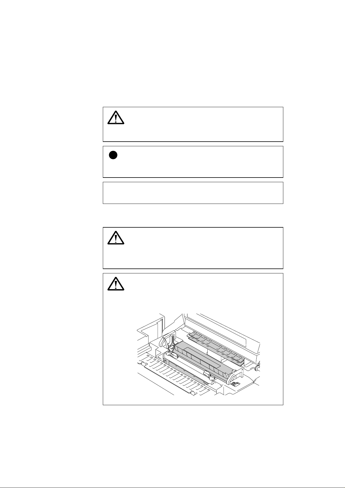
Warning
This printer is heavy and weighs approximately 56kg (124lbs).
When you move or lift this printer, be sure at least 2 people lift it
together.
Warning
The Fusing Unit becomes extremely
operation. Wait until it has cooled down sufficiently (about 20
minutes) before replacing consumables.
Fig. 0-1 Fusing unit
ii
(approx. 150 ºC) during
HOT
Page 7
Warning
HARMFUL OZONE GAS
Inhalation of an excessive amount of ozone can adversely affect your
respiratory system.
An Ozone Filter is included to reduce ozone exhaust. This filter must
be replaced periodically in accordance with the instructions found in
your user manual.
Warning
If metal objects, water or other liquids get inside the printer, turn the
printer off immediately and unplug the printer. Contact your dealer.
Warning
Do not put consumables such as the Toner Cartridges and the Waste
Toner Pack into a fire. Some consumables may be flammable under
certain conditions.
Warning
Do not look directly at the laser beam light. It might cause damage to
your eyesight. Do not remove or break open the printer’s safety
interlocks.
Warning
Do not run the printer with the Top Cover, Front Cover and Rear
Access Covers open and the interlocks removed.
Warning
Turn off the printer before replacing consumables.
Warning
Do not place any items on the printer.
iii
Page 8
Warning
In case of a fuser oil spill, you must clean it up immediately .
Warning
Do not put any pressure on the Feeder Cassette or the Front Cover
when it is opened. If you do so, you might get injured because there is
a possibility that the printer can fall on you.
iv
Page 9
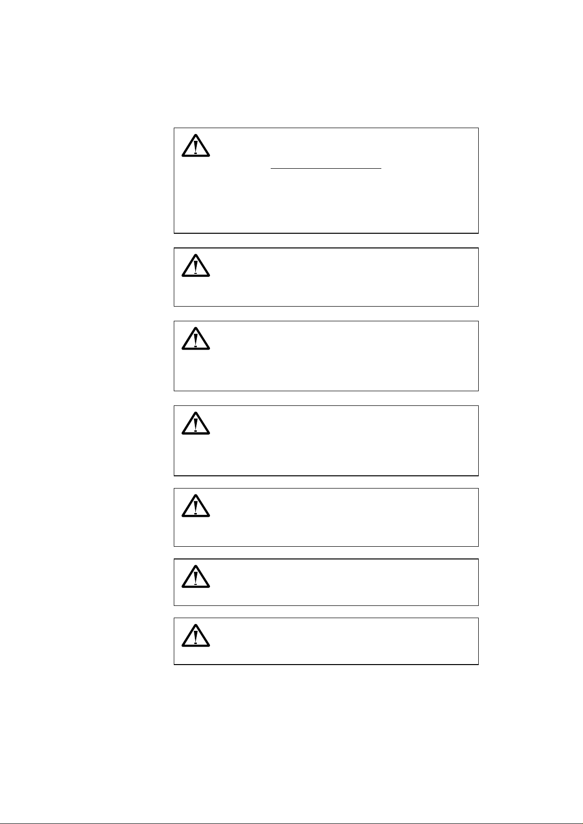
Printer Do's and Don'ts for Optimum Print Quality
Caution
!
Before you move or lift the printer, remove the Toner Cartridges, Waste
Toner Pack, Oil Bottle and Fusing Unit to avoid spills. Be sure to keep
the printer as level as possible. Damage caused by failure to remove the
supplies will void your warranty.
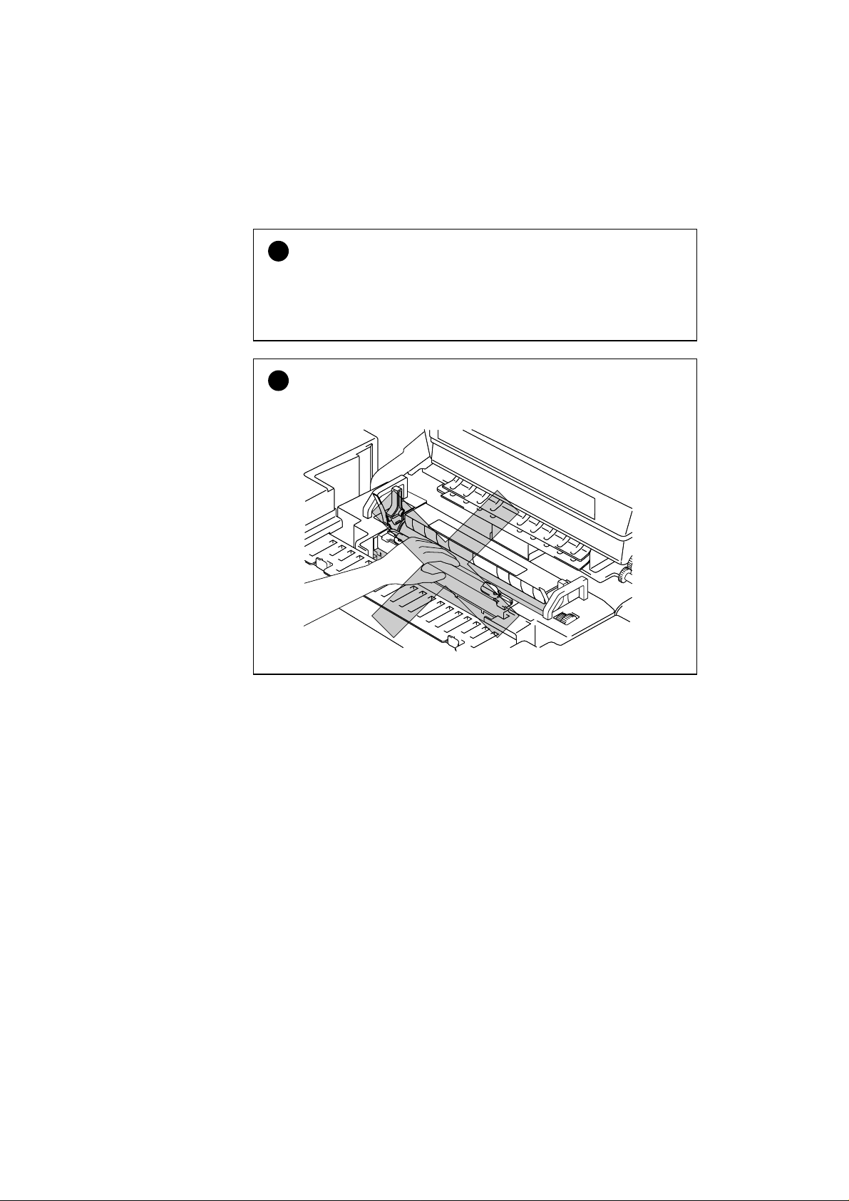
Caution
!
Do not touch the rollers of the Fusing Unit. This can degrade print
quality.
Fig. 0-2 Fusing Unit Rollers
v
Page 10

USER’S GUIDE
TABLE OF CONTENTS
CHAPTER 1 INTRODUCTION
ABOUT THIS MANUAL 1-1
ABOUT THIS PRINTER 1-2
Features 1-2
Options 1-6
Operating and Storage Environment 1-8
CHAPTER 2 SETTING UP THE PRINTER
BEFORE USING THE PRINTER 2-1
Checking the Components 2-1
General View 2-3
SETTING UP THE PRINTER 2-4
Remove the Protective Parts 2-4
Install the OPC Belt Cartridge 2-5
Install the Toner Cartridges 2-7
Install the Oil Bottle and the Fuser Cleaner 2-10
Loading Paper in the Media Cassette 2-13
Connecting the Printer to Your Computer 2-17
Turning the Printer On 2-19
Printing the Test Patterns or Lists 2-21
Install the Printer Driver 2-23
vi
Page 11

TABLE OF CONTENTS
CHAPTER 3 BEFORE WORKING WITH THE PRINTER
AUTOMATIC EMULATION SELECTION 3-1
AUTOMATIC INTERFACE SELECTION 3-3
ABOUT THE CONTROL PANEL 3-5
Selecting the Local Language Display 3-5
Using the Panel Buttons 3-6
Printer Settings 3-7
PAPER HANDLING 3-8
Print Media 3-8
Cassette Feed 3-16
Manual Feed 3-17
CHAPTER 4 CONTROL PANEL
DISPLAY AND LEDS 4-1
Display 4-1
About Routine Maintenance Messages 4-4
LEDs 4-5
BUTTONS IN NORMAL MODE 4-6
SEL Button 4-6
SET Button 4-7
s (UP) or t (DOWN) Button 4-7
MODE Button 4-8
INTERFACE MODE 4-19
FORMAT MODE 4-22
RESOLUTION MODE 4-30
PAGE PROTECTION 4-33
DEVICE OPERATION 4-34
ADVANCED MODE 4-43
PAGE COUNTER 4-50
EXIT MODE 4-50
FONT Button 4-51
FORM FEED Button (REPRINT Button) 4-61
CONTINUE Button 4-64
vii
Page 12

USER’S GUIDE
BUTTONS IN SHIFT MODE 4-65
SHIFT Button 4-65
EMULATION Button 4-66
ECONOMY Button 4-69
FEEDER Button 4-70
Duplex Mode 4-73
COPY Button 4-74
RESET Button 4-75
TEST Button 4-84
HEX DUMP MODE 4-86
CHAPTER 5 MAINTENANCE
REPLACING THE CONSUMABLES 5-1
Toner Cartridges 5-3
Oil Bottle 5-6
Fuser Cleaner 5-9
Waste Toner Pack 5-12
OPC Belt Cartridge 5-14
Ozone Filter 5-17
Fusing Unit 5-18
120K Kit 5-22
240K Kit 5-25
viii
CLEANING THE PRINTER 5-30
REPACKING AND RELOCATING THE PRINTER 5-32
OPTIONS 5-33
Lower Tray Unit 5-33
Duplex Unit 5-40
Font Card, Flash Memory/HDD Card 5-50
Installing a Font Card, Flash Memory Card and HDD Card 5-50
Selecting the Optional Fonts 5-52
Network Option 5-53
Modular I/O Card 5-53
RAM Expansion 5-56
HDD (Hard Disk Drive) 5-59
Page 13

TABLE OF CONTENTS
CHAPTER 6 TROUBLE SHOOTING
TROUBLESHOOTING 6-1
Operator Call Messages 6-1
Maintenance Messages (appear on the lower row) 6-3
Error Messages 6-4
Service Call Messages 6-6
Paper Jams 6-9
Q & A 6-13
Setting Up the Printer 6-13
Setting Up the Printer 6-14
Paper Handling 6-15
Printing 6-16
Print Quality 6-17
APPENDICES
PRINTER SPECIFICATIONS A-1
Printing A-1
Functions A-2
Electrical and Mechanical A-3
PAPER SPECIFICATIONS A-4
INTERFACE SPECIFICATIONS A-8
Bi-directional Parallel Interface A-8
RS-232C Serial Interface A-11
Network Interface A-14
SYMBOL/CHARACTER SETS A-15
OCR Symbol Sets A-16
HP PCL Mode A-17
EPSON Mode A-24
IBM Mode A-27
HP-GL Mode A-29
Symbol Sets Supported by the Printer’s Intellifont Compatible Typefaces A-34
Symbol Sets Supported by the Printer’s TrueType™ and Type 1 Font Compatible,
and Original Typefaces A-36
INDEX
ix
Page 14

USER’S GUIDE
IMPORTANT INFORMATION: REGULATIONS
Electronic Emission Notices
WITHOUT the Network Card NC-2010h, NC-2100h
Federal Communications Commission(FCC) Declaration of
Conformity (For U.S.A. Only)
Responsible Party : Brother International Corporation
100 Somerset Corporate Boulevard
Bridgewater, NJ 08807-0911, U.S.A.
TEL : (908) 704-1700
declares, that the products
Product Name : Brother Color Laser Printer HL-3400CN
Model Numbers : HL-3400C
Product Options : Lower Tray Unit LFU-3 and Duplex Unit DUP-3
HDD (HD-6G)
complies with Part 15 of the FCC Rules. Operation is subject to the following two
conditions: (1) This device may not cause harmful interference, and (2) this device
must accept any interference received, including interference that may cause
undesired operation.
This equipment has been tested and found to comply with the limits for a Class B
digital device, pursuant to Part 15 of the FCC Rules. These limits are designed to
provide reasonable protection against harmful interference in a residential
installation. This equipment generates, uses, and can radiate radio frequency energy
and, if not installed and used in accordance with the instructions, may cause
harmful interference to radio communications. However, there is no guarantee that
interference will not occur in a particular installation. If this equ ipment does cause
harmful interference to radio or television reception, which can be determined by
turning the equipment off and on, the user is encouraged to try to correct the
interference by one or more of the following measures:
- Reorient or relocate the receiving antenna.
- Increase the separation between the equipment and receiver.
- Connect the equipment into an outlet on a circuit different from that to which the
receiver is connected.
- Consult the dealer or an experienced radio/TV technician for help.
Important
A shielded interface cable should be used in order to ensure compliance with the
limits for a Class B digital device.
Changes or modifications not expressly approved by Brother Industries, Ltd. could
void the user’s authority to operate the equipment.
x
Page 15

REGULATIONS
Industry Canada Compliance Statement (For Canada Only)
This Class B digital apparatus complies with Canadian ICES-003.
Cet appareil numérique de la classe B est conforme à la norme NMB-003 du
Canada.
Declaration of Conformity (For Europe)
We, Brother Industries, Ltd.,
15-1, Naeshiro-cho, Mizuho-ku, Nagoya 467-8561, Japan
declare that this product is in conformity with the following normative documents.
Safety: EN 60950, EN 60825
EMC: EN 55022 Class B, EN 55024
following the provisions of the Low Voltage Directive 73/23/EEC and the
Electromagnetic Compatibility Directive 89/336/EEC (as amended by 91/263/EEC
and 92/31/EEC).
Issued by: Brother Industries, Ltd.
Printer Products Division
Radio Interference (220-240 V Model Only)
This printer complies with EN55022(CISPR Publication 22)/Class B.
Before this product is used, ensure that you use a double-shielded interface cable
with twisted-pair conductors and that it is marked “IEEE 1284 compliant”. The
cable must not exceed 1.8 meters in length.
xi
Page 16

USER’S GUIDE
WITH the Network Card NC-2010h, NC-2100h
EMC Notice
Warning
This is a Class A product. In a domestic environment this product may cause radio
interference in which case the user may be required to take adequate measures.
Federal Communications Commission(FCC) Compliance
Notice (For U.S.A. Only)
This equipment has been tested and found to comply with the limits for a Class A
digital device, pursuant to Part 15 of the FCC Rules. These limits are designed to
provide reasonable protection against harmful interference when the equipment is
operated in a commercial environment. This equipment generates, uses, and can
radiate radio frequency energy and, if not installed and used in accordance with the
instruction manual, may cause harmful interference to radio communications.
Operation of this equipment in a residential area is likely to cause harmful
interference in which case the user will be required to correct the interference at his
own expense.
Important
A shielded interface cable should be used in order to ensure compliance with the
limits for a Class A digital device.
Changes or modifications not expressly approved by Brother Industries, Ltd. could
void the user’s authority to operate the equipment.
Industry Canada Compliance Statement (For Canada Only)
This Class A digital apparatus complies with Canadian ICES-003.
Cet appareil numérique de la classe A est conforme à la norme NMB-003 du
Canada.
xii
Page 17

REGULATIONS
Declaration of Conformity (For Europe)
We, Brother Industries, Ltd.,
15-1, Naeshiro-cho, Mizuho-ku, Nagoya 467-8561, Japan
declare that this product is in conformity with the following normative documents.
Safety: EN 60950, EN 60825
EMC: EN 55022 Class A, EN 55024
following the provisions of the Low Voltage Directive 73/23/EEC and the
Electromagnetic Compatibility Directive 89/336/EEC (as amended by 91/263/EEC
and 92/31/EEC).
Issued by: Brother Industries, Ltd.
Printer Products Division
Radio Interference (220-240 V Model Only)
This printer complies with EN55022(CISPR Publication 22)/Class A.
Before this product is used, ensure that you use a double-shielded interface cable
with twisted-pair conductors and that it is marked “IEEE 1284 compliant”. The
cable must not exceed 1.8 meters in length.
International ENERGY STAR® Compliance
Statement
The purpose of the International E
development and popularization of ener gy-efficien t office equipments.
As an E
NERGY STAR
product meets the E
®
Partner, Brother Industries, Ltd. has determined that this
NERGY STAR
NERGY STAR
®
guidelines for energy efficiency.
®
Program is to promote the
xiii
Page 18
USER’S GUIDE
Laser Notices
Laser Safety (For 120 V Model Only)
This printer is certified as a Class I laser product under the U.S. Department of
Health and Human Services (DHHS) Radiation Performance Standard according
to the Radiation Control for Health and Safety Act of 1968. This means that the
printer does not produce hazardous laser radiation.
Since radiation emitted inside the prin ter is com pletely confined within
protective housings and external covers, the laser beam cannot escape from the
machine during any phase of user operation.
FDA Regulations (For 120 V Model Only)
U.S. Food and Drug Administration (FDA) has implemented regulations for laser
products manufactured on and after August 2, 1976. Compliance is mandatory for
products marketed in the United States.
Caution: Use of controls, adjustments or performance of procedures other than
those specified in this manual may result in hazardous radiation
exposure.
IEC 825 Specification (For 220 - 240 V Model Only)
This printer is a Class 1 laser product as defined in IEC 825 specifications. The
label shown below is attached in countries where required.
CLASS 1LASER PRODUCT
APPAREIL Å LASER DE CLASSE 1
LASER KLASSE 1 PRODUKT
xiv
Page 19
REGULATIONS
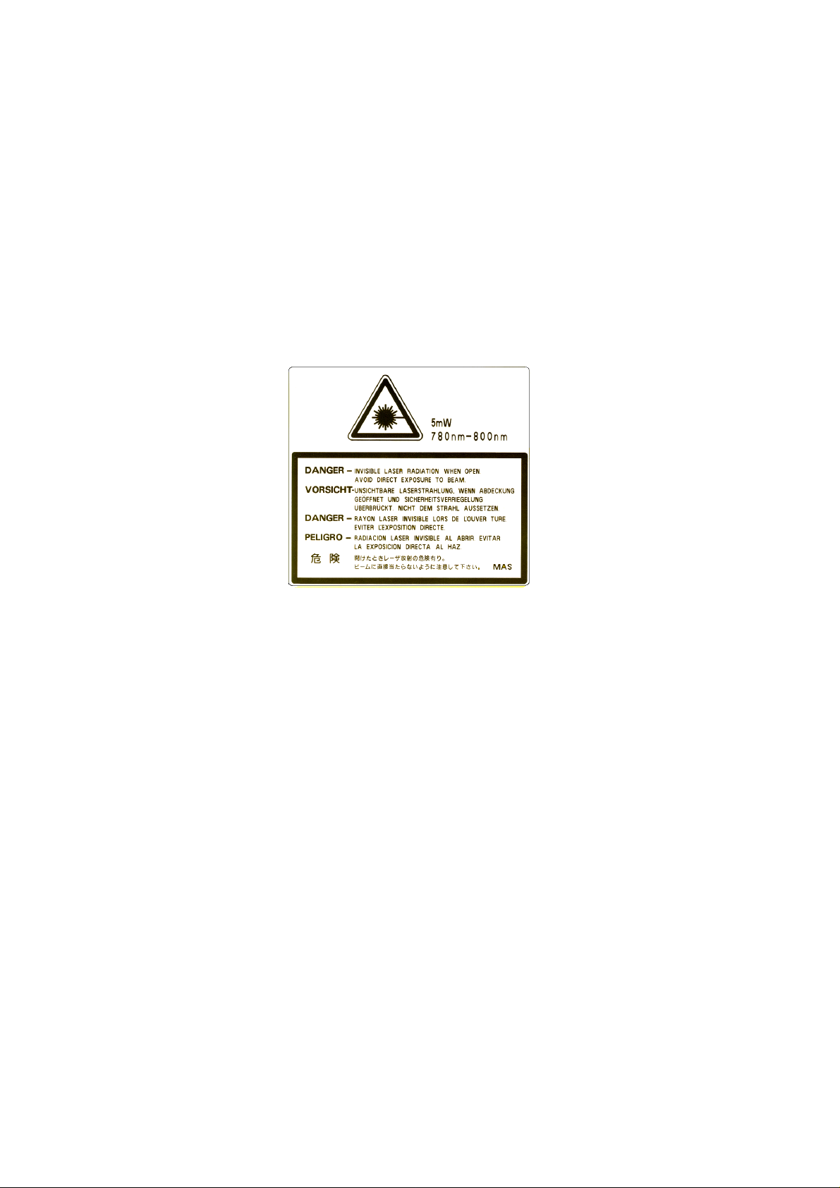
This printer has a Class 3B Laser Diode which emits invisible laser radiation in the
Scanner Unit. The Scanner Unit should not be opened under any circumstances.
Caution: Use of controls, adjustments or performance of procedures other than
those specified in this manual may result in hazardous radiation
exposure.
The following caution label is attached on the cover of the scanner
unit.
For Finland and Sweden
LUOKAN 1 LASERLAITE
KLASS 1 LASER APPARAT
Varoitus! Laitteen käyttäminen muulla kuin tässä käyttöohjeessa mainitulla tavalla
saattaa altistaa käyttäjän turvallisuusluokan 1 ylittävälle näkymättömälle
lasersäteilylle.
Varning – Om apparaten används på annat sätt än i denna Bruksanvisning
specificerats, kan användaren utsättas för osynlig laserstrålning, som överskrider
gränsen för laserklass 1.
xv
Page 20

USER’S GUIDE
Safety Information
IMPORTANT - For Your Safety
To ensure safe operation the three-pin plug supplied must be inserted only into a
standard three-pin power point that is effectively grounded through the normal
household wiring.
Any extension cords used with this printer must be three-conductor and be correctly
wired to provide connection to ground. Improper extension cords are a major cause
of fatalities.
The fact that the equipment operates satisfactorily does not imply that the power is
grounded and that the installation is completely safe. For your safety, if in any
doubt about the effective grounding of the power, consult a qualified electrician.
Disconnect device
This printer must be installed near a power outlet that is easily accessible. In case of
emergencies, you must disconnect the power cord from the power outlet to shut off
the power completely.
Geräuschemission / Acoustic Noise Emission (For
Germany Only)
Lpa < 70 dB (A) DIN 45635-19-01-KL2
Wiring Information (For U.K. only)
Important
If the power cord supplied with this printer is not suitable for your electrical outlet,
remove the plug from the mains cord and fit an appropriate three pin plug. If the
replacement plug is intended to take a fuse then fit a fuse with the same rating as
the original.
If a moulded plug is severed from the power cord then it should be destroyed
because a plug with cut wires is dangerous if plugged into a live socket outlet. Do
not leave it where a child might find it.
In the event of replacing the plug fuse, fit a fuse approved by ASTA to BS1362
with the same rating as the original fuse.
Always replace the fuse cover. Never use a plug with the cover omitted.
xvi
WARNING - THIS PRINTER MUST BE PROPERLY EARTHED.
Page 21

REGULATIONS
The wires in the mains cord are coloured in accordance with the following code:
Green and yellow: Ground
Blue: Neutral
Brown: Live
The colours of the wiring in the power lead of this printer may not correspond with
the markings which identify the terminals in your plug. If you need to fit a different
plug, proceed as follows.
Remove a length of the cord outer sheath, taking care not to damage the coloured
insulation of the wires inside.
Cut each of the three wires to the appropriate length. If the construction of the plug
permits, leave the green and yellow wire longer than the others so that, in the event
that the cord is pulled out of the plug, the green and yellow wire will be the last to
disconnect.
Remove a short section of the coloured insulation to expose the wires.
The wire which is coloured green and yellow must be connected to the terminal in
the plug which is marked with the letter “E” or by the eart h symbol
or coloured
green or green and yellow.
The wire which is coloured blue must be connected to the te rm inal which is marked
with the letter “N” or coloured black or blue.
The wire which is coloured brown must be connected to the terminal which is
marked with the letter “L” or coloured red or brown.
The outer sheath of the cord must be secured inside the plug. The coloured wires
should not hang out of the plug.
xvii
Page 22

CHAPTER 1 INTRODUCTION
ABOUT THIS MANUAL
This manual acts as your guide to the setup and operation of your printer
and covers the following topics:
CHAPTER 1 INTRODUCTION provides an overview of the printer.
Read this chapter first to get familiar with the printer.
CHAPTER 2 SETTING UP THE PRINTER gives you general set-up
information about this printer. Be sure to read this chapter before you use
the printer.
CHAPTER 3 BEFORE WORKING WITH THE PRINTER provides
detailed information for setting up the printer to work with your computer
and software. Be sure to read this chapter before you work with the
printer.
CHAPTER 1 INTRODUCTION
CHAPTER 4 CONTROL PANEL details the functions of the panel
buttons and LEDs.
CHAPTER 5 MAINTENANCE provides guidance on how to maintain
your printer.
CHAPTER 6 TROUBLESHOOTING helps you troubleshoot the
printer in case of problems.
APPENDICES contain printer specifications and paper specifications.
INDEX provides an alphabetical list of the contents of this manual.
✒ Notes
When you read this User’s Guide, note the following:
• This User’s Guide contains instructions or steps to teach you various
operations of the printer. Please remember that the instructions always
assume that you start with the factory settings, particularly in Chapter
2 and Chapter 3. If you change the settings, particularly the emulation
mode, the display messages change accordingly.
• The paper size has been factory set to letter or A4, depending upon
the final destination of the printer. Some display messages appear
differently according to this setting.
1-1
Page 23

USER’S GUIDE
ABOUT THIS PRINTER
Features
This printer has the following standard features.
2400 x 600 DPI Class Resolution
This printer prints at a default resolution of 600 dots per inch (dpi). By
utilizing the 300-dpi mode, the printer can also print lower resolution
data, if necessary. Moreover, you can achieve higher print quality
equivalent to 2400x600 DPI resolution, by utilizing these Brother
technologies: High Resolution Control (HRC) and Color Advanced
Photoscale Technology(CAPT).
High Speed and Color Laser Printing
You can print crisp images in brilliant 24-bit color.
This printer can print at a speed up to 24 pages per minute in
monochrome mode and 6 pages per minute in full color mode on A4/
Letter size paper. The controller utilizes a high speed 64-bit RISC
microprocessor and special hardware chips, so the process speed is very
fast.
Color Advanced Photoscale Technology (CAPT)
This printer can print graphics in 256 shades for each color in HP
printer PCL5C™ emulation and BR-Script level 2, producing nearly
photographic quality. This mode is effective when you print photographic
images.
High Resolution Control (HRC)
The High Resolution Control (HRC) technology provides clear and crisp
printouts and improves even the 600-dpi resolution. This mode is
effective when you print text.
Maintenance-Free and Economical Toner Cartridge
The toner cartridge can print up to 14,000 (Black) and 8,500 (Cyan,
Magenta and Yellow) single-sided A4 / Letter pages at 5% coverage. This
printer uses one piece, easy-to-replace toner cartridges.
®
color
1-2
Page 24

CHAPTER 1 INTRODUCTION
Universal Media Cassette
This printer loads paper automatically from the media cassette. Since the
media cassette is a universal type, a number of different paper sizes can
be used. Even envelopes can be loaded from the media cassette. For
detailed paper specifications, see ‘Paper Handling’ in Chapter 3.
Three Interfaces
This printer has a high speed bi-directional parallel interface, an RS-232C
serial interface and a modular input/output (MIO) compatible interface.
As an alternative to the MIO interface, you can use the Brother NC-3100h
Networking solution.
If your application software supports the bi-directional parallel interface,
you can monitor the printer status. It is fully compatible with the
industry-standard bi-directional parallel interface.
The RS-232C serial interface is an industry standard so that you can
connect it to any computer using a standard serial cable.
The MIO interface allows you to install a commercial MIO-compatible
card. If you install a card, you can use one more interface ports for
networking or printer sharing.
The NC-3100h card can enable you to connect directly to a Network.
Automatic Interface Selection
This printer can automatically select the bi-directional parallel, RS-232C
serial or MIO / NC-3100h interface depending on the interface port
through which it receives data. With this feature, the printer can be
connected to more than one computer.
Five Emulation Modes
This printer can emulate the Hewlett-Packard
®
(PCL6
in monochrome printing) printers, PostScript® Level 2 language
®
Color PCL® 5C language
emulation (Brother BR-Script Level 2) printers, the industry-standard HPGL™ plotter as well as EPSON
®
FX-850™ and IBM® Proprinter XL
®
printers (for monochrome printing only). You can print with all
application programs that support one of these printers.
1-3
Page 25

USER’S GUIDE
Automatic Emulation Selection
This printer can automatically select the printer emulation mode
depending on the print commands it receives from the computer software.
With this feature, many users can share the printer on a network.
Data Compression Technology
This printer can internally compress the received graphics and font data
in its memory so that it can print larger graphics and mo r e fonts without
the need for additional memory.
Various Fonts
This printer has 72 scalable and 12 bitmapped fonts. The fonts that can be
used vary according to the selected emulation mode.
In PCL mode, you can also print 11 kinds of bar codes. In BR-Script
mode, the printer has 66 scalable fonts.
Bar Code Printing
This printer can print the following 11 types of bar codes:
• Code 39 • UPC-E
• Interleaved 2 of 5 • Codabar
• EAN-8 • US-PostNet
• EAN-13 • ISBN
• UPC-A • Code 128
• EAN-128
CCITT G3/G4
Since this printer supports the CCITT G3/G4 format in addition to HPcompatible formats, it can quickly receive and print data compressed in
this format.
Lock Panel
If the panel button settings have been changed, the printer may not work
as you expect. If you are an administrator of this printer, you can lock
your settings to prevent changes from being made.
1-4
Page 26

CHAPTER 1 INTRODUCTION
Power Save Mode
This printer has a power saving mode. Since laser printers consume
power to keep the fixing assembly at a high temperature, this feature can
save electricity when the printer is on but not being used. The factory
setting of the Power Save mode is ON so that it complies with the new
EPA Energy Star specification.
Toner Save Mode
This printer has an economical Toner Save Mode. By using this feature
you can substantially reduce printer operating costs and extend the life
expectancy of the toner cartridges.
Reprint Function
You can reprint the last print job with a touch of a panel button, which
allows reprinting of multiple copies of the job without sending the data
again from the computer.
When there is not enough memory to print the last job, you can reprint
the last print page.
PCMCIA Card Slot
The printer has 2 Type II PCMCIA card slots that also allow the use of 1
Type III device. You can install PCMCIA-compatible flash memory and
HDD cards.
• Flash memory card: You can store fonts, macros, logos and other print data.
• HDD card: You can store fonts, macros, logos and other print
data as well as keeping data for printer usage analysis.
Saving User Settings
You can personalize the printer by customizing your own control panel
button settings. Two sets of user settings can be stored.
1-5
Page 27

USER’S GUIDE
Options
[Paper Handling]
The following options are available for this printer:
Lower Tray Unit (LT-34CL)
A lower tray unit expands the paper source capacity. You can load extra
paper or different sizes of paper. You can load 330 x 483mm (13"x19"),
Ledger, Letter, A3, A4, and legal paper into this cassette.
A4/ Letter Cassette (LC-34A)
You can load A4, B5 (JIS and ISO), Executive, Letter paper and Com 10,
C5 and DL envelopes from the A4/Letter Cassette.
Duplex Unit (DX-3400)
By installing the Duplex Unit DX-3400, you can perform duplex
printing.
You can print on 330 x 483 (13"x19"), A3, A4, B4, B5 (JIS and ISO),
Executive, Ledger, Legal and Letter size paper with the Duplex Unit
installed.
[Network]
The following commercial products can be installed into this printer:
✒ Note
Some models of this printer may include an MIO card or NC-3100h
network card as standard.
NC-3100h
Installing a NC-3100h enables you to use the printer in the following
environments:
(TCP/IP, IPX/SPX, AppleTalk, DLC/LLC, VINES, LAT, NetBEUI)
Also, many useful utilities such as BR-Admin and Brother Network
Printing software for the Network administrator are inclu ded. For details
of the utilities, see the documentation included on the CD-ROM.
MIO Card (NC-2010h/NC-2100h)
An MIO Network Card provides a means for attaching the printer to a
network.
1-6
Page 28

[PCMCIA CARDS]
Flash Memory Card and HDD Card
A commercial flash memory card or an HDD card can be installed. You
can store fonts, macros, logos, and other print data in a commercial
PCMCIA-compatible flash memory card or HDD card.
By using the card, you can do logging and custom web functions. You
also can use the Brother Analysis Tool software and the Brother Card
Monitor software. For more details on these utilities, please refer to the
documentation included on the CD-ROM.
HDD (Hard Disk Drive - HD-6G)
By installing an optional HDD, you can save multiple print jobs onto it.
You can also select your print job and re-print it through the network.
[RAM]
RAM Expansion
CHAPTER 1 INTRODUCTION
By installing commercial memory modules you can expand the memory
capacity up to 320 Mbytes.
✒ Note
Installation instructions for each options is provided in the manual
included with the option.
1-7
Page 29

USER’S GUIDE
Operating and Storage Environment
Please take note of the following before using the printer.
Power Supply
Use the printer within the specified power range.
AC power: ±10% of the rated power voltage
Frequency: 50/60 Hz (120V or 220-240 V)
The power cord, including extensions, should not exceed 5 meters (16.5 feet).
Do not share the same power circuit with other high-power appliances, particularly
an air conditioner, copier, shredder, etc. If you must use the printer with these
appliances, we recommend that you use a voltage transformer or a high-frequency
noise filter.
Use a voltage regulator if the power source is not stable.
Environment
Use the printer only within the following ranges of temperature and humidity.
Ambient temperature: 10°C to 32.5°C (50°F to 90.5°F)
Ambient humidity: 20% to 80% (without condensation)
Do not block the air exit on top of the printer. Do not place objects on top of the
printer, especially on the air exit.
Ensure that the printer Ozone Filter is installed at all times.
Ventilate the room where you use the printer.
Do not place the printer where it will be exposed to direct sunlight. Use blinds to
protect the printer from direct sunlight if set up near a window is unavoidable.
Do not install the printer near devices that contain magnets or generate magnetic
fields.
Do not subject the printer to strong physical shocks or vibrations. Do not expose the
printer to open flames or salty or corrosive gasses.
Place the printer on a flat, horizontal surface.
Keep the printer clean. Do not install the printer in a dusty place.
1-8
Do not install the printer near an air conditioner.
Do not install the printer in a room with a humidifier.
Page 30
CHAPTER 1 INTRODUCTION
)
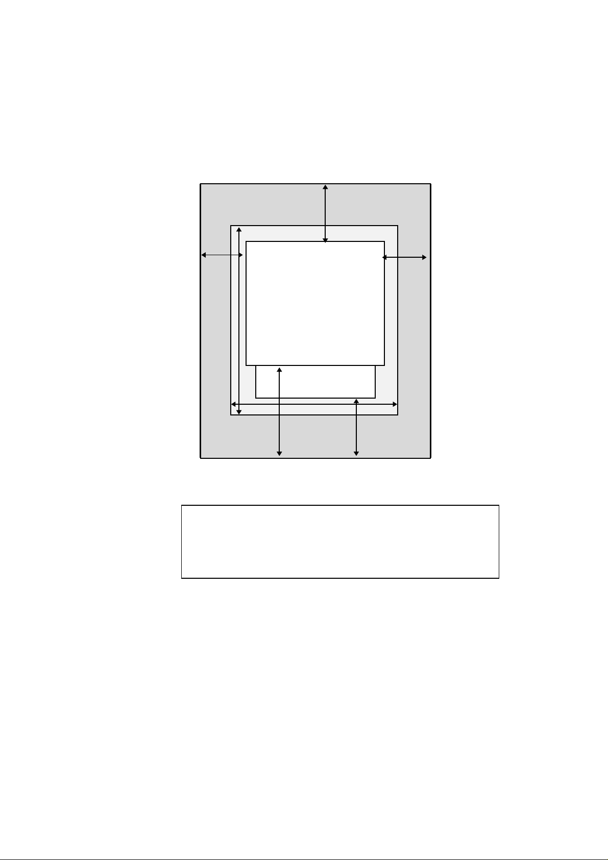
The following figure details the recommended area around the printer for proper
ventilation, operation and mainten an ce.
Rear
20cm(8"
Table
10cm (4")
50cm (20")
Printer
80cm(32")
Media Cassette
70cm(28")
70cm(28"
20cm(8")
Front
Fig. 1-1 Recommended area around the Printer
✒ Note
• Ensure that there is enough space behind the printer so that you can
easily access the rear cover or Duplex unit if a paper jam occurs.
• Make sure that the Paper Cassette does not extend past the edge of
the table where the printer is installed.
1-9
Page 31

CHAPTER 2 SETTING UP THE PRINTER
CHAPTER 2
SETTING UP THE PRINTER
This chapter can also be used as a quick setup guide, which provides information for
setting up the printer.
BEFORE USING THE PRINTER
Warning
This printer is heavy and weighs approximately 56kg (124 lbs). When
moving or lifting this printer, be sure to do so with at least 2 people to
avoid injury.
Checking the Components
After unpacking the printer, check to see that you have all of the
following parts:
Printer
OPC Belt Cartridge
Envelope Adapter
Standard Media
Oil Syringe
Printer Reference Guide
and Quick Setup Guide
Cassette
Oil Bottle
Fuser Cleaner
Toner Cartridges
(Black, Cyan, magenta
and Yellow)
Power Cord
CD-ROM
Fig. 2-1 Components in the Printer Carton
Caution
!
The Toner Cartridges, OPC Belt cartridge, Oil Bottle and Fuser Cleaner
are packed inside a separate carton as a starter kit. Do not open them now.
Only open them when you are ready to install them. The OPC Belt
Cartridge must not be exposed to light for any length of time or it will be
damaged.
2–1
Page 32

USER’S GUIDE
✒ Note
An interface cable is not a standard accessory. Please purchase the
appropriate cable for the interface you intend to use. Parallel cables
should be IEEE 1284 compliant and should not exceed 1.8metres (6 feet)
in length. The power cord may differ slightly from this diagram
depending on the country where you purchased the printer.
✒ Note
You may have additional parts not listed above, depending on which
country you live in and the HL-3400CN series model purchased.
✒ Note
We recommend keeping a spare of the following consumables at all
times. When the following consumables are exhausted, the printer will
cease printing.
* Toner Cartridges (TN-02BK, TN-02C, TN-02M, TN-02Y)
* Waste Toner Pack (WT-2CL)
* Oil Bottle (FO-2CL)
*Fuser Cleaner ( CR-2CL)
2–2
Page 33

General View
Control Panel
Power Button
CHAPTER 2 SETTING UP THE PRINTER
Top Cover
Front Cover
Rear Side Cover
Rear Access Cover
Media Cassette
Fig. 2-2 Front View
Controller Box
Power Cord
Connector
Fig. 2-3 Rear View
2–3
Page 34

USER’S GUIDE
SETTING UP THE PRINTER
Remove the Protective Parts
After checking that you have all of the correct parts, temporarily place the
printer where you can easily reach all sides. Remove the protective parts
that secure the printer against damage during transportation, as shown
below:
✒ Important Note
It is CRITICAL that you save all packing materials in the event you must
ship or store the printer. Failure to empty, clean and correctly repack the
printer according to the manufacturer’s instructions BEFORE shipment
will result in serious damage to the printer. This damage may not be
covered by your warranty.
1. Remove the protective parts as shown below.
2–4
Fig. 2-4 Removing the Protective Parts
Page 35

Install the OPC Belt Cartridge
Caution
!
Do not touch the green surface of the OPC Belt Cartridge. This can
•
degrade print quality.
Do not expose the OPC Belt to light (more than 800 lux) for more
•
than approximately 2 minutes. It might cause damage to the OPC Belt
Cartridge and void the warranty.
1. Open the Top Cover and the Front Cover.
CHAPTER 2 SETTING UP THE PRINTER
Fig. 2-5 Open the Top Cover
2. Release both green Belt Cartridge Lock Levers by pulling them
toward you.
Fig. 2-6 Release the Levers
2–5
Page 36

USER’S GUIDE
3. Remove the orange OPC Belt Tension Release Pins from both sides of
the OPC Belt Cartridge.
Fig. 2-7 Remove the Pins
4. Remove the Protective Sheet from th e OPC Belt Cartridge.
Fig. 2-8 Remove the Protective Sheet
5. Insert the OPC Belt Cartridge into the printer cartridge guide with the
flat side facing you.
Fig. 2-9 Insert the (OPC) Belt Cartridge
6. Lock the Belt Cartridge Lock Levers by pushing them backward until
they click into place.
7. Close the Top Cover and the Front Cover.
2–6
Page 37

Install the Toner Cartridges
This printer uses 4 separate color (Black, Cyan, Magenta and Yellow)
toner cartridges. One of each is supplied. A new cartridge contains
enough toner to print up to 14,000 (Black): 8,500 (Cyan, Magenta,
Yellow) A4 or letter-size single-sided pages at about 5% coverage.
(Actual toner yield will depend on the images being printed.)
✒ Note
The toner cartridges shipped with the printer are
contain only half the normal amount of toner. (7,000 pages (Black) and
4,250 A4 pages (Cyan, Magenta and Yellow)).
To install the toner cartridges, follow these steps:
1. Open the Front Cover of the printer.
CHAPTER 2 SETTING UP THE PRINTER
cartridges that
starter
Fig. 2-10 Open the Front Cover
2. Remove the tape labeled 'REMOVE' from the toner cartridge.
Fig. 2-11 Removing the Tape
2–7
Page 38

USER’S GUIDE
3. After rocking each of the cartridges 3 to 4 times from side to side,
remove the orange Protective Cover fr om the Toner Cartridges.
Fig. 2-12 Rocking Cartridges and Removing the Protective Cover
4. Install the 4 toner cartridges by positioning them in the correct guides.
Each color cartridge is individually keyed to prevent improper
installation. Match each cartridge color label to the corresponding
color label on the printer.
2–8
Fig. 2-13 Install the Toner Cartridges
5. Close the Front Cover.
Page 39

CHAPTER 2 SETTING UP THE PRINTER
Caution
!
Insert the toner cartridges gently into the printer. Do not try to lock
•
them into the printer by pushing them all the way into the cartridge
guide. The cartridges will be correctly positioned when the front cover
is closed.
Do not stand the toner cartridge on its end or turn it upside down.
•
Install the toner cartridges immediately after you remove the
•
protective cover. Do not touch the shaded part shown below.
Fig. 2-14 Toner Cartridge
2–9
Page 40

USER’S GUIDE
Install the Oil Bottle and the Fuser Cleaner
1. Open the Top Cover.
2. Unlock the Cleaning Roller Lock Levers and Oil Bottle Lo ck Levers.
Fig. 2-15 Release the Levers
3. Move the Pressure Release Levers in the Fusing Unit to the SET position.
Fig. 2-16 Set the Levers to the SET position
2–10
Page 41

CHAPTER 2 SETTING UP THE PRINTER
4. Install the Oil Bottle into the Fusing Unit with the label side facing you. The Oil Bottle
is keyed to prevent incorrect installation.
Caution
!
Do not spill oil inside the printer. If oil does spill, it might cause damage
to the printer. If you do spill any oil, consult your dealer or an authorized
Brother service representative.
5. Lock the Oil Bottle in place by turning the Oil Bottle Lock Levers.
Fig. 2-17 Install the Oil Bottle
Fig. 2-18 Lock the Oil Bottle Lock Levers
2–11
Page 42

USER’S GUIDE
6. Place the Fuser Cleaner into the Fusing Unit with the roller side facing you.
Fig. 2-19 Install the Fuser Cleaner
7. Lock the Fuser Cleaner in place by turning the Fuser Cleaner Lock Levers.
Fig. 2-20 Lock the Fuser Cleaner Lock Levers
8. Close the Top Cover.
2–12
Page 43

Loading Paper in the Media Cassette
✒ Note
This printer has a 250 sheet Media Cassette as standard. An additional
Lower Tray Unit is available as an option.
Since the Media Cassette supports universal paper types, you can place
13"x19", Ledger, Letter, A3, A4, B4, B5, Legal or Executive size cut
sheet paper or COM10 or DL size envelopes in it.
The paper sources have the following limitatio ns. For more information
about paper, see “Paper Handling” in Chapter 3.
Paper source Available sizes Capacity
Standard
Media
Cassette
Optional
Lower
Cassette
Optional
A4/Letter
Cassette
cut sheet : Ledger, Letter, A4, A3,
B5(ISO), B5(JIS), B4,
Executive, Legal,
330x483mm(13"x19")
envelope: COM 10, DL
OHP film: A4, letter
other sizes: width 210-330mm
(8.2”-12.9”)
length 176-483mm
(6.9”-18.8”)
cut sheet : Ledger, Legal, Letter, A4, A3, B4
OHP film: A4, letter
other sizes: width 210-297mm
(8.2”-11.6”)
length 176-420mm
(6.9”-16.4”)
cut sheet: Letter, A4, B5(JIS), B5( ISO)
envelopes: COM 10, DL
OHP film: A4, letter
other sizes: width 105-216mm
(4.1”-8.5”)
length 220-335.6mm
(8.7”-14”)
CHAPTER 2 SETTING UP THE PRINTER
250
30
50
Up to approx. 250
sheets of 75g/m
(20 lbs.) paper
500
50
Up to approx. 500
sheets of 75g/m
( 20 lbs.) paper
250
30
50
Up to approx. 250
sheets of 75g/m
( 20 lbs.) paper
2
2
2
2–13
Page 44

USER’S GUIDE
To install the Media Cassette follow these steps to set the paper guides:
✒
Note
Be sure to select the same paper size in your application software, or
•
printing errors will occur.
If your application software does not support paper size selection in
its print menu, you can change the paper size with the
Mode
button in
the FORMAT MODE. For paper size change information, see
“MODE Button” in Chapter 4.
The default paper size has been factory set to letter or A4, depending
•
upon the final destination of the printer.
•120V model: Letter size paper set.
•220/240V model: A4 size paper set.
Small Size Setting: See “Control Panel” in Chapter 4
•
Load paper into the Media Cassette as follows:
1. Remove the cover from the front of the cassette.
2–14
Fig. 2-21 Remove the Cover
Page 45

CHAPTER 2 SETTING UP THE PRINTER
2. Adjust the Paper Guides to accommodate the paper size you
wish to use. Hold the shaded parts shown below and gently
slide the guides into place.
Fig. 2-22 Adjust the Paper Guides
3. Load paper into the Media Cassette and refit the paper cassette
cover.
2–15
Page 46

USER’S GUIDE
✒ Note
Adjust the tray to the correct paper size indication arrow. If you do
•
not adjust it correctly, the printer may detect the wrong size of paper.
2
Do not load more than 250 sheets of paper (90 g/m
•
or 24 lbs.) in the
cassette, or paper jams may occur. Paper (90 g/m2 or 24 lbs.) should
NOT be loaded above the top line on the guide.
Fig. 2-23 Paper Lines
4. Install the Media Cassette into the printer.
2–16
Page 47

Connecting the Printer to Your Computer
This printer has a bi-directional parallel interface and an RS-232C serial
interface. They allow the printer to communicate with IBM/PC
compatible computers. Before connecting the printer and computer,
purchase a cable specifically made for the interface you plan to use.
Since the automatic interface selection mode has been factory set, simply
connect the interface cable to the printer. In some cases, you need to turn
off the high-speed and bi-directional parallel communications with the
button. For further information, see “MODE Button” in Chapter 4 .
Mode
When you use the serial interface, you need to have the same
communications settings on both the printer and computer. Since the
automatic interface selection mode has been factory set with certain
factory settings (baud rate = 9600, code type = 8 bits, parity = none, stop
bit = 1, Xon/Xoff = ON, DTR (ER) = ON, and Robust Xon = ON), you
may simply connect the interface cable if these are the same as the
settings on your computer. When necessary, set the communications
parameters with the
see “MODE Button” in Chapter 4. For the settings on the computer, refer
to the manual of the computer or software you use.
Connect the printer to your computer as follows:
1. Make sure that both the computer and printer are turned off.
button on the printer. For further information,
Mode
CHAPTER 2 SETTING UP THE PRINTER
®
or
Caution
!
Always turn off the printer and computer when connecting and
disconnecting the cable.
✒
Note
To use the parallel connection, only a shielded interface cable that is
IEEE 1284 compliant and less than 1.8m (6 feet ) long should be used.
2. Connect one end of the interface cable to the interface
connector located on the back of the printer.
2–17
Page 48

USER’S GUIDE
3. Secure the connection to the printer with the wire clips or
screws.
Serial Interface Port
Secure connection with screws.
Computer Printer
Parallel Interface Port
Secure connection with wire clips.
Fig. 2-24 Connecting the Printer and Computer
4. Attach the other end of the interface cable to the interface
connector on your computer. Be sure to tighten the connection
on the computer as well.
2–18
✒ Note
When you connect to a network, you can use the Brother NC-3100h ,
NC-2010h, or NC-2100h network cards. For more details, refer to the
Network User’s Guide.
Page 49

Turning the Printer On
Installing the Power Cord and Turning the Printer On
1. Make sure that the
button is on the front left side of the printer.
2. Attach the power cord to the printer and plug it into an
appropriate AC outlet.
Power
CHAPTER 2 SETTING UP THE PRINTER
button is turned OFF. The power
Fig. 2-25 Plugging in the Power Cord
3. Turn the printer ON by pressing the
Caution
!
Check the AC voltage. This printer should be operated at the specified
•
voltage and frequency.
• USA and Canada: AC 120 V, 50/60 Hz
• Europe, Australia and others: AC 220 to 240 V, 50/60 Hz
Since this printer must be electrically grounded, the power cord
•
should be connected to a grounded AC outlet.
The total length of the power cord, including extension cords, should
•
not exceed 5 metres (16.4 feet). Use of a longer power cord may result
in reduced voltage or malfunctions.
Do not unplug the power cord to turn off the printer.
•
The printer should be installed near a power outlet that is easily
•
accessible.
Button.
Power
2–19
Page 50

USER’S GUIDE
Caution
!
Always wait at least 5 seconds after turning off the power before turning
it on again.
Do not turn the power off while the printer is printing as this may cause a
paper jam and adversely affect the printer.
The printer performs self-diagnosis at start-up to check its hardware and
software. If the printer should find any problems, the display will change
to show the corresponding error message. See “TROUBLESHOOTING”
in Chapter 6.
The display shows several messages quickly at start-up. If the printer
detects no errors, the printer initializes. This will take several minutes
during which time the LCD will display the following message:
LJ WAIT 001P T1
AUTO
Once the printer has finished initializing, it au to m a tically goes on-line
and the message changes to show the current printer status and
settings as shown below:
LJ READY 001P T1
AUTO
AUTO: The auto emulation selection mode is set.
LJ: The auto emulation selection is set and
the HP PCL5C emulation is currently selected.
READY: The printer is ready to print.
001: The number of copies to print is set to 1.
P: Portrait print is selected.
T1: Paper is fed from Tray1.
I : Toner cartridges are full.
NOTE: When the toner cartridges become nearly empty, the
indication blinks. The I indication disappears when a
I
color toner is empty.
K C M Y
K C M Y
2–20
Page 51

Printing the Test Patterns or Lists
You can check print quality and print a list of available fonts before you
actually start working with the printer. To do so, follow these steps:
1. Make sure that you have already installed the toner cartridges,
the OPC Belt Cartridge, the Oil Bottle and the Fuser Cleaner
and have loaded paper into the cassette. Make sure that you
have removed the protective parts on the Waste Toner Pack.
2 Turn on the printer. Wait until the display shows the following
message:
LJ READY 001P T1
AUTO
CHAPTER 2 SETTING UP THE PRINTER
3. Press the
The
On Line
4. Hold down the
K C M Y
button to take the printer off-line.
Sel
LED goes off.
button and press the
Shift
button. Release
Test
both buttons.
5. Press the ▲ or ▼ button to scroll through the display until the
desired message appears.
Choose from one of the following selections:
To Print LCD Message
the Demonstration Page
the Test Pattern
the list of printer settings
the list of internal or resident fonts
the list of optional card fonts
the list of permanent download fonts
✒ Notes
To exit from the test mode, select “
DEMO PAGE
TEST PRINT
PRINT CONFIG
PRINT FONTS I
PRINT FONTS C
PRINT FONTS P
”.
exit
The messages “PRINT FONTS C” or “PRINT FONTS P” appear only
when an optional font card is installed in the font slot or when permanent
download fonts are stored in printer memory.
If the optional font card is installed, you can print a list of optional
•
fonts. Since the list shows the ID numbers specific to each optional
font, it helps you select them with the
button. For more
Font
information, see “FONT Button” in Chapter 4.
If user-defined characters are already downloaded into the printer
•
memory as permanent download fonts, you can print a list of them.
For more information, see “FONT Button” in Chapter 4.
2–21
Page 52

USER’S GUIDE
6. Press the
Set
button.
The printer starts printing the selected test pattern or list. When the
printer finishes printing, it automatically returns to the off-line mode.
Press the SEL button to place the printer back on-line.
TEST PRINT
!"#$%&'()*+,-./1234567890:;@ABCDEFGHIJKLMNOPQRSTUVWXYZ[\]^_`abcdefghijklmnopqrstuvwxyz[|
"#$%&'()*+,-./1234567890:;@ABCDEFGHIJKLMNOPQRSTUVWXYZ[\]^_`abcdefghijklmnopqrstuvwxyz{\}
#$%&'()*+,-./1234567890:;@ABCDEFGHIJKLMNOPQRSTUVWXYZ[\]^_`abcdefghijklmnopqrstuvwxyz{\}~
$%&'()*+,-./1234567890:;@ABCDEFGHIJKLMNOPQRSTUVWXYZ[\]^_`abcdefghijklmnopqrstuvwxyz{\}~!
%&'()*+,-./1234567890:;@ABCDEFGHIJKLMNOPQRSTUVWXYZ[\]^_`abcdefghijklmnopqrstuvwxyz{\}~!"
&'()*+,-./1234567890:;@ABCDEFGHIJKLMNOPQRSTUVWXYZ[\]^_`abcdefghijklmnopqrstuvwxyz{\}~!"#
'()*+,-./1234567890:;@ABCDEFGHIJKLMNOPQRSTUVWXYZ[\]^_`abcdefghijklmnopqrstuvwxyz{\}~!"#$
()*+,-./1234567890:;@ABCDEFGHIJKLMNOPQRSTUVWXYZ[\]^_`abcdefghijklmnopqrstuvwxyz{\}~!"#$%
)*+,-./1234567890:;@ABCDEFGHIJKLMNOPQRSTUVWXYZ[\]^_`abcdefghijklmnopqrstuvwxyz{\}~!"#$%&
*+,-./1234567890:;@ABCDEFGHIJKLMNOPQRSTUVWXYZ[\]^_`abcdefghijklmnopqrstuvwxyz{\}~!"#$%&'
+,-./1234567890:;@ABCDEFGHIJKLMNOPQRSTUVWXYZ[\]^_`abcdefghijklmnopqrstuvwxyz{\}~!"#$%&'(
,-./1234567890:;@ABCDEFGHIJKLMNOPQRSTUVWXYZ[\]^_`abcdefghijklmnopqrstuvwxyz{\}~!"#$%&'()
-./1234567890:;@ABCDEFGHIJKLMNOPQRSTUVWXYZ[\]^_`abcdefghijklmnopqrstuvwxyz{\}~!"#$%&'()*
./1234567890:;@ABCDEFGHIJKLMNOPQRSTUVWXYZ[\]^_`abcdefghijklmnopqrstuvwxyz{\}~!"#$%&'()*+
/1234567890:;@ABCDEFGHIJKLMNOPQRSTUVWXYZ[\]^_`abcdefghijklmnopqrstuvwxyz{\}~!"#$%&'()*+,
1234567890:;@ABCDEFGHIJKLMNOPQRSTUVWXYZ[\]^_`abcdefghijklmnopqrstuvwxyz{\}~!"#$%&'()*+,234567890:;@ABCDEFGHIJKLMNOPQRSTUVWXYZ[\]^_`abcdefghijklmnopqrstuvwxyz{\}~!"#$%&'()*+,-.
34567890:;@ABCDEFGHIJKLMNOPQRSTUVWXYZ[\]^_`abcdefghijklmnopqrstuvwxyz{\}~!"#$%&'()*+,-./
4567890:;@ABCDEFGHIJKLMNOPQRSTUVWXYZ[\]^_`abcdefghijklmnopqrstuvwxyz{\}~!"#$%&'()*+,-./1
567890:;@ABCDEFGHIJKLMNOPQRSTUVWXYZ[\]^_`abcdefghijklmnopqrstuvwxyz{\}~!"#$%&'()*+,-./12
67890:;@ABCDEFGHIJKLMNOPQRSTUVWXYZ[\]^_`abcdefghijklmnopqrstuvwxyz{\}~!"#$%&'()*+,-./123
7890:;@ABCDEFGHIJKLMNOPQRSTUVWXYZ[\]^_`abcdefghijklmnopqrstuvwxyz{\}~!"#$%&'()*+,-./1234
890:;@ABCDEFGHIJKLMNOPQRSTUVWXYZ[\]^_`abcdefghijklmnopqrstuvwxyz{\}~!"#$%&'()*+,-./12345
90:;@ABCDEFGHIJKLMNOPQRSTUVWXYZ[\]^_`abcdefghijklmnopqrstuvwxyz{\}~!"#$%&'()*+,-./123456
ABC
TEST PRINT PRINT CONFIG
(LJ):HP LaserJet 4 (BS):BR-Script 2 (GL):HP-GL
(FX):EPSON FX-850 (PR):IBMProprinterXL
PAGE COUNTER = 682
RAM SIZE = 10Mbyte
USER SETTINGS SETTING1 SETTING2
< EMULATION >
EMULATION AUTO LaserJet4 AUTO LaserJet4 AUTO LaserJet4
AUTO TIME OUT (S) 5 5 5
EPSON/IBM EPSON EPSON EPSON
KEEP PCL OFF OFF OFF
< MODE >
- INTERFACE MODE I/F PARALLEL <- < AUTO TIME OUT (S) 5 <- < PRL SETTING
HIGH SPEED ON <- < BI-DIR ON <- < RS-232C SETTING
BaundRate (BAUD) 9600 <- < CodeType (bits) 8 <- < Parity NONE <- < Stop Bit (bits) 1 <- < Xon/Xoff ON <- < DTR(ER) ON <- < Robust Xon OFF <- <-
- FORMAT MODE ORIENTATION PORTRAIT <- < AUTO MODE
(LJ)
AUTO LF OFF OFF OFF
AUTO CR OFF OFF OFF
AUTO WRAP OFF OFF OFF
AUTO SKIP ON ON ON
(FX)
AUTO LF OFF OFF OFF
AUTO MASK OFF OFF OFF
(PR)
AUTO LF OFF OFF OFF
AUTO CR OFF OFF OFF
AUTO MASK OFF OFF OFF
PAGE FORMAT MODE
X OFFSET (dots) 0 <- < Y OFFSET (dots) 0 <- < PAPER A4 A4 A4
(LJ)
LEFT M (C) 0 0 0
RIGHT M (C) 78 78 78
TOP M (") 0.5 0.5 0.5
BOTTOM M (") 0.5 0.5 0.5
LINES (L) 64 64 64
(FX)
LEFT M (C) 0 0 0
RIGHT M (C) 80 80 80
TOP M (") .33 .33 .33
BOTTOM M (") .33 .33 .33
LINES (L) 66 66 66
(PR)
LEFT M (C) 0 0 0
RIGHT M (C) 80 80 80
TOP M (") .33 .33 .33
BOTTOM M (") .33 .33 .33
LINES (L) 66 66 66
- RESOLUTION MODE RESOLUTION (DPI) 600 <- < HRC MEDIUM <- <-
PRINT CONFIGURAITION(1/2)
PORTRAIT LIST
NUMBER SYMBOL SET
(ID) PITCH SIZE STYLE WEIGHT TYPEFACE F O N T S A M P L E(600dpi)
I000 8U:ROMAN 8...
P: Scalable Upright(0) Medium(0) PcTENNES Reg (4101)
ESC(IDESC(s1p#v0s0b4101T (#:point size 0.25 - 999.75)
I001 8U:ROMAN 8...
P: Scalable Upright(0) Bold(3) PcTENNES Bd (4101)
ESC(IDESC(s1p#v0s3b4101T (#:point size 0.25 - 999.75)
I002 8U:ROMAN 8...
P: Scalable Italic(1) Midium(0) PcTENNES It (4101)
ESC(IDESC(s1p#v1s0b4101T (#:point size 0.25 - 999.75)
I003 8U:ROMAN 8...
P: Scalable Italic(1) Bold(3) PcTENNES BdIt (4101)
ESC(IDESC(s1p#v1s3b4101T (#:point size 0.25 - 999.75)
I004 8U:ROMAN 8...
P: Scalable Upright(0) Medium(0) OKLAHOMA Reg (4113)
ESC(IDESC(s1p#v0s0b4113T (#:point size 0.25 - 999.75)
I005 8U:ROMAN 8...
P: Scalable Upright(0) Bold(3) OKLAHOMA Bd (4113)
ESC(IDESC(s1p#v0s3b4113T (#:point size 0.25 - 999.75)
I006 8U:ROMAN 8...
P: Scalable Italic(1) Medium(0) OKLAHOMA It (4113)
ESC(IDESC(s1p#v1s0b4113T (#:point size 0.25 - 999.75)
I007 8U:ROMAN 8...
P: Scalable Italic(1) Bold(3) OKLAHOMA BdIt (4113)
ESC(IDESC(s1p#v1s3b4113T (#:point size 0.25 - 999.75)
I008 8U:ROMAN 8...
P: Scalable Italic(1) Medium(0) CONNECTICUT (4116)
ESC(IDESC(s1p#v1s0b4116T (#:point size 0.25 - 999.75)
I009 8U:ROMAN 8...
P: Scalable Upright(4) Bold(3) CLEVELAND Cd (4140)
ESC(IDESC(s1p#v4s3b4140T (#:point size 0.25 - 999.75)
I010 8U:ROMAN 8...
P: Scalable Upright(0) Light(-3) PcBRUSSEL Lt (4143)
ESC(IDESC(s1p#v0s-3b4143T (#:point size 0.25 - 999.75)
I011 8U:ROMAN 8...
P: Scalable Upright(0) Bold(2) PcBRUSSEL Bd (4143)
ESC(IDESC(s1p#v0s2b4143T (#:point size 0.25 - 999.75)
I012 8U:ROMAN 8...
P: Scalable Italic(1) Light(-3) PcBRUSSEL LtIt(4143)
ESC(IDESC(s1p#v1s-3b4143T (#:point size 0.25 - 999.75)
I013 8U:ROMAN 8...
P: Scalable Italic(1) Bold(2) PcBRUSSEL BdIt(4143)
ESC(IDESC(s1p#v1s2b4143T (#:point size 0.25 - 999.75)
I014 8U:ROMAN 8...
P: Scalable Upright(0) Medium(0) UTAH Reg (4148)
ESC(IDESC(s1p#v0s0b4148T (#:point size 0.25 - 999.75)
I015 8U:ROMAN 8...
P: Scalable Upright(0) Bold(3) UTAH Bd (4148)
ESC(IDESC(s1p#v0s3b4148T (#:point size 0.25 - 999.75)
I016 8U:ROMAN 8...
P: Scalable Italic(1) Medium(0) UTAH It (4148)
ESC(IDESC(s1p#v1s0b4148T (#:point size 0.25 - 999.75)
I017 8U:ROMAN 8...
P: Scalable Italic(1) Bold(3) UTAH BdIt (4148)
ESC(IDESC(s1p#v1s3b4148T (#:point size 0.25 - 999.75)
ID:Symbol Set ID
INTERNAL FONT
ABCDefgh123?!"#$%&'()<>/012
ABCDefgh123?!"#$%&'()<>/01
ABCDefgh123?!"#$%&'()<>/012
ABCDefgh123?!"#$%&'()<>/012
ABCDefgh123?!"#$%&'()<>/0
ABCDefgh123?!"#$%&'()<>/0
ABCDefgh123?!"#$%&'()<>/0
ABCDefgh123?!"#$%&'()<>/0
ABCDefgh123?!"#$%&'()<>/0123456
ABCDefgh123?!"#$%&'()<>/
ABCDefgh123?!"#$%&'()<>/
ABCDefgh123?!"#$%&'()<>
ABCDefgh123?!"#$%&'()<>/
ABCDefgh123?!"#$%&'()<>
ABCDefgh123?!"#$%&'()<>/01
ABCDefgh123?!"#$%&'()<>/0
ABCDefgh123?!"#$%&'()<>/01
ABCDefgh123?!"#$%&'()<>/0
PRINT FONTS I
Fig. 2-26 Test Pattern, Setting List and Font List
*The test pattern, setting list and font list are subject to change without notice.
2–22
Page 53

Install the Printer Driver
Computer Requirements
The following are the minimum computer requirements to setup and
operate the printer:
CPU: 80486 or higher
RAM: 8 MB or more for Windows
Hard Disk Drive: 10Mbyte free space available for the driver and Fonts
OS: Windows
CHAPTER 2 SETTING UP THE PRINTER
(Pentium recommended)
4.0
NT
95/ 98, 3.1x and Windows
(16 MB or more recommended)
(more space is necessary for printing)
95/ 98, 3.1x and Windows NT 4.0
For Windows
3.1x, 95/98 & Windows NT
4.0 Users
You can configure your Windows Operating System for this printer by following
the Initial Setup instructions on the supplied CD-ROM.
1. Turn your PC power on and insert the CD-ROM into the CD-ROM drive.
2. The opening screen will appear automatically in Windows
4.0.
NT
95/98 or Windows
3. If the screen does not appear, click 'Start' and choose 'Run', enter the CD drive
letter and type 'START.EXE'.
If you are using Windows
3.1x, click 'Run' from the 'File Menu' in 'Program
Manager', enter the CD drive letter and type 'START.EXE'.
4. Select 'HL-3400CN series', and then select the language you require. Follow
the instructions that appear on screen..
5. Click the 'Install Driver & Software', select the printer driver type you want to
install.
6. After the printer driver has been installed, the HL-3400CN series window will
appear. Follow the onscreen messages to complete the installation.
2–23
Page 54

USER’S GUIDE
For Macintosh Users
✒ Note
The installer for the Macintosh driver works on OS System version
•
7.5.3 or higher.
The PPD file can be used with Laser Writer Driver version 8.4.3 or
•
higher.
1. Insert the CD-ROM into your CD-ROM drive.
2. Double click the 'BR-Script PPD Installer' icon.
3. Follow the instructions that appear on the screen.
✒ Notes
The installer automatically updates your SYSTEM.INI Windows
•
by adding DEVICE=bi-di.386 under the [386Enh] section. If any bidirectional parallel communications device driver was installed
previously, it will be deactivated by the new driver. If you wish to use
the old driver, you should re-install it. Re-installing the previous
driver will make the new HL-3400CN driver inactive.
The installer makes the installed printer driver the Windows
•
The installer automatically sets the printer port to the parallel
•
default.
interface, LPT1.
During this installation, changes have been made to the SYSTEM.INI
•
file. It is necessary to restart Windows so that the changes become
effective and the installed bi-directional parallel communications
device driver can take effect.
✒ Notes
For installation of other printer drivers and information on the latest
printer drivers see:
http://www.brother.com
file
2–24
Page 55

CHAPTER 3 BEFORE WORKING WITH THE PRINTER
CHAPTER 3
BEFORE WORKING WITH THE PRINTER
AUTOMATIC EMULATION SELECTION
This printer has an automatic emulation selection function. When the
printer receives data from the computer, it automatically selects the
emulation mode. This function has been factory set to ON.
The printer can select the emulation among the following combinations:
EPSON/IBM Priority EPSON (default) IBM
Auto Selection Mode HP PCL 5C HP PCL 5C
BR-Script 2 BR-Script 2
HP-GL HP-GL
EPSON FX-850 IBM Proprinter XL
To get the best possible color output, we recommend you use the Brother
BR-Script 2 emulation.
The printer is set to the HP color printer emulation (PCL5C) mode
automatically. Since PCL5C mode takes the highest priority in the
automatic emulation selection, you can start using the printer as it is with
the factory settings in most cases.
When the automatic emulation selection is active, you can check the
current emulation on the display. When the printer is in ready, print or
wait modes, the display reads as follows:
Emulation Status Display in Ready State
HP PCL5C LJ READY 001P T1
BR-Script 2 BS IDLE 001P T1
HP-GL GL READY 001P T1
EPSON FX-850 FX READY 001P T1
IBM Proprinter XL PR READY 001P T1
✒ Notes
Emulation modes other than PCL5C and BR-Script 2 are monochrome
emulation modes.
To select the emulation mode manually, use the
further information, see “EMULATION Button” in Chapter 4.
Emulation
button. For
3–1
Page 56

USER’S GUIDE
✒ Notes
When you use the automatic emulation selection, note the following:
• Once the emulation is automatically changed, it is not changed again
for a short period of time. This time period is called “Time Out” and it
can be set with the
Emulation
button. The factory setting is 5
seconds.
• The EPSON or IBM emulation mode priority must be selected, since
the printer cannot distinguish between them. The factory default
setting is EPSON emulation mode. If you wish to use IBM emulation,
you will need to select it manually using the
Emulation
button Try
this function with your application software or network server. If the
function does not work properly, select the required emulation mode
manually using the printer panel buttons or use emulation selection
commands from your software.
3–2
Page 57

CHAPTER 3 BEFORE WORKING WITH THE PRINTER
AUTOMATIC INTERFACE SELECTION
This printer has an automatic interface selection function. When the
printer receives data from the computer, it automatically selects the bidirectional parallel, RS-232C serial interface, BR-Net or MIO interface as
appropriate.
When you use the parallel interface, you can turn the high-speed and bidirectional parallel communications on or off with the
more information, see “MODE Button” in Chapter 4. Since the automatic
interface selection mode has been factory set to ON, simply connect the
interface cable to the printer. (Note: Always turn off both your computer
and printer when connecting or disconnecting the cable).
When using the serial interface, you must have the same communication
settings on both the printer and computer. Since the automatic interface
selection mode has been factory set for standard computer serial link, you
may be able to simply connect the interface cable to the printer if your
computer already has the settings detailed below:
Communications Parameters Factory Settings
Baud rate (data transfer speed) 9600
Code type (data length) 8 bits
Parity (data error check) None
Stop bit (data separator) 1 stop bit
Xon/Xoff (handshake protocol) ON
DTR (ER) ON
Robust Xon OFF
If a commercial interface card has been installed in the MIO card slot, it
can be selected automatically.
When necessary, select the interface or the serial communications
parameters manually with the
the printer. For more information, see “MODE Button” in Chapter 4. For
the settings on your the computer, please refer to your user’s manual for
your computer or application software.
Mode
button (INTERFACE MODE) on
Mode
button. For
3–3
Page 58

USER’S GUIDE
✒ Notes
When you use the automatic interface selection, note the following:
• Once the interface is automatically changed, it is not changed again
for a short period of time. This time period is called “Time Out” and it
can be set with the
• The communications parameters [baud rate, code type, parity, stop bit,
Mode
button. The factory setting is 5 seconds.
Xon/Xoff, DTR (ER), and Robust Xon] must be set for the serial
interface. Although they have been factory set as shown in the
previous table, you may need to change them with the
• The automatic interface selection function takes a few seconds to
Mode
button.
work. If you want to speed up printing, select the required interface
manually via the
Mode
button.
If you typically use only one interface, we recommend you select that
interface as your default. If only one interface is selected, the printer will
allocate all of the input buffer to that interface.
3–4
Page 59

CHAPTER 3 BEFORE WORKING WITH THE PRINTER
ABOUT THE CONTROL PANEL
Selecting the Local Language Display
The display shows the current printer status. When you operate the
control panel buttons, it shows functions and settings. If a problem
occurs, it shows the corresponding error message. These messages are
displayed in several languages. The default is English.
• English • German • Spanish
• French • Dutch • Italian
To change to another language:
1. Turn off the printer.
2. Hold down the
The message “SELF TEST” appears. Continue holding down
the Form Feed button until the message changes to
“LANG.=ENGLISH * ”. Release the Form Feed Button
3. Press the ▲ or ▼ button until your desired language appears on
the display.
4. Press the
effective.
An asterisk (*) appears at the end of the display for a short
time, and then the printer autom atically returns to the on-line
state with the selected language on the display.
Form Feed
Set
button to make the selected language messages
button and turn on the printer.
3–5
Page 60

USER’S GUIDE
Using the Panel Buttons
The printer has a versatile control panel. It has two operation modes:
When you press the buttons, they work in the NORMAL mode indicated
by the function shown above the buttons. When you press the buttons
with the
indicated by the function shown below the buttons. You can control the
basic printer operations and make various printer settings in the
NORMAL and SHIFT modes.
For more information, see “BUTTONS IN NORMAL MODE” and
“BUTTONS IN SHIFT MODE” in Chapter 4.
Emulation Mode K YMCToner
Ready
Alarm
Mode
Emulation Economy
Continue
Shift Copy
✒ Note
When the printer is used in the BR-Script 2 mode, some buttons are not
used.
Shift
button held down, they work in the SHIFT mode as
– Shows various messages.
Copy Pages Orientation Feeder
Display
– Lights when the printer is ready to print.
READY
ON LINE
– Lights when the printer is in the on-
line state.
– Blinks when data is being received and
DATA
lights when unprinted data remains in printer
memory.
On Line Data
Sel Form Feed
– Selects on-line or off-line mode.
SEL
FORM FEED
– Prints remaining data or reprints
the same print job or page.
Feeder
Font
Test
Set
Reset
FEEDER
– Selects paper source and media type
to be used.
– Lights if any errors occur.
ALARM
– Sets functions in various modes.
MODE
– Selects font and character set.
FONT
– Scrolls forward through modes and
▲▲▲▲ (UP)
settings.
EMULATION
ECONOMY
– Selects printer emulation.
– Selects toner save or power save
mode.
– Prints self-test pattern or fonts.
TEST
CONTINUE
– Ignores the error and resumes
operation.
– Sets selected mode and functions.
SET
▼▼▼▼ (DOWN)
– Reverse scroll through modes and
settings.
– Shifts button operation.
SHIFT
– Sets the number of copies to print.
COPY
– Resets printer or restores to factory
RESET
settings.
Fig. 3-1 Button Operation in NORMAL and SHIFT Modes
3–6
Page 61

Printer Settings
There are two types of printer settings available on this printer:
1. User Settings
2. Factory Settings
You can operate the printer with the factory default settings with the
control panel settings unchanged. You may change and store personalized
settings in the printer memory as user settings.
Remember, User Settings will replace the Factory Default Settings. The
new User Settings will remain effective until new settings are made, or
the Factory Default Settings are restored.
User Settings
Although the printer settings have been set at the factory, you can change
them with the control panel buttons. Your changes will be stored in the
printer's memory as “User Settings.” They are recalled every time you
turn on the printer.
In addition to the current settings, you can save two more sets of User
Settings with the
The current settings are cleared after restoring one of the saved user
settings.
Factory Settings
The printer settings have been set at the factory before shipment. They
are called “Factory Settings.” Although you can operate the printer with
these factory settings unchanged, you can tailor the printer by making
User Settings.
CHAPTER 3 BEFORE WORKING WITH THE PRINTER
Mode
button and restore them with the
Reset
button.
✒ Note
Changing the User Settings does not affect Factory Settings. You cannot
modify the preset Factory Default Settings.
Factory default settings can be restored via the
Reset
button. For more
information, see “RESET Button” in Chapter 4.
3–7
Page 62

USER’S GUIDE
PAPER HANDLING
Print Media
Item Recommended
Basis Weight (g/m2) 82±5 75±4 90±4
Thickness (µm) 95±6 102±6 105±6
Smoothness (Bekk) 90±20 120±20 120±20
Stiffness (Clark) 100±15 90±15 90±15
Surface Resistance X109(Ω)
CIE LAB L* ——— 94±2 94±2
CIE LAB a* ——— -0.5±1 -0.5±1
CIE LAB b* ——— 2.2±1 2.2±1
Brightness (%) 85±2 77±3 85±2
Grain Direction Long Long Long
Paper Size
1. The Standard Media Cassette
Since the Media Cassette is a universal type, you can use any of the paper sizes
2
listed below. The cassette can hold up to 250 sheets of paper (90 g/m
or 24 lbs.)
or up to 30 envelopes (paper should be loaded only up to the top line on the
sliding guide).
• Plain paper from 210 mm x 330 mm (8.2” x 12.9”) to 176 mm x483
mm (6.9” x 18.8”) [Weight = 60 to 160 g/m
2
(16 to 43 lbs)]
• Overhead projector (OHP) films (up to 50 sheets can be loaded)
• Envelopes of COM10, DL size
2. The Optional Lower Cassette
2
The cassette can hold up to 500 sheets of paper (90 g/m
or 24 lbs.).
• Plain paper from 210 mm x 297 mm (8.2” x 11.6”) to 176 mm x 420
2
mm (6.9” x 16.4”) [Weight = 60 to 160 g/m
(16 to 43 lbs)]
• Overhead projector (OHP) films (up to 50 sheets can be loaded)
3. The Optional A4/Letter Cassette
2
The optional A4/Letter cassette can hold up to 250 sheets of paper (75 g/m
or
20 lbs.) or up to 30 envelopes (paper should be loaded only up to the top line on
the sliding guide).
• Plain paper from 105 mm x 220 mm (4.1” x 8.7”) to 216 mm 356 mm
(8.5” x 14”) [Weight = 60 to 160 g/m
2
(16 to 43 lbs)]
• Overhead projector (OHP) films (up to 50 sheets can be loaded)
• Envelopes of COM10, DL size
The following are the specifications of paper suitable for this printer.
Xerox 4024 Hammermill
paper
Laserprint
specification
10
11
10
-10
10-100 10-100
* Back of paper
3–8
Page 63

CHAPTER 3 BEFORE WORKING WITH THE PRINTER
Paper source Available sizes Capacity
Standard
Media
Cassette
Cut sheet : Ledger, Letter, A4, A3,
B5(ISO), B5(JIS), B4,
Executive, Legal,
330x483mm(13"x19")
Envelope: COM 10, DL
OHP film: A4, letter
Other sizes: width 210-330mm
(8.2”-12.9”)
length 176-483mm
250
30
50
Up to approx. 250 sheets
of 75g/m
2
(20 lbs.) paper
(6.9”-18.8”)
Optional
Lower
Cassette
Cut sheet : Ledger, Legal, Letter, A4, A3,
B4
OHP film: A4, letter
Other sizes: width 210-297mm
(8.2”-11.6”)
length 176-420mm
500
50
Up to approx. 500 sheets
of 75g/m
2
( 20 lbs.) paper
(6.9”-16.4”)
Optional
A4/Letter
Cassette
Cut sheet: Letter, A4, B5(JIS),
B5( ISO)
Envelopes: COM 10, DL
OHP film: A4, letter
Other sizes: width 105-216mm
(4.1”-8.3”)
length 210-335.6mm
(8.3”-14”)
250
30
50
Up to approx. 250 sheets
of 75g/m
2
( 20 lbs.) paper
Recommended Paper
The recommended paper type for this printer is:
Xerox 4024 , Hammermill Laserprint or equivalent
✒ Note
• To get the best output quality and to avoid any damage, use smooth
white paper.
• We recommend that you test paper, especially special sizes and types
of paper, on this printer before purchasing large quantities.
• Print quality will vary depending on the paper being used.
✒ Note
Do not load envelopes in the Paper cassette in the Optional Lower Tray
Unit. It may cause paper jams.
3–9
Page 64

USER’S GUIDE
(
)
(
)
(
)
(
)
(
)
(
)
Simplex
Paper: 5mm (0.2")
Other: 10mm (0.39")
Duplex
5mm (0.2") Side B
7mm (0.28")Side A
Printable Area
The Printable Area depends on the settings in your application. The figure
below shows the printable and non printable areas of various paper types
with this printer.
Plane Paper
4mm
0.16"
Envelopes
3mm
(0.12")
42mm (1.65")
Paper: 4mm (0.16")
Other:
10mm
0.39"
Simplex
Paper: 5mm (0.2")
Other: 10mm (0.39")
Duplex
5mm (0.2")Side B
7mm (0.28")Side A
3mm
0.12"
5mm
(0.2")
297mm (11.69") Maximum
309mm (12.17") Maximum
3mm
5mm
0.2"
4mm
(0.16")
Over A3/Ledger Size Paper
3mm
(0.12")
4mm
(0.16)
"
4mm (0.16")
457mm (17.99")
Maximum
5mm (0.2")
4mm
(0.16)
#10: 68mm (2.68")
DL: 40mm
1.57"
4mm
(0.16)
#10: 68mm (2.68")
DL: 40mm
1.57"
Unprintable Area
Non Guaranteed Print Area
16mm (0.63")
Fig. 3-2 Printable Area and Non Printable Area
3–10
Page 65

CHAPTER 3 BEFORE WORKING WITH THE PRINTER
✒ Note
If you use paper that does not meet the specifications listed in this User’s
Guide the life of the various consumables and parts may be reduced.
Caution
!
When you feed thin paper in the Long Edge Feed direction, paper jams
may occur. If a paper jam occurs, feed the paper in the Short Edge Feed
Direction.
Using Transparencies
When you print on transparencies which have a line tape on the edge, be
sure to remove the tape before loading.
If you do not remove the tape, the transparency may skew.
3–11
Page 66

USER’S GUIDE
Using Envelopes
You will need to attach the Envelope Adapter when you want to print
envelopes.
1. Pull out the Media Cassette and remove the Media Cassette Cover.
2. Attach the Envelope Adapter to the Media Cassette. Secure the
hooks of the Envelope adapter into the Media Cassette.
Fig. 3-3 Attach the Envelope Adapter
3. Adjust the Envelope Guide to the size of the envelopes you want to
load.
3–12
Fig. 3-4 Adjust the Envelope Guide
Page 67

CHAPTER 3 BEFORE WORKING WITH THE PRINTER
4. Adjust the Paper Guide to the Envelope Adapter size .
Fig. 3-5 Adjust the Paper Guide
5. Fit the Media Cassette Cover and reinstall the Media Cassette into the
printer.
✒ Note
Be sure to adjust the Paper Guide of the Media Cassette to the Envelope
Adapter size.
3–13
Page 68

USER’S GUIDE
Avoid using envelopes with the following characteristics:
• Glossy or shiny surfaces
• Protection cover on the envelopes’ adhesive parts
• Sealing flaps that have not been folded at purchase
• Sealing flaps as shown below
• Three or more layers of paper in the marked area
3–14
• Each side folded as shown below
Fig. 3-3 Envelope Information
Page 69

CHAPTER 3 BEFORE WORKING WITH THE PRINTER
Before loading envelopes in the cassette, check the following:
• Envelopes should have a lengthwise sealing flap.
• The sealing flaps should be crisply and correctly folded (irregularly
cut or folded envelopes may cause paper jams).
• Envelopes should consist of two layers of paper in the following
marked area.
Feeding Direction
Fig. 3-4 Envelopes
• Envelope joints that are sealed by the manufacturer should be secure.
• All sides should be properly folded without any wrinkles or creases.
• Print quality may vary between different style envelopes. It is a good
idea to test the envelopes you wish to use prior to purchasing large
quantities.
3–15
Page 70

USER’S GUIDE
Cassette Feed
The printer can feed paper from the Media Cassette, Optional Lower
Media Cassette or Optional Legal Cassette.
✒ Notes
When you load paper into the Media Cassette, note the following:
• If your application software supports paper size selection on the print
menu, you can select it through the software. If your application
software does not support it, you can set the paper size with the printer
driver or with the
• The paper size has been factory set to letter for 120V models or A4
for 220/240V models. If you want to use other sizes of paper or
envelopes, change the paper size in the PAGE FORMAT MODE of
the FORMAT MODE with the
see “MODE Button” in Chapter 4.
• If you use pre-printed paper in the cassettes, please note that the paper
should be loaded with the printed side face up and the top edge of the
paper at the back of the cassette.
You can set the paper size for the Media Cassette with the
in the PAGE FORMAT mode. The printer automatically detects the paper
size you set in the Media Cassette. If you load a different size of paper in
the Media Cassette from the size selected with the
through your application software, the printer prompts you to load the
correct size of paper as follows:
Mode
button on the control panel.
Mode
button. For paper size selection,
Mode
button
Mode
button or
3–16
T1 LOAD PAPER
**** SIZE
(
**** indicates the paper size you have selected with the
button in the PAGE FORMAT mode or through your application
software.)
Mode
Page 71

Manual Feed
2. Pull out Tray 1 and place the paper you are going to use in the tray. It
may be necessary to remove some or all of the paper stack first,
depending on the size of paper in the tray and the size of the paper you
wish to print o n m a nually.
3. Re-install Tray 1 and press the
starts printing.
CHAPTER 3 BEFORE WORKING WITH THE PRINTER
Since this printer does not have a manual feed or multi purpose tray, you
cannot manually feed irregular sized paper. However, this printer has a
special Manual Feed Mode using Tray 1 (upper tray) to accommodate
non-standard paper sizes.
See “Manual Mode” in Chapter 4 for more information on selecting this
setting in the printer contro l panel.
1. When the manual feed command is selected, the printer waits until
you load the paper in Tray 1 during manual feed mode operation.
T1 MANUAL FEED
**** SIZE
Continue
✒ Note
• Print quality may be affected by the type of paper you use and the
print image.
button. The printer then
3–17
Page 72

CHAPTER 4 CONTROL PANEL
DISPLAY AND LEDS
This printer has one liquid crystal display (LCD) and four LEDs on the
control panel. The display can show various messages with up to 16
characters in two rows. The LEDs light to indicate the current printer
status.
Emulation Mode K YMCToner
Ready
CHAPTER 4 CONTROL PANEL
Copy Pages Orientation Feeder
On Line Data
Sel Form Feed
Display
Alarm
Mode
Continue
Fig. 4-1 Display and LEDs
Font
Emulation Economy
Set
Shift Copy
Feeder
Test
Reset
The display usually shows the current printer status and emulation mode
setting and toner status. When you operate the control panel, you can
change settings interactively on the display.
When you take the printer off-line, the display changes to show the
currently emulation and informs you that you can change settings in the
current emulation.
If any problems occur, the display shows the corresponding operator call,
error, or service call message to prompt you to take an action. For more
information on these messages, see “TROUBLESHOOTING” in Chapter
6.
4–1
Page 73

USER’S GUIDE
Printer Status Messages (on the upper row)
The following table shows the printer status messages that are displayed
during normal operation:
Printer Status Message Meaning
00 READY 001P T1 The printer is ready to print.
00 IDLE 001P T1 The printer is idle. (BR-Script 2 mode only)
AUTO PCL5C The printer is off-line and currently in HP PCL5C mode
under AUTO emulation mode selection.
HP PCL5C The printer is off-line and in HP PCL5C mode under HP
LaserJet emulation mode manual selection.
00 BUSY 001P T1 The printer is busy. (BR-Script 2 mode only)
00 SLEEP 001P T1 The printer is in sleep status (power save mode).
01 PRINT 001P T1 The printer is printing.
01 PR300 001P T1 The printer is printing by decreasing the resolution from
600 dpi to 300 dpi because of insufficient memory.
01 SX 001P T1 The printer is printing in simplex mode due to
insufficient memory for the selected duplex mode.
02 WAIT 001P T1 The printer is warming up.
04 SELF TEST The printer is performing self-diagnosis.
05 TEST PRINT The printer is printing the test pattern.
06 DEMO PAGE Th e printer is printing the demonstratio n.
06 PRINT CONFIG The printer is printing the list of the current printer
settings.
06 PRINT FONTS I The printer is printing the list of the internal or resident
fonts.
06 PRINT FONTS C The printer is printing the list of the optional fonts stored
in an installed font card.
06 PRINT FONTS P The printer is printing the list of the permanent download
fonts.
06 DEVICE1 PRINT The printer is printing the contents list of a flash memory
card in slot 1.
06 DEVICE2 PRINT The printer is printing the contents list of a flash memory
card or HDD card in slot 2.
06 DEVICE3 PRINT The printer is printing the contents list of the HDD.
4–2
Page 74

Printer Status Message Meaning(Continued)
07 FF PAUSE
08 RESET TO
USER SETTINGS
08 RESET TO
SETTING 1
08 RESET TO
SETTING 2
09 RESET TO
FACTORY SETTINGS
Now initializing
09 RESET
FC ROLLER LIFE
09 RESET
OPC BELT LIFE
09 RESET
FUSER UNIT LIFE
09 RESET
240K KIT LIFE
09 RESET
120K KIT
09 RESET
The printer has suspended feeding forms. Pressing the
button resumes form feed.
The printer is restoring itself to the
user settings you selected with the panel buttons. (The
message appears only momentarily.)
The printer is restoring itself to the user 1
settings. (The message appears only momentarily.)
The printer is restoring itself to the user 2
settings. (The message appears only momentarily.)
The printer is restoring itself to the
factory settings. (The message appears only momentarily.)
The printer is initializing the MIO card or initializing the
printer for BR-Script 2 emulation.
The printer has reset the Fuser Cleaner life
counter. Refer to Chapter 5 for details.
The printer has reset the (OPC) Belt
Cartridge life counter. Refer to Chapter 5 for details.
The printer has reset the Fusing Unit life
counter. Refer to Chapter 5 for details.
The printer has reset the 240K Kit life
counter. Refer to Chapter 5 for details.
The printer has reset the 120K Kit life
counter. Refer to Chapter 5 for details.
The printer has reset the Transfer Drum life.
TRF DRUM LIFE
09 RESET
PF KIT1 LIFE
09 RESET
PF KIT2 LIFE
09 RESET
PF KIT3 LIFE
The printer has reset the printer Paper Feeding Kit
life.
The printer has reset the Lower Tray 1 Paper Feeding Kit
life.
The printer has reset the Lower Tray 2 Paper Feeding Kit
life.
CHAPTER 4 CONTROL PANEL
Sel
4–3
Page 75

USER’S GUIDE
LJ PRINT 002 L
AUTO
■ ■ ■ ■
K C M Y
■
T1
Duplex
I : duplex
: simplex
Paper Source
... Tray 1
“T1”
... Tray 2
“T2”
... Manual Feed
“MN”
Copy Pages
Current Emulation
... Fixed emulation expressed with double figures
“##”
... AUTO HP PCL5C emulation
“LJ”
... AUTO BR-Script 2
“BS”
... AUTO HP-GL emulation
“GL”
... AUTO EPSON FX-850 emulation
“FX”
... AUTO IBM Proprinter XL emulation
“PR”
Orientation
... Portrait
“P”
... Landscape
“L”
... Reverse portrait
“p”
... Reverse landscape
“l”
Fig. 4-2 Display
About Routine Maintenance Messages
This printer has some user serviceable parts that require periodic
replacement. The printer counts the number of printed pages and detects
the life of each of these parts. When the part nears the end of its useful
life, the following messages appear on the LCD display. These messages
will over-write the Emulation Mode status information.
Refer to Chapter 5 for detailed information on consumables life.
Maintenance Message Meaning
K C M Y
FUSER OIL LOW
REPLACE FCR *1 Time to replace the Fuser Cleaner.
REPLACE OPC BELT *1 Time to replace the (OPC) Belt Cartridge.
REPLACE FUSER *1 Time to replace the Fixing Unit.
REPLACE 240K KIT *1 Time to replace the Drum Cleaner, the
Toner Level
I : sufficient toner
(blinking I): toner nearly empty
disappear: toner empty
Status
Emulation Mode
AUTO: Auto emulation selection
PCL5C: HP PCL5C fixed
BRScript: BR-Script fixed
HP-GL: HP HP-GL fixed
FX-850: Epson FX-850 fixed
Pro.XL: IBM Proprinter XL
When the mark blinks ( ), the
indicated color toner is nearly empty. K:
Black, C: Cyan, M: Magenta, Y: Yellow.
When the toner becomes empty the
indicator disappears completely.
Oil in the Oil Bottle is nearly empty.
Paper discharger and the Transfer Drum.
4–4
*1 - After replacing these parts, you must reset the part life counter. This
enables the printer to begin tracking the part life correctly. See
“Maintenance” in Chapter 5.
Page 76

LEDs
CHAPTER 4 CONTROL PANEL
The LEDs light or blink to indicate the current printer status.
READY
LED indication Meaning
On Ready to print
Blinking Warming up
DATA
LED indication Meaning
On Data remains in the printer buffer. Pressing th e
Form Feed
button prints the data and clears
the buffer.
Blinking Receiving or processing data
ALARM
LED indication Meaning
On A problem has occurred in the printer.
ON LINE
LED indication Meaning
On The printer is on-line and ready to print
Off The printer is off-line and stops printing.
4–5
Page 77

USER’S GUIDE
BUTTONS IN NORMAL MODE
You can control the basic printer operations and change various printer
settings in the NORMAL mode. Functions available in the NORMAL
mode are shown above the panel buttons.
Emulation Mode K YMCToner
Ready
On Line Data
Sel Form Feed
Alarm
Mode
Font
Copy Pages Orientation Feeder
SEL Button
✒
Continue
Fig. 4-3 Buttons in NORMAL Mode
Note
Set
The factory settings are printed in bold in this section.
Pressing the
line. When the printer is on-line, th e
Sel
button toggles the printer mode between on-line and off-
On Line
LED lights are illuminated
and the printer is ready to receive data from the computer. When the
printer is off-line, the
On Line
LED is off.
To receive data from the computer, place the printer on-line. To operate
the control panel buttons, take the printer off-line.
If you press the
Sel
button when the printer is on-line, it takes the printer
off-line and the LCD displays the current emulation.
4–6
You can enter other emulations in the
AUTO emulation mode by
pressing the ▲ (UP) or ▼ (DOWN) button.
Page 78

SET Button
CHAPTER 4 CONTROL PANEL
Notes
✒
When you press the
• All other buttons—except the
the printer is off-line.
• If the printer is not in AUTO emulation mode, the LCD displays the
current emulation by pressing the
you cannot enter other emulation modes. To make settings in other
emulation modes, press the
emulation.
• The
Pressing the
or make the displayed menu or setting effective. The button also works as
an execute button to perform the displayed function.
When you press the
selected into the memory as “User Settings.” Every time you turn on the
printer, it is reset to these user settings. They remain effective until you
make new settings or restore them to the factory settings. For factory
reset, see “RESET Button” in this chapter.
Sel
button works as a “quick exit” button. If you are lost in the
display menus or you want to quickly exit the display menu, press the
Sel
button. You can exit quickly from any level of the display menu
to the on-line mode. If you have already made a setting effective by
pressing the
your setting (whether made by accident or on purpose) will remain
effective. Pressing the
Set
Sel
button, remember the following:
Sel
button—are operational only when
Sel
button to take it off-line, but
Emulation
Set
button and then press the
Sel
button will not cancel any setting.
button allows you to select certain items on the display
Set
button, the printer stores the settings you have
button and select the
Sel
button to quickly exit,
▲▲▲▲
(UP) or
Note
✒
When you press the
asterisk appears at the end of the display. Since the asterisk then indicates
the current selection, you can easily find the current setting again when
you scroll through the display.
▼▼▼▼
(DOWN) Button
Press the ▲ (UP) or ▼ (DOWN) button to scroll forward or backward
through the menus and settings. Press or continue pressing the button
until you locate your desired option.
Set
button to select a setting, for a short time an
4–7
Page 79

USER’S GUIDE
MODE Button
Pressing the
change settings. The mode menus and settings will vary accordin g to th e
current emulation mode and options.
HP PCL5C, EPSON
FX-850, and IBM Proprinter XL Modes
INTERFACE MODE
Set interface, parameters. Set interface, parameters. Set interface, parameters.
FORMAT MODE
Set orientation, paper size, margins, &
others.
RESOLUTION MODE
Set resolution & HRC. Set resolution & HRC. Set resolution & HRC.
PAGE PROTECTION
Protect data on a page. Not available. Protect data on a page.
DEVICE OPERATION
Set a flash memory card, a HDD card or
optional HDD in HP mode.
ADVANCED MODE
Set network mode, print density, & others. Set network mode, print density, &
PAGE COUNTER
Show # of printed pages. Show # of printed pages. Show # of printed pages.
exit MODE
Exit to off-line ready state. Exit to off-line ready state. Exit to off-line ready state.
Mode
button allows you to enter modes where you can
BR-Script Mode HP-GL Mode
INTERFACE MODE
FORMAT MODE
Set horizontal & vertical offsets. Set orientation, paper size, margins, pen
RESOLUTION MODE
DEVICE OPERATION
Set a flash memory card, a HDD card or
optional HDD
ADVANCED MODE
others.
PAGE COUNTER
exit MODE
INTERFACE MODE
FORMAT MODE
setting & others.
RESOLUTION MODE
PAGE PROTECTION
DEVICE OPERATION
Set a flash memory card, a HDD card. or
optional HDD.
ADVANCED MODE
Set network mode, print density, &
others.
PAGE COUNTER
exit MODE
4–8
Page 80

CHAPTER 4 CONTROL PANEL
MODE Button Settings in HP PCL5C, EPSON FX-850, and IBM
Proprinter XL Modes
The following table shows all the selections you can choose with the
Mode
button in the HP PCL5C, EPSON FX-850 and IBM Proprinter XL
modes.
Note
✒
The mode menus and settings that appear will vary according to th e
current emulation mode, printer status and any options that may be
installed in the printer.
Mode Menu Setting Menu Sub-Setting Menu
INTERFACE MODE I/F=PARALLEL HIGH SPEED=ON ON or OFF
BI-DIR=ON ON or OFF
exit Exit to INTERFACE MODE
I/F=RS-232C BaudRate= 9600 150, 300, 600, 1200, 2400, 4800,
CodeType=8 bits 7 or 8 bits
Parity =NONE NONE, EVEN, or ODD
Stop Bit=1 bits 1 or 2 stop bits
Xon/Xoff=ON ON or OFF
DTR (ER)=ON ON or OFF
Robust Xon=OFF ON or OFF
exit Exit to INTERFACE MODE
I/F=EXPAND I/O Available only when a commercial MIO card has been
installed.
MIO Setting The settings available on the
Exit Exit to INTERFACE MODE
I/F=AUTO TIME OUT= 5s 1 to 99 seconds
PRL Setting Bi-directional settings for AUTO
HIGH SPEED=ON ON or OFF
BI-DIR=ON ON or OFF
exit Exit to PRL Setting
RS-232C Setting Parameters for AUTO mode
BaudRate= 9600 150, 300, 600, 1200, 2400, 4800,
CodeType=8 bits 7 or 8 bits
Parity =NONE NONE, EVEN, or ODD
Stop Bit=1 bits 1 or 2 stop bits
Xon/Xoff=ON ON or OFF
DTR (ER)=ON ON or OFF
Robust Xon=OFF ON or OFF
exit Exit to RS-232C Setting
Setting
9600, 19200, 38400, 57600, or
115200 baud
installed MIO card can appear
under the sub-setting menu.
9600, 19200, 38400, 57600, or
115200 baud
4–9
Page 81

USER’S GUIDE
Mode Menu (Continued) Setting Menu Sub-Setting Menu Setting
INTERFACE
MODE
(Continued)
I/F AUTO
(Continued)
MIO Setting Available only when a commercial
MIO card has been installed. The
settings available on the installed
MIO card can appear under the sub-
setting menu.
FORMAT MODE ORIENTATION ORI=PORTRAIT PORTRAIT or LANDSCAPE
AUTO MODE AUTO LF=OFF ON … LF + CR
OFF … CR only
AUTO CR=OFF ON … LF, FF, or VT + CR
OFF … LF, FF, or VT only
AUTO WRAP=OFF ON … Auto wrap on
OFF … Auto wrap off
AUTO SKIP=ON ON … Auto FF at bottom margin
(HP mode) OFF … No FF at bottom margin
AUTO MASK=OFF ON … Auto mask on
(EPSON & IBM modes) OFF … Auto mask off
exit Exit to AUTO MODE
PAGE FORMAT MODE PAPER =LETTER
(For 120V model)
PAPER =A4
(For 220/240V model)
330x482mm(13"X19"), LEDGER,
LETTER, LEGAL, A3, A4, A5, B4,
B5, EXECUTIVE, JIS B5,
COM10, C5 and DL
LEFT M = 0C 0 to 126 columns
RIGHT M = 80C
10 to 136 columns
(Letter, Portrait)
RIGHT M = 78C
10 to 136 columns
(A4, Portrait)
TOP M =0.5” (HP mode) 0, 0.33, 0.5, 1.0, 1.5, or 2.0”
(0,8.4, 12.7, 25.4, 38.1 or 50.8 mm)
BOTTOM M=0.5”
(HP mode)
LINES = 60L
0, 0.33, 0.5, 1.0, 1.5, or 2.0”
(0,8.4, 12.7, 25.4, 38.1 or 50.8 mm)
5 to 128 lines/page
(HP, Letter, Portrait)
LINES = 64L
5 to 128 lines/page
(HP, A4, Portrait)
X OFFSET= 0 -500 (left) to +500 (right) dots
Y OFFSET= 0 -500 (down) to +500 (up)
dots
exit Exit to PAGE FORMAT MODE
COLOR MODE COLOR PRINT =ON ON...Enable color printing
OFF...Monochrome print mode
exit Exit to FORMAT MODE
RESOLUTION MODE RESOLUTION RESOLUTION 300 or 600 dpi
HRC SETTING HRC=MEDIUM OFF, LIGHT, MEDIUM, or DARK
exit Exit to RESOLUTION MODE
PAGE PROTECTION
PROTECT=AUTO AUTO, OFF, LETTER, A4, or
LEGAL
DEVICE OPERATION When the commercial flash memory card, HDD card or optional HDD has not been formatted:
(HP mode only)
DEVICE1
FORMAT DEVICE Format the flash memory card, the HDD
card or optional HDD.
DEVICE2
DEVICE3
exit
exit Exit to DEVICE OPERATION
4–10
Page 82

CHAPTER 4 CONTROL PANEL
Mode Menu (Continued) Setting Menu Sub-Setting Menu Setting
DEVICE OPERATION When the commercial flash memory card, eHDD card or optional HDD has been formatted:
(HP mode only) EXECUTE DATA Execute the data on the device.
DATA ID=##### Execute the selected data.
Exit Exit to EXECUTE DATA
DEVICE LIST Print the contents of the card.
SAVE SAVE DATA Send data to be saved.
SET KEY--> END End saving the data.
DATA ID=##### Set data ID for saved data.
SAVE MACRO Save a macro.
MACRO ID=##### Set macro ID for saved macro.
PRIMARY FONT Save primary font.
FONT ID=##### Set primary font ID for saved font.
SECONDARY FONT Save secondary font.
FONT ID=##### Set secondary font ID for saved
DOWNLOAD FONT Save download font.
FONT ID=##### Set download font ID for saved
Exit Exit to DEVICE OPERATION
DELETE MACRO ID=##### Delete the selected macro.
DATA ID=#### Delete the selected data.
FONT ID=##### Delete the selected font.
FORMAT DEVICE Format the device.
SET –> DELETE ALL Execute formatting the device.
Exit Exit to FORMAT DEVICE
exit Exit to DEVICE OPERATION
font.
font.
4–11
Page 83

USER’S GUIDE
Mode Menu (Continued) Setting Menu Sub-Setting Menu Setting
ADVANCED MODE NETWORK MODE LOCK PANEL=OFF ON or OFF
PASS NO=### Enter pass number.
AUTO FF=OFF ON or OFF
WAIT TIME= 5s 1 to 99 seconds for AUTO ON
FF SUPPRESS=OFF ON or OFF
exit exit to NETWORK MODE
CONTINUE MODE CONTINUE=MANUAL AUTO or MANUAL
SCALABLE FONT FONT=ALL ALL, LJ4
INPUT BUFFER
buffer capacity. (15 levels)
SAVE SETTINGS SAVE SETTING 1 Save the current settings as #1
SAVE SETTING 2 Save the current settings as #2
exit exit to SAVE SETTING
FAX MODE FAX MODE=OFF ON or OFF
exit exit to FAX MODE
TIME SETTINGS TIME SETTING Set time
YEAR=#### 1999 to 2039
MONTH=## 1 to 12
DAY=## 1 to 31
HOUR=## 0 to 23
MINUTE=## 00 to 59
TIME STYLE Set time style displayed
YY/ MM/ DD hh : mm
MM/ DD/ YY hh : mm
DD/ MM/ YY hh : mm
SUMMER TIME Set summer time
SUMMER TIME = ON ON or OFF
TIME ZONE Set time zone
ZONE SETTING = ON ON or OFF
TIME ZONE -12:00 to +12:00
exit exit to TIME SETTINGS
exit exit to ADVANCED MODE
PAGE COUNTER COUNT= 0 Shows the number of printed pages.
MAINTENANCE MODE REMAIN LIFE FC=## pages Shows remaining Cleaner life.
FU=## pages Shows remaining Oil life.
120K=## pages Shows remaining 120K life.
240K=## pages Shows remaining 240K life.
PF1-## pages Shows remaining PF kit life.
PF2=## pages Shows remaining PF kit life when LFU1 installed.
PF3=## pages Shows remaining PF kit life when LFU 2 installed.
BL=## images Shows remaining OPC life.
TD=## imaegs Shows remaining Transfer Drum life.
IMAGE COUNTERS C=## Shows how many C images printed.
M=## Shows how many M images printed.
Y=## Shows how many Y images printed.
K=## Shows how many K images printed.
TOTAL=## Shows how many images printed.
exit Exit to MAINTENANCE MODE
exit MODE Exit MODE.
❏❏❏❏❏
Increase or decrease the input
4–12
Page 84

CHAPTER 4 CONTROL PANEL
MODE Button Settings in BR-Script 2 Mode
The following table shows all the selections you can choose with the
Mode
button in the BR-Script 2 mode.
Note
✒
The mode menus and settings that appear will vary according to th e
current emulation mode, printer status and any options that may be
installed in the printer.
Mode Menu Setting Menu Sub-Setting Menu Setting
INTERFACE MODE
Same as HP PCL5C Mode
FORMAT MODE PAGE FORMAT MODE PAPER=LETTER
(For 120V model)
PAPER=A4
(For 220/240V model)
X OFFSET=0 -500 (left) to +500 (right) dots
Y OFFSET=0 -500 (down) to +500 (up) dots
exit Exit to PAGE FORMAT MODE
COLOR MODE Same as PCL5C mode
exit Exit to PAGE FORMAT MODE
RESOLUTION MODE RESOLUTION RESOLUTION=600 300 or 600 dpi
CAPT SETTING CAPT=ON ON or OFF
HRC SETTING HRC=MEDIUM OFF, LIGHT, MEDIUM, or DARK
exit Exit to RESOLUTION MODE
DEVICE OPERATION When the commercial flash memory card or the HDD card has not been formatted:
DEVICE1
DEVICE2
DEVICE3
exit
Exit Exit to DEVICE OPERATION
DEVICE OPERATION When the commercial flash memory card, HDD card or optional HDD has been formatted:
DEVICE1 EXECUTE DATA Execute the data on the card.
DEVICE2
DEVICE3
DEVICE LIST Print the contents of the device.
SAVE SAVE DATA Send data to be saved.
SET KEY--> END End saving the data.
DATA ID=##### Set data ID for saved data.
Exit Exit to DEVICE OPERATION
DELETE MACRO ID=##### Delete the selected macro.
DATA ID=#### Delete the selected data.
FONT ID=##### Delete the selected font.
FORMAT DEVICE Format the device.
SET –> DELETE ALL Execute formatting the device.
Exit Exit to FORMAT DEVICE
exit Exit to DEVICEOPERATION
FORMAT DEVICE Format the flash memory card,
DATA ID=##### Execute the selected data.
LETTER, LEGAL, A4, A5, B5,
JIS B5, EXECUTIVE, COM10, C5
and DL
HDD card or optional HDD.
4–13
Page 85

USER’S GUIDE
Mode Menu
(Continued)
ADVANCED MODE NETWORK MODE LOCK PANEL=OFF ON or OFF
PASS NO=### Enter pass number.
AUTO FF=OFF ON or OFF
WAIT TIME= 5s 1 to 99 seconds for AUTO ON
FF SUPPRESS=OFF ON or OFF
exit exit to NETWORK MODE
ERROR PRINT ERROR PRINT=OFF ON or OFF
CONTINUE MODE CONTINUE=MANUAL AUTO or MANUAL
INPUT BUFFER
SAVE SETTINGS SAVE SETTING 1 Save the current settings as #1
SAVE SETTING 2 Save the current settings as #2
exit exit to SAVE SETTING
FAX MODE FAX MODE=OFF ON or OFF
exit exit to FAX MODE
TIME SETTINGS TIME SETTING Set time
YEAR=#### 1999 to 2039
MONTH=## 1 to 12
DAY=## 1 to 31
HOUR=## 0 to 23
MINUTE=## 00 to 59
TIME STYLE Set time style displayed
YY/ MM/ DD hh : mm
MM/ DD/ YY hh : mm
DD/ MM/ YY hh : mm
SUMMER TIME Set summer time
SUMMER TIME = ON ON or OFF
TIME ZONE Set time zone
ZONE SETTING = ON ON or OFF
TIME ZONE -12:00 to +12:00
exit exit to TIME SETTINGS
exit exit to ADVANCED MODE
PAGE COUNTER COUNT= 0g25 Shows the number of printed pages.
MAINTENANCE MODE REMAIN LIFE FC=## pages Shows remaining Cleaner life.
FU=## pages Shows remaining Oil life.
120K=## pages Shows remaining 120K life.
240K=## pages Shows remaining 240K life.
PF1-## pages Shows remaining PF kit life.
PF2=## pages Shows remaining PF kit life when LFU1 installed.
PF3=## pages Shows remaining PF kit life when LFU 2 installed.
BL=## images Shows remaining OPC life.
TD=## imaegs Shows remaining Transfer Drum life.
IMAGE COUNTERS C=## Shows how many C images printed.
M=## Shows how many M images printed.
Y=## Shows how many Y images printed.
K=## Shows how many K images printed.
TOTAL=## Shows how many images printed.
exit Exit to MAINTENANCE MODE
exit MODE Exit MODE
Setting Menu Sub-Setting Menu Setting
❏❏❏❏❏
Increase or decrease the input buffer capacity. (15 levels)
4–14
Page 86

CHAPTER 4 CONTROL PANEL
MODE Button Settings in HP-GL Mode
The following table shows all the selections you can choose with the
Mode
button in the HP-GL mode.
Note
✒
The mode menus and settings that appear will vary according to th e
current emulation mode, printer status and any options that may be
installed in the printer.
Mode Menu Setting Menu Sub-Setting Menu Setting
INTERFACE MODE
Same as PCL5C Mode
FORMAT MODE PAGE FORMAT MODE Same as BR=Scipt mode
GRAPHICS MODE PEN SETTING
SETTING=PEN1 PEN1 to 6
SIZE #=3 dots 1 to 10 dots (pen size in
GRAY #=100% 15, 30, 45, 75, 90, or 100%
exit Exit to SETTING=PEN1–6
exit Exit to GRAPHICS MODE
CHARACTER SET
STANDARD SET Standard character set
ANSI ASCII See character sets in
ALTERNATE SET Alternate character set
ANSI ASCII See character sets in
(Set size and gray
percentage for the selected
pen )
dots)
(# is the selected pen
number )
(# is the selected pen
number )
Appendix
Appendix.
exit Exit to GRAPHICS MODE
exit Exit to FORMAT MODE
RESOLUTION MODE RESOLUTION RESOLUTION=600 300 or 600 dpi
HRC SETTING HRC=MEDIUM OFF, LIGHT, MEDIUM, or
DARK
exit Exit to RESOLUTION MODE
4–15
Page 87

USER’S GUIDE
Mode Menu (Continued) Setting Menu Sub-Setting Menu Setting
PAGE PROTECTION PROTECT=AUTO AUTO, OFF, LETTER, A4, or
exit Exit to PAGE PROTECTION
DEVICE OPERATION
Same as BR-Script mode
ADVANCED MODE
Same as PCL5C mode
PAGE COUNTER COUNT= 0 Shows the number of printed
MAINTENANCE MODE REMAIN LIFE FC=## pages Shows remaining Cleaner life.
FU=## pages Shows remaining Oil life.
120K=## pages Shows remaining 120K life.
240K=## pages Shows remaining 240K life.
PF1-## pages Shows remaining PF kit life.
PF2=## pages Shows remaining PF kit life when LFU1
PF3=## pages Shows remaining PF kit life when LFU 2
BL=## images Shows remaining OPC life.
TD=## imaegs Shows remaining Transfer Drum life.
IMAGE COUNTERS C=## Shows how many C images printed.
M=## Shows how many M images printed.
Y=## Shows how many Y images printed.
K=## Shows how many K images printed.
TOTAL=## Shows how many images printed.
exit Exit to MAINTENANCE MODE
exit MODE Exit MODE
LEGAL
pages.
installed.
installed.
4–16
Page 88

CHAPTER 4 CONTROL PANEL
Basic Operating Procedures
When you operate the
Mode
button, remember the following basic steps:
1. Press the
Sel
button to take the printer off-line.
2. Press the
Mode
button to enter the MODE menus.
• Press the ▲ or ▼ button to scroll forward or backward through
the menus. (Pressing the
Mode
button allows you to scroll
forward.)
INTERFACE MODE ←▼ or ▲→ FORMAT MODE
←▼ or ▲→ RESOLUTION MODE ←▼ or ▲→ …
• Press the
Set
button to enter the next lower level of the
selected menu.
Mode Menu Press SET→ Setting Menu Press SET→ Sub-
Setting Menu
• Press the ▲ or ▼ button to select the setting on the display.
I/F=PARALLEL ←▼ or ▲→ I/F=RS-232C ←▼ or ▲→
I/F=OPTION ←▼ or ▲→ …
• Press the
Set
button to make the selected setting effective.
When you see “ex it” and press the
Set
button, you can exit
from the current menu to the next higher level of
the menu.
3. Advance to “exit MODE” and press the
Set
button to exit from
the mode menus to the off-line ready state.
Pressing the
Sel
button any time while in any menu level allows
you to exit from the menus mode to the on-line state. The
selections you made with the
Set
button before exiting are now
effective.
4–17
Page 89

USER’S GUIDE
Operation Example: Selecting the Parallel Interface
To manually select the parallel interface:
1. Press the
2. Press the
Sel
button to take the printer off-line.
Mode
button and then press the
Set
Button.
When you enter the interface mode, the display first shows the
current interface with the asterisk.
3. Press the ▲ or ▼ button until the interface you want appears on
the display.
Display Message Interface Mode
I/F=PARALLEL
I/F=RS-232C
I/F=EXTEND I/O
I/F=AUTO
Note
✒
Parallel interface
Serial interface
Extended I/O interface
Auto interface selection
• The Extended I/O interface is available only when a commercial MIO
compatible sharing/network card has been installed.
• Some models are supplied with the network card pre-installed.
4. Press the
Set
button to save your selection.
An asterisk appears at the end of the display for a short time.
Then the printer automatically exits from th e settin g menu to
the interface menu.
5. Press the ▲ or ▼ button until the exit menu appears on the
display.
6. Press the
Set
button.
The printer then automatically returns to the off-line ready
state.
4–18
Page 90

INTERFACE MODE
The automatic interface selection has been factory set. If you want to
select a specific interface manually, use interface mode to select it.
Display Message Interface Mode
I/F=PARALLEL
I/F=RS-232C
I/F=EXTEND I/O
I/F=AUTO
Select the setting menu and enter the sub-setting menu to change the
setting as follows:
■ Automatic Interface Selection
When you select this function with the
next sub-setting menu.
You must set the time out for the auto interface selection from 1 to 99
seconds with the ▲ or ▼ button: factory setting = 5 seconds. This time
out is the duration during which the printer will not allow another
automatic change to the interface.
Even if you choose the automatic interface selection, you must set the
communications parameters for the serial interface, high speed / bidirectional communications for the parallel interface and the optional
interface settings if the installed MIO card requires them. See the
following tables.
For more information about automatic interface selection, see
“AUTOMATIC INTERFACE SELECTION” in Chapter 3.
CHAPTER 4 CONTROL PANEL
Parallel interface
Serial interface
Extended I/O interface
Auto interface selection
Set
button, the display shows the
4–19
Page 91

USER’S GUIDE
■ Parallel Interface
When you use the parallel interface, you must set the communications
mode in the following sub-setting menu.
Display Message High Speed and Bi-directional
HIGH SPEED=ON
BI-DIR=ON
The above high-speed and bi-directional settings are used for the
bi-directional parallel interface of this printer. The bi-directional parallel
interface is compatible with the IEEE 1284 standard. Although it uses the
same cable, hardware and software as the bi-directional parallel interface,
to use its enhanced capabilities—such as bi-directional communication
between the computer and printer and faster transmission of data—you
must install the Brother driver supplied on the CD-ROM included with
the printer or a third party printer dr iver or software that supports these
features. Check with your software vendor to see if your software
supports bi-directional parallel features.
■ Serial Interface
If you intend to use the serial interface, be sure to select the same
communications parameters on both the printer and computer. You must
also set them for the automatic interface selection.
Display Message Parameters Settings
BaudRate= 9600
CodeType=8 bits
Parity =NONE
Stop Bit=1 bits
Xon/Xoff=ON
Baud rate
(Data transfer speed)
Code type
(Data length)
Parity
(Data error check)
Stop bits
(Data separator)
Xon/Xoff
(Handshake protocol)
Parallel Communications
Turn on or off the high speed
parallel communications.
Turn on or off the bi-directional
parallel communications.
150, 300, 600, 1200, 2400, 4800,
9600, 19200, 38400, 57600, 115200
baud
7 bits or 8 bits
None, even, or odd
1 or 2
ON: DTR & Xon/Xoff handshake
OFF: DTR handshake only
4–20
Page 92

Display Message Parameters Settings
DTR(ER) =ON
(Effective when
Xon/Xoff=ON)
Robust Xon =OFF
(Effective when
Xon/Xoff=ON)
Data terminal ready
(ER)
Robust Xon ON: Sends Xon while waiting.
ON: Makes DTR (ER) low when
OFF: Does not make DTR (ER)
OFF: Sends Xon once, when the
■ Extended I/O Interface
If you have installed a commercial modular input/output (MIO) card in
the printer, you can select the extended I/O interface in this mode. If the
installed MIO card requires any optional interface settings, they appear
under this menu. To set them up, referring to the manual for the MIO
card.
CHAPTER 4 CONTROL PANEL
the buffer is full.
low when the buffer is full.
DTR(ER) goes low only
when the printer is off-line.
printer status changes from
off-line to on-line.
Note
✒
This setting appears only when an MIO card has been installed. For
installation of the MIO card, see the Network manual.
The network card may be pre-installed on some HL-3400CN series
models.
4–21
Page 93

USER’S GUIDE
FORMAT MODE
ORIENTATION
When you select “ORIENTATION”, you can set portrait or landscape
orientation.
✒ Note
The ORIENTATION selection is effective in the HP PCL5C, EPSON
FX-850 and IBM Proprinter XL modes. It does not work in other
emulation modes.
This printer can print pages in portrait or landscape orientation. You can
check the current orientation on the display.
PORTRAIT
LANDSCAPE
Fig. 4-4 Page Orientation
When you enter the setting mode, the display first shows the
current orientation with an asterisk.
Press the ▲ or ▼ button until the desired orientation appears on
the display.
Display Message Orientation
ORI=PORTRAIT
ORI=LANDSCAPE
Portrait
Landscape
Press the
Set
button to make the displayed selection effective.
An asterisk appears at the end of the display for a short time.
Th en the printer automatically exits from the setting mode to the
FORMAT MODE.
Selection LCD message on the upper row
portrait LJ READY 001P T1
landscape LJ READY 001L T1
4–22
Page 94

CHAPTER 4 CONTROL PANEL
AUTO MODE
Note
✒
The settings in this mode menu are effective in the HP PCL5C, EPSON
FX-850 and IBM Proprinter XL modes. They do not appear in other
emulation modes.
The page/line termination is set in this mode.
Display Message Setting Auto Mode
AUTO LF =OFF
AUTO CR =OFF
AUTO WRAP =OFF
AUTO SKIP =ON
AUTO MASK =OFF
OFF The printer operates according to the margin settings
ON
OFF
ON
OFF
ON Line feed and carriage return occur when the printer
OFF No line feed and carriage return occur when the
ON Form feed occurs when the printer position reaches
OFF No form feed occurs when the printer position
ON The printer ignores the top and bottom margin
CR → CR+LF
CR → CR
LF → LF+CR, FF → FF+CR, VT → VT+CR
LF → LF, FF → FF, VT → VT
position reaches the right margin.
printer position reaches the right margin.
the bottom margin.
reaches the bottom margin.
settings you selected via the control panel. The page
length is automatically set to 11” for letter or A4-size
paper and to 14” for legal-size paper.
you selected via the control panel.
4–23
Page 95

USER’S GUIDE
Note on “AUTO MASK”
✒
When you use application software in non-HP modes, be sure to set
“AUTO MASK” to ON. When you use letter or A4 size paper, the top
and bottom 2 lines are masked and they do not appear on the printout.
The auto modes are subject to the current emulation mode.
: The auto modes can be set.
O
: The auto modes cannot be changed and no setting appears.
X
: The auto modes are not available.
—
Printer Emulation (Factory settings in bold print)
AUTO Mode HP
PCL5C
EPSON
FX-850
IBM
Proprinter XL
AUTO LF O OFF O OFF O OFF
AUTO CR O OFF X ON O OFF (Note)
AUTO WRAP O OFF X ON X ON
AUTO SKIP O ON
AUTO MASK
—
—
O OFF O OFF
—
Note
✒
In the IBM emulation mode, FF codes are always followed by a CR code.
PAGE FORMAT MODE
Notes
✒
The settings in this mode menu will vary as follows:
• All settings are effective in the HP PCL5C, EPSON FX-850 and IBM
Proprinter XL modes.
• The X and Y (vertical and horizontal) offsets are effective in the BR-
Script 2 mode. Other settings are not effective and they do not appear
in this mode.
• The paper size and the X and Y (vertical and horizontal) offsets are
effective in the HP-GL mode. Other settings are not effective and they
do not appear in this mode.
4–24
Page 96

The following settings can be made in this mode:
Display Message Page Format Mode
PAPER =LETTER
LEFT M = 0C P
RIGHT M = 80C P
TOP M =0.5" P
BOTTOM M=0.5" P
LINES = 60L P
The letter “P” in the display messages indicates that the page orientation
is portrait. The letter “L” is displayed when it is landscape.
Display Message Page Format Mode (Continued)
X OFFSET= 0
Y OFFSET= 0
Move the print start position (at the upper left corner on pages)
horizontally up to -500 dots to the left or +500 dots to the right
in 300dpi dot unit increments: factory setting = 0.
Move the print start position (at the upper left corner on pages)
vertically up to -500 dots downward or +500 dots upward in
300dpi dot increments: factory setting = 0.
Set cut sheet paper size to letter, A4, legal,
B5, A5 or executive, or envelope size to JIS
B5, COM10, C5, or DL.
Set the left margin at column 0-126 at
10cpi.
Set the right margin at column 10-136 at
10cpi. See “List of Factory Settings” in this
chapter.
Set the top margin at a distance from the top
edge of the paper: 0, 0.33 (Non-HP), 0.5
(HP), 1.0, 1.5, or 2.0 inches.
Set the bottom margin at a distance from the
bottom edge of the paper: 0, 0.33 (Non-
HP), 0.5 (HP), 1.0, 1.5, or 2.0 inches.
Set the number of lines per page from 5 to
128 lines. See “List of Factory Settings” in
this chapter.
CHAPTER 4 CONTROL PANEL
4–25
Page 97

USER’S GUIDE
Notes
✒
When you choose settings in PAGE FORMAT MODE, note the
following:
• Letter size has been factory set for 120V models. A4 size has been
factory set for 220/240V models.
• When you use paper smaller than specified in the PAGE FORMAT
MODE, be sure that the print area is smaller than the paper size;
otherwise the inside of the printer will get stained with toner. We
recommend that you perform a test before actual use. For this test,
you should use letter or A4 size of paper to confirm that the printed
area is completely within the margins of the paper size you intend
using. This simple test will help prevent toner from spreading
throughout the inside of your printer, which may cause later print jobs
to be smudged with toner.
• The factory settings for the right/left margins and lines vary according
to the paper size and orientation. See the tables below.
• The top and bottom margins have been factory set to 0.5” in the HP
emulation mode and to 0.33” in the non-HP emulation modes.
• The setting margins are subject to the current page orientation. The
display shows the current orientation with “P” for portrait and “L” for
landscape.
• Images offset outside the print area are not printed.
■ About Right and Left Margins
The settings range of the right and left margins are subject to the page
orientation as follows. The right margin should be placed 10 columns
greater than the left margin: minimum text width = 10 columns.
If the orientation is changed, the margin settings are restored to the
factory settings. If the paper size is changed and the right and left margins
exceed the paper size, they are restored to the factory settings: if they do
not exceed the paper size, they remain effective.
The following table shows the range of settings in columns. The factory
settings are printed in bold.
Paper Size Portrait Landscape
Left Margin Right Margin Left Margin Right Margin
Letter 0-70 10-80 0-96 10-106
A4 0-70 10-78-80 0-103 10-113
Legal 0-70 10-80 0-126 10-136
4–26
Page 98

CHAPTER 4 CONTROL PANEL
■ About Line Settings
Setting the number of lines/page automatically sets the line spacing or
line feed pitch. If the paper size is changed, the number of lines/page
changes accordingly. The new setting is calculated with the following
expression and the remainder, if any, is ignored. However, the line feed
pitch and the top and bottom margins remain effective.
# of Lines/Page =
Page Length – (Top Margin + Bottom Margin)
Line Feed Pitch [Vertical Motion Index (VMI)]
The setting of lines/page is subject to the current paper size and
orientation. For example, when letter-sized paper is used, the printer can
print 60 lines per page in portrait orientation. If the orientation is
changed, the line settings are restored to the factory settings in that
orientation.
The following tables show the factory settings in each emulation mode.
In HP Mode In Non-HP Modes
Orientation Orientation
Size Portrait Landscape Size Portrait Landscape
Letter 60 lines 45 lines Letter 62 lines 47 lines
A4 64 lines 43 lines A4 66 lines 45 lines
Legal 78 lines 45 lines Legal 80 lines 47 lines
✒ Note
When you use application software in the non-HP modes, the
recommended settings are as follows:
• Left margin = column 0
• Right margin = Max. value
• Auto MASK ON
COLOR MODE
✒ Note
The settings in this mode menu are effective only in the HP PCL5C and
BR-Script 2 modes.
Display Message Orientation
COLOR PRINT=ON
COLOR PRINT=OFF
print in color mode
print in monochrome mode only
4–27
Page 99

USER’S GUIDE
GRAPHICS MODE
✒ Note
The settings in this mode menu are effective only in the HP-GL mode.
They do not appear in any other emulation modes.
Since the HP-GL emulation mode is for a plotter, you can select the
plotter pens, the pen size and percentage of gray in this mode menu.
Display Message Graphics Mode
PEN SETTING
Set the size and percentage of gray
separately for six plotter pens.
CHARACTER SET
Set the standard and alternate
character sets.
✒ Note
In most cases, the application software controls the above graphics mode
settings, so you do not have to set them in this menu with the
Mode
button. The software or command setting overrides the button setting.
Select the setting menu and enter the sub-setting menu to make the
changes as follows:
■ Pen Setting
After you select the pen, advance to the sub-setting menu for size or graypercentage selection with the ▲ or ▼ button and enter the menu with the
Set
button.
Message appears on the
What you can adjust
lower row of the LCD
SIZE 1=3 dots * The pen size can be set from 1 dot to 10 dots
GRAY 1=100% * The shades of gray can be set to 15, 30, 45, 75, 90 or 100%
Notes
✒
• When another pen is selected, the display shows the selected pen with
the number after “SIZE’ or “GRAY.”
• Whichever resolution you have selected (300 or 600 dpi), the pen size
takes effect in units of 300 dpi.
4–28
Page 100

CHAPTER 4 CONTROL PANEL
■ Character Set
When you select “CHARACTER SET,” you can select the standard and
alternate character sets used in the HP-GL emulation mode.
Enter the sub-setting menu and select the menu for the standard or
alternate character set with the ▲ or ▼ button and press the
Character Set Message on the lower row of the LCD panel
standard character set STANDARD SET
alternate character set ALTERNATE SET
Character Sets in HP-GL Emulation Mode
ANSI ASCII
9825 CHR. SET
FRENCH/GERMAN
SCANDINAVIAN
SPANISH/LATIN
JIS ASCII
ROMAN8 EXT.
ISO IRV
ISO SWEDISH
ISO SWEDISH:N
ISO NORWAY 1
ISO GERMAN
ISO FRENCH
ISO U.K.
ISO ITALIAN
ISO SPANISH
ISO PORTUGUESE
ISO NORWAY 2
(Factory setting)
Set
button.
4–29
 Loading...