

Page 1

Brother Laser Printer
SERVICE MANUAL
MODEL: HL-1030/1240/1250/1270N
R
Read this manual thoroughly before maintenance work.
Keep this manual in a convenient place for quick and easy reference at all times.
September, 1999
SM-PRN001
Page 2

© Copyright Brother 1999
All rights reserved.
No part of this publication may be reproduced in any form or by any means without permission
in writing from the publisher.
Specifications are subject to change without notice.
Trademarks:
The brother logo is a registered trademark of Brother Industries, Ltd.
Apple, the Apple Logo, and Macintosh are trademarks, registered in the United States and
other countries, and True Type is a trademark of Apple computer, Inc.
Epson is a registered trademark and FX-80 and FX-850 are trademarks of Seiko Epson
Corporation.
Hewlett Packard is a registered trademark and HP Laser Jet is a trademark of Hewlett Packard
Company.
IBM, IBM PC and Proprinter are registered trademarks of International Business Machines
Corporation.
Microsoft and MS-DOS are registered trademarks of Microsoft Corporation.
Windows is a registered trademark of Microsoft Corporation in the U.S. and other countries.
Page 3

PREFACE
This service manual contains basic information required for after-sales service of the laser
printer (hereinafter referred to as "this machine" or "the printer"). This information is vital to the
service technician to maintain the high printing quality and performance of the printer.
PREFACE
This service manual covers the
This manual consists of the following chapters:
CHAPTER 1: GENERAL
Features, specifications, etc.
CHAPTER 2: INSTALLATION AND BASIC OPERATION
Installation conditions, Installation procedures, basic operation of the printer
etc.
CHAPTER 3: THEORY OF OPERATION
Basic operation of the mechanical system, the electrical system and the
electrical circuits and their timing information.
CHAPTER 4: DISASSEMBLY AND RE-ASSEMBLY
Procedures for disassembling and re-assembling the mechanical system.
CHAPTER 5: MAINTENANCE
Periodical replacements parts, consumable parts, etc.
CHAPTER 6: TROUBLESHOOTING
Reference values and adjustments, troubleshooting image defects,
troubleshooting malfunctions, etc.
HL-1030/1240/1250/1270N
printers.
APPENDICES :
Information in this manual is subject to change due to improvement or redesign of the product.
All relevant information in such cases will be supplied in service information bulletins
(Technical Information).
A thorough understanding of this printer, based on information in this service manual and
service information bulletins, is required for maintaining its print quality performance and for
improving the practical ability to find the cause of problems.
Serial No. descriptions, Drum life & page counter, Diameter / circumference
of rollers, Connection diagrams, PCB circuit diagrams, etc.
i
Page 4

TABLE OF CONTENTS
TABLE OF CONTENTS
REGULATION .............................................................................................vii
SAFETY INFORMATION .............................................................................ix
CHAPTER 1 GENERAL...........................................................................1-1
1. FEATURES..............................................................................................................1-1
2. OVERVIEW .............................................................................................................1-4
3. SPECIFICATIONS...................................................................................................1-5
3.1 Printing................................................................................................ ..............................1-5
3.2 Functions ..........................................................................................................................1-6
3.3 Electrical and Mechanical.................................................................................................1-7
3.4 Network (for HL-1270N only)............................................................................................1-8
3.5 Paper ................................................................................................................................1-8
3.5.1 Feedable paper................................................................................................................... 1-8
3.5.2 Paper cassette capacity....................................................................................................1-10
3.5.3 Print delivery..................................................................................................................... 1-10
3.6 Printing Area...................................................................................................................1-11
3.6.1 Effective printing area.......................................................................................................1-11
3.6.2 Print guaranteed area....................................................................................................... 1-11
CHAPTER 2 INSTALLATION AND BASIC OPERATION.......................2-1
1. CONDITIONS REQUIRED FOR INSTALLATION....................................................2-1
1.1 Power Supply....................................................................................................................2-1
1.2 Environment......................................................................................................................2-1
1.3 System Requirements for Brother Printer Solution for Windows
2. UNPACKING ...........................................................................................................2-2
3. INSTALL THE PRINTER..........................................................................................2-3
3.1 For Windows® Users.........................................................................................................2-3
3.2 For Windows
3.2.1 Install the drum unit................................................................ ............................................. 2-5
3.2.2 Load paper.......................................................................................................................... 2-5
3.2.3 Print a test page.................................................................................................................. 2-5
3.2.4 Connect the printer and the computer ................................................................................2-6
3.2.5 Install the printer driver from floppy disk............................................................................. 2-6
3.3 Using the USB Interface (for Windows® 98 only)..............................................................2-7
3.3.1 Connect the USB interface cable........................................................................................ 2-7
3.3.2 Install the USB driver.......................................................................................................... 2-7
3.3.3 Set the PC printer port ........................................................................................................ 2-9
3.4 For Macintosh (iMac and Power Macintosh) with USB Users Only..................................2-9
®
Users with No CD-ROM Drive...................................................................2-5
®
.....................................2-1
4. PAPER HANDLING ...............................................................................................2-10
4.1 Load Paper into the Paper Cassette...............................................................................2-10
ii
Page 5

TABLE OF CONTENTS
4.2 Load Paper Manually......................................................................................................2-10
4.3 Two Side Printing (Manual Duplexing)............................................................................2-11
4.3.1 To print on both sides of the paper from the paper cassette ............................................ 2-11
4.3.2 To print on both sides of the paper from the manual feed slot..........................................2-12
5. CONTROL PANEL OPERATION...........................................................................2-13
5.1 Ready (Paper) LED Indications ......................................................................................2-13
5.2 Data (Toner) LED Indications .........................................................................................2-14
5.3 Drum LED Indications.....................................................................................................2-14
5.4 Alarm LED Indications ....................................................................................................2-14
5.5 Control Panel Button Operations....................................................................................2-15
5.6 Other Control Features...................................................................................................2-15
5.6.1 Sleep mode....................................................................................................................... 2-15
5.6.2 Test print mode.................................................................................................................2-16
6. NETWORK BOARD OPERATION (FOR HL-1270N ONLY) ..................................2-17
6.1 Preparing the BR-net Board............................................................................................2-17
6.1.1 Connect the Ethernet cable .............................................................................................. 2-17
6.1.2 Install the BRAdmin32: configuration utility (for Windows 95/98/NT 4.0 users only) ........2-17
6.1.3 Print configuration page....................................................................................................2-18
6.2 Functions ........................................................................................................................2-18
6.2.1 LED functions................................................................ .................................................... 2-18
6.2.2 Factory default setting.......................................................................................................2-18
CHAPTER 3 THEORY OF OPERATION.................................................3-1
1. ELECTRONICS .......................................................................................................3-1
1.1 General Block Diagram.....................................................................................................3-1
1.2 Main PCB Block Diagram .................................................................................................3-4
1.3 Main PCB..........................................................................................................................3-7
1.3.1 ASIC.................................................................................................................................... 3-7
1.3.2 ROM.................................................................................................................................. 3-10
1.3.3 Flash ROM........................................................................................................................ 3-12
1.3.4 DRAM................................................................................................................................ 3-12
1.3.5 Optional RAM....................................................................................................................3-14
1.3.6 Optional serial I/O............................................................................................................. 3-15
1.3.7 PCI bus............................................................................................................................. 3-15
1.3.8 EEPROM........................................................................................................................... 3-16
1.3.9 Reset circuit...................................................................................................................... 3-16
1.3.10 Engine I/O......................................................................................................................... 3-17
1.4 Engine PCB ....................................................................................................................3-18
1.5 BR-net PCB (for HL-1270 only) ......................................................................................3-18
1.6 Power Supply..................................................................................................................3-19
1.6.1 Low-voltage Power Supply ............................................................................................... 3-19
1.6.2 High-voltage Power Supply............................................................................................... 3-20
2. MECHANICS .........................................................................................................3-21
2.1 Overview of Printing Mechanism ....................................................................................3-21
2.2 Paper Transfer................................................................................................................3-23
2.2.1 Paper supply.....................................................................................................................3-23
2.2.2 Paper registration................................................................ .............................................. 3-23
iii
Page 6

TABLE OF CONTENTS
2.2.3 Paper eject..................................................................................................................3-24
2.3 Sensors .....................................................................................................................3-24
2.3.1 Cover sensors A and B................................................................................................ 3-24
2.3.2 Toner sensor ............................................................................................................... 3-25
2.4 Drum Unit...................................................................................................................3-25
2.4.1 Photosensitive drum....................................................................................................3-25
2.4.2 Primary charger...........................................................................................................3-25
2.4.3 Transfer roller ..............................................................................................................3-25
2.4.5 Cleaner........................................................................................................................3-25
2.5 Toner Cartridge..........................................................................................................3-25
2.6 Print Process.............................................................................................................3-26
2.6.1 Charging......................................................................................................................3-26
2.6.2 Exposure stage............................................................................................................3-26
2.6.3 Developing................................................................................................................... 3-27
2.6.4 Transfer....................................................................................................................... 3-28
2.6.5 Fixing stage .................................................................................................................3-28
CHAPTER 4 DISASSEMBLY AND RE-ASSEMBLY.............................. 4-1
1. SAFETY PRECAUTIONS........................................................................................4-1
2. DISASSEMBLY FLOW............................................................................................4-2
3. DISASSEMBLY PROCEDURE ...............................................................................4-3
3.1 AC Cord.......................................................................................................................4-3
3.2 Drum Unit.....................................................................................................................4-3
3.3 Paper Cassette ............................................................................................................4-4
3.4 Network Board (for HL-1270N only)............................................................................4-10
3.5 Front Cover................................................................................................................4-11
3.6 TopCover..................................................................................................................4-12
3.7 Main Cover................................................................................................................4-13
3.8 Laser Unit..................................................................................................................4-15
3.9 Drive Unit...................................................................................................................4-16
3.10 Fixing Unit..................................................................................................................4-18
3.11 Base Plate.................................................................................................................4-27
3.12 Main PCB ASSY........................................................................................................ 4-29
3.13 Lower Tray Relay PCB ASSY (for HL-1250/1270N only) ............................................4-29
3.14 Low-voltage Power Supply PCB ASSY.......................................................................4-30
3.15 Engine PCB ASSY / High-voltage Power Supply PCB ASSY......................................4-31
3.16 Panel PCB ASSY.......................................................................................................4-33
3.17 Solenoid ASSY ..........................................................................................................4-33
3.18 Fan Motor ASSY........................................................................................................4-36
3.19 Toner Sensor PCB ASSY (Light Emission).................................................................4-37
3.20 Toner Sensor PCB ASSY (Light Reception) ...............................................................4-37
3.21 Paper Pick-up Roller ASSY........................................................................................4-38
3.22 Paper Feed Roller ASSY............................................................................................ 4-39
3.23 Outer Chute 1 ......................................................................................................... 4-39A
4. PACKING..............................................................................................................4-40
iv
Page 7

TABLE OF CONTENTS
CHAPTER 5 PERIODIC MAINTENANCE ...............................................5-1
1. CONSUMABLE PARTS...........................................................................................5-1
1.1 Drum Unit..........................................................................................................................5-1
1.2 Toner Cartridge.................................................................................................................5-2
2. PERIODICAL REPLACEMENT PARTS...................................................................5-4
3. PERIODICAL CLEANING........................................................................................5-5
3.1 Cleaning the Printer Exterior.............................................................................................5-5
3.2 Cleaning the Drum Unit.....................................................................................................5-5
3.3 Cleaning the Scanner Window..........................................................................................5-6
3.4 Cleaning the Electrical Terminals .....................................................................................5-6
4. MTBF / MTTR..........................................................................................................5-7
CHAPTER 6 TROUBLESHOOTING........................................................6-1
1. INTRODUCTION .....................................................................................................6-1
1.1 Initial Check ......................................................................................................................6-1
1.2 Warnings for Maintenance Work.......................................................................................6-2
1.3 Identify the Problem..........................................................................................................6-3
2. OPERATOR CALLS & SERVICE CALLS ................................................................6-4
2.1 Operator Calls...................................................................................................................6-4
2.2 Service Calls.....................................................................................................................6-4
3. ERROR MESSAGES...............................................................................................6-6
3.1 Error Messages in the Status Monitor ..............................................................................6-6
3.2 Error Message Printouts...................................................................................................6-8
4. PAPER PROBLEMS................................................................................................6-9
4.1 Paper Load Problems.......................................................................................................6-9
4.2 Paper Jams.....................................................................................................................6-10
4.2.1 Clearing the jammed paper............................................................................................... 6-10
4.2.2 Causes & countermeasures.............................................................................................. 6-11
4.3 Paper Feeding Problems................................................................................................6-12
5. SOFTWARE SETTING PROBLEMS .....................................................................6-14
6. MALFUNCTIONS...................................................................................................6-18
7. IMAGE DEFECTS..................................................................................................6-23
7.1 Image Defect Examples..................................................................................................6-23
7.2 Troubleshooting Image Defect........................................................................................6-24
7.3 Location of Grounding Contacts .....................................................................................6-41
7.3.1 Drum unit .......................................................................................................................... 6-41
7.3.2 Printer body & paper cassette................................................................ ........................... 6-41
8. INCORRECT PRINTOUT ......................................................................................6-42
9. NETWORK PROBLEM (FOR HL-1270N ONLY)....................................................6-45
9.1 Installation Problem ........................................................................................................6-45
9.2 Intermittent Problem........................................................................................................6-46
9.3 TCP/IP Troubleshooting..................................................................................................6-47
9.4 UNIX Troubleshooting.....................................................................................................6-47
v
Page 8

TABLE OF CONTENTS
9.5 Windows NT/LAN Server (TCP/IP) Troubleshooting......................................................6-48
9.6 Windows 95/98 Peer to Peer Print (LPR) Troubleshooting.............................................6-48
9.7 Windows 95/98 (or later) Peer to Peer (HP JetAdmin Compatible Method) Troubleshooting...6-49
9.8 Windows 95/98/NT 4.0 Peer to Peer Print (NetBIOS) Troubleshooting .........................6-49
9.9 Internet Print (TCP/IP) Troubleshooting..........................................................................6-49
9.10 Novell Netware Troubleshooting.....................................................................................6-50
9.11 AppleTalk Troubleshooting .............................................................................................6-50
9.12 Apple TCP/IP Printing (System 8.6 or later) ...................................................................6-51
9.13 Web Browser Troubleshooting (TCP/IP) ........................................................................6-51
10. INSPECTION MODE .............................................................................................6-52
10.1 Test Print Mode...............................................................................................................6-52
10.2 Inspection Mode..............................................................................................................6-53
APPENDICES
1. SERIAL NO. DESCRIPTIONS................................................................................ A-1
2. DIAMETER / CIRCUMFERENCE OF ROLLERS.................................................... A-3
3. PRINT SPEEDS WITH VARIOUS SETTINGS........................................................ A-4
4. HOW TO KNOW DRUM UNIT LIFE & PAGE COUNTER ...................................... A-5
5. HOW TO USE THE SELF-DIAGNOSTICS TOOLS ............................................. A-11
6. NVRAM DEFAULT VALUE................................................................................... A-15
7. PAPER CASSETTE INFORMATION (FOR EUROPE ONLY)............................... A-16
8. CONNECTION DIAGRAM, HL-1030/1240............................................................ A-17
9. CONNECTION DIAGRAM, HL-1250..................................................................... A-18
10. CONNECTION DIAGRAM, HL-1270N.................................................................. A-19
11. MAIN PCB CIRCUIT DIAGRAM, HL-1030/1240 (1/2)........................................... A-20
12. MAIN PCB CIRCUIT DIAGRAM, HL-1030/1240 (2/2)........................................... A-21
13. MAIN PCB CIRCUIT DIAGRAM, HL-1250/1270N (1/5) ........................................ A-22
14. MAIN PCB CIRCUIT DIAGRAM, HL-1250/1270N (2/5) ........................................ A-23
15. MAIN PCB CIRCUIT DIAGRAM, HL-1250/1270N (3/5) ........................................ A-24
16. MAIN PCB CIRCUIT DIAGRAM, HL-1250/1270N (4/5) ........................................ A-25
17. MAIN PCB CIRCUIT DIAGRAM, HL-1250/1270N (5/5) ........................................ A-26
18A. ENGINE PCB CIRCUIT DIAGRAM (OLD).......................................................... A-27
18B. ENGINE PCB CIRCUIT DIAGRAM (NEW)......................................................... A-28
19. NETWORK BOARD CIRCUIT DIAGRAM............................................................. A-29
20. LOW-VOLTAGE POWER SUPPLY PCB CIRCUIT DIAGRAM (110 - 120V) ........ A-30
21. LOW-VOLTAGE POWER SUPPLY PCB CIRCUIT DIAGRAM (220 - 240V) ........ A-31
22A. HIGH-VOLTAGE POWER SUPPLY PCB CIRCUIT DIAGRAM (OLD) ............... A-32
22B. HIGH-VOLTAGE POWER SUPPLY PCB CIRCUIT DIAGRAM (NEW)............... A-33
23. DIFFERENCES BETWEEN OLD & NEW VERSIONS OF HVPS & ENGINE PCB A-34
INDEX
vi
Page 9

REGULATION
REGULATION
LASER SAFETY (110 - 120V MODEL ONLY)
This printer is certified as a Class I laser product under the US Department of Health and
Human Services (DHHS) Radiation Performance Standard according to the Radiation
Control for Health and Safety Act of 1968. This means that the printer does not produce
hazardous laser radiation.
Since radiation emitted inside the printer is completely confined within the protective
housing and external covers. the laser beam cannot escape form the machine during any
phase of user operation.
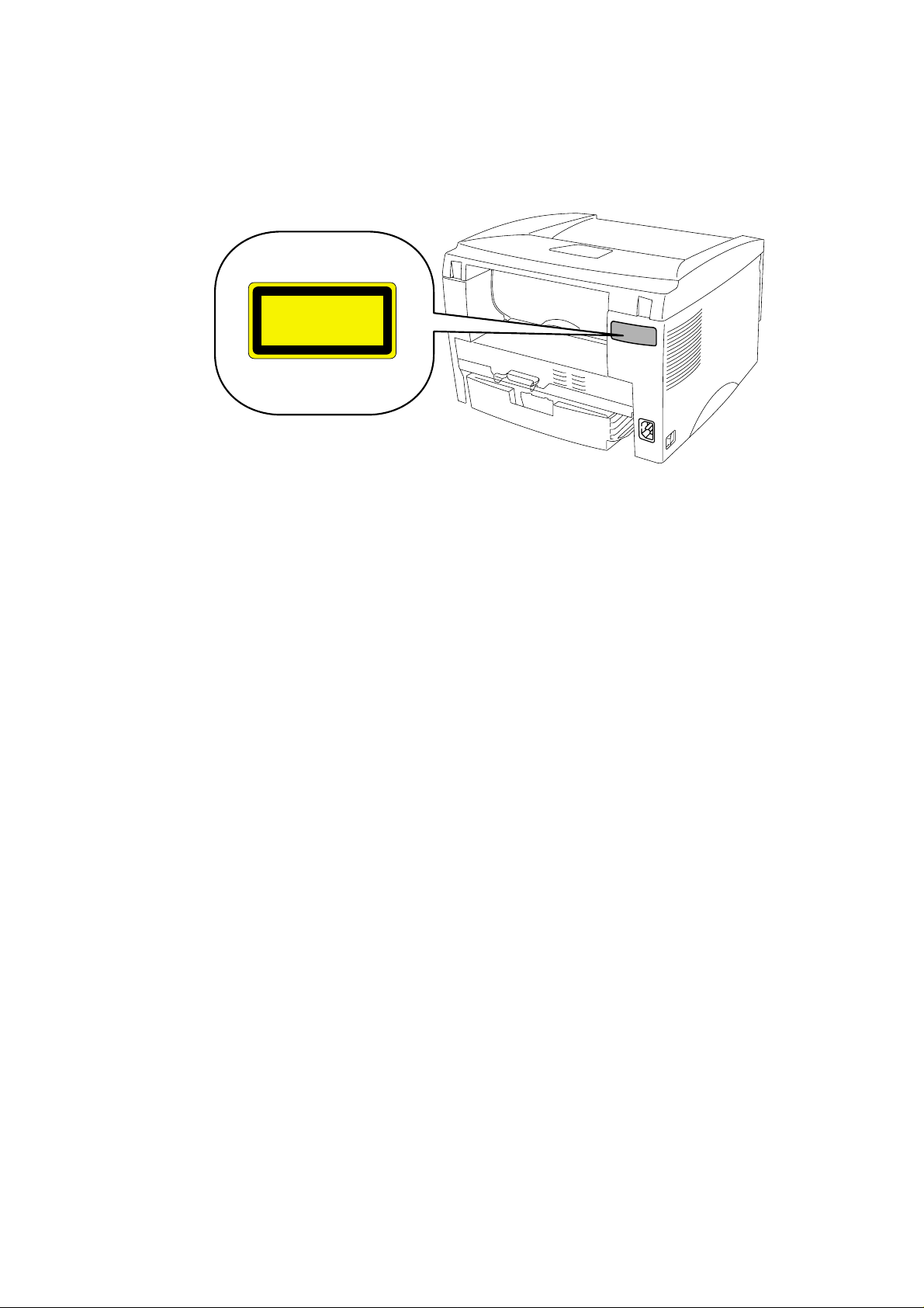
FDA REGULATIONS (110 - 120V MODEL ONLY)
The US Food and Drug Administration (FDA) has implemented regulations for laser
products manufactured on and after August 2, 1976. Compliance is mandatory for
products marketed in the United States. One of the following labels on the back of the
printer indicates compliance with the FDA regulations and must be attached to laser
products marketed in the United States.
The label for Japanese manufactured products
MANUFACTURED: K
BROTHER INDUSTRIES, LTD.
15-1, Naeshiro-cho, Mizuho-ku, Nagoya 467-8561,
Japan.
This product complies with FDA radiation performance
standards, 21 CFR Subchapter J.
The label for Chinese manufactured products
MANUFACTURED: C
BROTHER Corporation (Asia) Ltd.
Shenzen Buji Nan Ling Factory
Gold Garden Ind., Nan Ling Village, Buji, Rong Gang,
Shenzen, CHINA
This product complies with FDA radiation performance
standards, 21 CFR Subchapter J.
Caution
Use of controls, adjustments or performance of procedures other than those specified in
this manual may result in hazardous radiation exposure.
vii
Page 10
REGULATION
IEC 825 (220-240V MODEL ONLY)
This printer is a Class I laser product as defined in IEC 825 specifications. The label
shown below is attached in countries where required.
CLASS 1 LASER PRODUCT
APPAREIL LASER DE CLASSE 1
LASER KLASSE 1 PRODUKT
This printer has a laser diode which emits invisible laser radiation in the Laser Unit. The
Laser Unit should not be opened without disconnecting the two connectors connected with
the AC power supply and laser unit. Since the variable resistor in the laser unit is adjusted
in accordance with the standards, never touch it.
Caution
Use of controls, adjustments or performance of procedures other than those specified in
this manual may result in hazardous radiation exposure.
For Finland and Sweden
LUOKAN 1 LASERLAITE
KLASS 1 LASER APPARAT
Varoitus! Laitteen käyttäminen muulla kuin tässä käyttöohjeessa mainitulla tavalla saattaa
altistaa käyttäjän turvallisuusluokan 1 ylittävälle näkymättömälle lasersäteilylle.
Varning – Om apparaten används på annat sätt än i denna Bruksanvisning specificerats,
kan användaren utsättas för osynlig laserstrålning, som överskrider gränsen för laserklass
1.
viii
Page 11
SAFETY INFORMATION
SAFETY INFORMATION
CAUTION FOR LASER PRODUCT (WARNHINWEIS FUR LASER DRUCKER)
CAUTION: When the machine during servicing is operated with the cover open, the
regulations of VBG 93 and the performance instructions for VBG 93 are
valid.
CAUTION: In case of any trouble with the laser unit, replace the laser unit itself. To
prevent direct exposure to the laser beam, do not try to open the enclosure
of the laser unit.
ACHTUNG: Im Falle von Störungen der Lasereinheit muß diese ersetzt werden. Das
Gehäuse der Lasereinheit darf nicht geöffnet werden, da sonst
Laserstrahlen austreten können.
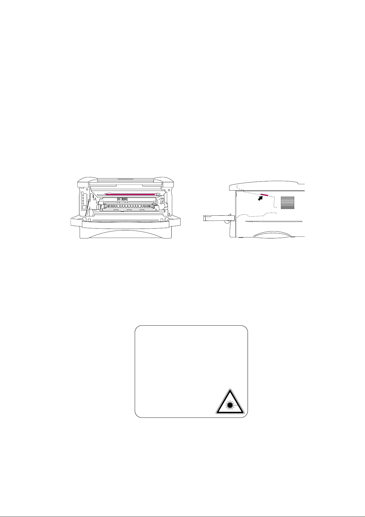
<Location of the laser beam window>
ADDITIONAL INFORMATION
When servicing the optical system of the printer, be careful not to place a screwdriver or
other reflective object in the path of the laser beam. Be sure to take off any personal
accessories such as watches and rings before working on the printer. A reflected beam,
though invisible, can permanently damage the eyes.
Since the beam is invisible, the following caution label is attached on the laser unit.
INVISIBLE LASER RADIATION WHEN OPEN AND INTERLOCK DEFEATED.
CAUTION
ADVARSEL
VARNING
VARO!
ADVARSEL
ATTENTION
VORSICHT
ATENCIÓN
AVOID DIRECT EXPOSURE TO BEAM. CLASS 3B LASER PRODUCT.
USYNLIG LASER STRÅLING NÅR KABINETLÅGET STÅR ÅBENT.
UNGDÅ DIREKTE UDSÆTTELSE FOR STRÅLING. KLASSE 3B LASER.
OSYNLIG LASERSTRÅLNING NÄR DENNA DEL ÄR ÖPPNAD OCH SPÄRRAR
ÄR URKOPPLADE. STRÅLEN ÄR FARLIG. KLASS 3B LASER APPARAT.
AVATTAESSA JA SUOJALUKITUS OHITETTAESSA OLET ALTTIINA
NÄKYMÄTTÖMÄLLE LASERSÄTEILYLLE. ÄLÄ KATSO SÄTEESEEN. LUOKAN
3B LASERLAITE.
USYNLIG LASERSTRÅLING.UNNGÅ DIREKTE KONTAKT MED LASERENHETEN
NÅR TOPPDEKSELET ER ÅPENT. KLASSE 3B LASERPRODUKT.
RADIATIONS LASER INVISIBLES QUANDOUVERT ET VERROUILLAGE ENLEVE.
EVITER EXPOSITIONS DIRECTES AU FAISCEAU. PRODUIT LASER CLASSE 3B.
UNSICHTBARE LASERSTRAHLUNG WENN ABDECKUNG
GEÖFFENT UND SICHERHEITSVERRIEGELUNG
ÜBERBRÜCKT. NICHT DEM STRAHL AUSSETZEN.
SICHERHEITSKLASSE 3B.
RADIACIÓN LASER INVISIBLE CUANDO SE ABRE
LA TAPA Y EL INTERRUPTOR INTERNO ESTÁ
ATASCADO. EVITE LA EXPOSICIÓN DIRECTA
DE LOS OJOS. PRODUCTO LASER CLASE 3B.
ix
Page 12
SAFETY INFORMATION
DEFINITIONS OF WARNINGS, CAUTIONS AND NOTES
The following conventions are used in this service manual:
Indicates warnings that must be observed to prevent possible personal injury.
!
Indicates cautions that must be observed to service the printer properly or prevent damage
to the printer.
NOTE:
Indicates notes and useful tips to remember when servicing the printer.
**Listed below are the various kinds of “WARNING” messages included in this manual.
WARNING
CAUTION:
WARNING
Always turn off the power switch and unplug the power cord from the power outlet
before accessing any parts inside the printer.
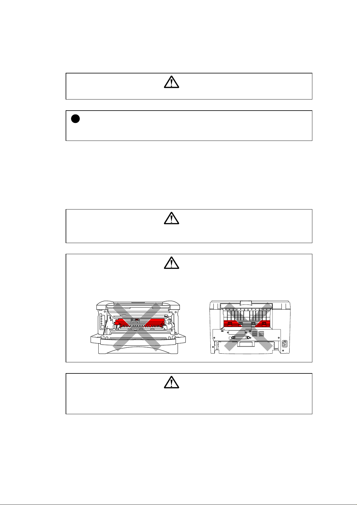
WARNING
Some parts inside the printer are extremely hot immediately after the printer is used.
When opening the front cover or rear cover to access any parts inside the printer,
never touch the red colored parts shown in the following figures.
WARNING
If you analyze malfunctions with the power plug inserted into the power outlet,
special caution should be exercised even if the power switch is OFF because it is a
single pole switch.
x
Page 13

CHAPTER 1 GENERAL
1. FEATURES
This printer has the following features;
High Resolution and Fast Print Speed
<HL-1030>
True 600 x 600 dots per inch (dpi) (GDI mode) with microfine toner and up to 10 pages per
minute (ppm) print speed (A4 or Letter paper).
<HL-1240>
True 600 x 600 dots per inch (dpi) (GDI mode) and true 300 x 300 dots per inch (dpi) (PCL
mode) with microfine toner and up to 12 pages per minute (ppm) print speed (A4 or Letter
paper).
<HL-1250/1270N>
True 600 x 600 dots per inch (dpi) and 1200 x 600 dots per inch (dpi) for graphics with
microfine toner and up to 12 pages per minutes (ppm) print speed (A4 or Letter paper).
CHAPTER 1 GENERAL
Versatile Paper Handling
The printer loads paper automatically from the paper cassette. The paper cassette can hold
A4, letter, B5, Executive A5 and A6 sizes of paper. The manual feed slot allows manual paper
loading sheet by sheet so you can use a variety of types and sizes of paper.
Front Operation
Basic operation of the printer can be controlled from the front panel.
Enhanced Printing Performance and User-Friendly Operation for Windows
The dedicated printer driver for Microsoft Windows 95/98, Windows 3.1 and Windows NT
4.0 are available on the CD-ROM supplied with your printer. You can easily install them into
your Windows
compression mode to enhance printing speed in Windows
system using our installer program. The driver supports our unique
applications and allows you to
choose various printer settings including toner save mode, custom paper size, sleep mode,
gray scale adjustment, resolution, water mark and many layout functions. You can easily
setup these print options through the Printer Setup Menu.
Printer Status Monitor with Bi-directional Parallel Interface
The printer driver can monitor the status of your printer using bi-directional parallel
communications. IEEE-1284 bi-directional parallel printer cable is recommended.
The printer status monitor program can show the current status of your printer. When printing,
the animated dialog box appears on your computer screen to show the current printing
process. If an error occurs, a dialog box will appear to let you know what to correct. If you
have turned on the interactive Help ( Windows 95/98 only) you can get visual guidance on your
PC screen on the actions in the event of certain printer errors.
Quick Print Setup
The Quick Print Setup is a convenient utility to allow you to make changes to frequently used
driver settings easily without having to open the printer properties selection box every time. It
is launched automatically when this printer driver is selected. You can change the settings by
clicking on the icon with the right mouse button.
1-1
Page 14

CHAPTER 1 GENERAL
Enhanced Memory Management
The printer provides its own data compression technology in its printer hardware and the
supplied printer driver software, which can automatically compress graphic data and font data
efficiently into the printer’s memory. You can avoid memory errors and print most full page 600
dpi graphic and text data, including large fonts, with the standard printer memory.
USB Interface (for Windows
98, iMac and Power Macintosh G3 using USB with HL-
1240/1250/1270N only)
The printer can be connected using the Universal Serial Bus (USB) interface to a PC or Mac
which has a USB interface. Drivers that allow you to use the USB port are provided on the
CD-ROM supplied with the printer.
Remote Printer Console Program for DOS (for HL-1240/1250/1270N only)
The utility program, Remote Printer Console (RPC), is available on the CD-ROM supplied with
your printer. When you operate your computer in a DOS (Disk Operating System)
environment, this program allows you to easily change the default settings of the printer such
as fonts, page setup and emulations.
This program also provides a status monitor program, which is a Terminate-and-Stay Resident
(TSR) program. It can monitor the printer status while running in the background and report
the current status or errors on your computer screen.
Popular Printer Emulation Support (for HL-1240/1250/1270N only)
These printers support the following printer emulation modes;
The HL-1240 supports HP LaserJet IIP.
The HL-1250 supports HP LaserJet 6P (PCL6), Epson FX-850 and IBM Proprinter XL.
The HL-1270N supports HP LaserJet 6P (PCL6), PostScript Level 2 language emulation
(Brother BR-Script Level 2), Epson FX-850 and IBM Proprinter XL.
When you use DOS application software or Windows version 3.0 or earlier, you can use any
of these emulations to operate the HL-1250/1270N printers. The printers also support autoemulation switching between HP, Brother BR-Script 2 and Epson or HP, BR-Script 2 and IBM.
If you want to set the printer emulation, you can do it using the Remote Printer Console
Program.
High Resolution Control & Advanced Photoscale Technology (for HL-1250/1270N only)
High Resolution Control (HRC) technology provides clear and crisp printouts. Use this function
to get smooth text print quality.
Advanced Photoscale Technology (APT) enables the printer to print graphics in 256
grayscales, producing nearly photographic quality. Use this function when you want to print
photographic images.
Environment-Friendly
<Economy Printing Mode>
This feature will cut your printing cost by saving toner. It is useful for obtaining draft copies for
proof-reading. You can select from two economy modes, 25% toner saving and 50% toner
saving, through the Windows
printer driver supplied with your printer.
<Sleep Mode (Power Save Mode)>
Sleep mode automatically reduces power consumption when the printer is not in use for a
certain period of time. The printer consumes less than 5W (HL-1030/1240), 6W (HL-1250) or
12W (HL-1270N) when in sleep mode.
<Low Running Cost>
Since the toner cartridge is separate from the drum unit, you need to replace only the toner
cartridge after around 3,000 pages for the standard cartridge and around 6,000 pages for the
optional high-capacity cartridge, which is both cost both effective and ecologically friendly.
1-2
Page 15

CHAPTER 1 GENERAL
Bar Code Print (for HL-1250/1270N only)
The printer can print the following 11 types of bar codes;
Code 39
•
Code 128
•
Interleaved 2 of 5
•
Codabar
•
US-PostNet
•
ISBN
•
UPC-A
•
UPC-E
•
EAN-8
•
EAN-13
•
EAN-128
•
Network Feature (for HL-1270N only)
The Brother printer has built in multi protocol network capability as standard. This allows
multiple host computers to share the printer on a 10/100Mbit Ethernet network. Any users can
print their jobs as if the printer was directly connected to their computer. Users on Windows®
95/98, Windows NT
®
, UNIX, Novell, Apple Macintosh, LAN server and OS/2 Warp server
computer simultaneously can access this printer. For further information, see the Network
User’s Guide supplied with the printer.
1-3
Page 16

CHAPTER 1 GENERAL
(
y)
2. OVERVIEW
<Front View>
Manual feed paper guides
Output tray
Tray extension flap
Control panel
Front cover
Manual feed slot
Paper indicator
Paper cassette
Fig. 1-1
<Rear View>
HL-1030/1240
Rear cover
USB interface connector
for HL-1240 onl
Parallel interface connector
HL-1250/1270N
Network interface
(for HL-1270N only)
Power switch
AC power inlet
Fig. 1-2
Modular jack for
Lower Tray Unit
Rear cover
USB interface
connector
Parallel interface
connector
AC power inlet
Power switch
Fig. 1-3
1-4
Network board
(for HL-1270N only)
10/100BASE TX
Network port
L F A TEST
LED
Test button
Page 17

3. SPECIFICATIONS
3.1 Printing
Print method Electrophotography by semiconductor laser beam scanning
Laser Wave length: 780 nm
Resolution HL-1030: 600 x 600 dots/inch (GDI)
Output: 5mW max
HL-1240: 600 x 600 dots/inch (GDI)
300 x 300 dots/inch (under DOS or other operating
system)
HL-1250: 1200(H) x 600(V) dots/inch (for Windows
graphics)
600 x 600 dots/inch (for Windows
and DOS)
300 x 300 dots/inch (under Apple Macintosh using the
optional RS-100M)
HL-1270N: 1200(H) x 600(V) dots/inch (for Windows
graphics)
600 x 600 dots/inch (for Windows
and DOS)
CHAPTER 1 GENERAL
DIB
DIB
Print quality Normal printing mode
Economy printing mode (up to 25% and 50% toner saving)
Print speed HL-1030: Up to 10 pages/minute
HL-1240/1250/1270N: Up to 12 pages/minute*
(when loading A4 or Letter-size paper from the paper cassette.)
Warm-up Max. 45 seconds at 23°C (73.4°F)
First print 15 seconds
(when loading A4 or Letter-size paper from the paper cassette.)
Print media Toner cartridge
Life expectancy: 3,000 pages/cartridge (Standard cartridge)
6,000 pages/cartridge (High-capacity cartridge)
(when printing A4 or Letter-size paper at 5% print coverage)
Developer Drum unit
Life expectancy: 20,000 pages/drum unit
*NOTE:
Print speed varies depending on the paper size or media type. For details, refer to APPENDIX
3 ‘PRINT SPEEDS WITH VARIOUS SETTINGS’.
1-5
Page 18

CHAPTER 1 GENERAL
3.2 Functions
CPU HL-1030/1240: MB86833 66MHz
HL-1250/1270N: MB86832 66MHz
Emulation HL-1030: Brother Printing Solution for Windows
HL-1240: Brother Printing Solution for Windows
HP LaserJet IIP (PCL level 4)
HL-1250: Brother Printing Solution for Windows
Automatic emulation selection among HP LaserJet 6P
(PCL level 6), EPSON FX-850 or IBM Proprinter XL
HL-1270N: Brother Printing Solution for Windows
Automatic emulation selection among HP LaserJet 6P
(PCL level 6), Brother BR-Script Level 2, EPSON FX850 or IBM Proprinter XL
Printer driver <PCL Driver>
Windows
•
3.1/3.11, Windows 95/98, Windows NT 4.0 driver,
supporting Brother Native Compression mode
Windows
•
3.1/3.11, Windows 95/98 driver, supporting bi-
directional capacity
<PS Driver>
PPD file driver for Windows
95/98 and Windows NT 4.0 driver (for
HL-1270N only)
<Others>
iMac, Power Macintosh G3 with USB printer driver (for HL-
•
1240/1250/1270N only)
Optional Macintosh driver available for System 6.0.7 or higher (for
•
HL-1250 only)
Interface
Bi-directional parallel
•
Universal Serial Bus (USB) (for HL-1240/1250/1270N only)
•
Optional RS-422A/RS-232C serial (RS-100M) available (for HL-
•
1250 only)
10/100 BaseTX Ethernet network interface (for HL-1270N only)
•
Memory HL-1030/1240: 2.0 Mbytes
No memory expansion is possible on these models
HL-1250/1270N: 4.0 Mbytes
Expandable up to 36 Mbytes by installing an
industry standard SIMM*
Control panel 1 button and 4 LEDs
Diagnostics Self-diagnostic program
*NOTE:
The SIMM must have the following specifications;
Type: 72 pin (Both EDO RAM and Fast page mode DRAM can be used.)
Access time: 60 nsec - 80 nsec
Capacity: 1, 2, 4, 8, 16, 32 Mbyte
(Although the 64 Mbyte SIMM can be installed, only 32 Mbyte is effective.)
Height: 35.0 mm (1.38 inches) or less
Output: 32 bit or 36 bit (independent of parity)
1-6
Page 19

3.3 Electrical and Mechanical
Power source U.S.A. and Canada: AC 110 to 120V, 50 Hz/60 Hz
Europe and Australia: AC 220 to 240V, 50 Hz/60 Hz
Power consumption Printing (peak)*: 940 W or less
Printing (average): 340 W or less
Standing by: 80 W or less
Sleep*: 5 W or less (HL-1030/1240)
Noise Printing: 49 dB A or less
Standing by: 27 dB A or less
Temperature Operating: 10 to 32.5°C (50 to 90.5°F)
Non operating: 0 to 40°C (38 to 104°F)
Storage: -20 to 40°C (-4 to 104°F)
Humidity Operating: 20 to 80% (non condensing)
Storage: 10 to 85% (non condensing)
CHAPTER 1 GENERAL
6 W or less (HL-1250)
12W or less (HL-1270N)
Dimensions A4 paper cassette installed: 360 x 370 x 235 mm
(W x D x H) (14.2 x 14.6 x 9.3 inches)
Legal paper cassette installed: 360 x 430 x 235 mm
(14.2 x 16.9 x 9.3 inches)
A4 lower paper cassette installed: 360 x 370 x 345 mm
(HL-1250/1270N only) (14.2 x 14.6 x 13.6 inches)
Legal lower paper cassette installed: 360 x 430 x 345 mm
(HL-1250/1270N only) (14.2 x 16.9 x 13.6 inches)
Weight Approx. 9.2 kg (20.2 lb.) including the drum unit.
Approx. 12.7 kg (27.9 lb.) including the drum unit and Lower Tray unit.
*NOTE:
The peak figure of power consumption is worked out when the halogen heater lamp is
•
turned ON.
The peak figure of power consumption is worked out excluding inrush current value.
•
The peak figure of power consumption is a reference value and should be used internally at
•
Brother offices only.
The power consumption figure quoted for sleep mode is when the fan has stopped.
•
1-7
Page 20

CHAPTER 1 GENERAL
3.4 Network (for HL-1270N only)
Type / Speed 10/100 Base TX Ethernet
Auto speed detection
Protocols
•
TCP/IP
DHCP, BOOTP, RARP, DHCP, NetBIOS over IP
LPR/LPD, Port9100, Custom Port, POP3/SMTP SMB Print
TELNET, SNMP, HTTP, TFTP
Novell IPX.SPX (Bindery/NDS)
•
AppleTalk
•
Management
Web Based Management
•
BRAdmin32 Windows
•
TELNET and Netware Command Console
•
SNMP/MIB II
•
HP JetAdmin / Web JetAdmin compatible
•
based management utility
Firmware update 2MB flash ROM. Use BRAdmin32 when upgrading print server
software or BOOTP, TFTP PUT/GET or IPX for Netware.
Supplied software
BRAdmin32 management utility (for Windows
•
Port driver for Windows
•
LPR port driver (for Windows
95/98/NT 4.0
95/98 only)
95/98/NT 4.0)
NetBIOS port driver
SMTP port driver
3.5 Paper
3.5.1 Feedable paper
(1) Type & size
Feeding source Paper type Paper size
Paper cassette Normal paper
Manual feed slot Normal paper A4, Letter, B5 (JIS/ISO), A5, A6, Executive, Legal
Optional lower
paper cassette
(HL-1250/1270N only)
*NOTE:
Legal-size paper can be printed with the standard paper cassette or the optional lower cassette
for the US and Canada models only.
A4, Letter, B5 (ISO), A5, A6, Executive, Legal*
Transparencies
70-216 x 116-356 mm
(2.75-8.5 x 4.57-14 inches)
Envelopes DL, C5, COM10, Monarch, B5 (ISO)
Organizers J, K, L sizes of DAY-TIMER
Labels A4, Letter
Transparencies A4, Letter
Other sizes 70-216 x 116-356 mm (2.75-8.5 x 4.57-14 inches)
Normal paper
A4, Letter, B5 (ISO), A5, Executive, Legal*
Transparencies
1-8
Page 21
CHAPTER 1 GENERAL
(2) Other paper specifications
<Paper Cassette>
Cut sheet
Basis weight 64 to 105 g/m2 (17 to 28 lb.)
Caliper 0.08 to 0.13 mm (0.003 to 0.005 in.)
Moisture content 4% to 6% by weight
<Manual Feed Slot>
Cut sheet Envelope
Basis weight 64 to 158 g/m2 (17 to 43 lb.) 75 to 90 g/m2 (20 to 24 lb.)
single thickness
Caliper 0.08 to 0.2 mm (0.003 to 0.008 in.) 0.084 to 0.14 mm (0.003 to 0.005 in.)
single thickness
Moisture content 4% to 6% by weight 4% to 6% by weight
(3) Recommended paper
Letter: Xerox 4200 (75 g/m
•
A4: Xerox 80 Premier Paper (80 g/m
•
Label: Avery laser label or equivalent
•
Transparency: 3M CG3300 or equivalent
•
2
)
2
)
CAUTION:
!
When you are choosing print media, be sure to follow the information given below to prevent
any paper jams, print quality problems or printer damage;
It is recommended to use long-grained paper for the best print quality. If short-grained
•
paper is being used, it might be the cause of paper jams.
Use neutral paper. Do not use acid paper to avoid any damage to the drum unit.
•
Avoid using coated paper such as vinyl coated paper.
•
Avoid using preprinted or highly textured paper.
•
It is recommended to use labels or transparencies which are designed for use in laser
•
printers.
Avoid feeding labels with the carrier sheet exposed, or the printer will be damaged.
•
Before loading paper with holes such as organizer sheets, be sure to fan the stack well.
•
Do not use organizer sheets that are stuck together. The glue that is used might caused
•
damaged to the printer.
When printing on the back of pre-printed paper, if the paper is curled, be sure to straighten
•
the paper as much as possible.
Different types of paper should not be loaded at the same time in the paper cassette to
•
avoid any paper jams or misfeeds.
1-9
Page 22
CHAPTER 1 GENERAL
3.5.2 Paper cassette capacity
(1) Maximum load height
Paper cassette:
<Normal paper> Up to 27mm (1.06 inches) in height
<Transparencies> 10 sheets
(2) Paper feed conditions
(250 sheets of 80 g/m
2
A4/Letter paper)
Type Weight Cassette
Normal paper (cut sheet)
Special paper (cut sheet)
3.5.3 Print delivery
(1) Output tray stacking
capacity: Maximum 150 sheets (80 g/m
(2) Straight paper path output at the rear of the printer
capacity: 1 sheet **Thicker paper printing is recommended.
NOTE:
When using the straight paper path feed and the rear output method for thicker paper
•
printing, lift up the rear cover at the rear of the printer.
Face-down: Delivery with the printed face of the paper downwards.
•
Face-up: Delivery with the printed face of the paper upwards.
64 to 80 g/m
158 g/m
2
Labels
Envelopes
Organizers
face-down only
face-up only
Manual feed
(1 sheet)
2
2
)
(250 sheet)
✕
✕
✕
✕
1-10
Page 23
3.6 Printing Area
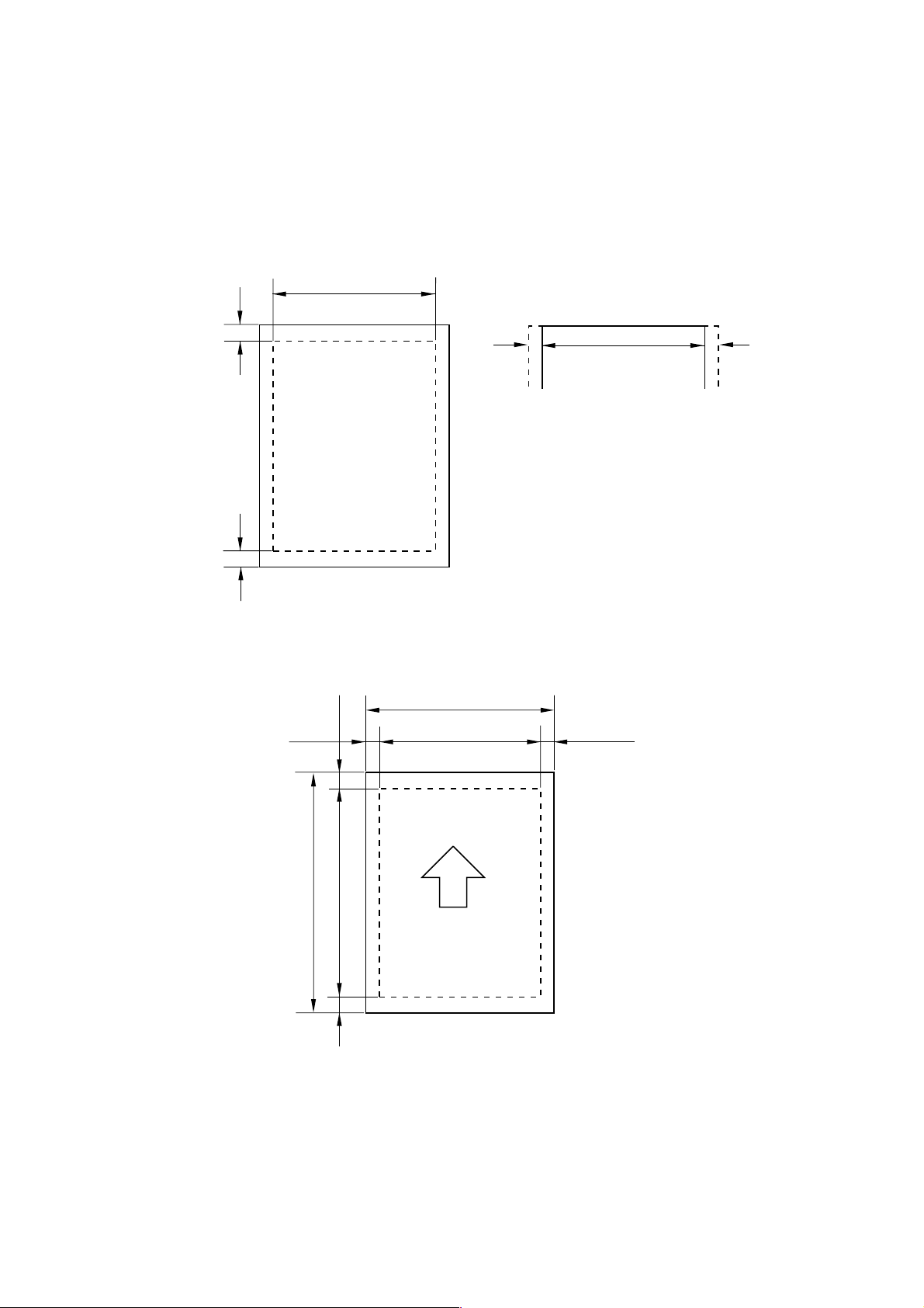
3.6.1 Effective printing area
The effective printing area means the area within which the printing of all the data received
without any omissions can be guaranteed.
CHAPTER 1 GENERAL
(1) Supported by the engine
4.23mm
4.23mm
3.6.2 Print guaranteed area
208mm
(2) Supported by the emulation
25 25
2,400 (80 characters)
NOTE:
The units in the above figure are dot size
•
based on 300 dpi resolution.
25 dots at both sides is for italic characters.
•
F
E
B
D
F
A
CE
The values above vary depending on the paper size. For details, see the table on the next
page.
1-11
Page 24

CHAPTER 1 GENERAL
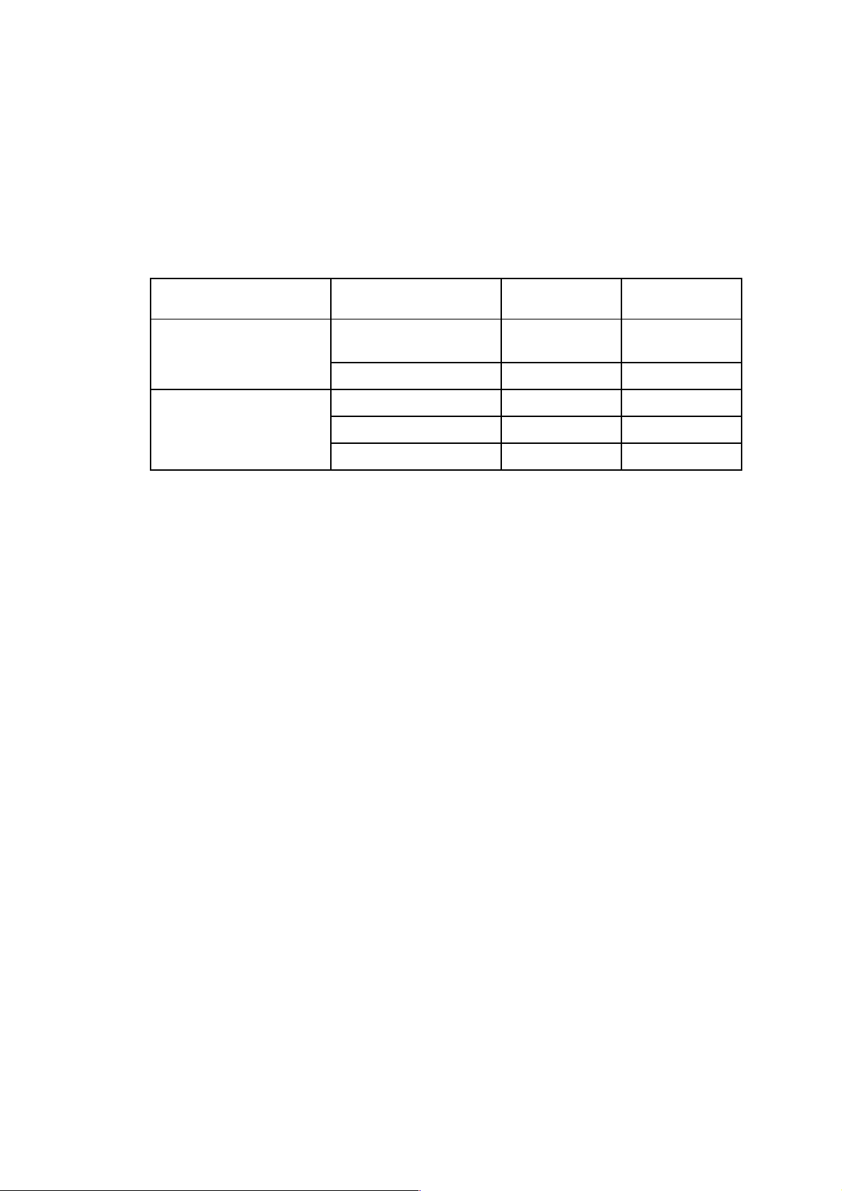
The table below shows the print guaranteed areas for each paper size.
Size A B C D E F
A 4
Letter
Legal
B 5 (ISO)
Executive
A 5
A 6
Organizer
(J size)
Organizer
(K size)
Organizer
(L size)
COM10
MONARCH
C 5
DL
210.0 mm
8.27”
(2,480 dots)
215.9 mm
8.5”
(2,550 dots)
215.9 mm
8.5”
(2,550 dots)
176.0 mm
6.93”
(2,078 dots)
184.15 mm
7.25”
(2,175 dots)
148.5 mm
5.85”
(1,754 dots)
105.0 mm
4.13”
(1,240 dots)
69.85 mm
2.75”
(825 dots)
95.25 mm
3.75”
(1,125 dots)
139.7 mm
5.5”
(1,650 dots)
104.78 mm
4.125”
(1,237 dots)
98.43 mm
3.875”
(1,162 dots)
162 mm
6.38”
(1,913 dots)
110 mm
4.33”
(1,299 dots)
297.0 mm
11.69”
(3,507 dots)
279.4 mm
11.0”
(3,300 dots)
355.6 mm
14.0”
(4,200 dots)
250.0 mm
9.84”
(2,952 dots)
266.7 mm
10.5”
(3,150 dots)
210.0 mm
8.27”
(2,480 dots)
148.5 mm
5.85”
(1,754 dots)
116.0 mm
4.57”
(1,370 dots)
171.45 mm
6.75”
(2,025 dots)
215.9 mm
8.5”
(2,550 dots)
241.3 mm
9.5”
(2,850 dots)
190.5 mm
7.5”
(2,250 dots)
229 mm
9.01”
(2,704 dots)
220 mm
8.66”
(2,598 dots)
203.2 mm
8.0”
(2,400 dots)
203.2 mm
8.0”
(2,400 dots)
203.2 mm
8.0”
(2,400 dots)
164.0 mm
6.46”
(1,936 dots)
175.7 mm
6.92”
(2,025 dots)
136.5 mm
5.37”
(1,612 dots)
93.0 mm
3.66”
(1,098 dots)
56.2 mm
2.21”
(675 dots)
86.78 mm
3.42”
(975 dots)
131.23 mm
5.17”
(1,500 dots)
92.11 mm
3.63”
(1,087 dots)
85.7 mm
3.37”
(1,012 dots)
150.0 mm
5.9”
(1,771 dots)
98.0 mm
3.86”
(1,157 dots)
288.5 mm
11.36”
(3,407 dots)
270.9 mm
10.67”
(3,200 dots)
347.1 mm
13.67”
(4,100 dots)
241.5 mm
9.5”
(2,852 dots)
258.2 mm
10.17”
(3,050 dots)
201.5 mm
7.93”
(2,380 dots)
140.0 mm
5.51”
(1,654 dots)
107.5 mm
4.23”
(1,270 dots)
162.98 mm
6.42”
(1,925 dots)
207.43 mm
8.17”
(2,450 dots)
232.8 mm
9.16”
(2,750 dots)
182.0 mm
7.16”
(2,150 dots)
220.5 mm
8.68”
(2,604 dots)
211.5 mm
8.33”
(2,498 dots)
3.4 mm
0.13”
(40 dots)
6.35 mm
0.25”
(75 dots)
4.23 mm
0.17”
(50 dots)
6.35 mm
0.25”
(75 dots)
6.01 mm
0.24”
(71 dots)
6.35 mm
0.25”
(75 dots)
6.01 mm
0.24”
(71 dots)
NOTE:
The paper sizes indicated here should conform to the nominal dimensions specified by JIS.
•
A4 paper must accommodate 80 characters printed in pica pitch (203.2 mm).
•
The dot size is based on 300 dpi resolution.
•
Organizer is not supported by any printer emulations (commands).
•
1-12
Page 25

CHAPTER 2 INSTALLATION AND BASIC OPERATION
CHAPTER 2 INSTALLATION AND BASIC OPERATION
1. CONDITIONS REQUIRED FOR INSTALLATION
1.1 Power Supply
• The source voltage must stay within ±10% of the rated voltage shown on the rating plate.
• The power cord, including extensions, should not exceed 5 meters (16.5 feet).
• Do no share the same power circuit with other high-power appliances, particularly an air
conditioner, copier or shredder. If it is unavoidable that you must use the printer with these
appliances, it is recommended that you use an isolation transformer or a high-frequency
noise filter.
• Use a voltage regulator if the power source is not stable.
1.2 Environment
• The printer should be installed near a power outlet, which is easily accessible.
• The room temperature is maintained between 10°C and 32.5°C. The relative humidity is
maintained between 20% and 80%.
• The printer should be used in a well ventilation room.
• Place the printer on a flat, horizontal surface.
• Keep the printer clean. Do not place the printer in a dusty place.
• Do not place the printer where the ventilation hole of the printer is blocked. Keep
approximately 100 mm (4 inches) between the ventilation hole and the wall.
• Do not place the printer where it is exposed to direct sunlight. Use a blind or a heavy
curtain to protect the printer from direct sunlight when the printer is unavoidably set up near
a window.
• Do not place the printer near devices that contain magnets or generate magnetic fields.
• Do not subject the printer to strong physical shocks or vibrations.
• Do not expose the printer to open flames or salty or corrosive gasses.
• Do not place objects on top of the printer.
• Do not place the printer near an air conditioner.
• Keep the printer horizontal when carrying.
• Do not cover the slots in the side cover.
1.3 System Requirements for Brother Printer Solution for Windows
Check the following system requirements to setup and operate the printer using Brother
Printing Solution for Windows
• IBM PC or compatible with 80486 SX or higher microprocessor
• 10MB of space available on your hard disk for the printer driver and all fonts.
• Microsoft Windows
:
3.1/3.11, Windows 95/98 or Windows NT 4.0
2-1
Page 26
CHAPTER 2 INSTALLATION AND BASIC OPERATION
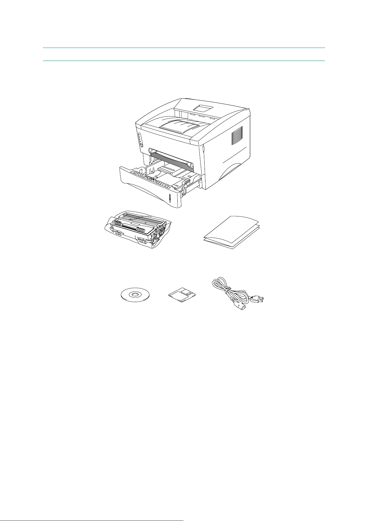
2. UNPACKING
When unpacking the printer, check to see that all of the following components are included in
the carton.
Paper cassette
Printer
Drum unit
(with Toner cartridge included)
CD-ROM
Floppy disk
Fig. 2-1
NOTE:
Components may vary depending on the country.
Documents
AC cord
2-2
Page 27
3. INSTALL THE PRINTER
You need to implement hardware setup and driver installation to use the printer.
Firstly, identify the Operating System on your computer. Then, purchase the appropriate
interface cable (parallel or USB) for your computer.
The installation programs for the hardware setup and driver installation are contained on the
supplied CD-ROM.
CHAPTER 2 INSTALLATION AND BASIC OPERATION
If you do not have a CD-ROM drive, you can install the printer driver from the supplied floppy
disk. (See Subsection 3.2 ‘For Windows
3.1 For Windows® Users
(1) Turn on your PC power. Close all the applications running on your PC.
(2) Insert the supplied CD-ROM into the CD-ROM drive.
(3) The opening screen will appear automatically in Windows
NOTE:
If the opening screen does not appear;
•
Click
(If your CD-ROM drive is not D, type the correct drive letter instead of “D”.)
In Windows 3.1;
Click the File menu in the Program Manager screen and select
in the command line box and click OK. (If your CD-ROM drive is not D, type the correct
drive letter instead of “D”.)
The setup screens shown below are based on the HL-1240 model. They vary depending
•
on the model.
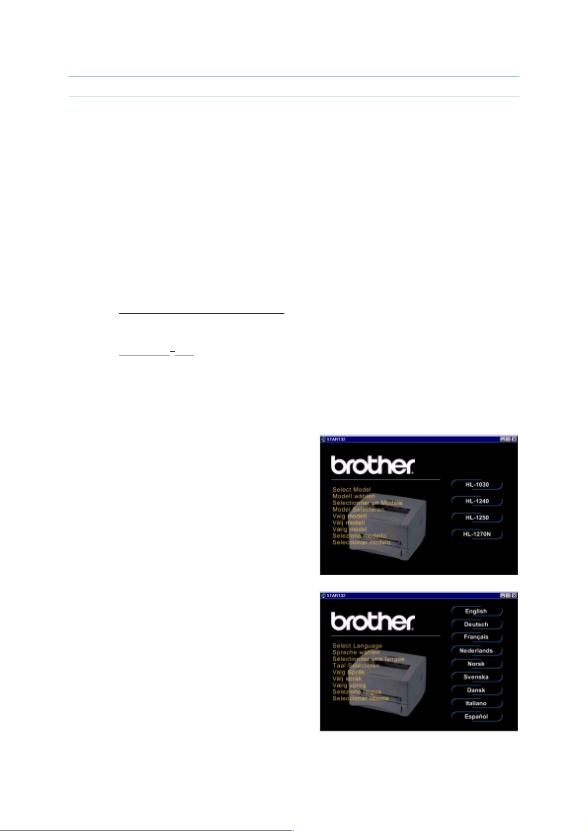
(4) Select the model of your printer.
Start
and select
. Then, type
Run
®
Users with No CD-ROM Drive’.)
95/98/NT4.0.
D:\START
in the command line box and click OK.
Run
. Then, type
D:\START
(5) Select the language you want, then follow
the instructions on the screen.
2-3
Fig. 2-2
Fig. 2-3
Page 28
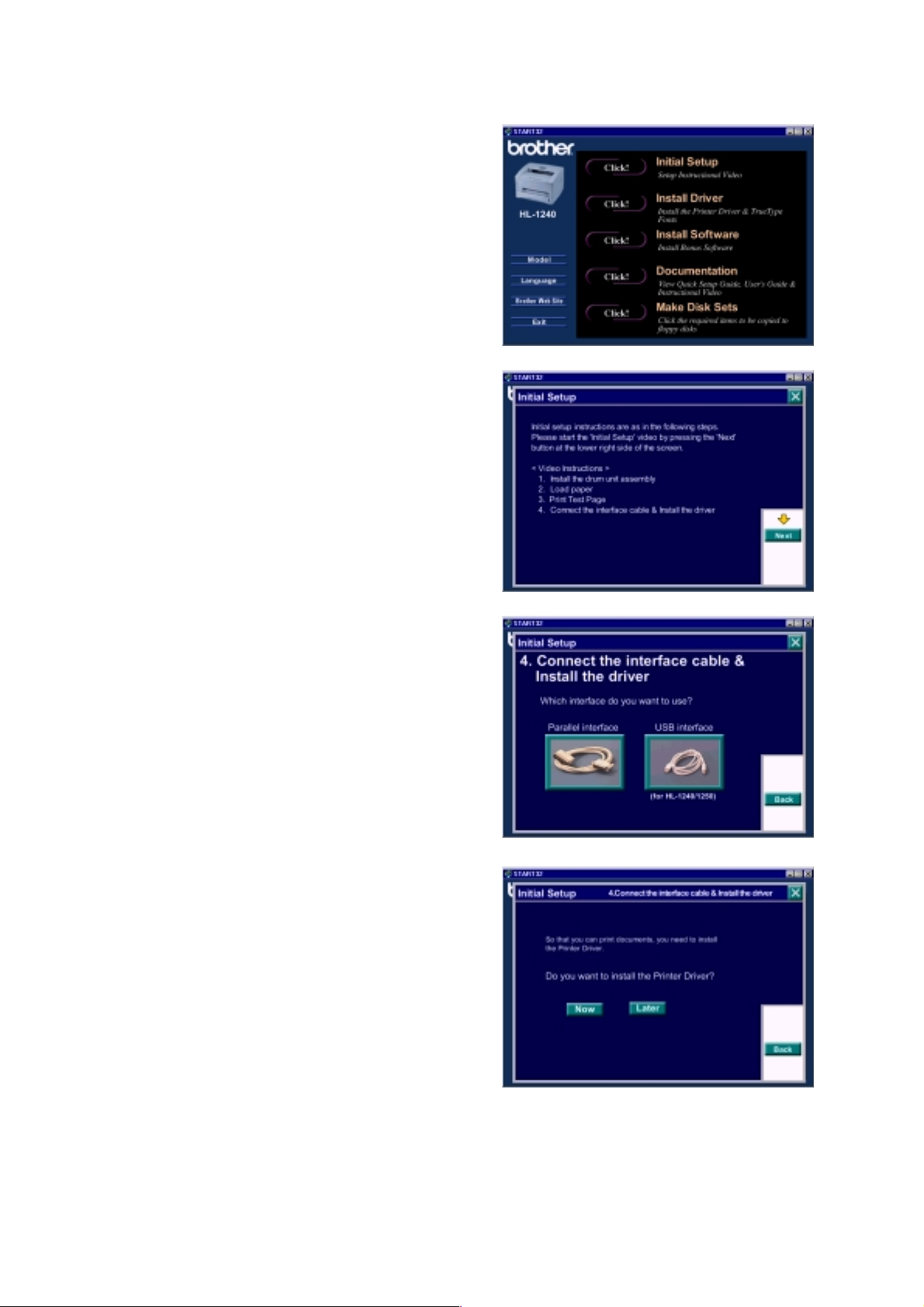
CHAPTER 2 INSTALLATION AND BASIC OPERATION
(6) Click the
Initial Setup
button.
(7) You can view the Initial Setup operations
in the video movie.
Fig. 2-4
(8) Click the interface cable you are going to
use, Parallel or USB.
(9) If you click the
button, you can
NOW
install the printer driver immediately.
(10) After the printer driver has been installed,
the HL-1030, HL-1240, HL-1250 or HL1270N window will appear. Follow the onscreen messages to complete the
installation.
Fig. 2-5
Fig. 2-6
Fig. 2-7
If your printer is connected using a parallel interface cable, the setup is now completed. If you
want to connect your printer using a USB interface cable, refer to Subsection 3.3 ‘Using the
USB Interface (For Windows
98 only)’.
2-4
Page 29
3.2 For Windows® Users with No CD-ROM Drive
If you do not have a CD-ROM drive, setup the printer following the steps below, then install the
printer driver from the floppy disk.
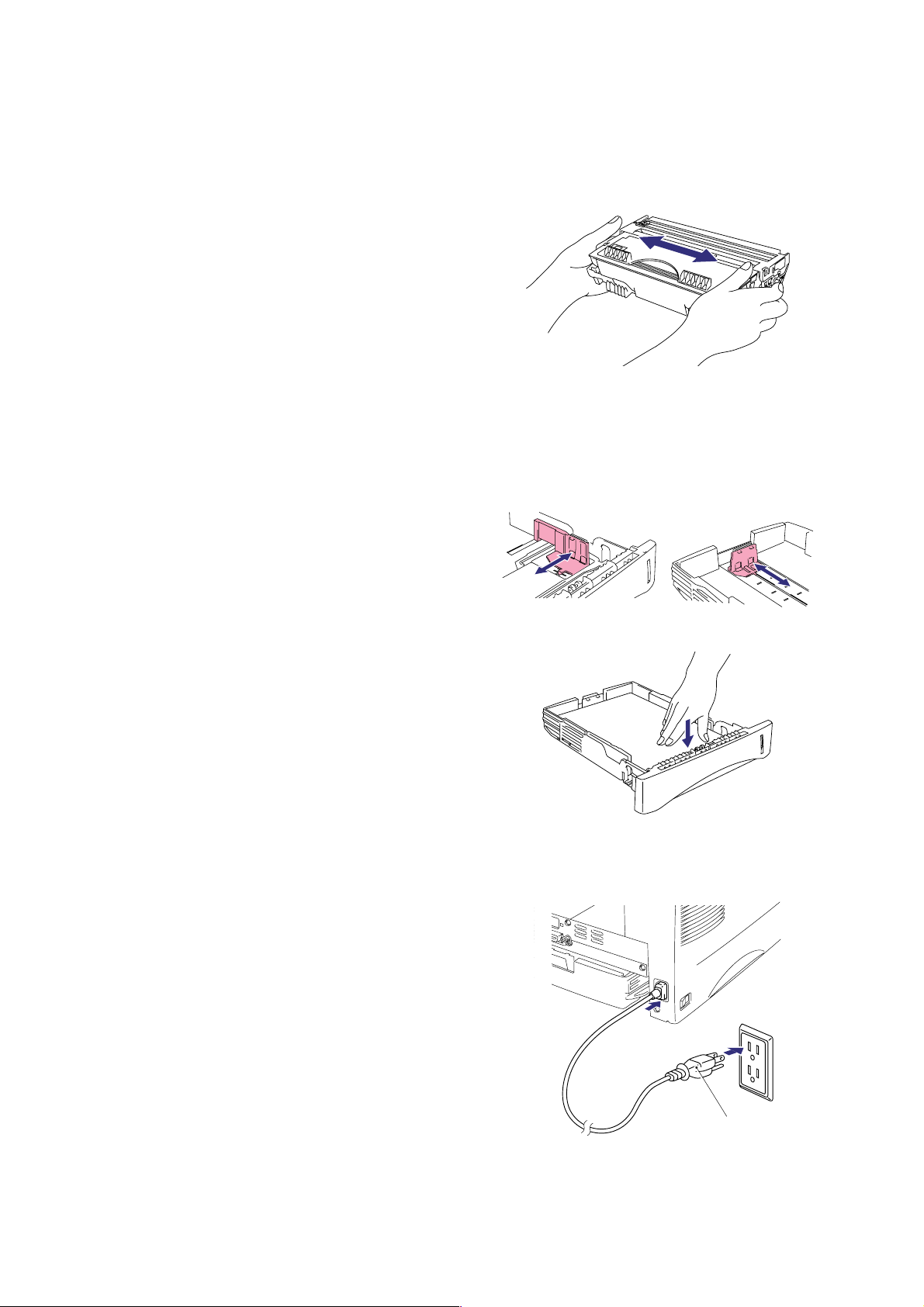
3.2.1 Install the drum unit
(1) Open the front cover.
(2) Unpack the drum unit assembly and rock
it from side to side 5 or 6 times to
distribute the toner evenly inside the
cartridge. (Fig. 2-8)
(3) Install the drum unit into the printer until it snaps into place and close the front cover.
3.2.2 Load paper
(1) Pull the paper cassette completely out of the printer.
(2) Slide the paper guides to the paper size
you want until they snap into a slot. (Fig.
2-9)
CHAPTER 2 INSTALLATION AND BASIC OPERATION
Fig. 2-8
(3) Load paper into the paper cassette.
Check that paper is flat placed. (Fig. 2-
10) Paper should be loaded up to the
lines on the sliding guide.
(4) Re-install the paper cassette into the
printer.
3.2.3 Print a test page
(1) Check that the power switch is off.
(2) Connect the AC power cord to the printer.
(3) Plug the AC power cord into an AC outlet,
then turn on the power switch. (Fig. 2-11)
Fig. 2-9
Fig. 2-10
2-5
AC power cord
Fig. 2-11
Page 30
CHAPTER 2 INSTALLATION AND BASIC OPERATION
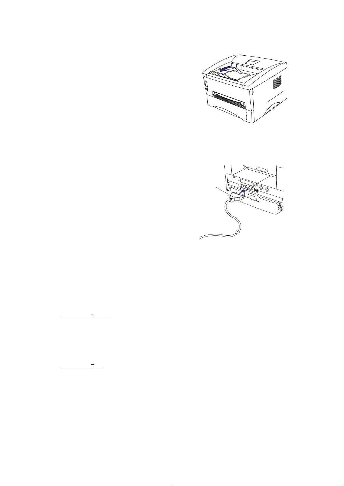
(4) Extend the tray extension flap. After the
printer has warmed up the Ready LED
changes from blinking to lit. (Fig. 2-12)
(5) Press the control panel button. The
printer will print a test page. Check the
test page printed correctly.
3.2.4 Connect the printer and the computer
(1) Turn off the power switch.
(2) Connect the parallel interface to the
computer, then connect it to the printer.
(Fig. 2-13)
(3) Use the clips on the printer connector to
secure the parallel interface cable.
(4) Turn on the printer power switch.
Fig. 2-12
Parallel interface
cable
3.2.5 Install the printer driver from floppy disk
(1) Turn on the computer power. If the “Add New Hardware Wizard” window appears, click
the
Cancel
button.
(2) Insert the supplied floppy disk into the floppy disk drive.
(3) Install the printer driver using the Setup.exe file.
In Windows
i) Click the
95/98
button and select
Start
Run
.
ii) Type A:\SETUP and click OK. (If your floppy disk drive is not A, insert the correct drive
letter instead of ‘A’.)
iii) Follow the instructions that appear on the screen.
In Windows
3.1
i) Click File menu in the Program Manager screen and select
ii) Type A:\SETUP click OK. (If your floppy disk drive is not A, insert the correct drive letter
instead of ‘A’.)
iii) Follow the instructions that appear on the screen.
Run
Fig. 2-13
.
2-6
Page 31

CHAPTER 2 INSTALLATION AND BASIC OPERATION
3.3 Using the USB Interface (for Windows
For the HL-1240/1250/1270N printers, the USB interface cable can be connected between the
printer and PC. Prepare the printer to use the USB interface following the steps below;
3.3.1 Connect the USB interface cable
(1) Check that the printer power switch is on.
(2) Connect the USB interface cable to the
computer, then connect it to the printer.
(Fig. 2-14)
3.3.2 Install the USB driver
98 only)
USB interface
cable
Fig. 2-14
(1) The “Add New Hardware Wizard” window
will appear. Click the
Next
button.
(2) Select “Search for the best driver for your
device.” Click the
Next
button.
Fig. 2-15
2-7
Fig. 2-16
Page 32
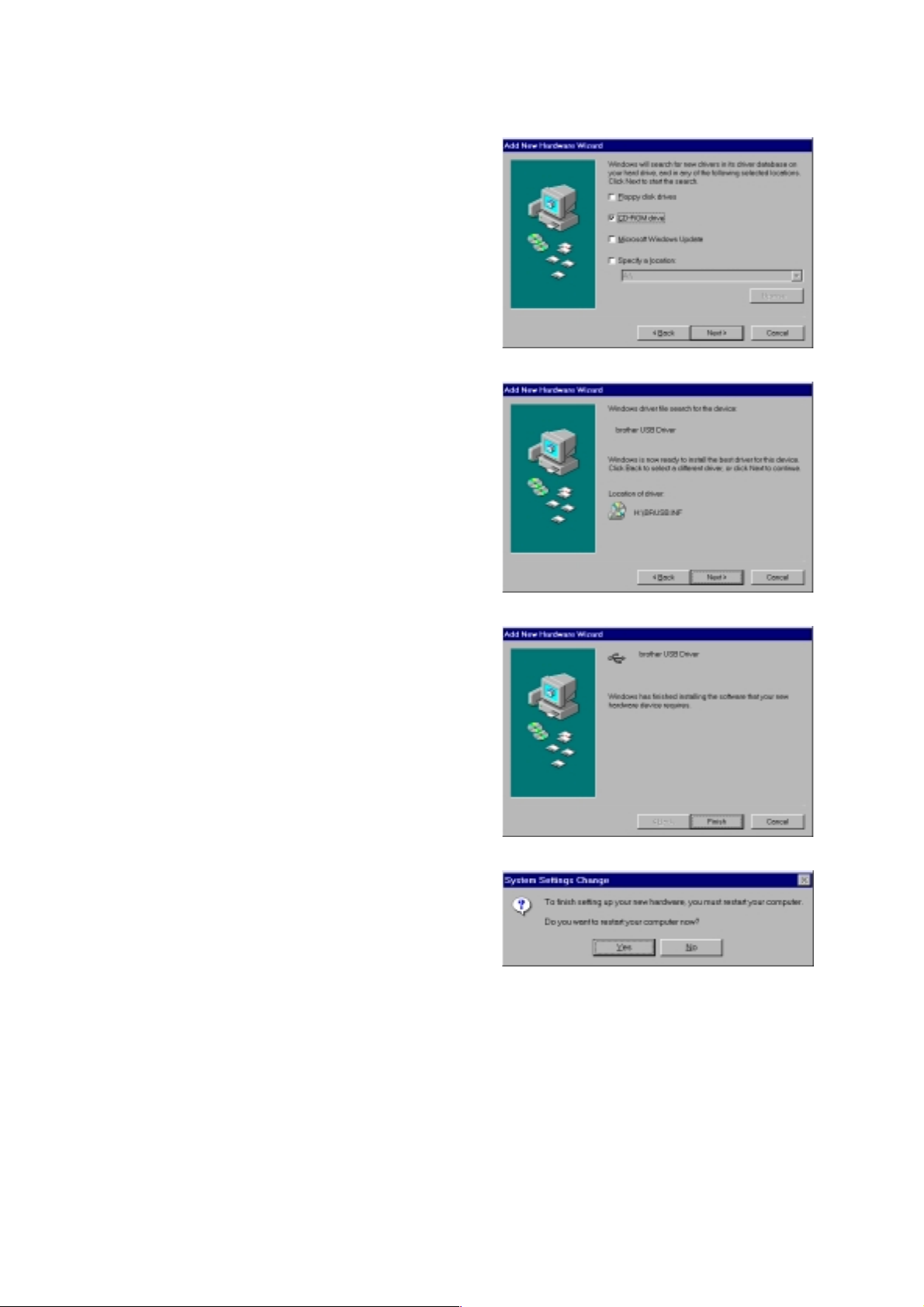
CHAPTER 2 INSTALLATION AND BASIC OPERATION
(3) Insert the supplied CD-ROM into the CD-
ROM drive and select “CD-ROM drive”.
Click the
Next
button.
Fig. 2-17
(4) Click the
will be installed.
(5) Click the
button, then the USB driver
Next
button.
Finish
Fig. 2-18
(6) Click the
start.
button, then your PC will re-
Yes
Fig. 2-19
Fig. 2-20
2-8
Page 33
3.3.3 Set the PC printer port
Your PC printer port has to be set to “USB port”.
CHAPTER 2 INSTALLATION AND BASIC OPERATION
(1) Click the
button and select Printers in Settings.
Start
(2) Select your printer model icon in Printers so that the printer icon is highlighted.
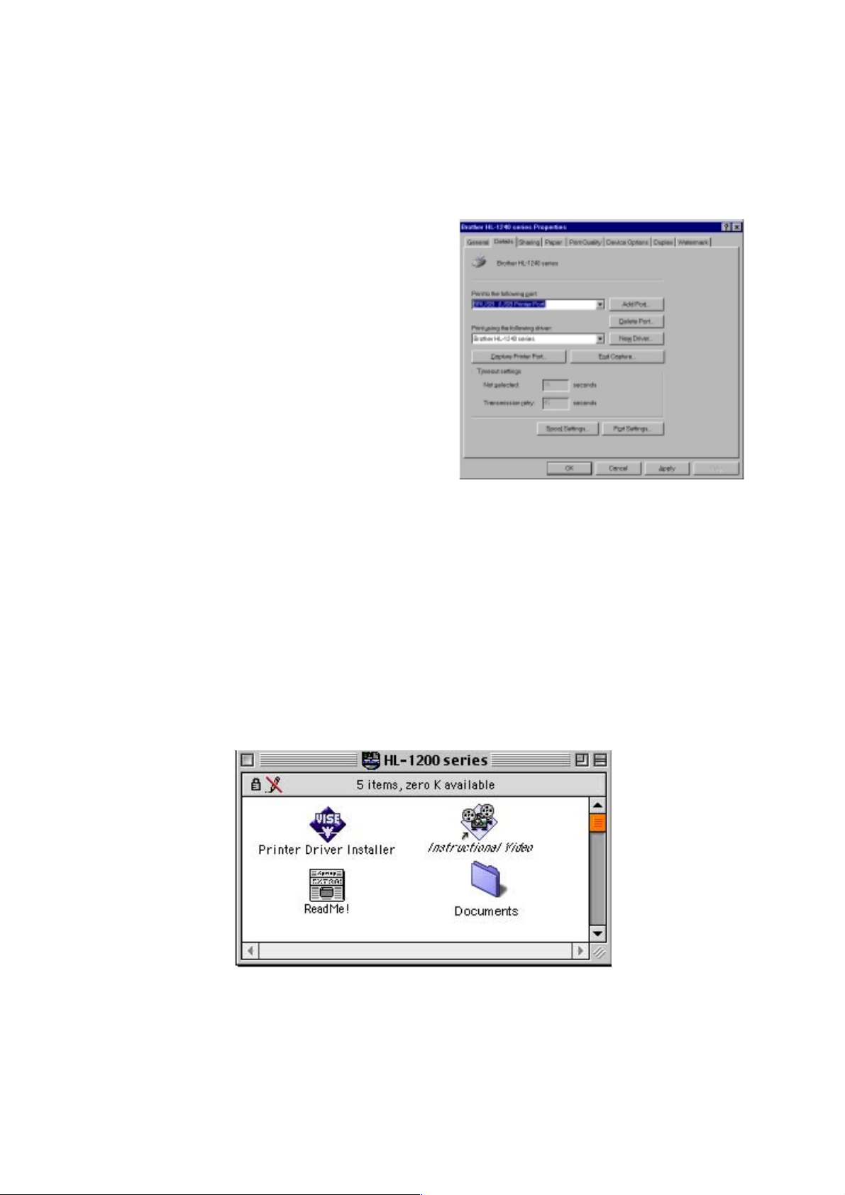
(3) Select Properties from the File menu, then click the Details tab.
(4) Select
BRUSB: (USB Printer Port)
in the
“Print to the following port” box. (Fig. 2-
21)
(5) Click the OK button to close the
Properties dialog box. The setup is now
completed.
Fig. 2-21
NOTE:
Both the parallel cable and USB interface cable can be connected to the printer at the same
time.
3.4 For Macintosh (iMac and Power Macintosh) with USB Users Only
When you use the HL-1240/1250/1270N printer with Macintosh using USB, setup the printer
following the Initial Setup instructions on the supplied CD-ROM.
(1) Turn on the computer power, then insert the CD-ROM into the CD-ROM drive. The
window shown below will appear automatically.
Fig. 2-22
(2) Click the “Instructional Video” icon in the window above to view the Initial Setup operations
in the video movie.
(3) Click the “Printer Driver Installer” icon in the window above to install the printer driver.
2-9
Page 34
CHAPTER 2 INSTALLATION AND BASIC OPERATION
4. PAPER HANDLING
The printer provides two types of paper loading method; paper cassette and manual feed slot.
4.1 Load Paper into the Paper Cassette
You can load normal paper and transparencies into the paper cassette. If you load paper into
the paper cassette, the printer automatically feeds paper sheet by sheet and ejects the printed
page into the output tray.
For the details on cassette loading, refer to Subsection 3.2.2 ‘Load Paper’ in this chapter and
Subsection 3.5 ‘Paper’ in CHAPTER 1.
4.2 Load Paper Manually
You can feed envelopes, labels and organizers as well as normal paper and transparencies
into the manual feed slot. (For details on feedable paper, see Subsection 3.5 ‘Paper’ in
CHAPTER 1.)
When using the manual feed slot, follow the steps below;
(1) Select the manual feed mode in the printer driver, and send the print data to the printer.
NOTE:
A ‘NO PAPER’ message is shown in the status monitor until a sheet of paper is inserted into
the manual feed slot.
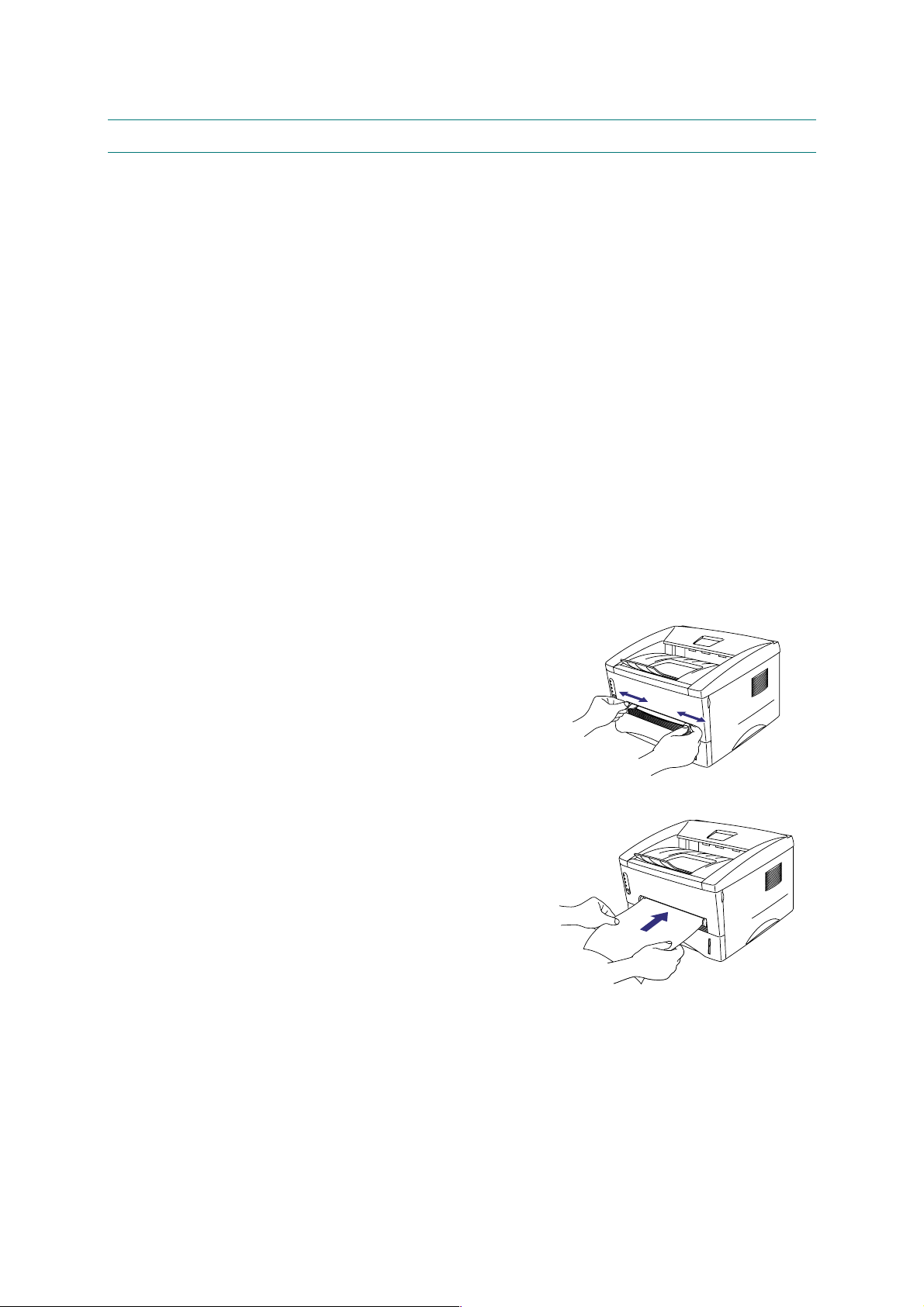
(2) Set the width of the manual feed slot paper
guides using both hands to the paper width to be
used. (Fig. 2-23)
Fig. 2-23
(3) Insert the paper into the manual feed slot with
both hands until the front edge of the paper
touches the paper feed roller.
(4) Hold the paper in this position until the printer
feeds the paper a short distance, then let go of
the paper. (Fig. 2-24)
Fig. 2-24
(5) After the printer ejects the printed page, insert the next sheet of paper as in the previous
step. The printer will wait until you insert the next sheet of paper. Repeat this as necessary
for the number of pages you need to print.
NOTE:
It is recommended to remove printed pages immediately after printing if the output tray
extension flap is not extended.
2-10
Page 35

CHAPTER 2 INSTALLATION AND BASIC OPERATION
The printer has a
the rear cover is lifted up. Use this paper feed and output method when printing on thicker
paper or card.
(1) Select the manual feed mode in the printer
driver.
(2) Lift up the rear cover at the rear of the printer.
(Fig. 2-25)
(3) Send the print data to the printer.
(4) Follow Steps (3) to (4) in the previous page to
load paper.
(5) Close the rear cover of the printer.
CAUTION:
!
Remove each sheet immediately after printing. Stacking the sheets may cause curl or media
feed jams.
straight paper path
from the manual feed slot to the rear of the printer when
4.3 Two Side Printing (Manual Duplexing)
The supplied printer driver allows you to do manual duplex printing.
When using the manual duplex function, note the following information;
Fig. 2-25
CAUTION:
!
If the paper is too thin, it may cause wrinkling.
•
If paper is curled, straighten it and then set it into the paper cassette.
•
The paper type should be regular paper. Do not use bond paper.
•
When setting paper into the paper cassette, empty the cassette first, then insert the printed
•
paper only, printed side face up. (Do not add the printed paper onto the top of the unprinted
paper stack.)
If the paper is not feeding correctly, the paper might be curled. Remove the paper and
•
straighten it.
4.3.1 To print on both sides of the paper from the paper cassette
(1) Select the required manual duplex printing mode from the driver.
(2) The printer will automatically print all the even numbered pages on one side of the paper
first.
(3) Remove the printed even numbered pages from the output tray.
(4) Re-insert them into the paper cassette, loading
the paper with the side to be printed (blank side)
face down, and the top edge toward you. Follow
the instructions on the computer screen. (Fig. 2-
26)
(5) The printer will now automatically print all the
odd pages on the reverse side of the paper.
2-11
Fig. 2-26
Page 36

CHAPTER 2 INSTALLATION AND BASIC OPERATION
4.3.2 To print on both sides of the paper from the manual feed slot
CAUTION:
!
Before re-inserting the sheets, straighten them, or paper feed errors will occur.
•
The use of very thin or very thick paper is not recommended.
•
When the manual duplex function is used, it is possible that paper jams may occur or print
•
quality may not be satisfactory.
(1) Select the required manual duplex printing mode and manual feed mode from the driver.
(2) Using both hands, insert the paper into the manual feed slot with the side to be printed
first facing upwards. Follow the instructions on the computer screen.
(3) Repeat action (2) until you have printed all the even numbered pages.
(4) Remove the printed even numbered pages from the output tray
(5) Re-insert them in order into the manual feed slot,
loading the paper with the side to be printed
(blank side) face up, and the top edge towards
the printer. Follow the instructions on the
computer screen. (Fig. 2-27)
(6) Repeat action (5) until you have printed all the
odd numbered pages on the reverse side of the
paper.
Fig. 2-27
2-12
Page 37

5. CONTROL PANEL OPERATION
There are four LEDs and a button on the control panel. The LEDs indicate the printer status,
and pressing the button enables several functions in the printer.
LEDs
CHAPTER 2 INSTALLATION AND BASIC OPERATION
Drum
Ready
Paper
Alarm
Toner
Data
Control Panel Button
5.1 Ready (Paper) LED Indications
The Ready LED indicates the current status of the printer.
LED Printer status
OFF The power switch is off, or the printer is in sleep mode.
If the printer is in sleep mode, it will wake up automatically when it
receives data or when you press the control panel button.
Blinking <Blinking at 1 second intervals>
The printer is warming up.
<Blinking at 2 seconds intervals>
The printer is cooling down and stops printing until the internal
temperature of the printer lowers.
ON The printer is ready to print.
This LED also works as the Paper LED with the Alarm LED. They blink simultaneously to
indicate a paper error. See Subsection 2.1 ‘Operator Calls’ in CHAPTER 6 for details.
Error Action
Fig. 2-28
Paper jam Clear the paper jam and press the panel button if the printer
does not automatically resume printing.
No paper Load paper in the printer and press the panel button.
Misfeed Re-install the paper and press the panel button.
2-13
Page 38

CHAPTER 2 INSTALLATION AND BASIC OPERATION
5.2 Data (Toner) LED Indications
The Data LED indicates the current status of the print data process.
LED Printer status
OFF The printer has no print data.
Blinking The printer is receiving data from the computer or the printer is
processing data in memory.
ON Print data remains in the printer memory. If the Data LED is on for a
long period of time and nothing has printed, you need to press the
button to print the remaining data.
This LED also works as the Toner LED with the Alarm LED. They blink simultaneously to
indicate a toner error. See also Subsection 2.1 ‘Operator Calls’ in CHAPTER 6 for details.
Error Action
Toner low Indicates that the toner cartridge is nearly empty. Purchase a
new toner cartridge ready for when the ‘Toner empty’ error is
indicated.
Toner empty Replace the toner cartridge with a new one.
5.3 Drum LED Indications
The Drum LED indicates the drum unit is nearly at the end of its life.
LED Printer status
OFF The drum unit can be used.
ON The drum unit is nearly at the end of its life. It is recommended to
obtain a new drum unit to replace the current one.
5.4 Alarm LED Indications
The Alarm LED blinks (with no other LEDs) to indicate a printer error status such as “cover
open” or “memory full”.
If any other error occurs, the printer indicates the error by blinking the Alarm LED with another
LED or by printing an error report. Refer to Subsection 2.2 ‘Service Calls’ in CHAPTER 6.
2-14
Page 39

5.5 Control Panel Button Operations
The control panel button is used for the following purposes depending on the situation.
Operation Description
Cancel printing If the button is pressed during printing, the printer immediately stops
printing and ejects the paper.
Wake-up If the printer is in sleep mode, pressing the button wakes it up into the
ready status. It will take up to 45 seconds for the printer to go into the
ready status.
Form feed If the Data LED is on, press the button. The printer prints any data
remaining in the printer memory.
Error recovery If an error occurs, the printer will recover from some errors automatically.
If the error does not clear automatically, press the button to clear the error
and continue printer operation.
Reprint function You can reprint a print job without sending it from the computer again.
When you press the button with the Data LED off, the printer reprints the
last job you printed if the whole job can be kept in printer memory. If the
print job is too large or there is insufficient memory, the last page only will
be reprinted.
CHAPTER 2 INSTALLATION AND BASIC OPERATION
5.6 Other Control Features
The printer has the following useful features;
5.6.1 Sleep mode
When the printer does not receive data for a certain period of time (timeout), it enters sleep
mode. The default timeout is 5 minutes and it is automatically adjusted to the most suitable
time-out setting depending on the frequency of your printer use (Intelligent Sleep Mode).
While the printer is in sleep mode, all the LEDs are off and it is as if it was turned off, but the
printer can still receive data from the computer. Receiving a print file or document
automatically wakes up the printer to start printing. Pressing the button also wakes up the
printer.
NOTE:
When the printer goes into sleep mode, the fan will not stop until the printer engine has
•
cooled down. The fan running time varies depending on the sleep mode timeout because
the fan running conditions are defined as follows;
1) The fan runs for 10 minutes whenever printing finishes.
2) The fan runs while the printer is in ready status.
3) The fan runs for at least 5 minutes after the printer goes into sleep mode.
(EX: If the timeout is 5 minutes, the fan will be running for 5 minutes after the printer goes
into sleep mode.)
Sleep mode allows the print engine to cool, so the temperature of the room and how long
•
the printer has been in sleep mode affects the warm-up time. This warm-up time can take
up to 45 seconds. The Ready LED blinks to indicate that the printer is warming up.
You can change the timeout for the sleep mode with the supplied printer driver (all models)
•
or Remote Printer Console program. The time-out setting is in the range of 1 to 15 minutes.
Refer to the Help section in the printer driver or RPC program for more information about
the sleep mode setting.
2-15
Page 40

CHAPTER 2 INSTALLATION AND BASIC OPERATION
5.6.2 Test print mode
The printer incorporates various test print modes. The printer enters into each test print mode
by panel button operation.
For details on test print mode, see Subsection 10.1 ‘Test Print Mode’ in CHAPTER 6.
2-16
Page 41
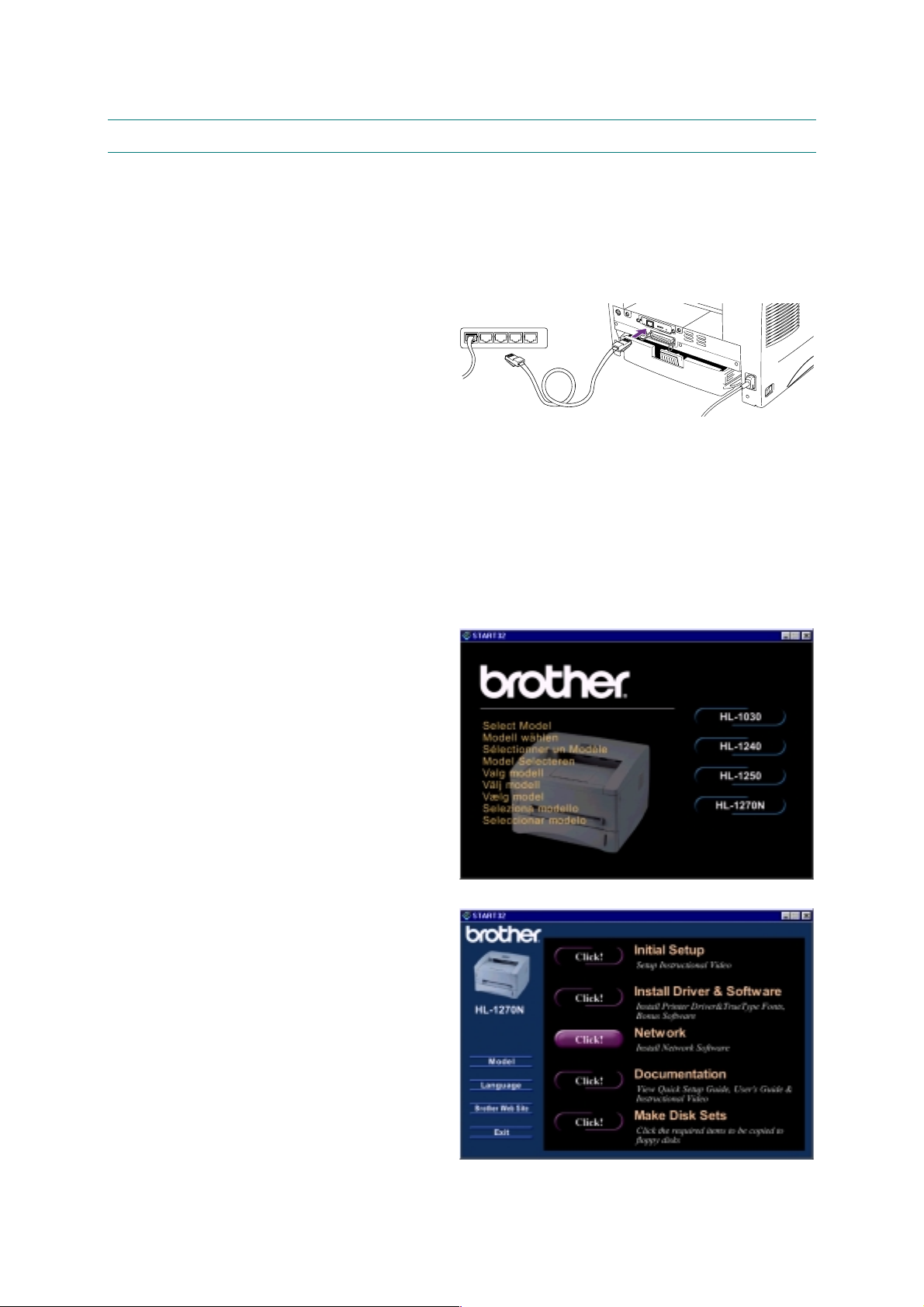
CHAPTER 2 INSTALLATION AND BASIC OPERATION
6. NETWORK BOARD OPERATION (FOR HL-1270N ONLY)
The network board installed in the back of the printer allows you to share the printer on a
network.
6.1 Preparing the BR-net Board
6.1.1 Connect the Ethernet cable
(1) Turn off the printer power.
(2) Connect one end of the Ethernet
cable to the 10/100Base TX port of
the HL-1270N.
(3) Connect the other end of your
Ethernet cable to a free port on
your Ethernet hub.
(3) Turn on the printer power.
Hub
Fig. 2-29
6.1.2 Install the BRAdmin32: configuration utility (for Windows 95/98/NT 4.0 users only)
NOTE:
If you use another operating system, refer to the Network User’s Guide on the supplied CD-
ROM.
(1) Insert the supplied CD-ROM into your CD-ROM drive.
(2) Select the HL-1270N model button
and follow the screen instructions.
Fig. 2-30
(3) The BRAdmin32 utility will then be
installed onto your computer. When
the software is installed, re-boot
your computer.
(4) The Troubleshooting information
table on the right contains further
configuration details.
2-17
Fig. 2-31
Page 42

CHAPTER 2 INSTALLATION AND BASIC OPERATION
6.1.3 Print configuration page
Press the Network Test button for less than 5 seconds
6.2 Functions
6.2.1 LED functions
TEST button
L-LED
(green)
F-LED
(orange)
to print a configuration page.
Fig. 2-32
A-LED
(green)
L-LED (green): Link activity
This LED is on if there is a valid connection to the network (either 10BaseT or 100BaseTX). It
is off if no network is detected.
F-LED (orange): Fast Ethernet
This LED will be on if the print server is connected to a 100BaseTX Fast Ethernet network. It
is off if the print server is connected to a 10BaseT network.
A-LED (green): Transmission activity
This LED will blink as the print server receives or transmits data.
6.2.2 Factory default setting
If you wish to reset the print server back to its default factory settings (resetting all information
such as the password and IP address information), hold down the Network Test button for
more than 5 seconds
.
Fig. 2-33
2-18
Page 43

CHAPTER 3 THEORY OF OPERATION
1. ELECTRONICS
1.1 General Block Diagram
HL-1030/1240
Fig. 3-1 shows a general block diagram of the HL-1030/1240 printer.
Control system
RAM 2MB
Video control block
(HL-1030: Parallel)
(HL1240: Parallel/USB)
CHAPTER 3 THEORY OF OPERATION
Interface block
External device
supply block
Low-voltage power
supply block
High-voltage power
Laser unit
Drum unit
Charging
block
Engine control block
Transfer block
Drum
Developing
block
Drive block
(DC motor)
Paper dust
cleaner block
Operation block
(Control panel)
Paper tray unit
Paper cassette
Manual feed
Fixing unit
Paper eject block
Paper feed system
Toner cartridge
Image generation system
Fig. 3-1
3-1
Page 44

CHAPTER 3 THEORY OF OPERATION
HL-1250
Fig. 3-2 shows a general block diagram of the HL-1250 printer.
supply block
Low-voltage power
Optional RAM (SIMM)
(max. 32Mbytes)
Control system
RAM 4MB
Video control block
Laser unit
Expansion
memory I/O
Engine control block
Optional I/F board
(Mac. RS-232C)
Expansion I/O
Interface block
(Parallel / USB)
Operation block
(Control panel)
Drive block
(DC motor)
External deviceExternal device
Paper tray unit
Paper cassette
supply block
High-voltage power
Image generation system
Drum unit
Charging
block
Transfer block
Drum
Developing
block
Toner cartridge
Fig. 3-2
Paper dust
cleaner block
Manual feed
Fixing unit
Paper eject block
Paper feed system
3-2
Page 45

HL-1270N
Fig. 3-3 shows a general block diagram of the HL-1270N printer.
Network board
CHAPTER 3 THEORY OF OPERATION
supply block
Low-voltage power
Optional RAM (SIMM)
(max. 32Mbytes)
Control system
RAM 4MB
Video control block
Laser unit
Expansion
memory I/O
Engine control block
Ethernet
10/100 Base TX
PCI bus
Interface block
(Parallel / USB)
Operation block
(Control panel)
Drive block
(DC motor)
External deviceExternal device
Paper tray unit
Paper cassette
supply block
High-voltage power
Image generation system
Drum unit
Charging
block
Transfer block
Drum
Developing
block
Toner cartridge
Fig. 3-3
Paper dust
cleaner block
Manual feed
Fixing unit
Paper eject block
Paper feed system
3-3
Page 46

CHAPTER 3 THEORY OF OPERATION
1.2 Main PCB Block Diagram
HL-1030/1240
Fig. 3-4 shows the block diagram of the main PCB of the HL-1030/1240 printer.
A S I C
Reset Circuit
Program + Font ROM
1.0 Mbytes
RAM
(2.0 Mbytes)
CPU Core
(MB86833)
BUS
INT
Oscillator (32.7MHz)
Address Decoder
DRAM Control
Timer
FIFO
CDCC Parallel I/O
USB I/O (HL-1240 only)
To PC
To PC
EEPROM (128 8 bits)
Soft Support
EEPROM I/O
Engine Control I/O
To Engine PCB
Fig. 3-4
3-4
Page 47

CHAPTER 3 THEORY OF OPERATION
HL-1250
Fig. 3-5 shows the block diagram of the main PCB of the HL-1250 printer.
A S I C
CPU Core
Reset Circuit
Program + Font ROM
4.0 Mbytes
RAM
(4.0 Mbytes)
(MB86832)
BUS
INT
Oscillator (32.7MHz)
Address Decoder
DRAM Control
Timer
Option RAM (SIMM)
(max. 32Mbytes)
Option Serial I/O
(RS232C & RS422A)
EEPROM (512 x 8 bits)
FIFO
CDCC Parallel I/O
USB I/O
Soft Support
EEPROM I/O
Engine Control I/O
To PC
To PC
To Engine PCB
Fig. 3-5
3-5
Page 48
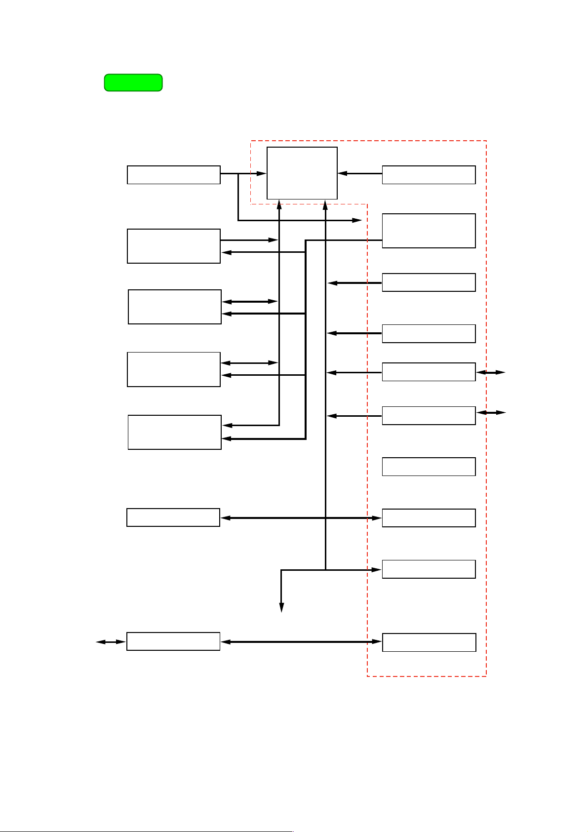
CHAPTER 3 THEORY OF OPERATION
HL-1270N
Fig. 3-6 shows the block diagram of the main PCB of the HL-1270N printer.
Reset Circuit
Program + Font ROM
4.0 Mbytes
Flash ROM
(2.0 Mbytes)
CPU Core
(MB86832)
BUS
A S I C
Oscillator (32.7MHz)
INT
Address Decoder
DRAM Control
Timer
RAM
(4.0 Mbytes)
Option RAM (SIMM)
(max. 32Mbytes)
EEPROM (4096 x 8 bits)
To Engine PCB
FIFO
CDCC Parallel I/O
USB I/O
Soft Support
EEPROM I/O
Engine Control I/O
To PC
To PC
To PC
or Hub
Network Board
PCI Bus Control
Fig. 3-6
3-6
Page 49

1.3 Main PCB
For the entire circuit diagram of the main PCB, see Appendix 11 to 17.
1.3.1 ASIC
HL-1030/1240
A Fujitsu 32bit RISC CPU, MB86833 (SPARC lite) is built in the ASIC. While the CPU is driven
with a clock frequency of 33 MHz in the user logic block, it itself runs at 66 MHz, which is
generated by multiplying the source clock by two.
The functions of the interface block communication with external devices are described below;
(1) IEEE1284
Stores the data received from the PC into DRAM as controlled by the DMA controller. It is
applicable to both normal receiving and bi-directional communication (nibble mode, byte
mode, ECP mode).
(2) USB interface (for HL-1240 only)
Stores the data received from the PC into DRAM as controlled by the DMA controller. The
transmission speed is 12Mbps.
CHAPTER 3 THEORY OF OPERATION
(3) Engine GA transfer circuit
Communicates with the engine GA by a full-duplex synchronous serial method. The
communication speed is 2Mbps.
Fig. 3-7
3-7
Page 50

CHAPTER 3 THEORY OF OPERATION
HL-1250/1270N
A Fujitsu 32bit RISC CPU, MB86832 (SPARC lite) is built in the ASIC. While the CPU is driven
with a clock frequency of 33 MHz in the user logic block, it itself runs at 66 MHz, which is
generated by multiplying the source clock by two.
The functions of the interface block communication with external devices are described below;
(1) IEEE1284
Stores the data received from the PC into DRAM as controlled by the DMA controller. It is
applicable to both normal receiving and bi-directional communication (nibble mode, byte
mode, ECP mode).
(2) USB interface
Stores the data received from the PC into DRAM as controlled by the DMA controller. The
transmission speed is 12Mbps.
(3) Engine GA transfer circuit
Communicates with the engine GA by a full-duplex synchronous serial method. The
communication speed is 2Mbps.
(4) PCI interface (for HL1270N only)
Sends and receives the data to and from the Ethernet controller ‘AM79C973AKC’. It is PCI
specification revision 2.2 compliant.
3-8
 Loading...