

Brother DCP 8040 - B/W Laser - All-in-One, MFC8840D, MFC8840DN, DCP8040, DCP8045D Service Manual
...
SERVICE MANUAL
MODEL: MFC8440/8840D/8840DN
DCP8040/8045D/8045DN
Read this manual thoroughly before maintenance work.
Keep this manual in a convenient place for quick and easy reference at all times.

© Copyright Brother Industries, Ltd. 2004
All rights reserved.
No part of this publication may be reproduced in any form or by any means without permission
in writing from the publisher.
Specifications are subject to change without notice.
Trademarks:
The brother logo is a registered trademark of Brother Industries, Ltd.
Apple, the Apple Logo, and Macintosh are trademarks, registered in the United States and
other countries, and TrueType is a trademark of Apple computer, Inc.
Microsoft and MS-DOS are registered trademarks of Microsoft Corporation.
Windows is a registered trademark of Microsoft Corporation in the U.S. and other countries.

MFC-8440/8840D/8840DN, DCP-8040/8045D/8045DN
SERVICE MANUAL
i
PREFACE
This publication is a Service Manual covering the specifications, construction, theory of
operation, and maintenance of the Brother machine. It includes information required for field
troubleshooting and repair--disassembly, reassembly, and lubrication--so that service
personnel will be able to understand machine function, to rapidly repair the machine and order
any necessary spare parts.
To perform appropriate maintenance so that the machine is always in best condition for the
customer, the service personnel must adequately understand and apply this manual.
This manual is made up of six chapters and appendices.
CHAPTER 1: GENERAL
CHAPTER 2: INSTALLATION AND BASIC OPERATION
CHAPTER 3: THEORY OF OPERATION
CHAPTER 4: DISASSEMBLY AND RE-ASSEMBLY
CHAPTER 5: PERIODIC MAINTENANCE
CHAPTER 6: TROUBLESHOOTING
CHAPTER 7: MAINTENANCE MODE
APPENDIX 1: EEPROM CUSTOMIZING CODES
APPENDIX 2: INSTALLING THE UPDATE DATA
APPENDIX 3: FIRMWARE SWITCHS (WSW)
APPENDIX 4: CIRCUIT DIAGRAMS
Information in this manual is subject to change due to improvement or redesign of the product.
All relevant information in such cases will be supplied in service information bulletins
(Technical Information).
A thorough understanding of this printer, based on information in this service manual and
service information bulletins, is required for maintaining its print quality performance and for
improving the practical ability to find the cause of problems.

TABLE OF CONTENTS
ii
TABLE OF CONTENTS
REGULATION............................................................................................ viii
SAFETY INFORMATION.............................................................................. x
CHAPTER 1 GENERAL...........................................................................1-1
1. OVERVIEW ............................................................................................................ 1-1
2. SPECIFICATIONS.................................................................................................. 1-3
2.1 General.............................................................................................................................1-3
2.2 General (Continued).........................................................................................................1-3
2.3 Print Media .......................................................................................................................1-4
2.4 Copy.................................................................................................................................1-4
2.5 Fax....................................................................................................................................1-5
2.6 Scanner............................................................................................................................1-6
2.7 Printer...............................................................................................................................1-6
2.8 Interfaces..........................................................................................................................1-7
2.9 Consumable Items ...........................................................................................................1-7
2.10 Network (LAN) Board (NC-9100h) ...................................................................................1-7
2.11 Computer Requirements ..................................................................................................1-8
2.12 Paper................................................................................................................................1-9
2.12.1 Type and size of paper........................................................................................................1-9
2.12.2 Recommended paper..........................................................................................................1-9
2.12.3 Paper capacity of the paper trays........................................................................................1-9
2.12.4 Paper specifications for each paper tray..........................................................................1-10
2.13 Printable Area.................................................................................................................1-11
2.13.1 PCL5e/EPSON/IBM emulation .......................................................................................... 1-11
2.13.2 PCL6/BR-Script3 emulation..............................................................................................1-14
2.14 Print Speeds with Various Settings ................................................................................1-15
2.15 Toner Cartridge Weight Information...............................................................................1-15
3. SERIAL NO. DESCRIPTIONS.............................................................................. 1-16
CHAPTER 2 INSTALLATION AND BASIC OPERATION.......................2-1
1. CONDITIONS REQUIRED FOR INSTALLATION................................................... 2-1
1.1 Power Supply....................................................................................................................2-1
1.2 Environment .....................................................................................................................2-1
2. UNPACKING........................................................................................................... 2-2
3. INSTALL THE MACHINE........................................................................................ 2-3
3.1 For All Users.....................................................................................................................2-3
3.1.1 Install the Automatic Document Feed (ADF) support..........................................................2-4
3.1.2 Install the drum unit assembly.............................................................................................2-5
3.1.3 Load paper into the paper tray............................................................................................2-6
3.1.4 Release the scanner lock ....................................................................................................2-7
3.2 Installing the Driver & Software ........................................................................................2-8
3.2.1 For USB Interface Cable Users (For Windows® 98/98SE/Me/2000 Professional/XP)........2-8

MFC-8440/8840D/8840DN, DCP-8040/8045D/8045DN
SERVICE MANUAL
iii
3.2.2 For Parallel Interface Cable Users
(For Windows
®
95/98/98SE/Me/2000 Professional/XP)...................................................2-13
3.2.3 For Windows NT
®
Workstation Version 4.0 Users............................................................2-18
3.2.4 For Network Interface Cable Users
(For Windows
®
95/98/98SE/Me/NT/2000 Professional/XP)..............................................2-20
3.2.5 For USB Interface Cable Users (For Mac
®
OS 8.6 to 9.2 Users)......................................2-23
3.2.6 For USB Interface Cable Users (For Mac
®
OS X 10.1/10.2.1 or greater Users)...............2-24
3.2.7 For Network Interface Cable Users (For Mac
®
OS 8.6 to 9.2 Users)................................2-25
3.2.8 For Network Interface Cable Users (For Mac
®
OS X 10.1/10.2.1 or greater Users).........2-26
CHAPTER 3 THEORY OF OPERATION................................................. 3-1
1. ELECTRONICS ...................................................................................................... 3-1
1.1 General Block Diagram ....................................................................................................3-1
1.2 Main PCB Block Diagram.................................................................................................3-2
1.3 Main PCB .........................................................................................................................3-3
1.3.1 CPU.....................................................................................................................................3-3
1.3.2 USB.....................................................................................................................................3-3
1.3.3 IEEE 1284...........................................................................................................................3-4
1.3.4 ROM....................................................................................................................................3-4
1.3.5 Flash ROM..........................................................................................................................3-5
1.3.6 SDRAM ...............................................................................................................................3-5
1.3.7 Optional RAM......................................................................................................................3-6
1.3.8 EEPROM.............................................................................................................................3-7
1.3.9 Reset circuit ........................................................................................................................3-7
1.3.10 Engine I/O ...........................................................................................................................3-7
1.3.11 Panel I/O .............................................................................................................................3-7
1.3.12 Video I/O .............................................................................................................................3-8
1.3.13 Scanner control ...................................................................................................................3-8
1.3.14 Power supply.......................................................................................................................3-9
1.4 Engine PCB....................................................................................................................3-10
1.5 Power Supply..................................................................................................................3-11
1.5.1 Low-voltage power supply.................................................................................................3-11
1.5.2 High-voltage power supply................................................................................................3-12
2. MECHANICS ........................................................................................................ 3-13
2.1 Overview of Printing Mechanism....................................................................................3-13
2.2 Scanner Mechanism.......................................................................................................3-14
2.3 Paper Transfer ...............................................................................................................3-15
2.3.1 Paper supply ..................................................................................................................... 3-15
2.3.2 Paper registration..............................................................................................................3-15
2.3.3 Paper eject........................................................................................................................3-16
2.3.4 Duplex printing ..................................................................................................................3-16
2.4 Sensors ..........................................................................................................................3-17
2.4.1 Cover sensors...................................................................................................................3-17
2.4.2 Toner sensors ...................................................................................................................3-17
2.4.3 Cassette sensor / Paper empty sensor.............................................................................3-18
2.4.4 Paper eject sensor............................................................................................................3-18
2.4.5 MP-PE sensor...................................................................................................................3-19
2.4.6 Document cover sensor....................................................................................................3-19
2.4.7 Document front sensor / Document rear sensor...............................................................3-20
2.4.8 DX-sensor PCB ASSY.......................................................................................................3-20

TABLE OF CONTENTS
iv
2.4.9 Rear cover sensor.............................................................................................................3-21
2.4.10 HP sensor.........................................................................................................................3-21
2.5 Drum Unit .......................................................................................................................3-22
2.5.1 Photosensitive drum..........................................................................................................3-22
2.5.2 Primary charger.................................................................................................................3-22
2.5.3 Transfer roller....................................................................................................................3-22
2.5.4 Cleaner..............................................................................................................................3-22
2.6 Toner Cartridge ..............................................................................................................3-22
2.7 Print Process..................................................................................................................3-22
2.7.1 Charging............................................................................................................................3-22
2.7.2 Exposure stage .................................................................................................................3-23
2.7.3 Developing........................................................................................................................3-24
2.7.4 Transfer.............................................................................................................................3-24
2.7.5 Fixing stage.......................................................................................................................3-25
CHAPTER 4 DISASSEMBLY AND RE-ASSEMBLY ..............................4-1
1. SAFETY PRECAUTIONS.......................................................................................4-1
2. DISASSEMBLY FLOW ........................................................................................... 4-2
3. DISASSEMBLY PROCEDURE............................................................................... 4-3
3.1 AC Cord............................................................................................................................4-3
3.2 Drum Unit .........................................................................................................................4-3
3.3 Paper Tray........................................................................................................................4-4
3.4 DX Feed ASSY (MFC-8840D/8840DN, DCP-8045D/8045DN only) ..............................4-14
3.5 Access Cover / Battery...................................................................................................4-17
3.6 Driver PCB Access Cover ..............................................................................................4-18
3.7 ADF Unit.........................................................................................................................4-19
3.8 Document Scanner.........................................................................................................4-28
3.9 Panel Unit.......................................................................................................................4-33
3.10 Rear Cover C (MFC-8440, DCP-8040 only)...................................................................4-36
3.11 Outer Chute (MFC-8440, DCP-8040 only) .....................................................................4-37
3.12 Rear Cover MP ASSY / Outer Chute MP ASSY
(MFC-8840D/8840DN, DCP-8045D/8045DN only)........................................................4-38
3.13 Rear Cover L/R...............................................................................................................4-39
3.14 Side Cover L/R ...............................................................................................................4-40
3.15 Joint Cover .....................................................................................................................4-41
3.16 Front Cover ASSY (MFC-8440, DCP-8040 only) ...........................................................4-45
3.17 MP Unit (MFC-8840D/8840DN, DCP-8045D/8045DN only) ..........................................4-46
3.18 Rear Cover Sensor.........................................................................................................4-51
3.19 NCU (MFC-8440/8840D/8840DN only)..........................................................................4-52
3.20 Fixing Unit.......................................................................................................................4-53
3.21 Laser Unit .......................................................................................................................4-62
3.22 Main PCB .......................................................................................................................4-64
3.23 Base Plate / LV Insulation Sheet....................................................................................4-66
3.24 DX-Sensor PCB ASSY (MFC-8840D/8840DN, DCP-8045D/8045DN only)...................4-67
3.25 Engine PCB....................................................................................................................4-68
3.26 High-voltage PS PCB ASSY...........................................................................................4-69
3.27 Low-voltage PS PCB ASSY............................................................................................4-70

MFC-8440/8840D/8840DN, DCP-8040/8045D/8045DN
SERVICE MANUAL
v
3.28 Paper Feeder..................................................................................................................4-71
3.29 Frame L / Drive Unit .......................................................................................................7-78
3.30 Reversing Release Solenoid (MFC-8840D/8840DN, DCP-8045D/8045DN only)..........4-82
3.31 Thermistor ASSY............................................................................................................4-83
3.32 Fan Motor 60 Unit LV / Fan Motor 60 Unit......................................................................4-83
3.33 Frame R..........................................................................................................................4-84
4. PACKING.............................................................................................................. 4-86
5. GUIDELINES FOR LEAD FREE SOLDER............................................................ 4-87
6. SCREW TORQUE LIST........................................................................................ 4-90
7. LUBRICATION...................................................................................................... 4-92
8. HARNESS ROUTING........................................................................................... 4-97
CHAPTER 5 PERIODIC MAINTENANCE...............................................5-1
1. CONSUMABLE PARTS.......................................................................................... 5-1
1.1 Drum Unit .........................................................................................................................5-1
1.2 Toner Cartridge ................................................................................................................5-3
2. PERIODICAL REPLACEMENT PARTS .................................................................. 5-7
2.1 Fixing Unit.........................................................................................................................5-8
2.2 Paper Feeding Kit ...........................................................................................................5-16
3. PERIODICAL CLEANING..................................................................................... 5-20
3.1 Cleaning the Machine Exterior .......................................................................................5-20
3.2 Cleaning the Scanner.....................................................................................................5-20
3.3 Cleaning the Printer........................................................................................................5-21
3.4 Cleaning the Drum Unit ..................................................................................................5-22
3.5 Cleaning the Scanner Window.......................................................................................5-22
3.6 Cleaning the Electrical Terminals...................................................................................5-23
4. MTBF / MTTR....................................................................................................... 5-24
CHAPTER 6 TROUBLESHOOTING ....................................................... 6-1
1. INTRODUCTION .................................................................................................... 6-1
1.1 Initial Check......................................................................................................................6-1
1.2 Warnings for Maintenance Work......................................................................................6-2
1.3 Identify the Problem..........................................................................................................6-3
2. ERROR MESSAGE................................................................................................ 6-4
2.1 Error Message on the LCD...............................................................................................6-4
2.2 Error Codes Shown in the “MACHINE ERROR X
X” message........................................6-7
3. PAPER PROBLEMS............................................................................................. 6-11
3.1 Paper Loading Problems................................................................................................6-11
3.2 Original Jams..................................................................................................................6-12
3.2.1 Original is jammed in the top of the ADF unit....................................................................6-12
3.2.2 Original is jammed inside the ADF unit.............................................................................6-12
3.3 Paper Jams ....................................................................................................................6-13
3.3.1 Clearing jammed paper.....................................................................................................6-13
3.3.2 Paper is jammed in the Duplex Tray (For MFC-8840D/8840DN, DCP-8045D/8045DN)..6-16
3.3.3 Causes & countermeasures..............................................................................................6-17

TABLE OF CONTENTS
vi
3.4 Paper Feeding Problems................................................................................................6-18
4. SOFTWARE SETTING PROBLEMS .................................................................... 6-20
5. MALFUNCTIONS.................................................................................................. 6-23
6. TROUBLESHOOTING OF THE CONTROL PANEL............................................. 6-28
7. TROUBLESHOOTING OF FAX FUNCTIONS ...................................................... 6-30
8. IMAGE DEFECTS................................................................................................. 6-34
8.1 Image Defect Examples.................................................................................................6-34
8.2 Diameter of Rollers.........................................................................................................6-34
8.3 Troubleshooting Image Defect.......................................................................................6-35
8.4 Location of Grounding Contacts.....................................................................................6-53
8.4.1 Drum unit...........................................................................................................................6-53
8.4.2 Machine body & Paper tray ..............................................................................................6-53
9. INCORRECT PRINTOUT ..................................................................................... 6-54
10. NETWORK PROBLEM......................................................................................... 6-56
10.1 Installation Problem........................................................................................................6-56
10.2 Intermittent Problem .......................................................................................................6-57
10.3 TCP/IP Troubleshooting.................................................................................................6-58
10.4 UNIX Troubleshooting....................................................................................................6-58
10.5 Windows
®
NT/LAN Server (TCP/IP) Troubleshooting....................................................6-59
10.6 Windows
®
95/98/Me Peer to Peer Print (LPR) Troubleshooting ....................................6-59
10.7 Windows
®
95/98/Me Peer to Peer (HP JetAdmin Compatible Method) Troubleshooting........6-59
10.8 Windows
®
95/98/Me/NT 4.0/2000 Peer to Peer Print (NetBIOS) Troubleshooting........6-60
10.9 Brother Internet Print (TCP/IP) Troubleshooting ............................................................6-60
10.10 Windows
®
95/98/Me/2000/XP IPP Troubleshooting.......................................................6-60
10.11 Novell Netware Troubleshooting ....................................................................................6-61
10.12 AppleTalk Troubleshooting.............................................................................................6-62
10.13 DLC/LLC Troubleshooting..............................................................................................6-62
10.14 Web Browser Troubleshooting (TCP/IP)........................................................................6-62
10.15 Internet Fax Troubleshooting..........................................................................................6-63
CHAPTER 7 MAINTENANCE MODE...................................................... 7-1
1. ENTRY INTO THE MAINTENANCE MODE............................................................ 7-1
2. LIST OF MAINTENANCE–MODE FUNCTIONS..................................................... 7-2
3. DETAILED DESCRIPTION OF MAINTENANCE-MODE FUNCTIONS................... 7-4
3.1 EEPROM Parameter Initialization (Maintenance mode 01/91) ........................................7-4
3.2 Printout of Scanning Compensation Data (Maintenance mode 05).................................7-5
3.3 Placement of CCD Unit in Position for Transportation (Maintenance mode 06)..............7-7
3.4 ADF Performance Test (Maintenance mode 08) .............................................................7-7
3.5 Test Pattern 1 (Maintenance mode 09)............................................................................7-8
3.6 Firmware Switch Setting and Printout ..............................................................................7-9
3.6.1 Firmware switch setting (Maintenance mode 10)................................................................7-9
3.6.2 Printout of firmware switch data (Maintenance mode 11).................................................7-11
3.7 Operation Check of LCD (Maintenance mode 12).........................................................7-12
3.8 Operational Check of Control Panel PCB (Maintenance mode 13) ...............................7-13
3.9 Sensor Operational Check (Maintenance mode 32)......................................................7-14
3.10 Received Data Transfer Function (Maintenance mode 53)............................................7-16

MFC-8440/8840D/8840DN, DCP-8040/8045D/8045DN
SERVICE MANUAL
vii
3.11 Fine Adjustment of Scan Start/End Positions (Maintenance mode 54)..........................7-18
3.12 CCD Scanner Area Setting (Maintenance mode 55) .....................................................7-20
3.13 EEPROM Customizing (Maintenance mode 74)............................................................7-21
3.14 Printing out of Machine Log Information (Maintenance mode 77)..................................7-22
3.15 Display of the Equipment’s Log Information (Maintenance mode 80)............................7-24
3.16 Machine Error Code Indication (Maintenance mode 82)................................................7-26
3.17 Output of Transmission Log to the Telephone Line (Maintenance mode 87) ................7-26
3.18 Cancellation of the Memory Security Mode (Not applicable to the Japanese version) .7-27
APPENDIX 1 EEPROM CUSTOMIZING CODES ...................................A-1
APPENDIX 2 INSTALLING THE UPDATE DATA....................................A-3
1. INSTALLING THE UPDATE DATA TO THE MACHINE..........................................A-3
1.1 Connecting the Machine to Your PC ................................................................................A-3
1.2 Setting up the Machine and Your PC ...............................................................................A-3
1.3 Installing the Update Data onto the Flash ROM of the Machine ......................................A-4
2. SETTING ID CODES TO MACHINES.....................................................................A-5
2.1 Connecting the Machine to Your PC ................................................................................A-5
2.2 Setting Up the Machine and Your PC...............................................................................A-5
2.3 Running the Setup Utility..................................................................................................A-6
APPENDIX 3 FIRMWARE SWITCHS (WSW) .........................................A-7
APPENDIX 4 CIRCUIT DIAGRAMS
4.1 Main PCB Circuit Diagram (1/7).....................................................................................A-50
4.2 Main PCB Circuit Diagram (2/7).....................................................................................A-51
4.3 Main PCB Circuit Diagram (3/7).....................................................................................A-52
4.4 Main PCB Circuit Diagram (4/7).....................................................................................A-53
4.5 Main PCB Circuit Diagram (5/7).....................................................................................A-54
4.6 Main PCB Circuit Diagram (6/7).....................................................................................A-55
4.7 Main PCB Circuit Diagram (7/7).....................................................................................A-56
4.8 Driver PCB Circuit Diagram ...........................................................................................A-57
4.9 Engine PCB Circuit Diagram (1/2)..................................................................................A-58
4.10 Engine PCB Circuit Diagram (2/2)..................................................................................A-59
4.11 NCU PCB Circuit Diagram (U.S.A.)................................................................................A-60
4.12 NCU PCB Circuit Diagram (Europe) ..............................................................................A-61
4.13 NCU PCB Circuit Diagram (Asia) ...................................................................................A-62
4.14 NCU PCB Circuit Diagram (Oceania).............................................................................A-63
4.15 Control Panel PCB Circuit Diagram................................................................................A-64
4.16 Low-voltage Power Supply PCB Circuit Diagram (200V) ...............................................A-65
4.17 Low-voltage Power Supply PCB Circuit Diagram (100V) ...............................................A-66
4.18 High-voltage Power Supply PCB Circuit Diagram (200V) ..............................................A-67
4.19 High-voltage Power Supply PCB Circuit Diagram (100V) ..............................................A-68

REGULATION
viii
REGULATION
LASER SAFETY (110 - 120V MODEL ONLY)
This printer is certified as a Class I laser product under the US Department of Health and
Human Services (DHHS) Radiation Performance Standard according to the Radiation
Control for Health and Safety Act of 1968. This means that the printer does not produce
hazardous laser radiation.
Since radiation emitted inside the printer is completely confined within the protective
housing and external covers. the laser beam cannot escape form the machine during any
phase of user operation.
FDA REGULATIONS (110 - 120V MODEL ONLY)
The US Food and Drug Administration (FDA) has implemented regulations for laser
products manufactured on and after August 2, 1976. Compliance is mandatory for
products marketed in the United States. One of the following labels on the back of the
printer indicates compliance with the FDA regulations and must be attached to laser
products marketed in the United States.
The label for Japanese manufactured products
MANUFACTURED: K
BROTHER INDUSTRIES, LTD.
15-1, Naeshiro-cho, Mizuho-ku, Nagoya 467-8561,
Japan.
This product complies with FDA radiation performance
standards, 21 CFR Subchapter J.
The label for Chinese manufactured products
MANUFACTURED: C
BROTHER Corporation (Asia) Ltd.
Shenzen Buji Nan Ling Factory
Gold Garden Ind., Nan Ling Village, Buji, Rong Gang,
Shenzen, CHINA
This product complies with FDA radiation performance
standards, 21 CFR Subchapter J.
Caution
Use of controls, adjustments or performance of procedures other than those specified in
this manual may result in hazardous radiation exposure.

MFC-8440/8840D/8840DN, DCP-8040/8045D/8045DN
SERVICE MANUAL
ix
IEC 825 (220-240V MODEL ONLY)
This printer is a Class I laser product as defined in IEC 825 specifications. The label
shown below is attached in countries where required.
CLASS 1LASERP RODUCT
APPAREIL Å LASER DE CLASSE 1
LASER KLASSE 1 PRODUKT
This printer has a laser diode which emits invisible laser radiation in the Laser Unit. The
Laser Unit should not be opened without disconnecting the two connectors connected with
the AC power supply and laser unit. Since the variable resistor in the laser unit is adjusted
in accordance with the standards, never touch it.
Caution
Use of controls, adjustments or performance of procedures other than those specified in
this manual may result in hazardous radiation exposure.
For Finland and Sweden
LUOKAN 1 LASERLAITE
KLASS 1 LASER APPARAT
Varoitus! Laitteen käyttäminen muulla kuin tässä käyttöohjeessa mainitulla tavalla saattaa
altistaa käyttäjän turvallisuusluokan 1 ylittävälle näkymättömälle lasersäteilylle.
Varning – Om apparaten används på annat sätt än i denna Bruksanvisning specificerats,
kan användaren utsättas för osynlig laserstrålning, som överskrider gränsen för laserklass
1.
SAFETY INFORMATION
x
SAFETY INFORMATION
CAUTION FOR LASER PRODUCT (WARNHINWEIS FUR LASER DRUCKER)
CAUTION: When the machine during servicing is operated with the cover open, the
regulations of VBG 93 and the performance instructions for VBG 93 are
valid.
CAUTION: In case of any trouble with the laser unit, replace the laser unit itself. To
prevent direct exposure to the laser beam, do not try to open the enclosure
of the laser unit.
ACHTUNG: Im Falle von Störungen der Lasereinheit muß diese ersetzt werden. Das
Gehäuse der Lasereinheit darf nicht geöffnet werden, da sonst
Laserstrahlen austreten können.
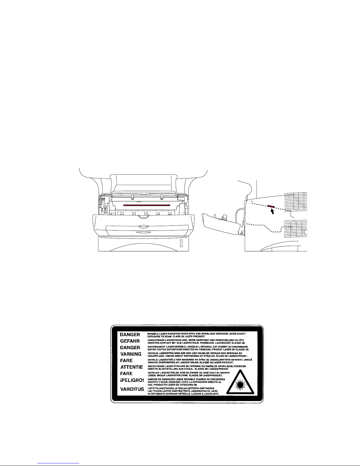
<Location of the laser beam window>
ADDITIONAL INFORMATION
When servicing the optical system of the printer, be careful not to place a screwdriver or
other reflective object in the path of the laser beam. Be sure to take off any personal
accessories such as watches and rings before working on the printer. A reflected beam,
though invisible, can permanently damage the eyes.
Since the beam is invisible, the following caution label is attached on the laser unit.
MFC-8440/8840D/8840DN, DCP-8040/8045D/8045DN
SERVICE MANUAL
xi
DEFINITIONS OF WARNINGS, CAUTIONS AND NOTES
The following conventions are used in this service manual:
WARNING
Indicates warnings that must be observed to prevent possible personal injury.
!
CAUTION:
Indicates cautions that must be observed to service the printer properly or prevent damage
to the printer.
NOTE:
Indicates notes and useful tips to remember when servicing the printer.
**Listed below are the various kinds of “WARNING” messages included in this manual.
WARNING
Always turn off the power switch and unplug the power cord from the power outlet
before accessing any parts inside the printer.
WARNING
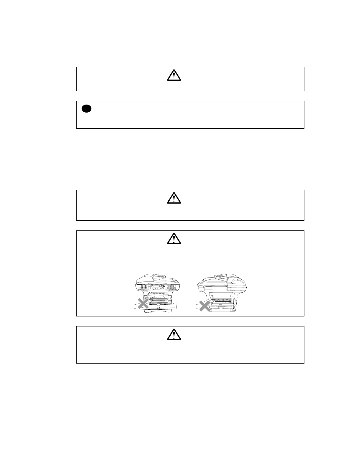
Some parts inside the printer are extremely hot immediately after the printer is used.
When opening the front cover or back cover to access any parts inside the printer,
never touch the shaded parts shown in the following figures.
WARNING
If you analyze malfunctions with the power plug inserted into the power outlet,
special caution should be exercised even if the power switch is OFF because it is a
single pole switch.
MFC-8440/8840D/8840DN, DCP-8040/8045D/8045DN
SERVICE MANUAL
1-1
CHAPTER 1 GENERAL
1. OVERVIEW
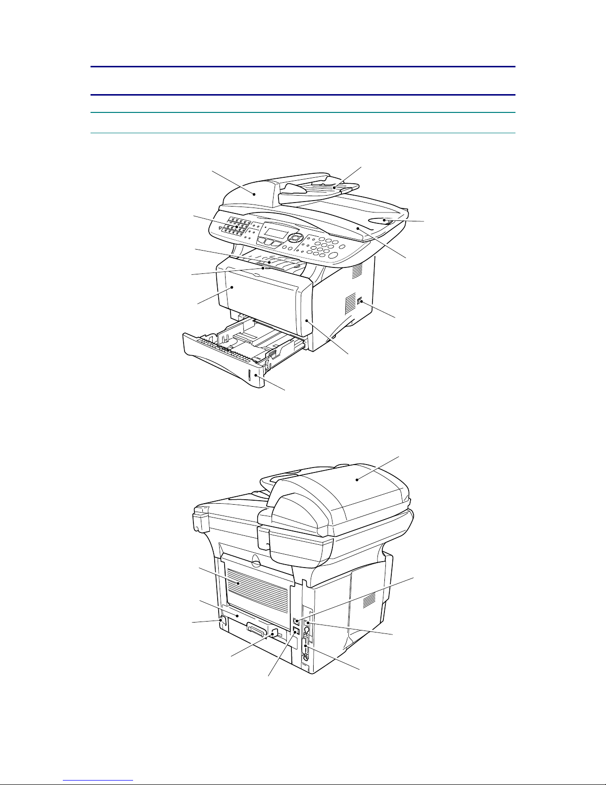
<Front View>
Fig. 1-1
<Back View>
Fig. 1-2
A
DF document support extension
Document cover
Power switch
Front cover
A
utomatic docum ent feeder (ADF)
Control panel
Face-down output
tray support flap
Front cover release button
Manual feed tray
(MFC-8440, DCP-8040)
Multi-purpose tray (MP tray)
(MFC-8840D/8840DN,
DCP-8045D/8045DN)
A
DF cover
Telephone line jack
USB interface connect or
Parallel interface connector
External telephone line jack
Paper adjustment lever
for duplex printing
(MFC-8840D/8840DN,
DCP-8045D/8045DN)
Duplex tray
(MFC-8840D/8840DN,
DCP-8045D/8045DN)
A
C power connector
Face-up output tray
(Back output tray)
A
DF document output support f l ap
Paper tray (Tray #1)
CHAPTER 1 GENERAL
1-2
<Inside View (Document Cover Open)>
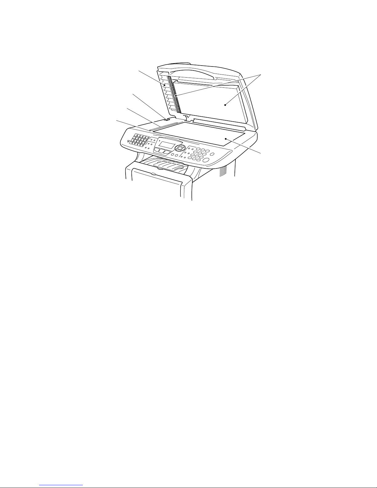
Fig. 1-3
White film
Scanner glass
Document guidelines
Glass strip
Scanner lock lever
Document cover

MFC-8440/8840D/8840DN, DCP-8040/8045D/8045DN
SERVICE MANUAL
1-3
2. SPECIFICATIONS
2.1 General
Memory Capacity
32 MB
Optional Memory
1 DIMM slot; Memory expandable up to 160 MB
Automatic Document
Up to 50 pages
Paper Tray
250 Sheets (20 lb)
Multi-Purpose Tray
50 Sheets (20 lb) (MFC-8840D/8840DN, DCP-8045D/8045DN
only)
Manual Feed Tray
Single sheet (20 lb) (MFC-8440, DCP-8040 only)
Printer Type
Laser
Print Method
Electrophotography by semiconductor laser beam scanning
LCD
(Liquid Crystal
Display)
22 characters x 5 lines
Warm-up
Max. 18 seconds at 73.4°F (23°C)
Power Source
120V AC 50/60Hz (U.S.A., CANADA Version only)
Power Consumption
Average Operating (Copying): 450 W or less (25°C)
Peak: 1090 W or less
Sleep: with Network 16 W or less
with out Network 14 W or less
Standby: 85 W or less (25°C)
Dimensions
20.7 x 17.3 x 18.3 (in.)
532 x 444 x 469 (mm)
Weight
Without Drum/Toner Unit:
MFC-8440, DCP-8040: 36.6 lb/16.6 kg
MFC-8840D/8840DN, DCP-8045D/8045DN: 39.9 lb/18.1 kg
Noise
Operating: 53 dB A or less
Standby: 30 dB A or less
2.2 General (Continued)
Temperature
Operating: 50 - 90.5°F (10 - 32.5°C)
Storage: 32 - 104°F (0 - 40°C)
Humidity
Storage: 20 to 80% (without condensation)
Operating: 10 to 90% (without condensation)

CHAPTER 1 GENERAL
1-4
2.3 Print Media
Paper Input
<Paper Tray>
• Paper type:
Plain paper, recycled paper and transparencies, envelopes
(Manual Feed/Multi-purpose Tray)
• Paper size:
A4, Letter, Legal, B5 (ISO), B5 (JIS), Executive, A5, A6,
B6 (ISO)
Weight: 16 - 28 lb (60 - 105 g/m
2
) (Paper Tray)
For more details, see Paper specifications for each paper
tray on page 1-10.
• Maximum paper tray capacity:
Approx. 250 sheets of 20 lb (80 g/m
2
) plain paper
• Maximum multi-purpose tray capacity:
Approx. 50 sheets of 20 lb (80 g/m
2
) plain paper
(MFC-8840D/8840DN, DCP-8045D/8045DN only)
< Manual Feed Tray/Multi-Purpose Tray >
• Paper size:
Width: 20 lb 2.75 - 8.66" (69.8 - 220.0 mm)
Height: 4.60 - 16.00" (116.0 - 406.4 mm)
Weight: 16 - 43 lb (60 - 161 g/m
2
)
Paper Output
Up to 150 sheets of plain paper (Face up print delivery to the
output paper support)
2.4 Copy
Color/Monochrome
Monochrome
Copy Speed
Up to 21 copies/minute (Letter paper)
Up to 20 copies/minute (A4 paper)
Multiple Copies
Stacks or Sorts up to 99 pages
Enlarge/Reduce
25% to 400% (in increments of 1%)
Resolution
600 dpi

MFC-8440/8840D/8840DN, DCP-8040/8045D/8045DN
SERVICE MANUAL
1-5
2.5 Fax
Compatibility
ITU-T Group 3
Coding System
MH/MR/MMR/JBIG
Modem Speed
33600 bps
Automatic Fallback
Original Size
ADF Width: 5.8" to 8.5" (148 mm to 216 mm)
ADF Height: 5.8" to 14.0" (148 mm to 356 mm)
Scanner Width: Max. 8.48" (212 mm)
Scanner Height: Max. 14.0" (356 mm)
Scanning Width
8.2 inches (208 mm)
Printing Width
8.2 inches (208 mm)
Gray Scale
64 levels
Polling Types
Standard, Sequential
Contrast Control
Automatic/Light/Dark (manual setting)
Resolution
• Horizontal 203 dot/inch (8 dot/mm)
• Vertical
• Standard 98 line/inch (3.85 line/mm)
• Fine, Photo 196 line/inch (7.7 line/mm)
• Superfine 392 line/inch (15.4 line/mm)
One-Touch Dial
40 (20 x 2)
Speed-Dial
300 stations
Automatic Redial
One time
Auto Answer
0, 1, 2, 3 or 4 rings
Communication
Source
Public switched telephone network.
Memory Transmission
Up to 600 pages (Brother #1 Chart)
Out of Paper
Reception
Up to 600 pages (Brother #1 Chart)

CHAPTER 1 GENERAL
1-6
2.6 Scanner
Color/Monochrome
Color/Monochrome
TWAIN Compliant
Yes (Windows
®
95/98/98SE/Me/2000 Professional and Windows
NT
®
Workstation Version 4.0)
WIA Compliant
Yes (Windows
®
XP)
Resolution
Up to 9,600 x 9,600 dpi (interpolated)*
Up to 600 x 2,400 dpi (optical)
* Maximum 1200 x 1200 dpi scanning with Windows
®
XP
(resolution up to 9600 x 9600 dpi can be selected by using the
Brother scanner utility)
Document Size
ADF Width: 5.8" to 8.5" (148 mm to 216 mm)
ADF Height: 5.8" to 14.0" (148 mm to 356 mm)
Scanner Glass Width: Max. 8.5" (216 mm)
Scanner Glass Height: Max. 14.0" (356 mm)
Scanning Width
8.35 inches (212 mm)
Gray Scale
256 levels
Scanning Speed
Color: 1.80 msec/line (Up to 300 x 300 dpi)
: 3.60 msec/line (400 x 400 dpi or higher)
Monochrome: 0.84 msec/line (ADF)
: 1.01 msec/line (Scanner Glass)
NOTE:
• Scanning directly to a networked PC is available with Windows
®
98/98SE/Me/2000
Professional and XP.
• OS X scanning is supported in OS X 10.2.1 or greater.
2.7 Printer
Emulation
PCL6 (Brother Printing System for Windows
®
emulation mode of
HP LaserJet) and BR-Script (PostScript
®
) Level 3
Printer Driver
Windows
®
95/98/98SE/Me/2000 Professional/XP and Windows
NT
®
Workstation Version 4.0 driver supporting Brother Native
Compression mode and bi-directional capability
Apple
®
Macintosh® Quick Draw® Driver and PostScript (PPD) for
OS 8.6-9.2/OS X 10.1/10.2.1 or Greater
Resolution
HQ1200 (Max. 2400 x 600 dots/inch)
Print Quality
Normal printing mode
Economy printing mode (saves toner usage)
Print Speed
Up to 21 pages/minute letter size
Up to 20 pages/minute A4 size
(when loading paper from paper tray)
Duplex Printing
Up to 9 images/minute: (MFC-8840D/8840DN,
DCP-8045D/8045DN only)
First Print
Up to 12 seconds (using letter size paper in paper tray)

MFC-8440/8840D/8840DN, DCP-8040/8045D/8045DN
SERVICE MANUAL
1-7
2.8 Interfaces
Interface
Recommended Cable
Parallel
A bi-directional shielded parallel cable that is IEEE 1284 compliant
and not longer than 6 feet (2 m).
USB
A Hi-Speed USB 2.0 cable that is not longer than 6 feet (2 m).
NOTE:
• Please make sure that you use a Hi-Speed USB 2.0 certified cable if your computer uses a
Hi-Speed USB 2.0 interface.
• Even if your computer has a USB 1.1 interface you can connect the MFC.
• To meet FCC/CISPR emission requirements for the MFC, you must attach the included
filter core and cable tie to the parallel interface cable.
2.9 Consumable Items
Toner Cartridge Life
Expectancy
TN-540/TN-3030: Standard Toner Cartridge - Up to 3,500* pages
TN-570/TN-3060: High Yield Toner Cartridge - Up to 6,700* pages
*(when printing letter size or A4 paper at 5% print coverage)
NOTE:
Toner life expectancy will vary depending upon the type of
average print job.
Drum Unit Life
Expectancy
Up to 20,000 pages/drum unit (DR-3000)
NOTE:
There are many factors that determine the actual drum life, such
as temperature, humidity, type of paper, toner you use and
number of pages per print job.
2.10 Network (LAN) Board (NC-9100h)
MFC-8440/8840D
(Option)
MFC-8840DN
(Standard)
DCP-8040/8045D
(Option)
When you add the optional Network (LAN) Board (NC-9100h), you
can connect your MFC into the network to use the Internet FAX,
Network Scanner, Network Printer and Network Management
software operations for small workgroups.
NOTE:
SMTP/POP3 E-mail Services are required for Internet Fax.
Support for:
Windows
®
95/98/Me/NT® 4.0/2000/XP Novell NetWare 3.X,
4.X, 5.X Mac OS 8.6 - 9.2, X 10.0-10.2.1 or Greater Ethernet
10/100 BASE-TX Auto Negotiation TCP/IP, IPX/SPX,
AppleTalk, DLC/LLC RARP, BOOTP, DHCP, APIPA,
NetBIOS, WINS LPR/LPD, Port9100, SMTP/POP3
SMB(NetBIOS/ IP), IPP, SSDP, Rendezvous, FTP MIBII as
well as Brother private MIB TELNET, SNMP, HTTP, TFTP
Included Utilities:
BRAdmin Professional and Web Based
Management
NOTE:
• Scanning directly to a networked PC is not supported in
Windows
®
95, NT® and Mac OS.
• BRAdmin Professional is not supported in Mac OS.
CHAPTER 1 GENERAL
1-8
2.11 Computer Requirements
Minimum System Requirements
Available Hard Disk
Space
Computer Platform &
Operating
System Version
Processor
Minimum
Speed
Minimum
RAM
Recommended
RAM
Driver
Application
Software
*1
95, 98,
98SE
Pentium
75MHz
24 MB 32 MB
Me
Pentium
150MHz
NT®
Workstation
4.0
Pentium
75MHz
32 MB 64 MB
2000
Professional
Pentium
133MHz
100 MB
Windows®
Operating
System
XP
Pentium
233MHz
64 MB 128 MB
80 MB
180 MB
OS 8.6 - 9.2
(Printing,
Scanning
and PC-FAX
Send Only)
32 MB 64 MB
Apple®
Macintosh
®
Operating
System
Mac OS X
10.1/10.2.1
or greater
(Printing,
Scanning
*2
PC-FAX
Send and
Remote
Setup Only)
All base
models meet
minimum
Requirements
128 MB 160 MB
50 MB 200 MB
NOTE:
USB is not supported under Windows
®
95 or Windows NT® WS 4.0.
All registered trademarks referenced herein are the property of their respective companies.
For the latest drivers, go to the Brother Solutions Center at http://solutions.brother.com/
*1
Application software is different for Windows® and Macintosh®.
*2
Scanning is supported in 10.2.1 or greater.
MFC-8440/8840D/8840DN, DCP-8040/8045D/8045DN
SERVICE MANUAL
1-9
2.12 Paper
2.12.1 Type and size of paper
The machine loads paper from the installed paper tray, manual feed tray, multi-purpose tray or
optional lower tray.
Tray type Model name
Paper tray (Tray #1) MFC-8440/8840D/8840DN, DCP-8040/8045D/8045DN
Manual feed tray MFC-8440, DCP-8040
Multi-purpose tray (MP tray) MFC-8840D/8840DN, DCP-8045D/8045DN
Optional lower tray (Tray #2) Option for MFC-8440/8840D/8840DN,
DCP-8040/8045D/8045DN
2.12.2 Recommended paper
Plain Paper: Plain Paper: Xerox 4200DP 20 lb
Hammermill Laser Paper 24 lb
Transparency: 3M CG 3300
Labels: Avery laser label # 5160
2.12.3 Paper capacity of the paper trays
Paper size Number of sheets
Multi-purpose tray (MP tray)
(MFC-8840D/8840DN,
DCP-8045D/8045DN)
Width: 69.8 to 220 mm
(2.75 to 8.66 in.)
Height: 116 to 406.4 mm
(4.57 to 16.0 in.)
50 sheets
(80 g/m
2
or 20 lb)
Manual feed tray
(MFC-8440, DCP-8040)
Width: 69.8 to 220 mm
(2.75 to 8.66 in.)
Height: 116 to 406.4 mm
(4.57 to 16.0 in.)
Single sheet
Paper tray (Tray #1) A4, Letter, Legal, B5 (ISO),
B5 (JIS), Executive, A5, A6,
B6 (ISO)
250 sheets
(80 g/m
2
or 20 lb)
Optional lower tray (Tray #2) A4, Letter, Legal, B5 (ISO),
B5 (JIS), Executive, A5, B6
(ISO)
250 sheets
(80 g/m
2
or 20 lb)
Duplex printing A4, Letter, Legal —

CHAPTER 1 GENERAL
1-10
2.12.4 Paper specifications for each paper tray
Model
MFC-8440
DCP-8040
MFC-8840D/8840DN
DCP-8045D/8045DN
Multi-purpose tray N/A
Plain paper, Bond paper,
Recycled paper,
Envelope
*1
, Labels, and
Transparency
*2
Manual feed tray
Plain paper, Bond paper,
Recycled paper,
Envelope, Labels, and
Transparency
N/A
Paper tray Plain paper, Recycled paper, and Transparency*2
Paper types
Optional lower tray Plain paper, Recycled paper, and Transparency
*2
Multi-purpose tray
N/A
60 to 161 g/m2
(16 to 43 lb)
Manual feed tray 60 to 161 g/m2
(16 to 43 lb)
N/A
Paper tray 60 to 105 g/m2 (16 to 28 lb)
Paper weights
Optional lower tray 60 to 105 g/m
2
(16 to 28 lb)
Multi- purpose tray
N/A
Width: 69.8 to 220 mm
(2.75 to 8.66 in.)
Height: 116 to 406.4 mm
(4.57 to 16.0 in.)
Manual feed tray Width: 69.8 to 220 mm
(2.75 to 8.66 in.)
Height: 116 to 406.4 mm
(4.57 to 16.0 in.)
N/A
Paper tray A4, Letter, Legal, B5 (ISO), B5 (JIS), Executive, A5,
A6, B6 (ISO)
Paper sizes
Optional lower Tray A4, Letter, Legal, B5 (ISO), B5 (JIS), Executive, A5,
B6 (ISO)
*1 Up to 3 envelopes
*2 Up to 10 sheets
NOTE:
Remove each transparency immediately.
MFC-8440/8840D/8840DN, DCP-8040/8045D/8045DN
SERVICE MANUAL
1-11
!
CAUTION:
When you are choosing print media, be sure to follow the information given below to prevent
any paper jams, print quality problems or machine damage;
• It is recommended to use long-grained paper for the best print quality. If short-grained
paper is being used, it might be the cause of paper jams.
• Use neutral paper. Do not use acid paper to avoid any damage to the drum unit.
• Avoid using coated paper such as vinyl coated paper.
• Avoid using preprinted or highly textured paper.
• It is recommended to use labels or transparencies which are designed for use in laser
printers.
• Avoid feeding labels with the carrier sheet exposed, or the machine will be damaged.
• Before loading paper with holes such as organizer sheets, be sure to fan the stack well.
• Do not use organizer sheets that are stuck together. The glue that is used might caused
damaged to the machine.
• When printing on the back of pre-printed paper, if the paper is curled, be sure to straighten
the paper as much as possible.
• Different types of paper should not be loaded at the same time in the paper tray to avoid
any paper jams or misfeeds.
2.13 Printable Area
2.13.1 PCL5e/EPSON/IBM emulation
The figure below shows the printable area each emulation guarantees when printing on Portrait
and Landscape.
Portrait
A
B
C
D
E
F
G
F
G
E
G
G
Physical page
Printable area
Logical page
B Physical page length
D
Maximum logical page length
F
Distance from edge of physical page to
edge of logical page

CHAPTER 1 GENERAL
1-12
The table below shows the printable areas when printing on Portrait for each paper size.
Size A B C D E F G
Letter
215.9 mm
8.5”
(2,550 dots)
279.4 mm
11.0”
(3,300 dots)
203.2 mm
8.0”
(2,400 dots)
279.4 mm
11.0”
(3,300 dots)
6.35 mm
0.25”
(75 dots)
0 mm
4.2 mm
0.16”
(50 dots)
Legal
215.9 mm
8.5”
(2,550 dots)
355.6 mm
14.0”
(4,200 dots)
203.2 mm
8.0”
(2,400 dots)
355.6 mm
14.0”
(4,200 dots)
á
0 mm
4.2 mm
0.16”
(50 dots)
Folio
215.9 mm
8.5”
(2,550 dots)
330.2mm
13.0”
(3,900 dots)
203.2 mm
8.0”
(2,400 dots)
330.2mm
13.0”
(3,900 dots)
á
0 mm
4.2 mm
0.16”
(50 dots)
Executive
184.15 mm
7.25”
(2,175 dots)
266.7 mm
10.5”
(3,150 dots)
175.7 mm
6.92”
(2,025 dots)
266.7 mm
10.5”
(3,150 dots)
6.35 mm
0.25”
(75 dots)
0 mm
4.2 mm
0.16”
(50 dots)
A 4
210.0 mm
8.27”
(2,480 dots)
297.0 mm
11.69”
(3,507 dots)
198.0 mm
7.79”
(2,338 dots)
297.0 mm
11.69”
(3,507 dots)
6.01 mm
0.24”
(71 dots)
0 mm
4.2 mm
0.16”
(50 dots)
A 5
148.5 mm
5.85”
(1,754 dots)
210.0 mm
8.27”
(2,480 dots)
136.5 mm
5.37”
(1,612 dots)
210.0 mm
8.27”
(2,480 dots)
á
0 mm
4.2 mm
0.16”
(50 dots)
A 6
105.0 mm
4.13”
(1,240 dots)
148.5 mm
5.85”
(1,754 dots)
93.0 mm
3.66”
(1,098 dots)
148.5 mm
5.85”
(1,754 dots)
á
0 mm
4.2 mm
0.16”
(50 dots)
B 5 (JIS)
182.0 mm
7.1”
(2,130 dots)
257.0 mm
10.11”
(3,033 dots)
170.0 mm
6.69”
(2,007 dots)
257.0 mm
10.11”
(3,033 dots)
á
0 mm
4.2 mm
0.16”
(50 dots)
B 5 (ISO)
176.0 mm
6.93”
(2,078 dots)
250.0 mm
9.84”
(2,952 dots)
164.0 mm
6.46”
(1,936 dots)
250.0 mm
9.84”
(2,952 dots)
á
0 mm
4.2 mm
0.16”
(50 dots)
B 6 (ISO)
125.0 mm
4.92”
(1,476 dots)
176.0 mm
6.93”
(2,078 dots)
164.0 mm
4.44”
(1,334 dots)
176.0 mm
6.93”
(2.078 dots)
á
0 mm
4.2 mm
0.16”
(50 dots)
COM10
104.78 mm
4.125”
(1,237 dots)
241.3 mm
9.5”
(2,850 dots)
92.11 mm
3.63”
(1,087 dots)
241.3 mm
9.5”
(2,850 dots)
6.35 mm
0.25”
(75 dots)
0 mm
4.2 mm
0.16”
(50 dots)
MONARCH
98.43 mm
3.875”
(1,162 dots)
190.5 mm
7.5”
(2,250 dots)
85.7 mm
3.37”
(1,012 dots)
190.5 mm
7.5”
(2,250 dots)
á
0 mm
4.2 mm
0.16”
(50 dots)
C 5
162.0 mm
6.38”
(1,913 dots)
229.0 mm
9.01”
(2,704 dots)
150.0 mm
5.9”
(1,771 dots)
229.0 mm
9.01”
(2,704 dots)
6.01 mm
0.24”
(71 dots)
0 mm
4.2 mm
0.16”
(50 dots)
DL
110.0 mm
4.33”
(1,299 dots)
220.0 mm
8.66”
(2,598 dots)
98.0 mm
3.86”
(1,157 dots)
220.0 mm
8.66”
(2,598 dots)
á
0 mm
4.2 mm
0.16”
(50 dots)
NOTE:
• The paper sizes indicated here should confirm to the nominal dimensions specified by JIS
except B5 (ISO).
• The dot size is based on 300 dpi resolution.

MFC-8440/8840D/8840DN, DCP-8040/8045D/8045DN
SERVICE MANUAL
1-13
Landscape
A
B
C
D
E
F
G
F
G
E
G
G
Physical page
Printable area
Logical page
B Physical page length
D Maximum logical page length
F Distance from edge of physical
page to edge of logical page

CHAPTER 1 GENERAL
1-14
The table below shows the printable areas when printing on Landscape for each paper size.
Size A B C D E F G
Letter
279.4 mm
11.0”
(3,300 dots)
215.9 mm
8.5”
(2,550 dots)
269.3 mm
10.6”
(3,180 dots)
215.9 mm
8.5”
(2,550 dots)
5.0 mm
0.2”
(60 dots)
0 mm
4.2 mm
0.16”
(50 dots)
Legal
355.6 mm
14.0”
(4,200 dots)
215.9 mm
8.5”
(2,550 dots)
345.5 mm
13.6”
(4,080 dots)
215.9 mm
8.5”
(2,550 dots)
á
0 mm
4.2 mm
0.16”
(50 dots)
Folio
330.2mm
13.0”
(3,900 dots)
215.9 mm
8.5”
(2,550 dots)
320.0mm
12.6”
(3,780 dots)
215.9 mm
8.5”
(2,550 dots)
á
0 mm
4.2 mm
0.16”
(50 dots)
Executive
266.7 mm
10.5”
(3,150 dots)
184.15 mm
7.25”
(2,175 dots)
256.6 mm
10.1”
(3,030 dots)
184.15 mm
7.25”
(2,175 dots)
5.0 mm
0.2”
(60 dots)
0 mm
4.2 mm
0.16”
(50 dots)
A 4
297.0 mm
11.69”
(3,507 dots)
210.0 mm
8.27”
(2,480 dots)
287.0 mm
11.2”
(3,389 dots)
210.0 mm
8.27”
(2,480 dots)
4.8 mm
0.19”
(59 dots)
0 mm
4.2 mm
0.16”
(50 dots)
A 5
210.0 mm
8.27”
(2,480 dots)
148.5 mm
5.85”
(1,754 dots)
200.0mm
7.87”
(2,362 dots)
148.5 mm
5.85”
(1,754 dots)
á
0 mm
4.2 mm
0.16”
(50 dots)
A 6
148.5 mm
5.85”
(1,754 dots)
105.0 mm
4.13”
(1,240 dots)
138.5 mm
5.45”
(1,636 dots)
105.0 mm
4.13”
(1,240 dots)
á
0 mm
4.2 mm
0.16”
(50 dots)
B 5 (JIS)
257.0 mm
10.11”
(3,033 dots)
182.0 mm
7.1”
(2,130 dots)
247.0 mm
9.72”
(2,916 dots)
182.0 mm
7.1”
(2,130 dots)
á
0 mm
4.2 mm
0.16”
(50 dots)
B 5 (ISO)
250.0 mm
9.84”
(2,952 dots)
176.0 mm
6.93”
(2,078 dots)
240.0 mm
9.44”
(2,834 dots)
176.0 mm
6.93”
(2,078 dots)
á
0 mm
4.2 mm
0.16”
(50 dots)
B 6 (ISO)
176.0 mm
6.93”
(2,078 dots)
125.0 mm
4.92”
(1,476 dots)
166.4 mm
6.55”
(1,960 dots)
125.0 mm
4.92”
(1,476 dots)
á
0 mm
4.2 mm
0.16”
(50 dots)
COM10
241.3 mm
9.5”
(2,850 dots)
104.78 mm
4.125”
(1,237 dots)
231.1 mm
9.1”
(2,730 dots)
104.78 mm
4.125”
(1,237 dots)
5.0 mm
0.2”
(60 dots)
0 mm
4.2 mm
0.16”
(50 dots)
MONARCH
190.5 mm
7.5”
(2,250 dots)
98.43 mm
3.875”
(1,162 dots)
180.4 mm
7.1”
(2,130 dots)
98.43 mm
3.875”
(1,162 dots)
á
0 mm
4.2 mm
0.16”
(50 dots)
C 5
229 mm
9.01”
(2,704 dots)
162 mm
6.38”
(1,913 dots)
219.0 mm
8.62”
(2,586 dots)
162 mm
6.38”
(1,913 dots)
4.8 mm
0.19”
(59 dots)
0 mm
4.2 mm
0.16”
(50 dots)
DL
220 mm
8.66”
(2,598 dots)
110 mm
4.33”
(1,299 dots)
210.0 mm
8.26”
(2,480 dots)
110 mm
4.33”
(1,299 dots)
á
0 mm
4.2 mm
0.16”
(50 dots)
NOTE:
• The paper sizes indicated here should confirm to the nominal dimensions specified by JIS
except B5 (ISO).
• The dot size is based on 300 dpi resolution.
2.13.2 PCL6/BR-Script3 emulation
You can not print within 4.2 mm (50dots in 300 dpi mode) on all four sides of the paper.
MFC-8440/8840D/8840DN, DCP-8040/8045D/8045DN
SERVICE MANUAL
1-15
2.14 Print Speeds with Various Settings
Print speed of the machine is up to 16/17 ppm when loading A4 or Letter size paper from the
paper tray in the plain paper mode.
Actual print speed varies depending on the media type or paper size as shown in the tables
below;
<A4 / Letter size>
Media type setting All models
Transparencies Up to 21/20 ppm
Thin Paper Up to 21/20 ppm
Plain paper, Env.Thin Up to 21/20 ppm
Thick Paper, Envelopes Up to 21/20 ppm
Thicker/Bond Paper, Env.Thick 4 ppm *
<Smaller size than A4 or Letter>
Media type setting All models
Transparency Up to 21/20 ppm
Thin Paper Up to 21/20 ppm
Plain paper, Env.Thin 8 ppm after 5 min. have passed.
Thick Paper, Envelopes 8 ppm after 30 sec. have passed.
Thicker/Bond Paper, Env.Thick 4 ppm *
*The print speed may vary according to conditions, such as paper size and paper tray.
NOTE:
• When a smaller size paper than A4 or Letter is printed, the temperature on both edges of
the fixing unit is much higher than the temperature on the center of the unit where the paper
is fed depending on the setting or model. Therefore, the print speed is slowed in order to
decrease the temperature on the edges after the specified time, it is maximum print speed
when you first start printing.
• Max. speed is 16/17 ppm or more. It varies depending on the paper size.
2.15 Toner Cartridge Weight Information
Toner Cartridge Weight (approx weight)
TN3060/TN570 TN3030/TN540
Brand new Toner Cartridge Weight 827.5g 772.5g
Toner Weight at Brand New Toner Cartridge 197.5±2.5g 142.5±2.5g
Toner Cartridge Weight at Toner Near Empty 693.5-698.5g 693.5-698.5g
Remain Toner Weight at Toner Near Empty 80-85g 80-85g
Toner Cartridge Weight at Toner Empty 678.5-683.5g 678.5-683.5g
Remain Toner Weight at Toner Empty 60-70g 60-70g
You can print 500 to 600 pages with 10g toner.
*Without yellow protector
*Toner cartridge weight may vary within 2 to 3g depending on the cartridge weight.

CHAPTER 1 GENERAL
1-16
3. SERIAL NO. DESCRIPTIONS
The descriptions below show how to understand the meanings of the numbers printed on the
labels or bag of the machine and machine parts:
< ID for production month >
A: January B: February C: March D: April
E: May F: June G: July H: August
J: September K: October L: November M: December
< ID for year >
3: 2003 4: 2004
< ID for factory >
9: Kariya Plant A: Mie Brother C: BIUK
J: Buji Nan Ling Factory
(1) Machine: Printed on the label attached on the rear of the main body
<Example>
U 6 0 6 6 1 D 4 J 1 1 1 0 1 1
(2) Process unit: Imprinted on the aluminum bag
(Drum unit with toner cartridge)
3 A 1 1 J A
(3) Drum unit: Printed on the bar code label attached inside the drum unit
A 3 9 5 1 0 0 1 0 4 A
YEAR
MONTH
DATE
FACTORY ID NO.
YEAR
MONTH
SERIAL NO.
<MODEL NO.>
MONTH
YEAR
FACTORY ID NO.
SEQUENTIAL NO.
< SERIAL NO. >
FACTORY ID NO.
PRODUCTION
LINE NO.
TONER VOLUME
PRODUCT LINE NO.

MFC-8440/8840D/8840DN, DCP-8040/8045D/8045DN
SERVICE MANUAL
1-17
(4) Toner cartridge: Imprinted on the aluminum bag
3 A 3 0 J
Printed on the bar code label attached on the toner cartridge
M 3 9 A 0 0 0 1 9 9 A
(5) Laser unit: On the laser unit
2 8 0 0 1
YEAR
MONTH
DATE
FACTORY ID NO.
YEAR
MONTH
SERIAL NO.
PRODUCTION LOT NO.
LASER UNIT NO. 8: LJ7516001 Laser Uni t ZL2
FACTORY ID NO.
FACTORY ID NO.
CARTRIDGE
PRODUCTION INFO.
1: Kariya Plant
2: Buji Nan Ling Factory
TONER VOLUME
PRODUCT LINE NO.
 Loading...