

Page 1

FACSIMILE EQUIPMENT
SERVICE MANUAL
MODELS: MFC620CN
MFC420CN/410CN
MFC210C
FAX2440C
DCP310CN/110C
Confidential
Page 2

© Copyright B r other 2004-2005
All rights reserved.
No part of this publi c ati on may be reproduced i n any
form or by any means without perm ission in wri ting
from the publi sher.
Specifications are subject to change wit hout notice.
Confidential
Page 3

Preface
This Service Manual is intended for use by service personnel and details the specifications,
const ruction, t heory of operat ion, and ma intenance for the Brother machines noted on the front cover.
It includes information required for troubleshooting and service--disassembly, reassembly, and
lubrication--so that service personnel will be able to understand equipment function, repair the
equipment in a timely manner a nd order s pare parts as neces sary.
To per for m app rop ria te maint enance s o tha t the mac hine is alwa ys in the bes t poss ible condit ion for
the cus tomer, service personnel must adequa tely unders tand and apply this manual .
How this manual is organized
This ma nual is ma de u p of nine chap ters and ap pendices.
CHAPTER 1 PARTS NAMES AND FUNCTIONS
Conta ins ext erna l views and na mes of components and desc ribes their fu nctions . Infor mation abou t
the keys on the control p anel is included to help you check op erat ion or make adjustments.
CHAPTER 2 SPECIFICATIONS
List s the sp ecif ic ations of each model, which enab les you to make a c omparison of different models.
CHAPTER 3 THEORY OF OPERATION
Gives a n overview of the s canning a nd print ing mechanisms a s well as the sensor s, a ctua tors, and
control electronics. It aids in understanding the basic principles of operation as well as locating
defects f or troubl es hooting.
CHAPTER 4 TRANSFER OF DATA LEFT IN THE M ACHINE TO BE SE NT FOR REP AIR
Descr ib es how to t r a nsf er da ta left in t he machine to b e sent f or r epa ir . T he s ervic e per sonnel s hould
inst ru ct end u s er s t o f oll ow t he t r ans fer pr o cedu re giv en in thi s ch a p t er if t he mac hi ne a t t he u s er s i t e
cannot print received dat a due t o the print ing mechanism defective. End us ers ca n tr ansfer r eceived
data to another machine to prevent data loss.
CHAPTER 5 DISASSEMBLY/REASSEMBLY AND LUBRICATION
Deta ils pr ocedur es for disa ss embling a nd rea ssembling t he machine t ogether wit h rela ted notes . The
disassembly order flow provided enables you to see at a glance the quickest way to get to
component(s ) involved.
At the star t of a disa ssembly job, you check a disa ssembly order flow that guides you through a
shortcut to the ob ject components .
This chapter also covers screw tightening torques and lubrication points to which the specified
lubricants shou ld be app lied du ring reassembly job s.
CHAPTER 6 ADJUSTMENTS AND UPDATING OF SETTINGS RE QUIRED AFTER P ARTS
REPLACEMENT
Deta ils a dju st ments a nd up da t ing of s ett ings , which a r e r equir ed if t he head/ ca r r i a ge unit, ma in PC B
and some other part s have been replac ed.
CHAPTER 7 CLEANING
Provides cleaning pr ocedures not covered by the User's Manu al. Before starting any repair work,
clean t he mac hine as it ma y solve the pr oblem concerned.
i Confidential
Page 4

CHAPTER 8 MAINTENANCE MODE
Describes the maintenance mode which is exclusively designed for the purpose of checks, settings
and adjustments using the keys on the control panel.
In the maintenance mode, you can update memory (EEPROM: electrically erasable programmable
read-only memory) contents for optimizing the drive conditions of the head/carriage unit, paper
feed roller or paper ejection roller (if they have been replaced) or for setting the CIS scanner area,
for example. You can also customize the EEPROM according to the shipment destination of the
machine concerned. In addition, you can perform operational checks of the LCD, control panel
PCB or sensors, perform a print test, display the log information or error codes, and modify
firmware switches (WSW).
CHAPTER 9 ERROR INDICATION AND TROUBLESHOOTING
Details error messages and codes that the incorporated self-diagnostic functions display if any error
or malfunction occurs. If any error message appears, refer to this chapter to find which components
should be checked or replaced.
The latter half of this chapter provides sample problems that could occur in the main sections of the
machine and related troubleshooting procedures. This will help service personnel pinpoint and
repair defective components.
Appendix 1 Serial Numbering System
Shows the location of serial number labels put on some parts and lists the coding information
pertaining to the serial numbers.
Appendix 2 Firmware Installation
Provides instructions on how to update firmware stored in the flash ROM on the main PCB or load
firmware to a new main PCB from the host PC.
No hardware replacement is required for updating.
Appendix 3 Customizing Codes According to Shipping Destination
Provides instructions on how to set up the customizing codes for the various preferences
exclusively designed for each destination (e.g. language). Those codes are stored in the memory
(EEPROM) mounted on the main PCB. If the main PCB is replaced, therefore, you need to set up
the proper customizing code with the machine in the maintenance mode.
Customizing codes customize firmware for individual models, enabling the common firmware to
be used for various models. They come with the firmware data provided by Brother Industries.
Appendix 4 Firmware Switches (WSW)
Describes the functions of the firmware switches, which can be divided into two groups: one is for
customizing preferences designed for the shipping destination (as described in Appendix 3) and the
other is for modifying preferences that match the machine to the environmental conditions. Use the
latter group if the machine malfunctions due to mismatching.
Appendix 5 Wiring Diagram
Provides the wiring diagram that helps you understand the connections between PCBs.
Appendix 6 Circuit Diagrams
Provides the circuit diagrams of the MJ PCB and power supply PCB.
ii Confidential
Page 5

Appendix 7 Viewing the Event Log File
When insta lling the p rint er dr iver, t he insta ller logs events tha t occur dur ing the inst alla tion pr ocess
in the event log file. T his ap pendix views a sample of t he event log file. Selecting S ta rt | P rogr am |
Brot her | MF L-Pro Suite model name | Inst allation Diagnostics rea ds out the event log file.
This manual describes the models and their versions destined for major countries. The specifications and
functions are subject to change depending upon each destination.
iii Confidential
Page 6
SAFETY PRECAUTIONS
To use the machine safely
Please refer to these instructions for later reference and before attempting any maintenance.
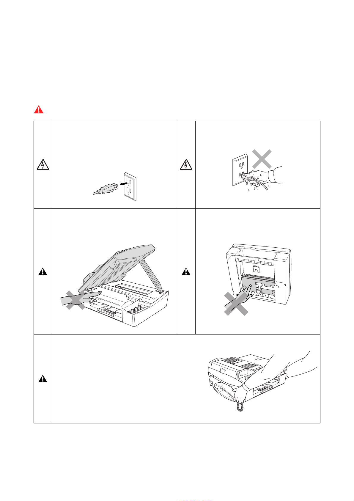
WARNING
There are high voltage electrodes inside the
machine. Before you clean the machine,
make sure you have unplugged t he
telephone line c or d fir st and then the power
cord from the AC power outlet .
To prevent injuries, be careful not to put your
hands on the edge of the machine under the
scanner cover.
Do not handle the plug with wet hands. Doing
this might cause an el ectr ic al shock.
To prevent injuries, be careful not to touch
the area shaded in the illustration.
When moving the machine you must lift it
from the base, by placing a hand at each side
of the unit as shown in the illustr ation. Do
NOT carry the machine by holding the
scanner cover.
iv Confidential
Page 7
WARNING
n Use caution when in stalling or modifyin g telephone line s. Neve r touch tele phone wi res o r termin als th at are
not insulated unless the telephone line has been disconnected at the wall jack. Never install telephone
wiring during a lightning storm. Never install a telephone wall jack in a wet location.
n This prod uct m ust be in stalled ne ar an A C powe r outlet that is e asily acc e ssible . In case of eme rgencie s, yo u
must disconnect the power cord from the AC power outlet in order to shut off power completely.
n To reduce the r isk of s hock or fire, use onl y a No. 26 AWG or larger telecommunication line cord.
Caution
n Lightning and power surges can damage this product! We recommend that you use a quality surge
protection device on the AC power line and on the telephone line, or unplug the cords during a lightning
storm.
n When lifting up the machine, hold it from the base. Holding the scanning cover (scanner unit) leaves the
machine body inclined, disengaging the scanner cover from the machine body or letting the machine body
fall.
IMPORTANT SAFETY INSTRUCTIONS
When using your telephone equipment, basic saf ety pr ec autions should always be followed to
reduce the risk of fi r e, electric shock and injury to persons, i ncluding the following:
1. Do not use this product near water, for example, near a bath tub, wash bowl, kitchen sink or
washing machine, in a wet basem ent or near a swimming pool.
2. Avoid using this product during an electrical storm . T her e m ay be a rem ote risk of elec tric shock
from lightning.
3. Do not use this product t o report a gas leak in t he vi ci nity of the leak.
4. Use only the power cord provi ded with the MFC.
SAVE THESE INSTRUCTIONS
v Confidential
Page 8
Choosing a location
Place your MFC on a flat, stable surface that is free of vibration and shocks, such as a desk. Put the MFC near
a telephone wall jack and a standard, grounded AC power outlet. Choose a location where the temperature
remains between 50°F and 95°F (10°C and 35°C).
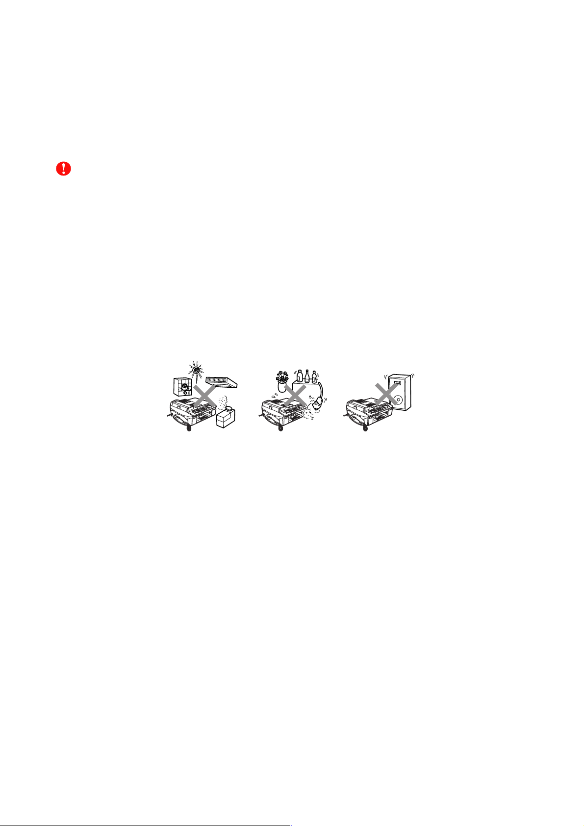
Caution
n Avoid placing your MFC in a high-traffic area.
n Avoid placing your MFC on the carpet.
n Do not place near heaters, air conditioners, water, chemicals, or refrigerators.
n Do not expose the MFC to direct sunlight, excessive heat, moisture, or dust.
n Do not connect your MFC to electrical outlets controlled by wall switches or automatic timers.
n Disruption of power can wipe out information in the MFC’s memory.
n Do not connect your MFC to electrical outlets on the same circuit as large appliances or other equipment
that might disrupt the power supply.
n Avoid interference sources, such as speakers or the base units of cordless phones.
vi Confidential
Page 9

CHAPTER
PARTS NAMES & FUNCTIONS
Confidential
Page 10

CHAPTER 1 PARTS NAMES & FUNCTIONS
This chapter contains external views and names of components and describes their functions.
Information about the keys on the control panel is included to help you check operation or make
adjustments.
CONTENTS
1.1 OUTLINE .........................................................................................................................1-1
1.2 CONTROL PANEL .......................................................................................................... 1-3
1.3 COMPONENTS ............................................................................................................... 1-9
Confidential
Page 11
1.1 OUTLINE
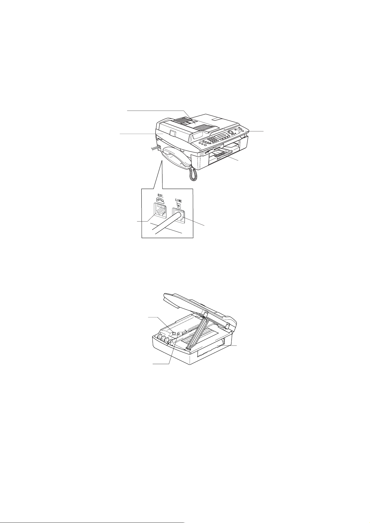
Front view
(6) ADF & document
cover ASSY
(5) Scanner cover
(Scanner unit)
(4) External telephone line jack
Rear view
(1) Control panel
(2) Paper tray
(3) Telephone line jack
(8) LAN cable connector*
(7) USB interface connector
(9) Jam clear cover
*Provided on the MFC620CN/420CN/410CN and DCP310CN
1-1 Confidential
Page 12

No. Name Description
(1) Control panel
(2) Paper tray
Use the keys to operate the machine. The liquid crystal display
(LCD) shows the machine operation status.
Load paper here. Paper will be fed into the machine, sheet by
sheet.
(3) Telephone line jack Plug in the modular plug on the telephone line here.
(4) External telephone line jack Plug in the modular plug on the external telephone line here.
(5) Scanner cover (Scanner unit) Open to load ink cartridges or remove jammed paper.
ADF: Load documents (originals) here. Documents will be fed
ADF* & document cover ASSY
into the machine, page by page.
(6)
(*MFC620CN/420CN and FAX2440C)
Document cover: Open to place the document (original) on the
scanner glass.
(7) USB interface connector Connect the USB cable here.
LAN cable connector
(8)
(MFC620CN/420CN/410CN and
DCP310CN)
Connect the LAN cable here.
(9) Jam clear cover Open to remove paper jammed inside the machine.
1-2 Confidential
Page 13
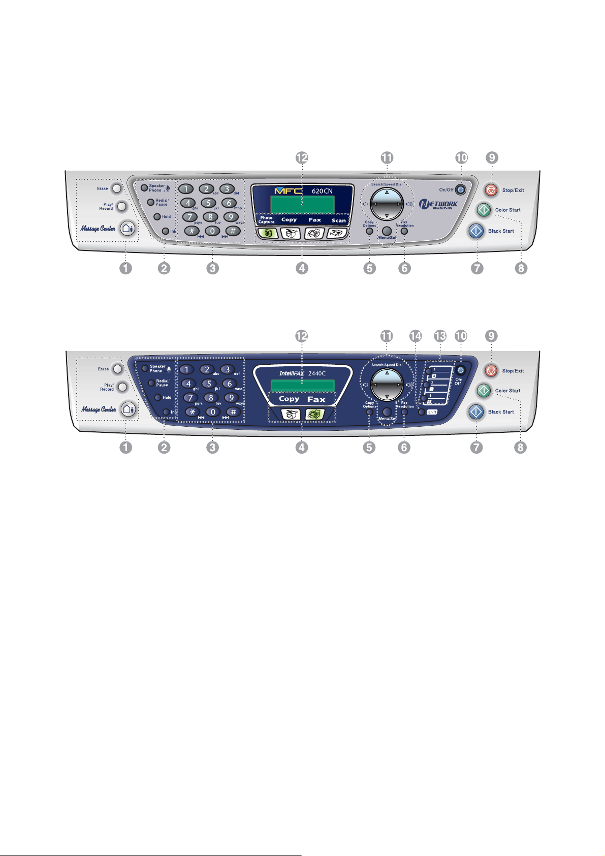
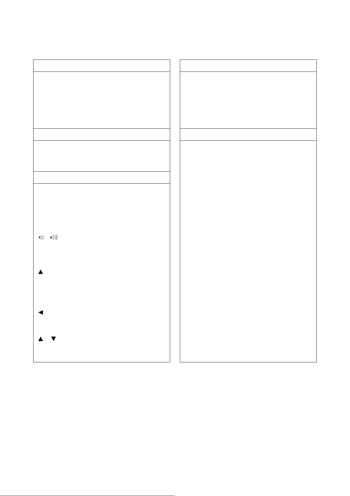
1.2 CONTROL PANEL
n MFC620CN
n FAX2440C
1-3 Confidential
Page 14
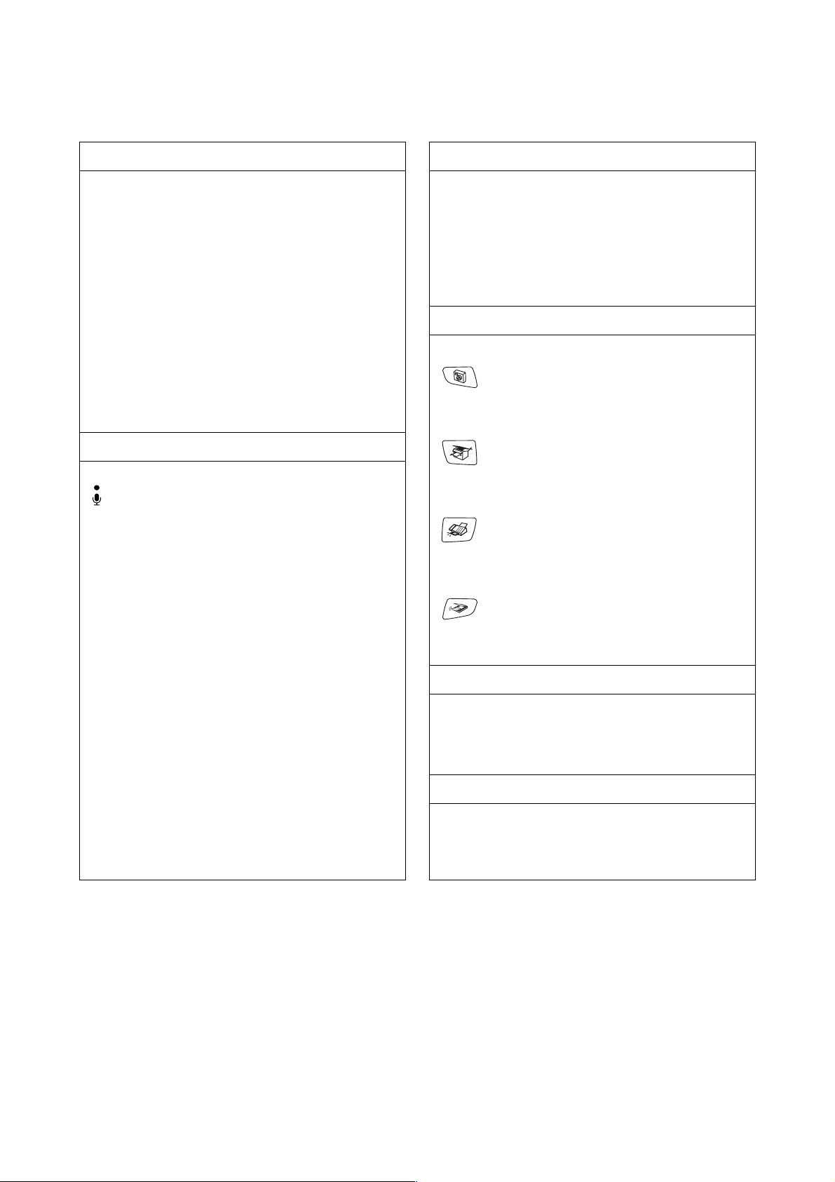
1. Message Center keys 3. Dial Pad
MC On/Off
Lets you activate the Message Center and will blink
if you have new messages.
Play/Record
Lets you listen to voice messages stored in memory.
Also, lets you record telephone calls.
Erase
Lets you delete voice messages, all fax messages or
all messages.
2. Telephone keys
Microphone
Picks up your voice when you speak to another party
using Speaker Phone.
Speaker Phone
Lets you speak to another party without lifting the
handset.
Use these keys to dial telephone and fax numbers
and as a keyboard for entering information into the
machine.
The # key lets you temporarily switch the dialing
mode during a telephone call from Pulse to Tone.
4. Mode keys
PhotoCapture (MFC620CN only)
Lets you access the PhotoCapture Center™ mode.
Copy
Lets you access Copy mode.
Fax
Lets you access Fax mode.
Scan (MFC620CN only)
Lets you access Scan mode.
Redial/Pause
Redials the last number you called. It also inserts a
pause in auto dial numbers.
Hold
Lets you place telephone calls on hold.
Ink
Lets you clean the print heads, check the print
quality, and check the available ink volume.
5. Copy Options
You can quickly and easily select temporary settings
for copying.
6. Fax Resolution
Adjusts the resolution when you send a fax.
1-4 Confidential
Page 15
7. Black Start
Lets you start sending faxes or making copies in
black and white.
Also for MFC620CN, lets you start a scanning
operation. (Color or mono, depending on the
scanning setting on your PC)
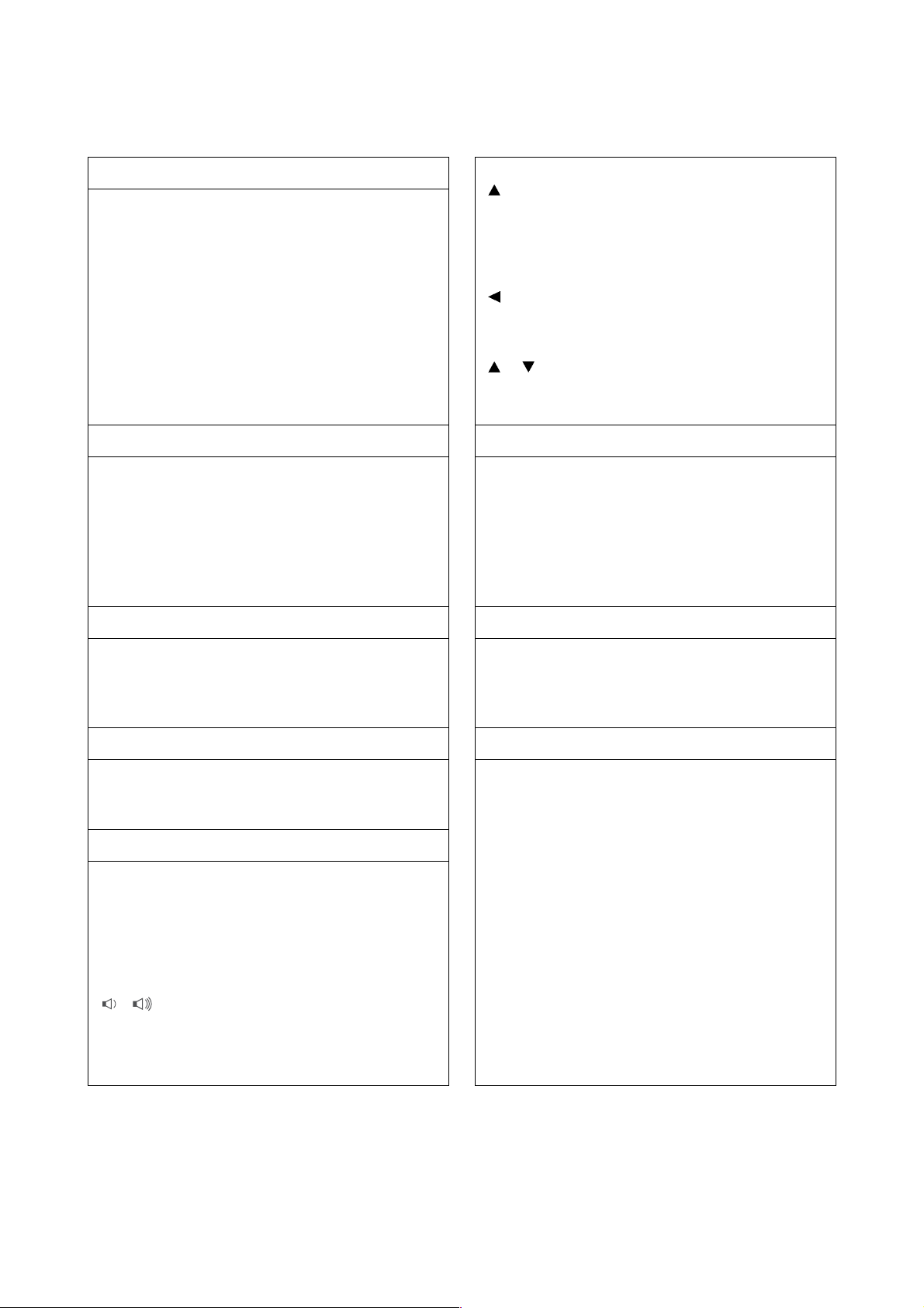
8. Color Start 12. Liquid Crystal Display (LCD)
Search/Speed Dial
Lets you look up numbers that are stored in the
dialing memory. It also lets you dial stored numbers
by pressing # and a two-digit number.
Press to scroll backward to a menu selection.
or
Press to scroll through the menus and options.
Lets you start sending faxes or making copies in full
color.
Also for MFC620CN, lets you start a scanning
operation. (Color or mono, depending on the
scanning setting on your PC)
Displays messages on the screen to help you set up
and use your machine.
The LCD examples are for models with a two-line
display. There may be slight differences between the
examples and models that have a one-line display.
9. Stop/Exit 13. One-Touch keys (FAX2440C only)
Stops an operation or exits from the menu. These keys give you instant access to previously
stored Quick-Dial numbers.
10. On/Off 14. Shift (FAX2440C only)
You can turn the machine on or off.
Lets you access memory locations 4 to 6 in the OneTouch keys.
11. Navigation keys
Menu/Set
The same key is used for Menu and Set operations.
Lets you access the Menu to program and store your
settings in the machine.
When using the speaker or during ringing in fax
mode, you can press these keys to adjust the volume.
1-5 Confidential
Page 16

n MFC210C
1-6 Confidential
Page 17
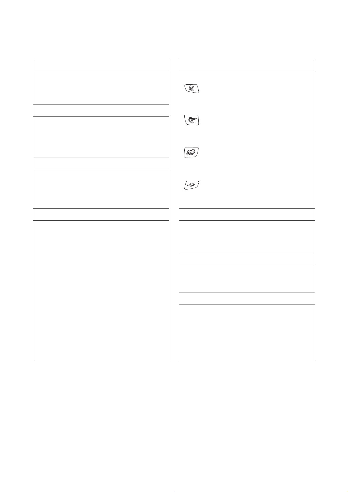
1. Redial/Pause 5. Mode keys
Redials the last number you called. It also inserts a
pause in auto dial numbers.
2. Hook
Press before dialing if you want to make sure a
machine will answer, and then press Black Start or
Color Start.
3. Ink
Lets you clean the print heads, check the print
quality, and check the available ink volume.
4. Dial Pad 6. Copy Options
Use these keys to dial telephone or fax numbers and
as a keyboard for entering information into the MFC.
The # key lets you temporarily switch the dialing
mode during a telephone call from Pulse to Tone.
PhotoCapture
Lets you access the PhotoCapture Center™ mode.
Copy
Lets you access Copy mode.
Fax
Lets you access Fax mode.
Scan
Lets you access Scan mode.
You can quickly and easily select temporary settings
for copying.
7. Fax Resolution
Sets the resolution when you send a fax.
8. Black Start
Lets you start sending faxes or making copies in
black and white.
Also lets you start a scanning operation. (Color or
mono, depending on the scanning setting on your
PC)
1-7 Confidential
Page 18
9. Color Start 12. Liquid Crystal Display (LCD)
Lets you start sending faxes or making copies in full
color.
Also lets you start a scanning operation. (Color or
mono, depending on the scanning setting on your
PC)
10. Stop/Exit 13. On/Off
Stops an operation or exits from the menu.
11. Navigation keys
Menu/Set
The same key is used for Menu and Set operations.
Lets you access the Menu to program and store your
settings in the MFC.
When using the speaker or during ringing in fax
mode, you can press these keys to adjust the volume.
Displays messages on the screen to help you set up
and use your MFC. The LCD examples in this guide
are for models with a two-line display. There may be
slight differences between the examples provided
and models with a one-line display.
You can turn the MFC on or off.
Search/Speed Dial
Lets you look up numbers that are stored in the
dialing memory. It also lets you dial stored numbers
by pressing # and a two-digit number.
Press to scroll backward to a menu selection.
or
Press to scroll through the menus and options.
1-8 Confidential
Page 19
1.3 COMPONENTS
The machine consists of the following major components:
Scanner cover
(Scanner unit)
Scanner cover
damper
Scanner cover
stopper
Upper cover
Ink absorber box
Document cover***
ADF & document
cover ASSY**
Control panel
ASSY
Head/carriage unit
Maintenance unit
Engine unit
Ink refill
ASSY
Lower cover
Hook switch
PCB*
Handset
mount*
Handset*
MJ/PS shield
box
Power supply
PCB
* MFC620CN U.S.A./Canadian models and FAX2440C
** MFC620CN/420CN and FAX2440C
*** MFC410CN/210C and DCP310CN/110C
1-9 Confidential
Main PCB
ASSY
Paper tray
MJ PCB
Page 20

CHAPTER
SPECIFICATIONS
Confidential
Page 21

CHAPTER 2 SPECIFICATIONS
This chapter lists the specifications of each model, which enables you to make a comparison of
different models.
CONTENTS
2.1 GENERAL........................................................................................................................2-1
2.1.1 General Specifications.........................................................................................2-1
2.1.2 Paper Specifications............................................................................................2-3
2.1.3 Printable Area......................................................................................................2-6
2.2 SPECIFICATIONS LIST .................................................................................................. 2-7
Confidential
Page 22

2.1 GENERAL
2.1.1 General Specifications
Memory Capacity
MFC620CN:
Automatic Document Feeder (ADF) Up to 10 sheets
MFC620CN/420CN and FAX2440C only)
(
Paper Tray 100 sheets (20 lb.)
Printer Type Ink Jet
Print Method Piezo with 74 nozzles for each of three colors + a pair of 74 nozzles
Liquid Crystal Display (LCD)
MFC620CN:
Operating Environment 50 to 95°F (10 to 35°C)
Best Print Quality 68 to 91°F (20 to 33°C)
Power Source 100 to 120 VAC, 50/60 Hz (U.S.A./Canada)
Power Consumption
MFC620CN U.S.A./Canadian models:
MFC620CN European/Asian models: Minimum: under 4.0 Wh
16 MB
for black
16 characters x 2 lines
230 VAC, 50/60 Hz (Europe/Asia)
Minimum: under 3.5 Wh
Standby: 9.5 Wh or less (25°C)
Peak: 27 Wh or less
Standby: 9.5 Wh or less (25°C)
Peak: 26 Wh or less
2-1 Confidential
Page 23
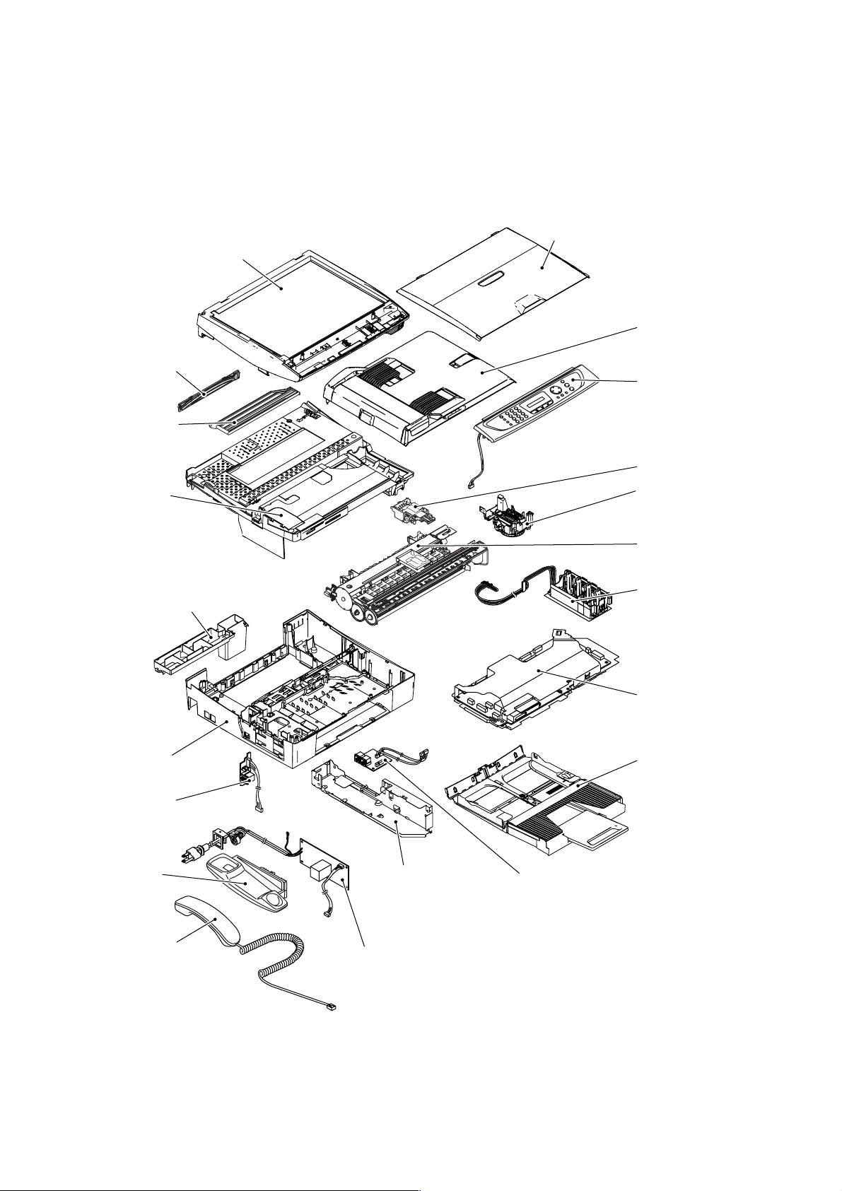
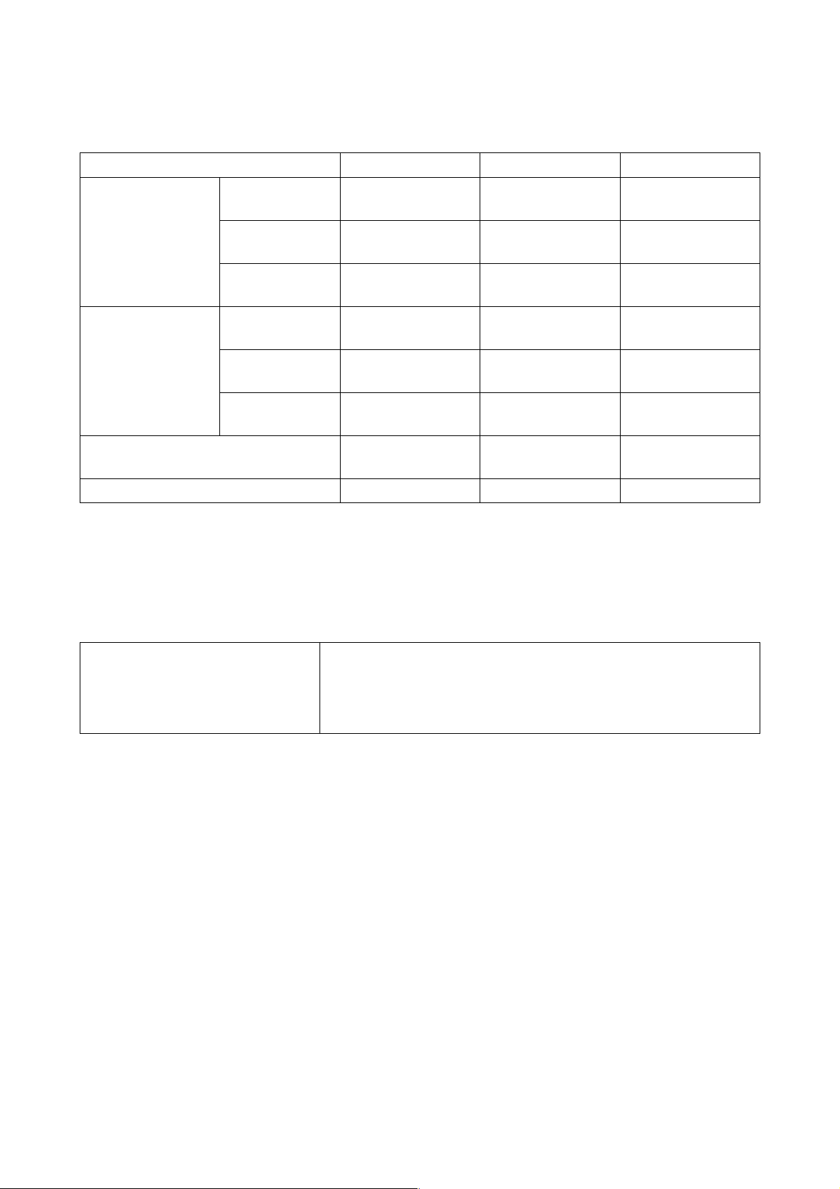
Dimensions (W x D x H)
MFC620CN U.S.A./Canadian models and FAX2440C:
17.3 x 13.7 x 6.5 inches (438 x 347 x 165 mm)
(with paper tray and document 17.9 x 17.9 x 6.5 inches (454 x 455 x 165 mm)
stopper opened)
14.8" (375 mm)
17.9" (455 mm)
13.7" (347 mm)
6.5"
(165 mm)
MFC620CN European/Asian models and MFC420CN:
14.7 x 13.6 x 6.5 inches (373 x 345 x 165 mm)
(with paper tray and document 14.8 x 17.9 x 6.9 inches (375 x 455 x 174 mm)
stopper opened)
6.5"
(165 mm)
MFC210C and DCP310CN/110C:
14.7 x 13.6 x 5.3 inches (373 x 345 x 135 mm)
(with paper tray opened) 14.7 x 17.8 x 5.3 inches (373 x 453 x 135 mm)
5.3"
(135 mm)
14.2" (361 mm)
14.7" (373 mm)
17.3" (438 mm)
14.8" (375 mm)
14.2" (361 mm)
14.7" (373 mm)
6.9"
(174 mm)
6.9"
(174 mm)
12.7" (322 mm)
13.6" (345 mm)
17.9" (455 mm)
13.7" (347 mm)
12.7" (322 mm)
13.6" (345 mm)
Weight
MFC620CN:
14.2" (361 mm)
14.7" (373 mm)
(Machine proper) 13.4 lb. (6.1 kg) U.S.A./Canadian models
13.2 lb. (6 kg) European/Asian models
(In package)
17.6 lb. (8 kg) U.S.A./Canadian models
18.9 lb. (8.6 kg) European/Asian models
2-2 Confidential
12.7" (322 mm)
13.6" (345 mm)
17.8" (453 mm)
Page 24
2.1.2 Paper Specifications
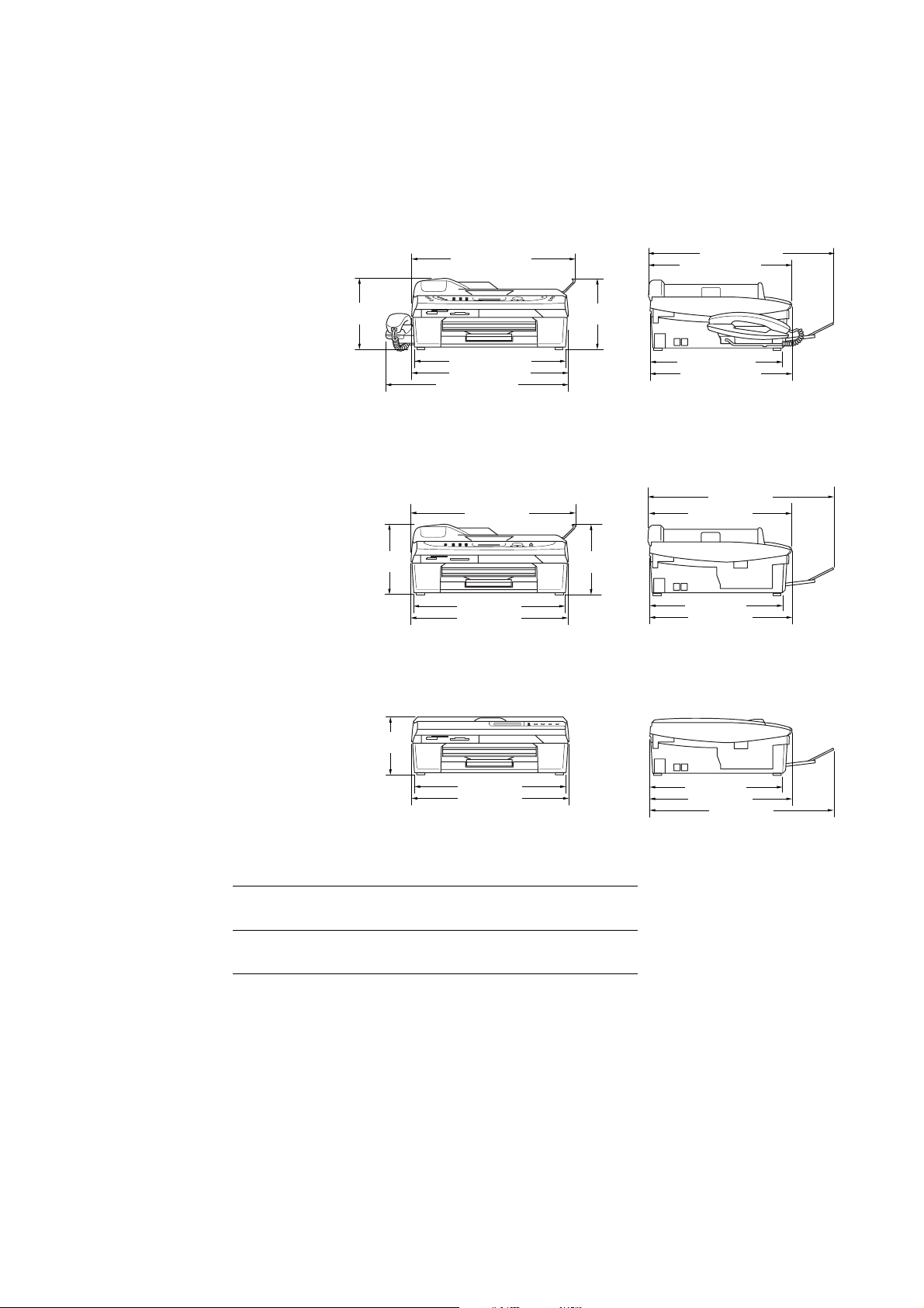
Recommended Paper
Brother Paper
Transparencies: 3M Transparency Film
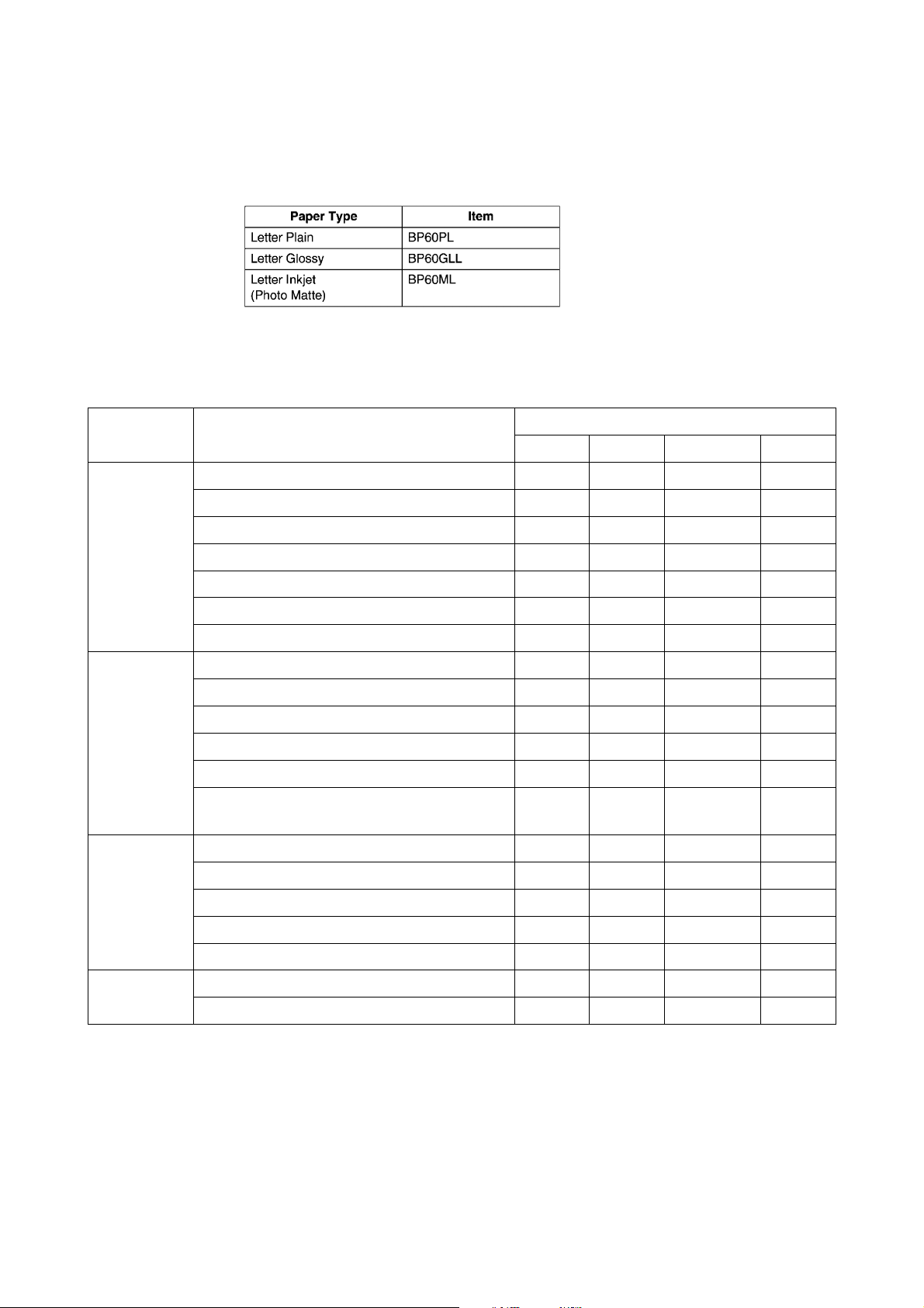
Paper Type and Size for Each Operation
Paper Type Paper Size
Fax Copy PhotoCapture Printer
Cut Sheet Letter 8 1/2" x 11" (216 x 279 mm) Yes Yes Yes Yes
A4 8.3" x 11.7" (210 x 297 mm) Yes Yes Yes Yes
Legal 8 1/2" x 14" (216 x 356 mm) Yes Yes - Yes
Executive 7 1/4" x 10 1/2" (184 x 267 mm) - - - Yes
JIS B5 7.2" x 10.1" (182 x 257 mm) - - - Yes
A5 5.8" x 8.3" (148 x 210 mm) - Yes - Yes
A6 4.1" x 5.8" (105 x 148 mm) - - - Yes
Cards Photo 4" x 6" (102 x 152 mm) - Yes Yes Yes
Photo L 3 1/2" x 5" (89 x 127 mm) - - - Yes
Photo 2L 5" x 7" (127 x 178 mm) - - Yes Yes
Index Card 5" x 8" (127 x 203 mm) - - - Yes
Post Card 1 3.9" x 5.8" (100 x 148 mm) - - - Yes
Post Card 2
(Double)
Envelopes C5 Envelope 6.4" x 9" (162 x 229 mm) - - - Yes
5.8" x 7.9" (148 x 200 mm) - - - Yes
Usage
DL Envelope 4.3" x 8.7" (110 x 220 mm) - - - Yes
COM-10 4 1/8" x 9 1/2" (105 x 241 mm) - - - Yes
Monarch 3 7/8" x 7 1/2" (98 x 191 mm) - - - Yes
JE4 Envelope 4.1" x 9.3" (105 x 235 mm) - - - Yes
Transparencies Letter 8 1/2" x 11" (216 x 279 mm) - Yes - Yes
A4 8.3" x 11.7" (210 x 297 mm) - Yes - Yes
2-3 Confidential
Page 25
Paper Weight, Thickness and Capacity
Paper Type Weight Thickness No. of sheets
Cut Sheet Plain Paper 17 to 32 lb
(64 to 120 g/m
Inkjet Paper 17 to 53 lb
(64 to 200 g/m
Glossy Paper Up to 58 lb
(Up to 220 g/m
Cards Photo Card Up to 64 lb
(Up to 240 g/m
Index Card Up to 32 lb
(Up to 120 g/m
Post Card Up to 53 lb
(Up to 200 g/m
2
)
2
)
2
2
2
2
0.003" to 0.006"
(0.08 to 0.15 mm)
0.003" to 0.01"
(0.08 to 0.25 mm)
Up to 0.01"
)
(Up to 0.25 mm)
Up to 0.01"
)
(Up to 0.28 mm)
Up to 0.006"
)
(Up to 0.15 mm)
Up to 0.01"
)
(Up to 0.23 mm)
Envelopes - Up to 0.02"
(Up to 0.52 mm)
Transparencies - - 10
* Up to 50 sheets for Legal size paper (20 lb).
* Up to 100 sheets of 20 lb.
100
20
20
20
30
30
10
Paper Capacity of the Output Paper Support
Output Paper Support Up to 25 sheets of 20 lb (Letter)
n Transparencies or glossy paper must be picked up from the
output paper support one page at a time to avoid smudging.
n Legal paper cannot be stacked on the output paper support.
2-4 Confidential
Page 26

Do not use paper or envelopes:
n that are damaged, curled, wrinkled, or irregularly shaped
0.04 in.
or longer
0.04 in.
or longer
n that are extremely shiny or highly textured
n that were previously printed by a printer
n that cannot be arranged uniformly when stacked
n that are made with a short grain
Do not use envelopes:
n that are of a baggy construction
n that are embossed (have raised writing on them)
n that have clasps on them
n that are not sharply creased
n that are preprinted on the inside
2-5 Confidential
Page 27
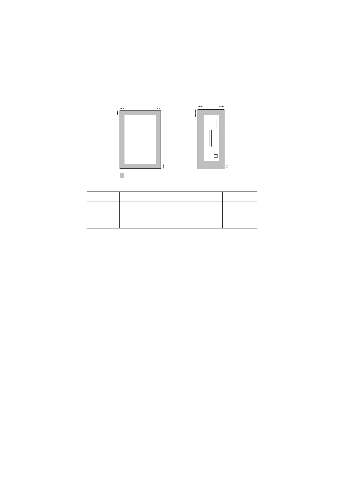
2.1.3 Printable Area
The printable area depends on the settings in the application you are using. The figures below show the
unprintable areas on cut sheet paper and envelopes.
Cut Sheet Paper Envelopes
(3) (4)
(1) (1)
(2) (2)
unprintable area
Paper (1) Top (2) Bottom (3) Left (4) Right
(3) (4)
Cut sheet
Envelopes 0.47 in. 0.94 in. 0.12 in. 0.12 in.
0.12 in.
(0 in.)*
0.12 in.
(0 in.)*
0.12 in.
(0 in.)*
0.12 in.
(0 in.)*
* When you set the Borderless feature to On.
Printable area depends on the Printer driver settings.
The figures above are approximate and the printable area may
vary depending on the type of cut sheet paper you are using.
2-6 Confidential
Page 28

2.2 SPECIFICATIONS LIST
(
)
(
)
(
)
(
)
p
p
MFC210C/MFC420CN/MFC410CN
USA EUR ASIA/OCE/C H N USA EUR ASIA/OCE/CHN
Model name
GENERAL
Print Engine
Technology
Scanning Method
CPU Speed
Back up Clock
Operating Environment
Temperature
(BestPrintQu a lity)
Humidity
On/Off Switch
Demo Model
Panel Key for demo sheet
Simultaneous Operation
Test Sheet
Min. Input of ADF
( Width/Height)
Max. Input of ADF
( Width/Height)
Max. Input of Glass
( Width/Height)
Min. Output of Auto Cut
sheet
Feeder
Width/Height
Max. Output o f Au to C ut
sheet
Feeder
Width/Height
Min. Output of Manual
Feed Slot
Width/Height
Max. Output of Manual
Feed Slot
Width/Height
Min. Output of Multi-
ose
Pur
Max. Output of Multi-
ose
Pur
MFC-210C MFC-210C MFC-210C MFC-420CN MFC-410CN MFC-410CN
BH3 (KKCMY)
74 nozzles/line
Inkjet Inkjet Inkjet Inkjet Inkjet Inkjet
CISCISCISCISCISCIS
RISC 128MHz RISC 128MHz RISC 128MHz RISC 128MHz RISC 128MHz RISC 128MHz
1 hour 1 hour 1 hour 1 hour 1 hour 1 hour
5 - 35 (20-33)
degrees
Centigrade
20 - 80 %
(without
condensation)
Yes Yes Yes Yes Yes Yes
Yes - - Yes - -
Press[Copy]
&[Fax] mode
key at the
same time.
Yes Yes Yes Yes Yes Yes
Yes:Print
Quality/Alignm
ent (in Ink
Key)
8.5"/11.7",
216/297mm
3.5"/5.0",
89/127mm
8.5"/14.0",
216/356mm
BH3 (KKCMY)
74 nozzles/line
5 - 35 (20-33)
degrees
Centigrade
20 - 80 %
(without
condensation)
Yes:Print
Quality/Alignm
ent (in Ink
Key)
---
---
8.5"/11.7",
216/297mm
3.5"/5.0",
89/127mm
8.5"/14.0",
216/356mm
BH3 (KKCMY)
74 nozzles/line
5 - 35 (20-33)
degrees
Centigrade
20 - 80 %
(without
condensation)
--
Yes:Print
Quality/Alignm
ent (in Ink
8.5"/11.7",
216/297mm
3.5"/5.0",
89/127mm
8.5"/14.0",
216/356mm
------
------
------
------
Key)
BH3 (KKCMY)
74 nozzles/line
5 - 35 (20-33)
degrees
Centigrade
20 - 80 %
(without
condensation)
Press[Copy]
&[Fax] mode
key at the
same time.
Yes:Print
Quality/Alignm
ent (in Ink
Key)
5.8"/5.8"(147/1
47mm)
8.5"/14"
(216/356mm)
8.5"/11.7",
216/297mm
3.5"/5.0",
89/127mm
8.5"/14.0",
216/356mm
BH3 (KKCMY)
74 nozzles/line
5 - 35 (20-33)
degrees
Centigrade
20 - 80 %
(without
condensation)
Yes:Print
Quality/Alignm
ent (in Ink
Key)
8.5"/11.7",
216/297mm
3.5"/5.0",
89/127mm
8.5"/14.0",
216/356mm
BH3 (KKCMY)
74 nozzles/line
5 - 35 (20-33)
degrees
Centigrade
20 - 80 %
(without
condensation)
--
Yes:Print
Quality/Alignm
ent (in Ink
Key)
--
--
8.5"/11.7",
216/297mm
3.5"/5.0",
89/127mm
8.5"/14.0",
216/356mm
(1/14)
2-7 Confidential
Page 29

Model name
/
/
/
/
Sheet Weight (Paper tray)
Sheet Weight
(2nd Paper tray)
Sheet Weight (ADF)
Sheet Weight (Manual
Feed Slot)
Sheet Weight (MP Tray)
ADF (pages)
(2/14)
USA EUR ASIA/OCE/CHN USA EUR ASIA/OCE/CHN
MFC-210C MFC-210C MFC-210C MFC-420CN MFC-410CN MFC-410CN
64 -220 g/m2
( 17 - 58 lb. )
------
---
------
------
---
64 -220 g/m2
( 17 - 58 lb. )
64 -220 g/m2
( 17 - 58 lb. )
64 -220 g/m2
( 17 - 58 lb. )
64-90g/mm2
(17-24lb.)
Yes (10)
64 -220 g/m2
( 17 - 58 lb. )
64 -220 g/m2
( 17 - 58 lb. )
--
--
Paper Capacity (sheets)
100 (80 gsm) 100 (80 gsm) 100 (80 gsm) 100 (80 gsm) 100 (80 gsm) 100 (80 gsm)
Output Paper Capacity
(sheets) 25 25 25 25 25 25
Optional Paper Tray
(sheets)
------
Brother Paper
(for Plain,Glossy and
Inkjet)
Recommended Paper
(Only for Transparency)
LCD Size
LTR Plain /
LTR Glossy/
LTR Inkjet
3M 3410
Transparency
film
Standard 16
x 1 line
A4 Plain /
A4 Glossy/
A4 Inkjet
3M 3410
Transparency
film
Standard 16
x 1 line
A4 Plain /
A4 Glossy/
A4 Inkjet
3M 3410
Transparency
film
Standard 16
x 1 line
LTR Plain /
LTR Glossy/
LTR Inkjet
3M 3410
Transparency
film
Standard 16
x 2 lines
A4 Plain /
A4 Glossy/
A4 Inkjet
3M 3410
Transparency
film
Standard 16
x 2 lines
A4 Plain /
A4 Glossy/
A4 Inkjet
3M 3410
Transparency
film
Standard 16
x 2 lines
LCD Back Light & Color
------
On-Screen Programming
LCD Language
Illuminated Mode Key
Memory Capacity
(physical: Mbytes)
Yes Yes Yes Yes Yes Yes
English
(+French for
CAN model)
PCC/Copy/Fax
/Scan
RAM 8MB
ROM 2MB
Depending on
countries
PCC/Copy/Fax
Scan
RAM 8MB
ROM 2MB
English
PCC/Copy/Fax
Scan
RAM 8MB
ROM 2MB
English
(+French for
CAN model)
PCC/Copy/Fax
Scan
RAM 16MB
ROM 8MB*
Depending on
countries
PCC/Copy/Fax
Scan
RAM 16MB
ROM 8MB
English
PCC/Copy/Fax
/Scan
RAM 16MB
ROM 8MB
Memory Backup (with
battery 24hour)
Back Up Print: ON/OFF
Feature (in function Menu)
Memory Security
Transmission Lock
------
Yes Yes Yes Yes Yes Yes
------
- Yes Yes - Yes Yes
*4MB (w/o demonstration program)
2-8 Confidential
Page 30

(3/14)
g
p
g)
USA EUR ASIA/OCE/CHN USA EUR ASIA/OCE/CHN
Model name
Dimensions w/ Carton
(WxDxH)=>Please refer to
"Logistic Information" on
Sales Data Bank.
Dimensions w/o Carton
(WxDxH) * tray is not
opened )=>Please refer
to "Logistic Information"
Dimensions w/o Carton
with tray is opend
=>refer to "Logistic
Weight w/ Carton
Please refer to "Logistic
Information"
Weight w/o Carton
w/o tray Please refer to
istic Information"
"Lo
Body Color = Top Cover
Body Color = Pane l cover Black Black Black Metallic Blue Metallic Blue Metallic Blue
Body Color = Bottom
Cover
Body Color = Bottom
Cover (Engine unit)
MFC-210C MFC-210C MFC-210C MFC-420CN MFC-410CN MFC-410CN
W 420 x
D 200 x H 380
W 373 x
D 345 x H 135
W 373 x
D 453 x H 135
6.6kg 7kg 7kg 7.5kg 6.5kg 6.5kg
5.5kg 5.5kg 5.5kg 6kg 5.5kg 5.5kg
BHmini Silver BHmini Silver BHmini Silver Metallic Blue Metallic Blue Metallic Blue
Dark gray Dark gray Dark gray Dark gray Dark gray Dark gray
Dark gray Dark gray Dark gray Dark gray Dark gray Dark gray
W 500 x
D 200 x H 450
W 373 x
D 345 x H 135
W 373 x
D 453 x H 135
W 500 x
D 200 x H 450
W 373 x
D 345 x H 135
W 373 x
D 453 x H 135
W 420 x
D 200 x H 380
W 373 x
D 347 x H 165
W 375 x
D 455 x H 165
W 500 x
D 200 x H 450
W 373 x
D 347 x H 165
W 373 x
D 453 x H 135
W 500 x
D 200 x H 450
W 373 x
D 347 x H 165
W 373 x
D 453 x H 135
Power Source
Power
Consumption(Power OFF/
Power Save(CPU Sleep)/
Standby/ Peak)
Energy Star Compliant
( USA Only )
Machine Noise
(Standby/Peak ex. In
rintin
Total print pages
Copy pages
PC print pages
Fax RX pages
PCC pages
Ink Gauge Indication
AC 120 V
50/60Hz
(3.0Wh / - /
7.0Wh /
20.0Wh)
Yes Yes Yes Yes Yes Yes
better than
35dBA/45dBA
Yes Yes Yes Yes Yes Yes
Yes Yes Yes Yes Yes Yes
Yes Yes Yes Yes Yes Yes
Yes Yes Yes Yes Yes Yes
Yes Yes Yes Yes Yes Yes
Yes (in Ink
Key/ Status
Monitor)
AC 220-240 V
50/60Hz
(3.0Wh / - /
7.0Wh /
20.0Wh)
better than
35dBA/45dBA
Yes (in Ink
Key/ Status
Monitor)
AC 220-240 V
50/60Hz
(3.0Wh / - /
7.0Wh /
20.0Wh)
better than
35dBA/45dBA
Yes (in Ink
Key/ Status
Monitor)
AC 120 V
50/60Hz
(3.5Wh / - /
8.0Wh /
25.0Wh)
better than
35dBA/45dBA
Yes (in Ink
Key/ Status
Monitor)
AC 220-240 V
50/60Hz
(4.0Wh / - /
9.0Wh /
19.0Wh)
better than
35dBA/45dBA
Yes (in Ink
Key/ Status
Monitor)
AC 220-240 V
50/60Hz
(4.0Wh / - /
9.0Wh /
19.0Wh)
better than
35dBA/45dBA
Yes (in Ink
Key/ Status
Monitor)
2-9 Confidential
Page 31

Model name
LIST/REPORT
Activity Report/Jour-l
Report
Transmission Verification
Report
Cover page
Help List
(4/14)
USA EUR
ASIA/OCE/CHN
USA EUR
MFC-210C MFC-210C MFC-210C MFC-420CN MFC-410CN MFC-410CN
Yes (up to
200)
Yes (in Menu
Table)
------
Yes (in
Reports menu)
Yes (up to
200)
Yes (in Menu
Table)
Yes (in
Reports menu)
Yes (up to
200)
Yes (in Menu
Table)
Yes (in
Reports menu)
Yes (up to
200)
Yes (in Menu
Table)
Yes (in
Reports menu)
Yes (up to
200)
Yes (in Menu
Table)
Yes (in
Reports menu)
ASIA/OCE/CHN
Yes (up to
200)
Yes (in Menu
Table)
Yes (in
Reports menu)
Call Back Message
Caller ID List
Quick Dial List
Quick Dial List ( New )
New =>Empty box is not
printed out.
Tel Index List
Memory Status List
System Setup(User
Setting) List
Order Form
INTERFACE
Exter-l TAD Interface
Host Interface
LAN
Cable included
PictBridge
------
Yes(in
CallerID
Menu)
------
Yes (in
Reports menu)
------
------
---
------
Yes Yes Yes Yes Yes Yes
USB1.1/2.0(@
FULL-
SPEEED)
- - - Yes Yes Yes
------
------
--
Yes (in
Reports menu)
USB1.1/2.0(@
FULL-
SPEEED)
Yes (in
Reports menu)
USB1.1/2.0(@
FULL-
SPEEED)
Yes(in
CallerID
Menu)
Yes (in
Reports menu)
Yes (in
Reports Menu)
USB1.1/2.0(@
FULL-
SPEEED)
--
Yes (in
Reports menu)
Yes (in
Reports Menu)
USB1.1/2.0(@
FULL-
SPEEED)
Yes (in
Reports menu)
Yes (in
Reports Menu)
USB1.1/2.0(@
FULL-
SPEEED)
Acceptable Media Card
CF/MS/SD/SM
/xD
CF/MS/SD/SM
/xD
CF/MS/SD/SM
/xD
CF/MS/SD/SM
/xD
CF/MS/SD/SM
/xD
CF/MS/SD/SM
/xD
2-10 Confidential
Page 32

Model name
S
pag
y
y
y
y
y
y
;
)
p
)
SUPPLIES/ OPTION
Bundled Ink (Life / Yield)
(5/14)
USA EUR
ASIA/OCE/CHN
USA EUR
MFC-210C MFC-210C MFC-210C MFC-420CN MFC-410CN MFC-410CN
BK:500pages
(Normal 5%)
BK:500pages
(Normal 5%)
BK:500pages
(Normal 5%)
BK:500pages
(Normal 5%)
BK:500pages
(Normal 5%)
ASIA/OCE/CHN
BK:500pages
(Normal 5%)
Supply Ink Cartridge (Life
/ Yield)
Supply Ink Cartridge (Life
/ Yield) *HighCapacity
Options
SERVICE
INFORMATION
Monthly Volume
Machine Life (year)
Periodical Replacement
Parts for Laser
Fixing Unit
Separation Pad Assy
Paper Pick-up Roller Assy
Scanner Unit
MTBF (Mean Time
Between Failures
MTTR (Mean Time To BE
Re
aired
Ozone Emission;
Printer
Scanner (Mono/Color)
TELEPHONE
Handset
Hook
Off Hook Alarm
Duplex Speaker Phone
Power Failure Phone
Power Failure Dialing
Chain Dialing
Automatic Redial
Recall (For ASIA)
PBX Feature
( EUR&ASIA )
C/M/Y:400pag
es(Normal 5%)
BK:500pages
(Normal 5%)
C/M/Y:400pag
es(Normal 5%)
2500
30,000 pages
(print)/50,000
pages (scan)
or 5
4,000 hours 4,000 hours 4,000 hours 4,000 hours 4,000 hours 4,000 hours
30 min. 30 min. 30 min. 30 min. 30 min. 30 min.
Yes - Yes Yes - Yes
Yes Yes Yes Yes Yes Yes
Yes
(1time/5min)
C/M/Y:400pag
es(Normal 5%)
BK:500pages
(Normal 5%)
C/M/Y:400pag
es(Normal 5%)
------
------
es 2500 pages 2500 pages 2500 pages 2500 pages 2500 pages
30,000 pages
(print)/50,000
pages (scan)
ears
------
------
------
------
------
------
------
------
------
------
------
------
------
------
-Yes
or 5
Yes
(3time/5min)
ears
C/M/Y:400pag
es(Normal 5%)
BK:500pages
(Normal 5%)
C/M/Y:400pag
es(Normal 5%)
30,000 pages
(print)/50,000
pages (scan)
or 5
ears
Yes
(3times/5min)
-
C/M/Y:400pag
es(Normal 5%)
BK:500pages
(Normal 5%)
C/M/Y:400pag
es(Normal 5%)
30,000 pages
(print)/50,000
pages (scan)
or 5
Yes
(1time/5min)
C/M/Y:400pag
es(Normal 5%)
BK:500pages
(Normal 5%)
C/M/Y:400pag
es(Normal 5%)
30,000 pages
(print)/50,000
pages (scan)
ears
-Yes
or 5
Yes
(3time/5min)
ears
C/M/Y:400pag
es(Normal 5%)
BK:500pages
(Normal 5%)
C/M/Y:400pag
es(Normal 5%)
30,000 pages
(print)/50,000
pages (scan)
or 5
Yes
(3times/5min)
-
ears
2-11 Confidential
Page 33

Model name
y)
y)
y )
y )
y )
y )
y )
y )
(
)
Handset Volume
Speaker Volume
Ring Volume
Hold/Mute Key
(6/14)
USA EUR
ASIA/OCE/CHN
USA EUR
MFC-210C MFC-210C MFC-210C MFC-420CN MFC-410CN MFC-410CN
- - - - - -
Yes (3 steps +
OFF)
Yes (3 steps +
OFF)
Yes (3 steps +
OFF)
Yes (3 steps +
OFF)
- - - - - -
Yes (3 steps +
OFF)
Yes (3 steps +
OFF)
Yes (3 steps +
OFF)
Yes (3 steps +
OFF)
Yes (3 steps +
OFF)
Yes (3 steps +
OFF)
ASIA/OCE/CHN
Yes (3 steps +
OFF)
Yes (3 steps +
OFF)
Music on Hold
Monitoring the Line on
Hold with Music
One-Touch Dial
Speed Dial
Figures of One-Touch &
Speed Dial 20 digits 20 digits 20 digits 20 digits 20 digits 20 digits
Resisterable Number Of
Characters
Group Dial ( Up to X
groups )
Telephone Index
( Search/Speed dial key )
Caller ID
Call Waiting Caller ID
Call waiting Ready ( Only
for USA )
Distinctive Ringing
- - - - - -
- - - - - -
------
20 20 20 80 80 80
15 characters 15 charact ers 15 characters 15 charact ers 15 characters 15 characters
Yes (6) Yes (6) Yes (6) Yes (6) Yes (6) Yes (6)
Yes Yes Yes Yes Yes Yes
Yes -
------
- - -- - -
Yes
Yes (UK,DE N
only)
Yes
(ARL/NZ/SIN/
HK only)
Yes
(ARL/NZ/SIN/
HK onl
Yes -
Yes
Yes (UK,DE N
only)
Yes
(ARL/NZ/SIN/
HK only)
Yes
(ARL/NZ/SIN/
HK onl
COLOR FAX
Modem Speed(bps)
Transmission Speed(sec.)
ITU-T Group
Coding Method
Fax/Tel Switch
Super Fine
Gray Scale
Contrast
(Auto/S.Light/S.Dark)
Dual Access
Enhanced Remote
Activate
Station ID
20digits/20characters
14,400(Fax) 14,400(Fax) 14,400(Fax) 14,400(Fax) 14,400(Fax) 14,400(Fax)
Approx.6
(Brother#1,MM
R)
G3 G3 G3 G3 G3 G3
Mono:MH/MR/
MMR,
Color:JPEG
Yes (Hook
key)
Yes ( TX &
RX:B&W onl
Mono:64,
Color:256
Yes Yes Yes Yes Yes Yes
Yes (B&W
only)
Yes Yes Yes Yes Yes Yes
Yes Yes Yes Yes Yes Yes
Approx.6
(Brother#1,MM
R)
Mono:MH/MR/
MMR,
Color:JPEG
Yes (Tel key)
Yes ( TX &
RX:B&W onl
Mono:64,
Color:256
Yes (B&W
only)
Approx.6
(Brother#1,MM
R)
Mono:MH/MR/
MMR,
Color:JPEG
Yes (Hook
key)
Yes ( TX &
RX:B&W onl
Mono:64,
Color:256
Yes (B&W
only)
Approx.6
(Brother#1,MM
R)
Mono:MH/MR/
MMR,
Color:JPEG
Yes (Hook
key)
Yes ( TX &
RX:B&W onl
Mono:64,
Color:256
Yes (B&W
only)
Approx.6
(Brother#1,MM
R)
Mono:MH/MR/
MMR,
Color:JPEG
Yes (Tel key)
Yes ( TX &
RX:B&W onl
Mono:64,
Color:256
Yes (B&W
only)
Approx.6
(Brother#1,MM
R)
Mono:MH/MR/
MMR,
Color:JPEG
Yes (Hook
key)
Yes ( TX &
RX:B&W onl
Mono:64,
Color:256
Yes (B&W
only)
2-12 Confidential
Page 34

Model name
)
(
g
(
)
g
)
)
)
)
)
)
)
)
)
)
Remote Maintenance
RX Mode Indication
Resolution Indication
Paper Handling Size
Ducument Scanning Width
Delayed Timer
(up to 50:B&W only)
Polled Sending (type)
*B&W only
Next-Fax Reservation
Batch Transmission
Quick-Scan(Memory
transmission)
Memory Transmission
ITU-T Test Chart
Memory Transmission
Brother Chart/ MMR
ECM (Error Correction
Mode)
Error Re-Transmission
Broadcasting (Speed+
OneTouch+Manual
Manual Broadcasting
Easy Rece ive /F a x D e te c t
Polling Receiving (type)
*B&W only
Auto Reduction
Out-of-Paper Reception
(ITU-T Test Chart
#1/MMR
Out-of-Paper Reception
(Brother Chart/ MMR)
Remote Access
Fax Retrieval
Fax Forwarding
Paging
Color FAX (Document
Send/Receive)
Color FAX (Memory
Send/Receive)
(7/14)
USA EUR
ASIA/OCE/CHN
USA EUR
MFC-210C MFC-210C MFC-210C MFC-420CN MFC-410CN MFC-410CN
- - - Yes Yes Yes
LCD LCD LCD LCD LCD LCD
LCD LCD LCD LCD LCD LCD
LTR, A4 LTR, A4 LTR, A4
208mm 208mm 208mm 208mm 208mm 208mm
- - - Yes Yes Yes
- - - Yes(Std.)
Yes (Dual
Access)
Yes (Dual
Access)
Yes (Dual
Access)
---
Approx.4.72se
c/page@LTR
Approx. 5.02
sec./page@A4
Up to 170
Pa
UP to 200
Pa
Yes Yes Yes Yes Yes Yes
Yes (70
locations
Yes(50
locations )
Yes Yes Yes Yes Yes Yes
Yes Yes Yes Yes Yes Yes
Up to 170
Page
UP to 200
Pages
Yes/Yes (ITU-
color FAX)
No / Yes (ITU-
color FAX)
Approx.4.72se
c/page@LTR
Approx. 5.02
sec./page@A4
Up to 170
e
Pages
UP to 200
es
------
---Yes (Std/Seq)
- - - Yes Yes Yes
---
---
---Yes--
Pages
Yes (70
locations
Yes(50
locations )
Up to 170
Pages
UP to 200
Pages
Yes/Yes (ITU-
color FAX)
No / Yes (ITU-
color FAX)
Approx.4.72se
c/page@LTR
Approx. 5.02
sec./page@A4
Up to 170
Pages
UP to 200
Pages
Yes (70
locations
Yes(50
locations )
Up to 170
Pages
UP to 200
Pages
Yes/Yes (ITU-
color FAX)
No / Yes (ITU-
color FAX)
LTR,
A4+LEGAL(wit
hADF
Yes (Dual
Access)
Yes (B&W
only /not color)
Approx.4.72se
c/page@LTR
Approx. 5.02
sec./page@A4
Up to 400
Pages
UP to 480
Pages
Yes (130
locations
Yes(50
locations )
Up to 400
Pages
UP to 480
Pages
Yes (B&W
only)
Yes (B&W
only)
Yes/Yes (ITU-
color FAX)
No / Yes (ITU-
color FAX)
LTR, A4 LTR, A4
Yes
(Std/Secure)
Yes (Dual
Access)
Yes (B&W
only /not color)
Approx.4.72se
c/page@LTR
Approx. 5.02
sec./page@A4
Up to 400
Pages
UP to 480
Pages
Yes (130
locations
Yes(50
locations )
Yes
(Std/Seq/Sec u
re/Timer
Up to 400
Pages
UP to 480
Pages
Yes (B&W
only)
Yes (B&W
only)
Yes/Yes (ITU-
color FAX)
No / Yes (ITU-
color FAX)
ASIA/OCE/CHN
Yes
(Std/Secure)
Yes (Dual
Access)
Yes (B&W
only /not color)
Approx.4.72se
c/page@LTR
Approx. 5.02
sec./page@A4
Up to 400
Pages
UP to 480
Pages
Yes (130
locations
Yes(50
locations )
Yes
(Std/Seq/Sec u
re/Timer
Up to 400
Pages
UP to 480
Pages
Yes (B&W
only)
Yes (B&W
only)
Yes/Yes (ITU-
color FAX)
No / Yes (ITU-
color FAX)
2-13 Confidential
Page 35

Model name
)
(
)
COLOR PRINTER
Color/Mono
Resolution(dpi)
Speed(ppm) Simple
First print out time (from
READY mode *2
Warm up Time ( from
SLEEP mode )
Emulation
Resident Fonts
Fonts Disk Based
Paper Handling Size
(Paper Tray)
Paper Handling Size
(2nd Tray)
(8/14)
USA EUR
ASIA/OCE/CHN
USA EUR
MFC-210C MFC-210C MFC-210C MFC-420CN MFC-410CN MFC-410CN
Color Color Color Color Color Color
up to
1200x6000 dpi
20/15ppm
(Mono/Color:
600x150 dpi)
------
------
------
------
Yes (35
TrueType)
A4, LTR, LGL,
EXE, JISB5, A5,
A6,
Photo(4x6"/102x
152mm),
Indexcard(5x8"/1
27x203mm),
Photo L
(3.5x5"/89x127m
m),
Photo2L(5x7"/12
7x178mm), Post
Card
1(3.9x5.8"/100x1
48mm), Post
Card 2
(Double)(5.8x7.8"
/148x200mm),
C5 Envelope,
Com-10, DL
Envelope, Morch, JE4
Envelope.
- - - - - -
up to
1200x6000 dpi
20/15ppm
(Mono/Color:
600x150 dpi)
Yes (35
TrueType)
A4, LTR,
LGL, EXE,
JISB5, A5, A6,
Photo(4x6"/102x
152mm),
Indexcard(5x8"/1
27x203mm),
Photo L
(3.5x5"/89x127m
m),
Photo2L(5x7"/12
7x178mm), Post
Card
1(3.9x5.8"/100x1
48mm),
Post Card 2
(Double)(5.8x7.8"
/148x200mm),
C5 Envelope,
Com-10,
DL Envelope,
Mo-rch,
JE4 Envelope.
ASIA/OCE/CHN
up to
1200x6000 dpi
20/15ppm
(Mono/Color:
600x150 dpi)
Yes (35
TrueType)
A4, LTR,
LGL, EXE,
JISB5, A5, A6,
Photo(4x6"/102x
152mm),
Indexcard(5x8"/1
27x203mm),
Photo L
(3.5x5"/89x127m
m),
Photo2L(5x7"/12
7x178mm), Post
Card
1(3.9x5.8"/100x1
48mm),
Post Card 2
(Double)(5.8x7.8"
/148x200mm),
C5 Envelope,
Com-10,
DL Envelope,
Mo-rch,
JE4 Envelope.
Paper Handling Size
Manual Slots
- - - - - -
Paper Handling Size (MP)
- - - - - -
Media Type (Paper Tray)
Media Type (2 nd Paper
Tray)
Media Type
(Manual Slots)
Media Type (MP Tray)
Plain, Inkjet,
Glossy,
Transparency
Plain, Inkjet,
Glossy,
Transparency
Plain, Inkjet,
Glossy,
Transparency
Plain, Inkjet,
Glossy,
Transparency
Plain, Inkjet,
Glossy,
Transparency
Plain, Inkjet,
Glossy,
Transparency
- - - - - -
- - - - - -
- - - - - -
2-14 Confidential
Page 36

Model name
y)
y)
y)
Print Paper Margin (upper,
lower, left, right)
Variable Dot Print
Minimum Droplet Size
Shingling Print
Color Enhancement
COLOR COPY
Color/Mono
Speed (cpm) *time
culcurated excluding
paper feeding
**EU's defult is culcurated
by "nomal mode"speed.
Warm up Time (from
SLEEP mode)
Multi Copy (Stack)
Multi Copy (Sort)
Reduction/Enlargement
(%)
Resolution (dpi)
N in 1
Poster
Image Enhancement
(9/14)
USA EUR
ASIA/OCE/CHN
USA EUR
MFC-210C MFC-210C MFC-210C MFC-420CN MFC-410CN MFC-410CN
Borderless
ON:0, 0, 0,0*
OFF:0.12, 0.12,
0.12,
0,12"/3,3,3,3mm**
* Borderless For
A4
/LTR/A6/Photo(4x6
"/102x152mm),
Indexcard(5x8"/12
7x203mm), Photo
L
(3.5x5"/89x127mm
), Photo
2L(5x7"/127x178m
m), Post Card
1(3.9x5.8"/100x14
8mm), Post Card 2
(Double)(5.8x7.8"/
148x200mm) only
**
0.47x0.95x0.12x0.
12"/12,24,3,3mm
for Envelops
Yes (3 sizes) Yes (3 sizes) Yes (3 sizes) Yes (3 sizes) Yes (3 sizes) Yes (3 sizes)
3 pl 3 pl 3 pl 3 pl 3 pl 3 pl
YesYesYesYesYesYes
Color Color Color Color Color Color
17/11cpm 17/11cpm 17/11cpm 17/11cpm 17/11cpm 17/11cpm
Yes (Up to 99) Yes (Up to 99) Yes (Up to 99) Yes (Up to 99) Yes (Up to 99) Yes (Up to 99)
25 -- 400 in
1% increments
Print: Max.
600x1200 dpi
Scan: Max.
600x1200 dpi
Borderless
ON:0, 0, 0,0*
OFF:0.12, 0.12,
0.12,
0,12"/3,3,3,3mm**
* Borderless For
A4
/LTR/A6/Photo(4x6
"/102x152mm),
Indexcard(5x8"/12
7x203mm), Photo
L
(3.5x5"/89x127mm
), Photo
2L(5x7"/127x178m
m), Post Card
1(3.9x5.8"/100x14
8mm), Post Card 2
(Double)(5.8x7.8"/
148x200mm) only
**
0.47x0.95x0.12x0.
12"/12,24,3,3mm
for Envelops
------
------
---Yes-25 -- 400 in
1% increments
Print: Max.
600x1200 dpi
Scan: Max.
600x1200 dpi
---
25 -- 400 in
1% increments
Print: Max.
600x1200 dpi
Scan: Max.
600x1200 dpi
25 -- 400 in
1% increments
Print: Max.
600x1200 dpi
Scan: Max.
600x1200 dpi
2in1,
4in1(Mono/Col
or, A4/LTR
onl
25 -- 400 in
1% increments
Print: Max.
600x1200 dpi
Scan: Max.
600x1200 dpi
2in1,
4in1(Mono/Col
or, A4/LTR
onl
- - - Yes (3x3) Yes (3x3) Yes (3x3)
------
ASIA/OCE/CHN
Borderless
ON:0, 0, 0,0*
OFF:0.12, 0.12,
0.12,
0,12"/3,3,3,3mm**
* Borderless For
A4
/LTR/A6/Photo(4x6
"/102x152mm),
Indexcard(5x8"/12
7x203mm), Photo
L
(3.5x5"/89x127mm
), Photo
2L(5x7"/127x178m
m), Post Card
1(3.9x5.8"/100x14
8mm), Post Card 2
(Double)(5.8x7.8"/
148x200mm) only
**
0.47x0.95x0.12x0.
12"/12,24,3,3mm
for Envelops
25 -- 400 in
1% increments
Print: Max.
600x1200 dpi
Scan: Max.
600x1200 dpi
2in1,
4in1(Mono/Col
or, A4/LTR
onl
2-15 Confidential
Page 37

Model name
p
)
p
)
g
Paper Handling Size
(Paper Tray)
Paper Handling Size
(2nd Tray)
Paper Handling Size
(Manual Slots)
(10/14)
USA EUR
ASIA/OCE/CHN
USA EUR
MFC-210C MFC-210C MFC-210C MFC-420CN MFC-410CN MFC-410CN
Letter/Legal/A
4/A5/4"x6"(10(
W)x15(H)cm)
- - - - - -
- - - - - -
Letter/Legal/A
4/A5/4"x6"(10(
W)x15(H)cm)
Letter/Legal/A
4/A5/4"x6"(10(
W)x15(H)cm)
Letter/Legal/A
4/A5/4"x6"(10(
W)x15(H)cm)
Letter/Legal/A
4/A5/4"x6"(10(
W)x15(H)cm)
ASIA/OCE/CHN
Letter/Legal/A
4/A5/4"x6"(10(
W)x15(H)cm)
Paper Handling Size (MP)
Media Type (Paper Tray)
Media Type (2nd Tray)
Media Type (Manual
Slots)
Media Type (MP Tray)
Print Paper Margin (upper,
lower, left, right)
Duplex Copy
Resolution Indication
COLOR SCANNER
Color/Mono
Optical Resolution (dpi)
Interpolated Resolution
(dpi)
- - - - - -
Plain, Inkjet,
Glossy,
Transparency
- - - - - -
- - - - - -
- - - - - -
0.12, 0.12,
0.12, 0,12"
(3,3,3,3mm)
------
LCD LCD LCD LCD LCD LCD
Color Color Color Color Color Color
600x2400 dpi 600x2400 dpi 600x2400 dpi 600x2400 dpi 600x2400 dpi 600x2400 dpi
up to
19200x19200
dpi (For XP,
with special
tool.
1200x1200dpi
for XP w/o
special tool)
Plain, Inkjet,
Glossy,
Transparency
0.12, 0.12,
0.12, 0,12"
(3,3,3,3mm)
up to
19200x19200
dpi (For XP,
with special
tool.
1200x1200dpi
for XP w/o
special tool)
Plain, Inkjet,
Glossy,
Transparency
0.12, 0.12,
0.12, 0,12"
(3,3,3,3mm)
up to
19200x19200
dpi (For XP,
with special
tool.
1200x1200dpi
for XP w/o
special tool)
Plain, Inkjet,
Glossy,
Transparency
0.12, 0.12,
0.12, 0,12"
(3,3,3,3mm)
up to
19200x19200
dpi (For XP,
with special
tool.
1200x1200dpi
for XP w/o
special tool)
Plain, Inkjet,
Glossy,
Transparency
0.12, 0.12,
0.12, 0,12"
(3,3,3,3mm)
up to
19200x19200
dpi (For XP,
with special
tool.
1200x1200dpi
for XP w/o
special tool)
Plain, Inkjet,
Glossy,
Transparency
0.12, 0.12,
0.12, 0,12"
(3,3,3,3mm)
up to
19200x19200
dpi (For XP,
with special
tool.
1200x1200dpi
for XP w/o
special tool)
Warm up Time (from
Scanner Lam
Warm up Time
Scanner Lam
Gray Scale
Ducument Scannin
Scan Image
Scan / OCR
Scan to E-mail
Scan to File
Scan to Card
OFF
(from
OFF: Color
------
------
256 256 256 256 256 256
Max. 210mm Max. 210mm Max. 210mm Max. 210mm Max. 210mm Max. 210mm
width
Yes (scan key) Yes (scan key) Yes (scan key) Yes (scan key) Yes (scan key) Yes (scan key)
Yes (scan key) Yes (scan key) Yes (scan key) Yes (scan key) Yes (scan key) Yes (scan key)
Yes (scan key) Yes (scan key) Yes (scan key) Yes (scan key) Yes (scan key) Yes (scan key)
Yes (scan key) Yes (scan key) Yes (scan key) Yes (scan key) Yes (scan key) Yes (scan key)
- - - Yes (scan key) Yes (scan key) Yes (scan key)
2-16 Confidential
Page 38

Model name
Scan speed (Mono/Color)
*@100dpi
(11/14)
USA EUR
ASIA/OCE/CHN
USA EUR
MFC-210C MFC-210C MFC-210C MFC-420CN MFC-410CN MFC-410CN
Max. 3.54/5.58
sec
@Letter_size
Max. 3.76/5.93
sec @A4_size
Max. 3.54/5.58
sec
@Letter_size
Max. 3.76/5.93
sec @A4_size
Max. 3.54/5.58
sec
@Letter_size
Max. 3.76/5.93
sec @A4_size
Max. 3.54/5.58
sec
@Letter_size
Max. 3.76/5.93
sec @A4_size
Max. 3.54/5.58
sec
@Letter_size
Max. 3.76/5.93
sec @A4_size
ASIA/OCE/CHN
Max. 3.54/5.58
sec
@Letter_size
Max. 3.76/5.93
sec @A4_size
Scanner Lamp Switch
(CIS doesn't require switch)
Color Depth (Input/Output)
MESSAGE CENTER
TAD
ICM Recording Time
Toll Saver
Memo/Recording
Conversation
OGM (MC/TAD,F/T)
User Recording OGM
TIME( MC/TAD, F/T )
PC FAX
Supplier
Color/Mono
Sending
Receiving
Protocol Compliance
Broadcasting
Support OS Version
(Refer
to"Application&OS"
sheet)
- - - - - -
36/24 bit color
processing
Brother Brother Brother Brother Brother Brother
Mono Mono Mono Mono Mono Mono
Yes Yes Yes Yes Yes Yes
up to 50 up to 50 up to 50 up to 50 up to 50 up to 50
36/24 bit color
processing
------
------
------
------
------
------
- - - Yes Yes Yes
------
36/24 bit color
processing
36/24 bit color
processing
36/24 bit color
processing
36/24 bit color
processing
Others
------
2-17 Confidential
Page 39

Model name
PHOTO CAPTURE
CENTER
Acceptable Media Card &
Size
(12/14)
USA EUR
ASIA/OCE/CHN
USA EUR
ASIA/OCE/CHN
MFC-210C MFC-210C MFC-210C MFC-420CN MFC-410CN MFC-410CN
SmartMedia
(3.3V):4MB-
128MB
Compact Flash
(Type-1, excl.
Type2/MicroDrive):4MB-2GB
Memory
Stick:16MB-
128MB (Duo with
Adopter)
Memory Stick
Pro:256MB-1GB
(MagicGate:Yes
if not use MG
function)
Secure
Digital
:16MB512MB (MiniSD
with Adopter)
xD Picture
Card:16-512MB
SmarMedia
(3.3V):4MB-
128MB
Compact Flash
(Type-1, excl.
Type2/MicroDrive):4MB-2GB
Memory
Stick:16MB-
128MB (Duo with
Adopter)
Memory Stick
Pro:256MB-1GB
(MagicGate:Yes
if not use MG
function)
Secure
Digital
:16MB512MB (MiniSD
with Adopter)
xD Picture
Card:16-512MB
SmartMedia
(3.3V):4MB-
128MB
Compact Flash
(Type-1, excl.
Type2/MicroDrive):4MB-2GB
Memory
Stick:16MB-
128MB (Duo with
Adopter)
Memory Stick
Pro:256MB-1GB
(MagicGate:Yes
if not use MG
function)
Secure
Digital
:16MB512MB (MiniSD
with Adopter)
xD Picture
Card:16-512MB
SmartMedia
(3.3V):4MB-
128MB
Compact Flash
(Type-1, excl.
Type2/MicroDrive):4MB-2GB
Memory
Stick:16MB-
128MB (Duo with
Adopter)
Memory Stick
Pro:256MB-1GB
(MagicGate:Yes
if not use MG
function)
Secure
Digital
:16MB512MB (MiniSD
with Adopter)
xD Picture
Card:16-512MB
SmartMedia
(3.3V):4MB-
128MB
Compact Flash
(Type-1, excl.
Type2/MicroDrive):4MB-2GB
Memory
Stick:16MB-
128MB (Duo with
Adopter)
Memory Stick
Pro:256MB-1GB
(MagicGate:Yes
if not use MG
function)
Secure
Digital
:16MB512MB (MiniSD
with Adopter)
xD Picture
Card:16-512MB
SmartMedia
(3.3V):4MB-
128MB
Compact Flash
(Type-1, excl.
Type2/MicroDrive):4MB-2GB
Memory
Stick:16MB-
128MB (Duo with
Adopter)
Memory Stick
Pro:256MB-1GB
(MagicGate:Yes
if not use MG
function)
Secure
Digital
:16MB512MB (MiniSD
with Adopter)
xD Picture
Card:16-512MB
Paper Handling Size &
Type (Paper Tray)
Paper Handling Size &
Type (Manual Slots)
Paper Handling Size &
Type (MP)
Print Paper Margin (upper,
lower, left, right)
Available paper size for
full (Max) size printing
Direct Print Size for
A4/LTR
Borderless / Cropping
(Full Auto)
Letter
Glossy/4"x6"(1
0x15cm)
Glossy/5"x7"(1
3x18cm)
Glossy /A4
Glossy/Letter
Plai-4
Plain/Letter
Inkjet/A4
Inkjet/4"x6"(10
x15cm) Inkjet
Letter
Glossy/4"x6"(1
0x15cm)
Glossy/5"x7"(1
3x18cm)
Glossy /A4
Glossy/Letter
Plai-4
Plain/Letter
Inkjet/A4
Inkjet/4"x6"(10
x15cm) Inkjet
Letter
Glossy/4"x6"(1
0x15cm)
Glossy/5"x7"(1
3x18cm)
Glossy /A4
Glossy/Letter
Plai-4
Plain/Letter
Inkjet/A4
Inkjet/4"x6"(10
x15cm) Inkjet
Letter
Glossy/4"x6"(1
0x15cm)
Glossy/5"x7"(1
3x18cm)
Glossy /A4
Glossy/Letter
Plai-4
Plain/Letter
Inkjet/A4
Inkjet/4"x6"(10
x15cm) Inkjet
Letter
Glossy/4"x6"(1
0x15cm)
Glossy/5"x7"(1
3x18cm)
Glossy /A4
Glossy/Letter
Plai-4
Plain/Letter
Inkjet/A4
Inkjet/4"x6"(10
x15cm) Inkjet
Letter
Glossy/4"x6"(1
0x15cm)
Glossy/5"x7"(1
3x18cm)
Glossy /A4
Glossy/Letter
Plai-4
Plain/Letter
Inkjet/A4
Inkjet/4"x6"(10
x15cm) Inkjet
------
------
Borderless
(For all size)
ON:0, 0, 0,0
OFF:0.12,
0.12, 0.12,
0,12"/3,3,3,3m
m
4x6"(10x15cm)
/
5x7"(13x18cm)
only
4x3"(10x8cm)/
5x3.5"(13x9cm
)/
6x4"(15x10cm)
/
7x5"(18x13cm)
/
8"x6"(20x15c
m)
Borderless
(For all size)
ON:0, 0, 0,0
OFF:0.12,
0.12, 0.12,
0,12"/3,3,3,3m
m
4x6"(10x15cm)
/
5x7"(13x18cm)
only
4x3"(10x8cm)/
5x3.5"(13x9cm
)/
6x4"(15x10cm)
/
7x5"(18x13cm)
/
8"x6"(20x15c
m)
Borderless
(For all size)
ON:0, 0, 0,0
OFF:0.12,
0.12, 0.12,
0,12"/3,3,3,3m
m
4x6"(10x15cm)
/
5x7"(13x18cm)
only
4x3"(10x8cm)/
5x3.5"(13x9cm
)/
6x4"(15x10cm)
/
7x5"(18x13cm)
/
8"x6"(20x15c
m)
Borderless
(For all size)
ON:0, 0, 0,0
OFF:0.12,
0.12, 0.12,
0,12"/3,3,3,3m
m
Borderless
(For all size)
ON:0, 0, 0,0
OFF:0.12,
0.12, 0.12,
0,12"/3,3,3,3m
m
Borderless
(For all size)
ON:0, 0, 0,0
OFF:0.12,
0.12, 0.12,
0,12"/3,3,3,3m
m
All size All size All size
4x3"(10x8cm)/
5x3.5"(13x9cm
)/
6x4"(15x10cm)
/
7x5"(18x13cm)
/
8"x6"(20x15c
m)/
Max.Size
4x3"(10x8cm)/
5x3.5"(13x9cm
)/
6x4"(15x10cm)
/
7x5"(18x13cm)
/
8"x6"(20x15c
m)/
Max.Size
4x3"(10x8cm)/
5x3.5"(13x9cm
)/
6x4"(15x10cm)
/
7x5"(18x13cm)
/
8"x6"(20x15c
m)/
Max.Size
Yes/Yes Yes/Yes Yes/Yes Yes/Yes Yes/Yes Yes/Yes
2-18 Confidential
Page 40

Model name
K
p
)
Media Format
(13/14)
USA EUR
ASIA/OCE/CHN
USA EUR
MFC-210C MFC-210C MFC-210C MFC-420CN MFC-410CN MFC-410CN
DPOF, Exif,
DCF
DPOF, Exif,
DCF
DPOF, Exif,
DCF
DPOF, Exif,
DCF
DPOF, Exif,
DCF
ASIA/OCE/CHN
DPOF, Exif,
DCF
Image Format
Print by PCC
Scan to Card
Color Enhancement - - - Yes Yes Yes
Removable Disk Yes
Scan to Card - - - Yes Yes Yes
Network PCC - - - Yes DL only
Photo Print:
JPEG
Scan to Card:
JPEG/PDF
(Color),
TIFF/PDF
(B&W)
(Read/Write)
Photo Print:
JPEG
Scan to Card:
JPEG/PDF
(Color),
TIFF/PDF
(B&W)
Yes
(Read/Write)
Photo Print:
JPEG
Scan to Card:
JPEG/PDF
(Color),
TIFF/PDF
(B&W)
Yes
(Read/Write)
Photo Print:
JPEG
Scan to Card:
JPEG/PDF
(Color),
TIFF/PDF
(B&W)
Yes
(Read/Write)
(FTP browser)
Photo Print:
JPEG
Scan to Card:
JPEG/PDF
(Color),
TIFF/PDF
(B&W)
Yes
(Read/Write)
Yes DL only
(FTP browser)
Photo Print:
JPEG
Scan to Card:
JPEG/PDF
(Color),
TIFF/PDF
(B&W)
Yes
(Read/Write)
Yes DL only
(FTP browser)
NETWOR
Standard/Option( User
tion or Dealer Option
O
Model name
Printer
Scanner
PC FAX
Internet FAX (Firmware)
---
---
---
---
---
------
Yes:Standard Yes:Standard Yes:Standard
Embedded
(NC-110h)
Yes Yes Yes
Yes Yes Yes
Yes Yes Yes
Embedded
(NC-110h)
Embedded
(NC-110h)
Forrmat ( Scan to E-mail
server )
ITU SUB Addressing
Support OS version
Support OS version
Support OS version
Network connection
------
------
---
---
---
---
Win98(SE)/Me
/2K/XP
PC-Print/Fax:
Mac OS 8.6-
10.2.4(greater)
Scan: Mac
10.2.4(greater)
- (Novell
NetWare)
Ethernet
10/100BASE-
TX Auto
Negotiation
9.2,
Win98(SE)/Me
/2K/XP
PC-Print/Fax:
Mac OS 8.6-
9.2,
10.2.4(greater)
Scan: Mac
10.2.4(greater)
- (Novell
NetWare)
Ethernet
10/100BASE-
TX Auto
Negotiation
Win98(SE)/Me
/2K/XP
PC-Print/Fax:
Mac OS 8.6-
9.2,
10.2.4(greater)
Scan: Mac
10.2.4(greater)
- (Novell
NetWare)
Ethernet
10/100BASE-
TX Auto
Negotiation
2-19 Confidential
Page 41

Model name
Support Protocols
Protocols
Protocols
Protocols
Protocols
(14/14)
USA EUR
ASIA/OCE/CHN
USA EUR
MFC-210C MFC-210C MFC-210C MFC-420CN MFC-410CN MFC-410CN
- - - TCP/IP TCP/IP TCP/IP
RARP,
---
---
---
---
BOOTP,
DHCP, APIPA,
NetBIOS,
LPR/LPD,
Port9100
(SMTP/POP3
available with
web DL opt)
(SMB(NetBIO
S/ IP), IPP,
IPX/DLC)
mDNS, FTP,
TELNET,
SNMP, TFTP,
Scanner port
-
RARP,
BOOTP,
DHCP, APIPA,
NetBIOS,
LPR/LPD,
Port9100
(SMTP/POP3
available with
web DL opt)
(SMB(NetBIO
S/ IP), IPP,
IPX/DLC)
mDNS, FTP,
TELNET,
SNMP, TFTP,
Scanner port
-
ASIA/OCE/CHN
RARP,
BOOTP,
DHCP, APIPA,
NetBIOS,
LPR/LPD,
Port9100
(SMTP/POP3
available with
web DL opt)
-
(SMB(NetBIO
S/ IP), IPP,
IPX/DLC)
mDNS, FTP,
TELNET,
SNMP, TFTP,
Scanner port
Network Management
Network Management
Network Management
Network reset
Others
Optional I/F
---
---
---
Wireless OPT
*via USB
Wireless OPT
*via USB
Wireless OPT
*via USB
BRAdmin
Professio-l
- (Network
Remote
Setup)
- (MIB-II as
well as Brother
private MIB)
Yes
(in LAN Menu)
Wireless OPT
*via USB
BRAdmin
Professio-l
- (Network
Remote
Setup)
- (MIB-II as
well as Brother
private MIB)
Yes
(in LAN Menu)
Wireless OPT
*via USB
BRAdmin
Professio-l
- (Network
Remote
Setup)
- (MIB-II as
well as Brother
private MIB)
Yes
(in LAN Menu)
Wireless OPT
*via USB
2-20 Confidential
Page 42

MFC620CN/DCP110C/DCP310CN
(
)
(
)
(
)
(
)
p
p
USA EUR
Model name
GENERAL
Print Engine
Technology
Scanning Method
CPU Speed
Back up Clock
Operating Environment
Temperature
(BestPrintQuality)
Humidity
On/Off Switch
Demo Model
Panel Key for demo sheet
MFC-620CN MFC-620CN MFC-620CN DCP-110C DCP-110C DCP-310CN
BH3 (KKCMY)
74 nozzles/line
Inkjet Inkjet Inkjet Inkjet Inkjet Inkjet
CISCISCISCISCISCIS
RISC 128MHz RISC 128MHz RISC 128MHz RISC 128MHz RISC 128MHz RISC 128MHz
1 hour 1 hour 1 hour 1 hour 1 hour 1 hour
5 - 35 (20-33)
degrees
Centigrade
20 - 80 %
(without
condensation)
Yes Yes Yes Yes Yes Yes
------
------
BH3 (KKCMY)
74 nozzles/line
5 - 35 (20-33)
degrees
Centigrade
20 - 80 %
(without
condensation)
ASIA/OCE/CHN
BH3 (KKCMY)
74 nozzles/line
5 - 35 (20-33)
degrees
Centigrade
20 - 80 %
(without
condensation)
EUR
BH3 (KKCMY)
74 nozzles/line
5 - 35 (20-33)
degrees
Centigrade
20 - 80 %
(without
condensation)
ASIA/OCE/CHN
BH3 (KKCMY)
74 nozzles/line
5 - 35 (20-33)
degrees
Centigrade
20 - 80 %
(without
condensation)
(1/14)
EUR
BH3 (KKCMY)
74 nozzles/line
5 - 35 (20-33)
degrees
Centigrade
20 - 80 %
(without
condensation)
Simultaneous Operation
Test Sheet
Min. Input of ADF
( Width/Height)
Max. Input of ADF
( Width/Height)
Max. Input of Glass
( Width/Height)
Min. Output of Auto Cut
sheet
Feeder
Width/Height
Max. Output of Auto Cut
sheet
Feeder
Width/Height
Min. Output of Manual
Feed Slot
Max. Output of Manual
Feed Slot
Min. Output of MultiPur
Max. Output of MultiPur
Width/Height
Width/Height
ose
ose
Yes Yes Yes Yes Yes Yes
Yes:Print
Quality/Alignm
ent (in Ink
Key)
5.8"/5.8"(147/1
47mm)
8.5"/14"
(216/356mm)
8.5"/11.7",
216/297mm
3.5"/5.0",
89/127mm
8.5"/14.0",
216/356mm
------
------
------
------
Yes:Print
Quality/Alignm
ent (in Ink
Key)
5.8"/5.8"(147/1
47mm)
8.5"/14"
(216/356mm)
8.5"/11.7",
216/297mm
3.5"/5.0",
89/127mm
8.5"/14.0",
216/356mm
Yes:Print
Quality/Alignm
ent (in Ink
Key)
5.8"/5.8"(147/1
47mm)
8.5"/14"
(216/356mm)
8.5"/11.7",
216/297mm
3.5"/5.0",
89/127mm
8.5"/14.0",
216/356mm
Yes:Print
Quality/Alignm
ent (in Ink
Key)
---
---
8.5"/11.7",
216/297mm
3.5"/5.0",
89/127mm
8.5"/14.0",
216/356mm
Yes:Print
Quality/Alignm
ent (in Ink
Key)
8.5"/11.7",
216/297mm
3.5"/5.0",
89/127mm
8.5"/14.0",
216/356mm
Yes:Print
Quality/Alignm
ent (in Ink
Key)
8.5"/11.7",
216/297mm
3.5"/5.0",
89/127mm
8.5"/14.0",
216/356mm
2-21 Confidential
Page 43

Model name
/
/
Sheet Weight (Paper tray)
Sheet Weight
(2nd Paper tray)
Sheet Weight (ADF)
Sheet Weight (Manual
Feed Slot)
Sheet Weight (MP Tray)
ADF (pages)
(2/14)
USA EUR
ASIA/OCE/CHN
EUR
MFC-620CN MFC-620CN MFC-620CN DCP-110C DCP-110C DCP-310CN
64 -220 g/m2
( 17 - 58 lb. )
------
64-90g/mm2
(17-24lb.)
------
------
Yes (10) Yes (10) Yes (10)
64 -220 g/m2
( 17 - 58 lb. )
64-90g/mm2
(17-24lb.)
64 -220 g/m2
( 17 - 58 lb. )
64-90g/mm2
(17-24lb.)
64 -220 g/m2
( 17 - 58 lb. )
ASIA/OCE/CHN
64 -220 g/m2
( 17 - 58 lb. )
---
---
EUR
64 -220 g/m2
( 17 - 58 lb. )
Paper Capacity (sheets)
Output Paper Capacity
(sheets) 25 25 25 25 25 25
Optional Paper Tray
(sheets)
Brother Paper
(for Plain,Glossy and
Inkjet)
Recommended Paper
(Only for Transparency)
LCD Size
LCD Back Light & Color
On-Screen Programming
LCD Language
Illuminated Mode Key
Memory Capacity
(physical: Mbytes)
100 (80 gsm) 100 (80 gsm) 100 (80 gsm) 100 (80 gsm) 100 (80 gsm) 100 (80 gsm)
------
LTR Plain /
LTR Glossy/
LTR Inkjet
3M 3410
Transparency
film
Standard 16
x 2 lines
Yellow green Yellow green Yellow green - - Yellow green
Yes Yes Yes Yes Yes Yes
English
(+French for
CAN model)
PCC/Copy/Fax
/Scan
RAM 16MB
ROM 8MB
A4 Plain /
A4 Glossy/
A4 Inkjet
3M 3410
Transparency
film
Standard 16
x 2 lines
Depending on
countries
PCC/Copy/Fax
Scan
RAM 16MB
ROM 8MB
A4 Plain /
A4 Glossy/
A4 Inkjet
3M 3410
Transparency
film
Standard 16
x 2 lines
English
PCC/Copy/Fax
Scan
RAM 16MB
ROM 8MB
A4 Plain /
A4 Glossy/
A4 Inkjet
3M 3410
Transparency
film
Standard 16
x 1 line
Depending on
countries
RAM 8MB
ROM 4MB
A4 Plain /
A4 Glossy/
A4 Inkjet
3M 3410
Transparency
film
Standard 16
x 1 line
English
--PCC
RAM 8MB
ROM 4MB
A4 Plain /
A4 Glossy/
A4 Inkjet
3M 3410
Transparency
film
Standard 16
x 2 lines
Depending on
countries
RAM 16MB
ROM 8MB
Memory Backup (with
battery 24hour)
Back Up Print: ON/OFF
Feature (in function Menu)
Memory Security
Transmission Lock
Yes Yes Yes - - -
Yes Yes Yes - - -
-YesYes---
------
2-22 Confidential
Page 44

Model name
g
p
g)
Dimensions w/ Carton
(WxDxH)=>Please refer to
"Logistic Information" on
Sales Data Bank.
Dimensions w/o Carton
(WxDxH) * tray is not
opened )=>Please refer
to "Logistic Information"
Dimensions w/o Carton
with tray is opend
=>refer to "Logistic
Weight w/ Carton
Please refer to "Logistic
Information"
Weight w/o Carton
w/o tray Please refer to
"Lo
istic Information"
Body Color = Top Cover
(3/14)
USA EUR
ASIA/OCE/CHN
EUR
MFC-620CN MFC-620CN MFC-620CN DCP-110C DCP-110C DCP-310CN
W 552 x
D 225 x H 450
W 438 x
D 347 x H 165
W 454 x
D 455 x H 165
8kg 8.6kg 8.6kg 6.5kg 6.5kg 6.5kg
6.1kg 6kg 6kg 5kg 5kg 5kg
Metallic Blue Metallic Blue Metallic Blue BHmini Silver BHmini Silver Metallic Blue
W 500 x
D 225 x H 450
W 373 x
D 347 x H 165
W 375 x
D 455 x H 165
W 500 x
D 225 x H 450
W 373 x
D 347 x H 165
W 375 x
D 455 x H 165
W 500 x
D 200 x H 450
W 373 x
D 345 x H 135
W 373 x
D 453 x H 135
ASIA/OCE/CHN
W 500 x
D 200 x H 450
W 373 x
D 345 x H 135
W 373 x
D 453 x H 135
EUR
W 500 x
D 200 x H 450
W 373 x
D 345 x H 135
W 373 x
D 453 x H 135
Body Color = Panel cover
Body Color = Bottom
Cover
Body Color = Bottom
Cover (Engine unit)
Power Source
Power
Consumption(Power OFF/
Power Save(CPU Sleep)/
Standby/ Peak)
Energy Star Compliant
( USA Only )
Machine Noise
(Standby/Peak ex. In
rintin
Total print pages
Copy pages
PC print pages
Fax RX pages
PCC pages
Ink Gauge Indication
Metallic Blue
with
Frame(Silver)
Dark gray Dark gray Dark gray Dark gray Dark gray Dark gray
Dark gray Dark gray Dark gray Dark gray Dark gray Dark gray
AC 120 V
50/60Hz
( - / 3.5Wh /
9.5Wh / 27Wh
)
Yes Yes Yes Yes Yes Yes
better than
35dBA/45dBA
Yes Yes Yes Yes Yes Yes
Yes Yes Yes Yes Yes Yes
Yes Yes Yes Yes Yes Yes
Yes Yes Yes Yes Yes Yes
Yes Yes Yes Yes Yes Yes
Yes (in Ink
Key/ Status
Monitor)
Metallic Blue
with
Frame(Silver)
AC 220-240 V
50/60Hz
( - / 4.0Wh /
9.5Wh / 26Wh
)
better than
35dBA/45dBA
Yes (in Ink
Key/ Status
Monitor)
Metallic Blue
with
Frame(Silver)
AC 220-240 V
50/60Hz
( - / 4.0Wh /
9.5Wh / 22Wh
)
better than
35dBA/45dBA
Yes (in Ink
Key/ Status
Monitor)
BHmini Silver BHmini Silver Metallic Blue
AC 220-240 V
50/60Hz
( 3.0Wh /
6.5Wh / 8Wh /
18Wh )
better than
35dBA/45dBA
Yes (in Ink
Key/ Status
Monitor)
AC 220-240 V
50/60Hz
( 3.0Wh /
6.5Wh / 8Wh /
18Wh )
better than
35dBA/45dBA
Yes (in Ink
Key/ Status
Monitor)
AC 220-240 V
50/60Hz
( 4.0Wh /
6.9Wh / 8Wh /
18Wh )
better than
35dBA/45dBA
Yes (in Ink
Key/ Status
Monitor)
2-23 Confidential
Page 45

Model name
LIST/REPORT
Activity Report/Jour-l
Report
Transmission Verification
Report
Cover page
Help List
(4/14)
USA EUR
ASIA/OCE/CHN
EUR
MFC-620CN MFC-620CN MFC-620CN DCP-110C DCP-110C DCP-310CN
Yes (up to
200)
Yes (in Menu
Table)
------
Yes (in
Reports menu)
Yes (up to
200)
Yes (in Menu
Table)
Yes (in
Reports menu)
Yes (up to
200)
Yes (in Menu
Table)
Yes (in
Reports menu)
Yes (in
Reports menu)
ASIA/OCE/CHN
---
---
Yes (in
Reports menu)
EUR
Yes (in
Reports menu)
Call Back Message
Caller ID List
Quick Dial List
Quick Dial List ( New )
New =>Empty box is not
printed out.
Tel Index List
Memory Status List
System Setup(User
Setting) List
Order Form
INTERFACE
Exter-l TAD Interface
Host Interface
LAN
Cable included
PictBridge
------
Yes(in
CallerID
Menu)
------
Yes (in
Reports menu)
------
------
Yes (in
Reports Menu)
------
Yes Yes Yes - - -
USB1.1/2.0(@
FULL-
SPEEED)
Yes Yes Yes - - Yes
------
-----
Yes (in
Reports menu)
Yes (in
Reports Menu)
USB1.1/2.0(@
FULL-
SPEEED)
-----
Yes (in
Reports menu)
Yes (in
Reports Menu)
USB1.1/2.0(@
FULL-
SPEEED)
---
Yes (in
Reports Menu)
USB1.1/2.0(@
FULL-
SPEEED)
Yes (in
Reports Menu)
USB1.1/2.0(@
FULL-
SPEEED)
Yes (in
Reports Menu)
USB1.1/2.0(@
FULL-
SPEEED)
Acceptable Media Card
CF/MS/SD/SM
/xD
CF/MS/SD/SM
/xD
CF/MS/SD/SM
/xD
CF/MS/SD/SM
/xD
CF/MS/SD/SM
/xD
CF/MS/SD/SM
/xD
2-24 Confidential
Page 46

Model name
S
pag
y
;
)
p
)
SUPPLIES/ OPTION
Bundled Ink (Life / Yield)
(5/14)
USA EUR
ASIA/OCE/CHN
EUR
MFC-620CN MFC-620CN MFC-620CN DCP-110C DCP-110C DCP-310CN
BK:500pages
(Normal 5%)
BK:500pages
(Normal 5%)
BK:500pages
(Normal 5%)
BK:500pages
(Normal 5%)
ASIA/OCE/CHN
BK:500pages
(Normal 5%)
EUR
BK:500pages
(Normal 5%)
Supply Ink Cartridge (Life
/ Yield)
Supply Ink Cartridge (Life
/ Yield) *HighCapacity
Options
SERVICE
INFORMATION
Monthly Volume
Machine Life (year)
Periodical Replacement
Parts for Laser
Fixing Unit
Separation Pad Assy
Paper Pick-up Roller Assy
Scanner Unit
MTBF (Mean Time
Between Failures
MTTR (Mean Time To BE
aired
Re
Ozone Emission;
Printer
Scanner (Mono/Color)
TELEPHONE
Handset
Hook
Off Hook Alarm
Duplex Speaker Phone
Power Failure Phone
Power Failure Dialing
Chain Dialing
Automatic Redial
Recall (For ASIA)
PBX Feature
( EUR&ASIA )
C/M/Y:400pag
es(Normal 5%)
BK:500pages
(Normal 5%)
C/M/Y:400pag
es(Normal 5%)
2500
30,000 pages
(print)/50,000
pages (scan)
or 5
4,000 hours 4,000 hours 4,000 hours 4,000 hours 4,000 hours 4,000 hours
30 min. 30 min. 30 min. 30 min. 30 min. 30 min.
Yes-----
Yes (SPK) Yes (SPK) Yes (SPK) - - -
Yes Yes Yes - - -
Yes Yes Yes - - Yes
(1time/5min)
C/M/Y:400pag
es(Normal 5%)
BK:500pages
(Normal 5%)
C/M/Y:400pag
es(Normal 5%)
------
------
es 2500 pages 2500 pages 2500 pages 2500 pages 2500 pages
30,000 pages
(print)/50,000
pages (scan)
ears
------
------
------
------
------
------
------
------
------
------
------
---
-Yes
or 5 years
Yes
(3time/5min)
C/M/Y:400pag
es(Normal 5%)
BK:500pages
(Normal 5%)
C/M/Y:400pag
es(Normal 5%)
30,000 pages
(print)/50,000
pages (scan)
or 5 years
Yes
(3times/5min)
-
C/M/Y:400pag
es(Normal 5%)
BK:500pages
(Normal 5%)
C/M/Y:400pag
es(Normal 5%)
30,000 pages
(print)/50,000
pages (scan)
or 5 years
C/M/Y:400pag
es(Normal 5%)
BK:500pages
(Normal 5%)
C/M/Y:400pag
es(Normal 5%)
30,000 pages
(print)/50,000
pages (scan)
or 5 years
---
---
C/M/Y:400pag
es(Normal 5%)
BK:500pages
(Normal 5%)
C/M/Y:400pag
es(Normal 5%)
30,000 pages
(print)/50,000
pages (scan)
or 5 years
2-25 Confidential
Page 47

USA EUR
y)
y )
y )
y )
(
)
Model name
Handset Volume
Speaker Volume
Ring Volume
Hold/Mute Key
Music on Hold
Monitoring the Line on
Hold with Music
One-Touch Dial
Speed Dial
Figures of One-Touch &
Speed Dial 20 digits 20 digits 20 digits - - -
MFC-620CN MFC-620CN MFC-620CN DCP-110C DCP-110C DCP-310CN
yes(2steps+A
mplify)
Yes (3 steps +
OFF)
Yes (3 steps +
OFF)
Yes
(Hook/Hold
key)
80 80 80 - - -
Yes (3 steps +
OFF)
Yes (3 steps +
OFF)
Yes (Mute) Yes (Hold) - - -
------
------
------
ASIA/OCE/CHN
- ---Yes (3 steps +
OFF)
Yes (3 steps +
OFF)
EUR
ASIA/OCE/CHN
---
---
EUR
(6/14)
Resisterable Number Of
Characters
Group Dial ( Up to X
groups )
Telephone Index
( Search/Speed dial key )
Caller ID
Call Waiting Caller ID
Call waiting Ready ( Only
for USA )
Distinctive Ringing
COLOR FAX
Modem Speed(bps)
Transmission Speed(sec.)
ITU-T Group
Coding Method
Fax/Tel Switch
Super Fine
Gray Scale
Contrast
(Auto/S.Light/S.Dark)
Dual Access
Enhanced Remote
Activate
Station ID
20digits/20characters
15 characters 15 charact ers 15 characters - - -
Yes (6) Yes (6) Yes (6) - - -
Yes Yes Yes - - -
Yes -
- - - - - -
- - - - - -
Yes
14,400(Fax) 14,400(Fax) 14,400(Fax) - - -
Approx.6
(Brother#1,MM
R)
G3 G3 G3 - - -
Mono:MH/MR/
MMR,
Color:JPEG
Yes (by H/S or
S.Phone key)
Yes ( TX &
RX:B&W onl
Mono:64,
Color:256
Yes Yes Yes - - -
Yes (B&W
only)
Yes Yes Yes - - -
Yes Yes Yes - - -
Yes (UK,DEN
only)
Approx.6
(Brother#1,MM
R)
Mono:MH/MR/
MMR,
Color:JPEG
Yes (Speaker
Phone key)
Yes ( TX &
RX:B&W onl
Mono:64,
Color:256
Yes (B&W
only)
Yes
(ARL/NZ/SIN/
HK only)
Yes
(ARL/NZ/SIN/
HK onl
Approx.6
(Brother#1,MM
R)
Mono:MH/MR/
MMR,
Color:JPEG
Yes (Speaker
Phone key)
Yes ( TX &
RX:B&W onl
Mono:64,
Color:256
Yes (B&W
only)
- - -
- - -
---
---
---
---
---
---
2-26 Confidential
Page 48

Model name
)
)
)
(
g
(
)
g
)
)
)
)
)
)
)
Remote Maintenance
RX Mode Indication
Resolution Indication
Paper Handling Size
Ducument Scanning Width
Delayed Timer
(up to 50:B&W only)
Polled Sending (type)
*B&W only
Next-Fax Reservation
Batch Transmission
Quick-Scan(Memory
transmission)
Memory Transmission
ITU-T Test Chart
Memory Transmission
Brother Chart/ MMR
ECM (Error Correction
Mode)
Error Re-Transmission
Broadcasting (Speed+
OneTouch+Manual
Manual Broadcasting
Easy Receive/Fax Detect
Polling Receiving (type)
*B&W only
Auto Reduction
Out-of-Paper Reception
(ITU-T Test Chart
#1/MMR
Out-of-Paper Reception
(Brother Chart/ MMR)
Remote Access
(7/14)
USA EUR ASIA/OCE/C H N EUR ASIA/OCE/CH N EUR
MFC-620CN MFC -620CN MFC-620CN DCP-110C DCP-110C DCP-310CN
Yes Yes Yes - - -
LCD LCD LCD - - LCD LCD LCD - - -
LTR,
A4+LEGAL(wit
hADF
208mm 208mm 208mm - - -
Yes Yes Yes - - -
Yes(Std.)
Yes (Dual
Access)
Yes (B&W
only /not color)
Approx.4.72se
c/page@LTR
Approx. 5.02
sec./page@A4
Up to 400
Pa
es
UP to 480
Pa
es
Yes Yes Yes - - -
------
Yes (130
locations
Yes(50
locations )
Yes Yes Yes - - -
Yes (Std/Seq)
Yes Yes Yes - - -
Up to 400
Pages
UP to 480
Pages
Yes Yes Yes - - -
LTR,
A4+LEGAL(wit
hADF
Yes
(Std/Secure)
Yes (Dual
Access)
Yes (B&W
only /not color)
Approx.4.72se
c/page@LTR
Approx. 5.02
sec./page@A4
Up to 400
Pages
UP to 480
Pages
Yes (130
locations
Yes(50
locations )
Yes
(Std/Seq/Secu
re/Timer
Up to 400
Pages
UP to 480
Pages
LTR,
A4+LEGAL(wit
hADF
Yes
(Std/Secure)
Yes (Dual
Access)
Yes (B&W
only /not color)
Approx.4.72se
c/page@LTR
Approx. 5.02
sec./page@A4
Up to 400
Pages
UP to 480
Pages
Yes (130
locations
Yes(50
locations )
Yes
(Std/Seq/Secu
re/Timer
Up to 400
Pages
UP to 480
Pages
---
---
---
---
---
---
---
---
---
---
---
---
Fax Retrieval
Fax Forwarding
Paging
Color FAX (Document
Send/Receive)
Color FAX (Memory
Send/Receive)
Yes (B&W
only)
Yes (B&W
only)
Yes(FAX&VOI
CE)
Yes/Yes (ITU-
color FAX)
No / Yes (ITU-
color FAX)
Yes (B&W
only)
Yes (B&W
only)
Yes (B&W
only)
Yes (B&W
only)
---
---
-----
Yes/Yes (ITU-
color FAX)
No / Yes (ITU-
color FAX)
Yes/Yes (ITU-
color FAX)
No / Yes (ITU-
color FAX)
---
---
2-27 Confidential
Page 49

Model name
)
(
)
COLOR PRINTER
Color/Mono
Resolution(dpi)
Speed(ppm) Simple
First print out time (from
READY mode *2
Warm up Time ( from
SLEEP mode )
Emulation
Resident Fonts
Fonts Disk Based
Paper Handling Size
(Paper Tray)
Paper Handling Size
(2nd Tray)
(8/14)
USA EUR
ASIA/OCE/CHN
EUR
MFC-620CN MFC-620CN MFC-620CN DCP-110C DCP-110C DCP-310CN
Color Color Color Color Color Color
up to
1200x6000 dpi
20/15ppm
(Mono/Color:
600x150 dpi)
------
------
------
------
Yes (35
TrueType)
A4, LTR,
LGL, EXE,
JISB5, A5, A6,
Photo(4x6"/102x
152mm),
Indexcard(5x8"/1
27x203mm),
Photo L
(3.5x5"/89x127m
m),
Photo2L(5x7"/12
7x178mm), Post
Card
1(3.9x5.8"/100x1
48mm),
Post Card 2
(Double)(5.8x7.8"
/148x200mm),
C5 Envelope,
Com-10,
DL Envelope,
Mo-rch,
JE4 Envelope.
- - - - - -
up to
1200x6000 dpi
20/15ppm
(Mono/Color:
600x150 dpi)
Yes (35
TrueType)
A4, LTR,
LGL, EXE,
JISB5, A5, A6,
Photo(4x6"/102x
152mm),
Indexcard(5x8"/1
27x203mm),
Photo L
(3.5x5"/89x127m
m),
Photo2L(5x7"/12
7x178mm), Post
Card
1(3.9x5.8"/100x1
48mm),
Post Card 2
(Double)(5.8x7.8"
/148x200mm),
C5 Envelope,
Com-10,
DL Envelope,
Mo-rch,
JE4 Envelope.
ASIA/OCE/CHN
up to
1200x6000 dpi
20/15ppm
(Mono/Color:
600x150 dpi)
Yes (35
TrueType)
A4, LTR,
LGL, EXE,
JISB5, A5, A6,
Photo(4x6"/102x
152mm),
Indexcard(5x8"/1
27x203mm),
Photo L
(3.5x5"/89x127m
m),
Photo2L(5x7"/12
7x178mm), Post
Card
1(3.9x5.8"/100x1
48mm),
Post Card 2
(Double)(5.8x7.8"
/148x200mm),
C5 Envelope,
Com-10,
DL Envelope,
Mo-rch,
JE4 Envelope.
EUR
up to
1200x6000 dpi
20/15ppm
(Mono/Color:
600x150 dpi)
Yes (35
TrueType)
A4, LTR,
LGL, EXE,
JISB5, A5, A6,
Photo(4x6"/102x
152mm),
Indexcard(5x8"/1
27x203mm),
Photo L
(3.5x5"/89x127m
m),
Photo2L(5x7"/12
7x178mm), Post
Card
1(3.9x5.8"/100x1
48mm),
Post Card 2
(Double)(5.8x7.8"
/148x200mm),
C5 Envelope,
Com-10,
DL Envelope,
Mo-rch,
JE4 Envelope.
Paper Handling Size
Manual Slots
- - - - - -
Paper Handling Size (MP)
- - - - - -
Media Type (Paper Tray)
Media Type (2 nd Paper
Tray)
Media Type
(Manual Slots)
Media Type (MP Tray)
Plain, Inkjet,
Glossy,
Transparency
Plain, Inkjet,
Glossy,
Transparency
Plain, Inkjet,
Glossy,
Transparency
Plain, Inkjet,
Glossy,
Transparency
Plain, Inkjet,
Glossy,
Transparency
Plain, Inkjet,
Glossy,
Transparency
- - - - - -
- - - - - -
- - - - - -
2-28 Confidential
Page 50

Model name
(
)
p
p
p
p
p
p
y)
y)
y)
y)
y)
y)
Print Paper Margin (upper,
lower, left, right)
Variable Dot Print
Minimum Droplet Size
Shingling Print
Color Enhancement
COLOR COPY
Color/Mono
Speed (cpm) *time
culcurated excluding
paper feeding
**EU's defult is culcurated
by "nomal mode"speed.
Warm up Time (from
SLEEP mode)
Multi Copy (Stack)
Multi Copy (Sort)
Reduction/Enlargement
(%)
Resolution (dpi)
N in 1
Poster
Image Enhancement
(9/14)
USA EUR ASIA/OCE/CHN EUR ASIA/OCE/C HN EUR
MFC-620CN MFC-620CN MFC-620CN DCP-110C DCP-110C DCP-310CN
Borderless
ON:0, 0, 0,0*
OFF:0.12, 0.12,
0.12,
0,12"/3,3,3,3mm**
* Borderless For
A4
/LTR/A6/Photo(4x6
"/102x152mm),
Indexcard(5x8"/12
7x203mm), Photo
L
(3.5x5"/89x127mm
), Photo
2L(5x7"/127x178m
m), Post Card
1(3.9x5.8"/100x14
8mm), Post Card 2
(Double)(5.8x7.8"/
148x200mm) only
**
0.47x0.95x0.12x0.
12"/12,24,3,3mm
for Envelops
3 sizes)Yes (3 sizes)Yes (3 sizes)Yes (3 sizes)Yes (3 sizes)Yes (3 sizes
Yes
3
Yes Yes Yes Yes Yes Yes
Color Color Color Color Color Color
17/11cpm 17/11cpm 17/11cpm 17/11cpm 17/11cpm 17/11cpm
Yes (Up to 99) Yes (Up to 99) Yes (Up to 99) Yes (Up to 99) Yes (Up to 99) Yes (Up to 99)
Yes Yes Yes - - -
25 -- 400 in
1% increments
Print: Max.
600x1200 dpi
Scan: Max.
600x1200 dpi
2in1,
4in1(Mono/Col
or, A4/LTR
onl
Yes (3x3) Yes (3x3) Yes (3x3) Yes (3x3) Yes (3x3) Yes (3x3)
Borderless
ON:0, 0, 0,0*
OFF:0.12, 0.12,
0.12,
0,12"/3,3,3,3mm**
* Borderless For
A4
/LTR/A6/Photo(4x6
"/102x152mm),
Indexcard(5x8"/12
7x203mm), Photo
L
(3.5x5"/89x127mm
), Photo
2L(5x7"/127x178m
m), Post Card
1(3.9x5.8"/100x14
8mm), Post Card 2
(Double)(5.8x7.8"/
148x200mm) only
**
0.47x0.95x0.12x0.
12"/12,24,3,3mm
for Envelops
l3
l
------
------
25 -- 400 in
1% increments
Print: Max.
600x1200 dpi
Scan: Max.
600x1200 dpi
2in1,
4in1(Mono/Col
or, A4/LTR
onl
25 -- 400 in
1% increments
Print: Max.
600x1200 dpi
Scan: Max.
600x1200 dpi
2in1,
4in1(Mono/Col
or, A4/LTR
onl
25 -- 400 in
1% increments
Print: Max.
600x1200 dpi
Scan: Max.
600x1200 dpi
2in1,
4in1(Mono/Col
or, A4/LTR
onl
25 -- 400 in
1% increments
Print: Max.
600x1200 dpi
Scan: Max.
600x1200 dpi
2in1,
4in1(Mono/Col
or, A4/LTR
onl
25 -- 400 in
1% increments
Print: Max.
600x1200 dpi
Scan: Max.
600x1200 dpi
2in1,
4in1(Mono/Col
or, A4/LTR
onl
------
2-29 Confidential
Page 51

Model name
p
)
p
)
g
Paper Handling Size
(Paper Tray)
Paper Handling Size
(2nd Tray)
Paper Handling Size
(Manual Slots)
(10/14)
USA EUR
ASIA/OCE/CHN
EUR
MFC-620CN MFC-620CN MFC-620CN DCP-110C DCP-110C DCP-310CN
Letter/Legal/A
4/A5/4"x6"(10(
W)x15(H)cm)
- - - - - -
Letter/Legal/A
4/A5/4"x6"(10(
W)x15(H)cm)
- - - - - -
Letter/Legal/A
4/A5/4"x6"(10(
W)x15(H)cm)
Letter/Legal/A
4/A5/4"x6"(10(
W)x15(H)cm)
ASIA/OCE/CHN
Letter/Legal/A
4/A5/4"x6"(10(
W)x15(H)cm)
EUR
Letter/Legal/A
4/A5/4"x6"(10(
W)x15(H)cm)
Paper Handling Size (MP)
Media Type (Paper Tray)
Media Type (2nd Tray)
Media Type (Manual
Slots)
Media Type (MP Tray)
Print Paper Margin (upper,
lower, left, right)
Duplex Copy
Resolution Indication
COLOR SCANNER
Color/Mono
Optical Resolution (dpi)
Interpolated Resolution
(dpi)
- - - - - -
Plain, Inkjet,
Glossy,
Transparency
- - - - - -
- - - - - -
- - - - - -
0.12, 0.12,
0.12, 0,12"
(3,3,3,3mm)
------
LCD LCD LCD LCD LCD LCD
Color Color Color Color Color Color
600x2400 dpi 600x2400 dpi 600x2400 dpi 600x2400 dpi 600x2400 dpi 600x2400 dpi
up to
19200x19200
dpi (For XP,
with special
tool.
1200x1200dpi
for XP w/o
special tool)
Plain, Inkjet,
Glossy,
Transparency
0.12, 0.12,
0.12, 0,12"
(3,3,3,3mm)
up to
19200x19200
dpi (For XP,
with special
tool.
1200x1200dpi
for XP w/o
special tool)
Plain, Inkjet,
Glossy,
Transparency
0.12, 0.12,
0.12, 0,12"
(3,3,3,3mm)
up to
19200x19200
dpi (For XP,
with special
tool.
1200x1200dpi
for XP w/o
special tool)
Plain, Inkjet,
Glossy,
Transparency
0.12, 0.12,
0.12, 0,12"
(3,3,3,3mm)
up to
19200x19200
dpi (For XP,
with special
tool.
1200x1200dpi
for XP w/o
special tool)
Plain, Inkjet,
Glossy,
Transparency
0.12, 0.12,
0.12, 0,12"
(3,3,3,3mm)
up to
19200x19200
dpi (For XP,
with special
tool.
1200x1200dpi
for XP w/o
special tool)
Plain, Inkjet,
Glossy,
Transparency
0.12, 0.12,
0.12, 0,12"
(3,3,3,3mm)
up to
19200x19200
dpi (For XP,
with special
tool.
1200x1200dpi
for XP w/o
special tool)
Warm up Time (from
Scanner Lam
Warm up Time
Scanner Lam
Gray Scale
Ducument Scannin
Scan Image
Scan / OCR
Scan to E-mail
Scan to File
Scan to Card
OFF
(from
OFF: Color
------
------
256 256 256 256 256 256
Max. 210mm Max. 210mm Max. 210mm Max. 210mm Max. 210mm Max. 210mm
width
Yes (scan key) Yes (scan key) Yes (scan key) Yes (scan key) Yes (scan key) Yes (scan key)
Yes (scan key) Yes (scan key) Yes (scan key) Yes (scan key) Yes (scan key) Yes (scan key)
Yes (scan key) Yes (scan key) Yes (scan key) Yes (scan key) Yes (scan key) Yes (scan key)
Yes (scan key) Yes (scan key) Yes (scan key) Yes (scan key) Yes (scan key) Yes (scan key)
Yes (scan key) Yes (scan key) Yes (scan key) Yes (scan key) Yes (scan key) Yes (scan key)
2-30 Confidential
Page 52

Model name
X
Scan speed (Mono/Color)
*@100dpi
(11/14)
USA EUR
ASIA/OCE/CHN
EUR
MFC-620CN MFC-620CN MFC-620CN DCP-110C DCP-110C DCP-310CN
Max. 3.54/5.58
sec
@Letter_size
Max. 3.76/5.93
sec @A4_size
Max. 3.54/5.58
sec
@Letter_size
Max. 3.76/5.93
sec @A4_size
Max. 3.54/5.58
sec
@Letter_size
Max. 3.76/5.93
sec @A4_size
Max. 3.54/5.58
sec
@Letter_size
Max. 3.76/5.93
sec @A4_size
ASIA/OCE/CHN
Max. 3.54/5.58
sec
@Letter_size
Max. 3.76/5.93
sec @A4_size
EUR
Max. 3.54/5.58
sec
@Letter_size
Max. 3.76/5.93
sec @A4_size
Scanner Lamp Switch
(CIS doesn't require switch)
Color Depth (Input/Output)
MESSAGE CENTER
TAD
ICM Recording Time
Toll Saver
Memo/Recording
Conversation
OGM (MC/TAD,F/T)
User Recording OGM
TIME( MC/TAD, F/T )
PC FA
Supplier
Color/Mono
Sending
Receiving
Protocol Compliance
Broadcasting
Support OS Version
(Refer
to"Application&OS"
sheet)
- - - - - -
36/24 bit color
processing
Yes Yes Yes - - -
Max.29minute
s Or Max.99
messages
(Max.180sec./
1message.)
Yes Yes Yes - - -
Yes-----
Yes Yes Yes - - -
Yes (20sec.) Yes (20sec.) Yes (20sec.) - - -
Brother Brother Brother - - -
Mono Mono Mono - - -
Yes Yes Yes - - -
Yes Yes Yes - - -
up to 50 up to 50 up to 50 - - -
36/24 bit color
processing
Max.29minute
s Or Max.99
messages
(Max.180sec./
1message.)
------
36/24 bit color
processing
Max.29minute
s Or Max.99
messages
(Max.180sec./
1message.)
36/24 bit color
processing
36/24 bit color
processing
---
36/24 bit color
processing
Others
------
2-31 Confidential
Page 53

Model name
R
PHOTO CAPTURE
CENTE
Acceptable Media Card &
Size
(12/14)
USA EUR
ASIA/OCE/CHN
EUR
MFC-620CN MFC-620CN MFC-620CN DCP-110C DCP-110C DCP-310CN
SmartMedia
:4MB-
(3.3V)
128MB
Compact Flash
(Type-1, excl.
Type2/MicroDrive):4MB-2GB
Memory
:16MB-
Stick
128MB (Duo with
Adopter)
Memory Stick
:256MB-1GB
Pro
(MagicGate:Yes
if not use MG
function)
Secure
:16MB-
Digital
512MB (MiniSD
with Adopter)
xD Picture
:16-512MB
Card
SmartMedia
:4MB-
(3.3V)
128MB
Compact Flash
(Type-1, excl.
Type2/MicroDrive):4MB-2GB
Memory
:16MB-
Stick
128MB (Duo with
Adopter)
Memory Stick
:256MB-1GB
Pro
(MagicGate:Yes
if not use MG
function)
Secure
:16MB-
Digital
512MB (MiniSD
with Adopter)
xD Picture
:16-512MB
Card
SmartMedia
:4MB-
(3.3V)
128MB
Compact Flash
(Type-1, excl.
Type2/MicroDrive):4MB-2GB
Memory
:16MB-
Stick
128MB (Duo with
Adopter)
Memory Stick
:256MB-1GB
Pro
(MagicGate:Yes
if not use MG
function)
Secure
:16MB-
Digital
512MB (MiniSD
with Adopter)
xD Picture
:16-512MB
Card
SmartMedia
:4MB-
(3.3V)
128MB
Compact Flash
(Type-1, excl.
Type2/MicroDrive):4MB-2GB
Memory
:16MB-
Stick
128MB (Duo with
Adopter)
Memory Stick
:256MB-1GB
Pro
(MagicGate:Yes
if not use MG
function)
Secure
:16MB-
Digital
512MB (MiniSD
with Adopter)
xD Picture
:16-512MB
Card
ASIA/OCE/CHN
SmartMedia
:4MB-
(3.3V)
128MB
Compact Flash
(Type-1, excl.
Type2/MicroDrive):4MB-2GB
Memory
:16MB-
Stick
128MB (Duo with
Adopter)
Memory Stick
:256MB-1GB
Pro
(MagicGate:Yes
if not use MG
function)
Secure
:16MB-
Digital
512MB (MiniSD
with Adopter)
xD Picture
:16-512MB
Card
EUR
SmartMedia
:4MB-
(3.3V)
128MB
Compact Flash
(Type-1, excl.
Type2/MicroDrive):4MB-2GB
Memory
:16MB-
Stick
128MB (Duo with
Adopter)
Memory Stick
:256MB-1GB
Pro
(MagicGate:Yes
if not use MG
function)
Secure
:16MB-
Digital
512MB (MiniSD
with Adopter)
xD Picture
:16-512MB
Card
Paper Handling Size &
Type (Paper Tray)
Paper Handling Size &
Type (Manual Slots)
Paper Handling Size &
Type (MP)
Print Paper Margin (upper,
lower, left, right)
Available paper size for
full (Max) size printing
Direct Print Size for
A4/LTR
Letter
Glossy/4"x6"(1
0x15cm)
Glossy/5"x7"(1
3x18cm)
Glossy /A4
Glossy/Letter
Plai-4
Plain/Letter
Inkjet/A4
Inkjet/4"x6"(10
x15cm) Inkjet
Letter
Glossy/4"x6"(1
0x15cm)
Glossy/5"x7"(1
3x18cm)
Glossy /A4
Glossy/Letter
Plai-4
Plain/Letter
Inkjet/A4
Inkjet/4"x6"(10
x15cm) Inkjet
Letter
Glossy/4"x6"(1
0x15cm)
Glossy/5"x7"(1
3x18cm)
Glossy /A4
Glossy/Letter
Plai-4
Plain/Letter
Inkjet/A4
Inkjet/4"x6"(10
x15cm) Inkjet
Letter
Glossy/4"x6"(1
0x15cm)
Glossy/5"x7"(1
3x18cm)
Glossy /A4
Glossy/Letter
Plai-4
Plain/Letter
Inkjet/A4
Inkjet/4"x6"(10
x15cm) Inkjet
Letter
Glossy/4"x6"(1
0x15cm)
Glossy/5"x7"(1
3x18cm)
Glossy /A4
Glossy/Letter
Plai-4
Plain/Letter
Inkjet/A4
Inkjet/4"x6"(10
x15cm) Inkjet
Letter
Glossy/4"x6"(1
0x15cm)
Glossy/5"x7"(1
3x18cm)
Glossy /A4
Glossy/Letter
Plai-4
Plain/Letter
Inkjet/A4
Inkjet/4"x6"(10
x15cm) Inkjet
------
------
Borderless
(For all size)
ON:0, 0, 0,0
OFF:0.12,
0.12, 0.12,
0,12"/3,3,3,3m
m
4x6"(10x15cm)
/
5x7"(13x18cm)
only
4x3"(10x8cm)/
5x3.5"(13x9cm
)/
6x4"(15x10cm)
/
7x5"(18x13cm)
/
8"x6"(20x15c
m)
Borderless
(For all size)
ON:0, 0, 0,0
OFF:0.12,
0.12, 0.12,
0,12"/3,3,3,3m
m
4x6"(10x15cm)
/
5x7"(13x18cm)
only
4x3"(10x8cm)/
5x3.5"(13x9cm
)/
6x4"(15x10cm)
/
7x5"(18x13cm)
/
8"x6"(20x15c
m)
Borderless
(For all size)
ON:0, 0, 0,0
OFF:0.12,
0.12, 0.12,
0,12"/3,3,3,3m
m
4x6"(10x15cm)
/
5x7"(13x18cm)
only
4x3"(10x8cm)/
5x3.5"(13x9cm
)/
6x4"(15x10cm)
/
7x5"(18x13cm)
/
8"x6"(20x15c
m)
Borderless
(For all size)
ON:0, 0, 0,0
OFF:0.12,
0.12, 0.12,
0,12"/3,3,3,3m
m
4x6"(10x15cm)
/
5x7"(13x18cm)
only
4x3"(10x8cm)/
5x3.5"(13x9cm
)/
6x4"(15x10cm)
/
7x5"(18x13cm)
/
8"x6"(20x15c
m)
Borderless
(For all size)
ON:0, 0, 0,0
OFF:0.12,
0.12, 0.12,
0,12"/3,3,3,3m
m
4x6"(10x15cm)
/
5x7"(13x18cm)
only
4x3"(10x8cm)/
5x3.5"(13x9cm
)/
6x4"(15x10cm)
/
7x5"(18x13cm)
/
8"x6"(20x15c
m)
Borderless
(For all size)
ON:0, 0, 0,0
OFF:0.12,
0.12, 0.12,
0,12"/3,3,3,3m
m
4x6"(10x15cm)
/
5x7"(13x18cm)
only
4x3"(10x8cm)/
5x3.5"(13x9cm
)/
6x4"(15x10cm)
/
7x5"(18x13cm)
/
8"x6"(20x15c
m)
Borderless / Cropping
(Full Auto)
Yes/Yes Yes/Yes Yes/Yes Yes/Yes Yes/Yes Yes/Yes
2-32 Confidential
Page 54

Model name
K
p
)
Media Format
(13/14)
USA EUR
ASIA/OCE/CHN
EUR
MFC-620CN MFC-620CN MFC-620CN DCP-110C DCP-110C DCP-310CN
DPOF, Exif,
DCF
DPOF, Exif,
DCF
DPOF, Exif,
DCF
DPOF, Exif,
DCF
ASIA/OCE/CHN
DPOF, Exif,
DCF
EUR
DPOF, Exif,
DCF
Image Format
Print by PCC
Scan to Card
Color Enhancement Yes Yes Yes Yes Yes Yes
Removable Disk Yes
Scan to Card Yes Yes Yes Yes Yes Yes
Network PCC Yes DL only
Photo Print:
JPEG
Scan to Card:
JPEG/PDF
(Color),
TIFF/PDF
(B&W)
(Read/Write)
(FTP browser)
Photo Print:
JPEG
Scan to Card:
JPEG/PDF
(Color),
TIFF/PDF
(B&W)
Yes
(Read/Write)
Yes DL only
(FTP browser)
Photo Print:
JPEG
Scan to Card:
JPEG/PDF
(Color),
TIFF/PDF
(B&W)
Yes
(Read/Write)
Yes DL only
(FTP browser)
Photo Print:
JPEG
Scan to Card:
JPEG/PDF
(Color),
TIFF/PDF
(B&W)
Yes
(Read/Write)
--Yes DL only
Photo Print:
JPEG
Scan to Card:
JPEG/PDF
(Color),
TIFF/PDF
(B&W)
Yes
(Read/Write)
Photo Print:
JPEG
Scan to Card:
JPEG/PDF
(Color),
TIFF/PDF
(B&W)
Yes
(Read/Write)
(FTP browser)
NETWOR
Standard/Option( User
tion or Dealer Option
O
Model name
Printer Yes Yes Yes
Scanner Yes Yes Yes
PC FAX Yes Yes Yes
Internet FAX (Firmware)
Yes:Standard Yes:Standard Yes:Standard
Embedded
(NC-110h)
------
Embedded
(NC-110h)
Embedded
(NC-110h)
--
--
--
--
---
Yes:Standard
Embedded
(NC-110h)
Yes
Yes
Forrmat ( Scan to E-mail
server )
ITU SUB Addressing
Support OS version
Support OS version
Support OS version
Network connection
------
------
Win98(SE)/Me
/2K/XP
PC-Print/Fax:
Mac OS 8.6-
9.2,
10.2.4(greater)
Scan: Mac
10.2.4(greater)
- (Novell
NetWare)
Ethernet
10/100BASE-
TX Auto
Negotiation
Win98(SE)/Me
/2K/XP
PC-Print/Fax:
Mac OS 8.6-
9.2,
10.2.4(greater)
Scan: Mac
10.2.4(greater)
- (Novell
NetWare)
Ethernet
10/100BASE-
TX Auto
Negotiation
Win98(SE)/Me
/2K/XP
PC-Print/Fax:
Mac OS 8.6-
9.2,
10.2.4(greater)
Scan: Mac
10.2.4(greater)
- (Novell
NetWare)
Ethernet
10/100BASE-
TX Auto
Negotiation
--
--
--
--
Win98(SE)/Me
/2K/XP
PC-Print: Mac
OS 8.6-9.2,
10.2.4(greater)
San: OS
10.2.4(greater)
- (Novell
NetWare)
Ethernet
10/100BASE-
TX Auto
Negotiation
2-33 Confidential
Page 55

Model name
Support Protocols
Protocols
Protocols
(14/14)
USA EUR
ASIA/OCE/CHN
EUR
MFC-620CN MFC-620CN MFC-620CN DCP-110C DCP-110C DCP-310CN
TCP/IP TCP/IP TCP/IP - - TCP/IP
RARP,
BOOTP,
DHCP, APIPA,
NetBIOS,
RARP,
BOOTP,
DHCP, APIPA,
NetBIOS,
RARP,
BOOTP,
DHCP, APIPA,
NetBIOS,
ASIA/OCE/CHN
--
EUR
RARP,
BOOTP,
DHCP, APIPA,
NetBIOS,
Protocols
Protocols
Network Management
Network Management
Network Management
Network reset
Others
Optional I/F
LPR/LPD,
Port9100
-
(SMB(NetBIO
S/ IP), IPP,
IPX/DLC)
mDNS, FTP,
TELNET,
SNMP, TFTP,
Scanner port
BRAdmin
Professio-l
- (Network
Remote
Setup)
- (MIB-II as
well as Brother
private MIB)
Yes
(in LAN Menu)
Wireless OPT
*via USB
LPR/LPD,
Port9100
-
(SMB(NetBIO
S/ IP), IPP,
IPX/DLC)
mDNS, FTP,
TELNET,
SNMP, TFTP,
Scanner port
BRAdmin
Professio-l
- (Network
Remote
Setup)
- (MIB-II as
well as Brother
private MIB)
Yes
(in LAN Menu)
Wireless OPT
*via USB
LPR/LPD,
Port9100
-
(SMB(NetBIO
S/ IP), IPP,
IPX/DLC)
mDNS, FTP,
TELNET,
SNMP, TFTP,
Scanner port
BRAdmin
Professio-l
- (Network
Remote
Setup)
- (MIB-II as
well as Brother
private MIB)
Yes
(in LAN Menu)
Wireless OPT
*via USB
--
--
--
--
--
--
Wireless OPT
*via USB
Wireless OPT
*via USB
LPR/LPD,
Port9100
-
(SMB(NetBIO
S/ IP), IPP,
IPX/DLC)
mDNS, FTP,
TELNET,
SNMP, TFTP,
Scanner port
BRAdmin
Professio-l
- (Network
Remote
Setup)
- (MIB-II as
well as Brother
private MIB)
Yes
(in LAN Menu)
Wireless OPT
*via USB
2-34 Confidential
Page 56

FAX2440C
(
)
(
)
(
)
(
)
p
p
Model name
GENERAL
Print Engine
Technology
Scanning Method
CPU Speed
Back up Clock
Operating Environment
Temperature
(BestPrintQuality)
Humidity
On/Off Switch
Demo Model
Panel Key for demo sheet
Simultaneous Operation
Test Sheet
Min. Input of ADF
( Width/Height)
Max. Input of ADF
( Width/Height)
Max. Input of Glass
( Width/Height)
Min. Output of Auto Cut
sheet
Width/Height
Feeder
Max. Output of Auto Cut
sheet
Feeder
Width/Height
Min. Output of Manual
Feed Slot
Max. Output of Manual
Feed Slot
Min. Output of MultiPur
Max. Output of MultiPur
Width/Height
Width/Height
ose
ose
(1/14)
USA EUR
FAX-2440C FAX-2440C
BH3 (KKCMY)
74 nozzles/line
Inkjet Inkjet
CIS CIS
RISC 128MHz RISC 128MHz
1 hour 1 hour
5 - 35 (20-33)
degrees
Centigrade
20 - 80 %
(without
condensation)
Yes Yes
Yes -
Press[Copy]
&[Fax] mode
key at the
same time.
Yes Yes
Yes:Print
Quality/Alignm
ent (in Ink
Key)
5.8"/5.8"(147/1
47mm)
8.5"/14"
(216/356mm)
8.5"/11.7",
216/297mm
3.5"/5.0",
89/127mm
8.5"/14.0",
216/356mm
BH3 (KKCMY)
74 nozzles/line
5 - 35 (20-33)
degrees
Centigrade
20 - 80 %
(without
condensation)
-
Yes:Print
Quality/Alignm
ent (in Ink
Key)
5.8"/5.8"(147/1
47mm)
8.5"/14"
(216/356mm)
8.5"/11.7",
216/297mm
3.5"/5.0",
89/127mm
8.5"/14.0",
216/356mm
--
--
--
--
2-35 Confidential
Page 57

(2/14)
USA EUR
Model name FAX-2440C FAX-2440C
Sheet Weight (Paper tray)
Sheet Weight
(2nd Paper tray)
Sheet Weight (ADF)
Sheet Weight (Manual
Feed Slot)
Sheet Weight (MP Tray)
ADF (pages)
64 -
g/m2
220
( 17 - 58 lb. )
--
64-90g/mm2
(17-24lb.)
--
--
Yes (10) Yes (10)
64 -
220
( 17 - 58 lb. )
64-90g/mm2
(17-24lb.)
g/m2
Paper Capacity (sheets)
Output Paper Capacity
(sheets) 25 25
Optional Paper Tray
(sheets)
Brother Paper
(for Plain,Glossy and
Inkjet)
Recommended Paper
(Only for Transparency)
LCD Size
LCD Back Light & Color
On-Screen Programming
LCD Language
Illuminated Mode Key
Memory Capacity
(physical: Mbytes)
Memory Backup (with
battery 24hour)
Back Up Print: ON/OFF
Feature (in function Menu)
100 (80 gsm) 100 (80 gsm)
--
LTR Plain /
LTR Glossy/
LTR Inkjet
3M 3410
Transparency
film
Standard 16
x 1 line
Yes Yes
English
Fax/Copy Fax/Copy
RAM 8MB
ROM 4MB
Yes Yes
Yes Yes
A4 Plain /
A4 Glossy/
A4 Inkjet
3M 3410
Transparency
film
Standard 16
x 1 line
--
Depending on
countries
RAM 8MB
ROM 8MB
Memory Security
Transmission Lock
-Yes
--
2-36 Confidential
Page 58

(3/14)
g
p
g)
USA EUR
Model name FAX-2440C FAX-2440C
Dimensions w/ Carton
(WxDxH)=>Please refer to
"Logistic Information" on
Sales Data Bank.
Dimensions w/o Carton
(WxDxH) * tray is not
opened )=>Please refer
to "Logistic Information"
Dimensions w/o Carton
with tray is opend
=>refer to "Logistic
Weight w/ Carton
Please refer to "Logistic
Information"
Weight w/o Carton
w/o tray Please refer to
"Lo
istic Information"
Body Color = Top Cover
W 552 x
D 225 x H 450
W 438 x
D 347 x H 165
W 454 x
D 455 x H 174
8kg 8kg
6.1kg 6.5kg
New light Gray
w/o painted
W 552 x
D 225 x H 450
W 438 x
D 347 x H 165
W 454 x
D 455 x H 174
New light Gray
w/o painted
Body Color = Panel cover
Body Color = Bottom
Cover
Body Color = Bottom
Cover (Engine unit)
Power Source
Power
Consumption(Power OFF/
Power Save(CPU Sleep)/
Standby/ Peak)
Energy Star Compliant (
USA Only )
Machine Noise
(Standby/Peak ex. In
rintin
Total print pages
Copy pages
PC print pages
Fax RX pages
PCC pages
Ink Gauge Indication
New light Gray
w/o painted
Dark gray Dark gray
Dark gray Dark gray
AC 120 V
50/60Hz
(5Wh / 6.7Wh
/ 8Wh / 18Wh
Yes Yes
better than
35dBA/45dBA
Yes Yes
Yes Yes
Yes Yes
Yes Yes
Yes (in Ink
Key/ Status
Monitor
(required
Driver DL))
New light Gray
w/o painted
AC 220-240 V
50/60Hz
(5Wh / 6.7Wh
/ 8Wh / 18Wh
)
better than
35dBA/45dBA
--
Yes (in Ink
Key/ Status
Monitor
(required
Driver DL))
)
2-37 Confidential
Page 59

Model name
LIST/REPORT
Activity Report/Jour-l
Report
Transmission Verification
Report
Cover page
Help List
Call Back Message
Caller ID List
Quick Dial List
Quick Dial List ( New )
New =>Empty box is not
printed out.
Tel Index List
Memory Status List
System Setup(User
Setting) List
Order Form
(4/14)
USA EUR
FAX-2440C FAX-2440C
Yes (up to
200)
Yes (in
Reports menu)
--
Yes (in
Reports menu)
--
Yes(in
CallerID
Menu)
--
--
--
--
Yes (in
Reports Menu)
--
Yes (up to
200)
Yes (in
Reports menu)
Yes (in
Reports menu)
-
Yes (in
Reports Menu)
INTERFACE
Exter-l TAD Interface
Host Interface
LAN
Cable included
PictBridge
Acceptable Media Card
Yes Yes
USB1.1/2.0(@
FULL-
SPEEED)
USB1.1/2.0(@
FULL-
SPEEED)
--
--
--
--
2-38 Confidential
Page 60

Model name
S
pag
y
y
;
)
p
)
SUPPLIES/ OPTION
Bundled Ink (Life / Yield)
(5/14)
USA EUR
FAX-2440C FAX-2440C
BK:500pages
(Normal 5%)
BK:500pages
(Normal 5%)
Supply Ink Cartridge (Life
/ Yield)
Supply Ink Cartridge (Life
/ Yield) *HighCapacity
Options
SERVICE
INFORMATION
Monthly Volume
Machine Life (year)
Periodical Replacement
Parts for Laser
Fixing Unit
Separation Pad Assy
Paper Pick-up Roller Assy
Scanner Unit
MTBF (Mean Time
Between Failures
MTTR (Mean Time To BE
aired
Re
Ozone Emission;
Printer
Scanner (Mono/Color)
TELEPHONE
Handset
Hook
Off Hook Alarm
Duplex Speaker Phone
Power Failure Phone
Power Failure Dialing
Chain Dialing
Automatic Redial
Recall (For ASIA)
PBX Feature
( EUR&ASIA )
C/M/Y:400pag
es(Normal 5%)
BK:500pages
(Normal 5%)
C/M/Y:400pag
es(Normal 5%)
BK:900pages
(NORMAL 5%)
2500
30,000 pages
(print)/50,000
pages (scan)
or 5
4,000 hours 4,000 hours
30 min. 30 min.
Yes Yes
Yes (SPK) Yes (SPK)
Yes Yes
Yes Yes
Yes
(1time/5min)
C/M/Y:400pag
es(Normal 5%)
BK:500pages
(Normal 5%)
C/M/Y:400pag
es(Normal 5%)
BK:900pages
(NORMAL 5%)
--
es 2500 pages
30,000 pages
(print)/50,000
pages (scan)
ears
--
--
--
--
--
--
--
--
--
--
--
--
-Yes
ears
or 5
Yes
(3time/5min)
2-39 Confidential
Page 61

(6/14)
y)
(
)
USA EUR
Model name FAX-2440C FAX-2440C
Handset Volume
Speaker Volume
Ring Volume
Hold/Mute Key
Yes (2steps +
Amplify)
Yes (3 steps +
OFF)
Yes (3 steps +
OFF)
Yes (Hold) Yes (Mute)
Yes (not
adjustable)
Yes (3 steps +
OFF)
Yes (3 steps +
OFF)
Music on Hold
Monitoring the Line on
Hold with Music
One-Touch Dial
Speed Dial
Figures of One-Touch &
Speed Dial 20 digits 20 digits
Resisterable Number Of
Characters
Group Dial ( Up to X
groups )
Telephone Index
( Search/Speed dial key )
Caller ID
Call Waiting Caller ID
Call waiting Ready ( Only
for USA )
Distinctive Ringing
--
-66
80 80
15 characters 15 characters
Yes (6) Yes (6)
Yes Yes
Yes -
--
- -
Yes
Yes (U.K.(BT
Call Sign),
Den. onl
COLOR FAX
Modem Speed(bps)
Transmission Speed(sec.)
ITU-T Group
Coding Method
Fax/Tel Switch
Super Fine
Gray Scale
Contrast
(Auto/S.Light/S.Dark)
Dual Access
Enhanced Remote
Activate
Station ID
20digits/20characters
14,400(Fax) 14,400(Fax)
Approx.6
(Brother#1,MM
R)
G3 G3
Mono:MH/MR/
MMR,
Color:JPEG
Yes (by H/S or
S.Phone key)
Yes ( TX &
RX:B&W only )
Mono:64,
Color:256
Yes Yes
Yes (B&W
only)
Yes Yes
Yes Yes
Approx.6
(Brother#1,MM
R)
Mono:MH/MR/
MMR,
Color:JPEG
Yes (by H/S or
S.Phone key)
Yes ( TX &
RX:B&W only )
Mono:64,
Color:256
Yes (B&W
only)
2-40 Confidential
Page 62

(7/14)
)
)
(
g
(
)
g
)
)
)
)
)
USA EUR
Model name FAX-2440C FAX-2440C
Remote Maintenance
RX Mode Indication
Resolution Indication
Paper Handling Size
Ducument Scanning Width
Delayed Timer
(up to 50:B&W only)
Polled Sending (type)
*B&W only
Next-Fax Reservation
Batch Transmission
Quick-Scan(Memory
transmission)
Memory Transmission
ITU-T Test Chart
Memory Transmission
Brother Chart/ MMR
ECM (Error Correction
Mode)
Error Re-Transmission
Broadcasting (Speed+
OneTouch+Manual
Manual Broadcasting
Easy Receive/Fax Detect
Polling Receiving (type)
*B&W only
Auto Reduction
Out-of-Paper Reception
(ITU-T Test Chart
#1/MMR
Out-of-Paper Reception
(Brother Chart/ MMR)
Remote Access
Yes Yes
LCD LCD
LCD LCD
LTR, A4 +
LEGAL (with
ADF
208mm 208mm
Yes Yes
Yes (Std.)
Yes (Dual
Access)
Yes (B&W
only /not color)
Approx.4.72se
c/page@LTR
Approx. 5.02
sec./page@A4
Up to 250
Pa
es
UP to 300
es
Pa
Yes Yes
--
Yes (136
locations
Yes (50
locations )
Yes Yes
Yes (Std/Seq)
Yes Yes
Up to 250
Pages
UP to 300
Pages
Yes Yes
LTR, A4 +
LEGAL (with
ADF
Yes
(Std/Secure)
Yes (Dual
Access)
Yes (B&W
only /not color)
Approx.4.72se
c/page@LTR
Approx. 5.02
sec./page@A4
Up to 250
Pages
UP to 300
Pages
Yes (136
locations
Yes (50
locations )
Yes
(Std/Seq/Secu
re/Timer
Up to 250
Pages
UP to 300
Pages
Fax Retrieval
Fax Forwarding
Paging
Color FAX (Document
Send/Receive)
Color FAX (Memory
Send/Receive)
Yes (B&W
only)
Yes (B&W
only)
Yes -
Yes/Yes (IT U -
color FAX)
No / Yes (ITU-
color FAX)
Yes (B&W
only)
Yes (B&W
only)
Yes/Yes (ITU-
color FAX)
No / Yes (ITU-
color FAX)
2-41 Confidential
Page 63

(8/14)
p
)
(
)
USA EUR
Model name FAX-2440C FAX-2440C
COLOR PRINTER
Color/Mono
Resolution(dpi)
Speed(ppm) Simple
First print out time (from
READY mode *2
Warm up Time ( from
SLEEP mode )
Emulation
Resident Fonts
Fonts Disk Based
Paper Handling Size
(Paper Tray)
Paper Handling Size
(2nd Tray)
Web DL
tion
O
Color Color
up to
1200x6000 dpi
20/15ppm
(Mono/Color:
600x150 dpi)
--
--
--
--
Yes (35
TrueType)
A4, LTR,
LGL, EXE,
JISB5, A5, A6,
Photo(4x6"/102x
152mm),
Indexcard(5x8"/1
27x203mm),
Photo L
(3.5x5"/89x127m
m),
Photo2L(5x7"/12
7x178mm), Post
Card
1(3.9x5.8"/100x1
48mm),
Post Card 2
(Double)(5.8x7.8"
/148x200mm),
C5 Envelope,
Com-10,
DL Envelope,
Mo-rch,
JE4 Envelope.
- -
Web DL
Option
up to
1200x6000 dpi
20/15ppm
(Mono/Color:
600x150 dpi)
Yes (35
TrueType)
A4, LTR,
LGL, EXE,
JISB5, A5, A6,
Photo(4x6"/102x
152mm),
Indexcard(5x8"/1
27x203mm),
Photo L
(3.5x5"/89x127m
m),
Photo2L(5x7"/12
7x178mm), Post
Card
1(3.9x5.8"/100x1
48mm),
Post Card 2
(Double)(5.8x7.8"
/148x200mm),
C5 Envelope,
Com-10,
DL Envelope,
Mo-rch,
JE4 Envelope.
Paper Handling Size
Manual Slots
Paper Handling Size (MP)
- -
- -
Media Type (Paper Tray)
Media Type (2 nd Paper
Tray)
Media Type
(Manual Slots)
Media Type (MP Tray)
Plain, Inkjet,
Glossy,
Transparency
Plain, Inkjet,
Glossy,
Transparency
- -
- -
- -
2-42 Confidential
Page 64

(9/14)
(
)
p
p
y)
y)
USA EUR
Model name FAX-2440C FAX-2440C
Print Paper Margin (upper,
lower, left, right)
Variable Dot Print
Minimum Droplet Size
Shingling Print
Color Enhancement
COLOR COPY
Color/Mono
Speed (cpm) *time
culcurated excluding
paper feeding
**EU's defult is culcurated
by "nomal mode"speed.
Warm up Time (from
SLEEP mode)
Multi Copy (Stack)
Multi Copy (Sort)
Reduction/Enlargement
(%)
Resolution (dpi)
N in 1
Poster
Image Enhancement
Borderless
ON:0, 0, 0,0*
OFF:0.12, 0.12,
0.12,
0,12"/3,3,3,3mm**
* Borderless For
A4
/LTR/A6/Photo(4x6
"/102x152mm),
Indexcard(5x8"/12
7x203mm), Photo
L
(3.5x5"/89x127mm
), Photo
2L(5x7"/127x178m
m), Post Card
1(3.9x5.8"/100x14
8mm), Post Card 2
(Double)(5.8x7.8"/
148x200mm) only
**
0.47x0.95x0.12x0.
12"/12,24,3,3mm
for Envelops
Yes
3
Borderless
ON:0, 0, 0,0*
OFF:0.12, 0.12,
0.12,
0,12"/3,3,3,3mm**
* Borderless For
A4
/LTR/A6/Photo(4x6
"/102x152mm),
Indexcard(5x8"/12
7x203mm), Photo
L
(3.5x5"/89x127mm
), Photo
2L(5x7"/127x178m
m), Post Card
1(3.9x5.8"/100x14
8mm), Post Card 2
(Double)(5.8x7.8"/
148x200mm) only
**
0.47x0.95x0.12x0.
12"/12,24,3,3mm
for Envelops
3 sizes)Yes (3 sizes
l3
l
--
Yes Yes
Color Color
17/11cpm 17/11cpm
--
Yes (Up to 99) Yes (Up to 99)
Yes Yes
25 -- 400 in
1% increments
Print: Max.
600x1200 dpi
Scan: Max.
600x1200 dpi
2in1,
4in1(Mono/Col
or, A4/LTR
onl
25 -- 400 in
1% increments
Print: Max.
600x1200 dpi
Scan: Max.
600x1200 dpi
2in1,
4in1(Mono/Col
or, A4/LTR
onl
Yes (3x3) Yes (3x3)
--
2-43 Confidential
Page 65

(10/14)
p
)
p
)
USA EUR
Model name FAX-2440C FAX-2440C
Paper Handling Size
(Paper Tray)
Paper Handling Size
(2nd Tray)
Paper Handling Size
(Manual Slots)
Letter/Legal/A
4/A5/4"x6"(10(
W)x15(H)cm)
- -
- -
Letter/Legal/A
4/A5/4"x6"(10(
W)x15(H)cm)
Paper Handling Size (MP)
Media Type (Paper Tray)
Media Type (2nd Tray)
Media Type (Manual
Slots)
Media Type (MP Tray)
Print Paper Margin (upper,
lower, left, right)
Duplex Copy
Resolution Indication
COLOR SCANNER
Color/Mono
Optical Resolution (dpi)
Interpolated Resolution
(dpi)
- -
Plain, Inkjet,
Glossy,
Transparency
- -
- -
- -
0.12, 0.12,
0.12, 0,12"
(3,3,3,3mm)
--
LCD LCD
--
--
--
- -
Plain, Inkjet,
Glossy,
Transparency
0.12, 0.12,
0.12, 0,12"
(3,3,3,3mm)
Warm up Time (from
Scanner Lam
Warm up Time
Scanner Lam
Gray Scale
Ducument Scanning width
Scan Image
Scan / OCR
Scan to E-mail
Scan to File
Scan to Card
OFF
(from
OFF: Color
--
--
- -
- -
- -
- -
- -
- -
--
2-44 Confidential
Page 66

(11/14)
p
USA EUR
Model name FAX-2440C FAX-2440C
Scan speed (Mono/Color)
*@100dpi
- -
Scanner Lamp Switch
(CIS doesn't require switch)
Color Depth (Input/Output)
MESSAGE CENTER
TAD
ICM Recording Time
Toll Saver
Memo/Recording
Conversation
OGM (MC/TAD,F/T)
User Recording OGM
TIME( MC/TAD, F/T )
PC FAX
Supplier
Color/Mono
Sending
Receiving
Protocol Compliance
Broadcasting
Support OS Version
(Refer
to"Application&OS"
sheet)
- -
- -
Yes Yes
Max.29minute
s Or Max.99
messages
(Max.180sec./
1message.)
Yes Yes
Yes Yes
Yes Yes
Yes (20sec.) Yes (20sec.)
Web DL
O
Brother Brother
Mono Mono
Yes Yes
up to 50 up to 50
Web DL
Option
Max.29minute
s Or Max.99
messages
(Max.180sec./
1message.)
tion
--
--
Web DL
Option
Web DL
Option
Others
--
2-45 Confidential
Page 67

(12/14)
USA EUR
Model name FAX-2440C FAX-2440C
PHOTO CAPTURE
CENTER
Acceptable Media Card &
Size
- -
Paper Handling Size &
Type (Paper Tray)
Paper Handling Size &
Type (Manual Slots)
Paper Handling Size &
Type (MP)
Print Paper Margin (upper,
lower, left, right)
Available paper size for
full (Max) size printing
Direct Print Size for
A4/LTR
- -
--
--
--
--
--
Borderless / Cropping
(Full Auto)
- -
2-46 Confidential
Page 68

(13/14)
K
p
)
USA EUR
Model name FAX-2440C FAX-2440C
Media Format
--
Image Format
Print by PCC
Scan to Card
--
Color Enhancement
Removable Disk
Scan to Card
Network PCC
NETWOR
Standard/Option( User
O
tion or Dealer Option
Model name
Printer
Scanner
PC FAX
Internet FAX (Firmware)
Forrmat ( Scan to E-mail
server )
ITU SUB Addressing
Support OS version
--
--
--
--
- -
- -
- -
- -
- -
- -
- -
- -
- -
Support OS version
Support OS version
Network connection
- -
- -
- -
2-47 Confidential
Page 69

(14/14)
USA EUR
Model name FAX-2440C FAX-2440C
Support Protocols
Protocols
Protocols
Protocols
Protocols
- -
- -
- -
- -
- -
Network Management
Network Management
Network Management
Network reset
Others
Optional I/F
- -
- -
- -
N/A N/A
2-48 Confidential
Page 70

CHAPTER
THEORY OF OPERATION
Confidential
Page 71

CHAPTER 3 THEORY OF OPERATION
This chapter gives an overview of the scanning and printing mechanisms as well as the sensors,
actuators, and control electronics. It aids in understanding the basic principles of operation as
well as locating defects for troubleshooting.
CONTENTS
3.1 OVERVIEW......................................................................................................................3-1
3.2 MECHANICAL COMPONENTS......................................................................................3-2
3.2.1 Scanner Mechanism............................................................................................ 3-5
3.2.2 Printing Mechanism............................................................................................. 3-8
3.2.2.1 Paper pulling-in, registration, feeding and ejecting mechanisms................3-8
3.2.2.2 Ink supply and ink jet mechanism .............................................................3-11
[ 1 ] Overview....................................................................................................3-11
[ 2 ] Features.....................................................................................................3-12
[ 3 ] Head/carriage unit.....................................................................................3-13
[ 4 ] Ink cartridges.............................................................................................3-20
[ 5 ] Ink refill assembly......................................................................................3-22
[ 6 ] Ink supply tubes......................................................................................... 3-24
3.2.2.3 Head maintenance mechanism.................................................................3-25
[ 1 ] Maintenance mechanism components...................................................... 3-25
[ 2 ] Maintenance unit components ..................................................................3-25
[ 3 ] Head capping mechanism.........................................................................3-27
[ 4 ] Purge mechanism......................................................................................3-28
3.2.2.4 Carriage drive mechanism ........................................................................ 3-37
3.2.3 Sensors and Actuators ......................................................................................3-39
3.3 CONTROL ELECTRONICS .......................................................................................... 3-42
3.3.1 Components ...................................................................................................... 3-42
Confidential
Page 72

3.1 OVERVIEW
Host
LAN
- Compact Flash
- SmartMedia
- Memory Stick
- SD card
- XD card
Line
SDAA
MJ PCB
Control
panel
Fax Control Section
Speaker
*
Handset
ADF unit
- ADF motor
Backup
battery
Scanner unit
- CIS unit
- CIS motor
***
**
USB
interface
Printer Control Section
Print data
Ink jet printer unit
- Head/carriage unit
- Carriage PCB with
head flat cables
- Carriage motor
- Ink refill ASSY
- Maintenance unit
****
LAN
interface
Paper feeding
mechanism
- Paper feed
motor
Media
station
Power
supply
* MFC620CN U.S.A./Canadian models and FAX2440C
** MFC620CN and FAX2440C
*** MFC620CN/420CN and FAX2440C
**** MFC620CN/420CN/410CN
AC
3-1 Confidential
Page 73

3.2 MECHANICAL COMPONENTS
This machine consists of the following mechanisms and uses three* motors, two encoders, various
sensors, and a head thermistor.
*Four motors are used in MFC620CN/420CN and FAX2440C.
MFC620CN/420CN and FAX2440C
Paper pulling-in and
registration mechanisms
Ink jet printing and
head maintenance (head cap)
mechanisms
Paper feeding and
ejecting mechanisms
(Viewed from the left)
(Front)
3-2 Confidential
Page 74

Other Models
SCANNER MECHANISM
(Front)
Paper pulling-in and
registration mechanisms
SCANNER MECHANISM
PRINTING MECHANISM
(Viewed from the left)
Carriage drive
mechanism
PRINTING MECHANISM
Ink jet printing and
head maintenance (head cap)
mechanisms
Paper feeding and
ejecting mechanisms
(Front)
Head maintenance mechanism
(Head cap, purge, air vent, and head wiper)
(Viewed from the right)
3-3 Confidential
Page 75

n Scanner Mechanis
m
m
(See Section 3.2.1.)
-Document scanning mechanism CIS motor
(stepping motor)
n Printing Mechanis
(See Section 3.2.2.)
n Encoders
(See Section 3.2.3.)
-Automatic document feeder (ADF)
mechanism*
(*Provided on the MFC620CN/420CN and FAX2440C)
- Paper pulling-in, registration, paper
feeding, and ejecting mechanisms
(See Section 3.2.2.1.)
- Ink supply and ink jet mechanism
(See Section 3.2.2.2.)
- Head maintenance mechanism
(carriage lock, head caps, purge, vent,
and head wiper)
(See Section 3.2.2.3.)
- Carriage drive mechanism
(See Section 3.2.2.4.)
- Carriage motor (CR) encoder
- Paper feed motor (PF) encoder
ADF motor*
(stepping motor)
Paper feed motor
(DC motor)
Paper feed motor
(DC motor)
Carriage motor
(DC motor)
n Sensors
(See Section 3.2.3.)
n Thermistor
(See Section 3.2.3.)
- Document front and rear sensors (MFC620CN/420CN and
FAX2440C)
- Scanner open sensor
- Registration sensor
- Paper width (media) sensor
- Ink cartridge sensors
- Large-volume ink cartridge sensor (FAX2440C)
- Purge cam switch
- Hook switch sensor (MFC620CN U.S.A./Canadian models and
FAX2440C)
- Head thermistor
3-4 Confidential
Page 76

3.2.1 Scanner Mechanism
This mechanism consists of the document cover, the scanner unit (scanner cover), and the
automatic document feeder (ADF)*.
The scanner unit consists of a scanner top cover, CIS unit, CIS drive assembly, and scanner base.
The detailed illustration on the next page shows the components making up the ADF: document
pull-in roller, document separation roller, document feed roller, ADF motor, and document front
and rear sensors.
For further details on the sensors, see Section 3.2.3.
ADF*
* MFC620CN/420CN and FAX2440C only.
Document cover
White-level
reference film
CIS flat cable
CIS unit
Scanner base
Scanner top cover
CIS drive assembly
(CIS motor)
CIS drive belt
Scanner unit
(Scanner cover)
CIS idle pulley
CIS rail
3-5 Confidential
Page 77

Separation pad
Document feed roller
Document
guide roller
Pinch
rollers
Document front sensor actuator
Document pull-in roller
ADF motor
Output document support
Document tray
Document
Document cover
(Right)
Document rear
sensor actuator
Document separation
roller
Document rear sensor
Document front sensor
Models with ADFs offer two types of scanning: ADF scanning and flat-bed scanning. They
automatically switch to the former at the start of a scan operation if the document front sensor
inside the ADF detects a document. Models without ADFs offer only flat-bed scanning.
3-6 Confidential
Page 78

(1) ADF scanning: Document moves across stationary CIS unit
(MFC620CN/420CN and FAX2440C only)
Placing a document face down in the document tray activates the document front sensor, switching
to ADF scanning.
The CIS drive mechanism (details below) operates for each scanning command executed. The CIS
unit first moves to the white-level reference film for white level compensation and then to the ADF
scanning position.
The ADF motor then rotates the document pull-in roller to pull the document into the ADF. This
new roller has become necessary because this machine has a horizontal document path. The
document separation roller feeds the pages one at a time, starting from the bottom, to the document
feed roller, which rotates to move the page in a curve left, up, and right. The page is scanned as it
passes over the CIS unit. It then leaves the machine face up onto the document eject support. The
machine inserts subsequent pages under this one to preserve the document page order.
(2) Flat-bed scanning: CIS unit moves under stationary document
The user lifts the document cover, places a page (or open book) face down on the glass plate, and
closes the document cover.
The CIS drive mechanism (details below) operates for each scanning command executed. The CIS
unit first moves to the white-level reference film for white level compensation. It then moves right,
scanning as it goes. It returns to its home position after the scan.
CIS drive mechanism
The contact image sensor (CIS) unit rides along the CIS rail driven by the CIS drive belt.
Clockwise motion of the CIS motor moves the unit to the left; counterclockwise motion, to the
right. This unit consists of the document illumination LED array, the self-focus lens array gathering
the light reflected from the scanned image, the CIS PCB converting the light input to pixel data
output, and a CIS glass.
3-7 Confidential
Page 79

3.2.2 Printing Mechanism
3.2.2.1 Paper pulling-in, registration, feeding and ejecting mechanisms
These mechanisms are driven by a single paper feed motor located at the left of the engine unit via
a gear train. (See the illustration on the next page.)
The following illustration is a cross-sectional view of the machine viewed from the right. Place the
recording paper face down in the recording paper tray. This paper first proceeds to the rear, bends
upward, heads back toward the front panel, passes under the head/carriage unit for printing, and
finally enters the eject tray on top of the recording paper tray.
Star wheel
holder ASSY
Recording paper
Head/carriage unit
Paper feed roller
Registration
sensor actuator
(Front)
Paper tray
Paper ejection
roller
Platen
Paper pull-in
roller
Jam clear
cover
Idle gear L
Idle gears S
Paper pull-in
roller holder
3-8 Confidential
Page 80

First, the paper feed motor rotates counterclockwise (when viewed from the output gear side). The
motor rotation passes to the PF roller gear L and, via the ejection idle gear, the ejection roller gear
to rotate the paper feed and ejection rollers in the reverse direction.
At the right end of the paper feed roller is the PF roller gear R which is always engaged with the
clutch gear and the idle gear L. The latter transmits the motor rotation via the idle gears S and the
paper pull-in gear shaft to the paper pull-in roller holder so that the paper pull-in roller pulls in a
sheet of paper.
While the paper pull-in roller pulls the paper, the paper feed roller rotates in the reverse direction to
align (register) the leading edge of the paper.
Registration sensor activation switches the paper feed motor to clockwise rotation to rotate the
paper feed roller in the forward direction to feed the paper. During this paper feed operation, the
planetary gear inside the paper pull-in roller holder prevents rotational torque from reaching the
paper pull-in roller.
The above paper pulling-in and feeding operations take place when the head/carriage unit is in
printing operation. When the head/carriage unit reaches the purge position, the clutch gear becomes
disengaged from the idle gear L and engaged with the purge gear. For further details on the head
maintenance mechanism, see Section 3.2.2.3.
Clutch gear
Purge lever
PF roller gear R
Paper feed motor
PF roller gear L
PF motor gear
Ejection
idle gear
Paper feed roller
Paper ejection
roller gear
Paper pull-in
roller holder
LT gear
Purge gear
Idle gears S
Jam clear cover
Idle gear L
Paper pull-in gear shaft
Paper tray
(Front)
3-9 Confidential
Page 81

The outer circumference of the PF roller gear L functions as a 300 dpi (0.084 mm pitch) encoder
disk which the PF encoder sensor uses to generate a signal indicating the gear rotation speed--in
other words, the paper feed roller speed--to the controller for use in controlling paper feed position
and speed. This signal from the PF encoder is a 2-phase one, for a maximum position detection
resolution 300 dpi four times or 1200 dpi.
Paper stop position control
The controller uses the PF encoder signal for proportional, integration, differential (PID) control of
the paper feed motor to produce high-resolution precision paper positioning during printing. This
signal also determines the motor parameters for rapidly and precisely positioning the paper past a
gap.
Fixed-speed paper feed
This operation rotates the paper feed roller to feed the paper at a constant speed regardless of load
fluctuations. The primary application is ejecting paper when printing is complete--in other words,
in situations where precision stop position control is not needed.
Paper feeding amount control
There is variation in the head nozzle pitch of individual head/carriage units, as well as in the shape
of the paper feed and ejection rollers. To make those parts match each other, therefore, updating the
paper feeding correction value and correcting the positioning error of the head/carriage unit are
necessary (see Chapter 6).
3-10 Confidential
Page 82

3.2.2.2 Ink supply and ink jet mechanism
[ 1 ] Overview
The ink supply and ink-jet mechanism consists of the head/carriage unit, four ink cartridges, ink
refill assembly, and ink supply tubes.
The head/carriage unit scans the surface of the recording paper, jetting out ink supplied through the
ink supply tubes onto the paper to produce images. For further details, see "[ 3 ] Head/carriage
unit" below.
The four ink cartridges (black, yellow, cyan, and magenta) are mounted on the ink refill assembly.
For further details, see "[ 4 ] Ink cartridges" below.
The ink refill assembly secures the ink cartridges and connects them to the corresponding ink
supply tubes. Ribs inside the cartridge slots prevent wrong cartridge insertion and color mixups.
For further details, see "[ 5 ] Ink refill assembly" below.
The ink supply tubes supply the head/carriage unit with ink from the ink cartridges. For further
details, see "[ 6 ] Ink supply tubes" below.
(Ink absorber box)
Head/carriage unit
Ink supply tubes
(Maintenance unit)
Ink cartridges
Ink refill ASSY
3-11 Confidential
Page 83

[ 2 ] Features
A distinct feature of this machine is the use of ink supply tubes between the ink cartridges and the
head/carriage unit. Relieving the head/carriage unit of the task of carrying heavy ink cartridges
back and forth across the page, the approach generally adopted by other ink-jet printers, offers the
following advantages.
- Smaller unit size--lower height, in particular
- Lower power consumption
- Lower noise levels
During print operation, the ink-jet mechanism inside the head/carriage unit sprays ink droplets from
the head nozzles. The loss of this ink from the head produces a negative pressure that replenishes
the head with ink from the ink tank through the supply tubes.
Note, however, that the above ink flow is only possible when the ink supply tubes are full of ink.
The factory therefore primes the ink supply path by applying strong suction to the head nozzles
with the maintenance unit to suck both air and ink through the ink supply tubes.
Leaving too long interval between this priming and actual use, however, risks air bubbles,
increased viscosity, and other quality issues with the ink in the supply tubes. Before using this
machine for the first time, therefore, the user must totally replace the ink supply path contents with
fresh ink using an initial purge, a repeat of this priming operation. The cartridges that ship with the
machine contain just that amount of ink extra over the ones sold as consumables.
When the machine is on standby, a constant negative pressure (which is produced according to the
difference in height between the head/carriage unit and ink cartridges) is applied to the rear of the
head/carriage unit, thus preventing ink from leading out of those nozzles.
NOTE: The above applies only as long as this machine rests on a horizontal surface. Standing this
machine on end or even just tilting it backwards with the print head uncapped risks overcoming this
slight negative pressure preventing ink leakage from the head nozzles.
Piezoelectric ceramic actuators inside the print head convert this ink to droplets sprayed onto the
paper. For further details, see "[ 3 ] Head/carriage unit" below.
3-12 Confidential
Page 84

[ 3 ] Head/carriage unit
The head/carriage unit consists of a front end (ink-jet head) and a back end (buffer and air vent
unit).
The front end consists of metal plates laminated together and etched to form ink flow channels.
(See illustration.)
Piezoelectric ceramic actuators generate the spray pressure. The response of individual front ends
to applied voltages and waveforms varies, however, because of the nature of piezoelectric materials,
fluctuation in manufacturing accuracy, and other factors. The front end therefore leaves the
production line with a bar code giving property data. The manufacturer writes this data to the
EEPROM on the main PCB incorporating this unit to insure consistent performance without
fluctuations.
These labels appear on the head/carriage unit itself and on the lower cover of the machine.
Replacing the head/carriage unit requires writing 12 of the 13 property data digits on the label
included with the new unit into the EEPROM with maintenance mode function code 68 and
applying the new property label on the lower cover. Replacing the main PCB requires similar
property data updates.
n Front end
!"#
$
3-13 Confidential
Page 85

Front end components and their main roles
- Piezoelectric plate
Applying a voltage stretches the plate, serving as the actuator for spraying ink. Consisting of thin
piezoelectric plates laminated together, this plate can be driven even by a low voltage.
- Filter
This removes foreign matter from the ink.
- Metal plates
These form the print nozzle pressure chambers, ink flow paths, and manifolds.
- Nozzle plate
This plate has 370 nozzles in five staggered lines with 74 nozzles each: two (148 nozzles) for
black and one each for the three color inks.
-COF
This flexible circuit board holds the piezoelectric driver chip.
Nozzle array (head bottom plate)
'(& ) ( &(&
!
! !
'*( + &(&
"#$ %&
!
!!
).
,--.
Ink spray function
The head employs drop-on-demand ink-jet printing.
Print commands to the drive circuit apply a bias voltage to the layer electrodes on the piezoelectric
ceramic surface stretching the elements perpendicular to that surface. Drive signals removing this
voltage for specific channel electrodes allow the piezoelectric elements to return to their original
shape, sucking ink into the corresponding channels*. Reapplying the bias voltage stretches the
elements once again, applying pressure to the ink, spraying it from the print nozzle. The ink drop
hits the paper on the platen, forming a dot.
*Pressure chambers for individual nozzles
3-14 Confidential
Page 86

Front end ASSY
Laminated electrode
A
A’
Channel
Piezoelectric plate
Manifold
A - A’
Nozzle plate
Damper
3-15 Confidential
Page 87

n Back end
Damper ASSY (Color)
Shutoff valve
Air vent unit
(A part of head/carriage unit)
Air vent rods
Damper ASSY (Black)
Air vent cap
(A part of maintenance unit)
Back end components and their main roles
- Damper assembly
This has two roles: dampening the ink pressure fluctuations** in the tubes as the carriage moves
and collecting air bubbles that result from pressure changes on the ink.
** Ink pressure fluctuations : As the head/carriage unit travels, inertia means that the ink remains in the
same place, temporarily raising the pressure in the tubes.
- Air vent unit
At regular scheduled intervals, this vents any air bubbles that have accumulated in the damper
assembly.
- Air vent cap
This fits tightly over the air vent unit to allow the negative pressure from the pump to suck air
bubbles out of the unit.
- Air vent rods
These open air vent flow paths by pushing up the normally closed shut-off valves inside the air
vent unit.
3-16 Confidential
Page 88

Damping
Without damping, ink pressure fluctuations directly affect the size of ink-jet head droplets, risking
lower print quality.
The damper structure for black differs from that for the colors (C, M, and Y) because black has
twice nozzles used for each color, meaning higher ink flow rates and bigger pressure fluctuations.
- Color dampers
The three color damper assemblies each have two chambers. The one on the right in the illustration
serves as the damper. The air at the top constitutes a cushion that expands and contracts to absorb
the pressure fluctuations caused by the inertia of the ink in the supply tubes as the head/carriage
unit travels.
- Black damper
The black damper assembly is not partitioned into two chambers. Instead, it has a loose film across
the bottom of its single chamber. This film immediately flexes in and out in response to rises and
falls in pressure, adjusting the chamber volume to counteract pressure fluctuations in the ink supply
tubes.
Color
Black
Film
This loose film flexes in and out in
response to changes in ink pressure.
Air buffering
Liquid ink contains trace amounts of air. These molecules coalesce into air bubbles as the
piezoelectric ceramic actuators vary the pressure on the ink in the ink-jet head channel. (See the
illustration on page 3-14.) Removing as many of these bubbles as possible before the ink reaches
the ink-jet head is essential to maintaining proper print quality. The above illustrations show how
the damper assemblies provide air buffers, the chambers on the left, for consolidating these air
bubbles away from the ink-jet head and vent flow paths for purging them at regular scheduled
intervals.
3-17 Confidential
Page 89

Air bubble growth
Liquid ink contains trace amounts of air. The amount varies with the pressure on the ink because
increasing the pressure raises the ink's ability to absorb air from its surroundings and lowering the
pressure forces the ink to give up some of this air.
The ink pressure fluctuations generated by the piezoelectric ceramic actuators repeatedly expand
and contract any air bubbles, causing them to gradually grow larger as the ink pressure changes
repeatedly expand and contract them.
The design therefore compensates by allowing the purging/flushing of air bubbles during printing
to keep the amount of air dissolved in the ink to a minimum.
Tube
Pressure
Bubble
Air
Ink
Tube
Bubble
Air
Pressure
Ink
3-18 Confidential
Page 90

What's so bad about air bubble growth?
Pressure fluctuations do not affect the volume of a liquid (ink), but Boyle's Law says that the volume
of a gas (air) varies with the pressure on it. The main issue with air bubbles in the ink flow path is
their damping effect, absorbing the pressure from the piezoelectric ceramic actuators and thus
degrading ink-jet performance.
Piezoelectric element
Pressure chamber
(Channel)
Bubble (Without pressure)
Bubble (High pressure)
The above illustration shows an example of an extremely large air bubble reaching the print nozzle
from the channel ink flow path; the dotted line, the changes resulting from applying a voltage to the
laminated electrode, expanding the piezoelectric ceramic actuator. Note how contraction of the air
bubble absorbs the pressure from the piezoelectric ceramic actuator, preventing ink ejection.
3-19 Confidential
Page 91

[ 4 ] Ink cartridges
Ink empty Filled with ink
Ink cartridge
sensor
Ink
Air
Sensor
actuator
Valve
Disc-valve S
Disc-valve D
Ink cartridge features
This machine uses four ink cartridges: a black one and three color ones with a slightly lower
capacity.
Previous versions featured horizontal insertion over metal needles fixed to the chassis. This one
features vertical mounting in the ink refill base over plastic needles.
This vertical arrangement requires two ports in the bottom of the cartridge: one supplying the ink
for printing and another supplying air to replace that ink. Both ports have disc valves preventing
ink leakage. Mounting a cartridge over the plastic needles in the ink refill base forces these valves
open to secure flow paths for both the ink and the air.
Inks
"Removing air"
An earlier page explained how too much air in the ink risks air bubbles degrading ink-jet
performance. The manufacturing process prevents such air bubbles with a step, deaeration, that
removes air from the ink before injection into the cartridge. Vacuum packaging then prevents air
contamination during shipping and storage.
"Pigment-based ink"
Previous Brother machines used only dye-based inks. This one switches to a pigment-based ink for
black only, reducing fuzziness from print character outlines, boosting resolution for black dots, and
producing clearer images on plain paper.
This machine provides separate head caps and individual vent unit drive mechanisms for this black
pigment-based ink and its dye-based color counterparts. Such special design measures are
necessary because any mixing of the two types triggers a chemical reaction producing residue
clogging head nozzles, filters, maintenance unit piping, and other components, degrading print
performance.
3-20 Confidential
Page 92

Ink cartridge components and their main roles
- Disc valve S
A plastic needle in the refill base opens this valve to supply air to the ink cartridge. Removing
the ink cartridge closes this valve to prevent leakage due to ink backflow.
- Disc valve D
A plastic needle in the refill base opens this valve to allow ink to flow out of the ink cartridge.
Removing the ink cartridge closes this valve to prevent leakage.
-Valve
This prevents ink from flowing backward through the ink outlet.
- Sensor arm
This arm indicates the amount of ink remaining. Certain positions cut the light beam to the ink
cartridge sensor on the ink cartridge PCB inside the ink refill assembly.
Filled with ink
Ink cartridge
sensor
Ink near empty
Sensor
actuator
No ink cartridge loaded
These ink cartridges are single-use affairs. There is no provision for refilling them. The design
reduces environment load by using no metals and only burnable materials yielding no toxic
substances.
Ink near-empty detection
The ink refill assembly has four ink cartridge sensors (photosensors of transparent type) that
monitor the ink levels with sensor arms inside the ink cartridges.
Attached to one end of the sensor arm is a float. When there is ink in the cartridge, buoyancy lifts
the float, rotating the sensor arm about a pivot near the center of the arm to block the light beam to
the sensor, indicating that there is ink. As the ink level in the ink cartridge drops, however, the float
falls, eventually moving the sensor arm out of the beam.
Light hitting the sensor is the signal that ink is running low ("Ink near-empty"), activating a
firmware counter tracking ink usage during ink-jet printing, purges, and other operations. When
this counter reaches a predetermined limit, the firmware considers the "ink empty" and prompts the
use to replace it.
Removing an ink cartridge from its slot also causes light to hit the corresponding sensor. The
firmware differentiates this from the above "running low" situation by interpreting any intervening
activation of the scanner open sensor as indicating that the user has opened the scanner to remove
that ink cartridge, so considers the "ink empty".
3-21 Confidential
Page 93

[ 5 ] Ink refill assembly
Cartridge clamp
springs
Ink cartridge
sensors
Ink tube joints
Ink cartridge base
Ink refill base
Ink cartridge joints
Ink cartridge base
Polyurethane foam
3-22 Confidential
Page 94

Air flow path
Ink flow path
Ink refill assembly components and their main roles
- Ink refill base
This holds the ink cartridges and feeds ink from them to the ink supply tubes.
- Cartridge clamp springs
These force the ink cartridges into close contact with the ink cartridge joint to prevent ink
leakage.
- Joint head
This lifts the disc valves S and D, allowing ink to flow out of the ink cartridges and air to flow in.
It also incorporates measures to prevent insertion of the wrong ink cartridges.
- Ink cartridge sensors
These detect when the ink cartridges are running out of ink ("Ink near-empty").
- Polyurethane foam
This absorbs any ink that leaks from the ink cartridges, limiting its spread and thus reducing the
risk of damage to other components.
Ink refill assembly
The cartridge clamp springs force the ink cartridge ink supply ports into close contact with the joint
head to prevent ink leakage.
The ink from the ink cartridges flows along paths in the ink refill base and through connectors into
the ink supply tubes. As the ink level in an ink cartridge drops, the pressure inside falls, drawing in
air from the air supply port in the ink refill base.
Polyurethane foam absorbs any ink that leaks from the ink cartridges, limiting its spread and thus
reducing the risk of damage to other components.
An ink cartridge sensor arm blocking light to a cartridge sensor indicates that there is ink in the ink
cartridge. When ink runs low, the arm moves out of the beam, activating the sensor. (Note that the
firmware also interprets a missing ink cartridge as running low on ink.)
3-23 Confidential
Page 95

[ 6 ] Ink supply tubes
These are made of an elastomer providing a highly impermeable barrier against air ingress and
drying out of the ink during extended periods of nonuse. This material is also soft and highly
flexible to better withstand the sharp and frequent bending associated with high-speed head
operation repeatedly over extended periods.
3-24 Confidential
Page 96

3.2.2.3 Head maintenance mechanism
[ 1 ] Maintenance mechanism components
The head maintenance mechanism consists of the maintenance unit and the ink absorber box. (See
the illustration below.)
The maintenance unit has the following functions.
- Locking the head/carriage unit
- Capping the head nozzles to prevent them from drying up (See page 3-27.)
- Purging for restoring optimum head performance by removing old ink from the head nozzles
(See page 3-28.)
- Removing air bubbles from the print head (See page 3-16.)
- Cleaning with the wiper (See page 3-32.)
The ink absorber box absorbs the ink sucked out by purge operations.
Ink absorber box
Maintenance unit
(Ink cartridges)
(Head/carriage unit)
[ 2 ] Maintenance unit components
- Pump switching unit
This switches the negative pressure from the tube pump and the atmosphere to the black and
color head caps, the air vent unit, etc.
- Purge cam
This rotating cam drives the carriage lock, the switching unit, the air vent rods, the head wiper,
etc.
- Head/carriage lock
This locks the head/carriage unit in its home position.
(Ink supply tubes)
3-25 Confidential
(Ink refill ASSY)
Page 97

- Planetary arm
This switches power to the tube pump and pump switching unit depending on the direction of
paper feed motor rotation.
- Bevel gear
This transmits the power from the clutch gear to the planetary arm.
- Tube pump
A roller squeezes the ink drain tubes looped inside, forcing their contents toward the ink
absorber box and creating negative pressure.
- Head caps
When the power is off or there is no printing, these fit tightly over the print head to prevent the
head nozzles from drying up and to seal the head nozzles for purge operations to suck up old ink.
- Air vent rods
Pushing these up opens the shut-off valves inside the air vent unit, expelling air trapped in the
manifolds.
- Head wiper
As the head/carriage unit moves, this wipes off any ink remaining on the head nozzle surface.
- Head cap holder
This moves to the right together with the head/carriage unit as the latter returns to its home
position. Rightward motion of the head cap holder turns the lift arms, fitting the head caps
tightly over the print head to seal the head nozzles.
Head cap unit
Head wiper
Pump switching unit
Air vent unit
Head cap
holder
Head lock
Viewed from the top Viewed from the bottom
Switching arm
assembly
Purge bevel gear
Purge cam
Tube pump
3-26 Confidential
Page 98

[ 3 ] Head capping mechanism
When the power is off or the machine is not printing, this mechanism fits the head caps tightly over
the print head to prevent the head nozzles from drying up and to keep dust off the print nozzle
surface.
The pump switching unit connects the spaces inside the caps to the atmosphere to prevent internal
pressure fluctuations due to environmental changes from damaging the meniscuses. The ink
remaining inside these spaces seals them. (See the illustration below.)
This mechanism moves with the head/carriage unit. When the head/carriage unit returns to its home
position, it presses against the head cap holder in the maintenance unit. The lift arms in the
maintenance unit raise the head caps, fitting them tightly over the head nozzle surface to protect
them.
Head cap unit
Head/carriage unit
Head cap holder
Lift arms
Head cap for color ink
Ink remaining in the tube
Color drain tube
Ink remaining in the tube
Print head
Head cap for black ink
Black drain tube
Pump switching unit
Main drain tube
3-27 Confidential
Page 99

[ 4 ] Purge mechanism
This mechanism draws its power from the paper feed motor on the left side of the main chassis.
Gears between paper feed motor and maintenance unit
As described in Section 3.2.2.1, the motor drives the PF roller gear L that rotates the paper feed
roller. At the right end of the roller (left in the illustration because the view is from the rear) is the
PF roller gear R, which always meshes with the clutch gear.
(Front)
Purge lever spring
Paper feed roller
PF roller gear L
Paper feed motor
Purge lever
PF roller gear R
Clutch gear spring
Clutch gear
Purge bevel gear
Idle gear L
Purge gear
3-28 Confidential
Page 100

When the head/carriage unit travels from the left to right to reach the purge position, a tab on the
carriage rear panel pushes the purge lever to the right (left in the illustration). The clutch gear
spring pushes the clutch gear to the right, away from idle gear L, to mesh with the purge gear. At
the purge position, therefore, the maintenance unit transmits the paper feed motor rotation to the
bevel gear.
On the other hand, when the head/carriage unit moves left from the purge position, the tab on the
carriage rear panel releases the purge lever, allowing a spring to force the purge lever and the
clutch gear to the left. The purge lever spring is stronger, so forces the clutch gear spring back,
disengaging it from the purge gear.
PF roller gear L
Paper feed motor
(Front)
Idle gear L
Purge gear
PF roller gear R
Switching arm assembly
Pump switching unit
Maintenance unit
3-29 Confidential
 Loading...