

Page 1
083-8775
083-8776
INSTRUCTION MANUAL
BEDIENUNGSANLEITUNG
MANUEL D'INSTR
MA
NUAL DE INSTRUCCIONES
UCT
IONS
SINGLE
Please read this manual before using the machine.
Please keep th
NEEDLE CYLINDER BED NEEDLE FEED LOCK STITCHER
is man
ual within easy reach for quick reference.
EINNADEL-FREIARM-STEPPSTICHNAHMASCHINE MIT NADEL TRANSPORT
Bit
te
vor Gebrauch der Maschine diese Anleitung lesen!
Bitte ha lten Sie diese Anleitung stets griffbe reit zur schnellen Orientierung!
PIQUEUSE 1 AIGUILLE-BRAS LIBRE- POINT
Ve
uillez li
re
ce manuel avant d'utiliser
Veuillez garder ce manuel pres de vous pour une verification rapide.
Ia
machine.
MAQUINA DE COSER DOBLE PESPUNTE
NOUE-
DE
ALIMENTAC ION POR AGUJA DE CAMA
EN
TRAINEMENT PAR AIGUILLE
CILINDRICA DE UNA AGUJA
Por favor lea este manual antes de usar
Por favor guarde este
manual al alcance de Ia mano para una rapida referencia.
Ia
maquina.
Page 2
Thank you very much
read the safety instructions below and the explanations given in the instruction manual.
for
buying a
BROTHER
sewing machine. Before using
your
new
machine, please
With industrial sewing machines,
parts such as the
can be caused
safe and correct operation before operating the machine so that you
1IJ
Safety indications and their meanings
This instruction manual and the indications and symbols
in order
people.
The meanings
to
needle and thread take-up lever, and consequently there
by
these parts. Follow the instructions
ensure safe operation
of
these indications and symbols are given below.
it
is
normal to carry
SAFETY
of
this machine and to prevent accidents and injury to yourself
INSTRUCTIONS
out
from
work
training
that
while
are used
Indications
Failure to observe the instructions which appear after this indication
A
A
DANGER
CAUTION
using the
user.
The instructions which
follow
cal damage to equipment and surroundings.
motor
will
almost certainly result in death
follow
the instructions could cause injury when using the machine
this term indicate situations where failure to
positioned directly in front
is
always a danger
personnel and instructors regarding
will
know
how
to use
on
the machine itself are provided
or
severe
of
of
injury
it
correctly.
or
injury
or
moving
that
other
while
to the
physi-
Symbols
................ This
[1]
Notes
/A.
• Wait at least 5 minutes after turning
~
This
symbol
side the triangle indicates the nature
(For
example, the symbol at left means "beware
This symbol (
symbol
indicates the nature
(For
example, the symbol at
on
safety
trol box. Touching areas where high voltages are present can result in severe injury.
( /:},) indicates something
(9)
indicates something that you
(e)
indicates something that you
of
the
thing
that
left
means
A
DANGER
off
the
power
that
you
should
of
the caution
must
"you
switch before opening the cover
of
must
must
be done.
must make the ground connection".)
be careful of. The picture in-
that
must
do
.
be taken.
injury".)
not
do. The picture inside the circle
of
the con-
083-8775, 8776 (English)
Page 3
2.
Notes
on
safety
A CAUTION
Environmental requirements
Use the sewing machine
sources
0
frequency welders.
Sources of strong electrical noise may cause prob- cause problems with correct operation.
lems with correct operation.
Any fluctuations
be within
0
Voltage fluctuations which are greater than this may
cause problems with correct operation. mation may cause problems with correct operation.
The power supply capacity should be greater than the
requirements
0
consumption.
Insufficient power supply capacity may cause problems with correct operation.
The pneumatic delivery capability should be greater Lightning may cause problems with correct operation.
than the requirements for the sewing machine's total
0
air consumption.
Insufficient pneumatic delivery capability may cause
problems with correct operation.
of strong electrical noise such as high- of
in
±10% of the rated voltage for the machine.
for
in
an
area which is free from
the power supply voltage should
the sewing machine's electrical Exposure
The ambient temperature should be within the range
soc
0
0
0
0
to
Temperatures which are lower or higher than this may
The relative humidity should be within the range of 45%
to 85% during use, and no dew formation should occur
in
any devices.
Excessively dry or humid environments and dew for-
Avoid exposure to direct sunlight during use.
correct operation.
In
the event of
and disconnect the power cord from the wall outlet.
35°C during use.
to
direct sunlight may cause problems with
an
electrical storm, turn off the power
Sewing
Be sure to wear protective goggles when using the machine.
If
0
goggles are not worn, there is the danger that if a needle breaks, parts of the broken needle may enter your eyes and
injury may result.
2.
Hinweise zur Sicherheit
Verwenden Sie die Nahmaschine an einem Ort, an
dem
0
0
0
0
keine elektrischen Storsignale, wie z.B. von
Hochfrequenz-SchweiBgeraten vorhanden sind.
Durch auftretende elektrische Storsignale konnen
Betriebsstorungen verursacht warden.
Schwankungen der Netzspannung durfen nicht mehr
±10% der Maschinen-Nennspannung betragen.
als
GroBere Schwankungen konnen Betriebsstorungen
verursachen.
Die Kapazitat
gesamte
ausreichend sein.
Bei
unzureichender
konnen Betriebsstorungen auftreten.
Die Kapazitat der Druckluftversorgung
der Bedarf
Bei unzureichender Druckluftversorgung konnen Blitzschlag kann Betriebsstorungen verursachen.
Betriebsstorungen auftreten.
der
Stromversorgung muB
Leistungsaufnahme
Stromversorgungskapazitat
fOr
den Betrieb der Nahmaschine sein. werden.
.4\ACHTUNG
Betriebsbedingungen
Fur den Betrieb muB die Umgebungstemperatur im
Bereich von
0
Bei
Umgebungstemperaturen
Bereichs konnen Betriebsstorungen auftreten.
Die relative Luftfeuchtigkeit
bis 85% liegen und auf den Teilen darf sich keine
0
Luftfeuchtigkeit als Kondensat abscheiden.
Durch eine extrem trockene oder feuchte Umgebung
oder
durch
Betriebsstorungen auftreten.
Vermeiden Sie direkte Sonneneinstrahlung.
Eine
0
0
direkte
Betriebsstorungen tuhren.
Bei einem Gewitter
und das
Netzkabel
der
muB
tor
die
Maschine
groBer als
Nahen
soc
bis 35°C liegen.
auBerhalb
muB
im Bereich von 45%
Kondensatabscheidung
Sonneneinstrahlung
muB
die Maschine ausgeschaltet
aus
der
Steckdose
dieses
konnen
kann
zu
gezogen
Tragen Sie bitte eine beim Bedienen dieser Nahmaschine eine Schutzbrille,
weil im
0
Faile eines Nadelbruchs eine hohe Verletzungsgefahr
1999.10
[PL]
fUr
die Augen vorhanden ist.
Page 4
2.
Remarques concernant
Utiliser
Ia
machine a coudre a
des bruits electriques puissants tels que ceux produits
8
par des appareils de soudure a haute frequence. Si
Les sources de bruits electriques puissants risquent
d'affecter le bon fonctionnement de
Les variations de tension d'alimentation ne doivent pas
exceder une marge de
8
8
8
Ia
machine.
de
ces limites, le bon fonctionnement de
risquera
La
capacits
supsrieure aux normes de consommation electrique pendant !'utilisation.
de
Ia machine a coudre.
Si
Ia capacits d'alimentation slectrique est insuffisante, soleil, le bon fonctionnement de
le bon fonctionnement de
affect
e.
La capacits de production d'air do it etre supsrieure a
Ia
consommation d'air totale de
Si Ia capacits de production d'air est insuffisante, le
bon fonctionnement de
affects.
Si
d'iHre affects.
d'alimentation
± 1 0% de
les variations de tension dspassent
Ia
securite
A ATTENTION
Necessites d'environnement
un
endroit non soumis a
Ia
machine.
Ia
tension nominale
Ia machine
slectrique
doit
etre
La temperature ambiante doit etre comprise entre
3S°C pendant !'utilisation.
et
8
8
Ia
temperature est
fonctionnement de
L'humidite relative doit etre comprise entre 45% et
pendant !'utilisation, et
condensation dans les composants.
Si
l'environnement est trop sec ou trop humide et si
de
Ia condensation se forme, le bon fonctionnement
de Ia machine risquera d'etre affects.
Eviter d'exposer
8
Si Ia machine est exposse aux rayons directs du
Ia machine risquera d'etre d'etre affects.
Lors
d'un
orage
slectrique et debrancher le cordon d'alimentation de
Ia
machine a coudre. Ia prise secteur.
Ia machine risquera d'etre Ia machine.
8
La foudre risque d'affecter le bon fonctionnement de
en
dehors de ces limites, le bon
Ia machine risquera d'etre affects.
il ne doit se
Ia
machine aux rayons directs du soleil
slectrique,
former
Ia
machine risquera
couper
!'alimentation
aucune
soc
8S%
Veiller a porter des lunettes de protection lorsqu'on utilise Ia machine.
Si
I' on
ne
8
de blesser les yeux.
porte pas de telles lunettes,
2. Notas sobre seguridad
Requisites ambientales
Usar Ia maquina de coser en un area que este libra de
fuentes de interferencias
8
soldadoras de alta frecuencia.
Las
fuentes
afectar
Cualquier fluctuaci6n en el voltaje de Ia fuente
alimentaci6n debe ser
8
maquina.
Las fluctuaciones
causar problemas con el funcionamiento correcto.
La capacidad de Ia fuente de alimentaci6n debe ser
mayor que los requisitos de consumo electrico de
8
maquina de coser.
Si Ia capacidad de
insuficiente se puede
correcto.
La capacidad de suministro de aire debe ser mayor
que el consumo de aire total de
8
Si
Ia
capacidad de suministro de aire fuera insuficiente
se puede ver afectado
de ruidos
el
funcionamiento correcto.
de
eiE~ctricas
elsctricos
±10% del voltaje nominal de
voltaje mayores que esto pueden
Ia
fuente de alimentaci6n fuera
ver
afectado el funcionamiento
Ia
el
funcionamiento correcto.
Couture
en
cas de rupture d'aiguille, des sclats
A
fuertes como
fuertes pueden el funcionamiento correcto.
maquina de coser.
A TEN CION
La temperatura ambiente de funcionamiento debe
estar entre
8
Las temperaturas menores o mayores pueden afectar
La humedad relativa de funcionamiento debe estar
de
Ia
Ia
entre
8
ninguno
Los ambientes excesivamente secos o
condensaci6n
correcto.
Evitar
La exposici6n directa a los rayos
8
afectar el funcionamiento correcto.
En
el
alimentaci6n y desenchufar
8
Ia pared.
de
Los rayos pueden afectar
de
l'aiguille risqueraient d'etre projetes et
soc
y 3S°C.
4S%
y 8S%, y
de
los dispositivos.
Ia
exposici6n directa a los rayos solares.
caso de una tormenta electrica, desconectar Ia
no
pueden
debe haber condensaci6n en
hUmedos y
afectar
el
funcionamiento
solares
el
cable del tomacorriente
el
funcionamiento correcto.
Ia
puede
Costura
Asegurarse de usar anteojos de seguridad al usar
Si no se usan anteojos se corre el peligro de que si
8
y podria lastimarse.
Ia
maquina.
Ia
aguja se rompe, las partes rotas de
1999.10
[PL]
Ia
aguja entren en sus ojos
Page 5
A
CAUTION
Installation
(9
0
0
(9
e
0
(9
• Machine installation should
out
by
ried
• Contact
fied
that
may
• The sewing machine weighs
38
kg. The installation should be carried removing them from the
out
by
•
Do
not
stallation is complete, otherwise the machine
pressed
in injury.
•
Be
sure
ground connection is not secure, you run
the risk
shock.
•
If
using a work table which has casters.
the casters
way so
•
Be
sure to wear protective goggles and
gloves when handling the lubricating oil,
so that no oil gets into your eyes
your
result.
Furthermore,
any circumstances,
iting and diarrhoea.
Keep the
a qualified technician.
your
electrician
skin. otherwise
Brother dealer
for
any electrical
need to be done.
two
or
more
people.
connect the power cord until in-
may
operate
by
mistake, which could result
to
connect
of
receiving a serious electric
should be secured in such a
that
they cannot move.
do
not
as
oil out
of
the reach
only
be car-
or
a quali- sewing machine.
work
more
than these on
if
the
treadle
the
ground.
inflammation
drink the oil under
it
can cause
of
is
If
the switch.
or
onto
can
vom-
children.
• Do
0
• The
~
• Turn
0
• Confirm that the plug is not disconnected
0
•
~
not
install the sewing machine near
of
sources
quency
eas
approx.
necting
otherwise
may result.
or
loosened before turning on the power
Do
not
trol box when closing the cover.
strong noise such
welders. Installation in such ar-
could lead
motor
and
15 kg. Take care
your
off
the
and
damage
clamp the cords inside the con-
to
malfunctioning
controller
feet
when
work
power
switch
disconnecting
to the
as
high fre-
of
box
weigh
not
to
drop
installing
table.
before con-
the
plugs,
control
box
the
or
(9
(9
A
&
A
Sewing
•
This
sewing
by
used
the necessary training in safe use before-
hand.
• The sewing machine should
for
any applications other than sewing.
• Attach all safety devices before using the
sewing machine.
without
result.
may
•
Do
not touch any
press any objects against the machine
while sewing, as this may result in personal
injury
• Turn
off
ing times, the machine
the treadle is pressed by mistake, which
could result in injury.
• When threading the needle
•
When replacing the needle and bobbin
•
When
when
machine
operators
these devices attached,
or
damage to the machine.
the
power
not
using
leaving the machine unattended
should
who
If
the machine is used
of
the moving parts
switch at the follow-
the
only
have received the casters should
not
be used
injury
may
operate
machine
be
or
and
if
•
0
• If
0
• If the machine develops a problem, con-
0
• Confirm that the power supply matches
0
• Take
~
If
using a
way so that they cannot move.
an
mal noises
diately turn
contact your nearest Brother
qualified technician.
tact
qualified
the
before turning on the power switch. The
motor,
could
high.
turning
work
table which has casters,
be
secured in such a
error occurs in machine, or
or
smells are noticed, imme-
off
the
power
switch. Then
your
nearest
technician.
motor
and control box specifications
control
be
damaged
your
foot
on the
Brother
box
or
sewing machine
if
the voltage is too
off
the
power
treadle
switch.
if
abnor-
dealer
dealer
before
or
or
a
a
083-8775. 8776 (English)
ii
Page 6
A CAUTION
• Turn
off
the
power
ing
out
cleaning.
The machine may operate
is pressed by mistake, which could result
in injury.
switch before carry-
if
the treadle
Maintenance and inspection
Cleaning
•
Be
sure
to
gloves when handling the lubricating oil,
so
that no oil gets into
your
result.
Furthermore,
any circumstances,
iting
Keep the oil
wear protective goggles and
your
skin,
otherwise
do
and diarrhoea.
out
inflammation
not
drink
as
it
of
the reach
can cause
eyes
the oil
of
children.
or
onto
can
under
vom-
• Maintenance and inspection
ing machine
by a qualified technician.
• Ask
your
electrician to carry
and inspection
• Turn
off
nect the
let at the
machine
pressed by mistake,
in injury.
• When carrying
ment
•
When
such
should
Brother
the
power
power
following
may
and maintenance
replacing
as
the rotary hook
only
dealer
out
any maintenance
of
the electrical system.
switch
cord
from
times, otherwise the
operate
if
which
out
inspection, adjust-
consumable
be carried
or a qualified
the
of
the sew-
out
and discon-
the wall out-
treadle is
could result
parts
0
0
•
If
the
power
when carrying
extremely
precautions.
• Use
only
as
specified by Brother.
•
If
any
moved, be
them
check
that
using the machine.
•
Any
problems
which result
cations
ered by
switch needs
careful
the
safety
absolutely
to
their
they operate correctly before
from
to
the machine
the
warranty.
out
some adjustment, be
to
proper
devices
original
in
machine
unauthorized
to
observe all safety
replacement parts
have
sure
to
positions
will
not
be
left on
been
re-
re-install
and
operation
modifi-
be cov-
iii
083-8775, 8776 (English)
Page 7
Vielen Dank, daB Sie sich
lnbetriebnahme
Bedienungsanleitung angegebenen Erklarungen durch.
Bei
industriellen Nahmaschinen ist
besteht
Sie bitte aile die Anweisungen und lnstruktionen fur eine sichere und fehlerfreie Bedienung sorgfaltig und
machen
immer
Sie sich
der
eine gewisse Verletzungsgefahr durch die Nadel und den Fadenabnahmehebel. Befolgen
vor
fur
eine BROTHER-Nahmaschine entschieden haben. Lesen Sie bitte
neuen
der lnbetriebnahme
Nahmaschine
es
ublich direkt vor sich bewegenden Teilen
die
nachstehenden
mit
der Maschine vertraut.
Sicherheitshinweise
zu
arbeiten und deshalb
und
vor
die in
der
der
SICHERHEITSHINWEISE
[I] Sicherheitshinweise und ihre Bedeutung
Diese Bedienungsanleitung und die Hinweise und Symbole auf der Maschine sollen einen sicheren Betrieb
der Maschine sicherstellen und die
und
Symbole
wird
nachstehend erklart.
Hinweise
A
A
GEFAHR
ACHTUNG
Unfall- und Verletzungsgefahr verringern.
Die
Anweisungen,
Gefahrensituation bei Verwendung des Motors, bei deren MiBachtung
eine hohe Verletzungsgefahr oder sogar Lebensgefahr besteht.
Diese Anweisungen, die diesem Ausdruck folgen, sind fUr Situationen,
bei deren MiBachtung Verletzungsgefahr
vorhanden ist order die Nahmaschine beschadigt werden kann.
die
diesem
Die
Bedeutung dieser Hinweise
Ausdruck
fUr
das Bedienungspersonal
folgen,
sind
fur
Symbole
Bei
diesem Symbol (
auf die Natur der Gefahr hin.
(Zum Beispiel weist das linksstehende
Dieses
Dieses
Kreis gibt einen Hinweis darauf, was gemacht werden
(Zum Beispiel bedeutet das linksstehende Symbol, daB der ErdungsanschluB gemacht
werden
Symbol (
Symbol ( e ) weist darauf hin, daB Sie etwas mach
muB.)
[1] Hinweise zur Sicherheit
/A.
• Warten Sie nach dem Ausschalten des Netzschalters mindestens 5 Minuten, bevor Sie die
~
Schaltkastenabdeckung 6ffnen. Weil Hochspannung vorhanden ist, besteht bei Beruhrung von
Teilen eine hohe Verletzungsgefahr.
~)
mussen Sie Sorgfalt anwenden.
Symbol auf eine Verletzungsgefahr hin.)
(S))
weist darauf hin, daB Sie etwas nicht machen durfen.
Das
en
muB.
Symbol
mussen.
A GEFAHR
im
Dreieck weist
Das
Symbol im
083-8775, 8776 (German)
iv
Page 8
A
ACHTUNG
Montage
• Die Nahmaschine
• Falls Elektrikerarbeiten gemacht werden
• Weil
• SchlieBen Sie das Netzkabel erst nach
• Erden Sie die Maschine unbedingt.
•
• Falls Sie
0
•
darf
nur
Fachmann montiert werden.
mussen,
Brother-Handler
qualifizierten Elektriker.
wiegt.
zwei Personen notwendig.
abgeschlossener Montage
durch eine unbeabsichtigte Betatigung
des
und
falsch geerdeter Maschine besteht die
Gefahr eines
verwenden, mussen
blockiert
Nahtisch nicht bewegen kann.
Tragen
Schmierol
Schutzhand-schuhe.
Augen
konnen sich diese Stellen entzunden.
irrtlimlicher
Erbrechen und
Bewahren
von Kindern auf.
wenden
die Nahmaschine
sind zur
Pedals die Maschine in Gang gesetzt
Verletzungen verursachen kann.
einen
werden,
Sie
oder
Sie das
Sie
Montage
elektrischen Schlages.
Nahtisch
zur
Handhabung
eine
Schutzbrille
auf
die
Einnahme
Durchfall auftreten.
01
von einem
sich
an
oder
mehr
an,
die
Rollen richtig
so
daB
Falls
Haut
von
nicht in Reichweite
lhren
an
einen
als 38 kg
mindestens
weil sonst
Bei
mit
Rollen
sich
der
von
und
01
in
die
gelangt,
Bei
01
kann
• Die Nahmaschine nicht in der Nahe von
Geraten
zB.
installieren.
Fehlbetrieb der Nahmaschine kommen.
• Der
etwa
lassen (Verletzungsgefahr
wenn sieam Nahtisch installiert oder von
diesem entfernt werden.
• Schalten Sie den Netzschalter
AnschlieBen und Losen der Stecker aus,
weil
werden kann.
• Vor dem Einschalten des Netzschalters
ist darauf
richtig angesteckt ist.
•
Klemmen
Schaltkastenabdeckung nicht die Kabel
ein.
mit
Hochfrequenz-SchweiBgeraten)
Motor
15 kg. Diese
sonst der Schaltkasten beschadigt
hohem Rauschpegel
Anderenfalls
und der Schaltkasten wiegen
zu
achten, daB der Netzstecker
Sie
daher
beim
kann es
nicht
SchlieBen
der
fallen
FuBe).
vor
(wie
dem
der
zu
Nahen
•
Diese
Personen bedient werden, die zuerst das
notwendige
Bedienung absolviert haben.
• Diese Nahmaschine darf nur
verwendet werden.
• Vor lnbetriebnahme mussen aile Sicher-
heitsvorrichtungen angebracht werden.
Beim
richtungen
verursacht werden.
• Beruhren Sie keine sich bewegenden
Teile
Gegenstande an solche Teile, weil Sie
sich
Nahmaschine beschadigt werden kann.
•
Schalten
Maschine
Bedingungen
durch Drucken des Pedals unabsichtlich
in
Verletzungen entstehen konnen.
• Zum Einfadeln der Nadel
•
•
Nahmaschine
Training
Betrieb
und
verletzen
Gang
Zum Auswechseln der Nadel und der
Spule
Wenn die Maschine nicht verwendet
wird
oder unbeaufsichtigt ist
ohne
konnen
drucken
Sie
den
unter
aus,
gesetzt
darf
nur
zur
sicheren
zum
Sicherheitsvor-
Verletzungen
Sie
auch
konnen
Netzschalter
den
weil
werden
und
folgenden
die
Maschine
kann
von
Nahen
keine
die
der
und
• Falls Sie
verwenden, mi.issen die Rollen richtig
blockiert
Nahtisch nicht bewegen kann.
• Bei einem Bedienungsfehler
abnormale
auftreten,
ausgeschaltet werden. Wenden Sie sich
danach
oder
• Bei
sich
Handler
Fachmann.
• Darauf achten,
den Spezifikationen des Motors und des
Schaltkastens
Netzschalter
Motor,
Nahmaschine
werden, wenn die Spannung
• Lassen Sie den
des Netzschalters nicht auf
ruhen.
einen
Nahtisch
werden,
Gerausche
muB der Netzschalter
an
den nachsten Brother-Handler
an
einen qualifizierten Fachmann.
einer
Betriebsstorung wenden Sie
bitte
an den
oder
der
nachsten
an einen
daB
die Stromversorgung
entspricht,
eingeschaltet
Schaltkasten
konnte
FuB
mit
so
daB
oder
qualifizierten
bevor
beschadigt
zu
beim Einschalten
dem
Rollen
sich
oder
Geri.iche
sofort
Brother-
wird.
oder
hoch ist.
Pedal
der
falls
der
Der
die
v
083-8775, 8776 (German)
Page 9
A ACHTUNG
Reinigen
• Schalten Sie
den Netzschalter aus.
Wenn die Maschine nicht ausgeschaltet
wird,
sichtigtes
Bewegung
verursachen.
kann
vor
dem Reinigen zuerst
sie
sich
durch
DrOcken
setzen
des
und
Verletzungen
unbeab-
Pedals
in
Wartung und lnspektion
• Die
Wartung
durch
ausgefGhrt werden.
• Wenden Sie sich fOr die Wartung und
• Schalten Sie in den
einen
lnspektion des elektrischen
lhren
Brother-Handler
qualifizierten Elektriker.
zuerst den Netzschalter aus oder ziehen
Sie den Netzstecker aus der Steckdose.
Wenn die Maschine nicht ausgeschaltet
wird,
kann
sichtigtes
Bewegung
verursachen.
•
Zum
Einstellungen und Wartungsarbeiten
•
Zum
Teilen, wie des Drehgreifers
und
lnspektion
qualifizierten
folgenden
sie
sich
DrOcken
setzen
Austohren
Austauschen von abgenutzten
durch
des
und
von
dart
nur
Fachmann
Systems
oder
an einen
Fallen
unbeab-
Pedals
Verletzungen
lnspektionen,
an
in
• Tragen Sie zur Handhabung von Schmierol
handschuhe. Falls
auf die Haut gelangt, konnen sich diese
Stellen
Einnahme von
Durchfall auftreten.
Bewahren
von Kindern auf.
•
Falls
Einstellungen eingeschaltet sein muB,
mOssen Sie
strenger Beachtung der Sicherheitshinweise vorgehen.
• Verwenden Sie
Brother
schteile.
• Falls Sicherheitsvorrichtungen entfernt
wurden, mussen sie unbedingt wieder
den ursprOnglichen Positionen montiert
werden.
lnbetriebnahme
richtungen auf richtige Funktion.
•
Storungen
unerlaubte
Nahmaschine
konnen, werden nicht durch die Garantie
gedeckt.
eine
Schutzbrille
OJ
entzOnden. Bei
OJ
kann Erbrechen und
Sie das
der
Netzschalter
vorgeschriebenen
Kontrollieren
OJ
mit
groBter Sorgfalt, unter
nur
die
der
Nahmaschine,
Modifikationen
zuruckgefuhrt
und Schutz-
in die Augen oder
irrtOmlicher
nicht in Reichweite
fOr
gewisse
die
richtigen, von
Austau-
in,
Sie
vor
Sicherheitsvor-
der
die
auf
der
werden
083-8775, 8776 (German)
vi
Page 10
Nous vous remercions
machine, veuillez lire attentivement les instructions de securite ci-dessous et les explications donnees dans
le manuel d'instructions.
Pour
utiliser les machines a coudre industrielles, l'operateur
biles telles que l'aiguille
permanent de
structions donnees par
blessures. Pour utiliser
d'avoir
les instructeurs
achete une machine a coudre
et
le levier de releveur de til; par consequent, ces pieces presentent un risque
Ia
machine correctement et
et
le personnel de formation.
BROTHER.
doit
se
trouver juste
en
Avant
d'utiliser
en
toute securite,
votre nouvelle
face des parties mo-
se
conformer aux in-
INSTRUCTIONS DE SECURITE
[I]
Indications de securite
Ce
manuel d'instructions
d'utiliser
meme.
Ia
machine
Les
significations de
en
Indications
A
A
DANGER
ATTENTION
toute securite et d'eviter des accidents et des blessures a votre entourage
et
leur signification
et
les indications
ces
indications et de
Si l'on
cation
de blessures ou de deces de l'utilisateur.
Ces
risqueraient de
les objets environnants.
et
symboles figurant sur
ces
symboles sont indiquees ci-dessous.
ne
respecte pas les instructions mentionnees apres cette indi-
lorsqu'on utilise le moteur,
terme
designe
blesser
les
instructions
Ia
machine, ou d'endommager
Ia
machine elle-meme permettent
il
y aura une tres grande probabilite
qui,
faute
d'etre
Ia
eta
vous-
respectees.
machine et
Symboles
Ce
symbole
contenue dans
example, le symbole a gauche signifie "Risque de blessures"
(Par
Ce
symbole (
Ce
symbole ( el indique une chose que vous
indique
cercle
(Par
exemple, le symbole a gauche signifie "Vous devez effectuer le branchement
terre".)
W Remarques concernant
/A • Attendre
~
d'ouvrir
tension, on risque de graves
au
moins 5 minutes apres avoir mis l'interrupteur principal
le
couvercle du boitier
( fJ.)
indique
le triangle indique
(S))
indique une chose que vous
Ia
nature de
Ia
securite
Ia
chose a laquelle vous devez fa
Ia
Ia
chose a effectuer.
A DANGER
de
commande. Certains composants
blessures si on les touche.
nature de
ire
attention.
Ia
precaution a prendre.
ne
devez pas
~
faire. L'image contenue dans le
en
.)
fa
ire.
position d'arret avant
se
trouvant sous haute
L'image
de
vii
083-8775, 8776 (French)
Page 11
(S)
•
• S'adresser a votre revendeur Brother ou
•
•
•
• Ne pas brancher le
(S)
• Veiller a bien brancher
•
•
•
(S)
• Veiller a mettre
A
ATTENTION
Installation
L'installation
confiee exclusivement a un personnel
qualifie.
a un electrician qualifie
toute reparation
electrique.
La
machine a coudre pese plus de 38
L'installation necessite done le concours
de deux personnes ou plus.
tation avant d'avoir termine !'installation,
sinon
Ia
en
marche si on
ment
Ia
blessures. commande risquera d'etre endommage.
terre. Si
fait,
il
grave.
Si
on utilise une table
de roulettes,
lettes
parfaitement immobilisees.
de protection lors de
d'huile lubrifiante, afin de preserver les
yeux
et
l'huile, et d'eviter tout risque
mation.
plus,
De
proscrire absolument, car elle pourrait
causer
diarrheas.
Ranger
fants.
de
Ia
machine
eventuelle du systeme
cordon
machine
pedale, et done de causer des debrancher les fiches, sinon le boitier de
ris~uerait
en
once accidentelle-
pour
de
doit
etre
effectuer
kg.
d'alimen-
se
mettre
• Ne pas installer
•
•
~
• Mettre l'interrupteur principal
Ia
proximite
telles
haute frequence.
emplacements risque de provoquer des
anomalies de fonctionnement de
chine
Le
moteur
pesent environ
tombent pas sur vos pieds lorsque vous
les posez ou les deposez de
travail. ·
tion
de sources de
que des
a coudre.
et le
d'arret
machine a coudre a
Viller
de
brancher
bruit
a SOuder a
de
commande
ace
Ia
machines
L'installation a de tels
boitier
15
kg.
avant
intense
Ia
ma-
qu'ils
table de
en
posi-
et
•
Ia
le
branchement de terre est mal
y aura
de
l'huile
risque
il
faut veiller a fixer les rou-
maniere
des
lunettes et des gants
Ia
peau de
!'ingestion
des
vomissements
hors de portae des en-
machine a
d'electrocution
de
travail equipee
qu'elles
Ia
manipulation
tout
contact
d'inflam-
de
l'huile
soient
avec
est a
et
des
Ia
•
•
•
~
S'assurer
debranchee ou mal engagee avant de
mettre l'interrupteur principal sur
sition de marche.
Ne
pas pincer les ci!bles dans
de
commande
couvercle.
que
Ia
fiche
lorsqu'on
n'est
Ia
le
boitier
referme
pas
po-
ne
de
le
(S)
• Cette machine a coudre doit etre utilisee
• Cette machine
(S)
• Fixer
~
• Ne toucher aucune des parties mobiles,
~
• Mettre l'interrupteur d'alimentation en
~
Couture
seulement par des operateurs
prealablement
necessaire a l'utilisat1on sure de
chine.
pour d'autres usages que
tous
avant d'utiliser
on utilise
fixe
blesser.
et ne pas presser d'objets contre
chine
pourrait
endommager
position d'arret aux moments suivants,
sinon
marche si on enfonce accidentellement
Ia
pedale et causer des blessures.
• Lors de l'enfilage de l'aiguille
Lors du remplacement de l'aiguille et
•
de
• Lorsqu'on n'utilise
veillance
Ia
ces dispositifs, on risquera de se
pendant
causer
Ia
machine pourra
Ia
canette
lorsqu'on laisse
reyu
Ia
ne
doit
pas
les
dispositifs
Ia
machine a coudre. Si
machine sans avoir d'abord
Ia
couture,
des
Ia
machine.
blessures
pas
Ia
machine sans sur-
qui
formation
Ia
etre utilisee
Ia
couture.
de
securite
Ia
car
ceci
se
mettre en
Ia
machine et
ont
ma-
ma-
ou
•
Si
de
lettes
•
•
•
••
~
parfaitement
•
Si
produit. ou si on remarque des bruits ou
des odeurs anormaux, mettre
tement l'interrupteur d'alimentation
position d'arret. S'adresser ensuite a
concessionnaire
technician qualifie.
•
En
s'adresser
ou
• S'assurer que !'alimentation electrique
correspond bien aux specifications du
moteur et du
de mettre l'interrupteur principal sur
position de marche.
elevee,
commande
risqueront d'etre endommages.
• Oter le pied de
l'interrupteur sur
on utilise une table de travail equipee
roulettes, il faut veiller a fixer les rou-
de
maniere
immobilisees. ·
une anomalie de fonctionnement
cas d'anomalie de fonctionnement,
qu'elles
Brother
soient
se
immedia-
en
un
ou a un
a un concessionnaire Brother
a
un
technician qualifie.
boitier de commande avant
Si
Ia
le
moteur,
ou
Ia
Ia
pedale avant
Ia
tension est trop
le
machine a coudre
position de marche.
boitier
de
Ia
de
mettre
083·8775, 8776 !French)
viii
Page 12
&
A
Nettoyage
•
Mettre
position
nettoyage.
La
marche si on enfonce accidentellement
Ia
blessures.
l'interrupteur d'alimentation en
d'arret avant d'entreprendre le
machine
pedale,
risque
et
done
de
de
se
mettre
causer
CAUTION
•
(9
en
des
Veiller a mettre
gants de protection lors de
lation
preserver les yeux
contact avec l'huile, et d'eviter
que d'inflammation.
De
proscrire absolument, car elle pourrait
causer
diarrees.
Ranger
enfants.
plus,
d'huile
!'ingestion
des
l'huile
des
lunettes
lubrifiante,
et
Ia
peau de
de
l'huile
vomissements
hors
de
portae
Ia
manipuafin
tout
et
et
des
tout
est a
des
des
de
ris-
(9
• L'entretien
• S'adresser a
•
• Mettre l'interrupteur d'alimentation sur
&
Entretien
et
Ia
chine a coudre
exclusivement
ou a
un
des travaux d'entretien ou de verification
du systeme electrique.
Ia
don
aux moments suivants, sinon
risquera de
appuie accidentellement sur
done de causer des blessures.
•
•
electrician qualifie pour effectuer
position d'arret et debrancher le cor-
d'alimentation
Lorsqu'on
verification, de reglage
Lorsqu'on
accessoires
rotatif
verification
doivent
a un technician qualifie.
un
concessionnaire Brother
de
se
mettre
effectue
remplace
telles
de
etre
Ia
prise murale
Ia
en
marche si on
Ia
pedale, et
des
travaux
ou
d'entretien
des
que
le
et
Ia
ma-
confies
machine
de
pieces
crochet
verification
• S'il faut que
&
•
•
(9
tension pendant qu'on effectue certains
reglages, veiller a respecter scrupuleu-
sement
securite.
• Utiliser seulement les pieces de rechange recommandees par Brother.
• Si des
deposes.
remettre
qu'ils
d'utiliser
• Toute anomalie
machine resultant de
non autorisees de
pas couverte par
dispositifs
fonctionnent
Ia
machine soit laissee sous
toutes
veiller
les
precautions
de securite
absolument a les
ont
de
ete
a leur place initiale et verifier
Ia
machine.
correctement avant
de
fonctionnement de
transformations
Ia
machine ne sera
Ia
garantie.
Ia
ix
083-8775, 8776 (French)
Page 13
Muchas gracias por haber adquirido una maquina de coser
por
favor
lea
las instrucciones de seguridad a continuaci6n y las explicaciones
AI
usar maquinas de coser industriales,
Ia
como
ocasionadas por estas partes.
de seguridad
aguja y de
Ia
palanca del tirahilos, y por consiguiente siempre existe peligro de sufrir heridas
Siga las instrucciones para entrenamiento del personal y las instrucciones
y funcionamiento correcto antes
es
normal trabajar ubicado directamente delante de piezas m6viles
de
usar
Ia
maquina de manera de usarla correctamente.
INSTRUCCIONES DE SEGURIDAD
BROTHER.
Antes de usar
en
este manual.
su
nueva maquina,
[I] lndicaciones
Las
indicaciones y sfmbolos usados
el
asegurar
indicaciones
funcionamiento seguro de
y sfmbolos se indica a continuaci6n.
de
seguridad y sus significados
lndicaciones
A
A
PELIGRO
ATENCION
Simbolos
Este
sfmbolo ( 6.) indica algo con lo que usted debe tener cui dado.
del triangulo indica
(Por ejemplo, el sfmbolo a
Este
sfmbolo (
Este
sfmbolo
naturaleza de
(Por ejemplo, el sfmbolo a
en
este manual de instrucciones y en
Ia
maquina y para evitar accidentes y heridas.
Las
instrucciones a continuaci6n
en
situaciones
tor
seguramente puede resultar
Las
instrucciones a continuaci6n de este termino representan situaciones
en
las cuales
operador durante el uso de
otros objetos a
Ia
(S))
indica algo que no debe hacer.
(e)
indica algo
Ia
acci6n a realizar.
las cuales
el
no respetar las instrucciones, podrfa causar heridas
su
naturaleza de
Ia
izquierda significa "cuidado puede resultar herido"
que~
Ia
izquierda significa "debe hacer
el
alrededor.
Ia
precauci6n que
no respetar las instrucciones al usar
en
heridas serias o muerte.
Ia
maquina o podrian danar
hacer.
La
Ia
misma maquina son para
El
significado de estas
de esta
figura dentro del circulo indica
indication
se
debe tener.
Ia
representan
Ia
maquina y
Esta
figura dentro
conexi6n a tierra".)
el
mo-
al
.)
Ia
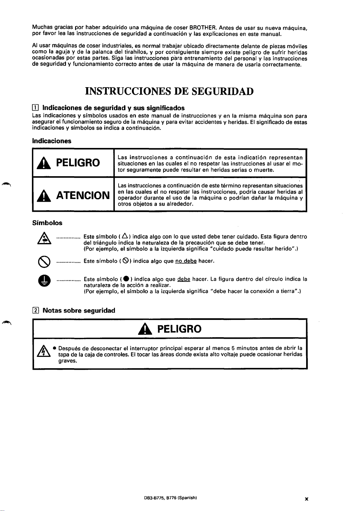
[1)
~
Notas
/A.
sobre seguridad
• Despues de desconectar
tapa de
graves.
Ia
caja de controles.
A PELIGRO
el
interrupter principal esperar
El
tocar
las
areas donde exista alto voltaje puede ocasionar heridas
al
menos 5 minutos antes de abrir
Ia
083-8775, 8776 (Spanishl
X
Page 14
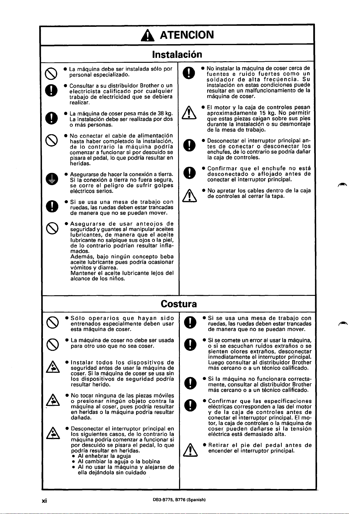
A
ATENCION
lnstalacion
•
• Consultar a
•
0
• No conectar el cable de
• Asegurarse
•
•
0
•
La
maquina debe ser instalada
personal especializado.
su
electricista
trabajo de electricidad que se debiera
realizar.
La
maquina de coser pesa mas de
La
instalaci6n debe ser realizada par dos
0 mas personas.
hasta haber completado
de
lo
comenzar a funcionar si par descuido
pisara
heridas.
contrario
el
Si
Ia
conexi6n a tierra no fuera segura,
se
corre
electricos serios.
Si
se usa una mesa
ruedas,
de manera que no
Asegurarse
seguridad y guantes
lubricantes,
lubricante no salpique sus ojos o
de
lo
contrario
mados.
Ademas, bajo
aceite lubricante pues podria ocasionar
v6mitos
Mantener el aceite lubricante lejos del
alcance de los ninos.
distribuidor Brother o un
calificado
Ia
maquina
pedal, lo que podria resultar
de
hacer
Ia
conexi6n a tierra .
el
peligro
las
ruedas deben estar trancadas
de manera
y diarrea.
se
de
usar
podrian
ningun
de
de
puedan mover.
al
manipular aceites
concepto
s61o
por
cualquier
38
alimentaci6n
Ia
instalaci6n,
podrfa
sufrir
golpes
trabajo
anteojos
que
el aceite
resultar
Ia
infla-
beba
por
kg.
se
en
con
de
piel,
0
0
0
• No instalar
fuentes e ruido
soldador
instalaci6n en estas condiciones puede
resultar
maquina de coser.
•
El
motor y Ia
aproximadamente
que estas piezas caigan sabre sus pies
durante
de
Ia
• Desconectar el interrupter principal antes
enchufes, de lo contrario se pod ria danar
Ia
caja de controles.
•
Confirmar
desconectado o aflojado
conectar el interrupter principal.
• No apretar los cables dentro de
de controles
Ia
maquina de coser cerca de
de
en
un malfuncionamiento de
Ia
instalaci6n o su desmontaje
mesa de trabajo.
de
conectar o desconectar
que
fuertes
alta
frecuencia.
caja de controles pesan
15 kg. No
el
enchufe
al
cerrar
Ia
tapa.
como
permitir
no
antes
Ia
un
Su
los
esta
de
caja
Ia
(9
• S61o
(9
•
•
~
• No tocar ninguna
~
'
• Desconectar el
~
Costura
operarios
entrenados especialmente deben usar
esta maquina de coser.
La
maquina de coser no debe ser usada
para otro usa que no sea coser.
lnstalar
seguridad antes de usar
coser.
los
resultar herido.
o
presionar
maquina al coser, pues podrfa resultar
en
danada.
los siguientes
maquina podrfa comenzar a funcionar si
par descuido
podria resultar
• AI enhebrar
• AI cambiar
• AI no usar
todos
Si
Ia
dispositivos
heridas o
ella dejandola sin cuidado
maquina de coser
que
hayan
los
dispositivos
Ia
maquina de
se
de
seguridad
de
ningun
Ia
se
Ia
Ia
las piezas m6viles
objeto
maquina podria resultar
interruptor
casas, de lo contrario
pisara el pedal, lo que
en
heridas.
Ia
aguja
aguja o
maquina y alejarse de
Ia
usa sin
podria
contra
principal en
bobina
sido
de
Ia
Ia
0
0
0
0
&
• Si se usa
ruedas, las ruedas deben estar trancadas
de manera que no
•
Si
se
o si
sienten
inmediatamente el interrupter principal.
Luego consultar al
mas cercano o a un tecnico calificado.
• Si
Ia
mente, consultar al distribuidor Brother
mas cercano o a un tecnico calificado.
•
Confirmar
electricas corresponden a las del motor
y de
conectar
tor,
Ia
coser
electrica esta demasiado alta.
•
Retirar
encender el interrupter principal.
una
mesa
de
trabajo
se
puedan mover.
comete un error
se
escuchan ruidos extranos o
olores
maquina no funcionara correcta-
que
Ia
caja
el
interruptor principal.
caja de controles o
pueden
el
pie
al
usar
extralios,
distribuidor
las
especificaciones
de
controles
daliarse
del
pedal
Ia
maquina,
desconectar
Brother
antes
Ia
si Ia
El
maquina
tensi6n
antes
con
se
de
mo-
de
de
xi
083-8775, 8776 (Spanish)
Page 15
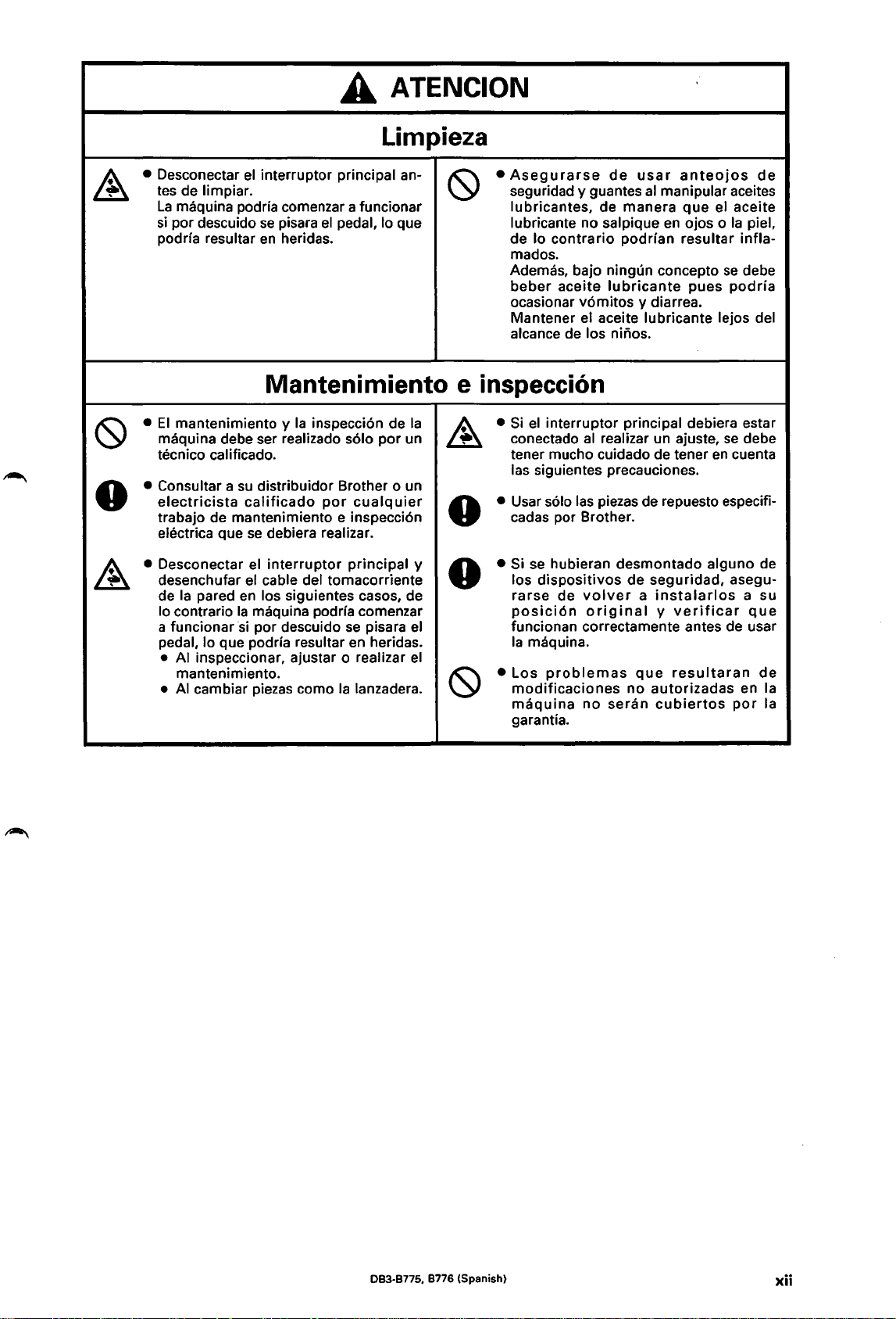
A
ATENCION
Limpieza
• Desconectar el interrupter principal antes de limpiar.
La
maquina podria comenzar a funcionar
si
por descuido
resultar
podria
se
pisara
en
heridas.
el
pedal, lo que
Mantenimiento e inspecci6n
•
El
mantenimiento y
maquina debe ser realizado
tecnico
• Consultar
electricista
trabajo de mantenimiento e inspecci6n
electrica que
Desconectar el
•
desenchufar el cable del tomacorriente
de
lo contrario
a funcionar
pedal, lo
•
•
calificado.
a
su
calificado
se
Ia
pared
en
Ia
si
que podria resultar en heridas.
AI
inspeccionar, ajustar o realizar
mantenimiento.
AI
cambiar piezas como
Ia
inspecci6n de
s61o
por un
distribuidor Brother o un
por
cualq
uier
debiera realizar.
interrupter
los siguientes casos, de
maquina pod ria comenzar
por descuido
principal y
se
pisara el
Ia
lanzadera.
Ia
el
•
Asegurarse
seguridad y guantes
lubricantes, de manera
lubricante no salpique
de lo
contrario
mados.
Ademas, bajo ningun concepto
beber
ocasionar v6mitos y diarrea.
Mantener
alcance
Si
•
conectado
tener mucho cuidado de tener
las siguientes precauciones.
• Usar solo
cadas por Brother.
• Si
los dispositivos
rarse
posici6n
funcionan correctamente antes de usar
Ia
• Los
modificaciones
maquina
garantia.
aceite
el
interrupter principal debiera estar
se
hubieran desmontado alguno de
de
maquina.
problemas
de
usar
anteojos
al
manipular aceites
que
el aceite
en
ojos o
Ia
podrian resultar infla-
se
lubricante
el aceite lubricante lejos del
de los ninos.
al
realizar un ajuste,
las
piezas de repuesto especifi-
de
volver a instalarlos
original y verificar
que
no
no
seran
pues
podria
se
en
cuenta
seguridad, asegu-
resultaran
autorizadas en
cubiertos
por
de
piel,
debe
debe
a su
que
de
Ia
Ia
083-8775, 8776 (Spanish)
xii
Page 16
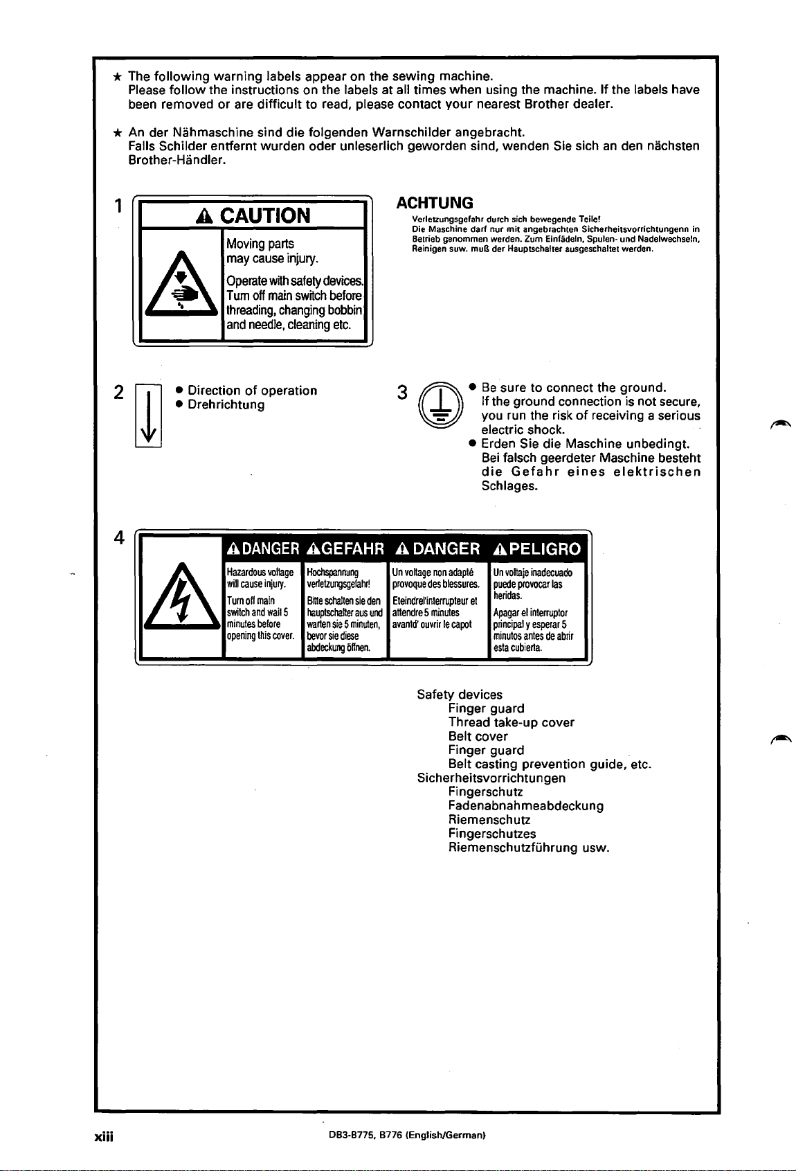
* The
following
follow
Please
been removed
warning labels appear on the sewing machine.
the instructions on the labels at all times when using the machine.
or
are
difficult
to read, please contact
your
nearest Brother dealer.
* An der Nahmaschine sind die folgenden Warnschilder angebracht.
Falls Schilder entfernt wurden oder unleserlich geworden sind, wenden Sie sich
Brother-Handler.
If
the labels have
an
den nachsten
1
A
4
A CAUTION
Moving
may
cause
Operate
Tum
off
threading,
and
needle,
• Direction
Drehrichtung
•
of
operation
A
DANGER
Hazardous
will
cause
Turnoff
main
switch
and
minutes
before
opening
this
parts
injury.
with
main
changing
cleaning
voltage
injury.
wait
5
cover.
ACHTUNG
Verletzungsgefahr durch sich bewegende Teile!
Die Maschino
Betrieb genommen werden.
Reinigen suw.
safety
devices.
switch
before
bobbin
etc.
3
G)
AGEFAHR A DANGER
Hochspannung
verietzungsgefaM
Bitte
schalten
hauptschatter
warten
sie 5 minuten,
bevor
sie
diese
abdeckW1Q
iiffnen.
Un
provoque
sie
den
Eteindrerinterrupteur
aus
und
attendre 5 minutes
avantd'
voltage
des
ouvrir
non
darf
nur
mit
angebrachten Sicherheitsvorrichtungenn in
muB der Hauptschalter ausgeschaltet werdon.
•
Be
If
you run the risk
electric shock.
• Erden Sie die Maschine unbedingt.
Bei
die
Schlages.
Zum Einfadeln, Spulen- und Nadelwechseln,
sure
to
the ground connection is not secure,
falsch geerdeter Maschine besteht
connect the ground.
of
Gefahr
eines
receiving a serious
elektrischen
APELIGRO
adapte
blessures.
le
capo!
Un
voltaie
puede
heridas.
et
Apagar
principal y esperar
minutos
esta
cubierta.
inadecuado
provocar
el
interrupter
antes
de
las
5
abrir
·
Safety devices
Finger guard
Thread take-up cover
Belt cover
Finger guard
Belt casting prevention guide, etc.
Sicherheitsvorrichtungen
Fingerschutz
Fadenabnahmeabdeckung
Riemenschutz
Fingerschutzes
Riemenschutztuhrung usw.
xiii
083-8775, 8776 (English/German)
Page 17
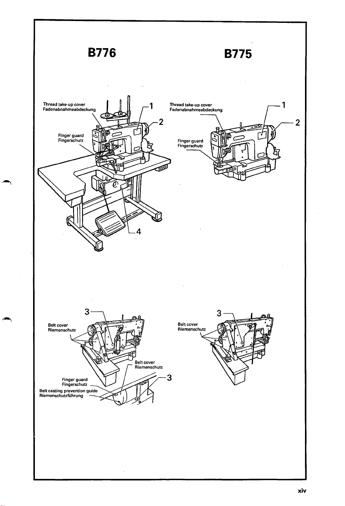
8776
Thread take-up cover
Fadenabnahnneabdeckung
8775
2
Belt cover
Riennenschutz
Belt cover
Riennenschutz
3
xiv
Page 18
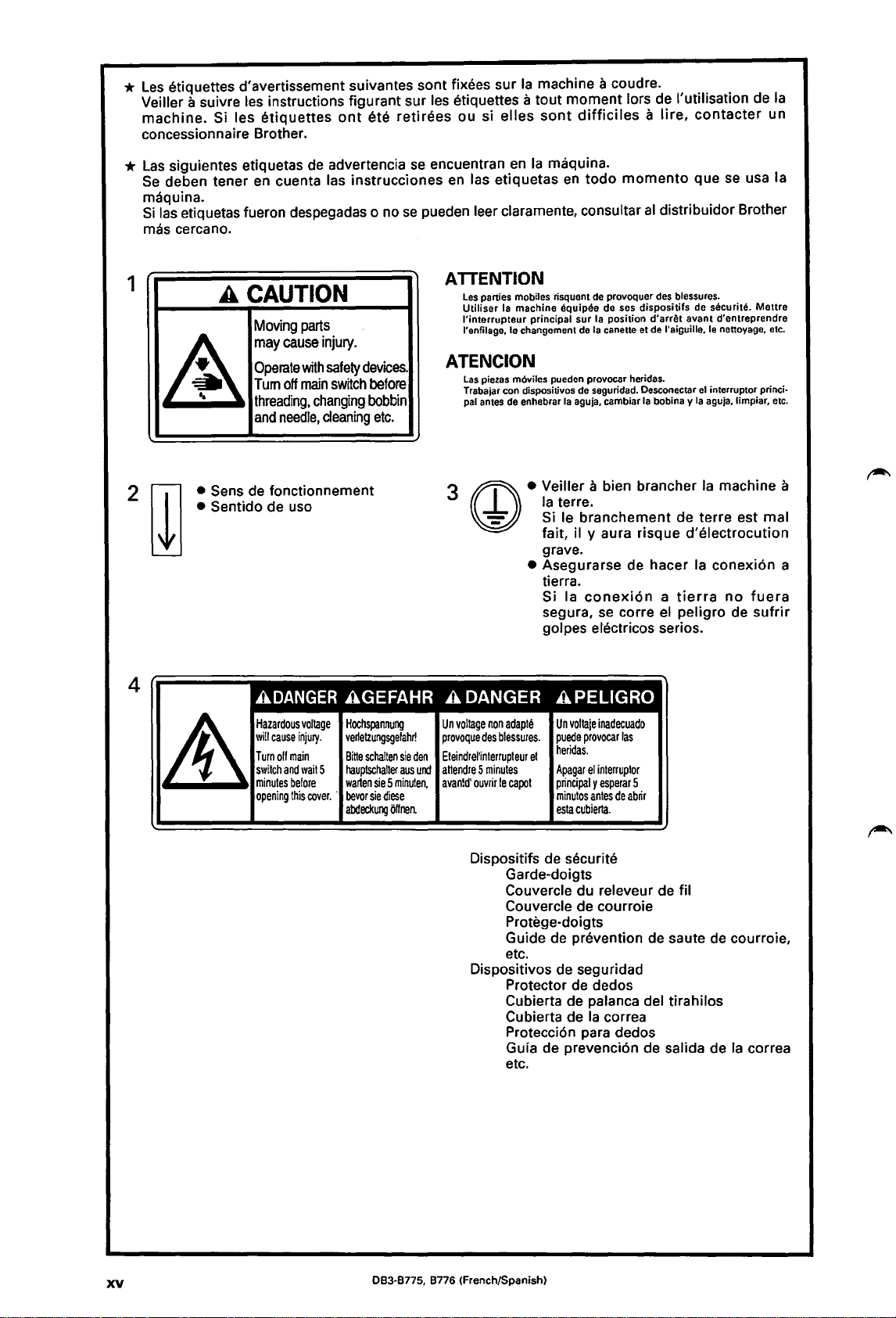
*
Les
etiquettes d'avertissement suivantes sont fixees sur
Veiller a suivre les instructions figurant sur les etiquettes a
machine.
concessionnaire Brother.
*
Las
Se
deben tener en cuenta las instrucciones en las etiquetas
maquina.
Si
las etiquetas fueron despegadas o
mas cercano.
Si les
siguientes etiquetas de advertencia
etiquettes
ont
ete
nose
retirees
se
ou si
encuentran
pueden leer claramente, consultar
Ia
machine a coudre.
tout
moment
elles
sont
en
Ia
maquina.
en
lors de !'utilisation de
difficiles a lire,
todo
momento
al
distribuidor Brother
Ia
contacter
que se usa Ia
un
1
A CAUTION
~
• Sens de fonctionnement
• Sentido de uso
4
Moving
parts
may
cause
injury.
Operate
Tum
threading.
and
with
off
main
changing
needle,
safety
cleaning
ADANGER
Hazardous
cause
switch
and
minutes
opening
voltage
injury.
main
waitS
before
this
cover.
will
Turnoff
ATTENTION
Les
parties mobiles risquont de provoquer des blessures.
Utiliser
Ia machine equipee de ses
l'interrupteur
l'enfilage, le changement de
devices.
switch
before
bobbin
etc.
AGEFAHR A DANGER
Hochspannung
vertetzungsgelahr!
Bit1e
schalten
haup1schalter
warten
sie 5 minulen,
·
bevor
sie
diese
abdeckung
Offnen.
ATENCION
3
Un
voltage
provoque
sie
den
Eteindrel'interrupteur
aus
und
aHendre 5 minutes
avantd'
Las
piezas m6viles puedon provocar heridas.
Trabajar con dispositivos de seguridad. Desconectar
pal
antes de enhebrar
G)
non
adapte
des
blessures.
ouvrir
le
principal sur Ia position
Ia
aguja, cambiar
dispositifs
Ia
canette et de l'aiguille, le nettoyage, etc.
Ia
• Veiller a bien brancher
Ia
terre.
Si le branchement de terre est mal
fait, il y aura risque d'electrocution
grave.
• Asegurarse de hacer
tierra.
Si Ia
conexi6n a tierra
segura,
golpes electricos serios.
se
corre el peligro de
d'arret
bobina y
de securite.
avant
el
interruptor princi·
Ia
aguja, limpiar, etc.
Ia
Ia
conexi6n a
APELIGRO
Un
voltaje
inadecuado
puede
provocar
et
capot
heridas.
Apagar
principal y esperar
minutos
esta
el
interruptor
antes
cubierta.
de
las
5
abrir
Mettre
d'entreprendre
machine a
no
fuera
sufrir
Dispositifs de securite
Garde-doigts
Couvercle du releveur de fil
Couvercle de courroie
Protege-doigts
Guide de prevention de saute
etc.
Dispositivos de seguridad
Protector de dedos
Cubierta de palanca del tirahilos
Cubierta de
Protecci6n para dedos
Guia de prevenci6n de salida de
etc.
XV
083-8775, 8776 (French/Spanish)
Ia
correa
de
courroie,
Ia
correa
Page 19
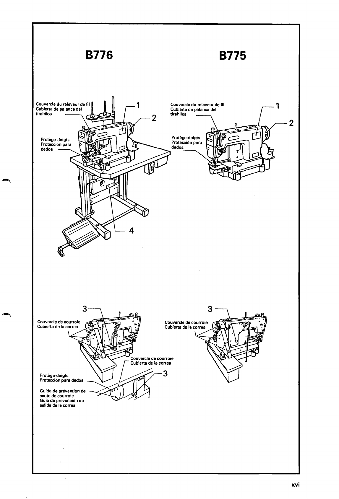
8776
8775
Couvercle du releveur de fil
Cubierta de palanca del
tirahilos
4
2
Couvercle
Cubierta de palanca del
tirahilos
du
releveur de fil
2
Protege-doigts
Protecci6n para dedos
Guide de prevention de
saute de courroie
de
prevenci6n de
Guia
salida de
Ia
correa
xvi
Page 20
CONTENTS
1.
NAMES
OF
MAJOR
PARTS.................... 1
2. MACHINE SPECIFICATIONS ................... 2
3. WORK TABLE
3-1. Work Table ............................................ 3
Installing the
3-2.
table (8776) ........................................... 4
3-3.
Motor
AND
MOTOR .................... 3
motor
to the work
(8775) ......................................... 5
4. INSTALLATION ......................................... 7
4-1. Installing the machine head ............... 8
Installing the belt cover....................... 9
4-2.
Installing the belt .................................
4-3.
4-4. Installing the bobbin winder ...............
4-5. Installing the presser lifter pedal
(8775) ....................................................
4-6. Connecting the cords (8776) .............. 14
air
4-7. Connecting the
4-8. Adjusting the air pressure (8776) ......
4-9. Installing the cotton stand ..................
4-10. Lubrication ............................................
4-11. Checking the machine pulley
rotating direction ..................................
4-12. Installing the head lamp (8776) .........
tubes (8776) .........
5. PREPARATION BEFORE SEWING ...........
5-1. Removing the bobbin
5·2. Winding the lower thread ................... 24
5-3. Threading the
5-4. Installing the needle ............................ 26
5-5. Threading the upper thread ................
5-6.
Adjusting the stitch length ..................
lower
6. SEWING (B776) ............................................ 30
6-1.
Using the control box ..........................
6-2. Operating the treadle ...........................
6-3.
Sewing ..................................................
case
.................
thread ................
11
13
13
17
18
19
19
20
21
23
23
25
27
28
31
32
38
7. THREAD TENSION .......................................
7-1. Adjusting the thread tension ..............
7-2. Adjusting the presser
7-3. Adjusting the feed roller pressure .....
foot
pressure
8. CLEANING .................................................
9. STANDARD ADJUSTMENTS ...................
9-1. Adjusting the thread tension
spring .................................................... 46
9-2. Adjusting arm thread guide R ............ 48
foot
9-3. Adjusting the presser
9-4. Adjusting the needle bar height .........
9-5. Adjusting the needle and rotary
timing
hook
9-6. Adjusting the thread
9-7. Thread
9-8. Adjusting the tension release lever
position (8776) .....................................
9-9. Adjusting the upper shaft and
rotary hook
9-10. Synchronizer adjustment (8776) ........
9-11. Replacing the knives (8776) ................ 64
9-12. Adjusting the
9-13. Setting the
9-14. Adjusting the knife position (8776) ....
...........................................
trimmer
cam
lubrication amount .........
treadle (8776) ...............
DIP
switches (8776) .........
10.1NSTALLING OPTIONAL PARTS
(B776) ......................................................... 77
10-1. Installing the knee switch ...................
10-2. Installing the air
10-3. Connecting the pedal
operations .............................................
blow
11.TROUBLESHOOTING .................................
height ......
wiper
(8776) .....
timing
(8776) ...
device .............
for
standing
39
39
..
41
41
42
44
49
51
52
56
57
61
62
63
65
67
73
77
85
89
92
083-8775, 8776 (English)
Page 21
INHALT
1.
HAUPTTEILE .............................................. 1
2. TECHNISCHE DATEN............................... 2
3. NAHTISCH
3-1. Nahtisch ................................................ 3
3-2. Montage des Motors am Nahtisch
3-3.
4. MONTAGE ................................................. 7
4-1. Montage des Maschinenoberteils ...... 8
4-2. Montage des Riemenschutzes ............ 9
4-3. Riemenmontage ...................................
4-4. Montage des Spulers ...........................
4-5. Montage des StoffdruckerfuBpedals
4-6.
4-7. AnschlieBen Der Druckluftleitungen
4-8. Einstellen des Luftdrucks (8776) ........
4-9. Montage des Spulentragers ................
4-10. Schmierung ..........................................
4-11. Kontrolle der Nahmaschinen-
4-12. Montage der Leuchte (8776) ..............
5. VOR8EREITUNGEN
5-1. Herausnehmen der Spulenkapsel ......
5-2.
5·3. Einfadeln des Unterfadens ..................
5-4.
5-5.
5-6. Einstellen der Stichlange .....................
6. HAHEN (8776) ··············································
6-1.
6-2.
6-3.
UND
MOTOR........................ 3
(8776) .................................................... 4
Motor
(8775) ......................................... 5
11
13
(8775) ....................................................
AnschluB der Kabel (8776) ................. 14
(8776) .....................................................
Riemenscheibendrehrichtung .............
ZUM
NAHEN ........
Aufwickeln des Unterfadens ...............
Einsetzen der Nadel .............................
Einfadeln des Oberfadens ...................
Schaltkasten ..........................................
8edienung des Pedals .........................
Hahen ....................................................
13
17
18
19
19
20
21
23
23
24
25
26
27
28
30
31
33
38
7. FADENSPANNUNG ..................................
7-1.
Einstellen der Fadenspannung ...........
7-2.
Einstellen des StoffdruckerfuB-
drucks ....................................................
7-3.
Einstellen des Vorschubrollendrucks
8. REINIGUNG ...............................................
...
39
39
41
41
42
9. STANDARDEINSTELLUNGEN .................. 44
9-1.
Einstellen der Fadenspannungs-
feder ...................................................... 46
Einstellen der Armfadenfuhrung R
9-2.
Einstellen der StoffdruckerfuBhOhe
9-3.
9-4. Einstellen der Nadelstangenhohe ......
9·5. Einstellen der Nadei-
Greifersynchronisierung ......................
9·6. Einstellen des Fadenwischers
(8776) ....................................................
9-7. Nockensynchronisation des
Fadenabschneiders (8776) ..................
9-8. Einstellen des Spannungs-
verminderungshebels (8776) ..............
9-9.
Einstellen der Schmierung der
oberen
9-10. Einstellen des Synchronisators
(8776) ....................................................
9-11. Ersetzen der Messer (8776) ................ 64
9-12. Einstellen des Pedals (8776) ...............
9-13. Einstellen der DIP-Schalter (8776) .....
9-14. Einstellen der Messerposition
(8776) ···················································· 74
10.AN8RINGEN
Welle und des Drehgreifers
VON
ZUBEHORTEILEN
(8776) .......................................................
10-1.
Einbau des Knieschalters ....................
10-2. Einbau der Druckluftvorrichtung ........ 86
10-3. AnschlieBen des Pedals
stehenden 8etrieb ................................
fur
11.FEHLERSUCHE ........................................ 96
...•
...
...
48
49
51
53
56
58
61
62
63
66
67
79
79
89
DB3·B775, 8776 (German)
Page 22
TABLE
DES
MATIERES
1.
NOM
DES PIECES PRINCIPALES ........... 1
2. SPECIFICATIONS DE
LA
MACHINE ...... 2
3. TABLE DE TRAVAIL ET MOTEUR.......... 3
3-1.
Table de travail ..................................... 3
Installation du moteur sur
3-2.
de travail (8776) ................................... 4
3-3. Moteur (8775) ....................................... 5
Ia
table
4. INSTALLATION ...... :.................................. 7
4-1. Installation de
Installation du couvercle de
4-2.
courroie ................................................. 9
Installation de
4-3.
4-4. Installation du bobineur de canette .....
4-5. Installation de
presseur (8775) ....................................
4-6. 8ranchement des cordons (8776) ...... 14
4-7.
Raccordement des tubes a
(8776) ....................................................
4-8.
Reglage de
4-9.
Installation de
bobine ...................................................
4-10. Lubrification ..........................................
4-11.
Verification du sens de rotation de
Ia
poulie de machine ...........................
4-12.
Installation de !'ampoule de tete de
machine (8776) .....................................
5.
PREPARATIFS AVANT
5-1.
Retrait de
5-2.
8obinage du fil inferieur ..................... 24
5-3.
Enfilage du fil inferieur ........................
5-4.
Installation de l'aiguille .......................
5-5.
Enfilage du fil superieur ......................
5-6.
Reglage de
6. COUTURE (8776) ..........................................
6-1.
Utilisation du boitier
6-2.
Fonctionnement de
6-3.
Couture .................................................. 38
Ia
tete
de
machine...... 8
Ia
courroie ...................
Ia
pedale du
Ia
pression d'air (8776)
Ia
broche porte-
LA
Ia
boite a canette ................
Ia
longeur de point ..........
de
Ia
rel~ve-
air
COUTURE....
commande ....
pedale ............. 34
...
11
13
13
17
18
19
19
20
21
23
23
25
26
27
29
30
31
7. TENSION DU FIL ......................................
7-1. Reglage de
7-2. Reglage de
presseur ................................................
7-3. Reglage de
rouleau d'entrainement .......................
8.
NETTOVAGE ..............................................
9. REGLAGES STANDARD
9-1. Reglage du ressort de tension du fil
9-2. Reglage du guide-fil D du bras .......... 48
Reglage de
9-3.
presseur ................................................
9-4. Reglage de
aiguille ...................................................
9-5. Reglage de
l'aiguille et du crochet rotatif .............
9-6. Reglage du tire-fils (8776) ...................
9-7.
Synchronisation de
coupe-fils (8776) ...................................
9-8. Reglage de
liberation de tension (8776) ................
9-9. Reglage de
de l'arbre superieur
rotatif .....................................................
9-10. Reglage du synchroniseur (8776) ......
9-11. Remplacement des couteaux
(8776) ....................................................
9-12. Reglage de
9-13. Reglage des interrupteurs
(8776) ....................................................
9-14. Reglage de
(8776) ....................................................
Ia
tension du fil ................
Ia
pression du pied
Ia
pression du
.............................
Ia
hauteur du pied
Ia
hauteur de
Ia
synchronisation de
Ia
position du levier de
Ia
quantite de lubrification
Ia
pedale
Ia
position du couteau
Ia
Ia
came de
et
du crochet
(87761
barre a
...............
DIP
10.1NSTALLATION DES PIECES EN
OPTION (8776) ..........................................
10-1. Installation de l'interrupteur
genou ....................................................
10-2. Installation de
10-3. 8ranchement de
!'utilisation debout ...............................
Ia
soufflerie
Ia
pedale pour
au
d'air
.........
11.RESOLUTION DES PROBLEMES ..........
...
39
39
41
41
42
45
47
50
51
54
56
59
61
62
63
64
66
68
75
81
81
87
90
100
083-8775, 8776 (French I
Page 23
CONTENIDO
1. NOM8RES
DE
LAS PIEZAS
PRINCIPALES ............................................ .
2. ESPECIACACIONES
3.
MESA
3-1. Mesa de trabajo ................................... 3
3-2.
3-3.
DE
TRA8AJO V MOTOR............. 3
lnstalaci6n del
trabajo (8776) ....................................... 4
Motor
(8775) ......................................... 5
DE
motor
LA
MAQUINA.. 2
en
Ia
mesa de
4. INSTALACION ........................................... 7
4-1. lnstalaci6n de
maquina ................................................ 8
lnstalaci6n de
4-2.
correa .................................................... 9
4-3.
lnstalaci6n de
4-4. lnstalaci6n de
4-5. lnstalaci6n del pedal levantador
del prensatelas (8775) .........................
4-6. Conexi6n de los cables (8776) ...........
4-7. Conexi6n de
(8776) ....................................................
4-8. Ajuste de
4-9. lnstalacion del
4-10. Lubricaci6n ...........................................
4-11. Verificaci6n de
rotaci6n de
lnstalaci6n de
4-12.
5.
PREPARATIVOS ANTES
5-1.
Manera de sacar
bobina ...................................................
5-2.
8obinado del hilo inferior ...................
5-3.
Enhebrado del hilo inferior .................
5-4.
Colocacion de
5-5.
Enhebrado del hilo superior ...............
5-6.
Ajuste del largo de puntada ...............
6. COSTURA (8776)
6-1. Uso de
6-2. Uso del pedal .......................................
6-3. Costura ..................................................
Ia
cabeza
Ia
cubierta
Ia
correa .......................
Ia
bobinadora ..............
Ia
tuberia de aire
Ia
presion de aire (8776) ....
so
porte del carrete .....
Ia
Ia
polea de
Ia
luz (8776) .................
Ia
Ia
aguja ........................
de
Ia
de
direcci6n de
Ia
maquina ...
DE
COSER ......
caja de
Ia
Ia
..........................................
Ia
caja de controles ................
11
13
13
14
17
18
19
19
20
21
23
23
24
25
26
27
29
30
31
35
38
7. TENSION DEL HILO .................................
7-1. Ajuste
7-2. Ajuste
prensatelas
7-3. Ajuste de
de alimentaci6n ....................................
de
Ia
tensi6n del hilo ...............
de
Ia
presi6n del
................................ ; ...........
Ia
presion del rodillo
8. LIMPIEZA ...................................................
9. AJUSTES ESTANDARES
9-1. Ajuste del resorte del tirahilos ...........
9-2.
Ajuste del guiahilos R del brazo ........
9-3.
Ajuste de
9-4.
Ajuste de
aguja ......................................................
9-5.
Ajuste de sincronizacion de
y
Ia
9-6.
Ajuste del limpiador de hilos
(8776) ....................................................
9-7. Sincronizaci6n de
cortahilos (8776) ..................................
9-8. Ajuste de
de liberaci6n de tension (8776) ..........
9-9. Ajuste de
superior
9-10. Ajuste del sincronizador (8776) ..........
9-11. Cambio de las cuchillas (8776) ..........
9-12. Ajuste del pedal (8776) ....................... 66
9-13. Ajuste
(8776) ....................................................
9-14. Ajuste de
(8776) .................................................... 76
10.1NSTALACION
Ia
altura del prensatelas ....
Ia
altura
lanzadera .......................................
Ia
posicion de
Ia
lubricaci6n del eje
y
Ia
lanzadera ........................
de
los interruptores
Ia
posicion de
DE
OPCIONALES (8776) ................................
10-1.
lnstalaci6n del interruptor de
rodilla .................................................... 83
10-2.
lnstalaci6n del dispositivo soplador
de aire ................................................... 88
10-3.
Conexi6n del pedal para trabajar
parado ...................................................
11.LOCALIZACION
DE
............................
de
Ia
barra de
Ia
aguja
Ia
leva del
Ia
palanca
DIP
Ia
cuchilla
PIEZAS
AVERIAS ................ 104
39
39
41
41
42
45
47
48
50
51
55
56
60
61
62
63
65
68
83
90
083-8775, 8776 (Spanish)
Page 24
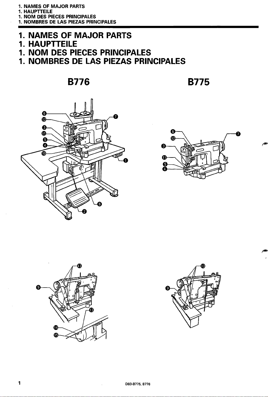
1.
NAMES
1. HAUPTTEILE
1.
NOM
1. NOMBRES
1.
NAMES
1.
HAUPTTEILE
1.
NOM
1.
NOMBRES
OF
MAJOR
DES PIECES PRINCIPALES
DE
DES
PARTS
LAS PIEZAS PRINCIPALES
OF
MAJOR
PIECES
DE
LAS PIEZAS PRINCIPALES
PARTS
PRINCIPALES
8776
8775
1
083·8775,
8776
Page 25
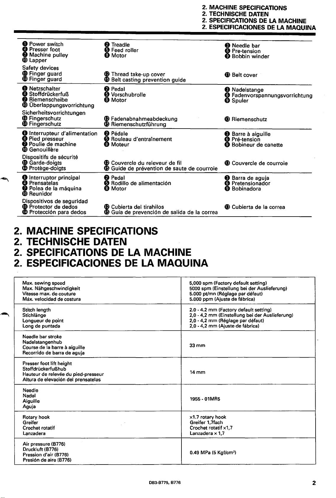
2. MACHINE SPECIFICATIONS
2. TECHNISCHE DATEN
SPECIFICATIONS DE
2.
2. ESPECIFICACIONES DE LA
LA
MACHINE
MAQUINA
0 Power switch
8 Presser foot
f)
Machine pulley
~
Lapper
Safety devices
CD
Finger guard
e Finger guard
0 Netzschalter
8 StoffdruckerfuB
f)
Riemenscheibe
~
Oberlappungsvorrichtung
Sicherheitsvorrichtungen
CD
Fingerschutz
e Fingerschutz
0 lnterrupteur d'alimentation
8 Pied presseur
f)
Poulie de machine
~
Genouillere
Dispositifs de securite
CD
Garde-doigts
e Protege-doigts
0 lnterruptor principal
8 Prensatelas
f)
Polea de
~
Reunidor
Dispositivos de seguridad
CD
Protector de dedos
Ia
maquina
e Protecci6n para dedos
8 Treadle
0
Feed
roller
0 Motor
tB
Thread take-up cover
~
Belt casting prevention guide
8
Pedal
0 Vorschubrolle
0 Motor
tB
Fadenabnahmeabdeckung
~
Riemenschutzfuhrung
8 Pedale
0 Rouleau d'entrainement
0 Moteur
tB
Couvercle du releveur de fil
~Guide
I
tB
~
de prevention de saute de courroie
Pedal
Rodillo de alimentaci6n
Motor
Cubierta del tirahilos
Guia de prevenci6n de salida de
Ia
correa
8 Needle bar
0 Pre-tension
0 Bobbin winder
..
Belt cover
8 Nadelstange
0 Fadenvorspannungsvorrichtung
0 Spuler
..
Riemenschutz
Barre a aiguille
Pre-tension
Bobineur de canette
I
• Couvercle de courroie
Barra de aguja
Pretensionador
Bobinadora
I
• Cubierta de
Ia
correa
2. MACHINE SPECIFICATIONS
2. TECHNISCHE DATEN
SPECIFICATIONS
2.
2. ESPECIFICACIONES
Max. sewing speed 5,000 spm (Factory default setting)
Max. Nahgeschwindigkeit
Vitesse max. de couture 5.000 pt/mn (Reglage par defaut)
Max. velocidad
Stitch length
Stichlange
Longueur de point
Long de puntada
Needle bar stroke
Nadelstangenhub
Course
de
Recorrido de barra de aguja
Presser
foot
StoffdruckerfuBhub
Hauteur de relevee du pied-presseur
Altura de elevaci6n del prensatelas
Needle
Nadel
Aiguille
Aguja
de costura
Ia
barre a aiguille
lift
height
DE
LA MACHINE
DE
LA
MAQUINA
5000 spm (Einstellung bei der Auslieferung)
5.000 ppm (Ajuste de fabrica)
2.0-
4.2
2,0-
4,2
2,0 - 4,2
2,0 - 4,2
33mm
14mm
1955-01MR5
mm
(Factory default setting)
mm
(Einstellung bei der Auslieferung)
mm
(Reglage par defaut)
mm
(Ajuste
de
fabrica)
Rotary hook
Greifer
Crochet rotatif Crochet rotatif x1, 7
lanzadera
Air pressure (8776)
Druckluft (8776)
Pression d'air (8776)
Presion de aire (8776)
DB3-B775, B776
x1.7 rotary hook
Greifer 1,7fach
lanzadera x
0.49 MPa
(5
1,7
Kgf/cm
2
)
2
Page 26
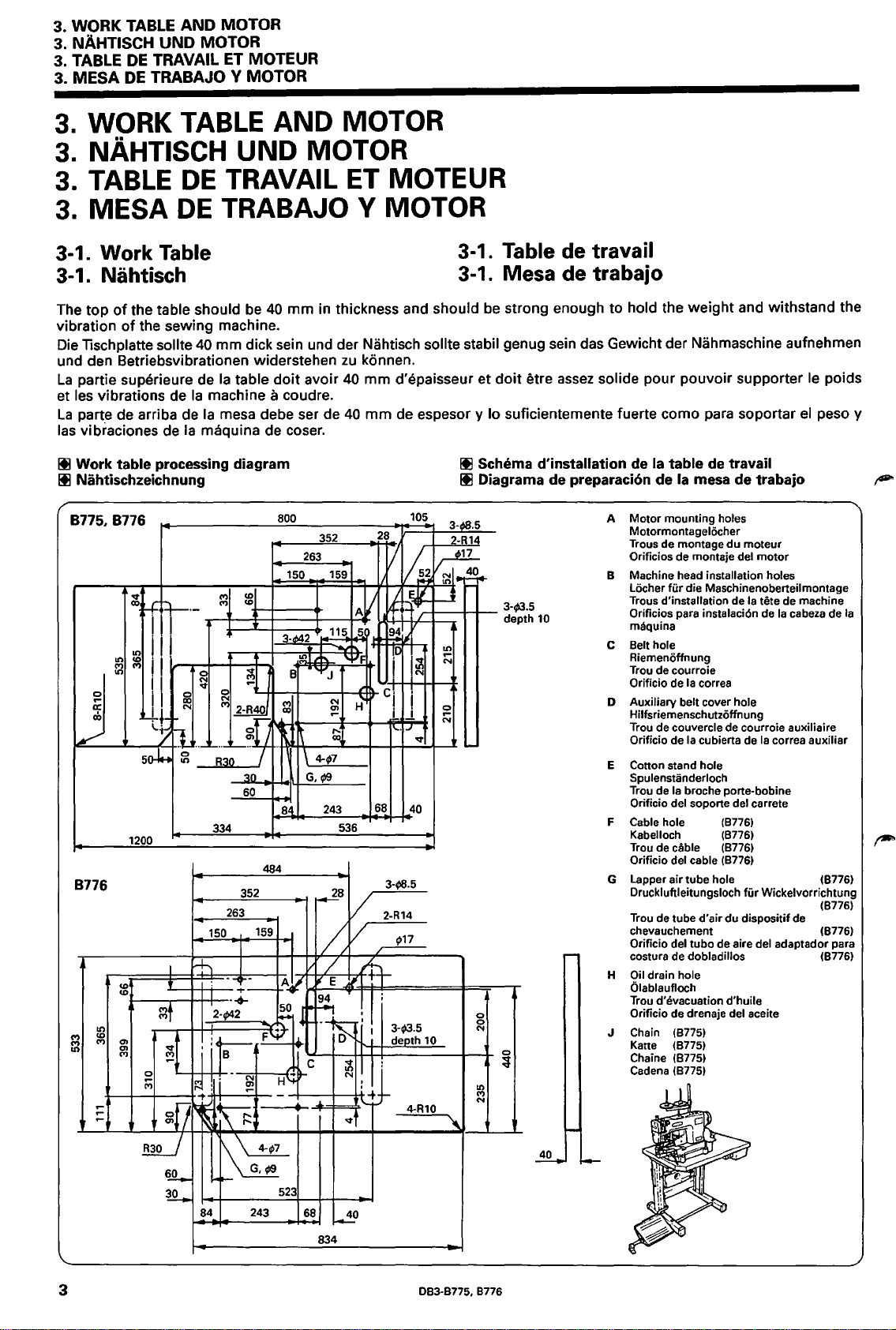
3. WORK TABLE
3. NAHTISCH UNO MOTOR
3. TABLE
MESA
3.
3.
3.
DE
DE
WORK TABLE AND MOTOR
NAHTISCH UNO MOTOR
AND
MOTOR
TRAVAIL
TRABAJO V MOTOR
ET
MOTEUR
3. TABLE
3.
MESA
3-1. Work Table
3-1. Nahtisch
The top
vibration
Die
und den Betriebsvibrationen widerstehen
La
et
La
las
It! Work table processing diagram
ltl Nahtischzeichnung
of
the table should be
of
lischplatte sollte
partie superieure de
les vibrations de
parte de arriba de
vibraciones de
8775,8776
~
0
a:
cO
1-=/=---...L...-'-~~-++
1200
8776
"'
"'
It)
M
"'
"'
M
"'
....
....
....
DE
TRAVAIL
DE
TRABAJO V MOTOR
40
the sewing machine.
40
mm dick sein und der Nahtisch sollte stabil genug sein das Gewicht der Nahmaschine aufnehmen
Ia
table
Ia
machine a coudre.
Ia
mesa debe ser de
Ia
maquina de coser.
r,....
.,,.,
~
·-
:81
...--+----'_tF-1----+--+'+
4
I I
j I t
II
lJ
so-l..
0
....
M
~
~
~ v ~
g
I
f
~t
~t
gfl
tm_
~
kfi:=~40
,_._
..
"---~
R3o
~n
60
334
352
263
150
tl
--< -
:
...
.....
2-942
j
its
-
I~
:li
-t
,....
,....
~
~~
~
~
84
~l
484
159
-
F~
N
....
"'
--+-
f3
243
ET
MOTEUR
3-1.
Table de travail
3-1. Mesa de trabajo
mm
in thickness and should be strong enough to hold the weight and withstand the
zu
konnen.
doit
avoir
40
mm
40
d'epaisseur et
mm
de espesor y lo suficientemente fuerte como para soportar
doit
etre
assez
It! Schema d'installation de Ia table de travail
It! Diagrama de preparacion de
1/1
I/
I ~ t
~
•
~
~
1!1:
I
C· ,
! I
!..,
1'-·IJ
1
68
H8.5
2-R14
~17
1 3-;3.5
105
3-08.5
2-R
14
1
!~
1
/
~
~j.,!_O._
3-;3.5
depth
It)
...
N
I~
~
I
N
v
40
0
0
10
4-RlO
N
0
3
It)
M
N
10
800
,._
_ __,3""52"---++-28f+ll
263
150
159
A.ill.rffm,'''ct:':::;tl
H42
&l
115
.5.!
~·~<tei.L~h.~w"F~
B •
"'J
§!
H
H~~·~---~"L-4-1-1-....;.:....._...x
\~4-~97:....__
G.
f3
243
84
536
~8
v
v
/
/
E
A
!I
50
~
H~lt-
-
A
~4
! I :
~
D depth
c
~l~~
v
'
523
68
~0
834
solide pour pouvoir supporter le poids
el
peso y
Ia
mesa de trabajo
A Motor mounting
Motormontagelocher
Trous de montage
Orificios de montaje
8 Machine head installation holes
Locher
fiir
d'installation de
Trous
Oriflcios para instalaci6n de
maquina
C Belt hole
Riemenoffnung
Trou de courroie
Orificio de
D Auxiliary belt cover hole
Hilfsriemenschutzoffnung
Trou de couvercle de courroie auxiliaire
Orificio de
E Cotton stand hole
Spulenstanderloch
Trou de
Orificio del soporte del carrete
Cable hole (8776)
F
Kabelloch (8776)
Trou de
Orificio del cable
G Lapper air tube hole
Druckluftleitungsloch
Trou de tube d'air du dispositif de
chevauchement (8776)
Orificio del tuba de aire del adaptador para
costura de
Oil drain hole
H
Olablaufloch
Trou d'evacuation d'huile
Orificio de drenaje del aceite
J Chain (8775)
Kane (8775)
Chaine
Cadena (8775)
holes
du
moteur
del
motor
die Maschinenoberteilmontage
Ia
correa
Ia
cubierta de
Ia
broche porte-bobine
cable (8776)
dobladillos (8776)
(87751
Ia
tete de machine
Ia
(87761
fiir
Wickelvorrichtung
Ia
cabeza de
correa auxiliar
Ia
(87761
(8776)
3
083-8775, 8776
Page 27
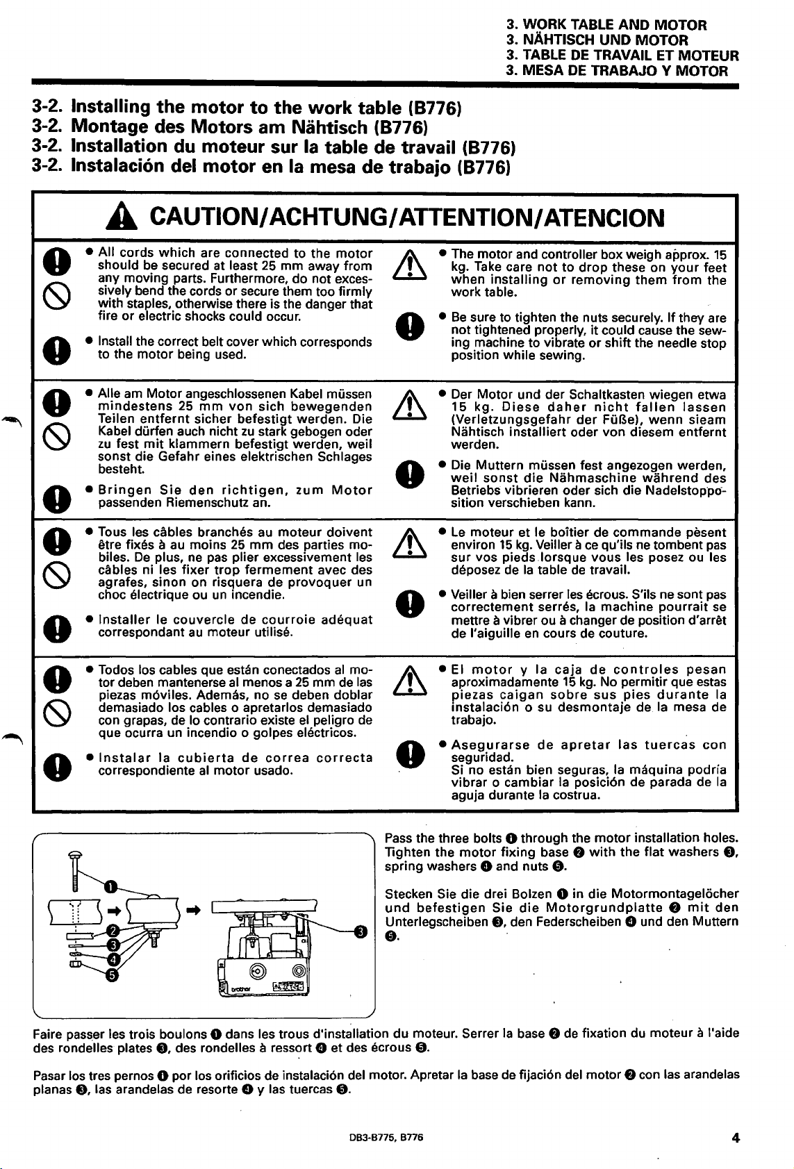
3-2. Installing the motor to the work table (8776)
3-2. Montage des Motors am Nahtisch (8776)
3-2.
Installation
3-2.
lnstalacion del motor
du
moteur
sur
en
Ia
table de travail (8776)
Ia
mesa de trabajo (8776)
3. WORK
3. NAHTISCH
3.
TABLE
3. MESA
TABLE
DE
DE
AND MOTOR
UNO
MOTOR
TRAVAIL ET MOTEUR
TRABAJO V MOTOR
~
0
0
(9
0
0
(9
0
£
• All cords which are connected to the
should be secured at least
any moving parts. Furthermore, do not excessively bend the cords or secure them too firmly
with staples, otherwise there is the danger that
fire
• Install the correct belt cover which corresponds
to the motor being used.
• Aile
mindestens
Teilen
Kabel durfen auch nicht
zu
sonst die Gefahr eines elektrischen
besteht.
•
Bringen
passenden Riemenschutz an.
• Taus les cables branches
etre fixes a
biles.
cables ni les fixer
agrafes, sinon on risquera de provoquer un
choc electrique ou
•
Installer
correspondant
CAUTION/
or
electric shocks could occur.
am
Motor angeschlossenen Kabel mussen
25
entfernt
fest
mit
De
plus,
le couvercle de
mm
sicher befestigt werden. Die
klammern befestigt werden, weil
Sie
den
richtigen,
au
mains
ne
pas
trap
un
au
moteur utilise.
ACHTUNG/
25
mm away from
von
sich bewegenden
zu
stark gebogen oder
zum
au
25
plier excessivement les
incendie.
moteur doivent
mm
des parties mo-
fermement avec des
courroie
motor
Schlages
Motor
adequat
AITENTION/
• The motor and controller box weigh approx.
kg.
Take
care
installing
sure to tighten the nuts securely. If they are
Diese
installiert oder von diesem entfernt
sonst
die
moteur et le boitier de commande pesent
15
kg.
vas pieds .lorsque vous les posez ou les
Ia
en
•
0
• Der Motor und der Schaltkasten wiegen etwa
~
• Die Muttern mussen fest angezogen werden,
0
•
~
• Veiller a bien serrer
0
when
work table.
Be
not tightened properly,
ing machine to vibrate
position while sewing.
15 kg.
(Verletzungsgefahr
Nahtisch
werden.
weil
Betriebs vibrieren oder sich die
sition verschieben kann.
Le
environ
sur
deposez de
correctement serres,
mettre a vibrer ou a changer de position d'arret
de l'aiguille
ATENCION
not
to
drop
or
daher
Nahmaschine
Veiller
table
les
cours de couture.
these on
removing them
it
could cause the sew-
or
shift the needle stop
nicht
der
ace
de
travail.
ecrous. S'ils ne sont
Ia
fallen
FuBe),
wahrend
Nadelstoppc>-
qu'ils
ne
machine
wenn
your
from
lassen
sieam
tombent
pourrait
15
feet
the
des
pas
pas
se
Todos los cables que estan conectados
-...
0
(9
0
•
tor deben mantenerse
piezas m6viles. Ademas, no
demasiado los cables o apretarlos demasiado
con grapas, de lo contrario existe
que ocurra un incendio o golpes
•
lnstalar
correspondiente
Ia
cubierta
al
menos a
de
al
motor usado.
se
deben doblar
correa
..
Faire passer les trois boulons 0 dans les trous d'installation du moteur. Serrer
des
rondelles plates
8,
des rondelles a ressort 0 et des ecrous
al
25
el
eiE~ctricos.
mo-
mm de
peligro de
cor
las
recta
~
0
Pass
Tighten the
spring washers 0 and nuts
Stecken Sie die drei Bolzen 0 in die Motormontagelocher
und
Unterlegscheiben
0.
the three bolts 0 through the motor installation holes.
befestigen
0.
• El
motor
aproximadamente
piezas
mstalaci6n o su desmontaje de
trabajo.
•
Asegurarse
seguridad.
Si no estan bien seguras,
vibrar o cambiar
aguja durante
motor
y Ia caja
caigan
de
Ia
fixing
base 8
Sie
die
Motorgrundplatte
8,
den Federscheiben 0 und den Muttern
Ia
base 8
de
15
sabre
apretar
Ia
costrua.
0.
de
controles
kg.
No permitir que
sus
las
Ia
posicion de parada de
with
fixation du moteur a l'aide
pesan
pies
tuercas
maquina podria
the flat washers
estas
durante
Ia
mesa de
8
mit
con
Ia
Ia
8.
den
Pasar
los tres pernos 0 par los orificios de instalaci6n del motor. Apretar
e.
planas
las arandelas de resorte 0 y las tuercas
0.
DB3-B775, B776
Ia
base
de fijaci6n del motor 8 con las arandelas
4
Page 28
3. WORK TABLE
3. NAHTISCH
3.
TABLE
3. MESA
UNO
DE
TRAVAIL ET MOTEUR
DE
TRABAJO Y MOTOR
AND
MOTOR
MOTOR
3-3. Motor (8775)
3-3. Motor (8775)
A
•
All
cords which are connected to the
should be secured at least
any moving parts. Furthermore, do not
sively
bend the cords or secure them too firmly
with staples, otherwise there
or
electric shocks could occur.
fire
• Turn
•
• Aile am Motor angeschlossenen Kabel mussen
• Schalten Sie
off
mistake, which
off
• When threading the needle
•
• When not using the machine and when leaving the machine unattended
• Cleaning
Turn
wise the machine may operate
However, the motor
Wait
• When carrying out inspection, adjustment and maintenance
• When replacing consumable parts such
mindestens
Teilen
Kabel durfen auch nicht
zu
sonst die Gefahr eines elektrischen Schlages
besteht.
Drucken des
die Maschine
Bewegung setzen und
gekommen ist, bevor Sie
• Zum Einfadeln der Nadel
•
•
• Reinigen
• Schalten Sie in den folgenden Fallen zuerst den Netzschalter aus oder ziehen Sie den Netzstecker
Steckdose.
Wenn die Maschine nicht
Bewegung setzen und
gekommen ist, bevor Sie
• Zum Ausfuhren von lnspektionen, Einstellungen und Wartungsarbeiten
• Zum Austauschen von abgenutzten Teilen, wie des Drehgreifers
the power switch
as
a result
When replacing the needle and bobbin
off
the power switch and disconnect the power cord from the wall outlet at the following times, other-
until the motor stops fully before starting work.
entfernt
fest
mit
klammern befestigt werden, weil
Zum Auswechseln der Nadel und der Spule
Wenn die Maschine nicht verwendet
3-3. Moteur (8775)
3-3. Motor (8775)
CAUTION/
25
mm away from
is
the danger that
at
could result in injury. However, the motor will keep turning even after the power is switched
of
the motor's inertia. Wait until the
will
25
mm
von
sicher befestigt warden. Die
den
Netzschalter der Maschine unter den folgenden Bedingungen
Pedals unabsichtlich
nicht
ausgeschaltet
the following times, the machine may operate
if
keep
turning even after the power is switched
sich bewegenden
zu
stark gebogen oder
Verletzungen verursachen. Warten Sie bis der Motor zum vollsUindigen Stillstand
mit
dem Arbeiten beginnen.
ausgeschaltet wird, kann sie sich durch unbeabsichtigtes Drucken des Pedals in
Verletzungen verursachen. Warten Sie bis der Motor zum vollstandigen Stillstand
mit
dem Arbeiten beginnen.
ACHTUNG/
motor
exces-
the treadle is pressed by mistake, which could result in injury.
8
motor
as
the rotary hook
8
in
Gang gesetzt werden kann und Verletzungen entstehen ki:innen. Wenn
wird,
kann sie sich durch unbeabsichtigtes Drucken des Pedals in
wird
oder unbeaufsichtigt ist
ATTENTION
• Install the correct belt cover which corresponds
to the motor being used.
if
the treadle is pressed by
stops
fully
before starting work.
off
as
a result
•
Bringen
passenden Riemenschutz an.
Sie
den
of
the motor's inertia.
richtigen,
aus,
weil die Maschine durch
zum
aus
Motor
der
• Taus les cables branches
etre fixes a
biles.
cables
agrafes, sinon on risquera de provoquer un
choc
Mettre l'interrupteur d'alimentation
•
mettre
de tourner
mencer les travaux, attendre que le moteur
Lars de l'enfilage de l'aiguille
•
•
Lars du remplacement de l'aiguille et de
• Lorsqu'on n'utilise
•
Nettoyage
• Mettre l'interrupteur d'alimentation sur
murale aux moments suivants, sinon
ellement sur
propre inertie apres qu'on ait coupe !'alimentation electrique. Avant de commencer
le moteur
que
•
Lorsqu'on effectue des travaux de verification, de reglage ou d'entretien
• Lorsqu'on remplace des pieces accessoires telles que le crochet rotatif
au
De
ni les fixer trop fermement avec des
electrique ou un incendie.
en
moins
plus, ne
marche
pas
si
en
raison de
Ia
pedale, et done de causer des blessures.
se
soit completement arrete.
5
au
moteur doivent A
25
mm
plier excessivement les
on
pas
des parties mo-
en
enfonce accidentellement
sa
propre inertie apres qu'on ait coupe !'alimentation electrique. Avant de com-
Ia
machine et lorsqu'on laisse
position d'arret aux moments suivants, sinon
Ia
position d'arret et debrancher le cordon d'alimentation de
Ia
machine risquera de
083·8775,
•
..
Ia
se
soit completement arrete.
Ia
canette
8776
Installer
correspondant
pedale et causer des blessures.
Ia
machine sans surveillance
se
Le
moteur continuera de tourner
le
mettre
couvercle de
au
moteur utilise.
Le
en
marche
si
courroie
Ia
machine pourra
moteur continuera
on
appuie accident-
les
travaux, attendre
en
raison de
adequat
Ia
se
prise
sa
Page 29
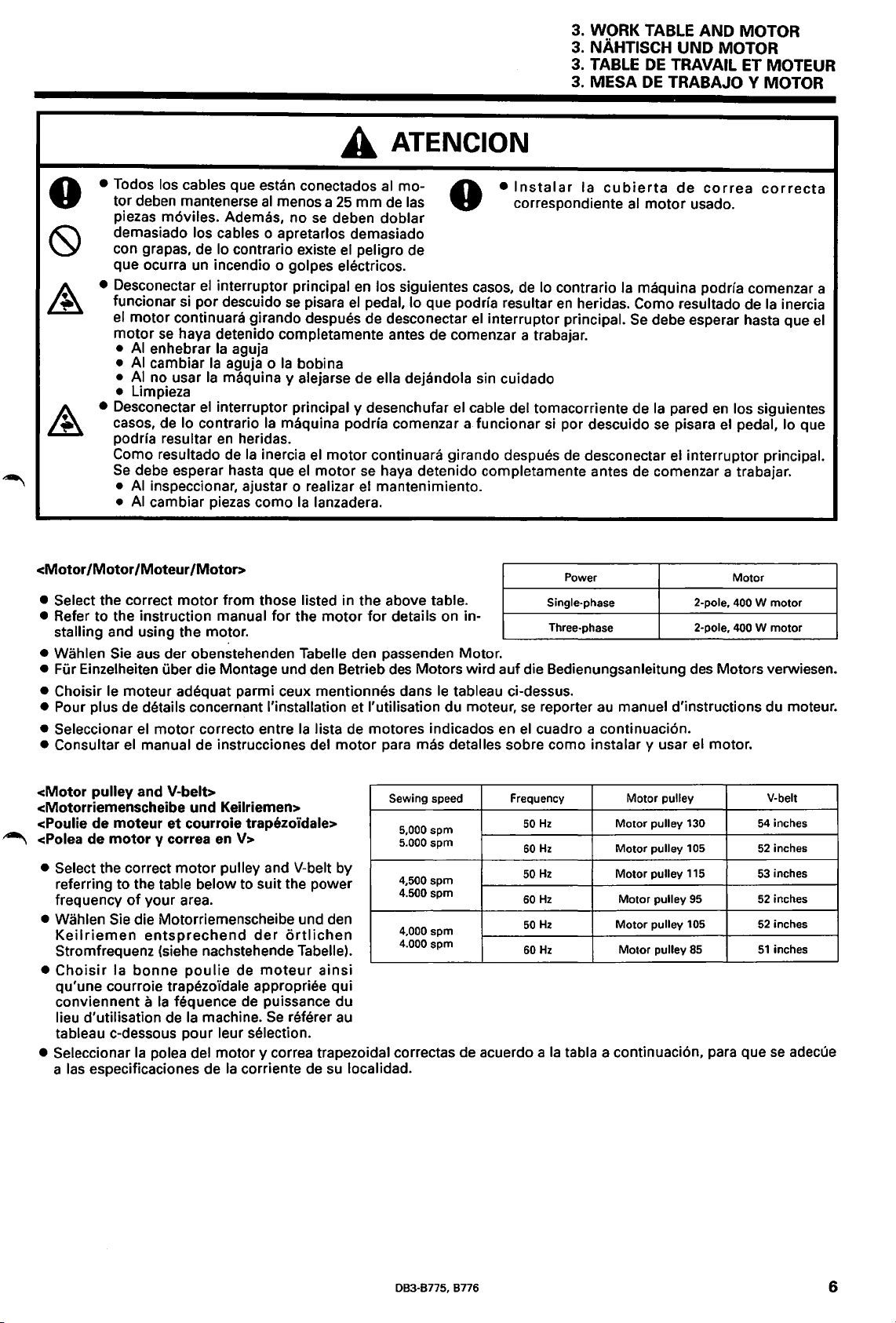
3. WORK TABLE AND MOTOR
3.
NAHTISCH UNO MOTOR
3. TABLE
3.
MESA
DE
TRAVAIL ET MOTEUR
DE
TRABAJO V MOTOR
A
• Todos los cables que estan conectados
tor deben mantenerse
piezas m6viles. Ademas, no
demasiado
los cables o apretarlos demasiado
con grapas, de
que ocurra
• Desconectar
funcionar
el
motor continuara girando despues de desconectar
motor
•
AI
•
AI
•
AI
un
incendio o golpes electricos.
el
si
por descuido
se
haya detenido completamente antes de comenzar a trabajar.
enhebrar
cambiar
no usar
Ia
Ia
al
menos a
lo contrario existe
25
se
deben doblar
el
interrupter principal
se
pisara
Ia
aguja
aguja o
Ia
bobina
maquina y alejarse de ella dejandola sin cuidado
ATENCION
al
mo- A
mm
de las V
peligro de
en
los siguientes casos,
el
pedal, lo que podria resultar
el
interrupter principal.
• Limpieza
<Motor
• Desconectar
casas, de
podria resultar
Como resultado de
Se
debe esperar hasta que
•
AI
inspeccionar, ajustar o realizar
•
AI
cambiar piezas como
/Motor
/Moteur
el
interrupter principal y desenchufar
lo contrario
en
Ia
maquina podria comenzar a funcionar
heridas.
Ia
inercia
el
motor continuara girando despues
el
motor
se
el
Ia
lanzadera.
/Motor>
el
cable del tomacorriente de
haya detenido completamente antes de comenzar a trabajar.
mantenimiento.
• Select the correct motor from those listed in the above table.
• Refer to the instruction manual for the motor
for
details on in-
stalling and using the motor.
• Wahlen Sie aus der obenstehenden Tabelle den passenden Motor.
• Fur Einzelheiten uber die Montage und
• Choisir le moteur adequat parmi ceux mentionnes dans
den
Betrieb
des
Motors wird auf die Bedienungsanleitung
le
tableau ci-dessus.
• Pour plus de details concernant !'installation et I' utilisation du moteur,
• Seleccionar
• Consultar
el
motor correcto entre
el
manual de instrucciones del motor
Ia
lista de motores indicados
para
mas detalles sabre como instalar y usar
•
lnstalar
Ia
cubierta
correspondiente
de
lo contrario
en
heridas. Como resultado de
si
por descuido
de
desconectar
Power
Single-phase
Three-phase 2-pole,
se
reporter
en
el
cuadro a continuaci6n.
au
de
correa
al
motor
usado.
Ia
maquina podria comenzar a
Se
debe esperar hasta que
Ia
pared
en
se
pisara
el
interrupter principal.
2-pole,
des
correcta
Ia
inercia
el
los siguientes
el
pedal, lo que
Motor
400 W motor
400 W motor
Motors verwiesen.
manuel d'instructions du moteur.
el
motor.
<Motor
pulley and V-belt>
<Motorriemenscheibe und Keilriemen>
,-.,
<Poulie
<Polea de
de
moteur
motor
et
courroie trapezoidale>
y correa en V>
• Select the correct motor pulley and V-belt by
referring to the table below to suit the power
frequency
• Wahlen
Keilriemen
of
your area.
Sie
die Motorriemenscheibe und den
entsprechend
der
Stromfrequenz (siehe nachstehende Tabelle).
Choisir
•
Ia
bonne
poulie
de
moteur
qu'une courroie trapezo'idale appropriee qui
a
Ia
conviennent
lieu d'utilisation de
fequence de puissance du
Ia
machine.
Se
tableau c-dessous pour leur selection.
• Seleccionar
las
a
Ia
polea del motor y correa trapezoidal correctas de acuerdo a
especificaciones de
Ia
corriente de
ortlichen
ainsi
referer
au
su
Sewing speed
5,000
5.000
4,500 spm
4.500 spm
4,000 spm
4.000 spm
localidad.
spm
spm
Frequency Motor
50
Hz
60Hz
50
Hz
60Hz
50
Hz
60Hz
Ia
tabla a continuaci6n, para que
Motor
Motor
Motor
Motor
Motor
Motor
pulley
pulley 130
pulley 105
pulley
115
pulley
95
pulley
105
pulley
85
54
52
53
52
52
51
V-belt
inches
inches
inches
inches
inches
inches
se
adecue
DB3-B775, B776
6
Page 30
4. INSTALLATION
4. MONTAGE
4.
INSTALLATION
4.
INSTALACION
4.
INSTALLATION
4.
MONTAGE
4.
INSTALLATION
4.
INSTALACION
(9
0
0
(9
0
0
A
• The sewing machine should only be installed
by a qualified technician.
• Ask your Brother dealer or a qualified electrician
be
• The sewing machine weights more than
The installation should
or
• Die Nahmaschine darf nur von einem qualifizierten Fachmann montiert werden.
• Falls Elektrikerarbeiten gemacht werden mussen,
oder
• Weil die Nahmaschine mehr als
sind zur Montage mindestens zwei Personen
notwendig.
CAUTION/ ACHTUNG/ ATTENTION/ATENCION
for
any electrical work that may need to
done.
38
kg.
be
more people.
wenden
an
Sie
sich
an
lhren Brother-Handler
einen qualifizierten Elektriker.
carried
38
out
kg
by
two
wiegt,
(9
•
•
•
• Install the belt cover to the machine head.
0
• SchlieBen Sie das Netzkabel erst nach abge-
(9
• Erden Sie die Maschine unbedingt.
•
• Bringen Sie
0
Do
not
connect the power cord until installa-
Bei
will
falsch
tion is complete, otherwise the machine
operate
which could result in injury.
Be
connection is not secure, serious electric shocks
will result.
schlossener Montage an,
unbeabsichtigte Betatigung des Pedals die
Maschine in Gang gesetzt und Verletzungen
verursachen kann.
geerdeter Maschine besteht die Gefahr eines
elektrischen Schlages.
oberteil an.
if
the treadle is pressed by mistake,
sure to connect the ground.
weil sonst durch eine
den
Riemenschutz
If
the ground
am
Maschinen-
(9
0
0
(9
0
0
• L'installation de
exclusivement a
• Pour tout travail concernant
que, s'adresser a un concessionnaire Brother done de causer des blessures.
a
un
ou
•
La
tallation necessite done
personnes ou plus.
•
La
nal especializado.
• Consultar a
cista calificado por cualquier trabajo de electricidad que
•
La
instalaci6n debe ser realizada por dos o mas peligro de sufrir golpes electricos serios.
personas.
electrician qualifie.
machine a coudre
maquina debe ser instalada
maquina de coser
Ia
machine
un
technician qualifie. avant d'avoir termine !'installation, sinon
pese
le concours de deux
su
distribuidor Brother o
se
debiera realizar.
pesa
doit
etre confiee
• Ne pas brancher le cordon
(9
machine risquera de
le
systeme electri- on enfonce accidentellement
• Veiller a bien brancher
plus de
38
kg.
L'ins-
le
branchement de terre n'est pas bien fait, il y
aura risque d'electrocution grave.
se
•
• Installer le couvercle de courroie sur
machine.
• No conectar
ber completado
Ia
maquina podria comenzar a funcionar
descuido
sultar
• Asegurarse de hacer
conexi6n a tierra no fuera segura,
en
heridas.
el
cable de alimentaci6n hasta ha-
Ia
instalaci6n, de lo contrario
se
pisara
el
pedal, lo que podrfa re-
Ia
s61o
mas de
por perso-
un
electri-
38
kg.
La
0
(9
•
0
• lnstalar
Ia
Ia
maquina.
cubierta de
Ia
d'alimentation
mettre
Ia
machine a
conexi6n a tierra.
correa
en
en
Ia
Ia
marche
pedale,
Ia
terre.
Ia
tete de
si
se
corre
cabeza
por
Si
Ia
si
et
Si
Ia
el
de
7 083-8775, 8776
Page 31

4-1. Installing the machine head
4-1. Montage des Maschinenoberteils
Installation de
4-1.
4-1. lnstalacion de Ia cabeza de
Ia
tete de machine
Ia
maquina
4. INSTALLATION
4. MONTAGE
4. INSTALLATION
4. INSTALACION
1.
Install the
threaded sides
2. Insert the
chine head installation holes in the work table
the four washers
the rubber cushion pins
the
four
3. Insert the four rubber cushions
ion pins
4. Place the machine head 0 on
cushions
1.
8ringen Sie die Sprengringe 0
Nuten der vier Gummidampferstiften
2. Stecken Sie
Montagelocher im Nahtisch 8
und bringen
Federscheiben
und ziehen
3.
8ringen
Gummidampferstiften
4.
Stellen
Gummidampfer
four
stop
rings 0 to
of
the four rubber cushion pins
four
rubber cushion pins
the
f)
grooves
into the
8 and the four spring washers 0 onto
f),
nuts
f).
f).
0.
and then secure them
f)
onto the rubber cush-
top
of
the
an
den gewindeseitigen
8 an.
die
vier
Gummidampferstifte
fUr
das Maschinenoberteil
Sie die vier Unterlegscheiben 8 und die vier
0
an
Sie die vier Muttern 0 fest.
Sie
Sie
das
den Gummidampferstiften
die
vier
Gummidampfer
f)
Maschinenoberteil 0 auf
f).
an.
four
e,
four
f)
8 an
die
on the
f).
ma-
place
with
rubber
in
die
f)
den
vier
an
1. Installer les quatre bagues de blocage 0 sur les rainures des cotes filetes des quatre broches
caoutchouc.
2.
lnserer les quatre broches
Ia
table de travail
de
en
caoutchouc, puis les fixer a l'aide des quatre ecrous
3. lnserer les quatre coussinets en caoutchouc 8 sur les broches
Ia
4. Placer
1. lnstalar los cuatro aros de retenci6n 0
de caucho
tete de machine 0 sur les quatre coussinets en caoutchouc
f).
2. lnsertar los cuatro pasadores de almohadillas de caucho
maquina
de almohadillas de caucho
en
Ia
mesa de trabajo
3. lnsertar las cuatro almohadillas de caucho 8
4. Colocar
8776
Ia
cabeza de
f)
des coussinets
8,
placer les quatre rondelles 8 et les quatre ronde lies a ressort 0 sur
en
caoutchouc dans les quatre trous d'installation de
0.
f)
des coussinets en caoutchouc.
f).
en
las ranuras en los lados roscados de los cuatro pasadores
f)
en
los cuatro orificios de instalaci6n de
8,
colocar las cuatro arandelas 8 y las cuatro arandelas
f)
y luego asegurarlas con cuatro tuercas
en
los pasadores de almohadillas de caucho
Ia
maquina 0 encima de las cuatro almohadillas de caucho
5.(8776)
Pass
foot lever
it
0.
the connecting rod joint 0 through the hole in the
Cii)
as
with
nuts
shown in the illustration,
4J)
and tf).
f).
les
de
resorte 0
f).
broches
5. (8776)
Stecken
Abbildung gezeigt durch das
Sie die Muttern
5.
(8776)
Faire passer le raccord 0 de tige
trou du levier de pied presseur
!'illustration, puis le serrer a l'aides des ecrous
Sie den Zwischenstangenzapfen 0
Pedalhebelloch 0 und
4J)
und tf) fest.
f)
des coussinets en
Ia
tete de machine
f)
des coussinets
de
almohadillas
Ia
cabeza de
en
los pasadores
and
then tighten
wie
de
connexion par le
~
comme indique sur
4J)
Ia
in der
ziehen
et tf).
5. (8776)
Pasar
Ia
orificio
Ia
083-8775, 8776
union de
en
Ia
palanca del pedal ~ tal como
figura, y luego apretarla con las tuercas
Ia
varilla de conexi6n 0 a traves del
se
indica en
4J)
y tf).
8
Page 32

4. INSTALLATION
4.
MONTAGE
4.
INSTALLATION
4. INSTALACION
4-2. Installing
the
belt
cover
4-2. Montage des Riemenschutzes
Installation du couvercle de courroie
4-2.
4-2.
lnstalacion de
1.
Secure the auxiliary belt cover 0 to the work table with
the three wood screws
2.
Secure the bobbin winder bracket 8 to the auxiliary belt
cover
0 with the three screws
ers
0,
3.
1.
2.
3.
1.
2.
the three washers 8 and the three nuts
Tighten the silver stud
Befestigen Sie den Hilfsriemenschutz 0
Holzschrauben
Nahtisch.
Befestigen Sie
Schrauben
Unterlegscheiben
Hilfsriemenschutz
Ziehen Sie den silberfarbenen
Fixer
le
vail a l'aide
Fixer le support 0 de bobineur de canette
0,
couvercle 0
des
Ia
cubierta de
f)
and the three washers
0,
the three spring wash-
~.
f)
und den drei Unterlegscheiben 0 am
die
Spulerhalterung 0 mit
den
drei
Federscheiben
f)
und
den
drei
Muttern
0.
de
trois vis a bois
courroie auxiliaire a
Stitt~
f)
fest.
et
des
trois rondelles e.
0 de courroie auxiliaire a l'aide des trois vis
rondelles
ecrous
3.
Serrer le pivot
e.
a ressort
0,
en
argent (D.
des trois rondelles
Ia
correa
e.
mit
den drei
den
0.
den
e am
Ia
table
au
couvercle
0.
des trois
f)
et des trois
e.
de
drei
drei
tra-
r-
1.
Asegurar
e.
2.
Asegurar
de resorte
3.
Apretar
8. Bringen
scheibe ~ an.
9.
Kontrollieren Sie, ob die Riemenschutze die Riemenscheibe nicht beri.ihren und ziehen Sie die Schrauben G) und
fest.
4.
Placer
5.
Visser provisoirement
6.
Faire passer
courroie
7.
De
avec
8. Serrer provisoirement le couvercle de courroie
rondelle a ressort
9.
S'assurer que les couvercles
4.
Colocar
5.
Atornillar provisoriamente
6.
Pasar
con
7.
De
riamente con el tornillo G).
8. Apretar provisoriamente
de resorte
9.
Despues de verificar que
Ia
cubierta de
Ia
mensula del bobinador 0 a
0.
las tres arandelas
el
esparrago plateado
Sie
den Riemenschutz
Ia
courroie trapezo'idale 0 sur
Ia
courroie trapezo'idale 0 par le couvercle de courroie
UE
tD
Ia
meme
Ia
vis
Ia
el
tornillo G).
Ia
misma manera, colocar
sur
manii~re,
(D.
Ia
correa
correa
en
Ia
Ia
Ia
vis G).
placer le couvercle de courroie
~.
en
V 0
V 0 por
e.
correa auxiliar 0 a
f)
y las tres tuercas e.
~.
UE
a!>
vis G) et
en
Ia
las
Ia
rondelle a ressort
ne
touchent pas
Ia
polea de
el
tornillo
Ia
cubierta de
Ia
cubierta de
cubierta de
cubiertas no estan tocando
Ia
Ia
cubierta de
und den Riemenschutz
Ia
poulie
Ia
Ia
maquina y luego pasarla a traves de
G)
y
Ia
arandela de resorte
Ia
correa
Ia
Ia
correa
mesa
de trabajo con los tres tornillos de madera 8 y las tres arandelas
Ia
correa auxiliar 0 con los tres tornillos
4.
Place
the V-belt 0 onto the machine pulley and then
it
through the work table.
5.
Provisionally screw the screw G) and the spring washer
fD
onto the stud
6.
Pass
the V-belt 0 through belt cover
align the groove
7.
In the same way, place belt cover
pulley, and then provisionally tighten
G).
8. Provisionally tighten belt cover
tB
with
9.
After checking that the covers are not touching the machine pulley, securely tighten screws G) and
4.
Legen
flihren Sie ihn durch den Nahtisch.
5.
Bringen Sie die Schraube
provisorisch am
6.
Fi.ihren Sie den Keilriemen 0 durch den Riemenschutz
UE
Schraube
7.
Bringen Sie den Riemenschutz
scheibe
Schraube
de
machine puis
fD
sur le
TE
CB
sur
UE
tD
et le couvercle de courroie
poulie de machine, puis serrer fermement les vis
UE
4@,
y luego alinear
correa
UE
tD
TE
y
Ia
tB
sobre
Ia
cubierta de
polea de
the screw
Sie
tD
und richten
an
TE
CB
provisorisch
Ia
faire passer a travers
pivot~.
UE
Ia
poulie de machine, puis le serrer provisoirement
fD
en
Ia
polea de
Ia
maquina, apretar firmemente los tornillos G) y
~.
of
belt cover
41)
and the spring
den
Keilriemen 0 auf die Riemenscheiben und
Stitt~
(D
aus.
und befestigen Sie ihn provisorisch
(D.
4@,
puis aligner
el esparrago
Ia
ranura de
Ia
Ia
correa
an.
Sie
die Riemenschutznut
mit
der Schraube
TE
CB
Ia
mesa de trabajo.
~.
Ia
maquina, y luego apretarla proviso-
TE
tB
con
0,
las tres arandelas
UE
UE
G)
mit
Ia
table de travail.
Ia
rainure du couvercle de
a l'aide de
cubierta de
el
UE
a!>
with
TE
der Federscheibe
TE
tornillo
the screw G).
tB
over the machine
it
with
a!>
and belt cover
washer~.
CB
an
41)
und der Feder-
Ia
vis
(D
et
Ia
41)
tP),
the screw
41).
UE
der
41)
41).
correa
y
Ia
pass
and then
TE
fD
tD
auf die
Rieman-
mit
der
41)
et de
Ia
UE
tD
arandela
41).
r-"_
9
083·8775,
8776
Page 33

4.1NSTALLATION
4. MONTAGE
INSTALLATION
4.
4. INSTALACION
10. lnstalar
.-.._ 11. lnstalar provisoriamente
dos arandelas
Ia
cubierta de
11.
Ia
correa D
Ia
cubierta
4D
de manera que
de
Ia
correa D
10. Install belt cover D
cover
UE
$.
11.
Provisionally install belt cover D
bracket
10. Bringen Sie den Riemenschutz D
in der Mitte des Riemenschutzes
11. Bringen Sie den Riemenschutz D
e with the two
~so
screws
0 und den beiden Unterlegscheiben
der Spulerhalterung 8 an.
10. Installer le couvercle de courroie D
soit place
11. Installer provisoirement le couvercle
sur le support e du bobineur de canette a l'aide des
deux vis
se
encuentre
~en
Ia
mensula del bobinador 8 con los dos tornillos 0 y las
12.
Insert the cover
cover
the groove
13.
Slide the cover
D
4D
au
milieu du couvercle de courroie
0 et des deux rondelles
en
el
UE
as
medio de
tD
and belt cover D
of
far
as
Ia
cubierta de
tD
of
belt cover D
belt cover D
tD
down along the groove
it
will
go.
that
it
is in the middle
~to
0 and
~.
~-
the bobbin winder
the
two washers
~an,
so
daB er sich
UE
CD>
befindet.
4D
mit den Schrauben
II
provisorisch
CD
de
maniere qu'il
UE
de
courroie D
11.
Ia
correa
4D
in between the belt
and then place
UE
of
belt cover
of
$ .
it
belt
•.
an
$.
~
into
\\\
X X 0
12.
Bringen Sie die Abdeckung
4D
zwischen dem Riemenschutz
menschutz
Riemenschutzes D
13.
Schieben Sie die Abdeckung
Riemenschutzes
12.
lnserer le couvercle
entre
de
courroie
couvercle ~ de courroie
13.
Faire glisser bien a fond
long
12.
lnsertar
entre
correa D
de
13.
Ia
Deslizar
de
Ia
14.
Pull belt cover D
ance between the belt cover
belt cover D
15.
Fully tighten the
14.
Ziehen Sie am Riemenschutz D
dem Riemenschutz
Riemenschutzes D ~ kein Zwischenraum vorhanden ist.
15.
Ziehen Sie die beiden Schrauben 0 fest. (Siehe Schritt
11.)
.D
4D
an
und setzen Sie sie in die Nutdes
~
~
ganz nach unten.
tD
le couvercle
de
Ia
rainure du couvercle ~ de courroie
Ia
cubierta
Ia
cubierta de
~.
correa D
Ia
cubierta
cubierta
UE
D,
puis
tD
Ia
y luego colocarla
~-
tD
hacia abajo a lo largo de
de
Ia
correa D
~toward
CD.
two
UE
tD
des Riemenschutzes D
UE
tD
und dem Rie-
ein.
du couvercle
tD
le
de
correa
screws
tD
entlang der
$de
courroie D
de courroie et le couvercle
placer dans
D.
le
couvercle
Ia
cubierta de
UE
en
Ia
4D
tanto como
you until there is no clear-
UE
0.
tD
und der Abdeckung
Ia
rainure
tD
vers le
Ia
correa D
CD>
y
Ia
cubierta de
ranura de
tD
and
(Refer to step 11.)
~.
Ia
sea
the-
cover
so
daB zwischen
Nut
des
bas
D.
cubierta
Ia
ranura
posible.
tD
CD
des
~
du
le
~
Ia
of
14.
lirer
le couvercle
le couvercle
et
15.
Serrer completement les deux vis
14.
lirar
de
Ia
correa
15.
Apretar fuertemente los dos tornillos
UE
CD
de courroie D vers soi jusqu'a
CD
du couvercle
cubierta de
Gi)
y
Ia
cubierta
Ia
correa D
CD
CD
de courroie
de
Ia
ce
qu'il
ne
reste plus d'ecart entre le couvercle
0.
(Se
CD
hacia adelante hasta que no quede ninguna separaci6n entre
correa D
0.
D.
reporter a l'etape
CD.
(Consultar
el
paso
DB3-B775, 8776
11.)
11.)
UE
Gi>
de courroie
Ia
cubierta de
Ia
10
Page 34

4. INSTALLATION
4. MONTAGE
INSTALLATION
4.
4. INSTALACION
4-3. Installing
the
belt
4-3. Riemenmontage
4-3.
Installation de
lnstalaci6n de
4-3.
1.
Place the V-belt 0 onto the motor pulley
2. Turn the nut 8 to adjust so that there is
deflection
[force
Note:
in
the belt 0 when
of
5 N
(5
kgf)].
* While using the machine, the belt
pulley and cause the belt tension to loosen.
tension is too loose the following faults could occur.
a.
The stopping position may shift,
b. The
c.
d. An
e.
needle bar may
An extra stitch
stops,
abnormal noise may
and
The belt may become too loose and contact with the
cover.
Ia
courroie
Ia
correa
8.
13-
it
is pressed
drift
may
when the machine stops,
be sewing when the machine
be
heard due to belt slipping,
will
with
conform
16
mm
a finger
to
If
the belt
of
the
1. Bringen
2. Stellen Sie
eingedruckt werden kann [Kraft von 5
Hinweis:
Sie den Keilriemen 0
mit
der
Mutter
an
der Motorriemenscheibe 8 an.
8 die Riemenspannung ein, so daB
1\1
(5 kgf)).
der
Riemen
mit
* Nach einer gewissen Betriebszeit paBt sich der Riemen and die Riemenscheiben an,
verringert.
a.
Die Stopposition kann sich verschieben.
b.
Die Nadelstange kann sich verschieben, wenn die Maschine stoppt.
c.
Ein
d. Augfrund eines durchrutschenden Riemens
e.
Der
1.
Placer
2. Tourner l'ecrou 8 de maniere que
doigt
Remarque:
* Lorsqu'on utilise
alors. Si
a.
La
b.
La
c.
Un
d.
Un
e.
La
1.
Colocar
2.
Girar
dedo [con una fuerza de 5 N
Falls die Riemenspannung
zusatzlicher Stich kann genaht werden, wenn die Maschine stoppt.
Riemen kann
Ia
courroie trapezo"idale 0 sur
[force de 5 N
Ia
tension de
position
barre a aiguille pourra
point supplementaire pourra tre cousu lorsque
bruit anormal pourra tre em is lorsque
courroie pourra
Ia
correa
Ia
tuerca 8 para ajustar de manera que
Ia
d'arrt
en
zu
locker werden und die Abdeckung beruhren.
(5
kgf)].
machine,
pourra
V 0
Ia
Ia
courroie est trop faible, les anomalies suivantes risqueront de
se
decaler,
se
se
detendre excessivement et entrer
en
Ia
(5
zu
gering ist, kann
kann
Ia
poulie
de
Ia
courroie 0 s'enfonce
courroie s'adaptera progressivement a
decaler lorsque
polea del
kgf)).
motor
moteur
Ia
Ia
courroie glisse, et
8.
Ia
correa 0 tenga un deflexi6n de
es
zu
den folgenden Fehlern kommen.
es
zu
einem ungewi:ihnlichen Betriebsgerausch kommen.
8.
de
13-
16
mm
machine s'arrete, r-"
Ia
machine s'arrete,
en
contact avec le couvercle.
Ia
lorsqu'on appuie sur
poulie et
einem Finger urn 13 bis 16
so
daB sich die Riemenspannung
Ia
courroie 0 avec
Ia
tension de
13-
16
Ia
se
mm
courroie diminuera
produire.
al presionarla con un
mm
un
Nota:
* Cuando
correa queda demasiado floja, pueden producirse los siguientes problemas.
a.
b.
c.
d. Puede escucharse un ruido
e.
11
se
utiliza
Ia
maquina,
La
posicion de parada puede cambiar.
La
barra de agujas puede correrse al parar
Puede coserse una puntada adicional al parar
La
correa puede aflojarse demasiado y entrar
Ia
correa
anormal debido a que
se
adaptara a
Ia
Ia
forma de
maquina,
Ia
maquina,
Ia
correa patina, y
en
contacto con
083-8775,
8776
Ia
polea y
Ia
cubierta.
Ia
tension
de
Ia
correa disminuira.
Si
Ia
Page 35

4. INSTALLATION
4. MONTAGE
4. INSTALLATION
4.
INSTALACION
3.
Secure the motor belt cover 8 and the auxiliary motor
belt cover 0 with the
four
screws 0
as
shown in the
illustration.
Position the belt covers so that they do not touch the
V-belt 0 at this time.
3.
Befestigen Sie den
Hilfsriemenschutz
der
Abbildung gezeigt.
Die
Riemenschutze mussen
Motorriemenschutz 8 und
0
mit
den vier Schrauben 0 wie in
so
positioniert werden,
sie den Keilriemen 0 nicht beruhren.
3.
Fixer le
couvercle
couvercle
8 de
courroie
de
moteur
0 de courroie de moteur auxiliaire a
I'
aide
quatre vis 0 comme indique sur !'illustration.
Placer les couvercles
touchent pas
3.
Asegurar
cubierta de
Ia
Ia
cubierta de
Ia
correa del motor auxiliar 0 con los cuatro
tornillos 0 tal como
Ubicar
toquen
las cubiertas de
Ia
correa
de courroie de maniere qu'ils
courroie trapezo'idale 0 a
Ia
en
se
V
correa del
indica
en
Ia
correa de manera que no
0.
Ia
figura.
motor
ce
moment.
8 y
den
daB
et
le
des
ne
Ia
4.
Regier
5.
Desserrer
6.
Aligner le bossage de
7.
Serrer
8.
9.
10.
Aligner le centre de
11.
Apres le reglage, resserrer
Ia
retenue de courroie E).
Ia
vis
f).
Ia
vis
f).
Regier le protege-doigts.
Desserrer
Ia
vis
~.
Ia
retenue de courroie E) sur le repere
Ia
vis~
sur le repere
Ia
vis~.
(J).
4.
Adjust the belt retainer
5.
Loosen the screw
6.
Align the boss
7.
lighten
8.
Adjust the finger protector.
9.
Loosen the screw
10.
Align the center
11.
After adjusting, tighten the
4.
Stellen Sie den Riemenhalter E) ein.
5.
Losen Sie die Schraube
6.
Richten Sie den Zapfen des Riemenhalters e auf die
of
the screw
e.
f).
the belt retainer e with the mark
f).
~.
of
the screw (i) with the mark
screw~.
f).
Markierung 0 aus.
7.
Ziehen Sie die Schraube 8 fest.
8.
Bringen Sie den Fingerschutz
9.
Losen Sie die Schraube
10.
Richten Sie die Schraubenmitte
(J)
aus.
11.
Ziehen Sie
nach
dem Einstellen die Schraube
tlil.
an.
~auf
die Markierung
fest.
0.
(J).
(i)
wieder
0.
4.
Ajustar
5.
Aflojar
6.
Alinear
7.
Apretar el tornillo
8.
Ajustar
9.
Aflojar
10.
Alinear
11.
Despues de ajustar, apretar
el
retenedor de
el
tornillo
el
cuba del retenedor de
el
protector de dedos.
el
tornillo
el
centro del
Ia
f).
f).
~.
tornillo~
correa
e.
Ia
correa E) con
con
Ia
marca
el
tornillo~.
Ia
CD.
DB3·B775, 8776
marca
0.
12
Page 36

4. INSTALLATION
4. MONTAGE
4. INSTALLATION
4. INSTALACION
4-4. Installing the bobbin winder
4-4. Montage des
Spulers
4-4. Installation
4-4.
lnstalaci6n de
1.
Push down the bobbin presser arm 0 as far
go.
2.
Place the bobbin
8 by approximately 5 mm, and then place the bob-
belt
bin winder so that
work table.
3.
Install the bobbin winder with the two screws G and the
two
4.
washers
Pull the bobbin presser arm 0 back and check that there
is approximately 8
winder
bin
1.
Drlicken Sie den Spulenarm 0 so weit wie moglich nach
unten.
2.
Positionieren Sie das Spulerrrad
8 um ungefahr 5
den Spuler parallel zur Riemenoffnung im Nahtisch aus.
3.
Bringen
den beiden Unterlegscheiben
4.
Ziehen Sie den Spulenarm 0 zuruck und kontrollieren
Sie, ob der Abstand zwischen dem Spulerrad
Riemen
1.
Abaisser
2.
Placer
qu'elle pousse
le bobineur de canette parallelement
dans
3.
Installer le bobineur de canette a l'aide des deux vis G et des deux rondelles
4.
Tirer le bras 0 du presseur de canette vers l'arriere et verifier qu'il y ait un ecart d'environ 8 mm entre
Ia
bobineur de canette et
courroie
8.
Sie
8 ungefahr 8
au
Ia
roue
Ia
table de travail.
du
bobineur de canette
Ia
bobinadora
winder
wheel
f)
it
is parallel with the belt hole in the
0.
mm
of
clearance between the bob-
wheel
f)
and the belt
mm
den Spuler
eingedruckt wird und richten Sie
mit
8.
f),
den beiden Schrauben G und
0 an.
mm
betragt.
maximum
f)
Ia
le
bras 0 du presseur de canette.
du
bobineur
courroie 8 d'environ 5 mm, puis placer
de canette de maniere
0.
so that
it
so
daiS
au
trou de courroie
Ia
as
it
will
pushes the
der Riemen
f)
und dem
roue
f)
du
r-"'
1.
Empujar hacia abajo tanto como
2.
Colocar
bobinadora de manera que quede paralela con el orificio de
3.
lnstalar
4.
Tirar del brazo presionador de
mm
Ia
rueda
de
Ia
bobinadora
el
bobinador con los dos tornillos 0 y las dos arandelas
entre
Ia
rueda de
Ia
bobinadora
sea
posible
f)
de manera que empuje
el
brazo presionador de
Ia
Ia
correa 8 aproximadamente 5 mm, y fuego colocar
correa
0.
Ia
bobina 0 hacia atras y verificar que exista una separaci6n de aproximadamente 8
f)
y
Ia
correa
8.
4-5. Installing the presser lifter pedal (8775)
4-5. Montage des
Installation de
4-5.
4-5.
lnstalaci6n del pedal levantador del prensatelas (8775)
Stoffdri.ickerfuBpedals (8775)
Ia
pedale du releve-presseur (8775)
• Install the presser lifter pedal and the chain
in
the illustration.
• Montieren Sie das StoffdruckerfufSpedal und die Kette
wie in der Abbildung gezeigt.
• Installer
chainette de
•
lnstalar
cadena tal como
Ia
bobina
en
Ia
pedale de releveur de pied presseur
el pedal del
0.
Ia
mesa de trabajo.
Ia
maniere indiquee sur ('illustration.
levantador
se
muestra
del prensatelas y
en
Ia
figura.
as
Ia
shown
et
Ia
Ia
13
083·8775,
8776
Page 37

4.1NSTALLATION
4. MONTAGE
4.1NSTALLATION
4. INSTALACION
4-6. Connecting
4-6.
AnschluB der Kabel (8776)
the
cords (8776)
4-6. 8ranchement des cordons (8776)
4-6.
Conexion de los cables (8776)
A DANGER/GEFAHR/DANGER/PELIGRO
• Wait at least 5 minutes after turning
Touching areas where high voltages are present can result in severe injury.
•
Warten
Schaltkastenabdeckung offnen. Weil Hochspannung vorhanden ist, besteht bei Beruhrung von Teilen eine
hohe Verletzungsgefahr.
• Attendre
couvercle du boitier de commande. Certains composants
blessures si on les touche.
• Despues de desconectar
caja de controles.
A
~~--------------------------------------------------------------~
8
8
8
e
• Turn
control box may result.
• Confirm that the plug is not disconnected
• Secure the cords so that they do not touch the belt, otherwise the cord insulation may become damaged
while
• Always ground the power supply
plete grounding could lead to electric shocks.
•
Do
Sie
nach
dem
Ausschalten
au
moins 5 minutes apres avoir mis l'interrupteur principal
el
interruptor principal esperar al menos 5 minutos antes de abrir
El
tocar las areas donde exista alto voltaje puede ocasionar heridas graves.
CAUTION/
off
the power switch before connecting and disconnecting the power cord, otherwise damage to the
the machine
not clamp the cords inside the control box when closing the cover.
is
operating, which could cause damage to the control box.
ACHTUNG/
off
the
des
of
the 3-phase
power
Neetzschalters
switch before opening the cover
mindestens 5 Minuten,
en
position d'arret avant
se
trouvant
so
us
haute tension, on risque de graves
ATTENTION/ ATENCION
or
loosened before turning on the power switch.
motor
and single-phase
220 V to
240
of
the control box.
bevor
V motors. Incom-
d'ouvrir
Ia
tapa de
Sie
die
le
Ia
&
8
8
8
e
&
8
8
8
e
&
8
8
8
e
&
• Schalten Sie den Netzschalter
Schaltkasten beschadigt werden kann.
• Vor dem Einschalten des Netzschalters ist darauf
• Sichern Sie
Kabelisolation kann
•
lmmer die Stromversorgung
Unzureichende Erdung kann
• Klemmen Sie beim SchlieBen der Schaltkastenabdeckung nicht die Kabel ein.
•
Mettre
d'alimentation, sinon le boitier
• S'assurer que
position de marche.
• Fixer les cables de maniere qu'ils
deteriorer pendant
• Toujours brancher
de terre n'est pas bien
•
Ne
pas pincer les cables dans
• Desconectar
se
podrfa daiiar
• Confirmar que el enchufe no
• Asegurar los cables de manera que no toquen Ia correa, de lo contrario
daiiar mientras
• Conectar siempre
V.
Una mala conexi6n a tierra puede provocar una sacudida eh!!ctrica.
•
No apretar los cables dentro de
die
Kabel, so daB sie den
zu
l'interrupteur
Ia
fiche n'est
le
le
el
interruptor principal antes de conectar o desconectar
Ia
caja de controles.
Ia
maquina esta funcionando, lo cual podrfa danar
Ia
Beschadigungen des Schaltkastens fUhren.
principal
fonctionnement de
fil de terre du moteur triphase et des moteurs mono phases de
branche, il y aura risque d'electrocution.
fuente de alimentaci6n del
vor
dem AnschlieBen
Keilriemen
des
dreiphasigen Motors und des einphasigen Motors
zu
elketrischen Schlagen fuhren.
en
position
de
commande risquera d'etre endommage.
pas
debranchee ou mal engagee avant
ne
touchent pas
le
boitier de commande lorsqu'on referme
esta
desconectado o aflojado antes
Ia
caja de controles al cerrar
Ia
machine,
d'arret
motor
und
Losen des Netzkabels aus,
zu
achten, daB der Netzstecker richtig angesteckt ist.
nicht
beruhren konnen. Eine
avant
de
brancher
de
mettre l'interrupteur principal sur
Ia
courroie, sinon !'isolation des cables risque de
ce
qui pourrait endommager
el
cable de alimentaci6n,
de
conectar
Ia
caja de controles.
trifasico y los motores monofasicos de 220 V a
Ia
tapa.
et de
le
Ia
weil
sonst
der
durchgescheuerte
(220
V bis
240
V)
erden.
debrancher
le
boitier
220
V a
couvercle.
el
interruptor principal.
aislaci6n del cable se podrfa
le
cordon
de
commande.
240
V.
de
lo contrar.io
Ia
se
Si le fil
240
083-8775.
8776
14
Page 38

4.1NSTALLATION
4.
MONTAGE
4. INSTALLATION
4. INSTALACION
30
~
l
-
1.
Installer l'unite pneumatique 0 sous
2.
Installer l'interrupteur d'alimentation 8 sous
!'illustration.
3.
Brancher le fil
vert
j!__'i
"-r~~
:o
o:
1 I
30mm
~===~;
et jaune du cordon d'alimentation
~
DO
110
110
110
Ia
1.
Install the air
with
the
iII ustration.
2.
green/yellow
griin/gelbe
vert/jaune
mm
verde/amarillo
table de travail a l'aide des deux vis a bois a
Ia
table
de
Install the power switch 8 to the underside
table
with
in the illustration.
3.
Connect the green/yellow
the ground.
1.
Bringen
Holzschrauben
Unterseite des Nahtisches an.
2.
Montieren
Holzschrauben
Unterseite des Nahtisches an.
3.
SchlieBen Sie das grGn/gelbe Kabel des Netzkabels 8
der Masse an.
travail a l'aide des deux vis a bois a
f)
a
Ia
terre.
two
the
Sie
unit
0 to the underside
wood
two
die
in
Sie
den
in
of
the work table
screws in the position shown in the
of
the
work
wood
screws in the position shown
wire
of
the power cord 8
Drucklufteinheit 0 mit
der
gezeigten
Netzschalter 8 mit
der
gezeigten
Ia
position indiquee sur !'illustration.
Position
Position
Ia
position indiquee sur
den
den
zwei
an
der
beiden
an
der
an
to
~
1.
lnstalar
indicada
2.
lnstalar
indicada
3.
Conectar
Ia
unidad de aire 0
en
Ia
figura.
el
interrupter principal 8
en
Ia
figura.
el
cable verde/amarillo del cable de alimentacion 8 a tierra.
en
Ia
parte de abajo de
en
Ia
parte de abajo de
Ia
mesa de trabajo con dos tornillos de madera
Ia
mesa
4.
5.
6.
7.
8.
9.
4.
5.
6.
7.
8.
9.
en
Ia
posicion
de trabajo con dos tornillos de madera
Pass
the solenoid harness 0 and the synchronizer cable
8
down
through the hole in the work table.
Remove the
cover
Connect the solenoid harness 0
in the illustration.
Connect the valve harness 0 to the connector shown in
the illustration.
Close the motor cover
Connect the
shown in the illustration.
FOhren Sie
Synchronisatorkabel
Entfernen Sie die Motorschraube 8 und offnen Sie die r-"
Motorabdeckung
SchlieBen Sie den Solenoid-Kabelbaum 0
Stecker an.
SchlieBen Sie den Ventilkabelbaum 0 am gezeigten
Stecker an.
SchlieBen Sie die Motorabdeckung 8 und ziehen Sie die
Schraube
SchlieBen Sie das Synchronisatorkabel 8 am gezeigten
Stecker an.
e.
motor
synchronizer
den
Solenoid-Kabelbaum
e.
8 fest.
screw
8.
and then open the
to
8,
and then tighten the screw
cable 8
f)
durch das Loch im Nahtisch.
en
Ia
posicion
motor
the connector shown
to
the
connector
0
am
f).
und
das
gezeigten
4.
Faire passer le faisceau de solemo'ide 0
travail.
5.
Retirer
6.
Brancher le faisceau de soleno"ide 0 au connecteur montre sur l'illustration.
7. Brancher le faisceau de clapet
8.
Fermer le couvercle de
9.
Brancher le cable
4.
Pasar
trabajo.
5.
Desmontar el tornillo del
6.
Conectar el mazo
7. Conectar
8.
Cerrar
9.
Conectar
Ia
vis
f)
du moteur, puis ouvrir le couvercle 8
0
au
moteur
f)
du synchroniseur
el
mazo de conductores del solenoide 0 y el cable del sincronizador 8 hacia abajo por
de
conductores del solenoide 0
el
mazo de conductores del solenoide 0
Ia
cubierta del
el
cable del sincronizador 8
motor
8 puis serrer
motor
8.
0.
y luego apretar
15
et
le cable de synchroniseur 8 par le bas a travers le trou de
de
moteur.
connecteur montre sur !'illustration.
Ia
vis
f).
au
connecteur montre sur l'illustration.
y luego abrir
al
conector indicado
Ia
cubierta del
al
conector indicado
al
conector indicado
el
tornillo
083-8775,
8.
en
8776
motor
Ia
figura.
8.
en
en
Ia
figura.
Ia
figura.
el
orificio
en
Ia
table de
Ia
mesa de
Page 39

Approx.40V
Etwa
40V
Environ40V
Aprox.40V
Resistor
Widerstand
Resistance
Resistencia
Air
valve
Luftventil
Soupape pneumatique
Valvula
de
aire
4. INSTALLATION
4. MONTAGE
4. INSTALLATION
4. INSTALACION
Note:
* The puller output is output
from
the option output during machine operation with the settings made at shipment from the factory.
* Note the following points when connecting
tion
output
a.
Connect a solenoid
10 Q or
b.
The
lent
terminals.
or
air valve
with
greater.
voltage between the terminals should be equiva-
to
40 V DC.
When connecting
an
to
the op-
a resistance
air valve, connect a resistor in series so that the rated voltage is
obtained.
c.
Never short circuit the output terminals.
of
plug
12-pin
12
poliger Stecker
a
12
Fiche
Enchufe de
12-pin plug No.
12poliger Stecker Nr.
Fiche
a
12
broches
12
Enchufe de
Thread
Fadenabschneidersolenoid
Soll~noide
Solenoide del cortahilos
Thread
Fadenwischerdruckluftventil
Clapet d'air
Valvula
!Reverse solenoid)
IUmkehrsolenoid)
ISolenoide de couture arriere)
ISolenoide de marcha atras)
!Actuator switch)
IBetriebsschalter)
Unterrupteur d'actionneur)
Unterruptor del actuador)
Option output
Zusatzausgang
Sortie d'option
Salida opcional
Ground
Masse
Terre
Conexi6n a tierra
Spare
Frei
Rechange
Repuesto
clavijas No.
trimming
wiper
de aire
solenoid
du
coupe du fil
air valve
du
tire-fils
dellimpiahilos
broches
No.
@@
<D®
®@
®@
CD®
@
®
12
clavijas
Hinweis:
* Der
Zieherausgang
wird
wahrend
des
Maschinen-
betriebs am Zusatzausgang ausgegeben, wenn die ab
vorgenommenen
Werk
Einstellungen
beibehalten
werden.
* Beachten Sie die folgenden Punkte, wenn der AnschluB
an
den Zusatzausgang erfolgt.
a.
Ein
Solenoid oder ein Luftventil
10
von
b.
Die
gleichwertig
Ohm oder mehr anschlieBen.
Spannung
zu
40 V DC
angeschlossen
zwischen
wird,
einen
mit
einem Widerstand
den
Klemmen
sollte
sein. Wenn ein Luftventil
Widerstand
in serie
schalten, damit die Nennspannung erhalten wird.
c.
Niemals die Ausgangsklemmen kurzschlieBen.
Remarque:
*
La
force
de
tirage
d'option lors
du
reglages effectues
est exercee a
fonctionnement de
au
moment de I' expedition de l'usine.
partir
de
Ia
machine avec les
Ia
sortie
* Bien respecter les points suivants lors du branchement
aux barnes de sortie d'option.
a.
Brancher
d'une resistance de
b.
La
V CC.
un
solenoi'de ou une soupape pneumatique
10
Q ou plus.
tension entre les barnes doit tre equivalente a
Lors
du
branchement a une
soupape
40
pneumatique, brancher une resistance en serie de
Ia
maniere que
c.
Ne
jamais court-circuiter les barnes de sortie.
Nota:
*
La
salida por
opcional durante
tension nominale soit obtenue.
le
arrastre por rodillos sale por
el
funcionamiento de
Ia
Ia
salida
maquina
con
los ajustes de fabrica.
* Tener en cuenta los siguientes puntas para conectar a
los terminales de salida opcionales.
a.
Conectar
resistencia de
b.
El
voltaje entre los terminales debe ser equivalente a
una
aire, conectar
obtener una tensi6n nominal.
c.
No cortocircuitar nunca los terminales de salida.
CC
de
un
40
solenoide o
10
Q o mas.
V.
Cuando
una
resistencia
valvula
se
de aire con una
conecta una valvula de
en
serie de tal forma
de
.
083-8775,
8776
16
Page 40

4.
INSTALLATION
4. MONTAGE
4.
INSTALLATION
4. INSTALACION
6-pin plug
6poliger Stecker
Fiche a 6 broches
Enchufe de 6
6-pin plug
6poliger Stecker
Fiche a 6 broches
Enchufe de 6
Not used
Nicht verwendet
Non
No usado
Presser
Druckluftventil des Stoffdriickerfu6hebers
Clapet
Valvula de aire del levantador del prensatelas
Knee switch
Knieschalter
lnterrupteur au genou
lnterruptor de rodilla
Ground
Masse
Terre
lierra
utilise
lifter air valve
d'air
du
clavijas
releveur de pied presseur
clavijas
CID®
<V®
No.
Nr.
No.
No.
G)
®
Note:
*
If
using
an
DSW-3
ting the
Hinweis:
automatic presser lifter, set the
on the circuit board to
DIP
switches" on page
ON.
65.)
(Refer to "9-13 Set-
DIP
switch
* Bei Verwendung eines automatischen Stoffdrucker-
fuBhebers
Schaltplatine auf
"9-13 Einstellen der DIP-Schalter" auf Seite
Remarque:
*
Si
I'
on
mettre l'interrupteur
Ia
position
des
interrupteurs DIP" a
Nota:
*
Si
se
ajustar
a
ON.
interruptores DIP"
muB
der
DIP-Schalter
"ON"
gestellt werden. (Siehe Abschnitt
utilise
un
releveur de pied presseur automatique,
DIP
DSW-3
ON.
(Se
reporter a
usa un levantador automatico de prensatelas,
el
interrupter
(Consultar
DIP
Ia
en
secci6n
Ia
Ia
page
DSW-3
pagina
Ia
en
DSW-3
de
Ia
carte a circuits sur
section "9-13 Reglage
66.)
el
tablero
"9-13
66.)
65.)
de
Ajuste
auf
circuitos
de
der
los
4-7. Connecting
4-7. AnschlieBen
the
air
der
Druckluftleitungen
4-7. Raccordement des
4-7.
Conexion de Ia
tuberia
tubes
(8776)
tubes a air
de
a ire (8776)
(8776)
(8776)
Connect each
After connecting the air tubes
them with the cord presser
the screw
* After connecting the tubes, bind them and secure them
to the underside
touch the V-belt.
SchlieBen
Halten Sie
Fadenwischerleitungen 8 mit der Schelle 8 zusammen, die
Sie
mit
* Bundeln Sie die Luftleitungen nach dem AnschlieBen
und befestigen Sie sie
sie den Keilriemen nicht beruhren.
Brancher chacun des tubes d'air.
Apres
attacher avec le presseur de cordon e puis
de
Ia
avoir
vis
* Apres avoir branche les tubes, les attacher et les fixer
sous
Ia
courroie trapezoi'dale.
of
the air tubes.
of
the thread wiper
0 and then secure them
e.
of
the work table so that they do
Sie
die einzelnen Luftleitungen an.
die
Leitungen
der Schraube 8 befestigen.
branche les tubes
8.
Ia
table de travail de maniere qu'ils
nach dem AnschlieBen
an
der Nahtischunterseite,
d'air
au
tire-fils
les
ne
8.
so
f),
fixer a l'aide
touchent
bind
with
not
der
daB
les
pas
17
Conectar
Despues de conectar
atarlos
asegurarlos con
* Despues
083-8775, 8776
de abajo de
lado
toquen
cada
junto a los
de
conectar los tubos, atarlos y asegurarlos del
Ia
correa
uno de los tubos de aire.
los tubos de aire del limpiador
el
tornillo
en
cables
Ia
del
prensatelas e y
e.
mesa de trabajo de manera que no
V.
f),
luego
Page 41

4. INSTALLATION
4. MONTAGE
4.
INSTALLATION
4. INSTALACION
4-8. Adjusting
4-8.
Einstellen des Luftdrucks (8776)
4-8.
Reglage de Ia pression d•air (8776)
4-8. Ajuste de
A
• If the power switch and air need to
observe
• Disconnect the air hoses from the air supply and wait for the needle on the pressure gauge to drop to
before carrying out inspection, adjustment and repair
•
Falls
werden,
• Losen Sie die Druckluftleitungen von der Druckluftversorgung und warten Sie, bis die Manometeranzeige
auf
beginnen, die
•
Si
l'on veut laisser l'interrupteur d'alimentation et !'alimentation d'air sur
qu'on effectue des
• Debrancher les tuyaux d'air de !'alimentation d'air et attendre que l'aiguille
descendue jusqu'a
utilisant l'equipement pneumatique.
the
air pressure (8776)
Ia
presion de aire (8776)
CAUTION/
all safety precautions.
bestimmte Einstellungen
so
mussen die SicherheitsmaBnahmen sorgfaltig beachtet werden.
"0"
abgefallen ist, bevor Sie
mit
Druckluft betrieben werden.
reglages, veiller a respecter rigoureusement toutes les consignes de precaution.
·o·
avant d'entreprendre les verifications, les reglages
ACHTUNG/
bei
ATTENTION/
be
left on when carrying out some adjustment,
of
any parts which use the pneumatic equipment.
eingeschaltetem Netzschalter und eingeschalteter Druckluft vorgenommen
mit
dem Kontrollieren, Einstellen oder
ATENCION
be
extremely careful to
mit
der Reparatur von Teilen
Ia
position de marche pendant
de
Ia
jauge de pression soit
ou
les reparations de pieces
"0"
•
Si
el
interrupter principal y
en
tener
en
cuidado
• Desconectar las mangueras de aire de
baje a
"0"
antes de realizar
neumatico.
cuenta todas las precauciones de seguridad.
el
aire deben de quedar activados mientras
Ia
inspeccion, ajuste y reparacion de cualquier de las partes que
Ia
alimentacion de aire y espere que
1.
The air pressure should
before
use.
Pull up the knob
it
to adjust the air pressure.
After adjusting, push the knob
2.
If water collects in the bottle
push the button
the water.
Use
this procedure when bleeding the air also.
1.
Vor der lnbetriebnahme muB der Luftdruck auf
(5
der Drucklufteinheit 0 und drehen
des Luftdrucks. Drucken Sie nach dem Einstellen des
Luftdrucks den Knopf
2.
Falls sich
schalten
kg/cm
2
)
eingestellt werden. Ziehen Sie den Knopf
im
Behalter 0 Wasser abgeschieden hat,
Sie
die Druckluft a
8 zum Ablassen des Wassers in Pfeilrichtung.
Auf
die gleiche Weise konnen Sie den Oberdruck
System ausgleichen.
se
realiza
un
Ia
aguja del indicador de presion
be
set to
f)
of
f)
e.
turn
e in the direction
f)
Wieder zuruck.
us
und drucken Sie den Knopf
ajuste, tenga mucho
usan
el
equipo
0.49
MPa
[5
kgf/cm
the air unit
back in.
off
of
Sie
0.
and turn
the air, and then
the arrow to drain
0,49
MPa
ihn zum Einstellen
2
f)
im
)
1.
La
pression d'air doit etre reglee a
0.
puis le tourner pour regler
2.
Si
de
l'eau s'accumule dans
fleche pour evacuer l'eau.
Utiliser
1.
Antes de usar
y girarla para ajustar
2.
Si
el
Usar este procedimiento tambien para purgar
aussi cette procedure pour evacuer l'air.
Ia
presion de aire debe ser ajustada a
Ia
presion del aire. Despues de ajustar, empujar
se
junta agua
agua.
en
Ia
botella
0,49
MPa
Ia
pression d'air. Apres le reglage, enfoncer a nouveau
Ia
bouteille
8,
apagar
[5
e.
couper !'alimentation d'air, puis pousser le bouton 8 dans le sens de
el
aire, y luego empujar
kgf/cm
el
aire.
2
avant !'utilisation. Soulever
)
0,49
MPa
083-8775,
(5
8776
kgf/cm
el
boton 0
Ia
2
).
perilla
lirar
le
bouton
de
Ia
f)
de vuelta hacia adentro.
en
Ia
direcci6n de
le
bouton
perilla
f)
de l'unite pneumatique
f)
de
f).
Ia
unidad de aire
Ia
flecha para drenar
Ia
0,
18
Page 42

4. INSTALLATION
4.
MONTAGE
4.
INSTALLATION
4.
INSTALACION
4-9. Installing the cotton stand
4-9. Montage des
Spulentragers
4-9. Installation de
lnstalacion del soporte del carrete
4-9.
Assemble the cotton stand
it
then install
to the work table.
* Securely tighten the nut 0
not move.
Bauen
Sie den Spulentrager
zusammen und montieren
* Ziehen Sie die
Spulentrager nicht bewegen kann.
Ia
Assembler
l'illustration, puis !'installer sur
* Bien
porte-bobine
Armar
el
y luego instalarlo
* Apretar
soporte del carrete no
broche porte-bobine comme indique
serrer
so
porte del carrete tal como
fuertemente
Mutter
l'ecrou
ne
bouge pas.
en
Ia
Ia
broche porte-bobine
as
shown
so
wie
Sie ihn am Nahtisch.
in
that the cotton stand does
in der Abbildung gezeigt
0 richtig fest,
Ia
0 de
mesa de trabajo.
Ia
se
table de travail.
maniere
tuerca 0 de manera que
mueva.
the illustration, and
so
daB sich der
que
Ia
broche
se
indica
en
Ia
figura,
sur
el
4-1
0. Lubrication
4-10. Schmierung
A
•
Be
your eyes
Furthermore, do not drink the
Keep
• Tragen Sie zur Handhabung von Schmierol eine Schutzbrille und Schutzhandschuhe. Falls
oder auf die Haut gelangt, konnen sich diese Stellen entzunden.
Erbrechen und Durchfall auftreten.
Bewahren Sie
• Veiller a mettre des lunettes et
preserver les yeux et
De
diarrheas.
Ranger l'huile hors de portae des enfants.
• Asegurarse de usar anteojos de seguridad y guantes
aceite lubricante no salpique
Ademas, bajo ningun concepto
Mantener
CAUTION/
sure to wear protective goggles and gloves when handling the lubricating oil, so that no oil gets into
or
the oil out
plus, !'ingestion de l'huile est a proscrire absolument, car elle pourrait causer des vomissements et des
el
4-1
0.
Lubrification
4-1
0. Lubricacion
ACHTUNG/
onto
your
skin, otherwise inflammation
oil under any circumstances,
of
the reach
das
01
nicht in Reichweite von Kindern auf.
Ia
aceite lubricante lejos del alcance de los niiios.
of
children.
des
gants de protection lors de
peau de tout contact avec l'huile, et d'eviter
en
ojos o
Ia
piel, de lo contrario podrfan resultar inflamados.
se
debe beber aceite lubricante pues podrfa ocasionar v6mitos y diarrea.
ATTENTION/
can
result.
al
manipular aceites lubricantes, de manera que
ATENCION
as
it
can
cause vomiting and diarrhoea.
OJ
Bei
irrtUmlicher Einnahme von
Ia
manipulation d'huile lubrifiante, afin de
tout
risque d'inflammation.
in die Augen
61
kann
el
r--.
*
Use
only the lubricating oil (Nisseki Sewing Lube 10) specified by Brother.
* Verwenden Sie nur
das
von Brother vorgeschriebene Schmierol (Nisseki Sewing Lube 10).
* Utiliser seulement l'huile de lubrification (Nisseki Sewing Lube 10) recommandee par Brother.
* Usar
19
s61o
aceite lubricante (Nisseki Sewing Lube 10) especificado por Brother.
083·8775,
8776
Page 43

1.
Remove the rubber plug
pour the oil in cleanly.
2.
Pour in oil until the oil level reaches the upper reference
line
*
The
erence
3. Check that the oil spurts up into the oil sight glass G
when the sewing machine is running.
1. Entfernen Sie
zum sauberen Nachfullen von
2.
Fullen Sie
Bezu.gslinie
*
Der
8 und 8 befinden.
3. Kontrollieren
im
1. Retirer le
soigneusement de l'huile a l'aide d'un entonnoir.
2. Verser de l'huile jusqu'a
Ia
*
Le
de reference
3. Verifier que
d'huile 8 lorsque
1. Desmontar
2. Agregar aceite hasta que
*
El
nivel de aceite debe mantenerse siempre entre las l'neas de referencia
3. Verificar que
el
tap6n de caucho
el
nivel del aceite alcance
el
aceite entra dentro de
0,
y luego usar un embudo para agregar aceite con cuidado.
Ia
l'nea de referencia superior
Ia
mirilla de aceite 8 cuando
4. INSTALLATION
4. MONTAGE
INSTALLATION
4.
4. INSTALACION
0,
and then use a funnel to
f)
on the oil gauge.
oil level should always
lines 8 and
01
f)
Olstand muB sich immer zwischen den Bezugslinien
Sichtglas G herumgespritzt wird.
bouchon
ligne de reference superieure 8 de
niveau d'huile doit toujours
Ia
maquina de coser esta funcionando.
8.
den
Gummistopfen 0 und verwenden Sie
nach, bis
des Sichtglases steht.
Sie,
ob
f)
et
•.
l'huile
Ia
machine a coudre fonctionne.
f)
y
8.
be
maintained between ref-
01
einen Trichter.
der
Olstand an
das
01
bei
laufender Nahmaschine
en
caoutchouc
ce
que le niveau d'huile atteigne
se
soit
bien projetee
f)
del medidor de aceite.
0,
Ia
trouver entre les lignes
jauge d'huile.
sur
der
puis
Ia
oberen
verser
.
fenetre
4-11. Checking the machine pulley rotating direction
4-11.
4-11. Verification du sens de rotation de
4-11. Verificaci6n de
Kontrolle der Nahmaschinen-Riemenscheibendrehrichtung
Ia poulie de machine
Ia
direccion de rotaci6n de
_A
•
Do
result in personal injury
• Beruhren Sie keine sich bewegenden Teile und halten Sie auch keine Gegenstande
Sie
• Ne toucher aucune des parties mobiles ni
sinon
• No tocar ninguna de las piezas m6viles o colocar ningun objeto sobre
resultar
CAUTION/
not touch any
sich verletzen konnen und die Nahmaschine beschadigt werden kann.
on
risquera
en
of
de
heridas o
the moving parts
se
Ia
ACHTUNG/
or
place any objects against the machine while sewing,
or
damage to the machine.
blesser ou d'endommager
maquina podria resultar danada.
ne
ATTENTION/
placer aucun objet contre
Ia
1. Insert the power cord plug into the wall outlet, and then
2. Depress the treadle slightly and check that the machine
1. SchlieBen Sie
2.
Ia
polea de
machine.
turn on the power switch.
pulley starts to turn in the direction
schalten Sie den Netzschalter ein.
Drucken Sie das Pedal Ieicht und kontrollieren Sie, ob
sich die Riemenscheibe in
den
Netzstecker
Ia
maquina
ATENCION
an
solche Teile, weil
Ia
machine
Ia
maquina
en
cours de couture,
al
coser, pues podria
of
an
einer Steckdose
Pfeilrichtung 0 dreht.
as
this may
the arrow
0.
an
und
1. lnserer
tion de marche.
2. Appuyer legerement sur
fleche
1. lnsertar
pal. .
2.
Pisar
Ia
fiche du cordon d'alimentation dans
Ia
pedale et verifier que
o.
el
enchufe del cable
el
pedal ligeramente y verificar que
de
alimentaci6n
en
Ia
polea de
Ia
prise murale, puis mettre l'interrupteur d'alimentation sur
Ia
poulie de machine
el
tomacorriente de
Ia
maquina comienza a girar
083-8775,
8776
se
mette bien a tourner dans
Ia
pared, y luego conectar
en
direcci6n de
Ia
le
sens de
el
interrupter princi-
Ia
flecha
0.
posi-
Ia
20
Page 44

4. INSTALLATION
4. MONTAGE
4.1NSTALLATION
4. INSTALACION
4-12. Installing
4-12.
4-12.
4-12.
*
Montage
Installation de l'ampoule de tete de machine (8776)
lnstalaci6n de
To
connect
the
the
der Leuchte (8776)
lamp
* AnschlieBen der Leuchte
A CAUTION/ ACHTUNG/
• Turn
0
• Use a lamp which is rated at 6 V
0
• Use a lamp which has a 5-A fuse.
0
•
0
0
0
0
0
off
the power switch before connecting and disconnecting the lamp cords. Short circuiting
will
cord
cause the lamp wires and the transformer
If
connecting a lamp which does
Den
des Lampenkabels
fOhren.
•
Verwenden
Leistungsaufnahme konnen sich die Kabel und der Transformator
• Verwenden Sie eine Leuchte
Falls die Leuchte keine Sicherung besitzt. mOssen Sie eine separate 5 A-Sicherung installieren.
• Mettre
d'ampoule.
surchaufferont et grilleront.
Utiliser une ampoule de 6 V
•
d'ampoule et
cause the lamp cords and transformer
Netzschalter ausschalten, bevor die Lampenkabel angeschlossen oder abgetrennt werden. KurzschlieBen
Sie
l'interrupteur
Si les cables
le
head lamp (8776)
Ia
luz (8776)
* Pour brancher !'ampoule
*
Para
conectar Ia lampara
AITENTION/
to
overheat and burn out.
AC
and
20
W.
If
a lamp
to
overheat and burn out.
not
have a fuse, connect a separate 5-A fuse.
kann
zu
einem Oberhitzen und Durchbrennen der Lampenkabel und des Transformators
eine Leuchte
transformateur risqueront de surchauffer et de griller.
fOr
mit
principal
d'ampoule
AC
6 V Wechselstrom
einer 5 A-Sicherung.
sur
Ia
et
20
W.
position
sont
d'arret
court-circuites, les cables
Si on utilise une ampoule de plus grande puissance, les cables
mit
with
a higher rating than this is used,
einer Leistungsaufnahme von
avant de brancher et
ATENCION
Oberhitzen
d'ampoule
of
20
W.
Bei
einer hoheren
bzw.
verbrennen.
de
debrancher les cables
et
le
transformateur
the lamp
it
could
Utiliser une ampoule equipee d'un fusible de 5 A.
•
0
0
0
0
Si on branche une ampoule sans fusible, brancher un fusible separe de 5
• Desconectar
en
el cable de
y
se
quemen.
• Usar una lampara de 6 V
los cables y
• Usar una lampara con fusible de 5
Si
se
conecta una lampara que no tenga fusible, conectar separado un fusible de 5 A.
el
interrupter principal antes de conectar o desconectar los cables de lampara.
Ia
lampara hara que los cables de
de
el
transformador
Bind
with
mit
lsolierband umwickeln
Fixer avec
Cubrir con cinta aisladora.
AC y 20
insulation tape
du
W.
se
sobrecalienten y
A.
ruban isolant.
Si
Ia
lampara y el transformador
se
usa
una lampara de mayor valor nominal, podria hacer que
se
quemen.
* Install the lamp 8 to the lamp cord 0 protruding from
the side
does
(J01370-001)
trol box and the lamp.
* Bind each connection with insulation tape.
* Die Leuchte 8
aus der
Leuchte keine Sicherung besitzt, das
(J01370-001)
Schaltkasten und der Leuchte installieren.
* Jeden AnschluB
* Installer !'ampoule 8 sur le cable 0 d'ampoule sortant du cote
ampoule sans fusible, brancher
tre le boitier de commande et !'ampoule.
Ia
piece
f)
en
option (J01370-001), disponible chez les concessionnaires Brother, en-
* Enrober chacune des connexions avec du ruban isolant.
A.
Un
se
calienten excesivamente
of
the control box. When using a lamp which
not
have a fuse,
f)
available from Brother between the con-
an
Seite des Schaltkastens herausfOhrt. Falls die
du
boitier de commande. Lors de !'utilisation d'une
dem Leuchtenkabel 0 anschlieBen, das
f)
(erhaltlich von Brother) zwischen dem
mit
connect
lsolierband umwickeln.
cortocircuito
the
option
optionale
part
Teil
* lnstalar
no tenga fusible, conectar
Ia
lampara 8 en el cable 0
Ia
de
Ia
pieza opcional Brother (J01370-001) 8 entre
lampara que sale
dellado
de
Ia
caja de controles. Si
* Cubrir cada conexi6n con cinta aisladora.
21
083-8775,
8776
Ia
caja de controles y
se
usa
una lampara que
Ia
lampara.
Page 45

*
To
remove
* Entfernen der Leuchte
*Pour
* Para desmontar
the
lamp
deposer !'ampoule
Ia
lampara
4. INSTALLATION
4. MONTAGE
INSTALLATION
4.
4. INSTALACION
A
• When removing the lamp, insulate the ends
the lamp cords and transformer to overheat and burn out.
• Wenn die Lampe entfernt wird, die Enden des Lampenkabels isolieren. KurzschlieBen des Lampenkabels
kann
Lors du retrait de !'ampoule, isoler les extremites des cables d'ampoule. Si les cflbles d'ampoule sont
•
court-circuites,
•
AI
han~
CAUTION/
zu
einem Oberhitzen und Durchbrennen der Lampenkabel und des Transformators fUhren.
les cables d'ampoule et le transformateur surchaufferont
desmontar
que los cables de
Ia
lampara, aislar
ACHTUNG/
of
the lamp cord. Short circuiting
las
puntas del cable de
Ia
lampara y el transformador
ATTENTION/
Ia
lam para.
se
calienten excesivamente y
* Bind the ends
tion tape.
*
Die
Enden des Leuchtenkabels separat
umwickeln.
Un
of
ATENCION
et
grilleront.
cortocircuito
each
lamp cord separately with insula-
of
the lamp cord will
en
* Enrober separement les extremites de chacun
d'ampoule
*
Cubrir
separado con cinta aisladora.
avec du ruban isolant.
las puntas de cada cable de
el
cable de
se
quemen.
Ia
mit
lsolierband
Ia
lampara
lam
des
cause
para
cables
por
083-8775,
8776
22
Page 46

5. PREPARATION BEFORE SEWING
5. VORBEREITUNGEN
5. PREPARATIFS
5. PREPARATIVOS ANTES DE COSER
5~
PREPARATION BEFORE SEWING
ZUM
AVANT
NAHEN
LA
COUTURE
5. VORBEREITUNGEN
5.
PREPARATIFS
5.
PREPARATIVOS ANTES
5-1.
Removing
5-1.
Herausnehmen der Spulenkapsel
5-1. Retrait de
5-1. Manera de sacar
A
• Turn
treadle
• Schalten Sie den Netzschalter vor dem Herausnehmen der Spulenkapsel
konnen, wenn sich die Maschine durch unbeabsichtigtes Drucken des Pedals in Gang setzt. r-"'
• Mettre l'interrupteur d'alimentation
risquera de
•
Desconectar
comenzar a funcionar
the
Ia
CAUTION/
off
the power switch before removing the bobbin case, otherwise the machine may operate
is
pressed by mistake, which could result in injury.
se
el
AVANT
bobbin case
boite
a canette
Ia
caja de
ACHTUNG/
mettre
en
marche
interrupter principal antes de sacar
si
por descuido
ZUM
NAHEN
LA
COUTURE
DE
COSER
Ia
bobina
ATTENTION/ ATENCION
en
position d'arret avant de retirer
si
on enfonce accidentellement
Ia
se
pisara
caja de
el
pedal, lo que podria resultar
aus.
weil Verletzungen entstehen
Ia
boite a canette, sinon
Ia
pedale, et done de causer des blessures.
Ia
bobina, de lo contrario
en
Ia
heridas.
Ia
maquina podria
if
the
machine
1.
Tourner
aiguille.
2.
Ouvrir le couvercle avant
3.
Soulever
4.
La
1.
Girar
2.
Abrir
3.
lirar
4.
La
Ia
poulie de machine de maniere a relever l'aiguille jusqu'a
le
canette
bobina
verrou
f)
sortira lorsqu'on relikhe le verrou
Ia
polea de
Ia
cubierta delantera
del seguro
f)
saldra hacia afuera cuando
Ia
f)
0.
f)
de
Ia
boite a canette puis deposer
maquina para levantar
0.
de
Ia
caja de
Ia
bobina y luego sacar
1.
Turn the machine pulley to raise the needle until
above the
2.
Open the front cover
3.
Pull the latch
move the bobbin
4.
The bobbin 8
leased.
1.
Heben Sie die Nadel durch Drehen der Nahmaschinenriemenscheibe bis
2.
Offnen Sie die Frontabdeckung
3.
Ziehen Sie die
Spulenkapsel heraus.
4.
Die Spule 8
loslassen.
Ia
f).
Ia
aguja hasta quede encima de
se
libere
el
boite a canette.
Ia
caja de
seguro
f).
needle plate.
f)
fallt
ce
qu'elle soit placee au-dessus de
Ia
bobina.
0.
of
the bobbin
case.
will
come
uber die Stichplatte an.
Lasche
f)
heraus, wenn Sie die Sperrlasche
Ia
placa de aguja.
case
out
when the latch
0.
nach oben und nehmen Sie die
it
upward and then re-
f)
is re-
Ia
plaque a
f)
is
r-"
23
083-8775, 8776
Page 47

5.
PREPARATION
5.
VORBEREITUNGEN
5.
PREPARATIFS
5.
PREPARATIVOS
BEFORE
ZUM NAHEN
AVANT
ANTES
SEWING
LA
COUTURE
DE
COSER
5-2. Winding the lower thread
5-2. Aufwickeln des Unterfadens
_A
• Do
thread,
• Beruhren Sie beim Aufwickeln des Unterfadens keine sich bewegenden Teile und halten Sie auch keine
Gegenstande
•
Ne
inferieur, sinon on risquera de
• No tocar ninguna de las piezas m6viles o colocar ningun objeto contra
inferior, pues podrfa resultar
Thread winding amount
aufgewickelte Fadenmenge
Ouantite de bobinage de fil
Cantidad de hilo enrollado
~·~
X 0 X
CAUTION/
not
touch any
as
this
toucher aucune des parties mobiles ni ne placer aucun objet centre
80%
of
the moving parts
may
result in personal
an
solche Teile, weil Sie sich verletzen konnen und die Nahmaschine beschadigt werden kann.
ACHTUNG/
se
blesser ou d'endommager
en
heridas o
5-2. Bobinage du fil inferieur
5-2. Bobinado
del hilo inferior
ATTENTION/
or
place any objects against the machine
injury
or
damage to the machine.
Ia
Ia
machine.
Ia
Ia
maquina podria resultar daiiada.
1.
Turn on the power switch.
2.
Place
the bobbin 0 onto the bobbin winder shaft
then push down the bobbin presser arm
will
go.
3.
Wind the thread several times around the bobbin 0 in
the direction indicated by the arrow.
4. Depress the treadle.
5.
Once winding
the bobbin
*
If
the
thread cannot be
screw
e and move the bobbin
or
right.
left
*
To
wind
justing screw
Note: The
should be a
of
the
0 and then
more thread onto the bobbin
0.
amount
maximum
ATENCION
while
winding
machine lors du bobinage du fil
maquina mientras bobina
lower
thread winding will then start.
lower
thread is completed, remove
trim
the thread.
of
wound
thread
of
80%
on
evenly, loosen the
winder
wound
of
the bobbin capacity.
the lower
el
0
as
guide 0
0,
tighten the ad-
onto
the
far
bobbin
hila
8,
to
and
as
the
it
1.
2.
3.
4. Drucken Sie das Pedal,
5.
* Falls der Faden nicht gleichmassig aufgewickelt wird,
* Um
1.
Mettre l'interrupteur d'alimentation sur
2.
Placer
Ia
canette 0 sur l'arbre 8 du bobineur de canette, puis abaisser a fond le bras 0 du presseur de canette.
3.
Enrouler le til de plusieurs tours auteur de
4.
Enfoncer
5.
Une fois que le bobinage du til de canette est termine, retirer
Ia
pedale.
le
bobinage du fil inferieur commencera alors.
* S'il est impossible de bobiner regulierement le til, desserrer
Ia
vers
gauche ou vers
Ia
droite.
* Pour bobiner davantage de fil sur
Remarque:
1.
Conectar el interrupter principal.
2.
Colocar
como
3.
Enrollar
4. Pisar
5.
Una vez que
* Si
el
o derecha.
*
Para
Nota:
La
quantite de til bobinee sur
Ia
bobina 0
sea
posible.
el
hila varias veces alrededor de
el pedal.
hila
bobinar mas
el
nose
La
cantidad de hila enrollado en
en
el
eje de
El
hila inferior
bobinado del hila inferior haya terminado, retirar
puede bobinar parejamente, aflojar
hila
en
Ia
bobina
Ia
se
Ia
position de marche.
Ia
canette 0 dans le sens indique par
Ia
canette
bobinadora
comenzara a bobinar.
0,
0,
serrer
Ia
canette
Ia
bobina 0 en
apretar el tornillo de ajuste
Ia
bobina no debe ser mayor
doit
f),
y luego empujar hacia abajo
el
Ia
vis de reglage
etre de 80%
Ia
tornillo G y mover
Schalten Sie den Netzschalter aus.
Setzen Sie die Spule 0 auf die Achse 8 und drucken Sie
den Spulenarm 0 so
Wickeln Sie den Faden mehrmals in der angegebenen
Pfeilrichtung um
aufzuwickeln.
Entfernen Sie nach
schneiden
losen Sie die Schraube G und stellen Sie die Spulerfuhrung 0 nach links bzw. nach rechts.
Sie die Schraube 0 anziehen.
Hinweis: Wickeln
der Spulenkapazitat auf.
Ia
Ia
vis
Sie den Faden ab.
mehr
Faden
canette 0 puis couper le fil.
Get
deplacer le guide 0 du bobineur de canette
weit
wie
moglich nach unten.
die
Spule
0.
um
den Unterfaden auf die Spule
dem
Aufwickeln die Spule 0 und
auf
die
Spule 0 aufzuwickeln, konnen
Sie den Faden nur bis
Ia
fleche.
zu
maximal
80%
0.
au
maximum
direcci6n indicada
Ia
bobina 0 y luego cortar
Ia
gufa de
de
Ia
capacite de
el
braze prensor de
por
Ia
flecha.
Ia
bobinadora 0 hacia
el
Ia
canette.
Ia
bobina 0 tanto
hila.
Ia
izquierda
0.
al
80%
de Ia capacidad de
Ia
bobina.
083·8775,
B776
24
Page 48

5.
PREPARATION
5.
VORBEREITUNGEN
5.
PREPARATIFS
5.
PREPARATIVOS
BEFORE
ZUM NAHEN
AVANT
ANTES
SEWING
LA
COUTURE
DE
COSER
5-3. Threading the lower thread
Einfadeln des Unterfadens
5-3.
5-3.
Enfilage du fil inferieur
5-3. Enhebrado
del hilo inferior
A
• Turn
is pressed by mistake, which could result in injury.
• Schalten
wenn sich die Maschine durch unbeabsichtigtes Drucken des Pedals in Gang setzt.
• Mettre l'interrupteur d'alimentation sur
chine risquera de
blessures.
• Desconectar
comenzar a funcionar si por descuido
CAUTION/
off
the power switch before installing the bobbin
Sie
den Netzschalter vor dem Einsetzen der Spulenkapsel aus, weil Verletzungen entstehen konnen,
se
mettre
el
interrupter principal antes de instalar
ACHTUNG/
Ia
position d'arret avant d'installer
en
marche si on enfonce accidentellement
se
pisara
ATTENTION/
case,
otherwise the machine may operate
Ia
caja
de
Ia
bobina, de
el
pedal, lo que podria resultar
1.
While holding the bobbin
right, insert the bobbin into the bobbin case.
2.
Pass
the thread through the slot 0 and under the ten-
sion spring
••
3.
Check
is pulled.
4.
Hold the latch 8 on the bobbin
bin
case
5.
Close the front cover.
1.
Halten Sie
rechten Seite aufgewickelt wird und setzen Sie die Spule
in die Spulenkapsel.
2.
Fuhren Sie den
Spannungsfeder
Fadenfuhrung
3.
Kontrollieren Sie, ob sich die Spule beim Herausziehen
des Fadens nach rechts dreht.
4.
Halten Sie die Spulenkapsel
Sie sie in den Drehgreifer ein.
5.
SchlieBen Sie die Frontabdeckung wieder.
8.
and then pull
that the bobbin turns clockwise when the thread
into the rotary hook.
die
8 heraus.
ATENCION
Ia
boite a canette, sinon
Ia
pedale, et done de causer des
Ia
Spule, so daB sich der Faden
Faden
durch den Schlitz 0 und unter die
f)
und ziehen Sie den Faden
if
the treadle
Ia
contrario
en
so
an
Ia
maquina podria
heridas.
that the thread winds to the
it
out from the thread guide
case
and insert the bob-
auf
der
Lasche
8 und
ma-
die
an
der
setzen
r-"'
1.
Tout
en
tenant
Ia
2.
Passer
3.
Verifier que
4.
Tenir
5.
1.
2.
3.
4.
5.
le
Refermer
Sosteniendo
bobina.
Pasar
Verificar que
Sostener
Cerrar
25
le til a travers
verrou 8 de
le
el
hilo por
el
Ia
cubierta delantera.
canette de maniere que le til
Ia
canette tourne bien dans le sens des aiguilles d'une montre lorsqu'on tire le til.
couvercle avant.
Ia
bobina de manera que
Ia
ranura 0 y debajo del resorte de tension
Ia
bobina gira hacia
seguro 8
Ia
fente 0 et sous le ressort de tension
Ia
boite a canette et inserer
el
Ia
derecha cuando
en
Ia
caja de
Ia
bobina e insertar
hila
se
bobine vers
Ia
boite a canette dans le crochet rotatif.
se
enrrolle hacia
se
083-8775,
Ia
droite, inserer
8,
puis le tirer hors du guide-fils
Ia
derecha, insertar
f),
tira del hilo.
Ia
y luego tirar de
caja de
8776
Ia
bobina dentro de
Ia
canette dans
Ia
bobina dentro de
el
hacia afuera de
Ia
lanzadera.
Ia
boite a canette.
8.
Ia
Ia
guia de hilo
caja de
Ia
8.
Page 49

5-4. Installing the needle
5-4. Einsetzen der Nadel
5-4. Installation de l'aiguille
5-4. Colocacion de
Ia
aguja
5.
PREPARATION
5.
VORBEREITUNGEN ZUM NAHEN
5.
PREPARATIFS
5.
PREPARATIVOS
BEFORE
AVANT
ANTES
SEWING
LA
COUTURE
DE
COSER
A • Turn
£h
pressed by mistake, which could result in injury.
• Schalten Sie den Netzschalter vor dem Einsetzen der Nadel a
sich die Maschine durch unbeabsichtigtes
• Mettre l'interrupteur d'alimentation sur
de
Desconectar
•
a funcionar si par descuido
A
off
se
CAUTION/
the power switch before installing the needle, otherwise the machine may operate
mettre
en
marche
el
interruptor principal antes de colocar
Long groove in needle
lange Nut
Rainure longue de
Ranura larga
ACHTUNG/
Driicken des Pedals in Gang setzt.
Ia
position d'arret avant d'installer l'aiguille, sinon
si
on enfonce accidentellement
se
pisara
el
pedal, Ia que podrla resultar
Front
¢ vorne
Avant
Adelante
l"aiguille
en
Ia
aguja
ATTENTION/
us,
wei I Verletzungen entstehen konnen, wenn
Ia
pedale, et done de causer des blessures.
Ia
aguja, de
1.
Turn the machine pulley to move the needle bar 0 to
its highest position.
2.
Loosen the needle clamp nut
3.
Insert the needle
Ia
contrario
ATENCION
Ia
maquina podrla comenzar
en
heridas.
far
as
f).
it
will
f)
as
e facing to the left, and then securely tighten the needle
nut
clamp
1.
Stellen
Nahmaschinenriemenscheibe in die hochste Position.
2.
Losen Sie die Nadelbefestigungsmutter
3.
Stecken Sie die Nadel
gerichtet
Nadelbefestigungsmutter
f).
Sie
die
Nadelstange 0 durch
f)
mit
so
weit wie moglich hinein und ziehen Sie die
f)
richtig fest.
if
the treadle is
Ia
machine risquera
go with the groove
Drehen
der
f).
Nut
8 nach links
der
~
1.
Tourner
2.
Desserrer l'ecrou du collier d'aiguille
3.
lnserer l'aiguille
f).
1.
Girar
2.
Aflojar
3.
lnsertar
de
Ia
poulie de machine de maniere a amener
f)
bien a fond
Ia
polea de
Ia
tuerca de
Ia
Ia
abrazadera de aguja
aguja
Ia
f)
tanto como
maquina
Ia
abrazadera de aguja
para
8.
en
orientant
levantar
sea
posible con
f).
Ia
barre a aiguille 0 a
Ia
rainure 8 vers
Ia
barra de aguja 0 hasta quede
f).
Ia
ranura 8 mirando hacia
Ia
gauche, puis bien serrer l'ecrou du collier d'aiguille
sa
position
en
Ia
izquierda, y luego apretar bien
Ia
plus haute.
Ia
posicion mas alta.
Ia
tuerca
DB3-B775.
ens
26
Page 50

5.
PREPARATION
5.
VORBEREITUNGEN ZUM
5.
PREPARATIFS
5.
PREPARATIVOS
BEFORE
AVANT
ANTES
SEWING
NAHEN
LA
COUTURE
DE
COSER
5-5. Threading the upper thread
5-5.
Einfadeln des Oberfadens
5-5. Enfilage du
5-5. Enhebrado
fil superieur
del hilo superior
A
• Turn
treadle is pressed by mistake, which could result
• Schalten Sie den Netzschalter vor dem Einfadeln
wenn sich die Maschine durch unbeabsichtigtes Drucken des Pedals in
• Mettre l'interrupteur d'alimentation sur
risquera de
Desconectar
•
comenzar a funcionar
Raise
the thread take-up lever 0 before threading the upper thread. This will make threading easier and
the thread from coming out at the sewing start.
Heben
Sie vor dem Einfadeln
wird dadurch verhutet,
Relever
en
Levantar
que
le
debut de couture.
levier 0 de releveur de fil avant d'enfiler le fil superieur.
Ia
el
palanca del tirahilos 0 antes de enhebrar
hilo
se
CAUTION/
off
the power switch before threading the upper thread, otherwise the machine may operate
se
mettre
en
el
interrupter principal antes de enhebrar
des
daB
der
Faden
salga
al
comienzo
ACHTUNG/
Ia
position d'arn3t avant d'enfiler le fil superieur. sinon
marche
si
por descuido
Oberfadens den Fadenabnahmehebel 0
de
Ia
si
on
enfonce accidentellement
se
pisara
am
Nahbeginn vorsteht.
costura.
el
ATTENTION/
in
injury.
des
Oberfadens a
el
hilo superior, de lo contrario
el
pedal, lo que podrfa resultar
Ceci
hila superior. Esto permitira enhebrarlo mas facilmente y evitara
ATENCION
us,
wei I Verletzungen entstehen konnen,
Gang
setzt.
Ia
pedale, et done de causer des blessures.
an,
urn das Einfadeln
facilitera l'enfilage et empechera le fil de sortir
Ia
Ia
maquina podria
en
heridas.
it
zu
erleichtern. AuBerdem
if
the
machine
will prevent ,-...
Leave a thread leader
Das
Fadenende muB
Laisser un
Dejar aproximadamente
27
083-8775, 8776
of
approximately 40 mm.
ca.
40
excedent d'extremite
40
mm
mm
lang sein.
de
til
d'environ 40 mm.
de sobrante de hilo.
Page 51

5.
PREPARATION
5.
VORBEREITUNGEN
5.
PREPARATIFS
5.
PREPARATIVOS
BEFORE
ZUM NAHEN
AVANT
ANTES
SEWING
LA
COUTURE
DE
COSER
5-6. Adjusting
the
stitch length
5-6. Einstellen der StichUinge
A
A •
- operate
·--
Be
sure to turn
if
•
Vor
dem Einstellen der Stichlange muB die Stromversorgung ausgeschaltet werden, weil sonst die Maschine
durch
unbeabsichtigtes
off
the power supply before adjusting the stitch length, otherwise the sewing machine may
the treadle is pressed by mistake, which could result in injury.
Drucken des Pedal in Betrieb gesetzt
Verletzungsgefahr vorhanden ist.
~
/~
-~
STITCH
u
26
28
30
32
34
36
38
LENGTH
2.0
2.3
2.6
2.9
3.3
3.7
4.2
CAUTION/
Adjusting the stitch length is carried out by adjusting the roller feed amount
and the needle feed amount.
The stitch length is expressed in
length
sewn.
First, adjust the
1.
2. Select the desired stitch length from the "STITCH LENGTH" column
3.
4. After aligning the
~
D
38
36
34
32
30
28
26
5. After replacing the gears, tighten gear cover F 8
NOTE:
6.
7.
8. Release the button
9. After adjusting, turn the machine
NOTE:
ACHTUNG
werden
will vary depending
Remove the
gear cover F
and then use gears
ing
numbers in the ·u· e and
·u·
"D"
The stitch length is set
tory.
Loosen the set screws 0 -
place,
ing the flat section
• If the screw hole in the gear is not aligned
the shaft, turn the machine pulley slightly.
•
Push
0 and the
• The shaft
in order
When replacing the gears, be sure
also.
Next, adjust the needle feed amount.
While gently pressing the
turn
While pressing the button
is at the desired stitch length.
smoothly.
at its highest position.
Do not press the button ~ while the sewing machine is operating.
(Doing so may damage the machine parts.)
roller feed amount.
two
screws 0 and the
8.
with
is the number
is the number
and then remove the gears.
both gears on until they
two
the machine pulley
of
of
two
48
of
washers
CD
of
gear 0 has about 1
to
absorb
the
~
gears so that one
kann
und
dabei eine hohe
millimeters (mm), but the actual stitch
on
the type and thickness
two
washers
the same number
"D"
teeth
teeth
to
2.9
48
the shaft, tighten the
8.
vertical movement
button~
until
~.
and then check that the machine pulley turns
0 columns.
for
gear U (upper gear)
for
gear D (lower gear)
mm
at the time
for the gears which you
of
are
both touching the collar
mm
to
change the needle feed amount
on top
the button ~ pops in further.
turn the machine pulley until the mark
pulley back again until the needle is
of
the material being
f),
and then remove
of
teeth
as
the correspond-
f).
0.
of
shipment from the fac-
would
like
the
two
set screws is touch-
two
set screws.
with
the flat section
with
the
two
of
play
in
the axial direction
of
the feed roller.
of
the machine head, slowly
to
48
CD.
screws
0.
re-
of
tD
Die
werden.
tatsichliche Stichlinge
a b.
Stellen Sie zuerst den Rollenvorschub ein.
1.
2.
•D•
ist die Ziihnezahl
Bei
der Auslieferung ist die Stichliinge auf
3.
Losen Sie die Schrauben 0 bis
4.
Richten Sie die beiden Riider so a
• Falls das Schraubenloch
• Driicken Sie beide Rader hinein, so daB Sie die Muffe
5.
8ringen Sie nach dem Austauschen der
• Die Welle
Hlnwels:
8eim Austauschen von Radern muB der Nadelvorschub ebenfalls eingestellt werden.
Als Niichstes wird der Nadelvorschub eingestellt.
6.
Driicken Sie den
7. Halten
8.
9.
Sie den
Lassen
Sie den Knopf
Stellen Sie nach abgeschlossener Einstellung die Nadel
Hlnwels:
Driicken Sie
fiir
das
Rad
D (unteres Rad)
tD
fiir
die auszutauschenden
us,
daB eine der beiden Schrauben der flachen
im
Rad
nicht auf den flachen
CD
des Rades D hat ein Axialspiel von ungefiihr 1 mm,.um die vertikalen 8ewegungen der Vorschubrolle aufnehmen
Knopf~
Knopf~
wihrend
auf der Maschinenoberseite Ieicht und drehen Sie das Riemenscheibenrad Iangsam, bis sich der Knopf
gedriickt und drehen Sie das Riemenscheibenrad, urn die Markierung
tlil
los
und kontrollieren Sie, ob sich das Riemenscheibenrad Ieicht drehen liiBt.
des Niihmaschinenbetriebs den
Rider
0.
2,9
mm
eingestellt.
die Radabdeckung F 8 wieder
Rider
Teil
Gl
der Welle ausgerichtet ist, drehen Sie das Riemenscheibenrad etwas.
4)
beriihren. .
mit
dem Riemenscheibenrad in die hochste Position.
Knopf~
nicht, well die Maschinenteile dadurch beschiidigt warden konnen.
DB3-8775, 8776
und entfernen Sie die
Stichlinge kann
Die
Entfernen
nehmen
Wahlen Sie die gewiinschte Stichlange aus der Kolonne 0 "Stichliinge"
und verwenden Sie die Rader
·u· 0 und ·o· 0 angegeben ist.
·u·
ist die Zahnezahl
Teil
Gl
mit
den beiden Schrauben 0 und den Unterlegscheiben 8 an.
mit
Stichlinge
hingt
Si~
die beiden Schrauben 0 und die Unterlegscheiben 8 und
Sie die Radabdeckung F 8 ab.
Rader.
der Welle beriihrt und ziehen Sie die beiden Schrauben fest.
tD
auf
dem Rollen- und
wird
jedoch von der Art und der Dicke des Nahguts
fiir
das
die
gewiinschte Stichlange einzustellen.
mit
in
mit
Rad
dem Nadelvorschub eingestellt
Millimetern
der Zahnezahl, die in den Kolonnen
U (oberes
(mm)
angegeben;
Rad)
f).
zu
konnen.
Clil
noch weiter absenkt.
die
28
Page 52

5. PREPARATION BEFORE SEWING
5. VORBEREITUNGEN
5. PREPARATIFS
ZUM
AVANT
NAHEN
LA
COUTURE
5. PREPARATIVOS ANTES DE COSER
5-6. Reglage de
5-6. Ajuste del largo
e Veiller a couper !'alimentation electrique avant de regler
risquera de
Tener cuidado de desconectar
•
Ia
maquina de coser podr'a comenzar a funcionar si por descuido
Ia
longeur
se
mettre
de
point
de
puntada
A
en
ATTENTION/
marche si I' on appuie par erreur sur
Ia
fuente de alimentaci6n antes
ATENCION
Ia
longueur de point, sinon
Ia
pedale, et de causer des blessures.
de
ajustar
se
pisara el pedal, lo podr'a resultar en
heridas.
Le
n!glage
de
Ia
d'entrainement du rouleau et
longueur de point est exprimee
reelle varie selon le type et l'epaisseur du tissu utilise.
point
Regier
d'abord
1.
Retirer les deux vis 0 et les deux rondelles
d'engrenages F
2.
Selectionner
"LONGUEUR
nombre de dents que les numeros correspondent dans les colonnes ·u·
0et•o•
"IJ" est le nombre de dents pour l'engrenage U (engrenage superieur)
·o· est le nombre de dents pour l'engrenage 0 (engrenage inferieurl
La
longueur de point est reglee a 2,9
l'usine.
de
3.
Desserrer les vis de fixation 0 a 0 des engrenages que l'on desire
remplacer,
4. Aprils avoir aligne les deux engrenages de maniere que l'une des deux
vis de fixation entre
les deux vis de fixation.
*
Si
fl)
* Continuer de pousser les deux engrenages jusqu'a ce qu'ils entrant
tous deux
~
llllllll-·
correspondiente
·u·
es
el numero de dientes para el engranaje U (engranaje superior)
•o•
es
el numero de dientes para el engranaje D (engranaje inferior)
Ellargo
3. Aflojar los tornillos de fijaci6n 0 -0 para los engranajes que
4. Oespues de ali near los dos engranajes de manera que uno de los dos tornillos de fijaci6n esten tocando
tornillos de fijaci6n.
* Si el orificio del agujero
* Empujar ambos engranajes hacia adentro hasta que ambos esten tocando
5. Oespues de cambiar los engranajes, apretar
*
El
NOTA:
6. Mientras que
7. Mientras
a.
9. Oespues de ajustar, girar
eje ~ del engranaje 0 tiene aprox. 1
AI
cambiar los engranajes, asegurarse tambh!n de cambiar
Luego, ajustar
se
mueva otro poco.
Soltar
el
NOTA:
No presionar el bot6n
en
las columnas ·u· 0 y ·o·
de puntada
se
bot6n
se
ajusta a 2,9
en
Ia
alimentaci6n de
se
presiona suavemente el bot6n
presiona el bot6n
1D
y luego verificar que
Ia
polea de
ID
mientras
el
engranaje no esta alineado con
ID.
u
26
28
30
32
34
36
38
~
STITCH
~
LENGTH D
2.0
2.3
2.6 34
2.9
3.3
3.7
4.2
38
36
32
30
28
26
0.
mm
al
momento de salir de fabrica.
Ia
cubierta de engranajes F
mm
de juego
Ia
aguja.
girar
Ia
Ia
1D
en
Ia
Ia
polea de
Ia
maquina hacia atras nueva mente hasta que
maquina de coser
polea de
Ia
Ia
se
quieran cambiar, y luego desmontar los engranajes.
en
el
sentido axial para poder absorber el movimiento vertical del rodillo de alimentaci6n.
Ia
alimentaci6n.
parte de arriba de
maquina hasta que
maquina gira suavemente.
esta
funcionando.
5. Apres avoir remplace les engrenages, serrer
F 0 a l'aide des deux vis 0 et des deux rondelles
~
L'arbre
axiale
d'entrainement.
REMARQUE:
Lors
quantile
Ensuite, regler
6. Tout en appuyant legerement sur le bouton
de machine, tourner doucement
bouton
7.
Tout
en
ce
que le repere Q) se trouve a
8.
Rehicher
difficulte.
9.
Aprils le reglage, tourner a nouveau
jusqu'a ce que l'aiguille soit placee a
REMARQUE:
Ne pas appuyer sur
fonctionne.
El
ajuste del largo de puntada
y
Ia
alimentaci6n de
Ellargo de puntada
dependiendo del tipo y espesor del material a
Primero, ajustar
1.
Oesmontar los dos tornillos 0 y las dos arandelas
Ia
cubierta de engranajes F
2. Seleccionar
y luego usar engranajes con
8.
0.
Ia
secci6n plana
f)
Ia
fl)
el
collar
con los dos tornillos 0 y las dos arandelas
Ia
maquina, girar lentamente
marca
Ci
(De
lo
contrario
longueur
Ia
quantile d'entrainement du rouleau.
8.
Ia
longueur
DE
POINT",
0.
puis retirer les engrenages.
en
contact avec
le trou de vis de l'engrenage n'est pas aligne sur
de l'arbre, tourner legerement
en
contact avec le collier
~de
l'engrenage D a environ 1 mm de jeu dans
afin
d'absorber
du
remplacement
d'entrainement de l'aiguille.
Ia
quantile d'entrainement de l'aiguille.
1D
s'enfonce davantage.
appuyant sur le bouton
le
bouton
1D
puis verifier que
(Sinon
Ia
ellargo
del eje, girar ligeramente
e.
se encuentra en
Ia
aguja se encuentre levantada.
Ia
on
risquera d'endommager
Ia
aguja.
se
expresa en mil'metros (mm), pero ellargo real varian)
alimentaci6n del rodillo.
deseado en
se
podr'an dariar algunas partes de
Ia
machine a coudre
el
largo de puntada, de lo contario
de
point
est effectue en reglant
Ia
quantite d'entrainement de l'aiguille.
en
millimetres (mm), mais
8,
puis retirer le couvercle
de
point
puis utiliser les engrenages possedant le meme
desiree
mm
Ia
section plate
Ia
poulie de machine.
e.
le
mouvement
des engrenages, veiller a changer aussi Ia
Ia
poulie de machine jusqu'a
ID.
tourner
Ia
longueur de point desiree.
Ia
Ia
poulie de machine vers l'arriere
sa
touche
1D
pendant que
se
realiza ajustando
f).
Ia
columna
el
mismo numero de dientes que el numero
Ia
secci6n plana
Ia
polea.
dans
au
moment de !'expedition
le
couvercle d'engrenages
vertical
1D
situe
Ia
poulie de machine jusqu'a
poulie de machine tourne sans
position
Ia
Ia
les
pieces
Ia
alimentaci6n del rodillo
coser.
8.
"LARGO
fl)
del eje, apretar los dos
Ia
quantite
Ia
longueur de
Ia
colonne
Ql
de l'arbre, serrer
Ia
section plate
8.
Ia
direction
du
rouleau
en
haut de
Ia
ce
que le
plus haute.
machine a coudre
de
Ia
machine.)
y luego desmontar
DE
PUNTADA"
La
8.
0.
tete
8.
8.
Ia
polea de
ellargo
Ia
maquina hasta que
de puntada deseado.
Ia
el
maquina.)
bot6n
8
ID
r-"
.,.
...
29
083-8775, 8776
Page 53

6.
SEWING (8776)
6.
HAHEN (8776)
A CAUTION/ ACHTUNG/ ATTENTION/ ATENCION
6. COUTURE (8776)
COSTURA (8776)
6.
6. SEWING
6. HAHEN
6. COUTURE
6. COSTURA
• Turn
•
•
• Confirm
~~----------------------------------------------------------------------~
off
by mistake, which
• When threading the needle
•
• When
Do
result in personal injury
Take
power switch. The motor,
• Schalten Sie den Netzschalter der Maschine unter den folgenden Bedingungen aus, weil die Maschine durch
Drucken des
• Zum Einfadeln der Nadel
• Zum Auswechseln
•
• Beruhren Sie beim Nahen keine sich bewegenden Teile und halten Sie auch keine Gegenstande
Teile, weil
• Lassen Sie den
• Darauf achten, daB die Stromversorgung den Spezifikationen des Motors und des Schaltkastens entspricht,
bevor
beschadigt werden, wenn die Spannung
the power switch
When replacing the needle and bobbin
not
using the machine and when leaving the machine unattended
not
touch any
your
foot
that
Wenn die Maschine nicht verwendet
Sie sich verletzen konnen und die Nahmaschine beschadigt werden kann.
der Netzschalter eingeschaltet
of
off
the
power supply matches the
Pedals unabsichtlich in Gang gesetzt werden kann und Verletzungen entstehen konnen.
FuB
at
could result in injury.
the moving parts
the treadle before turning on the power switch.
beim Einschalten des Netzschalters nicht auf dem Pedal ruhen.
the following times, otherwise the machine may operate
or
or
damage
control
der Nadel und der Spule
place any objects against the machine while sewing,
to
the machine.
motor
box
or
sewing machine could
wird
oder unbeaufsichtigt ist
wird.
Der Motor,
zu
hoch ist.
and control box specifications before turning on the
der
be
damaged
Schaltkasten
if
oder
if
the treadle is pressed
as
this may
the voltage is
die Nahmaschine konnte
too
an
high.
solche
• Mettre l'interrupteur d'alimentation
mettre
Ne toucher aucune des parties mobiles ni
•
on risquera de
• Oter le pied de
• S'assurer que !'alimentation electrique correspond bien aux specifications du
commande avant
le
• Desconectar
funcionar si por descuido
• No tocar ninguna
resultar en heridas o
• Retirar
• Confirmar
de conectar
Ia
en
•
Lors de l'enfilage de l'aiguille
•
Lors du remplacement de l'aiguille
• Lorsqu'on n'utilise pas
moteur, le boitier de commande ou
•
AI
•
AI
• AI no usar
tension electrica esta demasiado alta.
marche
enhebrar
cambiar
el
pie del pedal antes de encender
que las especificaciones electricas corresponden a las del
si
on enfonce accidentellement
Ia
machine et lorsqu'on laisse
se
blesser ou d'endommager
Ia
pedale avant de mettre l'interrupteur sur
de
mettre l'interrupteur principal sur
el
interrupter principal en los siguientes casos, de lo contrario
Ia
aguja
Ia
aguja o
Ia
maquina y alejarse de ella dejandola sin cuidado
de
el
interrupter principal.
se
Ia
bobina
las piezas m6viles o colocar ningun objeto sobre
Ia
maquina podria resultar daiiada.
en
position d'arret aux moments suivants, sinon
et
de
ne
Ia
machine a coudre risqueront d'etre endommages.
pisara el pedal, lo que podria resultar
el
El
motor,
Ia
pedale, et done causer des blessures.
Ia
canette
placer aucun objet contre
Ia
machine.
interrupter principal.
Ia
caja de controles o
Ia
machine sans surveillance
Ia
position de marche.
Ia
position
de
Ia
machine lors de
marche. Si
en
Ia
Ia
heridas.
Ia
maquina al coser, pues podria
motor
y de
maquina
maquina podria comenzar a
de
Ia
machine pourra
Ia
couture, sinon
moteur
Ia
tension est trop elevee,
Ia
coser pueden daiiarse
et
du
boitier
caja de controles antes
se
de
si
083-8775. 8776
30
Page 54

6.
SEWING
6. HAHEN
6. COUTURE
6. COSTURA
6-1.
Using
6-1.
Schaltkasten \
6-1.
Utilisation du
6-1.
Uso de
the
Ia
control box
boitier
de commande
caja de controles
• Power
• Netzschalter und Netzkontrolleuchte
•lnterrupteur
•
switch
lnterruptor
and
power
d'alimentation
principal e indicador de alimentacion
indicator
et
temoin
d'alimentation
* When the power switch 0 is turned on, the power indi-
LED)
f)
cator (green
illuminates and power is supplied.
* When the power switch 0 is turned off, the power indi-
cator (green
supplied.
* Bei
eingeschaltetem
Netzanzeige (grune
eingeschaltet.
switches
LED)
off
and power is
Netzschalter 0 leuchtet
f)
und die Stromversorgung ist
no
longer
die
LED)
f)
* Wenn der Netzschalter 0 ausgeschaltet wird, erlischt die
LED)
f)
Netzanzeige (grune
wird ausgeschaltet.
* Lorsque l'interrupteur principal 0 est sur
le
marche,
et )'alimentation est etablie.
* Lorsque
d'arret, le temoin d'alimentation
!'alimentation est coupee.
* Cuando
indicador de
y
se
* Cuando
indicador de alimentaci6n
se
no
temoin d'alimentation
l'interrupteur
el
interrupter
alimentaci6n
alimentara
el
alimentara
Ia
corriente.
interrupter
Ia
corriente.
und die Stromversorgung
Ia
vert)
vert)
f)
f)
position de
f)
s'allume
Ia
position
f)
s'tHeint et
se
encendera
se
apagara y
(LED
principal 0 est sur
principal 0 esta encendido, el
principal 0 esta apagado, el
(LED
(LED
(LED
verde)
verde)
r-"
• Setting
• Einstellen der Nahgeschwindigkeit
• Reglage de
• Ajuste
* When the speed control 0
ing to treadle pressing amount)
will decrease.
* The maximum speed that
is the sewing speed when the treadle is at the low-speed sewing position.
* Wenn der Geschwindigkeitsregler 0
die Nahgeschwindigkeit, die der angewendeten Pedalkraft entspricht,
gedreht wird,
*
Die
Nahgeschwindigkeit. Die minimale Geschwindigkeit ist die Nahgeschwindigkeit, die bei in die Position
Nahgeschwindigkeit gedrucktem
* Lorsqu'on tourne
montre
tourne dans le sens contraire des aiguilles d'une montre (LOW),
*
La
La
* Cuando
velocidad
(LOW)
*
La
La
the
sewing speed
Ia
vitesse de couture
de
Ia
velocidad de costura
on
the front
will increase, and when turned counterclockwise
can
be
maximale Geschwindigkeit, die eingestellt werden kann, ist die durch die Einstellung der DIP-Schalter bestimmte
vitesse maximale pouvant f!tre reglee est
vitesse minimale est
velocidad maxima que puede utilizarse
velocidad mfnima
nimmt
(HIGH),
el
control de velocidad 0
(Ia
velocidad correspondiente
Ia
velocidad de costura de
die Nahgeschwindigkeit
Ia
commande de vitesse 0 situee a I' avant du boitier de commande dans
Ia
vitesse (vitesse correspondant a
Ia
vitesse de couture lorsque
es
Ia
velocidad de costura cuando el pedal esta
on
the control box
set
is
the sewing speed determined by the
an
der Vorderseite des Schaltkastens
ab.
Pedal
erhalten wird.
Ia
vitesse de couture determinee par les reglages des interrupteurs
en
Ia
parte delantera de
al
nivel de presi6n del pedal) aumentara y cuando
Ia
maquina
de
coser disminuira.
es
Ia
velocidad de costura definida por
is
turned clockwise
Ia
quantite d'enfoncement de
Ia
pedale
Ia
(HIGH),
DIP
im
Uhrzeigersinn
zu
und wenn er gegen den Uhrzeigersinn
Ia
vitesse de
se
trouve
caja de controles
en
Ia
en
position de couture lente.
Ia
posici6n de costura a baja velocidad.
the speed (speed correspond-
(LOW),
switch settings. The minimum speed
Ia
machine a coudre diminue.
se
the sewing machine speed
(HIGH)
gedreht wird,
le
sens
des
pedale) augmente; lorsqu'on
gira hacia
el
ajuste de los interruptores
Ia
derecha (HIGH),
se
gira hacia
immt
(LOW)
fOr
niedrige
aiguilles d'une
Ia
DIP.
Ia
izquierda
Ia
DIP.
f"
31
DB3·B775, 8776
Page 55

6. SEWING
6. HAHEN
6. COUTURE
6.
COSTURA
6-2. Operating
* There are
stages. These are provided according to the destination
• For treadles
1.
The treadle is at the neutral position 0 when the treadle is not pressed.
2. When the treadle is gently depressed to position
3, high-speed sewing is carried out.
3. When the treadle is pressed forward and then back
plate (when needle down stop mode has been set).
4. When the treadle is depressed backwards
is then returned to neutral position
the needle plate.
If
using
5.
two
Lowspeed 8
with
* When the treadle is pressed forward and then back to the neutral position
the needle position.
* Thread trimming
does not operate.)
6.
If
an
automatic presser lifter is being used
the
treadle
types
of
treadles, one
with
one forward and one rear stage
Neutral 0
the synchronizer cord disconnected
will
not
be
with
one forward and one rear stage and one
to
0),
carried
position 8 (or when the treadle is pressed backward
the thread trimmer operates, and then the needle will
out
even
of
the machine.
f),
low-speed sewing is carried out.
to
the neutral position
if
the treadle is pressed backed to position
0,
the needle
0,
the machine
* The presser foot will rise when the treadle is pressed backwards. If the knee switch
will not
lift
with the treadle operation, so
lift
and lower the presser
with
the knee switch.
* When the treadle is pressed backwards and the thread is trimmed, the sewing machine
foot
will
rise.
To
lower the presser foot, press the treadle backwards and then return
The
presser foot
will operate after the presser
7. Turn on the power switch and carry
Note:
The presser
when the knee switch is operated.
foot
can
can
also
be
lowered using the knee switch. If the treadle
foot
Jowers.
out
a test sewing.
be
lifted and lowered by returning the treadle only from when the power switch is turned on to
is
pressed forward, the sewing machine
with
two
forward and
0 Thread trimming
If
it
is then depressed
will
stop below the needle
to
be
will
e.
is
pressed, the pressure foot
will
it
to
the neutral position
position 8 and
raised and stop above
stop regardless
(The sewing machine
stop, and the presser
two
as
far
rear
as
of
0.
DB3-B775,
sns
32
Page 56

6. SEWING
6. HAHEN
6. COUTURE
6.
COSTURA
6-2.
Bedienung des Pedals
*
Es
gibt
Vorwarts- und zwei Ruckwartsstufen. Diese werden in Abhangigkeit vom Bestimmungsland der Maschine
zwei Arten von Pedalen, eine Art
mit
einer Vorwarts- und einer Ruckwartsstufe und eine a!ldere Art
mit
zwei
geliefert.
Pedale
• Fur
langsame Geschwindigkeit 8
1.
Das
2. Beim leichten Drucken des Pedals in die Position 8 naht die Maschine
Pedal
3. Falls das
abgesenkter Nadel (falls die Stopposition
4. Falls das Pedal in die Position 8 zuruckgedruckt
Zuruckstellen in die Neutralposition
Nadel.
5. Verwendung
* Wenn das
unabhangig von der Nadelposition.
* Der Faden
Nahmaschine arbeitet nicht.)
6.
Bei
* Beim Zuruckdrucken des Pedals
der StoffdruckerfuB durch die Pedaloperation nicht angehoben, d.h. der StoffdruckerfuB muB
angehoben und abgesenkt werden.
mit
einer Vorwarts-
Neutralposition 0
Pedal
befindet sich in der Neutralposition
danach bis in die Position
Pedal
vorwarts und dann wieder zuruck in die Neutralposition 0 gedruckt wird, stoppt die Nahmaschine
mit
gelostem Synchronisatorkabel
Pedal
vorwarts und danach wieder zuruck in die Neutralposition 0 gedruckt wird, stoppt die Nahmaschine
wird
nicht
Verwendung eines automatischen StoffdruckerfuBhebers
und
einer Ruckwartsstufe
f)
gedruckt wird, naht die Maschine
mit
0),
wird der Fadenabschneider betatigt und die Maschine stoppt
abgeschnitten, auch
wird
der StoffdruckerfuB angehoben. Falls der Knieschalter gedruckt wird,
0,
wenn das
abgesenkter Nadel eingestellt ist).
wird
(oder beim Zuruckdrucken in die Position 8 und danach
nicht
wenn das Pedal in die Position 8 zuruckgedruckt
Pedal
nicht niedergedruckt wird.
mit
niedriger Nahgeschwindigkeit. Wenn das
mit
hoher Nahgeschwindigkeit.
Fadenabschneiden
0
mit
mit
angehobener
wird.
dem Knieschalter
* Beim Zuruckdrucken des Pedals wird der Faden abgeschnitten, die Nahmaschine stoppt und der StoffdruckerfuB
wird
angehoben. Urn den
Neutral position 0 bringen. Der StoffdrOckerfuB kann auch unter Verwendung des Knieschalters abgesenkt werden.
Wenn das
7. Schalten
Hinweis:
StoffdrOckerfuB kann
Der
Netzschalter eingeschaltet ist und der Knieschalter betatigt wird.
Pedal vorwarts gedruckt wird, arbeitet die Maschine nach dem Absenken des StoffdrOckerfuBes.
Sie
den Netzschalter ein und fuhren Sie eine Nahprobe aus.
StoffdruckerfuB
nur
dann durch Zuruckbringen des Pedals angehoben und abgesenkt werden, wenn der
abzusenken, das Pedal zurOckdrucken
und
dann
wieder
wird
in
mit
(Die
die
~
33
083-8775.
8776
Page 57

6. SEWING
6. HAHEN
6. COUTURE
6. COSTURA
6-2. Fonctionnement de
*
II
existe deux types de pedales, l'un avec
deux paliers arriere.
• Pedales avec un palier avant
Vitesse lente
1.
La
pedale est
2.
Lorsqu'on appuie legerement sur
ensuite sur
3.
Lorsqu'on appuie sur
au-dessous de
4.
Lorsqu'on appuie sur
jusqu'a
s'elevera
5.
Si
on
Ia
Ia
position 4 et qu'on
et s'arretera au-dessus de
utilise
Ia
* Lorsqu'on appuie sur
quelle que soit
*
Le
fil
ne
sera
ne
fonctionne
6.
Si
on
utilise un releveur de pied presseur automatique
*
Le
pied presseur
le
pied presseur ne
utilisant l'interrupteur
* Lorsqu'on appuie sur
se
relevera. Pour abaisser le pied presseur, appuyer sur
0.
Le
pied presseur peut
Ia
7.
Remarque:
II
l'interrupteur principal est mis sur
machine a coudre fonctionne une fois que le pied presseur sera abaisse.
Mettre l'interrupteur d'alimentation sur
est possible de relever et d'abaisser
La
machine est equipee du type correspondant a !'utilisation a laquelle elle est destinee.
et
un palier arriere
Neutre 0
f)
en
position neutre 0 lorsqu'on n'appuie pas sur
pedale jusqu'a
Ia
plaque a aiguille (lorsqu'on a regie le mode d'arret de position abaissee de l'aiguille).
machine avec le cable du synchroniseur debranche
Ia
position de l'aiguille.
pas
coupe meme
pas.)
se
se
Ia
Ia
pedale vers l'avant puis vers l'arriere jusqu'a
Ia
pedale vers l'arriere jusqu'a
Ia
ramene ensuite jusqu'a
Ia
pedale vers I' avant puis vers l'arriere jusqu'a
relevera lorsqu'on appuie sur
relevera
au
genou.
Ia
pedale vers l'arriere et que le fil est coupe,
aussi
Ia
pedale
un
palier avant et un palier arriere, et !'autre avec deux paliers avant et
8 Coupe des fils
Ia
pedale.
Ia
pedale jusqu'a
position
si
etre releve a l'aide de l'interrupteur
Ia
f),
Ia
plaque a aiguille.
on appuie sur
pas
lorsqu'on actionne
Ia
position
le
pied presseur
position de marche jusqu'au moment ou l'on actionne l'interrupteur
Ia
position
Ia
couture est effectuee a vitesse rapide.
Ia
Ia
pedale vers l'arriere jusqu'a
Ia
demarche
8,
Ia
couture est effectuee a vitesse lente.
Ia
position neutre
position 8 (ou lorsqu'on appuie sur
Ia
position neutre 0), le coupe-fil sera actionne, puis l'aiguille
Ia
position neutre
pedale vers l'arriere.
Ia
pedale; il faut done relever et abaisser
Ia
pedale vers l'arriere puis
en
ramenant
Ia
au
et effectuer une couture d'essai.
Si
on appuie sur l'interrupteur
machine a coudre s'arretera et
genou.
Ia
Si
pedale seulement a
0,
Ia
position
on appuie sur
e.
Ia
ramener a
0,
Ia
pedale vers l'arriere
Ia
(La
Ia
partir
Si
on appuie
l'aiguille s'arretera
machine s'arretera
machine a coudre
au
genou,
le
pied presseur
le
pied presseur
Ia
position neutre
pedale vers I' avant,
du
moment
au
en
ou
genou.
083·8775,
8776
34
Page 58

6.
SEWING
6. HAHEN
6. COUTURE
6.
COSTURA
6-2. Uso del pedal
* Hay dos tipos de pedales, uno con
hacia adelante y dos posiciones hacia atras.
• Para pedales con una posicion hacia adelante y una posicion hacia atras
Neutral 0
Baja
velocidad
1.
El
pedal esta
2.
Cuando
se cose a alta velocidad.
3.
Si
aguja (cuando el modo de parada de aguja en posicion baja
4.
Cuando
vuelve a
de aguja.
5.
Si
se
se
se
pisa suavemente
pisa
el
pedal hacia adelante y luego hacia atras a
se
pisa el pedal hacia atras a
Ia
posicion neutral 0), el cortahflos funcionara y luego
usa
con el cable del sincronizador desconectado
* Cuando el pedal de pisa hacia adelante y
independientemente de
*
El
6.
7.
Nota:
El
principal hasta el momenta que
hilo no sera cortado aunque
Si
se
usa
un
levantador automatico de prensatelas
*
El
prensatelas
levantara al hacerlo funcionar con el pedal y debera levantar y bajar
no se
ilia.
rod
* Cuando
el prensatelas, pise
con el interrupter de
el prensatelas.
Conectar
prensatelas puede levantarse y bajarse volviendo el pedal a neutral solo desde
se
el
interrupter principal y realizar una prueba de costura.
f)
en
Ia
posicion neutral 0 cuando no
se
levantara cuando
pisa
el
pedal hacia atras y
el
pedal hacia atras y luego vuelva a
rodilla. Si
una
posicion hacia adelante y una posicion hacia atras, y el otro con dos posiciones
La
seleccion depende del Iugar de uso de
se
el
pedal a
Ia
posicion de
se
Ia
posicion
Ia
posicion 8 (o cuando
Ia
se
pise el pedal hacia
se
pise el pedal hacia atras.
se
corta el hilo,
se
pisa el pedal hacia adelante,
mueve el interrupter de rodilla.
f),
luego
aguja.
pisa el pedal.
se
cose a baja velocidad. Si luego
Ia
posicion neutral
ha
sido fijado).
se
pisa
el
Ia
aguja
hacia atras a
Ia
posicion
Ia
maquina
Ia
posicion neutral
Ia
e.
(La
Si
se
empuja el interrupter de rodilla,
se
parara y el prensatelas
Ia
maquina de coser funcionara despues de bajar
Ia
maquina.
...
8 Cortahilos
se
pisa hasta
0.
Ia
aguja se parara debajo de
pedal hacia atras a
se
levantara y se parara encima de
posicion neutral
maquina de coser no funcionara.)
el
prensatelas con el interrupter de
0.
El
prensatelas tam bien puede bajarse
el
momenta que
Ia
posicion 8 y luego
0.
Ia
maquina
se
levantara.
se
conecta
Ia
posicion
Ia
placa de
Ia
se
parara
el
prensatelas
Para
el
interrupter
8.
se
placa
bajar
35
083·8775,
8776
Page 59

6. SEWING
6. HAHEN
6. COUTURE
6. COSTURA
• For treadles
• Fur Pedale
1.
The treadle is at the neutral position 0 when the treadle is not pressed.
2.
When the treadle
3,
high-speed sewing is carried out.
3.
When the treadle is pressed forward and then back
plate (when needle down stop mode has been set).
4.
When the treadle is depressed backwards
is
then returned to neutral position
the needle plate.
5.
If
using
* When the needle is pressed forward and then back
the needle position.
* Thread trimming
does not operate.)
6.
If
an
automatic presser lifter is being used
* The presser foot
* The presser foot
* The pressure foot
7.
Turn on the power switch and carry out a test sewing.
with
two
forward
mit
zwei Vorwarts- und zwei Ruckwartsstufen
is
gently depressed to position
with
the synchronizer cord disconnected
will
will
will
will
and
two
rear stages
0),
not
be
carried out even
rise when the treadle is gently pressed back
lower when the treadle is returned to the neutral position
lower
if
the treadle is gently pressed to the position 0
to
the thread trimmer operates, and then the needle will
8,
low-speed sewing is carried out. If
to
the neutral position
position 8 (or when the treadle is pressed backward to position 8 and
to
the neutral position
if
the treadle is pressed backed to position
8,
the needle
0,
the machine
to
the backward position
0.
while
the presser foot is lifted.
0 Presser foot raised
StoffdriikerfuB angehoben
it
is then depressed
will
stop below the needle
be
raised and stop above
will
stop regardless
G.
(The sewing machine
0.
as
far
as
of
1.
Das
Pedal befindet sich in der Neutralposition
2.
Wenn das Pedal Iangsam in Position 8 niedergedruckt wird, erfolgt das Nahen
Wird das Pedal danach bis in Position
3.
Wenn das Pedal vorwarts- und danach zuruck in die Neutral position 8 gedruckt
abgesenkter Nadel (falls die Stopposition
4.
Wenn das
wieder in die Neutralposition
angehobener Nadel.
5.
Verwendung
* Wenn das
unabhangig von der Nadelposition.
* Der Faden
Nahmaschine arbeitet nicht.)
6.
Bei
Pedal
zuruck in Position 8 gedruckt wird (oder wenn das Pedal zuruck in die Position 8 gedri.ickt und danach
0 gebracht wird),
mit
gelostem Synchronisatorkabel
Pedal
vorwarts und danach wieder zuruck in die Neutralposition 0 gedri.ickt wird, stoppt die Nahmaschine
wird
nicht
abgeschnitten, auch
Verwendung eines automatischen Stoffdri.ickerfuBhebers
f)
* Beim Zuri.ickdri.icken des Pedals in die Position 8
0,
wenn das
niedergedruckt, naht die Maschine
mit
abgesenkter Nadel eingestellt ist).
wird
nicht
wenn das Pedal in die Position 8 zuri.ickgedruckt
wird
Pedal
nicht gedruckt wird.
der Fadenabschneider betatigt und die Maschine stoppt
der StoffdruckerfuB angehoben.
mit
niedriger Nahgeschwindigkeit.
mit
hoher Nahgeschwindigkeit.
wird,
stoppt die Nahmaschine
* Der StoffdruckerfuB wird abgesenkt, wenn das Pedal zuruck in die Neutralposition 0 gebracht wird.
* Der Stoffdri.ickerfuB wird abgesenkt, wenn das
gedri.ickt wird.
7.
Schalten Sie den Netzschalter ein und fi.ihren Sie eine Nahprobe aus.
Pedal
bei angehobenem Stoffdri.ickerfuB Iangsam in die Position 0
wird.
mit
mit
(Die
083-8775, 8776
36
Page 60

6.
SEWING
6. HAHEN
6.
COUTURE
6.
COSTURA
• Pedales avec deux paliers
• Para pedales con dos posiciones hacia adelante y dos posiciones hacia atras
Pied presseur abaisse
Pie
de
prensatelas bajado '
1.
La
pedale est
2.
Lorsqu'on appuie legerement sur
ensuite sur
3.
Lorsqu'on appuie
au-dessous de
4.
Lorsqu'on appuie sur
jusqu'a
s'elevera
5.
Si on utilise
en
position neutre 0 lorsqu'on n'appuie pas sur
Ia
pedale jusqu'a
Ia
plaque a aiguille (lorsqu'on a regie le mode d'arret de position abaissee de l'aiguille).
Ia
position e
et s'arretera au-dessus de
Ia
machine avec le cable du synchroniseur
* Lorsqu'on appuie sur
quelle que soit
*
Le
fil
ne sera pas coupe meme si on appuie sur
ne fonctionne pas.)
6.
Si
on utilise un releveur de pied presseur automatique
*
Le
pied presseur
*
Le
pied presseur s'abaissera lorsqu'on ramene
*
Le
pied presseur s'abaissera si on appuie doucement sur
est releve.
7.
Mettre l'interrupteur d'alimentation sur
Ia
avant
et
deux paliers arriere
Ia
pedale jusqu'a
Ia
sur
Ia
Ia
pedale vers l'arriere jusqu'a
et
qu'on
Ia
position de l'aiguille.
se
relevera lorsqu'on appuie doucement sur
position
pedale vers
Ia
ramene ensuite jusqu'a
pedale vers l'avant puis vers l'arriere jusqu'a
8.
l'avant
Ia
plaque a aiguille.
Ia
position de marche et effectuer une couture d'essai.
Ia
position
Ia
couture est effectuee a vitesse rapide.
puis vers l'arriere
Ia
Ia
pedale vers l'arriere jusqu'a
Ia
pedale jusqu'a
Ia
pedale.
f),
Ia
couture est effectuee a vitesse lente.
jusqu'a
position e (ou lorsqu'on appuie sur
Ia
position neutre
debrancM
Ia
Ia
pedale jusqu'a
Ia
0),
Ia
pedale vers l'arriere jusqu'a
Ia
position neutre
Ia
0 Pied presseur releve
Pie
de prensatelas levantado
Si
on appuie
position neutre
le coupe-til sera actionne, puis l'aiguille
position neutre
Ia
position
8.
l'aiguille
Ia
pedale vers l'arriere
0.
Ia
machine s'arretera
e.
(La
machine a coudre
Ia
position
s'arretera
0.
0.
position 0 pendant que le pied presseur
1.
El
pedal esta
2.
Cuando
se
cose a alta velocidad. '
3.
Si
se
pisa
aguja (cuando el modo de parada
4.
Cuando
vuelve a
de aguja.
5.
Si
se
usa con el cable del sincronizador desconectado
* Cuando
independientemente
*
El
hilo
6.
Si
se
usa un levantador automatico de prensatelas
*
El
prensatelas
*
El
prensatelas bajara cuando
*
El
prensatelas bajara cuando
7. Conectar el interruptor principal y realizar una prueba de costura.
en
Ia
se
pisa suavemente el pedal a
el
se
pisa
Ia
posici6n neutral
el
no sera cortado aunque
posici6n neutral 0 cuando no
pedal hacia adelante y luego hacia atras a
el
pedal hacia atras a
0),
el
pedal de pisa hacia adelante y
de
Ia
posici6n de
se
levantara cuando
se
Ia
posici6n
de
aguja
en
Ia
posici6n e (o cuando
cortahilos funcionara y luego
Ia
aguja.
se
pise
el
pedal hacia
se
pise suavemente el pedal hacia atras a
se
vuelve el pedal a
pisa suavemente el pedal a
se
pisa
el
f),
se
cose a baja velocidad.
Ia
posici6n neutral
posici6n baja
luego
hacia atras a
Ia
Ia
posici6n neutral
pedal.
ha
sido fijado).
se
pisa
el
Ia
aguja
Ia
posici6n
e.
Ia
posicion 0 cuando
Si
luego
se
pisa hasta
8.
Ia
aguja
se
parara debajo de
pedal hacia atras a
se
levantara y
posici6n
(La
neutral
maquina de coser no funcionara.)
Ia
posici6n
Ia
posici6n e y luego
se
parara encima de
0.
Ia
maquina
0.
0.
el
prensatelas estaba levantado.
Ia
posici6n
Ia
se
8,
placa de
se
Ia
placa
parara
_
37
083·8775,
8776
Page 61

6-3. Sewing
6-3. Hahen
6-3. Couture
6-3. Costura
6. SEWING
6. HAHEN
6. COUTURE
6. COSTURA
1.
Press
the treadle away from you
lapper
then open the
2. Set the material
return the
3. Depress the
1.
Drucken Sie das Pedal nach vorne, urn den StoffdruckerfuB anzuheben und offnen Sie die Wickelvorrichtung
2.
Positionieren Sie das
gezeigt und stellen Sie das Pedal in die Neutralposition
zuruck.
3.
Drucken Sie das Pedal nach hinten, urn
zu
beginnen.
treadle to the neutral position.
treadle toward you
0.
as
shown in the illustration, and then
Nahgut
to
raise the presser, and
to
start sewing.
wie
in
der
Abbildung
mit
dem Nahen
0.
1.
Appuyer sur
Ia
pedale
en
l'eloignant de soi pour elever le pied presseur, puis ouvrir le dispositif de chevauchement
o.
2.
Mettre le tissu
3.
Appuyer sur
1.
Pisar el pedal hacia atras para levantar el prensatelas y luego abrir el adaptador para costura de dobladillos
2.
Colocar el material tal como
3.
Pisar el pedal hacia adelante para comenzar a coser.
en
place com me indique sur !'illustration, puis remettre
Ia
pedale vers soi pour enclencher
se
indica
en
Ia
couture.
Ia
figura, y luego volver el pedal a su posici6n neutral.
Ia
pedale a
Ia
position neutre.
0.
083·8775,
8776
38
Page 62

7. THREAD TENSION
7. FADENSPANNUNG
7.
TENSION
DU
FIL
7. TENSION DEL HILO
7.
THREAD TENSION
7.
FADENSPANNUNG
7.
TENSION DU
7.
TENSION
DEL
FIL
HILO
7-1. Adjusting the thread tension
7-1.
Einstellen der Fadenspannung
A CAUTION/ ACHTUNG/ ATTENTION/ ATENCION
• Turn
• Schalten Sie den Netzschalter der Maschine vor dem Entfernen oder Einsetzen einer Spulenkapsel aus, weil
• Mettre l'interrupteur d'alimentation
•
Correct seam
off
the power switch before removing
if
the treadle is pressed by mistake, which could result in injury.
ate
die Maschine durch Drucken des Pedals unabsichtlich in Gang gesetzt werden kann und Verletzungen
entstehen konnen.
sinon
Ia
machine pourra
se
mettre
en
blessures.
Desconectar el interruptor principal antes de sacar o instalar
podria comenzar a funcionar si por descuido
I richtige Naht I Couture correcte I Costura correcta
~
Upper thread I Oberfaden I Fil superieur I Hilo superior
~Lower
Appearance
tension is too weak
Naht
Obertadenspannung
Aspect de
du
Costura con poca tensi6n de
superior
thread I UnterfadeniFil inferieur I Hilo inferior
of
seam when upper thread
mit
zu
geringer
Ia
fil superieur est
couture lorsque
trop
Reglage de
7-1.
7-1. Ajuste de
or
inserting the bobbin case, otherwise the machine may oper-
en
position d'arret avant de deposer ou d'inserer
marche
faible
si
on enfonce accidentellement
Ia
caja de
se
pisara el pedal, lo que podria resultar
• Increase the upper thread tension.
• Decrease the lower thread tension.
• Die Obertadenspannung erhohen.
• Die Untenadenspannung verringern.
Ia
tension
hilo
•
•
• Aumentar
• Disminuir
Ia
tension
Ia
tension del hilo
Ia
Ia
bobina, de lo contrario
La
tension du fil superieur augmente.
La
tension du fil inferieur diminue.
Ia
tensi6n del hilo superior.
Ia
tensi6n del hilo inferior.
du
fil
Ia
boite a canette,
pedale, et done causer des
Ia
maquina
en
heridas.
Appearance
tension is too strong
Naht
Aspect de
fil est
-
·:'"
Becomes stronger
starker
Plus
Au menta
Ill
Upper thread tension
After the lower thread tension has been adjusted, adjust the upper thread tension so that a good, even stitch
1. Lower the presser foot.
2. Adjust
ltlOberfadenspannung
Stellen Sie
1.
2.
Ill
Une fois que
1.
2.
Ill
Despues de ajustar
1.
2. Ajustar girando
by
turning the thread tension nut
nach dem Einstellen der Unterfadenspannung die Oberfadenspannung ein, so daB gleichmiiBige Stiche genaht werden.
Senken Sie den StoffdriickerfuB ab.
Stellen Sie die Fadenspannung
Tension
du
fil
superieur
Ia
tension
du
Abaisser le pied presseur.
Regier
en
tournant l'ecrou
Tension del hilo superior
8ajar el prensatelas.
fil inferieur a ete reg
Ia
tension del hilo inferior, ajustar
Ia
tuerca de tension del hilo
Costura con mucha tensi6n de hilo
superior
Becomes weaker
,..
schwiicher
Plus Iaibie
Disminuye
forte
mit
der Fadenspannungsmutter
f)
de tension du fil.
of
seam when upper thread
mit
zu
hoher Obertadenspannung
Ia
couture lorsque
trop
forte
f).
lee,
regler
Ia
tension du fil superieur de maniere
Ia
tension del hilo superior de manera de obtaner puntadas parejas.
f).
f)
Ia
ein.
tension du
Ill
Adjust by turning the adjustment screw
by its own weight while the thread end coming out
held.
Ill
Stellen Sie
unten
Ill
Regier
tombe doucement de son propre poids pendant qu'on tient
fil sortant de
Ill
Ajustar girando
por su propio peso mientras se sostiene el extremo
portabobinas.
~
Lower thread tension
Unterfadenspannung
fallt, wenn sie am herausragenden Faden hochgehalten wird.
Tension
en
tournant
Tension del hllo inferior
• Decrease the upper thread tension.
• Increase the lower thread tension.
• Die Obertadenspannung verringern.
• Die Untenadenspannung erhohen.
•
La
tension du fil superieur diminue.
•
La
tension du fil inferieur augmente.
• Disminuir
• Aumentar
die Einstellschraube 0 so ein, daB die Spulenkapsel gerade nach
du
fil
inferieur
Ia
vis de reglage 0 jusqu'll
Ia boite de canette.
el tornillo de ajuste 0 hasta que el portabobinas
II
obtenir un beau point bien regulier.
Ia
tensi6n del hilo superior.
Ia
tensi6n del
0 until the bobbin
is
obtained.
ce
hilo
of
que
del
inferior.
case
drops gently
the bobbin
Ia
boite
II
l'extremite du
hilo
que sale del
case
canette
se
caiga
is
~
39
083-8775, 8776
Page 63

7. THREAD TENSION
7. FADENSPANNUNG
7.
TENSION
DU
FIL
7. TENSION DEL HILO
* Adjust the adjustment
of
length
proximately
If
the
lengths
be reduced;
increased.
the upper thread after thread
40
mm.
tension
of
of
the threads trailing
if
the tension is reduced, the lengths will
nut 0 by
the
pretension 0 is increased, the
turning
from
it
trimming
the needle tips will
so
that
is ap-
the
be
* Die Einstellmutter 0 so drehen, daB die Oberfadenli:inge
nach dem Abschneiden ungefahr
Durch Erhohen der Vorspannung 0 verkleinert sich die
Lange des Fadens
Vorspannung vergroBert sich die Lange des Fadens
der Nadel.
an
der Nadel; durch Verringern
* Regier l'ecrou de reglage 0
Ia
longeur du fil superieur soit d'environ
Si Ia
tension
augmentee, les longueurs des fils residuels depassant
de
l'aiguille sera augmentee; si
ces
longueurs seront augmentees.
* Ajustar
el
aproximadamente
Si
de hilo de
disminuye
largo
se
au
Ia
menta
du
dispositif
tuerca
de
del
hila
las puntas de las agujas
Ia
ajuste 0 girfmdola de manera que
superior
40
mm.
Ia
tension preliminar
tension, los largos libres aumentan.
40
mm
einzustellen.
en
le tournant de sorte que
de
Ia
tension est diminuee,
despues de
40
mm.
pretension 0 est
cortar
0.
los largos libres
se
reducen; si
el
der
an
hila
se
083-8775,
8776
40
Page 64

7. THREAD TENSION
7.
FADENSPANNUNG
7.
TENSION DU
7. TENSION
7-2. Adjusting the
7-2. Einstellen
Correct stitches I richtige Naht I Points corrects I Puntadas correctas
DEL
FIL
HILO
des
presser
foot
pressure
StoffdruckerfuBdrucks
E--
Upper thread I Oberfaden I
7-2.
Reglage
7-2. Ajuste
Fil
superieur I Hila superior
de
de
Ia
Ia
pression
presion
du
pied
del
prensatelas
presseur
Skipped stitches occur
i.ibersprungene
Des
Se
Uneven stitch
ungleichmassige Stiche
Longueur des points irreguliere
Puntadas desparejas
=·
Tourner l'ecrou 0 pour regler.
Le
reglage standard est d'environ
* Si
Ia
pression du pied presseur est trap faible, des points sautes risquent d'etre produits.
Girar
Ia
El
*
tuerca 0 para ajustar.
ajuste estandar
Si
Ia
presi6n del prensatelas no
-=
=
es
Stopped
Stillstand
Arret a une section
Parada
aproximadamente
Stiche
points sont sautes.
saltan puntadas
length
at
a stepped section
an
der Abstufung
en
una secci6n escalonada
20
mm,
comme
20
es
mm
suficiente,
en
escalier
Turn the
The standard setting is
the illustration.
*
If
the presser
may
Drehen
Die Standardeinstellung betragt etwa
Abbildung gezeigt.
* Bei
zu
konnen ubersprungene Stiche auftreten.
indique sur !'illustration.
tal
como
se
se indica
podr'an saltar puntadas.
en
• Increase the pressure.
•
Den
StoffdruckerfuBdruck erhohen.
• Augmenter
• Aumentar
• Decrease the pressure.
•
Den
StoffdruckerfuBdruck verringern.
• Diminuer
• Disminuir
nut
0 to adjust.
foot
occur.
Sie zum Einstellen die Mutter
schwach
Ia
figura.
pressure is to weak, skipped stitches
eingestelltem
Ia
pression.
Ia
presi6n.
Ia
pression.
Ia
presi6n.
approximately
StoffdruckerfuBdruck
20
0.
20
mm
mm,
as
shown in
wie in der
fP
7-3. Adjusting
Einstellen des Vorschubrollendrucks
7-3.
1.
Desserrer l'ecrou
2.
Tourner
Le
3.
Serrer l'ecrou
*
Si
tions
1.
Aflojar
2. Girar el
El
3.
Apretar
*
Si
del material.
Ia
vis de reglage
reglage standard est d'environ
Ia
pression du rouleau d'entrainement est trop faible,
en
escalier du tissu.
Ia
tuerca
tornillo
ajuste estandar
Ia
tuerca
Ia
presi6n del prensatelas no
the
0.
0.
0.
de ajuste
es
0.
feed roller pressure
f)
pour regler
f)
aproximadamente
para ajustar
es
Ia
30
mm.
Ia
30
suficiente,
7-3. Reglage de Ia pression du rouleau
d•entrainement
7-3. Ajuste
de
alimentacion
1.
Loosen the
2.
Turn the adjustment screw
The standard setting is
3.
lighten
* If the feed roller pressure is too weak, the stitch length
may become uneven at stepped sections in the material
1.
Losen Sie die
2.
Stellen Sie den Druck
Die
Standardeinstellung betragt ungefahr
3.
Ziehen Sie die
* Bei
zu
bei
ungleichmaBig.
pression.
Ia
longueur de
presion.
mm.
el
largo de puntada podr'a quedar despareja
nut
0.
the
nut
0.
Mutter
Mutter
schwach eingestellten Vorschubrollendruck
Abstufungen
point
Ia presion del rodillo
f)
to
adjust the pressure.
approximately
30
mm.
de
o.
mit
der Einstellschraube
0 wieder fest.
im
Nahgut
risque de devenir irreguliere aux sec-
en
las secciones escalonadas
die
f)
30
Stichlange
ein.
mm.
wird
41
083-8775,
8776
Page 65

8. CLEANING
8. REINIGUNG
8. NETTOVAGE
8.
LIMPIEZA
8. CLEANING
8.
REINIGUNG
8. NETTOYAGE
8. LIMPIEZA
The following cleaning operations should
and to ensure a
Fur
eine hohe Nahmaschinenleistung und eine lange Lebensdauer
werden.
Les
operations de nettoyage suivantes doivent
de marche et d'assurer
Los
siguientes procedimientos de limpieza
maquina y asegurar una vida util prolongada.
• Turn
•
• Schalten Sie
• Tragen Sie zur Handhabung von Schmierol eine Schutzbrille und Schutzhandschuhe. Falls
long service life.
sa
longue duree de vie.
A
The machine may operate
Be
your
Furthermore, do not drink the oil under any circumstances,
Keep
Wenn die Maschine nicht
Bewegung setzen und
oder auf die Haut
Erbrechen und
Bewahren
CAUTION/
off
the power switch before carrying out cleaning.
sure to wear protective goggles and gloves when handling the lubricating oil,
eyes
or
onto your skin, otherwise inflammation can result.
the oil out
of
the reach of children.
vor
dem Reinigen zuerst den Netzschalter aus.
Verletzungen verursachen.
gelangt, konnen sich diese Stellen entzunden.
Durchfall auftreten.
Sie das
01
nicht in Reichweite von Kindern auf.
be
carried out each day in order to maintain the performance
~tre
effectuees
se
deben realizar todos los dfas
ACHTUNG/
if
the treadle is pressed by mistake, which could result in injury.
ausgeschaltet wird kann sie sich durch unbeabsichtigtes Drucken des Pedals in
of
muf3
tousles
die Nahmaschine taglich
jours afin de maintenir cette machine
para
mantener
el
rendimiento correcto de
wiE!
folgt gereinigt
ATTENTION/ ATENCION
so
that no oil gets into
as
it
can
cause vomiting and diarrhoea.
01
Bei
irrtumlicher Einnahme von
in die Augen
this machine
en
bon etat
Ia
01
kann
• Mettre l'interrupteur d'alimentation
La
machine risque de
des
blessures.
• Veiller
• Desconectar
• Asegurarse de usar anteojos
a mettre des lunettes et des gants de protection Iars de
preserver
De
diarrheas.
Ranger l'huile hors de portae des enfants.
La
maquina podrfa comenzar a funcionar
aceite lubricante no salpique
Ademas,
Mantener
les yeux et
plus, !'ingestion de l'huile est a proscrire absolument, car elle pourrait causer des vomissements et des
el
interrupter principal antes de limpiar.
bajo ningun concepto
el
aceite lubricante lejos del alcance de los niiios.
se
Ia
mettre
peau
en
position
en
marche si on enfonce accidentellement
de
tout
contact avec l'huile, et d'eviter
si
de
seguridad y guantes
en
ojos o
Ia
se
debe beber aceite lubricante pues podria ocasionar v6mitos y diarrea.
d'arr~t
par descuido
piel, de lo contrario podrfan resultar inflamados.
avant d'entreprendre le nettoyage.
Ia
manipulation d'huile lubrifiante, afin de
tout
se
pisara
el
pedal, lo que podria resultar
al
manipular aceites lubricantes, de manera que
Ia
pedale,
risque d'inflammation.
et
done de causer
en
heridas.
el
083·8775,
8776
42
Page 66

8. CLEANING
8. REINIGUNG
8.
NETTOYAGE
8.
LIMPIEZA
1.
Clean away all dust from the roller. .
2.
Remove the bobbin case. (Refer to page 21.)
3.
Remove the rubber cushion
away any dust.
4.
Wipe away all dust from the rotary hook with a soft cloth,
and then check that there are no scratches on the rotary
hook.
5.
Remove the bobbin from the bobbin
the bobbin case
6.
Insert the bobbin
the bobbin
23.)
7.
If the lubricating oil level is low, replenish the oil. (Refer
to page
*
8.
Check that the upper thread is threaded properly. (Refer
to
9.
Carry
1.
Reinigen Sie die Rolle von Staub.
2.
Nehmen Sie die Spulenkapsel heraus. (Siehe Seite 21.)
3.
Entfernen Sie den Gummidampfer 0 und entfernen Sie den angesammelten Staub
4.
Wischen Sie den Staub
ist.
5.
Nehmen Sie die Spule aus der Spulenkapsel und wischen Sie die Spulenkapsel
6.
Setzen Sie die Spule in die Spulenkapsel und die Spulenkapsel in die Nahmaschine ein. (Siehe Seite 23.)
7.
Fullen sie bei tiefem Olstand
* Falls das
8.
Kontrollieren Sie,
9.
Fuhren Sie eine Nahprobe aus.
01
verschmutzt ist, mussen Sie die OlablaBschraube 8 und die Dichtung e entfernen und das
mit
einem weichen Tuch
01
nach. (Siehe Seite 17.)
ob
der Oberfaden richtig eingefadelt ist. (Siehe Seite 25.)
vom
Greifer ab, und kontrollieren Sie,
17.)
If
the
lubricating
8 and the ring 8 and replace the oil.
screw
page
25.)
out
clean
into
case
into the sewing machine. (Refer to page
a test sewing.
mit
0,
and then use air to
case,
with
a cloth.
the bobbin case, and then place
oil
is
dirty,
remove
mit
Druckluft.
ob
der Greifer nicht zerkratzt
einem weichen Tuch sauber ab.
blow
and then wipe
the
oil
cover
01
wechseln.
r-'
1.
Elimininer completement
2.
Retirer
3.
Retirer le coussinet
4.
Essuyer
ne
5.
Retirer
6.
lnserer
7.
Si
*
8. Verifier que le fil superieur soit correctement enfile. (Se reporter a
9. Effectuer une couture d'essai.
1.
Limpiar todo
2.
Desmontar
3.
Desmontar
4.
Limpiar todo
5.
Desmontar
6.
lnsertar
Ia
7.
Si
*
8.
Verificar que
9.
Ia
boite a canette.
Ia
poussiere
soit
pas raye.
Ia
canette de
Ia
canette dans
le niveau
Si
l'huile de lubrification est sale, retirer
pagina
el nivel del aceite lubricante esta bajo, agregar aceite. (Consultar
Si
el aceite lubricante esta sucio, retirar
Realizar una costura de prueba.
d'huile
el
polvo del rodillo.
Ia
caja de
Ia
almohadilla de caucho
el
polvo de
Ia
bobina de
Ia
bobina dentro de
23.)
el
hila superior esta bien enhebrado. (Consultar
Ia
poussiere
(Se
en
se
Ia
de lubrification est
Ia
reporter a
caoutchouc 0 puis eliminer
trouvant sur le crochet rotatif a l'aide
boite a canette, puis essuyer
Ia
boite a canette, puis placer
bobina. (Consultar
Ia
lanzadera con un pano suave. y luego verificar si
Ia
caja de bobina y luego
Ia
caja
se
trouvant sur le rouleau.
Ia
page
21.)
trop
bas, rajouter de l'huile.
Ia
vis 8 du couvercle du reservoir d'huile et
Ia
pagina 21.)
0.
y luego usar aire
de
Ia
bobina y luego colocar
el
tornillo
Ia
limpiar
poussiere eventuellement presente
Ia
Ia
de
d'un
boite a canette avec un chiffon.
boite a canette dans
comprimido
Ia
caja de
Ia
caja
Ia
cubierta de aceite 8 y
Ia
pagina
en
chiffon doux, puis s'assurer que le crochet rotatif
Ia
machine.
(Se
reporter a
Ia
page 25.)
para
Ia
bobina con
de
Ia
Ia
pagina 17.)
25.)
bobina
Ia
page 17.)
Ia
limpiar
el
Ia
lanzadera no esta rayada.
un
en
Ia
el
anillo 8 y cambiar de aceite.
utilisant un
(Se
reporter a
bague 8 et remplacer l'huile.
polvo.
pano.
maquina de coser. (Consultar
jet
Ia
d'air.
page
23.)
43
DB3-B775, 9776
Page 67

9. STANDARD ADJUSTMENTS
9.
STANDARDEINSTELLUNGEN
9. STANDARD ADJUSTMENTS
9. STANDARDEINSTELLUNGEN
9. REGLAGES STANDARD
9. AJUSTES ESTANDARES
• Maintenance and inspection
~
• Ask your Brother dealer
0
• Turn
~
• Die Wartung und lnspektion
~
• Wenden Sie sich fur die Wartung und lnspek-
0
• Schalten
~
A
chine should
personnel. careful to observe all safety precautions.
cian to carry out any maintenance and inspec- absolutely sure to re-install them to their origi-
of
tion
off
power cord from the
ing times, otherwise the machine may operate
if
the treadle is pressed by mistake, which could
result in injury.
• When carrying
and maintenance
• When replacing consumable parts such
the rotary hook
einen
werden.
des
tion
Handler oder
Netzschalter
Netzstecker aus
Maschine nicht ausgeschaltet
sich durch unbeabsichtigtes Drucken des
als
in
verursachen.
only be carried
the electrical system. nal positions and check that they operate cor-
the power switch and disconnect the
wall outlet at the follow-
out
inspection, adjustment
qualifizierten
elektrischen Systems
an
Sie
in den folgenden Fallen zuerst den
Bewegung setzen
Fachmann
einen qualifizierten Elektriker.
aus
oder
der
Steckdose.
CAUTION/
of
the sewing rna-
out
by qualified carrying
or
a qualified electri-
dart
nur
ausgefUhrt
an
lhren Brother-
ziehen
und
Sie
Wenn
wird,
kann sie
Verletzungen
as
durch
den
die
Ped-
ACHTUNG
•
If
the power switch needs to
~
• If any safety devices have been removed,
0
rectly before using the machine.
• Falls der Netzschalter fur gewisse Einstellungen
~
0
eingeschaltet
groBter Sorgfalt, unter stranger Beachtung der
Sicherheitshinweise vorgehen.
• Falls Sicherheitsvorrichtungen entfernt wurden,
mussen
ursprunglichen Positionen
Kontrollieren Sie vor der lnbetriebnahme die
Sicherheitsvorrichtungen auf richtige Funktion.
be
left on when
out
some adjustment, be extremely
sein
sie
muB,
unbedingt
mussen Sie
wieder
montiert
be
mit
in
den
werden.
I
•
Zum
Ausfuhren
Einstellungen und Wartungsarbeiten
• Zum Austauschen von abgenutzten Teilen,
wie
des
Drehgreifers
von
nspektionen,
083·8775,
8776
44
Page 68

9. STANDARD ADJUSTMENTS
9. STANDARDEINSTELLUNGEN
9. REGLAGES STANDARD
9.
AJUSTES ESTANDARES
9. REGLAGES STANDARD
9. AJUSTES ESTANDARES
A ATTENTION/ ATENCION
• L'entretien et
• S'adresser a
•
• Mettre l'interrupteur d'alimentation sur
•
•
•
•
Ia
coudre doivent etre confies exclusivement a un
personnel qualifie.
un
electrician
travaux
systeme electrique.
sition
d'alimentation
suivants, sinon
mettre
ment
blessures.
•
• Lorsqu'on remplace des pieces accessoires
El
debe
especializado.
Consultar a su
electricista calificado por cualquier trabajo de
mantenimiento e inspecci6n electrica que
debiera realizar.
Desconectar
desenchufar
pared
Ia
descuido
resultar
d'entretien
d'arret
en
sur
Lorsqu'on
verification, de reglage ou d'entretien
telles que le crochet rotatif
mantenimiento y
ser
en
maquina podria comenzar a funcionar
en
verification de
un
concessionnaire Brother ou a
qualifie
et
de
Ia
Ia
marche
Ia
pedale,
effectue
realizado
distribuidor
el
el
cable del tomacorriente de
los siguientes casos, de lo contrario
se
pisara el pedal,
heridas.
pour
ou de
debrancher
prise murale aux moments
machine
si
on appuie accidentelle-
et
done de causer des
Ia
inspecci6n de
s61o
interruptor
Ia
machine a
effectuer
verification
le
cordon
risquera de se
des
travaux
Ia
maquina
por
personal
Brother o un
principal
lo
que
des
du
Ia
po-
de
se
si
por
podria
y
Ia
• S'il taut que
•
•
• Si el
• Si
•
Ia
machine soit laissee sous ten-
sion
pendant
veiller a respecter scrupuleusement toutes les
precautions de
Si
des
dispositifs de securite
veiller
absolument a les remettre a leur place
initiale
correctement avant d'utiliser
interruptor
conectado
mucho
siguientes precauciones .
se
hubieran
dispositivos de seguridad, asegurarse de volver
a instalarlos a su posici6n original y verificar
que funcionan correctamente antes de usar
maquina.
qu'on
securite.
et
verifier
al
cuidado
principal
realizar un ajuste,
de
desmontado
effectue des reglages,
ont
ete deposes,
qu'ils
tener
fonctionnent
Ia
machine.
debiera
se
debe tener
en
cuenta
alguno
de
estar
las
los
Ia
• AI
45
inspeccionar,
mantenimiento.
•
AI
cambiar piezas como
ajustar o realizar
Ia
lanzadera.
el
DB3-B775, 8776
Page 69

9-1. Adjusting the thread tension spring
9-1.
Einstellen der Fadenspannungsfeder
9. STANDARD ADJUSTMENTS
9. STANDARDEINSTELLUNGEN
9. REGLAGES STANDARD
9.
AJUSTES ESTANDARES
* Die Standardposition der Fadenspannungsfeder 0 betragt 4 bis 6
StoffdruckerfuB.
1.
.-.._
Senken Sie den StoffdruckerfuB
2.
Losen Sie die Schraube 8 .
3.
Drehen Sie die Fadenspannungshalterung G. um die Federposition einzustellen.
4.
Ziehen Sie die Schraube 8 wieder fest.
ab.
* The standard position
4-6 mm
the presser foot is
1.
Lower the presser foot.
2.
Loosen the set screw
3.
Turn the thread tension bracket G
position.
4.
Securely tighten the set screw
* The standard tension
0.6 -0.8 N (60 -80
1.
Push
higher than the thread tension bracket G and
upper thread
2.
Pull the upper
spring
guide
tension spring
3.
Insert a screwdriver into the slot
stud
of
Note:
above the surface
mm
uberhalb der Fadenfuhrung
the needle thread with your finger until
is
0 is at the same height
8.
and then measure the tension
0.
0.
and turn the screwdriver
the thread tension spring
If
using a tension gauge 0 (sold separately) to
measure the tension, take the reading from the
scale on the side
lowered.
gf).
not
pulled out.
thread
of
the thread tension spring 0 is
of
the thread guide
8.
to
0.
f)
of
the thread tension spring 0 is
down
until
the thread tension
as
the base
of
the thread tension
to
0.
of
the red line.
f)
when
adjust the spring
bei abgesenktem
it
is
slightly
so
that the
of
the thread
of
the thread
adjust the tension
* Die Standardspannung der Fadenspannungsfeder 0 betragt
1.
StoBen Sie den Oberfaden
ist und daB der Oberfaden nicht heraus-gezogen wird.
2.
Ziehen
Sie
den Oberfaden bis sich die Fadenspannungs-feder 0 auf der gleichen Hohe wie die Basis der Faden-fuhrung
8 befindet und messen Sie die Spannung der Fadenspannungsfeder
3.
Stecken Sie einen Schraubenzieher in den Schlitz des Fadenspannungsstifts 0 und drehen Sie ihn, um die Spannung
der Fadenspannungsfeder
Hinweis: Falls eine Spannungslehre 0 (separat erhaltlich} verwendet wird, lesen Sie die Spannung von der
der Seite
mit
mit
dem Finger nach unten, so daB sie etwas hoher als die Fadenspannungs-halterung G
0 einzustellen.
der roten Linie
ab.
083-8775, 8776
0,6 -0,8 N (60 -80
0.
gf).
Skala
auf
46
Page 70

9. STANDARD
9. STANDARDEINSTELLUNGEN
9. REGLAGES STANDARD
AJUSTES ESTANDARES
9.
ADJUSTMENTS
9-1. Reglage du ressort de tension du fil
9-1. Ajuste del resorte del tirahilos
*
La
posicion estandar del resorte del tirahilos 0
prensatelas esta abajo.
1. Bajar
2. Aflojar el tornillo de ajuste
3. Girar
4. Apretar fuertemente el tornillo de ajuste
el
prensatelas.
e.
Ia
mensula de tension de tension del hila 8 para ajustar
e.
es
4 - 6
*
La
position normale du ressort 0
- 6
mm
au-dessus de
le
pied presseur est abaisse.
1.
Abaisser
2.
Desserrer
3. Tourner le
regler
4. Bien serrer
mm
Ia
le
pied presseur.
Ia
vis de fixation
support 8 de
Ia
position du ressort.
Ia
vis de fixation
encima de
posicion del resorte. r--
Ia
superficie del guiahilos
de
tension du til est 4
Ia
surface du guide-til
e.
tension
du
e.
f)
lorsque
fil
de maniere a
f)
cuando el
*
La
tension normale du ressort 0 de tension du fil est de
0,6 - 0,8 N (60 - 80 gf).
1.
Pousser
un peu
de maniere que
l'exterieur.
2.
lirer
0 de tension du fil soit a
du
tension du
3.
lnserer un tournevis dans
0 de tension du fil, puis
regler
Remarque:
le
til
d'aiguille avec le
plus haut que le support G de tension du
le fil
superieur
le til superieur vers le bas jusqu'a
guide-til
e.
puis mesurer
fil.
Ia
tension du ressort 0 de tension du til.
Si
I' on utilise
separement)
effectuer
cote de
Ia
Ia
ligne rouge.
doigt
jusqu'a
ne
soit
ce
Ia
meme hauteur que
Ia
tension du ressort 0 de
Ia
fente du clou a grosse tete
tourner
Ia
jauge de tension 0 (vendue
pour
lecture sur l'echelle situee sur
le
tournevis afin de
mesurer
pas
que le ressort
ce
qu'il soit
tire
Ia
Ia
tension,
til
et
vers
base
le
*
La
tension estandar del resorte de tension del hilo 0 es 0,6 - 0,8 N (60 - 80 gf).
1.
Empujar el hilo de aguja con
manera que
2.
lirar
el hilo superior hacia abajo hasta que el resorte
guiahilos
3.
lnsertar un destornillador en
tension del resorte de tension del hila
Nota: Si se
47
el hila superior no
e,
y luego medir
usa
escala del lado de
un medidor de tension 0
un
dedo hasta que quede un poco mas arriba que
se
salga.
de
Ia
tension del resorte de tension del hila
Ia
ranura del esparrago
tension del hilo 0 quede a
de
tension del hila
0.
(en
venta
por
Ia
linea roja.
separado) para medir
083-8775,
8776
O.
Ia
mensula de tension del hilo 8 y de
0,
y girar
Ia
·tension, realizar
Ia
misma altura que
el
destornillador para ajustar
Ia
Ia
lectura desde
base del
Ia
Ia
Page 71

9-2. Adjusting arm thread guide R
9-2.
Einstellen der Armfadenfuhrung R
9-2.
Reglage du guide-til D du bras
9-2. Ajuste
del guiahilos R del brazo
9. STANDARD ADJUSTMENTS
9. STANDARDEINSTELLUNGEN
9. REGLAGES STANDARD
AJUSTES ESTANDARES
9.
Becomes greater Becomes less
erhohen verringern
La
position standard du guide-fil
* Pour regler
• Pour coudre des tissus epais, deplacer le guide-til D 0
augmentera.)
La
posici6n esUtndar de
*
Para
• AI coser materiales gruesos,
sera
Ia
position, desserrer
ajustar esta posici6n, aflojar el tornillo
mayor.)
Diminue
Ia
gu'a del
droit
Ia
hila
mover
0 du bras est
vis
f)
puis deplacer le guide-fil D 0 du bras.
superior R 0
el guiahilos R del brazo 0 hacia
f)
y luego
Ia
position a laquelle il est decale a fond vers
es
The standard position
it
tion where
*
To
adjust
move arm thread guide R
• When sewing thick material,
is
the
0 to the left. (The thread take-up
greater.)
In der Standardposition ist die Armfadenflihrung R 0 ganz
links gestellt.
nach
*
Losen
Armfadenfuhrung R 0 einzustellen.
• Bewegen Sie
Armfadenfuhrung R 0 nach links. (Die Fadenabnahme
wird
du
bras vers
Ia
posici6n en que
mover
Sie
die
damit
erhOht.)
Ia
el
guiahilos R del brazo
se
Ia
izquierda.
of
as
far
position,
arm thread
to
the left
loosen
as
the
guideR
it
will
0.
move
arm thread guide R
amount
Schraube
zum
Nahen
gauche.
(La
encuentra lo mas posible a
f),
urn
von
dickem
quantite de relevement du
0.
(La
cantidad de
0 is the posi-
go.
screw
die
Position
Material
Ia
gauche.
hila
f)
will
Ia
del tirahilos
and then
become
der
die
fil
izquierda.
DB3·B775,
B776
48
Page 72

9. STANDARD ADJUSTMENTS
9. STANDARDEINSTELLUNGEN
9. REGLAGES STANDARD
9. AJUSTES ESTANDARES
9-3. Adjusting the presser foot height
9-3.
Einstellen der StoffdruckerfuBhohe
* The standard height of the feed roller 0 above the feed
roller @ 0 is 5
mm
when the presser foot 0 is raised by means
presser bar
1.
Loosen the nut 8
turn the adjustment screw
sure applied
Note: Do not
that
screw
bare
2.
3.
4.
5.
6.
7.
8.
foot
Raise the presser bar lifter lever
will
also rise.
Remove the oil cap
Loosen the bolt
or down
feed
roller@
lighten
Replace the oil cap
Loosen the bolt
CD
up
or
foot
0 is 4 mm. Then tighten the bolt (D.
Adjust the presser foot pressure using the adjustment
G,
screw
justing the presser foot pressure" on page 39.)
mm
and the presser
lifter
8.
of
the adjustment screw Q, and then
G so
to
the presser foot.
loosen the adjustment screw G so much
length ® exceeds
49
foot
that
mm.
lift amount is 4
of
there
is
no pres-
If
the adjustment
the
G is loosened more than this, the presser
will
become separated
spring guide.
from
8.
The presser
the presser
foot
0.
f),
and then move the presser bar 8 up
until the distance between the feed roller e and
0 is 5 mm.
the bolt
f).
0.
0,
and then move the presser lifter arm
down
to
adjust so that the height
and then tighten the nut
8.
of
the presser
(Refer to "7-2. Ad-
0
(*""
*
Die
Standardhohe zwischen der Vorschubrolle 0 und der Vorschubrolle@ 0 betragt 5
betragt 4 mm, wenn der StoffdruckerfuB 0
1.
Losen Sie die Mutter 8 der Schraube 8 und drehen Sie die Schraube
ausgeubt wird.
Hinweis: Die Schraube 4 dart nicht
2.
Stellen Sie den StoffdruckerfuBheber 8 hoch, um den StoffdruckerfuB 0 anzuheben.
3.
Entfernen Sie die Olkappe
4.
Losen
0 und der Vorschubrolle @ 0 5
5.
Ziehen Sie die Schraube
6.
Bringen Sie die Olkappe 0 wieder
7.
Losen Sie die Schraube 0 und stellen Sie
4
mm
8.
Stellen Sie den StoffdruckerfuBdruck
"7-2. Einstellen des StoffdruckerfuBdrucks" auf Seite 39.)
sonst die Stoffdruckerstange
0.
Sie die Schraube
ein. Ziehen Sie danach die Schraube 0 wieder fest.
f)
und stellen
f)
fest.
mm
an.
mit
dem StoffdruckerfuB
zu
stark gelost werden, so daB die
mit
dem StoffdruckerfuBiifter 8 angehoben wird.
8,
so daB kein Druck
Lange®
8 von der Stoffdruckerfederfuhrung losen kann.
Sie
die Stoffdruckerstange 8 so ein, daB der Abstand zwischen der Vorschubrolle
betragt.
mit
dem StoffdruckerfuBiifterarm
mit
der Einstellschraube 8 ein und ziehen Sie die Mutter 8 fest. (Siehe Abschnitt
tD
die Hohe des Stoffdruckerfusses 0
mm
mehr als
und der StoffdruckerfuBhub
auf
den StoffdruckerfuB
49
mm
betragt, weil sich
auf
49
083-8775,
8776
Page 73

9. STANDARD ADJUSTMENTS
9. STANDARDEINSTELLUNGEN
9. REGLAGES STANDARD
AJUSTES ESTANDARES
9.
9-3. Reglage de Ia hauteur
9-3
..
Ajuste de
Ia
altura del prensatelas
du
pied presseur
*
La
hauteur
au-dessus du rouleau d'entrainement@ 0 est
et
Ia
quantite d'elevation du pied presseur est de 4 mm
lorsque
releveur de barre de pied presseur
1.
Desserrer l'ecrou
Ia
vis de reglage e
soit appliquee sur le pied presseur. ·
Remarque: Ne pas desserrer
2.
Sou
lever le releveur 8 de barre de pied presseur.
presseur
3.
Retirer le bouchon d'huile
4.
Desserrer le boulon
de pied presseur
rouleau
@ 0
5.
6.
7.
8.
soit
Serrer le boulon
Remettre le bouchon d'huile 0
Desserrer le boulon
4D
du releveur de pied presseur pour regler de maniere
Ia
que
ensuite le boulon
Regier
reglage
tion "7-2. Reglage de
page
standard
le pied
du
presseur
rouleau
d'entrainement
0 est eleva au
8.
f)
de
Ia
vis de reglage
de
maniere qu'aucune pression
Ia
vis
Ia
point que
Ia
vis de reglage e est desserree au-dela de
point,
ce
separera
presseur.
longueur®
Ia barre de pied presseur 8
du
guide
depasse
du
0 s'elevera aussi.
0.
f),
puis elever ou abaisser
8 jusqu'a ce que
d'entrainement 0 et
de 5 mm.
hauteur du pied presseur 0 so
Ia
pression du pied presseur a l'aide de
e,
39.)
f).
«!),
puis elever ou abaisser le bras
~-
puis serrer l'ecrou
Ia
pression du pied presseur" a
Ia
le
rouleau d'entrainement
en
place.
f).
(Se
e.
puis tourner
de reglage e au
ressort
distance entre le
it
de 4 mm. Serrer
reporter a
de 5 mm
moyen
49
mm.
de
Le
Ia
barre
Ia
vis
Ia
0
du
ne
Si
se
pied
pied
de
sec-
Ia
*
La
altura estandar del rodillo de alimentacion 0 encima del rodillo de
prensatelas
1.
Aflojar
prensatelas.
Nota: No
2.
Levantar el levantador de
3.
Ouitar
4.
Aflojar
rodillo de alimentacion 0 y el rodillo de alimentaci6n @ 0
5.
Apretar el perno
6.
Volver a colocar
7.
Aflojar
manera que
8.
Ajustar
2.
Ajuste
es 4 mm
Ia
tuerca
aflojar el tornillo de ajuste G demasiado como para que el largo ® sea mayor de
tornillo de ajuste e demasiado,
Ia
tapa
de
el
perno
el
perno
Ia
Ia
presion del prensatelas usando
de
Ia
cuando el prensatelas 0
f)
del tornillo de ajuste
Ia
Ia
barra del prensatelas
aceite
0.
f),
y luego mover
f).
Ia
tapa de aceite
~.
y luego mover el brazo del levantador del prensatelas
altura del prensatelas 0 sea 4 mm. Luego apretar el perno
presion del prensatelas"
Ia
barra del prensatelas 8 hacia arriba y hacia abajo hasta que
0.
en
se
levanta mediante el levantador de
e.
y luego girar el tornillo de ajuste e
barra del prensatelas 0
f).
El
prensatelas 0 tambien
el
tornillo de ajuste
Ia
pagina
39.)
se
separara de
sea
5 mm.
e.
y luego apretar
alimentaci6n@ 0 es 5 mm y Ia
4D
~-
Ia
barra de prensatelas
de
manera de no aplicar presion
49
Ia
guia del resorte del prensatelas.
se
levantara.
hacia arriba o abajo para ajustarlo de
Ia
tuerca
f).
mm. Si
Ia
distancia entre
(Consultar
elevaci6n del
f).
al
se
afloja
el
el
Ia
secci6n "7-
083·8775,
8776
50
Page 74

9. STANDARD ADJUSTMENTS
9. STANDARDEINSTELLUNGEN
9. REGLAGES STANDARD
9. AJUSTES ESTANDARES
9-4. Adjusting the needle bar height
9-4.
Einstellen der Nadelstangenhohe
9-4. Reglage de
9-4. Ajuste de
Ia
hauteur de
Ia
altura de Ia barra de aguja
le:t
barre a aiguille
* The second reference
the bottom
1.
Turn the machine pulley to set the needle bar 0
2.
Remove the oil cap
3.
Loosen the set screw e and move the needle bar 0 up
4.
Securely tighten the set screw e.
5.
Replace the oil cap
of
the needle bar lubrication cover 8 when the needle bar 0 is at its lowest position.
e.
e.
line®
from
the bottom
of
the needle bar 0 shown in the illustration should be aligned
to
its lowest position.
or
down
to
adjust.
* Die zweite Bezugslinie ® der Nadelstange 0 von unten muB bei vollstandig abgesenkter Nadelstange 0
Unterseite der Nadelstangenabdeckung
1.
Stellen Sie die Nadelstange 0 durch Drehen der Riemenscheibe in die unterste Position.
2.
Entfernen Sie die Olkappe
3.
Losen Sie die Schraube e und stellen Sie die Nadelstange 0 zum Einstellen nach oben oder nach unten.
4.
Ziehen Sie die Schraube e Wieder fest.
5.
Bringen Sie die Olkappe 8 wieder
*
La
deuxieme ligne de reference@ a partir du
sur le bas du couvercle
basse.
1.
Tourner
2.
Retirer le bouchon d'huile
3.
Desserrer
4.
Bien resserrer
5.
Remettre le bouchon d'huile e
*
La
alineada con
encuentra
1.
Girar
2.
Ouitar
3.
Aflojar
4.
Apretar bien el tornillo de fijaci6n
5.
Volver a colocar
Ia
poulie de machine de maniere a amener
Ia
vis de fixation e et elever ou abaisser
Ia
vis de fixation
segunda l'nea de referencia ® desde
Ia
Ia
parte de abajo de
en
su posicion mas baja.
polea de
Ia
tapa de aceite
el
tornillo de fijaci6n e y mover
Ia
Ia
tapa de aceite
e.
f)
de lubrification de
e.
e.
en
maquina para colocar
e.
an.
place.
Ia
cubierta
8.
e.
f)
ausgerichtet sein,
bas
de
Ia
Ia
parte de abajo de
de
Ia
barra de aguja 0
Ia
barra de aguja 0 hacia arriba y abajo para ajustar.
Ia
barre a aiguille lorsque
Ia
Ia
lubricaci6n de
wie
in der Abbildung gezeigt.
barre a aiguille 0 montree sur !'illustration
barre a aiguille 0 a
barre a aiguille 0 pour regler.
Ia
Ia
en
Ia
barre a aiguille 0 est a
sa
position
barra de aguja 0 indicada en
barra de aguja
su posici6n mas baja.
f)
cuando
Ia
sa
plus basse.
Ia
figura debe estar
Ia
barra de aguja 0
doit
etre alignee
position
auf
Ia
with
die
plus
r-"
se
51
DB3·B775, 8776
Page 75

9-5. Adjusting the needle and rotary hook timing
9. STANDARD ADJUSTMENTS
9. STANDARDEINSTELLUNGEN
9. REGLAGES STANDARD
AJUSTES ESTANDARES
9.
0.6-1.0
mm
0.05mm
The rotary hook
lowest position to the position where until reference
cover
f)
1.
2.
3.
4.
5.
6.
as
Remove the two screws 8 and the
Raise
Remove the two screws
Remove the thread
plate
•·
Turn the machine pulley to raise the needle bar 0 from its lowest position until reference
bottom
of
edge
*
Be
careful not to let the rotary hook and needle touch when turning the machine pulley.
Loosen the set screw
* The distance between the rotary hook
7.
Securely tighten the set screw
8.
Install the needle plate •
groove
*
Check
9.
Place
the thread
10.
lighten
11.
Install the auxiliary needle plate 0 with the three screws fl).
12.
Install the lapper
13.
Lower the presser foot.
tip
8 should be aligned with the center
shown in the illustration.
the presser foot, remove the three screws
~-
trimmer
of
the needle bar lubrication cover
the needle hole to the
til.
and then align the rotary hook
two
washers
connecting rod
tip
of
the rotary hook should be approximately 0.5 mm.)
tip
line®
0,
and then remove the lapper
0,
and then remove the auxiliary needle plate
G)
from the thread
f).
(The needle should rise by 2
8 and the needle G should
til.
so
that the rotary hook stopper
~
of
the inner rotary hook.
that the clearance between the rotary hook stopper
trimmer
the needle plate • with the two
f)
connecting rod
with
the
G)
onto the thread
screws$.
two
screws 0 and the two washers
of
the needle G when the needle bar 0 moves up from its
is aligned
tip
8 with the center
CD
on the reverse side
CD
trimmer
with
the bottom
trimmer
and the inner rotary hook groove ~ is 0.6 -
lever
be
approximately 0.05 mm.
lever pin
pin$,
mm
of
If).
0.
I
of
the needle bar lubrication
f).
0.
and then remove the needle
line®
is aligned with the
and the distance from the upper
the needle G.
of
the needle plate • fits into the
1.0
mm.
083-8775, 8776
52
Page 76

9. STANDARD ADJUSTMENTS
9. STANDARDEINSTELLUNGEN
9. REGLAGES STANDARD
AJUSTES ESTANDARES
9.
9-5. Einstellen der
Nadei~Greifersynchronisierung
0,6-1,0
mm
0,05mm
I
Die
Greiferspitze 8 muB auf die Nadelmitte 8 ausgerichtet sein, wenn die Nadelstange 0 von der tiefsten Position in
die Position angehoben wird, in
ist, wie in der
1.
Entfernen Sie
Wickelvorrichtung
2.
Heben Sie den StoffdruckerfuB an, entfernen
3.
Entfernen
4.
Entfernen Sie die Fadenabschneiderstange
Stich
5.
Heben Sie die Nadelstange 0 von der untersten Position durch Drehen des Riemenscheibenrades an, so daB die
Bezugslinie@ auf die Unterseite der Nadelstangenabdeckung 8 ausgerichtet ist. (Die Nadel sollte um 2
angehoben werden und der Abstand zwischen der oberen Kante
0,5
Abbildung gezeigt.
die
Sie
die beiden Schrauben
platte
(J)
ab.
mm betragen.)
beiden Schrauben 0 und die beiden Unterlegscheiben 0 und entfernen Sie danach
f).
* Beim Drehen des Riemenscheibenrades durfen sich der Greifer und die Nadel nicht beruhren.
6.
Losen Sie die Schraube
* Der Abstand zwischen der Greiferspitze 8 und der Nadel 8 muB ungefahr 0,05
7.
Ziehen Sie die Schraube
8.
Bringen
des inneren Greifers eingreift.
Sie
die Stichplatte
* Kontrollieren Sie, ob der Abstand zwischen dem Greiferanschlag (Ii' und der inneren Greifernut
betragt.
9.
Setzen Sie die Fadenabschneiderstange
10.
Befestigen Sie die Stichplatte
11.
Montieren sie die Hilfsstichplatte 0
12.
Bringen
13.
Senken Sie den StoffdruckerfuB
Sie
die Wickelvorrichtung
welcher die Bezugslinie@ auf die Unterseite der Nadelstangenabdeckung
Sie
41).
CD
und richten Sie die Greiferspitze 8 auf die Nadelmitte G aus.
CD
wieder fest.
(J)
an,
so
daB Greiferanschlag
(J)
mit
ab.
CJ)
den beiden Schrauben
mit
den drei Schrauben
f)
mit
den beiden Schrauben 0 und den beiden Unterlegscheiben 0 an.
die drei Schrauben 0 und entfernen Sie die Hilfsstichplatte
CJ)
vom
Fadenabschneiderhebelstift
des
Nadellochs und der Greiferspitze muB ungefahr
tii'
auf der Ruckseite der Stichplatte
auf den Fadenabschneiderhebelstift
41).
tB
und nehmen Sie danach die
mm
betragen.
lB.
0.
f)
ausgerichtet
(J)
in die Aussparung
4D
0,6-
1,0
die
0.
mm
4D
mm
53
083-8775,
8776
Page 77

9. STANDARD ADJUSTMENTS
9. STANDARDEINSTELLUNGEN
9. REGLAGES STANDARD
9. AJUSTES ESTANDARES
9-5. Reglage de
Ia
synchronisation de l'aiguille
et
du crochet rotatif
0,6-1,0
mm
La
pointe du crochet rotatif e do
position
lubrification de
1.
2.
3.
4.
5.
6.
7.
8.
Ia
plus basse jusqu'a
Ia
Retirer les deux vis 0 et
Elever
le
Retirer les deux vis
Retirer
(1).
Tourner
de
reference@ soit alignee sur
de 2 mm
mm environ.)
* Veiller a
Desserrer
*
La
distance entre
Resserrer fermement
Installer
tJ) penetre dans
ille
barre a aiguille, comme indique sur !'illustration.
pied presseur, retirer les trois vis
tl!>.
Ia
tige de connexion
Ia
poulie de machine pour elever
et
Ia
distance entre le bord superieur de !'orifice d'aiguille et
ce
que le crochet rotatif
Ia
vis de fixation
Ia
Ia
plaque a aiguille tJ) de maniere que
Ia
Ia
* S'assurer que l'ecart entre
entre
0,6 et
1,0
9.
Placer
Ia
tige de connexion
10.
Serrer
Ia
11.
Installer
12.
Installer le dispositif de chevauchement
13.
Abaisser le pied presseur.
plaque a aiguille
Ia
plaque a aiguille auxiliaire 0 a l'aide des trois vis
mm.
it
Ia
position a laquelle
les
deux rondelles
G)
(J,
pointe
f)
vis de fixation fl).
rainure
ail
Ia
G)
du coupe-fils sur
tJ)
a !'aide des deux
etre alignee sur
du coupe-fils de
le
bas
du couvercle
et
l'aiguille n'entrent
puis aligner
du crochet rotatif
du crochet rotatif interne.
butee ~ du crochet rotatif et
f)
le
centre de l'aiguille 0 lorsque
Ia
ligne de reference@ est alignee sur le bas
0,
puis retirer le dispositif de chevauchement
(1),
puis retirer
Ia
broche ~ du levier de coupe-fils, puis retirer
Ia
barre a aiguille 0 de
Ia
f)
de lubrification de
pointe du crochet rotatif
et
l'aiguille 0
Ia
butee ~ du crochet rotatif situee sur l'envers de
Ia
broche ~ du levier de coupe-fils.
vis(@.
a I' aide des deux vis 0 et des deux rondelles
0,05mm
Ia
plaque a aiguille auxiliaire
sa
pas
position
en
contact lorsqu'on tourne
f)
doit
etre de 0,05
Ia
rainure
Ia
Ia
barre a aiguille. (L'aiguille doit s'elever
Ia
pointe du crochet rotatif
sur le centre de l'aiguille
ail
du crochet rotatif interne
8.
Ia
barre a aiguille 0 s'eleve
du
couvercle
f).
0.
Ia
plaque a aiguille
plus basse, jusqu'a
Ia
poulie de machine.
ce
doit
0.
mm
environ.
Ia
plaque a aigu-
0.
que
etre de
soit
de
sa
f)
de
Ia
ligne
0,5
compris
083-8775,
8776
54
Page 78

9. STANDARD ADJUSTMENTS
9. STANDARDEINSTELLUNGEN
9. REGLAGES STANDARD
9.
AJUSTES ESTANDARES
9-5. Ajuste de sincronizacion de Ia aguja y
Ia
lanzadera
0,6-1,0
mm
La
punta de
hacia arriba desde
de
lubricaci6n de
1.
Desmontar los dos tornillos 8 y las dos arandelas
f).
2.
Levantar
3.
Ouitar los dos tornillos
4.
Desmontar
placa de aguja
5.
Girar
® quede alineada con
levantar 2
aproximadamente
* Tener mucho cuidado de
6.
Aflojar
*
7.
Apretar bien
8.
lnstalar
en
* Verificar que
9.
Colocar
10.
Apretar
11.
lnstalar
12.
lnstalar
13.
Bajar
Ia
lanzadera 8 debe de estar alineada con
el
prensatelas, quitar los tres tornillos (!), y luego desmontar
Ia
Ia
polea de
mm y Ia
el
tornillo de fijaci6n
La
distancia entre
Ia
ranura
el
el
Ia
placa de aguja
tD
Ia
varilla de conexi6n del cortahilos G) en
Ia
placa de aguja
Ia
placa de aguja auxiliar 0 con los tres tornillos (!).
el
adaptador para costura
prensatelas.
su
posici6n donde
Ia
barra de aguja
Cli).
varilla de conexi6n del cortahilos
CJ).
Ia
maquina
Ia
parte de abajo de
distancia desde
0,5
mm.)
Ia
tornillo de fijaci6n
punta de
Cil
de
Ia
lanzadera.
Ia
separaci6n entre
Cil
Ia
l'nea de referencia ®
f)
tal como
para
levantar
el
borde superior del
no
dejar que
(),
y luego alinear
Ia
lanzadera 8 y
().
de manera que
el
tope de
con dos tornillos
de
dobladillos 8 con los dos tornillos 8 y las dos arandelas
el
centro de
se
se
indica
0.
4D
del pasador de palanca del cortahilos
Ia
barra de aguja 0 de
Ia
cubierta de lubricaci6n de
Ia
lanzadera y
Ia
punta de
Ia
aguja 0 debe ser aproximadamente 0,05 mm.
el
tope de
Ia
lanzadera $ y
el
pasador de palanca de tirahilos
encuentra alineada con
en
Ia
figura.
y luego desmontar
orificio
Ia
aguja
Ia
Ia
lanzadera $
till.
0,05mm
I
Ia
aguja 0 cuando
el
adaptador para
Ia
placa de aguja auxiliar
su
posici6n inferior hasta que
Ia
barra de aguja
de aguja a
se
toquen
lanzadera 8 con
dellado
Ia
ranura interior de
Ia
al
girar
el
de atras de
Ia
barra de aguja 0 se.mueve
Ia
parte de abajo de
cos~ura
de dobladillos
0.
·
«&.
y luego desmontar
Ia
l'nea de referencia
f).
(La
aguja
punta de
Ia
centro de
Ia
lanzadera
polea.
Ia
Ia
placa de aguja
Ia
lanzadera debe ser
aguja
0.
CD
sea
0,6-
e&.
0.
Ia
cubierta
se
Cil
1,0
Ia
debe
calce
mm.
55
083-8775,
8776
Page 79

9-6. Adjusting the thread wiper (8776)
Einstellen des Fadenwischers (8776)
9-6.
Reglage du tire-fils (8776)
9-6.
9-6. Ajuste
del limpiador de hilos (8776)
1mm
9. STANDARD ADJUSTMENTS
9. STANDARDEINSTELLUNGEN
9. REGLAGES STANDARD
AJUSTES ESTANDARES
9.
1.
Bleed the air.
2.
Loosen the nut
f).
3.
Adjust
center
tration, and then tighten the
4.
Loosen the two screws
end
positions shown in the illustration, and then tighten the
two screws
5.
Push
tion.
6.
Turn on the air.
so
8 are at the relative positions shown in the illus-
f)
and the
the thread
0,
and then pull the thread wiper end
that the thread
e.
tip
of
the needle 0 are at the relative
e.
wiper
end
wiper
end
f)
and the needle
nut
0.
adjust
so
that the thread wiper
f)
back to its original posi-
1.
Gleichen Sie den Luftdruck aus.
2.
Losen Sie die Mutter 0 und ziehen
3.
Stellen Sie so ein, daB sich die Positionen des Fadenwischendes
Abbildung gezeigt befinden und ziehen ie die Mutter
4.
Losen Sie die beiden Schrauben e und stellen Sie die Positionen des Fadenwischerendes
zueinander wie in der Abbildung gezeigt ein und ziehen Sie die beiden Schrauben e fest.
5.
Drucken Sie das Fadenwischerende
6.
Schalten Sie die Druckluft ein.
1.
Evacuer l'air.
2.
Desserrer l'ecrou
3.
Regier de maniere que l'extremite du tire-fils
sur !'illustration, puis resserrer
4.
Desserrer les deux vis
aux positions relatives montrees sur !'illustration, puis resserrer les deux vis e.
5.
Remettre l'extremite du tire-fils
6.
Retablir !'alimentation d'air.
1.
Purgar
2.
Aflojar
3.
Ajustar de manera que
relativas indicadas
4.
Aflojar los dos tornillos
encuentran
5.
Empujar
6.
Conectar
el
Ia
el
aire.
tuerca
el
0,
puis tirer l'extremite du tire-fils
e,
regler de maniere que l'extremite du tire-fils
0,
y luego tirar del extrema del limpiador de hilos
el
extrema
en
Ia
figura, y luego apretar
e.
ajustar de manera que
en
las posiciones relativas indicadas
extrema del limpiador de hilos
aire.
Sie
am
f)
in die ursprungliche Position zuruck.
l'ecrou
0.
f)
a
sa
position initiale.
dellimpiador
Fadenwischerende
0 fest.
f).
f)
et
le
centre de l'aiguille e soient places aux positions relatives montrees
de hi los
Ia
en
f)
hacia atras a
f)
y
tuerca
0.
el
extrema del limpiador de hilos
Ia
figura, y luego apretar los dos tornillos e.
su
f).
f)
und der Nadelmitte 8 zueinander
f)
et
f).
el
centro de
posici6n original.
Ia
Ia
pointe de l'aiguille 0 soient placees
aguja 8
se
encuentran
f)
y
Ia
wie
f)
und der Nadelmitte 0
en
las posiciones
punta de
Ia
aguja 0
in der
se
083·8775,
8776
56
Page 80

9. STANDARD ADJUSTMENTS
9. STANDARDEINSTELLUNGEN
9. REGLAGES STANDARD
AJUSTES ESTANDARES
9.
9-7. Thread trimmer
• The sewing machine weights more than
The
0
installation should be carried
cam
timing (8776)
A CAUTION
38
kg.
out
by
two
or
more people.
c
The
knife main lever 0 should start moving to the left when the reference line
bottom
10.
of
1.
2.
3.
4.
5.
6.
7.
8.
9.
the needle bar lubrication cover 4).
Remove the four screws
Remove the V-belt 0 from the motor pulley.
Bleed the air, and then disconnect the air tubes from each cylinder.
While referring to page
top
of
the work table.
Remove the
head from the
Move the machine head to a place where
Turn the machine pulley to stop the needle in the position where the needle tip goes first into the needle plate hole
and then comes
Press
cam
ai).
In
this condition, turn the machine pulley again to raise the needle bar
Adjust
with the bottom
Loosen the
four
bolts 0 which are securing the machine head and the oil pan
oil pan
out
the solenoid lever
so
that knife main lever 0 starts moving to the left when the reference line C on the needle bar
of
two
set screws
0,
and then remove the
13,
disconnect the synchronizer cable and the solenoid harness and pull them out from the
motor
e.
it
is safe to work, and gently lay
fully.
f)
so
that the roller
the needle bar lubrication cover
Q)
of
the thread trimmer cam
Ci)
of
the knife main lever 0 goes into the groove in the thread trimmer
belt cover
41
as
shown in the illustration.
CD>
to adjust.
NOTE:
During adjustment, the thread trimmer cam
never
be
allowed to move to the left
Furthermore, do not move the set
If
the thread trimmer cam
11.
After adjusting, securely tighten the
12.
Place the machine head on top
13.
Connect the synchronizer cable and the solenoid harness to the motor. (Refer to page 13.)
14.
Connect the air tubes to each
15.
Place
the V-belt 0 onto the motor pulley.
16.
Install the
motor
belt cover
6i>
f)
collar
or
set collar
two
of
the oil pan
of
the cylinders. (Refer to page 15.)
and the auxiliary
or
right.
CB
CB
set screws
6i>
should always
to the left
move,
it
Q).
8,
and then tighten
motor
be
touching the edge
or
right either.
will
change the tension release timing.
it
belt cover 8 with the four screws
Con
the needle bar
f)
and the auxiliary motor belt cover
8,
and then remove the machine
it
down on its side.
CJ).
of
the set
with the four bolts
Gl
is aligned with the
collar$,
0.
0.
(Refer to page 10.)
8.
CJ)
is aligned
and should
57
083-8775,
8776
Page 81

9. STANDARD
9. STANDARDEINSTELLUNGEN
9. REGLAGES STANDARD
9.
9-7. Nockensynchronisation des Fadenabschneiders (8776)
ADJUSTMENTS
AJUSTES ESTANDARES
0
• Weil die Nahmaschine mehr als
A
38
ACHTUNG
kg
wiegt, sind zur Montage mindestens zwei Personen notwending.
Der Messerhaupthebel
der Nadelstangenschmierabdeckung
1.
Entfernen Sie die vier Schrauben
2.
Nehmen Sie den Keilriemen 8 von der Riemenscheibe ab.
3.
Gleichen Sie den Luftdruck aus und losen Sie die Luftleitungen
4.
Mit
Bezug
auf Seite
aus dem Nahtisch heraus.
5.
Entfernen Sie die vier Schrauben 0
Sie
das Maschinenoberteil von der Clwanne 0
6.
Legen Sie das Maschinenoberteil
7.
Drehen Sie
Einstechen in das
8.
Drucken Sie den
Fadenabschneidernockens
9.
Drehen Sie in diesem Zustand das Riemenscheibenrad nochmals, urn die Nadelstange ti) anzuheben.
Stellen Sie
auf die Unterseite der Nadelstangenschmierabdeckung
10.
Losen
HINWEIS
Bei
der Einstellung muB der Fadenabschneidernocken
nach rechts oder nach
AuBerdem dart die Muffe
Falls sich der Fadenabschneidernocken
geandert.
11.
Ziehen Sie nach dem Einstellen die beiden Schrauben
12.
Stellen Sie
13.
SchlieBen Sie das Synchronisatorkabel und den Solenoidkabelbaum am Motor an. (Siehe Seite
14.
SchlieBen Sie die Luftleitungen
15.
Legen
16.
Bringen Sie den Riemenschutz
das
so
Sie zum Einstellen die beiden Schrauben
das
Sie den Keilriemen 8 auf die Motorriemenscheibe.
0 sollte sich nach links bewegen, wenn die Bezugslinie C der Nadelstange ti) auf die Unterseite
41)
ausgerichtet ist.
8,
den Motorriemenschutz
13
losen Sie
Riemenscheibenrad um die Nadel in der Position
Stichplattenloch wieder vollstandig herausgezogen ist.
Solenoidhebel
ein, daB sich der Messerhaupthebel 0 nach links bewegt, wenn die Bezugslinie C der Nadelstange ti)
links bewegen.
Maschinenoberteil auf die Olwanne 0 und befestigen Sie
das
Synchronisatorkabel und den Soleniodkabelbaum und ziehen
mit
denen das Maschinenoberteil
an
einer sicheren Stelle
8,
so daB
tP>
eingreift.
4B
auch nicht nach rechts oder nach links bewegt werden.
tP>
an
den einzelnen Zylindern an. (Siehe Seite
f)
und den Hilfsriemenschutz 8
ab.
die
Rolle
CD
des Fadenabschneidernockens
oder die Muffe
f)
und den Hilfsriemenschutz
an
den einzelnen Zylindern.
an
den Olwanne 0 befestigt ist und nehmen
auf
die Seite ab.
zu
stoppen, in welcher die Nadelspitze nach dem
f)
des Messerhaupthebels 0
41)
ausgerichtet ist, wie in der Abbildung gezeigt.
f).
in
tP>.
tP>
immer die Kante der Muffe • beruhren,
4B
bewegt,
CD
wieder richtig fest.
wird
der Zeitpunkt des Spannungsausgleichs
es
mit
den vier Schrauben
15.)
mit
den vier Schrauben 8 an. (Siehe Seite
Sie
die
Aussparung
er
dart sich nicht
13.)
sie von oben
des
0.
10.)
083·8775,
8776
58
Page 82

9. STANDARD ADJUSTMENTS
9.
STANDARDEINSTELLUNGEN
9. REGLAGES STANDARD
9.
AJUSTES ESTANDARES
9-7. Synchronisation de
•
La
machine a coudre pese plus de 38
0
L'installation necessite done le concours de deux personnes ou plus.
Ia
came de coupe-fils (8776)
A
ATTENTION
kg.
Le
levier principal de couteau 0
sur
Ia
barre a aiguille (I) est alignee sur
1.
Retirer
moteur auxiliaire.
2.
Retirer
3.
Evacuer l'air, puis debrancher les tubes
4.
En
haut de
5.
Retirer les quatre boulons 0 fixant
d'huile
6.
Placer
7.
Tourner
dans !'orifice
8.
Appuyer sur
rainure de
9.
A cette position, tourner a nouveau
Regier de maniere que le levier principal de couteau 8 commence a
reference C marquee sur
aiguille, comme indique sur !'illustration.
10.
Desserrer les deux vis de
les
quatre vis
Ia
courroie trapezo'idale 0 de
se
reportant a
Ia
table de travail.
Ia
0,
page
0.
Ia
machine a
Ia
poulie de machine de maniere a arreter l'aiguille a
le
Ia
un
de
Ia
plaque a aiguille puis sorte completement.
levier de soleno'ide 8 de maniere que le rouleau 0 du levier principal de couteau 0 penetre dans
came de coupe-fils (ll).
doit
commencer a
le
puis retirer
13,
debrancher le cable du synchroniseur et le faisceau du sol{mo'ide, et les tirer hors du
endroit ou on puisse l'utiliser
Ia
barre a aiguille
fixation$
bas du couvercle
le
couvercle
Ia
poulie de moteur.
d'air
Ia
tete de machine et le carter d'huile
Ia
poulie
de
Ia
se
deplacer vers
Cll
f)
de chaque cyclindre.
de
machine afin d'elever
(I)
est alignee sur le bas du couvercle
came de coupe-fils
de lubrification de
de
Ia
courroie de moteur et le couvercle 0 de
en
toute securite, et
REMARQUE:
Pendant
doit
gauche ou
Si
faussee.
11.
Une fois
12.
Placer
13.
Raccorder
14.
Raccorder les tubes
15.
Placer
16.
Installer le couvercle 8 de
quatre vis
le
reglage,
jamais bouger vers
Ia
Ia
came de coupe-fils
le
reglage effectue, resserrer fermement les deux vis de fixation
Ia
tete de machine sur le carter d'huile
le
Ia
courroie trapezo'idale 8 sur
0.
Ia
came de coupe-fils
Ia
droite.
cable du synchroniseur et le faisceau du soleno'ide au moteur. (Se reporter a
(Se
reporter a
d'air
gauche ou
«!>
ou le collier de fixation (fi bougent,
a chacun des cylindres.
Ia
courroie de moteur et le couvercle 8 de
Ia
page
4!>
doit toujours etre en contact avec
Ia
droite.
En
0,
Ia
poulie de moteur.
10.)
outre, ne pas bouger non plus le collier de fixation
puis
Ia
serrer a l'aide des quatre boulons
(Se
reporter a
Ia
gauche lorsque
0,
Ia
position ou
Ia
se
deplacer vers
puis retirer
Ia
barre a aiguille
Ia
Ia
barre a aiguille.
poser doucement sur son
Ia
pointe de l'aiguille penetre d'abord
Cll
tD
pour effectuer le reglage.
le
bord du collier de fixation
Ia
synchronisation de
tD.
Ia
page
15.)
Ia
courroie de moteur auxiliaire a l'aide des
ligne de reference C marquee
Ia
courroie de
Ia
tete de machine du carter
cOte.
Ia
(1).
Ia
gauche lorsque
de lubrification de
Ia
liberation de tension sera
Ia
ligne de
Ia
barre a
fB,
(fivers
et
ne
Ia
0.
Ia
page
13.)
fS'
59
083·8775,
8776
Page 83

9. STANDARD ADJUSTMENTS
9. STANDARDEINSTELLUNGEN
9. REGLAGES STANDARD
9. AJUSTES ESTANDARES
9-7. Sincronizaci6n de
•
La
maquina de coser pesa mas de 38 kg.
La
0
instalaci6n debe ser realizada por dos o mas personas.
Ia
leva del cortahilos (8776)
A
ATENCION
La
palanca principal de
barra de agujas
1.
Quitar los cuatro tornillos
motor auxiliar
2.
Desmontar
3. Purgar el aire, y luego desconectar los tubos de aire de cada
4.
Consultando
ellos desde arriba de
5.
Quitar los cuatro pernos 0 que sujetan
cabeza de
6.
Mover
I ado.
7. Girar
de
Ia
8.
Presioilar
Ia
ranura de
9.
En
esta condicion, girar
Ajustar de manera que
de referencia C en
de agujas
10.
Aflojar los dos tornillos de fijaci6n
Gl
Ia
Ia
Ia
cabeza de
Ia
polea
placa de aguja y luego sale completamente.
Ia
palanca de solenoide
e.
Ia
esta alineada con
cuchilla 0 debe comenzar a moverse hacia
0,
e.
correa
Ia
maquina de
de
Ia
en
V 8 de
pagina
leva del cortahilos
13,
desconectar el cable del sincronizador y el mazo de conductores del solenoide y tirar de
Ia
mesa de trabajo.
Ia
Ia
maquina a un Iugar donde se pueda trabajar con seguridad, y apoyarla suavemente de un
Ia
maquina para parar
Ia
polea de
Ia
Ia
palanca principal de
barra de agujas
Ia
parte de abajo de
y luego desmontar
Ia
polea del motor.
Ia
bandeja de aceite
f)
~-
CD
cabeza de
Ia
aguja en
de manera que el rodillo 0 de
Ia
maquina otra vez para levantar
41
este alineada con
de
Ia
leva del cortahilos
Ia
Ia
cubierta de lubricacion de
cubierta de
Ia
maquina y
0.
Ia
posicion donde
Ia
cuchilla 0 comience a moverse hacia
NOTA:
Durante el ajuste,
debe poder moverse hacia
Ia
izquierda ni
Si
Ia
11.
12.
13.
14.
15.
16.
leva del cortahilos ~ o
Despues de ajustar, apretar bien los dos tornillos de fijacion
Colocar
pernos
Conectar el cable del sincronizador y
Conectar los tubos de aire a cada uno de los cilindros. (Consultar
Colocar
lnstalar
(Consultar
Ia
cabeza de
e.
Ia
correa en V 8
Ia
cubierta de
Ia
Ia
derecha.
pagina
Ia
leva del cortahilos ~ debe estar siempre tocando el borde del collar de fijaci6n
Ia
izquierda ni
el
collar de fijaci6n
Ia
maquina
en
Ia
correa del motor
10.)
en
Ia
polea del motor. ·
Ia
derecha. Ademas, tampoco
.,
se mueven, cambia ran
Ia
parte de arriba de
el
mazo de conductores de solenoide al motor. (Consultar
f)
y
Ia
cubierta de
083-8775,
Ia
izquierda cuando
Ia
correa del motor
cilindro.
Ia
bandeja de aceite
Ia
punta de
Ia
palanca principal de cuchilla 0
Ia
Ia
parte de abajo de
~para
ajustar.
CD.
Ia
bandeja de aceite
Ia
pagina 15.)
Ia
correa de
8776
Ia
linea de referencia C
Ia
barra de agujas
f)
y
Ia
cubierta de
0,
y luego desmontar
Ia
aguja entra primero
barra de agujas G).
Ia
se
debe mover el collar de fijaci6n
Ia
sincronizacion de liberaci6n de tension.
0,
Ia
cubierta de lubricaci6n de
y luego apretarla con los cuatro
izquierda cuando
e.
Ia
correa del
en
el
va
dentro de
.,,
y nunca
.
Ia
motor
auxiliar 0 con los cuatro tornillos
pagina
13.)
en
orificio
Ia
linea
Ia
barra
.,
hacia
Ia
Ia
0.
60
Page 84

9. STANDARD ADJUSTMENTS
9. STANDARDEINSTELLUNGEN
9. REGLAGES STANDARD
9. AJUSTES ESTANDARES
9-8. Adjusting the tension release lever position (8776)
9-8. Einstellen des Spannungsverminderungshebels (8776)
9-8. Reglage de
9-8. Ajuste de
Ia
position
Ia
posicion de Ia palanca de liberacion de tension (8776)
du
levier de liberation de tension (8776)
A
•
The
The
• Weil die Nahmaschine mehr als
•
La
L'installation necessite done le concours de deux personnes ou plus.
•
La
La
CAUTION/
sewing machine weights more than
installation should
machine a coudre pese plus de
maquina de coser pesa mas de
instalaci6n debe ser realizada por dos o mas personas.
ACHTUNG/
be
carried
out
by two
38
kg
wiegt, sind zur Montage mindestens zwei Personen notwendig.
38
kg.
38
kg.
38
ATTENTION/
kg.
or
more people.
Adjust so that the clearance
roller 0 and the edge
mm.
1.
Remove the machine head and lay
procedure given in
(Refer to page
2.
Loosen the nut
3.
Turn the screw 0 to adjust so that the clearance tension
release lever
mer cam
4.
lighten
5.
Return the machine head to its original position by the
same procedure given in
ing".
f)
the nut
(Refer to page
ATENCION
of
the tension release lever r-
of
the thread trimmer cam 8 is 0.5
"9-7. Thread trimmer cam
55.)
f).
roller 0 and the edge
is 0.5 mm.
f).
"9-7. Thread trimmer
55.)
it
down by the same
of
the thread trim-
timing".
cam
tim-
Der
Abstand zwischen der Rolle
auf 0,5
1.
2.
3.
4.
5.
Regier de maniere que l'ecart entre
soit de
1.
2.
3.
4.
5.
Ajustar de manera que
cortahilos 8
1.
2.
3.
4.
5.
mm
Entfernen Sie das
Fadenabschneiders" beschrieben ab. (Siehe
Losen Sie die Mutter
Drehen Sie die Schraube
Kante des Fadenabschneidernockens 8 auf 0,5 mm einzustellen.
Ziehen Sie die Mutter 8 fest.
Stellen
Nockensynchronisation des Fadenabschneiders" beschrieben. (Siehe Seite
Retirer
de coupe-fils".
Desserrer l'ecrou
Tourner
Ia
Resserrer l'ecrou
Remettre
de
Desmontar
de
Aflojar
Girar
y
el
Apretar
Volver
Sincronizaci6n de
eingestellt warden.
Sie das
0,5
mm.
Ia
tete de machine et
Ia
vis 0 pour regler de maniere que l'ecart entre
came de coupe-fils
Ia
Ia
Ia
borde de
tete de machine a
came de coupe-fils".
sea
Ia
leva del cortahilos". (Consultar
Ia
tuerca
el
tornillo 8 para ajustar de manera que
Ia
tuerca
Ia
cabeza de
Maschinenoberteil
f).
Maschinenoberteil
(Se
reporter a
f).
f).
Ia
de
0,5
cabeza
Ia
mm.
de
f).
leva del cortahilos 8
f).
Ia
leva del cortahilos". (Consultar
des
Spannungsverminderungshebels 0 zur Kante des Fadenabschneidernockens 8 muB
und
legen Sie
Seite
0,
um den Abstand zwischen der Rolle 0 des Spannungsverminderungshebels und der
wieder
le
rouleau 0 du levier de liberation de tension et le bord de
Ia
poser
en
procedant comme explique dans
Ia
page
57.)
f)
soit de
separacion entre el rodillo de
Ia
Ia
maquina a
0,5
mm.
sa
(Se
position initiale
reporter a
maquina y apoyarla siguiendo
Ia
pagina
sea
su
posicion
Ia
page
de
in
58.)
Ia
0,5
es
wie
56.)
die
ursprungliche
le
en
procedant comme explique dans section "9-7. Synchronisation
57.)
Ia
palanca de liberacion de tension 0 y
el
separaci6n entre
mm.
original
Ia
pagina
im
rouleau 0 du levier de liberation de tension et le bord de
mismo procedimiento indicado
el
siguiendo
58.)
Abschnitt
Position
rodillo de
el
"9-7.
Nockensynchronisation
zuruck,
56.)
Ia
section "9-7. Synchronisation de
Ia
palanca de liberaci6n de tension 0
mismo
procedimiento
wie
im
Abschnitt
Ia
came de coupe-fils 8
Ia
el
borde de
en
"9-7.
indicado
Ia
leva del
Sincronizacion
en
des
r-"
"9-7.
came
"9-7.
61
083·8775,
8"176
Page 85

9. STANDARD ADJUSTMENTS
9. STANDARDEINSTELLUNGEN
9. REGLAGES STANDARD
9. AJUSTES ESTANDARES
9-9. Adjusting the upper shaft and rotary hook lubrication amount
9-9.
Einstellen der Schmierung der oberen Welle und des Drehgreifers
Reglage de
9-9.
9-9. Ajuste de
Ia
quantite de lubrification de l'arbre superieur et du crochet rotatif
Ia
lubricacion del eje superior y Ia lanzadera
Maximum amount
max. Menge
maximale
Ouantite
Maximo
Minimum amount
min. Menge
Quantile
Minimo
minimale
oil
More
mehr
01
Plus
d'huile
Less
oil
weniger
01
Moins d'huile
Menos aceite
* Remove the face plate, and then turn the oil regulate valve 0 to adjust the
* Remove the rubber cap
to
the rotary hook.
f)
of
the machine head, and then turn the adjust screw
flow
f)
of
oil to the upper shaft.
to
adjust the amount
of
oil supplied
* After the lubrication amount has been adjusted, run the machine for 2 - 3 minutes and then re-check the lubrication
amount.
* Entfernen Sie die Stirnplatte und stellen Sie die Schmierung der Armwelle
* Entfernen Sie die Gummikappe 8 des Maschinenoberteils und drehen Sie die Einstellschraube
zum Greifer einzustellen.
* Nehmen Sie nach der Einstellung der Schmierung die Nahmaschine
Sie danach die Schmierung nochmals.
* Deposer
l'arbre superieur.
* Retirer le capuchon
d'huile fournie
~
* Une fois que
a nouveau
* Desmontar
superior.
* Quitar
de aceite suministrada en
* Despues de ajustar
de
Ia
plaque frontale, puis tourner
Ia
Ia
Ia
tapa
lubricante.
Ia
soupape 0 de regulation d'huile afin de regler !'alimentation d'huile au
en
caoutchouc
au
crochet rotatif.
Ia
quantite de lubrification a ete reglee, faire fonctionner
quantite de lubrification.
placa delantera, y luego girar
de
caucho 8 de
Ia
Ia
lubricaci6n, hacer funcionar
f)
de
Ia
cabeza de
lanzadera.
Ia
tete de machine, puis tourner
Ia
valvula de regulaci6n de aceite 0 para ajustar el flujo de aceite al eje
Ia
maquina, y luego girar el tornillo de ajuste 8 para ajustar
Ia
maquina durante
2-3
mit
der Regulierschraube 0 ein.
fur
2 bis 3 Minuten in Betrieb und kontrollieren
Ia
vis de reglage 8 pour regler
Ia
machine pendant 2 a 3 minutes puis verifier
minutes y luego volver a verificar
8,
urn die Olmenge
Ia
Ia
Ia
quantite
cantidad
cantidad
083-8775,
ens
62
Page 86

9. STANDARD
ADJUSTMENTS
9. STANDARDEINSTELLUNGEN
9. REGLAGES STANDARD
9. AJUSTES ESTANDARES
9-10. Synchronizer adjustment (8776)
9-10. Einstellen des Synchronisators (8776)
9-10. Reglage du synchroniseur (8776)
9-10. Ajuste del sincronizador (8776)
Needle
down
position
Heruntergestellte
Position descendue de l'aiguille
Posicion de aguja baja
Nadel
Needle
up
position
10-12
Nadel
mm
Hochgestellte
Position relevee de l'aiguille
Posicion de aguja levantada
The distance between the bottom edge
when the power switch is turned on and the sewing machine has stopped in the needle down stop position.
Furthermore, the distance between the bottom
when the sewing machine has stopped in the needle
1.
Turn
off
the
power
2.
Loosen the
3.
To
advance the needle bar stop position from the position before adjustment, move the
of
rotation
To
retard the needle bar stop position
direction.
4.
lighten
Der Abstand zwischen der unteren Kante der Nadelstange 0 und der Oberseite der Stichplatte
Netzschalter in der Stopposition
AuBerdem
angehobener Nadel
1.
Schalten Sie den Netzschalter aus.
2.
Losen Sie die beiden Schrauben
3. Urn die Stopposition der Nadelstange vorzustellen, verschieben Sie die beiden Schrauben 0 in der Drehrichtung der
Riemenscheibe. Urn die Stopposition der Nadelstange nachzustellen, verschieben
entgegengesetzte Richtung.
4.
Ziehen Sie die beiden Schrauben 0 wieder fest.
La
distance entre le bord inferieur de
lorsque l'interrupteur d'alimentation est sur
abaissee.
lorsque
1.
Mettre l'interrupteur d'alimentation sur
2.
Desserrer les deux vis
3.
Pour avancer
e dans le sens de rotation de
vis
Ia
de
4. Resserrer
two
of
the
two
muB der Abstand zwischen der Nadelspitze 8 und der Oberseite der Stichplatte
En
outre,
Ia
machine est arretee a
position precedant le reglage, deplacer les deux vis 0 dans
les deux vis
switch.
screws
the machine pulley:
screws
e.
e.
mit
10 -12
Ia
distance entre le bas de l'aiguille 8
mm
Ia
0.
Ia
position d'arret de
0.
of
the needle bar 0 and the
of
the needle 0 and the top
up
stop position.
from
the position before adjustment, move the
abgesenkter Nadel 19 bis 23
betragen.
e.
·
Ia
barre a aiguille 0
Ia
position de marche et que
position d'aiguille relevee.
Ia
position d'arret.
Ia
barre a aiguille a partir de
Ia
poulie
de
machine. Pour retarder
et
et
top
mm
le haut de
le
haut
de
Ia
Ia
of
the needle plate
of
the needle plate
betragen.
Sie die beiden Schrauben 0 in die
Ia
plaque a aiguille
Ia
machine est arretee a
Ia
plaque a aiguille
position precedant le reglage, deplacer les deux
Ia
position d'arret de
direction opposee.
f)
should
f)
should be
two
screws e in
two
screws e in the opposite
f)
sollte bei eingeschaltetem
f)
in der Stopposition
f)
doit
f)
doit
Ia
barre a aiguille a partir
be
19-
10-
the
etre de
Ia
etre de
19-
position d'aiguille
10-
23
mm
12
mm
direction
mit
23
mm
12
mm
r-"
La
distancia entre el borde inferior de
23
mm cuando el interruptor principal esta encendido y
Ia
distancia entre
Ia
maquina de coser
1.
Desconectar el interruptor principal.
2.
Aflojar los dos tornillos
3.
Para
avanzar a
e
en
Ia
Ia
posici6n antes del ajuste, mover los dos tornillos 0 en
4. Apriete los dos tornillos
Ia
parte de abajo de
se
encuentra con
e.
Ia
posici6n de parada de
direcci6n de rotaci6n de
e.
63
Ia
barra de aguja 0 y
Ia
aguja
f)
Ia
aguja
Ia
barra de aguja desde
Ia
polea de
Ia
Ia
parte de arriba de
Ia
y
en
maquina. Para retardar
maquina de coser se encuentra
Ia
parte de arriba de
Ia
posici6n de parada.
Ia
Ia
direcci6n opuesta.
083-8775,
8776
Ia
placa de aguja
posici6n antes del ajuste, mover los dos tornillos
Ia
Ia
placa de aguja
en
Ia
posici6n inferior. Ademas,
f)
debe ser
posici6n de parada de
f)
debe ser de
10-
12
mm
cuando
Ia
barra de aguja de
19
-
Page 87

9. STANDARD ADJUSTMENTS
9. STANDARDEINSTELLUNGEN
9. REGLAGES STANDARD
9.
AJUSTES ESTANDARES
9-11. Replacing the knives (8776)
9-11. Remplacement des couteaux (8776)
9-11. Ersetzen der Messer (8776)
The movable knife
up
f)
should
1.
Remove the lapper, needle plate and auxiliary needle
(Refer
plate.
upside down.
2. Remove the screw«!), and then replace the movable knife
0,
be
fixed knife
replaced
to
page 50.) Then
if
f)
replacement is necessary.
o.
To
install the movable knife
and collar
0
the screw
At
this time, insert the thread
f)
into the pin
*
If
ter the
height
d)
3. Remove the
knife
4. Remove the screw
take-up
To
install the upper thread take-up
lar~
A
screw
* Adjust the upper thread take-up
touches the
0 rotates
CB
as
shown in the illustration, and then tighten
«!).
of
the movable knife
the thread is
movable knife has been replaced, adjust the
of
with
the accessory washer.
f).
not
the movable knife 0 by replacing the washer
two
screws
e,
f).
as
shown in the illustration, and then tighten the
e.
movable knife 0 when the movable knife
as
shown in the illustration.
* After adjusting, turn the movable knife 0 in the direction shown in the illustration and check that
the upper thread take-up
5. Install the lapper, needle plate and auxiliary needle plate. (Refer to page 50.)
f).
0,
trimmer
being
trimmed
41),
and then replace the fixed
and then replace the upper thread
and upper thread take-
turn
the needle plate
assemble the washer d)
connecting rod
0.
correctly even af-
f),
assemble the col-
f)
so that section A
it
does
not
strike
Falls notwendig, muB das bewegliche Messer
werden.
0,
das feststehende Messer
f)
und die Oberfadenabnahme
f)
ersetzt
1. Entfernen Sie die Wickelvorrichtung, die Stichplatte und die Hilfsstichplatte. (Siehe Seite 51.) Kehren Sie die Stichplatte
um.
2.
Entfernen Sie die Schraube
Setzen Sie zum Einbau des beweglichen Messers 0 die Unterlegscheibe Ill und die Muffe
gezeigt zusammen und ziehen Sie die Schraube
beweglichen Messers
* Falls der Faden auch nach dem Ersetzen des beweglichen Messers
muB die Hohe des beweglichen Messers 0 durch Ersetzen der Unterlegscheibe d) durch die Unterlegscheibe
so
aus dem
3.
Entfernen Sie die beiden Schrauben
4.
Entfernen Sie die Schraube
Setzen Sie zum Einbau der Oberfadenabnahme
Sie die Schraube
* Stellen Sie die Oberfadenabnahme
der
* Stellen Sie das bewegliche Messer 0 in die, in der Abbildung gezeigten Richtung ein und kontrollieren Sie,
die Oberfadenabnahme
ZubehOr eingestellt werden.
fll
fest.
Abbildung gezeigt gedreht
0.
Cii>
und ersetzen Sie das bewegliche Messer
Cii>
fest. Setzen Sie die Fadenabschneiderstange 8 in den
4ll
und ersetzen Sie das feststehende Messer
fll
und ersetzen Sie die Oberfadenabnahme
f)
die Muffe ~ wie
f)
wird.
f)
nicht beruhrt.
so ein, daB der
Teil
A das bewegliche Messer 0 beruhrt, wenn dieses wie in
0.
CB
wie in der
immer
in der Abbildung gezeigt zusammen und ziehen
noch nicht richtig abgeschnitten wird,
f).
f).
Abbildung
Stitt
des
ob
es
5. Bauen Sie die Wickelvorrichtung, die Stichplatte und die Hilfsstichplatte ein. (Siehe Seite 51.)
Le
couteau mobile
1.
Retirer le dispositif de chevauchement,
Tourner ensuite
2.
Retirer
Pour installer le couteau mobile
Ia
Ace
*
3.
Retirer les deux vis
4. Retirer
Pour installer le releveur de
Ia
vis
«!).
moment, inserer
Si
le fil n'est pas coupe correctement apres qu'on ait remplace le couteau mobile, regler
mobile 0
Ia
q,
le couteau fixe
Ia
plaque a aiguille sens dessus dessous.
vis
ell,
puis rem placer le couteau
Ia
tige
en
remplacant
41),
puis remplacer le couteau fixe
vis
fll,
puis remplacer le releveur de til superieur
wet
le releveur
Ia
plaque a aiguille et
mobile
0,
assembler
f)
de connexion de coupe-fils dans
Ia
rondelle
fil
superieur
d)
par
f),
assembler le
de
fil superieur e doivent etre remplaces lorsque c'est necessaire.
Ia
plaque a aiguille auxiliaire.
0.
Ia
rondelle d) et le collier
Ia
rondelle fournie.
f).
f).
collier~
CB
comme indique sur !'illustration, puis serrer
Ia
broche du couteau mobile
com me indique
sur
!'illustration, puis serrer
(Se
reporter a
0.
Ia
hauteur du couteau
Ia
page
·
Ia
52.)
vis
e.
* Regier le releveur de til superieur
couteau mobile 0 tourne
le
* Une fois le reglage effectue, tourner le couteau mobile 0 dans le sens indique sur !'illustration et verifier s'il ne
percute pas
5.
Installer le dispositif de chevauchement,
52.)
le releveur de til superieur
f)
comme
de maniere que
indique sur !'illustration.
f).
Ia
plaque a aiguille
Ia
section A entre
083·8775,
8776
en
contact avec le couteau mobile 0 lorsque
et
Ia
plaque a aiguille auxiliaire.
(Se
reporter a
Ia
page
64
Page 88

9. STANDARD ADJUSTMENTS
9. STANDARDEINSTELLUNGEN
9. REGLAGES STANDARD
AJUSTES ESTANDARES
9.
9-11. Cambio de las cuchillas (8776)
La
cuchilla m6vil
e deben ser cambiados
1.
Desmontar
placa de aguja y
pagina
2.
Quitar
Para
el
el
En
cortahilos
*
3.
Quitar los dos tornillos
fija8.
4.
Quitar el tornillo e. y luego cambiar
rior
Para
tal como
nillo
*
* Despues de ajustar,
5.
lnstalar
de
53.)
53.)
el
instalar
collar
tornillo
este memento, insertar
Si
no
despues de haber cambiado
Ia
altura de
(J)
por
e.
instalar
411.
Ajustar
secci6n A toque
m6vil 0
direcci6n indicada
golpea
aguja y
0,
Ia
cuchilla fija 8 y
si
el
adaptador
Ia
Luego dar vuelta
tornillo
CB
se
Ia
el
Gi>,
Ia
cuchilla m6vil
tal
como
«!).
f)
en
el
puede cortar correctamente
Ia
cuchilla m6vil 0 cambiando
arandela accesoria.
el
tirahilos superior
se
indica
el
tirahilos
gira tal como
el
tirahilos superior
adaptador
Ia
placa de aguja auxiliar. (Consultar
fuera necesario.
para
costura de dobladillos,
placa de aguja auxiliar. (Consultar
Ia
y luego cambiar
se
indica
pasador de
en
Ia
cuchilla m6vil 0 cuando
0,
en
Ia
~.
y luego cambiar
Ia
figura, y luego apretar el tor- r-
superior
se
indica
girar
Ia
en
Ia
figura y verificar que no
e.
para
costura
el
tirahilos superior
placa
de
aguja.
Ia
cuchilla m6vil
armar
Ia
arandela
Ia
figura, y luego apretar
varilla de conexi6n del
Ia
cuchilla m6vil
el
hilo incluso
Ia
cuchilla m6vil, ajustar
el
tirahilos supe-
e.
armar el collar
0.
Ia
arandela
Ia
cuchilla
(J)
e de manera que
Ia
figura.
cuchilla
en
Ia
placa
Ia
pagina
en
Ia
cuchilla m6vil 0
de
dobladillos,
Ia
Ia
0.
y
CD
Ia
Ia
9-12. Adjusting
• Turn
0
• Adjusting
off
injury.
the
treadle stroke
the power switch before starting work, otherwise the motor may operate, which could result in
the
treadle (8776)
Fig A
A
Fig 6
CAUTION
• Adjusting
*
If
the machine starts running at a low speed when your
foot
is
simply
pressure is too
the treadle spring
Note:
The
treadle pressure
c.
tion
• Adjusting
* Loosen the
turn pressure becomes heavier
ened, and becomes lighter
the
treadle pressure
resting on the treadle,
weak, adjust the position
0
is
hooked onto the treadle lever
will
increase from position a to posi-
the
treadle return pressure
nut
e and turn the bolt
as
or
if
(a
to
8.
The treadle re-
as
the bolt 8 is tight-
the bolt 8
is
the treadle
c)
at which
f).
loosened.
* Remove the
B.
The treadle stroke will increase by approx. 1.25 times.
Note:
This adjustment will also affect the treadle pressure and the treadle return pressure,
if
justed
65
nut
necessary.
8,
and then move the connecting rod
joint
063-6775,
0 from the position in figure A to the position in figure
8776
so
these settings should
be
read-
Page 89

9-12. Einstellen des Pedals (8776)
9-12. Reglage de
Ia
pedale (8776)
9-12. Ajuste del pedal (8776)
9. STANDARD ADJUSTMENTS
9. STANDARDEINSTELLUNGEN
9. REGLAGES STANDARD
9.
AJUSTES ESTANDARES
A ACHTUNG/
• Schalten Sie den Netzschalter
werden und Verletzungen verursachen kann.
• Mettre l'interrupteur principal
en
de se mettre
• Desconectar el interrupter principal antes
a funcionar, lo que podria resultar
marche,
Abbildung A
Illustration A
Figura A
r~,
::::~·
...
::
~
.,
a' b -.c
Remarque:
La
pression de pedale s'accroit de
*
Si
Ia
maquina comienza a funcionar a baja velocidad cuando
del pedal
Ia
palanca del pedal
Nota:
La
presion del pedal aumentara desde
es
demasiado debil, ajustar
.
f).
ATTENTION/
vor
dem Arbeitsbeginn aus, wei I sonst der Motor unbeabsichtigt eingeschaltet
en
position d'arret avant d'entreprendre
ce
qui risque de provoquer des blessures.
de
comenzar a trabajar, de lo contra rio el motor podria comenzar
en
heridas.
• Einstellen der Pedaldruckkraft
Reglage
•
• Ajuste
* Falls die Maschine
Ia
position a a
Ia
posicion
Ia
posicion a a
Abbildung 8
Illustration 8
Figura 8
Ia
position
(a a c)
Ia
dem
wird, kann die Pedaldruckkraft durch die Position
c), an
eingehangt ist, eingestellt werden.
Hinweis:
Die
Pedaldruckkraft
*
Si
Ia
machine demarre a vitesse lente lorsque
simplement
pression de
(a a c)
sur le levier
c.
se
tiene el pie descansando sobre
en
Ia
que el resorte del pedal 0
c.
ATENCION
Ia
couture, sinon le moteur pourra
de
Ia pression de pedale
de
Ia presion del pedal
zu
Iauten beginnt, wenn
Pedal
ruht oder die Pedalkraft
welcher
a laquelle le ressort 0 de
die
Pedalfeder 0 am Pedalhebel 0
nimmt
von Position a
pose
sur
Ia
pedale, ou si on sent que
Ia
pedale est trop faible, regler
f)
de
Ia
pedale.
lhr
FuB
zu
gering empfunden
nach
Position c
le
pied est
Ia
si
Ia
position
presion
Ia
pedale est accroche
el
se
pedal, o
encuentra enganchado a
(a
auf
bis
zu.
Ia
• Einstellen der Pedalruckstellkraft
Reglage de
•
• Ajuste de
Ia
pression
Ia
presion de retorno del pedal
de
retour de pedale
* Losen Sie die Mutter 8 und drehen Sie die Schraube
erhoht, durch
* Desserrer l'ecrou 8 et tourner le boulon
diminue lorsqu'on desserre
* Aflojar
Ia
presion sera menor cuanto mas
• Einstellen des Pedalhubs
•
Reglage de
Ajuste del recorrido del pedal
•
* Entfernen Sie die
der Abbildung B gezeigte Position. Dadurch
Hinweis:
Durch diese Einstellung
Einstellungen notigenfalls Wiederholt Werden.
* Deposer l'ecrou
position indiquee sur !'illustration
Remarque:
Ce
reglage affectera aussi
ces
derniers reglages.
* Quitar
Nota:
Este ajuste tambien afectara
puede volver a reajustar.
Ia
recorrido del pedal aumentara aproximadamente
Losen der Schraube e
Ia
tuerca 8 y girar
Ia
course
tuerca
de
Mutter
0,
puis deplacer le raccord 0 de
0,
y luego mover
wird
sie verringert.
e.
La
pression de retour de pedale augmente lorsqu'on serre
le
el
perno
pedale
bouton
e.
e.
La
presion de retorno del pedal es mayor cuanto mas
se
afloja el perno
0 und stellen Sie das Zwischenstangengelenk 0 von der Position in Abbildung A in die in
wird
der Pedalhub urn ungefahr das 1,25 tache erhOht.
wird
auch die Pedaldruckkraft und die Pedalruckstellkraft beeinfluBt. Daher mussen diese
Ia
B.
La
course de
Ia
pression de pedale et
Ia
junta de
Ia
presion del pedal y
Ia
pression de retour de pedale; il peut done etre necessaire de refaire
Ia
biela 0 de
1,25
Ia
083-8775,
e.
Durch Anziehen der Schraube e wird die Pedalruckstellkraft
le
bouton
se
aprieta el perno
e.
tige de connexion de
Ia
pedale augmentera alors d'environ 1,25 fois.
Ia
posicion de
veces.
presion de retorno del pedal, por lo que si fuera necesario
8776
Ia
position indiquee sur !'illustration A a
Ia
figura A a
Ia
posicion de
Ia
figura
8,
e,
B.
et
y
Ia
El
se
66
Page 90

9. STANDARD ADJUSTMENTS
9. STANDARDEINSTELLUNGEN
9. REGLAGES STANDARD
9. AJUSTES ESTANDARES
9-13. Setting
9-13.
Einstellen der DIP-Schalter (8776)
• Wait at least 5 minutes after turning
Touching areas where high voltages are present
•
Warten
Schaltkastenabdeckung offnen. Weil Hochspannung vorhanden ist, besteht bei Beruhrung von Teilen eine
hohe Verletzungsgefahr.
•
Do
• Klemmen Sie beim SchlieBen der Schaltkastenabdeckung nicht die Kabel ein.
* Accurately set the
the
DIP switches (8776)
Sie
nach
dem
not clamp the cords inside the control box when closing the cover.
DIP
switches, otherwise abnormal operation may result.
* Die DIP-Schalter genau einstellen,
A DANGER/GEFAHR
off
the
Ausschalten
A
CAUTION/
da
es sonst
power
des
zu
Fehlbetrieb kommen kann.
switch before opening the cover
can
result in severe injury.
Netzschalters
mindestens 5 Minuten,
ACHTUNG
of
the control box.
bevor
Sie
die
1.
Disconnect the synchronizer cord
2.
Remove the screw
3.
Set
DIP
of
4.
Close the cover 8 and tighten the screw
5.
Connect the synchronizer cord
1.
Das
2.
Die Schraube
3.
Stellen Sie die DIP-Schalter 0
zu
4.
Die
5.
Das
switches 0
the
DIP
switch functions.
Synchronisatorkabel 0 abtrennen.
den DIP-Schalterfunktionen
Abdeckung 8 schlieBen und die Schraube 8 festziehen.
Synchronisatorkabel 0 anschlieBen.
f),
and gently open the cover 8 toward you.
(DSW-1
f)
entfernen und die Abdeckung 0 vorsichtig gegen sich offnen.
0.
- DSW-8) and
0.
(DSW-1
wird
-DSW-8) und die DIP-Schalter 8
auf
die Tabelle
DIP
f).
switches 8
auf
Seite
OFF
OFF-Einstellung ON-Einstellung
(DIPA-1 -DIPA-4).
68
verwiesen.
(DIPA-1
setting
Refer
ON
setting
to
the table on page
-DIPA-4)
ein. Fur weitere Einzelheiten
67
for details
67
083-8775,
8776
Page 91

9-13. Reglage des interrupteurs DIP (8776)
9-13. Ajuste de
los interruptores DIP (8776)
A DANGER/GEFAHR
9. STANDARD ADJUSTMENTS
9. STANDARDEINSTELLUNGEN
9. REGLAGES STANDARD
9. AJUSTES ESTANDARES
• Attendre au moins 5 minutes a pres avoir mis l'interrupteur principal en position d'arret avant
couvercle du boitier
blessures si on les touche.
• Despues de desconectar el interruptor principal esperar al menos 5 minutos antes de abrir
caja
de
controles.
de
commande. Certains composants
El
tocar las areas donde exista alto voltaje puede ocasionar heridas graves.
A CAUTION/ACHTUNG
•
Ne
pas
pincer les cables dans
No apretar los cables dentro de
•
* Regier precisement les interrupteurs
* Ajustar correctamente los interruptores
om£:
DODD
1234
DIP,
se
trouvant sous haute tension, on risque de graves
le
boitier de commande lorsqu'on referme le couvercle.
Ia
caja de controles
sinon
Ia
machine risquera de fonctionner anormalement.
DIP
porque, de lo contrario, puede funcionar mal.
al
cerrar
Ia
tapa.
0
0
d'ouvrir
Ia
tapa de
le
Ia
CJ
1.
Debrancher le cable 0 du synchroniseur.
2.
Retirer
3. Regier les interrupteurs
concernant les fonctions des interrupteurs
4.
Refermer le couvercle
5.
Brancher le cable 0 du synchroniseur.
1.
Desconectar el cable del sincronizador
2.
Sacar el tornillo
3.
Ajustar los interruptores
Ia
4.
Cerrar
5.
Conectar el cable del sincronizador
Ia
vis
f),
puis ouvrir doucement le couvercle
DIP 8 (DSW-1
f)
et resserrer
f)
y abrir suavemente
DIP 8 (DSW-1
pagina 70 para mas detalles sobre
Ia
tapa 8 y apretar el tornillo
0.
f)
vers soi. •
a DSW-8) et les
DIP,
se
Ia
vis
f).
int~rrupteurs
reporter au tableau de
0.
Ia
tapa
f)
- DSW-8) y los interruptores
las
funciones de los interruptores
f).
hacia adelante.
g
Reglage
OFF
Ajustea
OFF
DIP 0 (DIPA-1
Ia
page 69.
DIP 0 (DIPA-1
DIP.
~
Reglage ON
Ajuste a ON
a DIPA-4). Pour plus de details
- DIPA-4). Consultar el cuadro
.
en
083·8775,
8776
68
Page 92

9.
STANDARD ADJUSTMENTS
9. STANDARDEINSTELLUNGEN
9. REGLAGES STANDARD
9.
AJUSTES ESTANDARES
*Functions
DSW-1
DSW-2
DSW-3
DSW-4 Needle stop position
DSW-5 Sewing machine type
DSW-6
DSW-7
DSW-8
of
DSW-1-
Treadle specifications
Motor
Automatic presser
Max. speed
DSW-8
pulley size
Note:
DSW-2 is set
mm
dia. pulley only.)
DSW-3 is set
DSW-5 is set to
*
DSW-6, DSW-7, DSW-8 settings
to
to
ON
at
ON
at the
OFF
at the time
the
DIP
foot
time
time
switches
ON
Export specifications
OFF
Japanese specifications (partial export)
ON
qiSO
OFF
,105
lifter unit
of
shipment from the factory.
of
shipment from the factory.
of
shipment
ON Used
OFF
Not
ON
OFF
ON
OFF
Set according to following table.
from
the factory.
used
Needle stops at
Needle stops at
8891
8776
Do
up
position when treadle is returned
down
position when treadle is returned to neutral position.
not
change this setting. (The 8776 model has a 90
Do
not
change this setting.
to
neutral position.
(OFF
setting)
r-"'
DSW-6
OFF
ON
OFF
ON
OFF
ON
OFF
ON
* Functions
OIPA-1
OIPA-2
OIPA-3
DIPA-4
Highest needle position stop
Slow
Treadle
neutral position
Knee switch function
DSW-7
OFF
OFF OFF
ON
ON
OFF
OFF
ON
ON
of
DIPA-1 ~ DIPA-4
start
function when pressed backward after stopping
OFF
OFF
OFF
ON
ON
ON
ON
DSW·8
DIP
Max. speed
2000spm
2500spm
3000 spm
3500 spm
4000spm
4500spm
switches
1000spm
in
Active
ON
OFF
Inactive
ON
Active (First stitch at sewing start is sewn
OFF
Inactive
ON
Presser lifter operation
OFF
Presser lifter operation by pressing treadle backward is activated
ON
Operates as
OFF
Operates as a presser
an
by
pressing treadle backward is deactivated
optionallapper operating switch
lifter
switch
at
800
spm)
DIP
A-1
is set to
DIP
A-2, A-3 and A-4 are set to
OFF
at
the
time
of
shipment
ON
at the time
from
the factory.
of
shipment from the factory.
69 083-8775, 8776
Page 93

9. STANDARD ADJUSTMENTS
9. STANDARDEINSTELLUNGEN
9. REGLAGES STANDARD
9. AJUSTES ESTANDARES
* Funktionen der DIP-Schalter
DSW-1 Pedai-Spezifikationen
DSW-2 Motor-RiemenscheibengroBe
DSW-3
DSW-4 Nadelstopposition
DSW-5 Typ
DSW-6
DSW-7
DSW-8
Automatischer StoffdriickerfuBheber
der
Niihmaschine
Max. Geschwindigkeit GemiiB nachfolgender Tabella einstellen.
DSW-1
Hinweis:
*
Bei
der Auslieferung ist
wird
nur
mit
einem Riemenscheibendurchmesser von
Bei der Auslieferung ist
DSW-2
DSW-3 auf
Bei der Auslieferung ist DSW-5
auf
auf
-DSW-8
Export Spezifikationen
ON
OFF
Japan-Spezifikationen (teilweiser Export)
Durchmesser 90
ON
OFF
Durchmesser
Verwendet
ON
OFF
Nicht
verwendet
Nadel
ON
OFF
ON 8891
OFF
ON
eingestellt. Andern Sie diese Einstellung (ON-Position) nicht.
ON
eingestellt.
OFF
eingestellt. Andern Sie diese Einstellung (OFF-Position)
stoppt
zuriickgebracht wird.
Nadel
stoppt
zuriickgebracht wird.
8776
90
mm
mm
105
mm
in
angehobener Position,
in
abgesenkter Position,
geliefert.)
wenn
wenn
Pedal
Pedal
in
die
Neutralposition
in
die
Neutral position
nicht
(Das
Modell 8776
* DSW-6, DSW-7, DSW-8 Einstellungen
DSW-6
OFF
ON
OFF
ON
OFF
ON
OFF
ON
* Funktionen der DIP-Schalter
DIPA-1
DIPA-2
DIPA-3
Stopp in
langsamstart
Pedalfunktion, wenn nach dem Stoppen nach hinten gedriickt
DIPA-4 Knieschalterfunktion
DSW-7
OFF
OFF
ON
ON
OFF
OFF
ON
ON
der
hochsten Nadelposition
OFF
OFF
OFF
OFF
ON
ON
ON
ON
DSW-8
DIPA-1~DIPA-4
Max. Geschwindigkeit
1000 Stiche
2000 Sticha pro
2500 Stiche pro
3000 Sticha pro
3500 Stiche pro
4000 Stiche
4500 Stiche
pro
pro
pro
Minute
Minute
Minute
Minute
Minute
Minute
Minute
ON aktiv
nicht aktiv
OFF
aktiv (erster Stich beim Start
ON
OFF
nicht aktiv
StoffdriickerfuBanhebung, wenn das Pedal nach hinten gedriickt
ON
ausgeschaltet
StoffdriickerfuBanhebung, wenn das Pedal nach hinten gedriickt
OFF
eingeschaltet
Funktion als zusiitzlicher Wickelvorrichtungsschalter
ON
OFF
Funktion als StoffdriickerfuBschalter
wird
mit
800 Stichen pro Minute geniiht)
wird
wird
Bei der Auslieferung ist
Bei der Auslieferung befinden sich die
DIP
A-1
auf
"OFF" eingestellt.
DIP
A-2, A-3 und A-4 in der Position
"ON".
083-8775, 8776 70
Page 94

9. STANDARD ADJUSTMENTS
STANDARDEINSTELLUNGEN
9.
9. REGLAGES STANDARD
9.
AJUSTES ESTANDARES
* Fonctions des
DSW-1
DSW-2
DSW-3 Releveur
DSW-4
DSW-5
DSW-6
DSW-7 Vitesse maximale Regier selon le tableau suivant.
DSW-8
interrupteurs
Specifications
Taille
de
Ia
poulie de
de
pied presseur automatique
Position
d'
arret de I' aiguille
Type
de
machine
DIP DSW-1 a DSW-8
de
Ia pedale
moteur
Specifications
ON
Specifications
OFF
ON
OFF
ON
OFF
ON
OFF
ON
OFF
mm
90
105
mm
Utilise
Non
utilise
L'aiguille
neutre.
L'aiguille s'arrete en position abaissee lorsqu'on ramlme
neutre.
8891
8776
pour
pour
de diametre
de diametre
s'arrete en position relevee lorsqu'on ramene
Remarque:
* DSW-2 est mis sur
d'une
poulie de 90
DSW-3
DSW-5
est mis sur
est mis
sur
ON
mm
ON
OFF
au
moment
de
diametre seulement.)
au
moment
au
moment
de !'expedition de l'usine. Ne pas changer
de !'expedition de l'usine.
de !'expedition de l'usine. Ne pas changer ce reglage. (Reglage
I'
exportation
le Japon (exportation partielle)
ce
reglage.
(Le
Ia
pedale en position
Ia
pedale en position
modele 8776 est equipe
OFF)
* Reglages de DSW-6, DSW-7, DSW-8
DSW-6 DSW-7 DSW-8
OFF
ON
OFF
ON ON
OFF OFF
ON
OFF
ON ON ON
* Fonctions des
DIPA-1
DIPA-2 Demarrage lent
DIPA-3
DIPA-4 Fonction d'interrupteur au genou
OFF
OFF
ON
OFF
ON ON
interrupteurs
Position d'arret Ia plus haute de l'a::Juille
Fonction de pedale lorsqu'on l'enfonce vers l'arriere apres
I' arret
en
position neutre.
OFF
OFF
OFF
OFF
ON
ON 4000 pt/mn
DIP DIPA-1-DIPA-4
Vitesse maximale
1000 pt/mn
2000 pt/mn
2500 pt/mn
3000 pt/mn
3500
pt/mn
4500
pt/mn
ON
Actif
OFF
lnactif
ON
Actif
(le
premier point en debut de couture
lnactif.
OFF
L'utilisation
ON
pedale
L'utilisation du releveur de pied presseur par enfoncement de
OFF
pedale vers l'arriere est activee.
Fonctionne comme interrupteur d'enclenchement
ON
chevauchement en
OFF
Fonctionne comme interrupteur de releveur de pied presseur
du releveur de pied presseur par enfoncement de
vers I' arriere est desactivee.
option
est
cousu a 800 points/mo.)
du
dispositif de
Ia
Ia
DIP
A-1
Les
interrupteurs
71
est mis sur
OFF
DIP
au
moment
A-2, A-3
de !'expedition de l'usine.
et
A-4 sont
mis
sur
ON
au
moment
083-8775, 8776
de
!'expedition de l'usine.
Page 95

9. STANDARD ADJUSTMENTS
9. STANDARDEINSTELLUNGEN
9. REGLAGES STANDARD
9. AJUSTES ESTANDARES
* Funciones
DSW-1
DSW-2
DSW-3
DSW-4
DSW-5
DSW-6
DSW-7 Velocidad maxima
DSW-8
de
los
interruptores
Especificaciones del pedal
Tamario
de
Unidad
dellevantador
prensatelas
Posicion
de parada
lipo
de
maquina de coser
Nota:
* DSW-2
90
DSW-3 se ajusta a
DSW-5 se ajusta a
mm
se
ajusta a
de
diametro.)
ON
ON
OFF
DSW-1- DSW-8
Ia polea del
motor
automatico del
de
Ia aguja
antes de salir de
antes de salir de
antes de salir de
ON
Especificaciones para exportation
OFF
Especificaciones japonesas (exportation parciall
ON
¢90
OFF
~105
ON
Usado
OFF
No
usado
La aguja se para
ON
neutral.
La aguja se para
OFF
posicion neutral.
ON
8891
OFF
8776
Ajustar de acuerdo al siguiente cuadro.
Ia
fabrica. No cambiar este ajuste.
Ia
fabrica.
Ia
fabrica.
No
cambiar este ajuste. (Ajuste
en
en
Ia
Ia
posicion levantada cuando
posicion abajo cuando
(EI
modele 8776 tiene
el
OFF)
se
vuelve
el
pedal a
Ia
pedal se vuelve el pedal a
s61o
una polea de
posicion
Ia
* Ajustes DSW-6, DSW-7, DSW-8
de
DSW-7
OFF
OFF
ON
OFF
ON
los
DSW-8 Velocidad
OFF
OFF
OFF
OFF
ON
ON
ON
ON
interruptores
DSW-6
OFF
ON
OFF
ON ON
OFF OFF
ON
OFF
ON ON
* Funciones
DIPA-1
DIPA-2
DIPA-3
DIPA-4 Funcion de interrupter de rodilla
Posicion de parada de aguja levantada
Comienzo Iento
Pedal funciona al ser pisado hacia atrlis despues
Ia
posicion neutral
maxima
1000ppm
2000
ppm
2500
ppm
3000
ppm
3500
ppm
4000
ppm
4500
ppm
DIPA-1~DIPA-4
de
parar
en
ON Activo
OFF
lnactivo
ON
Activo (Primera puntada al comienzo de Ia costura
OFF
In activo
Funcionamiento
ON
atras desactivado
Funcionamiento
OFF
ON
OFF
atras activado
Funciona como interrupter de funcionamiento del adaptador para
costura de
Funciona como interrupter de
prensatelas
dellevantador
del levantador del prensatelas pisando
dobladillos opcional
del prensatelas pisando el pedal hacia
funtionamiento
se
cose a 800 ppm)
el
pedal hacia
dellevantador
del
DIP
A-1
se ajusta a
Los interruptores
OFF
antes de salir de
DIP
A-2, A-3 y A-4 fueron ajustados a
Ia
fabrica.
ON
antes de salir de
083-8775, 8776
Ia
fabrica.
72
Page 96

9. STANDARD
ADJUSTMENTS
9. STANDARDEINSTELLUNGEN
9. REGLAGES STANDARD
9. AJUSTES ESTANDARES
9-14. Adjusting the knife position (8776)
A CAUTION
• The sewing machine weights more than
installation should
The
Adjust so that the left edge
the needle plate 0 when the sewing machine is stopped.
aligned
as
shown in the illustration, upper and lower thread
1.
Remove the three screws
2.
Check that the left edge
of
the needle plate
If they are
3.
Remove the rubber plug 0
4.
Carry
out
not
aligned, carry
steps
1.
of
0.
to
8.
in "9-7. Thread
be
carried
the small hole 8 in the thread
0.
and then remove the auxiliary needle plate e.
of
the small hole 8 in the thread
out
the following adjustment.
from
the bed.
trimmer
out
by
38
two
cam
kg.
or
timing".
more people.
trimmer
If
the small hole and the edge
trimming
connecting rod 8 is aligned with the right edge
errors may occur.
trimmer
connecting rod 8 is aligned
of
the needle plate are mis-
with
the right edge
of
*
If
the
4-1. Turn
4-2. Set the needle bar position to the needle down position. (DSW-4 should
4-3. Remove the machine belt. (Refer
4-4. Turn the machine pulley by hand so that the
4-5. Turn on the machine power.
4-6. Press the treadle forward, and then return
4-7. With the treadle
5-1.
6-1.
following
off
point
where
out
Carry
will
noid
trimming
Then turn the machine
If the thread
trimming
est angle
The machine is
Turn
off
out
Carry
After carrying
needle
* If the sewing machine is
If
ment.
moved.
5.
In
this condition, turn the machine pulley until the knife main lever 8 is tilting
hole.
6.
Loosen the screw
f1)
bly
7.
When the solenoid lever
thread
At
this time, check that the left edge
it
is closer than
8.
Insert the rubber plug 0 back into the bed.
9.
Install the machine head
this happens, repeat the adjustment using the adjustment procedure in which the machine head is re-
and the roller
trimmer
procedure is carried out, the adjustment can
the machine power.
to
P.
55)
it
enters the needle plate hole.
the following step
switch
off
cam.
cam.
to
the machine power.
the adju"stment in step
up
stop position. The machine is
cam.
it
automatically and the roller
trimming
still depressed, turn the machine pulley until the thread trimming lever
the needle plate.
now
ready for step 5 to
out
the adjustment in step 6.,
~.
and then adjust
0.
After adjusting, tighten the screw
G)
was before the adjustment.
while
4-6
as
quickly
pulley to move the needle bar to the needle up stop position.
lever
ell
moves, the roller
6.
not
in the condition
so
is pushed back, the roller
of
the small hole 8 is aligned
referring
as
it
be
carried out.
now
for
that there is a gap
to
steps
be
made
tip
of
the needle moves
possible.
CD
immediately.
turn
ready for step 7
step
12
If
more than 3 seconds pass, the thread trimming sole-
of
the main lever 8
CD
of
the main lever 8
the machine pulley by hand to raise the needle bar to the
to
be
7,
the roller
of
0.5
~-
CD
of
the knife main lever 8
and after in "9-7. Thread
CB
mm
between the end
with
without
will
carried out.
will
the right edge
removing the machine head.
be
at
OFF.)
from
the needle up position until the
move out
will
go
come
out
as
far
will
trimmer
of
the groove
into
the groove
Gl
of
the groove during adjust-
as
possible toward the needle
of
the movable knife assem-
move
out
of
the needle plate
cam
timing".
of
the thread
of
the thread
is tilting
of
at
its clos-
the groove in the
0.
,-..
or that
73
083-8775,
8776
Page 97

9-14. Einstellen der Messerposition (8776)
9. STANDARD ADJUSTMENTS
9. STANDARDEINSTELLUNGEN
9. REGLAGES STANDARD
AJUSTES ESTANDARES
9.
A
• Wei die Nahmaschine mehr als
Stellen Sie so ein, daB die Kante des kleinen Lochs 8 in der Fadenabschneiderzwischenstange
Maschine auf die rechte Kante der Stich platte 8 ausgerichtet ist.
Stichplattenkante,
1.
Entfernen Sie die drei Schrauben 0 und nehmen Sie die Hilfsstichplatte
2.
Kontrollieren Sie, ob die Iinke Kante des kleinen Lochs 8 in der Fadenabschneiderzwischenstange
Kante der Stich
3.
Entfernen Sie den Gummistopfen 0 vom Bett.
4.
Fuhren Sie die Schritte 1 bis 8 im Abschnitt "9-7. Nockensynchronisation des Fadenabschneiders" aus.
wie
in der Abbildung gezeigt, treten Fehler beim Abschneiden des Ober- und Unterfadens auf.
platte 8 ausgerichtet ist.
38
kg
FOhren
CAUTION
wiegt, sind zur Montage mindestens zwei Personen notwending.
Bei
fehlerhafter Ausrichtung des kleinen Lochs auf die
f)
ab.
Sie
gegebenenfalls die Einstellung wie folgt aus.
f)
bei stillstehender
f)
auf
die rechte
*
Bei
folgendem Vorgehen braucht das Maschinenoberteil
4-1.
Schalten Sie die Nahmaschine aus.
4-2.
Senken Sie die Nadelstange ab. (Der
4-3.
Entfernen Sie den Antriebsriemen. (Siehe Seite 56.)
4-4.
Drehen Sie das Handrad bis sich die Nadelspitze gerade
abgesenkt hat.
4-5.
Schalten Sie die Nahmaschine ein.
als 3 Sekunden wird
das
Fadenabschneidersolenoid automatisch ausgeschaltet und die Rolle
DSW-4
FOhren
sollte ausgeschaltet
Sie den folgenden Schritt 4-6
fOr
die Einstellung nicht entfernt
(OFF)
sein.)
auf
die Einstichposition in das Stichplattenloch
so
rasch wie moglich aus. Nach mehr
zu
werden.
4B
des
Haupthebels
0 wird aus der Nut des Fadenabschneidernockens gehoben.
4-6.
DrOcken
Stellen Sie die Nadelstange durch Drehen
Beim Bewegen des Fadenabschneiderhebels
Fadenabschneidernockens gesetzt.
4-7.
Drehen Sie in diesem Zustand das Handrad bis sich der Fadenabschneiderhebel
Stich
5-1.
Schalten Sie die Nahmaschine aus.
6-1.
Nach dem Ausfuhren von Schritt 6 drehen Sie das Handrad, um die Nadelstange in die obere Stopposition
anzuheben. Die Maschine ist damit
* Falls Sie die Maschine nicht im Zustand zum Ausflihren des Schritts 7 befindet, hebt sich die Rolle
Einstellen
vornehmen.
5.
Drehen Sie die Riemenscheibe,
6.
Losen Sie die Schraube ~ und stellen Sie den Abstand zwischen dem Ende des beweglichen Messers 0 und der
Rolle 0 auf
7.
Beim ZuruckdrOcken des Solenoidhebels
Fadenabschneidernockens heraus.
Kontrollieren Sie, ob die Iinke Kante des kleinen Lochs 8
ob sich der Abstand verringert hat, verglichen
8.
Setzen
9.
lnstallieren Sie das Maschinenoberteil und beachten Sie dabei die Schritte
Nockensynchronisation
Sie das
platte neigt. Die Maschine ist jetzt bereit, um den Schritt 5 auszutuhren.
aus
0,5
Sie den Gummistopfen 0 wieder in das Bett ein.
Pedal
der Nut
mm
hera
ein. Ziehen Sie
des
nach vorne und stellen Sie
us.
Falls dieser
so
daB sich der Messerhaupthebel 8 moglichst
nach
Fadenabschneiders".
des
Handrades in die obere Nadelstopposition.
FOhren
fOr
Sie den Einstellschritt 6 aus.
den Schritt 7 bereit.
Fall
eintritt, mussen Sie die Einstellung mit entferntem Maschinenoberteil
abgeschlossener Einstellung die Schraube ~ wieder fest. ·
(J)
bewegt sich die Rolle ~ des Messerhaupthebels 8 aus der
mit
detn Zustand vor der Einstellung.
es
sofort wieder
fl
wird
die
auf
die rechte Kante der Stich platte 0 ausgerichtet ist
Rolle
zurOck.
4B
des Haupthebels 8 in
fl
moglichst nahe
weit
gegen das Nadelloch neigt.
12
und folgend des Abschnitts "9-7.
die
Nut
Cfi
Nut
des
an
beim
die
des
bzw.
083-8775,
8776
74
Page 98

9. STANDARD ADJUSTMENTS
9. STANDARDEINSTELLUNGEN
9. REGLAGES STANDARD
9. AJUSTES ESTANDARES
9-14. Reglage de
Ia
position du couteau (8776)
A CAUTION
•
La
machine a coudre pese plus de 38
0
Regier
droit de
ne
sont pas bien alignes comme le montre !'illustration, des erreurs de coupe des fils superieur et inferieur risqueront
de
se
1.
Retirer
2.
Verifier
de
3.
Retirer
4.
Effectuer les eta
L'installation necessite done le concours de deux personnes ou plus.
de maniere que le bord gauche du petit orifice 8 de
Ia
plaque a aiguille 0 lorsque
produire.
les
trois vis
si
le bord gauche du petit orifice 8 de
Ia
plaque a aiguille
Ia
fiche
0.
puis retirer
0.
en
caoutchouc 0 du plateau.
pes
1. a 8.
S'ils
Ia
machine a coudre est arretee.
Ia
plaque a aiguille auxiliaire
ne
sont pas bien alignes, effectuer le reglage suivant.
de
Ia
section "9-7. Synchronisation de
kg.
Ia
tige de connexion
Ia
tige de connexion 8 du coupe-fils est bien aligne sur le bord
Si
le
f).
Ia
came de coupe-fils".
f)
petit orifice et le bord
du coupe-fils soit aligne sur le bord
de
Ia
plaque a aiguille
droit
*
Si
Ia
procedure suivante est observee, l'ajustement peut etre effectue sans retirer
4-1. Mettre !'alimentation de
4-2.
Regier
4-3.
Retirer
4-4.
Faire tourner a
aiguille haute jusqu'au point
4-5. Mettre !'alimentation de
plus
4-6.
Presser
pour deplacer
4-7.
Avec
5-1.
6-1.
Apres avoir effectue l'ajustement de l'etape
*
Si
produit, refaire l'ajustement
5.
Tourner alors
d'aiguille.
6.
Desserrer
mobile 0 et le rouleau
7.
Lorsqu'on pousse le levier de soleno"ide
rainure
bord droit de
8.
Remettre
9.
Installer
came de coupe-fils".
Ia
position de
Ia
courroie de
Ia
de
3 secondes s'ecoulent. le soleno"ide de coupe-fils
du levier principal
Ia
pedale vers l'avant, puis
Ia
barre d'aiguille sur
leau
(8
du levier principal 0
Ia
pedale toujours
incline a son angle
Mettre !'alimentation de
barre d'aiguille a
Ia
machine n'est
Ia
Ia
vis«!>
de
Ia
came de coupe-fils.
Ia
Ia
fiche
Ia
tete de machine
Ia
pas
poulie de machine jusqu'a
puis regler de maniere qu'il y ait un ecart a 0,5 mm entre l'extremite de !'ensemble de couteau
plaque a aiguille
en
caoutchouc 0 dans le plateau.
Ia
machine hors circuit.
Ia
barre d'aiguille sur
Ia
machine.
main
Ia
poulie de
Ia
f)
sort de
pressee,
le
plus proche de
Ia
machine hors circuit. Effectuer l'ajustement de l'etape
position d'arret aiguille haute.
prate pour l'etape
en
Ci).
Une fois le reglage effectue, resserrer
en
se
Ia
position aiguille basse. (DSW-4
(Se
referer a
Ia
ou
machine
Ia
rainure de
va
suivant
Ace
0,
reportant aux etapes
machine de maniere a
elle penetre dans !'orifice de
en
circuit. Effectuer l'etape suivante 4-6 le plus rapidement possible.
Ia
faire immediatement revenir. Puis faire tourner
Ia
position d'arret aiguille haute.
dans
Ia
rainure de
faire tourner
Ia
plaque a aiguille.
7,
Ia
procedure d'ajustement pendant laquelle
ce
CD
vers l'arriere, le
moment, verifier
ou s'il est plus pres qu'avant le reglage.
Ia
page
57)
ce
Ia
se
met automatiquement hors circuit et le rouleau
Ia
came de coupe-fils.
Ia
came de coupe-fils.
Ia
poulie
de
Ia
machine jusqu'a
La
machine est maintenant prate a effectuer l'etape
6,
faire tourner a
La
machine est alors prate a effectuer l'etape
le
rouleau
que le levier principal de couteau 8 soit incline a fond vers !'orifice
(8
sort de
rouleau~
si
le bord gauche du petit orifice 8 est bien aligne sur le
12
Ia
Ia
Ia
et suivantes de
Ia
tete de
doit
etre sur
que
Ia
plaque a aiguille.
vis«!).
pointe de l'aiguille aille de
Si
le levier de
ce
main
Ia
poulie de
rainure pendant l'ajustement. Lorsque
du levier principal de couteau
Ia
section "9-7. Synchronisation de
coupe-fils~
que le levier de
6.
Ia
Ia
tete de
Ia
machine.
ARRET).
Ia
poulie de
bouge, le rou-
coupe-fils~
machine afin d'elever
7.
Ia
machine est enlevee.
f)
Ia
position
Si
(8
Ia
machine .
soit
5.
Ia
cela
se
sortira de
,-,..
Ia
Ia
75
083-8775,
8776
Page 99

9. STANDARD ADJUSTMENTS
9. STANDARDEINSTELLUNGEN
9. REGLAGES STANDARD
9. AJUSTES ESTANDARES
9-14. Ajuste de
Ia
posicion de Ia cuchilla (8776)
A
•
La
maquina de coser pesa mas de 38 kg.
La
instalaci6n debe ser realizada por dos o mas personas.
el
Ajustar de manera que
con
el borde derecho de
Si
el orificio pequeno y el borde de
problemas con el corte del hilo superior e inferior.
1.
Desmontar los tres tornillos
2.
Verificar que el borde izquierdo del orificio pequeno 8 en
el borde derecho de
3.
Desmontar el tap6n de caucho 0 de
4.
Realizar los pasos
borde izquierdo del orificio pequeno 8
Ia
placa de agujas 0 cuando
Ia
placa de agujas estan desalineados tal como
0.
y luego desmontar
Ia
placa de agujas
1. a 8.
de
Ia
secci6n "9-7. Sincronizaci6n de
0.
Si no estuvieran alineados, realizar el siguiente procedimiento.
Ia
cama.
CAUTION
en
Ia
varilla
de
Ia
maquina de coser esta parada.
Ia
placa de agujas auxiliar
Ia
varilla de conexi6n del cortahilos 8 esta alineado con
Ia
leva del cortahilos".
conexi6n del cortahilos 8 este alineado
se
f).
indica
en
Ia
figura, podrfan ocurrir
* Si
se
realiza
4-1. Apagar
4-2. Ajustar
4-3. Desmontar
4-4. Girar
arriba hasta
4-5. Encender
segundos,
8
4-6. Pisar el pedal hacia adelante, e inmediatamente volverlo a
4-7.
5-1.
6-1.
* Si
5.
En
sea
6.
Aflojar
de
7. Cuando
movera de
se
para mover
cortahilos
Con
angulo
Desconectar
Despues
Ia
a
Ia
maquina de coser no
ajuste.
Ia
maquina.
esta condicion, girar
posible hacia el orificio de
el
Ia
cuchilla m6vil e y el rodillo
8 este alineado con el borde derecho de
8. lnsertar de nuevo
9. Jnstalar
leva del cortahilos".
el
siguiente procedimiento, el ajuste puede ser realizado sin desmontar
Ia
maquina.
Ia
posici6n de
Ia
Ia
movere hacia afuera de
el pedal pisado, girar
posicion de aguja levantada.
Si
tornillo
Ia
palanca del solenoide
Ia
Ia
cabeza
correa de
polea de
Ia
posicion en que
Ia
maquina. Realizar los pasos 4 - 6 siguientes tan rapido como sea posible. Si pasan mas de 3
el
solenoide del cortahilos se desconectara automaticamente y el rodillo
Ia
barra de agujas a
e.
el rodillo
mas cercano a
Ia
de
realizar
esto sucediera, repetir el ajuste usando el procedimiento de ajuste en el que
ttl>.
ranura
el tap6n de caucho 0 en
de
Ia
barra de agujas a
Ia
Ia
maquina a mano de manera que
maquina. Realizar el ajuste en el paso
el
Ia
y luego ajustar de manera que exista una separaci6n
en
Ia
Ia
maquina mientras consulta el paso
maquina. (Consultar
Ia
punta entra
Ia
ranura de
Ia
C8
de
Ia
palanca principalf) ira hacia adentro de
Ia
polea de
Ia
placa de agujas.
ajuste
en
el
paso
La
se
encuentra
polea de
leva del cortahilos.
Ia
maquina hasta que
Ia
aguja.
0.
Despues de ajustar, apretar el tornillo
tD
es empujada hacia atras, el rodillo
Ia
posicion de aguja abajo. (DSW-4 debe estar
Ia
en
Ia
leva del cortahilos.
posicion de parada con
Ia
maquina hasta que
La
maquina estara pronta para realizar
6.,
girar
Ia
maquina estara pronta para realizar el paso
en
Ia
condici6n del paso
En
este momenta, verificar que el borde izquierdo del orificio pequeno
Ia
placa de agujas
Ia
cama.
pagina
el
polea de
58)
Ia
punta de
orificio de
Ia
posicion anterior. Luego girar
Ia
Ia
6.
Ia
maquina a mano para levantar
Ia
palanca principal de
0.
o que este mas cerca que antes de realizar el ajuste.
12
y siguientes en
Ia
cabeza de
en
Ia
aguja
se
mueva desde
Ia
placa de agujas.
aguja levantada. Si se mueve
Ia
ranura de
palanca del cortahilos
el
7.
7,
el rodillo
C8
C8
se
saldra de
Ia
cuchilla 8
de
0,5
mm
entre el extrema del conjunto
tf!).
de
Ia
palanca principal de
Ia
seccion "9-7. Sincronizaci6n de
Ia
C8
de
Ia
Ia
polea de
Ia
leva del cortahilos.
tl
este inclinada en su
paso
5.
Ia
se
desmonta
se
Ia
maquina.
OFF.)
posicion de aguja
palanca principal
Ia
maquina
Ia
palanca del
Ia
barra de agujas
ranura durante el
Ia
cabeza
incline tanto como
Ia
cuchilla 8
de
se
Ia
083·8775,
8776
76
Page 100

10.1NSTALLING OPTIONAL PARTS
10. ANBRINGEN
10.1NSTALLATION DES PIECES
10.1NSTALACION
VON
ZUBEHORTEILEN
EN OPTION
DE
PIEZAS OPCIONALES
10. INSTALLING OPTIONAL
A CAUTION
• Installation
carried
• Contact your Brother dealer or a qualified electrician
be done.
10-1. Installing the knee switch
of
optional
out
by a qualified technician.
for
any electrical work that may need to
parts should
only
A DANGER
• Wait at least 5 minutes after
Touching areas where high
turning
voltages are present can result in severe injury.
off
A CAUTION
•
Do
not clamp the cords inside the control box when closing the cover.
PARTS
be
the
power
(8776)
• Turn
switch before opening the cover
off
the power switch and disconnect the
power cord before
otherwise
treadle is pressed by mistake, which could result in injury.
installing any optional parts,
the
machine
will
of
the control box.
operate
if
the
Knee switch assy
0
Wood screw, Flat M4.1 x
8
8
cord
0
8
assy, 100 (2)
W cord assy, 100
~-
Part name
~.
Knee switch
Qty.
Code No.
507045-009
1
25
4
034422-503
1
505981·000
1 505982-000
Contact
A (white)
~~Co,.,ctB(redl
The parts shown at left are required
and operation
lation
1.
Install the
the
will
2.
Open the
ness
3.
Take
4.
Insert the pin 8
connector
the knee switch assembly
5.
Insert the pin
connector
6.
Plug ~ is inserted into either
tact @ (red).
If
contact®
lowered when the treadle is pressed
sition, and
If contact@ (red)
the
be
7.
Attach the connector cap
8.
Connect the solenoid harness 0 to the motor.
9.
Close the
knee
four
screws
be
easy to operate.
motor
0.
(Refer to page
the connector cap
0,
0.
will
treadle is pressed to the neutral position, and can
lowered by pressing the knee switch.
motor
of
the optional knee switch.
switch assembly 0 to the work table with
f),
in a position where the knee switch
cover and disconnect the solenoid har-
12.)
G)
off
of
the 8 cord 8
and insert the
the connector
plug 0 into
0.
tJ)
of
theW
cord 8
contact®
(white) is used, the presser
rise when the knee switch is pressed.
is
used, the presser foot will rise when
G>
to the connector
cover. (Refer
NOTE:
When the
can
treadle.
Furthermore,
presser
ated. Use the knee switch
in this case.
power
be
operated (raised and lowered) by operating the
foot
switch is turned on, the presser
if
the knee switch 0 is pressed once, the
will
not
move even
0 to operate the presser
for
the correct instal-
into
hole No. 2
the plug 0
into
hole No. 5
(white) or con-
foot
to
the neutral po-
to
page 12.)
if
the treadle is oper-
0.
will
0.
of
the
of
of
the
remain
foot
foot
77
083-8775, 8776
 Loading...